S-8550 Series SWITCHING REGULATOR BUILT-IN FET, SYNCHRONOUS RECTIFICATION, PWM CONTROL SWITCHING...
31
S-8550 Series www.ablicinc.com STEP-DOWN, BUILT-IN FET, SYNCHRONOUS RECTIFICATION, PWM CONTROL SWITCHING REGULATORS © ABLIC Inc., 2007-2015 Rev.5.0_02 1 The S-8550 Series is a CMOS synchronous rectification step-down switching regulator which mainly consists of a reference voltage circuit, an oscillator, an error amplifier, a phase compensation circuit, a PWM controller, an under voltage lockout circuit (UVLO), a current limit circuit, and a power MOS FET. The oscillation frequency is high at 1.2 MHz, so a high efficiency, large output current, step-down switching regulator can be achieved by using small external parts. The built-in synchronous rectification circuit makes achieving high efficiency easier compared with conventional step-down switching regulators. A ceramic capacitor can be used as an output capacitor. High-density mounting is supported by adopting packages small SOT-23-5 and super-small and thin SNT-8A. Features Oscillation frequency: 1.2 MHz Input voltage range: 2.0 V to 5.5 V Output voltage range: Arbitrarily settable by external output voltage setting resistor Output current: 600 mA Reference voltage: 0.6 V 2.0% Efficiency: 92% Soft-start function: 1 ms typ. Shutdown function: Shutdown current consumption : 1.0 A max. Built-in current limit circuit Pch power MOS FET on-resistance: 0.4 typ. Nch power MOS FET on-resistance: 0.3 typ. Constant continuous mode operation (no light load mode) Lead-free, Sn 100%, halogen-free *1 *1. Refer to “ Product Name Structure” for details. Applications Mobile devices, such as mobile phones, Bluetooth devices, wireless devices, digital audio players, digital still cameras, portable DVD players, and portable CD players Packages SOT-23-5 SNT-8A www.ablic.com
Transcript of S-8550 Series SWITCHING REGULATOR BUILT-IN FET, SYNCHRONOUS RECTIFICATION, PWM CONTROL SWITCHING...

S-8550 Series
www.ablicinc.com
STEP-DOWN, BUILT-IN FET, SYNCHRONOUS RECTIFICATION, PWM CONTROL SWITCHING REGULATORS
© ABLIC Inc., 2007-2015 Rev.5.0_02
1
The S-8550 Series is a CMOS synchronous rectification step-down switching regulator which mainly consists of a
reference voltage circuit, an oscillator, an error amplifier, a phase compensation circuit, a PWM controller, an under
voltage lockout circuit (UVLO), a current limit circuit, and a power MOS FET. The oscillation frequency is high at 1.2 MHz,
so a high efficiency, large output current, step-down switching regulator can be achieved by using small external parts.
The built-in synchronous rectification circuit makes achieving high efficiency easier compared with conventional step-down
switching regulators. A ceramic capacitor can be used as an output capacitor. High-density mounting is supported by
adopting packages small SOT-23-5 and super-small and thin SNT-8A.
Features
Oscillation frequency: 1.2 MHz Input voltage range: 2.0 V to 5.5 V Output voltage range: Arbitrarily settable by external output voltage setting resistor Output current: 600 mA Reference voltage: 0.6 V 2.0% Efficiency: 92% Soft-start function: 1 ms typ. Shutdown function: Shutdown current consumption : 1.0 A max. Built-in current limit circuit Pch power MOS FET on-resistance: 0.4 typ. Nch power MOS FET on-resistance: 0.3 typ. Constant continuous mode operation (no light load mode) Lead-free, Sn 100%, halogen-free*1
*1. Refer to “ Product Name Structure” for details.
Applications
Mobile devices, such as mobile phones, Bluetooth devices, wireless devices, digital audio players, digital still
cameras, portable DVD players, and portable CD players
Packages
SOT-23-5
SNT-8A
www.ablic.com

STEP-DOWN, BUILT-IN FET, SYNCHRONOUS RECTIFICATION, PWM CONTROL SWITCHING REGULATORSS-8550 Series Rev.5.0_02
2
Block Diagram 1. SOT-23-5
L
ON/OFF
VIN
CIN
FB
VIN
CONT
VSS
CFB RFB1
RFB2
VOUT
COUT
*1
*1
Reference voltage PWM comparator
PWM control circuit
UVLO circuit
ON/OFF circuit
IC internal power supply
Current limit circuit
Error amplifier
Triangular wave generation
circuit
*1. Parasitic diode
Figure 1
2. SNT-8A
L
ON/OFF
VIN
CIN
FB
VIN
CONT
PVSS
CFB RFB1
RFB2
VOUT
COUT
*1
*1
Reference voltage PWM comparator
PWM control circuit
UVLO circuit
ON/OFF circuit
IC internal power supply
Current limit circuit
Error amplifier
Triangular wave generation
circuit
VSS
*1. Parasitic diode
Figure 2

STEP-DOWN, BUILT-IN FET, SYNCHRONOUS RECTIFICATION, PWM CONTROL SWITCHING REGULATORSRev.5.0_02 S-8550 Series
3
Product Name Structure
1. Product name
1. 1 SOT-23-5
S-8550 A A - M5T1 x
Package name abbreviation and packing specification*1 M5T1: SOT-23-5, tape
Oscillation frequency A: 1.2 MHz
Environmental code U: Lead-free (Sn 100%), halogen-free G: Lead-free (for details, please contact our sales office)
*1. Refer to the tape drawing.
1. 2 SNT-8A
S-8550 A A - I8T1 U
Package name abbreviation and packing specification*1 I8T1: SNT-8A, tape
Oscillation frequency A: 1.2 MHz
Environmental code U: Lead-free (Sn 100%), halogen-free
*1. Refer to the tape drawing.
2. Packages
Package Name Drawing Code
Package Tape Reel Land
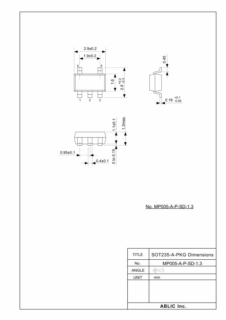
SOT-23-5 MP005-A-P-SD MP005-A-C-SD MP005-A-R-SD
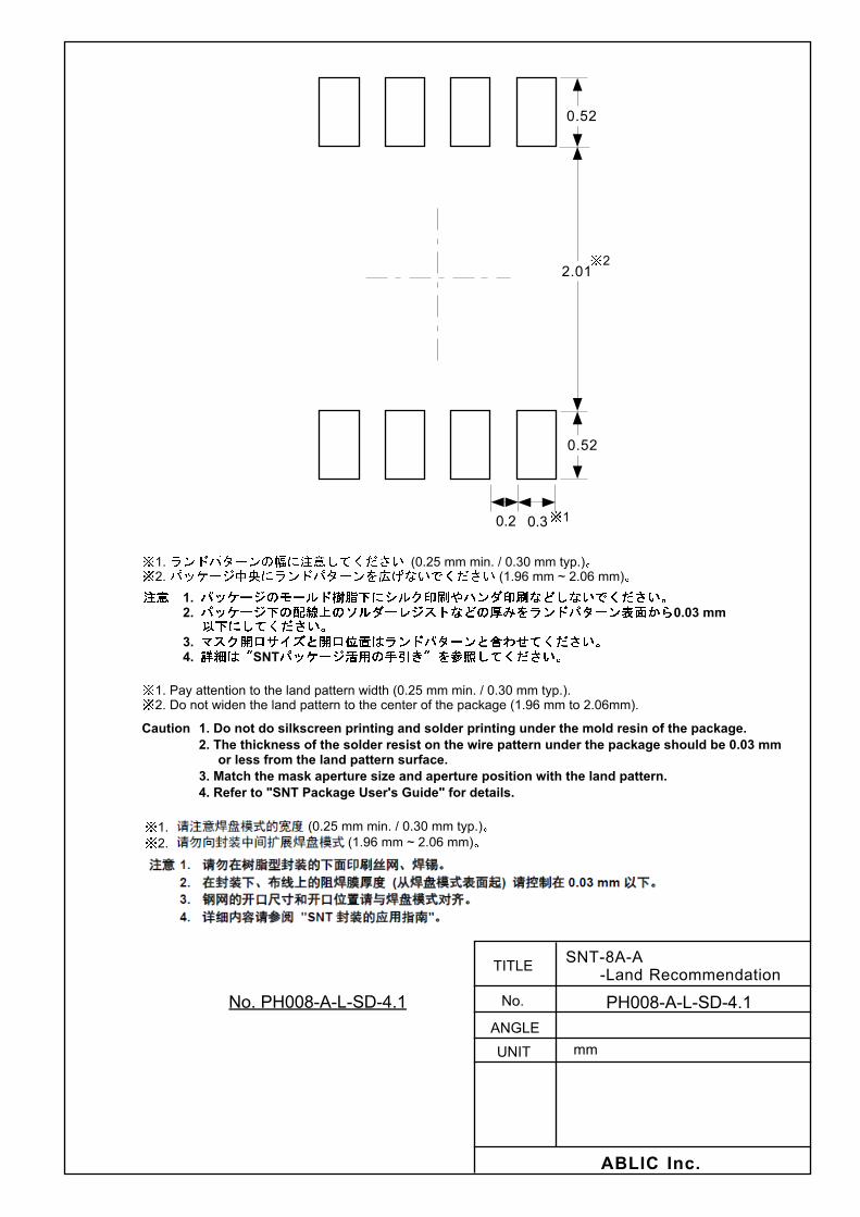
SNT-8A PH008-A-P-SD PH008-A-C-SD PH008-A-R-SD PH008-A-L-SD

STEP-DOWN, BUILT-IN FET, SYNCHRONOUS RECTIFICATION, PWM CONTROL SWITCHING REGULATORSS-8550 Series Rev.5.0_02
4
Pin Configurations 1. SOT-23-5
Table 1
1 32
45
Top view
Figure 3
Pin No. Symbol Description
1 VIN IC power supply pin
2 VSS GND pin
3
ON/OFF
Shutdown pin
“H” : Power on (normal operation)
“L” : Power off (standby)
4 FB Output voltage feedback pin
5 CONT External inductor connection pin
2. SNT-8A Table 2
765
8234
1
Top view
Figure 4
Pin No. Symbol Description
1 FB Output voltage feedback pin
2 NC*1 No connection
3 VSS*2 Small signal GND Pin
4
ON/OFF
Shutdown pin “H”:Power on (normal operation) “L”:Power off (standby)
5 VIN IC power supply pin
6 PVSS*2 Power GND pin
7 NC*1 No connection
8 CONT External inductor connection pin
*1. The NC pin is electrically open.
The NC pin can be connected to VIN, VSS or PVSS. *2. Connect VSS and PVSS to GND.

STEP-DOWN, BUILT-IN FET, SYNCHRONOUS RECTIFICATION, PWM CONTROL SWITCHING REGULATORSRev.5.0_02 S-8550 Series
5
Absolute Maximum Ratings
Table 3 Absolute Maximum Ratings
(Unless otherwise specified: Ta 25C, VSS 0 V)
Item Symbol Absolute Maximum Rating Unit
VIN pin voltage VIN VSS 0.3 to VSS + 6.0 V
FB pin voltage VFB VSS 0.3 to VIN + 0.3 V
CONT pin voltage VCONT VSS 0.3 to VIN + 0.3 V
ON/OFF pin voltage VON/OFF VSS 0.3 to VIN + 0.3 V
CONT pin current ICONT 1300 mA
Power dissipation
SOT-23-5 PD
600*1 mW
SNT-8A 450*1 mW
Operating temperature Topr 40 to +85 C
Storage temperature Tstg 40 to +125 C
*1. When mounted on printed circuit board
[Mounted board]
(1) Board size: 114.3 mm × 76.2 mm × t1.6 mm
(2) Board name: JEDEC STANDARD51-7
Caution 1. The absolute maximum ratings are rated values exceeding which the product could suffer
physical damage. These values must therefore not be exceeded under any conditions.
2. Since this IC has a built-in power MOS FET, make sure that dissipation of the power MOS FET
does not exceed the allowable power dissipation of the package. (Refer to Figure 5.)
Generally, dissipation of a switching regulator can be calculated by the following equation.
Dissipation = (100 (%) efficiency (%)) / efficiency (%) output voltage load current
The greater part of dissipation depends on the built-in power MOS FET, however, dissipation
of the inductor is also included.
In addition, since power dissipation of the package also changes according to a mounting
board or a mounting state, fully check them using an actually mounted mode.
0
400
0
Pow
er d
issi
patio
n (
PD)
[mW
]
Ambient temperature (Ta) [C]
200
500
300
100
600
700
50 100 150
SNT-8A
SOT-23-5
Figure 5 Power Dissipation of Package (Mounted on Board)

STEP-DOWN, BUILT-IN FET, SYNCHRONOUS RECTIFICATION, PWM CONTROL SWITCHING REGULATORSS-8550 Series Rev.5.0_02
6
Electrical Characteristics
Table 4 Electrical Characteristics
(Unless otherwise specified: VIN 3.6 V, VOUT 1.8 V (the conditions in Table 5), Ta +25C)
Item Symbol Condition Min. Typ. Max. Unit Test
Circuit
Operating input voltage VIN 2.0 5.5 V 2
Output voltage range*1 VOUT VIN = VOUT(S) + 0.4 V to 5.5 V 1.1 4.0 V 2
FB voltage VFB VIN = VOUT(S) + 0.4 V to 5.5 V 0.588 0.6 0.612 V 2
FB voltage temperature coefficient
VFB
Ta
Ta = 40C to +85C 100 ppm/C 2
FB pin input current IFB VIN = 2.0 V to 5.5 V, FB pin 0.1 +0.1 A 1
Current consumption during shutdown
ISSS VIN = 2.0 V to 5.5 V, VON/OFF 0 V
1.0 A 1
Current consumption 1 ISS1 fosc = 1.2 MHz, no external parts,VFB = VFB(S) 1.1 V
200 400 A 1
Power MOS FET on-resistance
RPFET ICONT = 100 mA 0.4 0.6 1
RNFET ICONT = 100 mA 0.3 0.5
Power MOS FET leakage current
ILSW VIN = 2.0 V to 5.5 V, VON/OFF 0 V, VCONT = 0 or 3.6 V
0.01 0.5 A 1
Limit current ILIM 800 1000 1200 mA 1
Oscillation frequency fosc 1.02 1.2 1.38 MHz 2
Soft-start time tSS Time required to reach 90% of VOUT(S)
0.7 1.0 1.3 ms 2
High level input voltage VSH VIN = 2.0 V to 5.5 V, ON/OFF pin 0.9 V 2
Low level input voltage VSL VIN = 2.0 V to 5.5 V, ON/OFF pin 0.3 V 2
High level input current ISH VIN = 2.0 V to 5.5 V, ON/OFF pin 0.1 0.1 A 1
Low level input current ISL VIN = 2.0 V to 5.5 V, ON/OFF pin 0.1 0.1 A 1
UVLO detection voltage VUVLO 1.4 1.6 1.78 V 2
*1. VOUT(S) is the output voltage set value, and VOUT is the typ. value of the actual output voltage.
VOUT(S) can be set depending on the ratio between the VFB value and output voltage set resistors (RFB1, RFB2).
For details, refer to “ External Parts Selection”.
External Parts When Measuring Electrical Characteristics
Table 5 External Parts
Element Name Symbol Constant Manufacturer Part Number
Inductor L 3.3 H Taiyo Yuden Co., Ltd. NR4018T3R3M
Input capacitor CIN 4.7 F TDK Corporation C3216X7R1E475K
Output capacitor COUT 10 F TDK Corporation C3216X7R1C106K
Output voltage set resistor 1 RFB1 36 k Rohm Co., Ltd. MCR03 Series 3602
Output voltage set resistor 2 RFB2 18 k Rohm Co., Ltd. MCR03 Series 1802
Phase compensation capacitor CFB 68 pF Murata Manufacturing Co., Ltd. GRM1882C1H680J

STEP-DOWN, BUILT-IN FET, SYNCHRONOUS RECTIFICATION, PWM CONTROL SWITCHING REGULATORSRev.5.0_02 S-8550 Series
7
Test Circuits
1.
S-8550 Series
ON/OFF
A
↓
CIN
CONT
FB
VSS
VIN
PVSS*1
*1. PVSS pin is unavailable for the S-8550 Series with SOT-23-5. Figure 6 2. L
S-8550 Series
ON/OFF
CIN
CONT
FB
VSS
VIN
V
V ↓IOUT
VOUT
CFBCOUT
RFB1
RFB2PVSS*1
*1. PVSS pin is unavailable for the S-8550 Series with SOT-23-5. Figure 7

STEP-DOWN, BUILT-IN FET, SYNCHRONOUS RECTIFICATION, PWM CONTROL SWITCHING REGULATORSS-8550 Series Rev.5.0_02
8
Operation
1. Synchronous rectification PWM control step-down switching regulator
1. 1 Synchronous rectification
The synchronous rectification method lowers voltage drop to greatly reduce power dissipation since an Nch
power MOS FET, having resistance much lower than conventional switching regulators, is used.
In conventional switching regulators, current flows in the diode connected between the GND and CONT pins
when the Pch power MOS FET is off. The forward drop voltage (Vf) of such diodes is large, between 0.3 V
to 0.7 V, so the power dissipation used to be very large. Synchronous rectification ultra-low resistance Nch
transistors repeat on and off, in synchronization with the operation of the Pch driver, in the reverse cycle of
the Pch driver. Moreover, the built-in P and N through prevention circuit helps much reduction of power
consumption during operation.
1. 2 PWM control
The S-8550 Series is a switching regulator using a pulse width modulation method (PWM) and features low
current consumption.
In conventional PFM control switching regulators, pulses are skipped when the output load current is low,
causing a fluctuation in the ripple frequency of the output voltage, resulting in an increase in the ripple
voltage.
In the S-8550 Series, the switching frequency does not change, although the pulse width changes from 0% to
100% corresponding to each load current. The ripple voltage generated from switching can thus be
removed easily using a filter because the switching frequency is constant.
2. Soft-start function
The soft-start circuit built in the S-8550 Series controls the rush current and the overshoot of the output voltage
when powering on, the ON/OFF pin is switched from the “L” level to the “H” level, or the UVLO operation is
released. A reference voltage adjustment method is adopted as the soft-start method.
3. Shutdown pin
This pin stops or starts step-up operations.
Switching the shutdown pin to the “L” level stops operation of all the internal circuits and reduces the current
consumption significantly. DO NOT use the shutdown pin in a floating state because it is not pulled up or
pulled down internally. DO NOT apply voltage of between 0.3 V and 0.9 V to the shutdown pin because
applying such a voltage increases the current consumption. If the shutdown pin is not used, connect it to the
VIN pin.
Table 6
Shutdown Pin CR Oscillation Circuit Output Voltage
“H” Operates Set value
“L” Stops Hi-Z
VIN
ON/OFF
VSS
Figure 8
STEP-DOWN, BUILT-IN FET, SYNCHRONOUS RECTIFICATION, PWM CONTROL SWITCHING REGULATORSRev.5.0_02 S-8550 Series
9
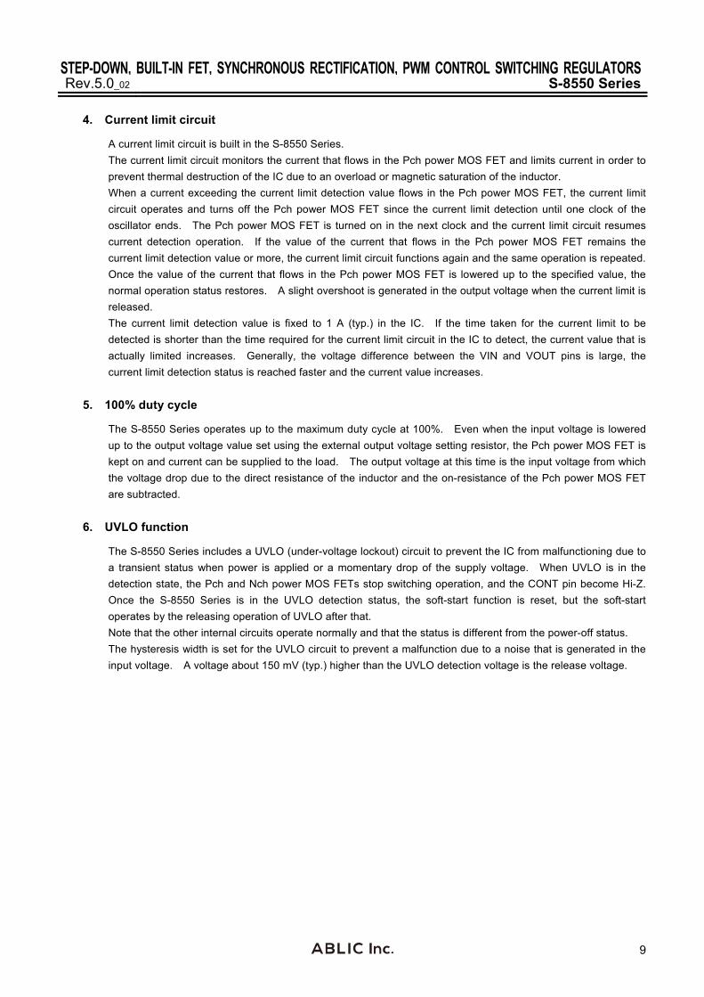
4. Current limit circuit
A current limit circuit is built in the S-8550 Series.
The current limit circuit monitors the current that flows in the Pch power MOS FET and limits current in order to
prevent thermal destruction of the IC due to an overload or magnetic saturation of the inductor.
When a current exceeding the current limit detection value flows in the Pch power MOS FET, the current limit
circuit operates and turns off the Pch power MOS FET since the current limit detection until one clock of the
oscillator ends. The Pch power MOS FET is turned on in the next clock and the current limit circuit resumes
current detection operation. If the value of the current that flows in the Pch power MOS FET remains the
current limit detection value or more, the current limit circuit functions again and the same operation is repeated.
Once the value of the current that flows in the Pch power MOS FET is lowered up to the specified value, the
normal operation status restores. A slight overshoot is generated in the output voltage when the current limit is
released.
The current limit detection value is fixed to 1 A (typ.) in the IC. If the time taken for the current limit to be
detected is shorter than the time required for the current limit circuit in the IC to detect, the current value that is
actually limited increases. Generally, the voltage difference between the VIN and VOUT pins is large, the
current limit detection status is reached faster and the current value increases.
5. 100% duty cycle
The S-8550 Series operates up to the maximum duty cycle at 100%. Even when the input voltage is lowered
up to the output voltage value set using the external output voltage setting resistor, the Pch power MOS FET is
kept on and current can be supplied to the load. The output voltage at this time is the input voltage from which
the voltage drop due to the direct resistance of the inductor and the on-resistance of the Pch power MOS FET
are subtracted.
6. UVLO function
The S-8550 Series includes a UVLO (under-voltage lockout) circuit to prevent the IC from malfunctioning due to
a transient status when power is applied or a momentary drop of the supply voltage. When UVLO is in the
detection state, the Pch and Nch power MOS FETs stop switching operation, and the CONT pin become Hi-Z.
Once the S-8550 Series is in the UVLO detection status, the soft-start function is reset, but the soft-start
operates by the releasing operation of UVLO after that.
Note that the other internal circuits operate normally and that the status is different from the power-off status.
The hysteresis width is set for the UVLO circuit to prevent a malfunction due to a noise that is generated in the
input voltage. A voltage about 150 mV (typ.) higher than the UVLO detection voltage is the release voltage.
STEP-DOWN, BUILT-IN FET, SYNCHRONOUS RECTIFICATION, PWM CONTROL SWITCHING REGULATORSS-8550 Series Rev.5.0_02
10
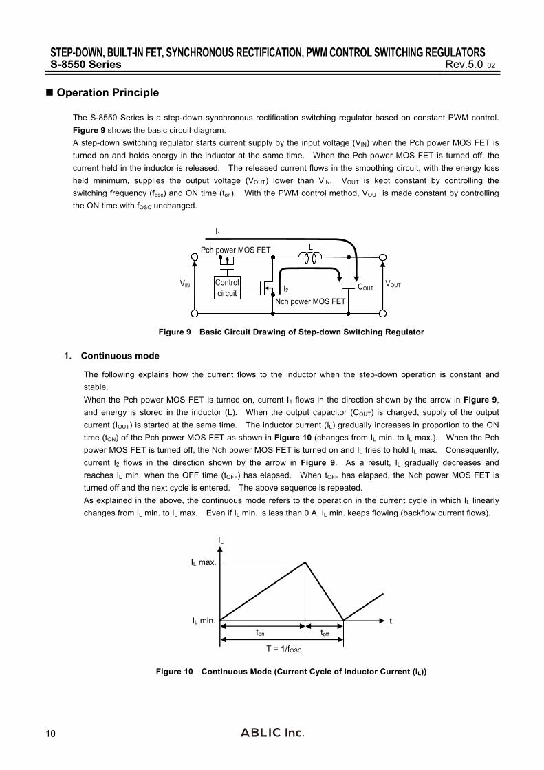
Operation Principle
The S-8550 Series is a step-down synchronous rectification switching regulator based on constant PWM control.
Figure 9 shows the basic circuit diagram.
A step-down switching regulator starts current supply by the input voltage (VIN) when the Pch power MOS FET is
turned on and holds energy in the inductor at the same time. When the Pch power MOS FET is turned off, the
current held in the inductor is released. The released current flows in the smoothing circuit, with the energy loss
held minimum, supplies the output voltage (VOUT) lower than VIN. VOUT is kept constant by controlling the
switching frequency (fosc) and ON time (ton). With the PWM control method, VOUT is made constant by controlling
the ON time with fOSC unchanged.
L
Control circuit
Pch power MOS FET
Nch power MOS FET
VIN VOUT COUT
I1
I2
Figure 9 Basic Circuit Drawing of Step-down Switching Regulator
1. Continuous mode
The following explains how the current flows to the inductor when the step-down operation is constant and
stable.
When the Pch power MOS FET is turned on, current I1 flows in the direction shown by the arrow in Figure 9,
and energy is stored in the inductor (L). When the output capacitor (COUT) is charged, supply of the output
current (IOUT) is started at the same time. The inductor current (IL) gradually increases in proportion to the ON
time (tON) of the Pch power MOS FET as shown in Figure 10 (changes from IL min. to IL max.). When the Pch
power MOS FET is turned off, the Nch power MOS FET is turned on and IL tries to hold IL max. Consequently,
current I2 flows in the direction shown by the arrow in Figure 9. As a result, IL gradually decreases and
reaches IL min. when the OFF time (tOFF) has elapsed. When tOFF has elapsed, the Nch power MOS FET is
turned off and the next cycle is entered. The above sequence is repeated.
As explained in the above, the continuous mode refers to the operation in the current cycle in which IL linearly
changes from IL min. to IL max. Even if IL min. is less than 0 A, IL min. keeps flowing (backflow current flows).
ton toff
T = 1/fOSC
IL
IL max.
IL min. t
Figure 10 Continuous Mode (Current Cycle of Inductor Current (IL))

STEP-DOWN, BUILT-IN FET, SYNCHRONOUS RECTIFICATION, PWM CONTROL SWITCHING REGULATORSRev.5.0_02 S-8550 Series
11
2. Backflow current
The S-8550 Series performs PWM synchronous rectification even if IL min. is less than 0 A, so a backflow
current is generated in VIN and the backflow current becomes maximum when no load is applied (Refer to
Figure 11). Use the following equation to calculate the maximum backflow current value, which should be
taken into consideration when designing.
Duty (IOUT 0) VOUT / VIN
Example : VIN 3.6 V, VOUT 1.8 V …… Duty 50%
IL V / L ton (VIN VOUT) Duty / (L fOSC)
Example : VIN 3.6 V, VOUT 1.8 V, fOSC 1.2 MHz, L 3.3 H …… IL 227 mA
IL max. IL / 2 113.5 mA, IL min. IL / 2 113.5 mA
The current value waveform of the inductor is a triangular wave, of which the maximum value is IL max. and the
minimum value is IL min. (negative value), and the negative value (the portion marked by diagonal lines in
Figure 11) backflows when no load is applied (Refer to Figure 11).
If about 113.5 mA of IOUT flows in the above conditions, the minimum value (IL min.) of the triangular wave is
made 0 mA and no backflow current flows.
When an input capacitor (CIN) is connected, the backflow current is absorbed by CIN, thus reducing the backflow
current to flow in the power supply. Be sure to connect an input capacitor to reduce backflow current to the
power supply (Refer to Figure 12).
The above presents the conditions required to prevent backflow current from flowing, which is only a guideline.
Perform sufficient confirmation using an actual application.
Inductor current with no load Inductor current when load is a current of 113.5 mA
Backflow current
113.5 mA
113.5 mA
IL min.
IL max.
IL
IL
0 mA
Backflow current = 0 mA
0 mA IOUT
113.5 mA IOUT
227 mA
IL min.
IL max.
IL
IL
Figure 11 Example of Conditions to Prevent Backflow Current from Flowing
VOUT
VIN CONT
Backflow current
Inductor current IL
CIN
VIN
Figure 12 Backflow Current

STEP-DOWN, BUILT-IN FET, SYNCHRONOUS RECTIFICATION, PWM CONTROL SWITCHING REGULATORSS-8550 Series Rev.5.0_02
12
External Parts Selection
1. Inductor
The inductance (L value) has a strong influence on the maximum output current (IOUT) and efficiency ().
The peak current (IPK) increases by decreasing L and the stability of the circuit improves and IOUT increases. If
L is decreased further, the current drive capability of the external transistor is insufficient and IOUT decreases.
If the L value is increased, the loss due to IPK of the power MOS FET decreases and the efficiency becomes
maximum at a certain L value. Further increasing L decreases the efficiency due to the increased loss of the
DC resistance of the inductor.
The recommended L value for the S-8550 Series is 3.3 H.
When selecting an inductor, note the allowable current of the inductor. If a current exceeding this allowable
current flows through the inductor, magnetic saturation occurs, substantially lowering the efficiency.
Therefore, select an inductor so that IPK does not exceed the allowable current. IPK is expressed by the
following equations in the discontinuous mode and continuous mode.
2 fOSC L VIN IPK = IOUT +
VOUT (VIN VOUT)
fOSC Oscillation frequency
Table 7 Typical Inductors
Manufacturer Part Number L ValueDC
Resistance Rated Current
Dimensions (L W H) [mm]
Taiyo Yuden Co., Ltd. NR4018T3R3M 3.3 H 0.07 max. 1.23 A max. 4.0 4.0 1.8
NR3012T3R3M 3.3 H 0.1 max. 0.91 A max. 3.0 3.0 1.2
Sumida Corporation CDRH3D16/HP-3R3 3.3 H 0.085 max. 1.40 A max. 4.0 4.0 1.8
CDRH2D11/HP-3R3 3.3 H 0.173 max. 0.9 A max. 3.2 3.2 1.2
TDK Corporation VLF4012AT-3R3M 3.3 H 0.12 max. 1.3 A max. 3.7 3.5 1.2
VLF3010AT-3R3M 3.3 H 0.17 max. 0.87 A max. 2.6 2.8 1.0
FDK Corporation MIP3226D3R3M 3.3 H 0.104 max. 1.2 A max. 3.2 2.6 1.0
MIPS2520D3R3M 3.3 H 0.156 max. 1.0 A max. 2.5 2.0 1.0

STEP-DOWN, BUILT-IN FET, SYNCHRONOUS RECTIFICATION, PWM CONTROL SWITCHING REGULATORSRev.5.0_02 S-8550 Series
13
2. Capacitors (CIN, COUT)
A ceramic capacitor can be used for the input (CIN) and output (COUT) sides. CIN lowers the power supply
impedance and averages the input current to improve efficiency. Select CIN according to the impedance of the
power supply to be used. The recommended capacitance is 4.7 F for the S-8550 Series when a general
lithium ion rechargeable battery is used.
Select as COUT a capacitor with large capacitance and small ESR for smoothing the ripple voltage. The
optimum capacitor selection depends on the L value, capacitance value, wiring, and application (output load).
Select COUT after sufficient evaluation under actual use conditions.
3. Output voltage setting resistors (RFB1, RFB2), capacitor for phase compensation (CFB)
With the S-8550 Series, VOUT can be set to any value by external divider resistors. Connect the divider
resistors across the VOUT and VSS pins. Because VFB 0.6 V typ., VOUT can be calculated by this equation.
VOUT = (RFB1 RFB2)
RFB2 0.6
Connect divider resistors RFB1 and RFB2 as close to the IC to minimize effects from of noise. If noise does have
an effect, adjust the values of RFB1 and RFB2 so that RFB1 RFB2 < 100 k.
CFB connected in parallel with RFB1 is a capacitor for phase compensation.
By setting the zero point (the phase feedback) by adding capacitor CFB to output voltage setting resistor RFB1 in
parallel, the feedback loop gains the phase margin. As a result, the stability can be obtained. In principle, to use
the portion how much the phase has feed back by the zero point effectively, define CFB referring to the following
equation.
CFB 1
2 RFB1 70 kHz
This equation is the reference.
The followings are explanation regarding the proper setting.
To use the portion how much the phase has feed back by the zero point effectively, set RFB1 and CFB so that the
zero point goes into the higher frequency than the pole frequency of L and COUT. The following equations are the
pole frequency of L and COUT and the zero point frequency by CFB and RFB1.
fpole 1
2 L COUT
fzero 1
2 RFB1 CFB
The transient response can be improved by setting the zero point frequency in the range of lower frequency.
However, since the gain becomes higher in the range of high frequency, the total phase of feedback loop delays
180 or more by setting the zero point frequency in the significantly lower range. As a result, the gain cannot be
0 dB or lower in the frequency range thus the operation might be unstable. Determine the proper value after the
sufficient evaluation under the actual condition.
The typical constants by our evaluation are in Table 8.
Table 8 Constant for External Parts
VOUT(s) [V] RFB1 [k] RFB2 [k] CFB [pF] L [H]*1 COUT [F]*1
1.1 36 43 56 3.3 10
1.8 36 18 68 3.3 10
3.3 36 8 120 3.3 10
4.0 51 9 100 3.3 10
*1. The recommended parts in Table 5

STEP-DOWN, BUILT-IN FET, SYNCHRONOUS RECTIFICATION, PWM CONTROL SWITCHING REGULATORSS-8550 Series Rev.5.0_02
14
Standard Circuits 1. SOT-23-5
L
ON/OFF
VIN
CIN
FB
VIN
CONT
VSS
CFB
RFB1
RFB2
VOUT
COUT
*1
*1
4.7 F
3.3 H
36 k
18 k 10 F
68 pF
1.0 F
Reference voltage
PWM comparator
PWM control circuit
UVLO circuitON/OFF circuit
IC internal power supply
Current limit circuit
Error amplifier
Ground point
Triangular wavegeneration
circuit
*1. Parasitic diode
Figure 13
2. SNT-8A
L
ON/OFF
VIN
CIN
FB
VIN
CONT
VSS
CFB
RFB1
RFB2
VOUT
COUT
*1
*1
4.7 F
3.3 H
36 k
18 k 10 F
68 pF
1.0 F
Reference voltage
PWM comparator
PWM control circuit
UVLO circuitON/OFF circuit
IC internal power supply
Current limit circuit
Error amplifier
Ground point
Triangular wavegeneration
circuit
PVSS
*1. Parasitic diode
Figure 14
Caution The above connection diagram and constant will not guarantee successful operation. Perform thorough
evaluation using an actual application to set the constants.

STEP-DOWN, BUILT-IN FET, SYNCHRONOUS RECTIFICATION, PWM CONTROL SWITCHING REGULATORSRev.5.0_02 S-8550 Series
15
Precaution
Mount external capacitors, diodes, and inductors as close as possible to the IC, and make a one-point grounding.
Characteristics ripple voltage and spike noise occur in IC containing switching regulators. Moreover rush current
flows at the time of a power supply injection. Because these largely depend on the inductor, the capacitor and
impedance of power supply used, fully check them using an actually mounted model.
The 1.0 F capacitance connected between the VIN and VSS pins is a bypass capacitor. It stabilizes the power
supply in the IC when application is used with a heavy load, and thus effectively works for stable switching
regulator operation. Allocate the bypass capacitor as close to the IC as possible, prioritized over other parts.
Although the IC contains a static electricity protection circuit, static electricity or voltage that exceeds the limit of
the protection circuit should not be applied.
The power dissipation of the IC greatly varies depending on the size and material of the board to be connected.
Perform sufficient evaluation using an actual application before designing.
ABLIC Inc. assumes no responsibility for the way in which this IC is used on products created using this IC or for
the specifications of that product, nor does ABLIC Inc. assume any responsibility for any infringement of patents or
copyrights by products that include this IC either in Japan or in other countries.
STEP-DOWN, BUILT-IN FET, SYNCHRONOUS RECTIFICATION, PWM CONTROL SWITCHING REGULATORSS-8550 Series Rev.5.0_02
16
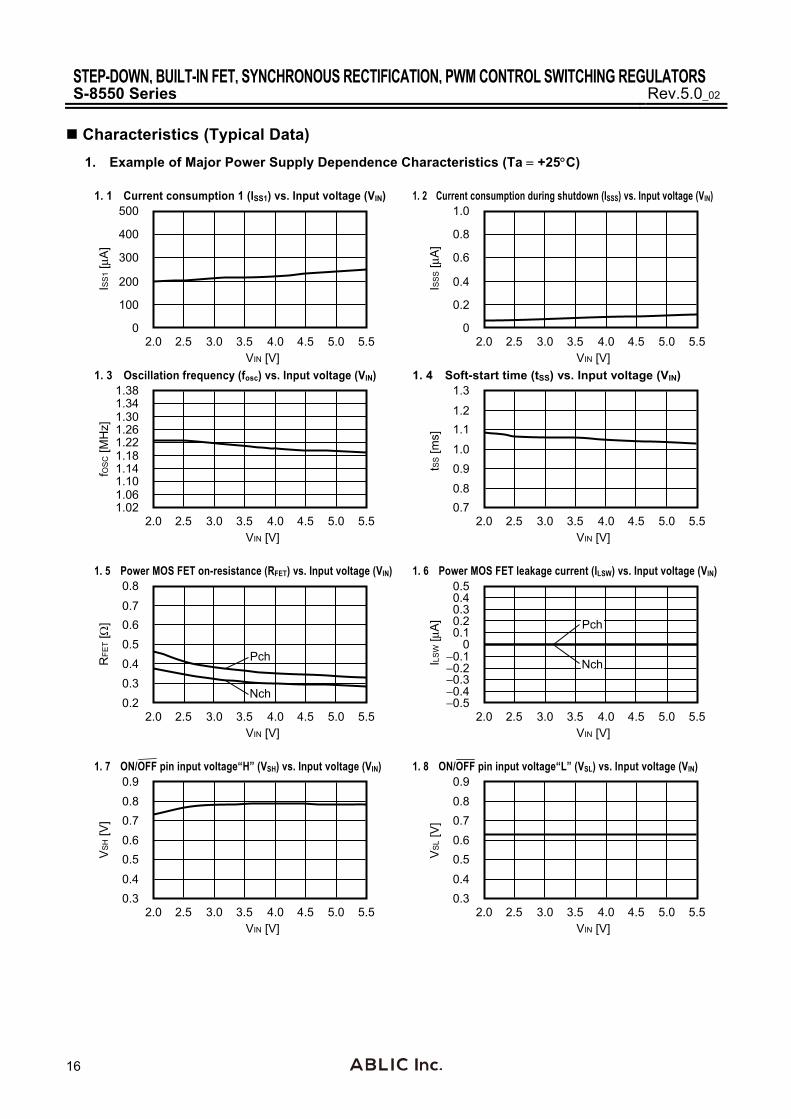
Characteristics (Typical Data)
1. Example of Major Power Supply Dependence Characteristics (Ta +25C)
1. 1 Current consumption 1 (ISS1) vs. Input voltage (VIN) 1. 2 Current consumption during shutdown (ISSS) vs. Input voltage (VIN)
2.0 4.0 5.0 5.5
ISS
1 [μA
]
500
400
300
200
100
0
VIN [V]2.5 3.0 3.5 4.5 2.0 4.0 5.0 5.5
ISS
S [μ
A]
1.0
0.8
0.6
0.4
0.2
0
VIN [V]2.5 3.0 3.5 4.5
1. 3 Oscillation frequency (fosc) vs. Input voltage (VIN) 1. 4 Soft-start time (tSS) vs. Input voltage (VIN)
2.0 4.0 5.0 5.5
fOS
C [M
Hz]
1.38
1.30
1.18
1.10
1.02
VIN [V]2.5 3.0 3.5 4.5
1.06
1.14
1.221.26
1.34
2.0 4.0 5.0 5.5
tSS [m
s]
1.3
1.1
1.00.9
0.7
VIN [V]2.5 3.0 3.5 4.5
0.8
1.2
1. 5 Power MOS FET on-resistance (RFET) vs. Input voltage (VIN) 1. 6 Power MOS FET leakage current (ILSW) vs. Input voltage (VIN)
2.0 4.0 5.0 5.5
RFE
T [
]
0.8
0.60.50.4
0.2
VIN [V]2.5 3.0 3.5 4.5
0.3
0.7
Nch
Pch
2.0 4.0 5.0 5.5
ILSW
[μA
]
0.5
0.10
−0.1
−0.5
VIN [V]2.5 3.0 3.5 4.5
−0.4
0.4
Nch
Pch0.20.3
−0.2−0.3
1. 7 ON/OFF pin input voltage“H” (VSH) vs. Input voltage (VIN) 1. 8 ON/OFF pin input voltage“L” (VSL) vs. Input voltage (VIN)
2.0 4.0 5.0 5.5
VS
H [V
]
0.9
0.6
0.3
VIN [V]2.5 3.0 3.5 4.5
0.70.8
0.50.4
2.0 4.0 5.0 5.5
VS
L [V
]
0.9
0.6
0.3
VIN [V]2.5 3.0 3.5 4.5
0.70.8
0.50.4
STEP-DOWN, BUILT-IN FET, SYNCHRONOUS RECTIFICATION, PWM CONTROL SWITCHING REGULATORSRev.5.0_02 S-8550 Series
17
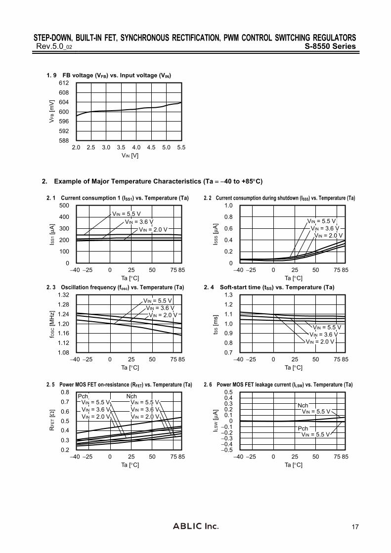
1. 9 FB voltage (VFB) vs. Input voltage (VIN)
2.0 4.0 5.0 5.5
VFB
[mV
]
612
600
588
VIN [V]2.5 3.0 3.5 4.5
604608
596592
2. Example of Major Temperature Characteristics (Ta 40 to +85C)
2. 1 Current consumption 1 (ISS1) vs. Temperature (Ta) 2. 2 Current consumption during shutdown (ISSS) vs. Temperature (Ta)
−40 75 85
ISS
1 [μA
]
500
0−25 0 25 50
300
400
200
100
Ta [C]
VIN = 5.5 VVIN = 3.6 V
VIN = 2.0 V
−40 75 85
ISS
S [μ
A]
1.0
0−25 0 25 50
0.6
0.8
0.4
0.2
Ta [C]
VIN = 5.5 VVIN = 3.6 V
VIN = 2.0 V
2. 3 Oscillation frequency (fosc) vs. Temperature (Ta) 2. 4 Soft-start time (tSS) vs. Temperature (Ta)
−40 75 85
fOS
C [M
Hz]
1.32
1.08−25 0 25 50
1.28
1.201.16
Ta [C]
VIN = 5.5 VVIN = 3.6 VVIN = 2.0 V
1.12
1.24
−40 75 85
tSS [m
s]
1.3
0.7−25 0 25 50
1.11.00.9
Ta [C]
VIN = 5.5 VVIN = 3.6 V
VIN = 2.0 V0.8
1.2
2. 5 Power MOS FET on-resistance (RFET) vs. Temperature (Ta) 2. 6 Power MOS FET leakage current (ILSW) vs. Temperature (Ta)
−40 75 85
RFE
T [
]
0.8
0.2−25 0 25 50
Ta [C]
VIN = 5.5 VVIN = 3.6 VVIN = 2.0 V
VIN = 5.5 VVIN = 3.6 VVIN = 2.0 V
Pch Nch
0.60.50.4
0.3
0.7
−40 75 85
ILSW
[μA
]
0.5
−0.5−25 0 25 50
Ta [C]
VIN = 5.5 V
VIN = 5.5 V
Pch
Nch0.1
0−0.1
−0.4
0.4
0.20.3
−0.2−0.3

STEP-DOWN, BUILT-IN FET, SYNCHRONOUS RECTIFICATION, PWM CONTROL SWITCHING REGULATORSS-8550 Series Rev.5.0_02
18
2. 7 ON/OFF pin input voltage“H” (VSH) vs. Temperature (Ta) 2. 8 ON/OFF pin input voltage“L” (VSL) vs. Temperature (Ta)
−40 75 85
VS
H [V
]
0.9
0.3−25 0 25 50
Ta [C]
0.60.70.8
0.50.4
VIN = 3.6 VVIN = 5.5 V
VIN = 2.0 V
−40 75 85
VS
L [V
]
0.9
0.3−25 0 25 50
Ta [C]
0.60.70.8
0.50.4
VIN = 5.5 VVIN = 3.6 V
VIN = 2.0 V
2. 9 UVLO detection voltage (VUVLO) vs. Temperature (Ta) 2. 10 FB voltage (VFB) vs. Temperature (Ta)
−40 75 85
VU
VLO
[V]
1.80
1.40−25 0 25 50
Ta [C]
1.60
1.701.75
1.55
1.451.50
1.65
−40 75 85
VFB
[mV
]
612
588−25 0 25 50
Ta [C]
600604608
596592
VIN = 5.5 VVIN = 3.6 V
VIN = 2.0 V
3. Examples of Transient Response Characteristics (Unless otherwise specified, the used parts are ones shown in External Parts When Measuring Electrical Characteristics.)
3. 1 Powering ON (VOUT 1.8 V, VIN 0 V → 3.6 V, Ta +25C)
(1) IOUT = 1 mA (2) IOUT = 600 mA
−0.2 0.6 1.0 1.6
VIN
, VO
UT
[V]
43
10
−1
t [ms]
IL [A
]
0.6
0.20.4
−0.20
0 0.2 0.4 0.8
VOUT
VIN
IL
2
1.2 1.4 −0.2 0.6 1.0 1.6
VIN
, VO
UT
[V]
43
10
−1
t [ms]
IL [A
]
1.5
0.51.0
−0.50
0 0.2 0.4 0.8
2
1.2 1.4
VOUT
VIN
IL
3. 2 Shutdown pin response (VOUT 1.8 V, VIN 3.6 V, VON/OFF 0 V → 3.6 V, Ta +25C)
(1) IOUT = 1 mA (2) IOUT = 600 mA
−0.2 0.6 1.0 1.6
VO
N/O
FF, V
OU
T [V
]
43
10
−1
t [ms]
IL [A
]
0.6
0.20.4
−0.20
0 0.2 0.4 0.8
2
1.2 1.4
VOUT
VON/OFF
IL
−0.2 0.6 1.0 1.6
VO
N/O
FF, V
OU
T [V
]
43
10
−1
t [ms]
IL [A
]
1.5
0.51.0
−0.50
0 0.2 0.4 0.8
2
1.2 1.4
VOUT
VON/OFF
IL

STEP-DOWN, BUILT-IN FET, SYNCHRONOUS RECTIFICATION, PWM CONTROL SWITCHING REGULATORSRev.5.0_02 S-8550 Series
19
3. 3 Power supply fluctuations (VOUT 1.8 V, Ta +25C)
(1) IOUT = 1 mA, VIN 2.6 V → 3.6 V → 2.6 V (2) IOUT = 600 mA, VIN 2.6 V → 3.6 V → 2.6 V
−0.1 0.3 0.5 0.7
VO
UT
[V]
2.22.01.81.61.4
t [ms]
VIN
[V]
3.52.51.50.5
4.5
0 0.1 0.2 0.4 0.6
VOUT
VIN
−0.1 0.3 0.5 0.7
VO
UT
[V]
2.22.01.81.61.4
t [ms]
VIN
[V]
3.52.51.50.5
4.5
0 0.1 0.2 0.4 0.6
VOUT
VIN
3. 4 Load fluctuations (VOUT 1.8 V, VIN 3.6 V, Ta +25C)
(1) IOUT = 0.1 mA → 100 mA → 0.1 mA (2) IOUT = 0.1 mA → 300 mA → 0.1 mA
−0.1 0.3 0.5 0.7
VO
UT
[V]
1.901.851.801.751.70
t [ms]
IOU
T [m
A] 200
1000−100
400
0 0.1 0.2 0.4 0.6
VOUT
IOUT
300
−0.1 0.3 0.5 0.7
VO
UT
[V]
1.901.851.801.751.70
t [ms]
IOU
T [m
A] 200
1000−100
400
0 0.1 0.2 0.4 0.6
300
VOUT
IOUT
STEP-DOWN, BUILT-IN FET, SYNCHRONOUS RECTIFICATION, PWM CONTROL SWITCHING REGULATORSS-8550 Series Rev.5.0_02
20
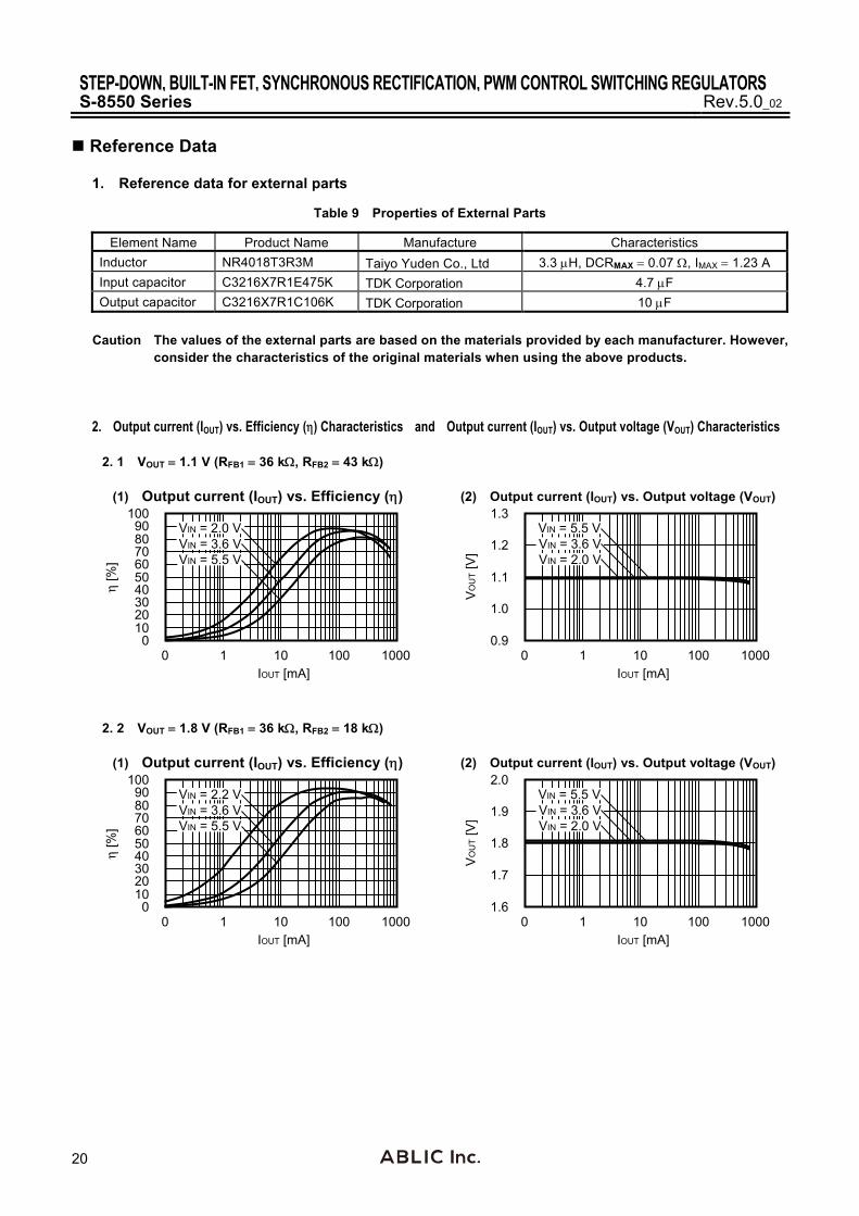
Reference Data
1. Reference data for external parts
Table 9 Properties of External Parts
Element Name Product Name Manufacture Characteristics
Inductor NR4018T3R3M Taiyo Yuden Co., Ltd 3.3 H, DCRMAX 0.07 , IMAX 1.23 A
Input capacitor C3216X7R1E475K TDK Corporation 4.7 F
Output capacitor C3216X7R1C106K TDK Corporation 10 F
Caution The values of the external parts are based on the materials provided by each manufacturer. However,
consider the characteristics of the original materials when using the above products.
2. Output current (IOUT) vs. Efficiency () Characteristics and Output current (IOUT) vs. Output voltage (VOUT) Characteristics
2. 1 VOUT 1.1 V (RFB1 36 k, RFB2 43 k)
(1) Output current (IOUT) vs. Efficiency () (2) Output current (IOUT) vs. Output voltage (VOUT)
0 1000
η [%
]
100
01 10 100
IOUT [mA]
50
7080
30
1020
40
60
90 VIN = 2.0 VVIN = 3.6 VVIN = 5.5 V
0 1000
VO
UT
[V]
1.3
0.91 10 100
IOUT [mA]
1.1
1.2
1.0
VIN = 5.5 VVIN = 3.6 VVIN = 2.0 V
2. 2 VOUT 1.8 V (RFB1 36 k, RFB2 18 k)
(1) Output current (IOUT) vs. Efficiency () (2) Output current (IOUT) vs. Output voltage (VOUT)
0 1000
η [%
]
100
01 10 100
IOUT [mA]
50
7080
30
1020
40
60
90 VIN = 2.2 VVIN = 3.6 VVIN = 5.5 V
0 1000
VO
UT
[V]
2.0
1.61 10 100
IOUT [mA]
1.8
1.9
1.7
VIN = 5.5 VVIN = 3.6 VVIN = 2.0 V

STEP-DOWN, BUILT-IN FET, SYNCHRONOUS RECTIFICATION, PWM CONTROL SWITCHING REGULATORSRev.5.0_02 S-8550 Series
21
2. 3 VOUT 3.3 V (RFB1 36 k, RFB2 8 k)
(1) Output current (IOUT) vs. Efficiency () (2) Output current (IOUT) vs. Output voltage (VOUT)
0 1000
η [%
]
100
01 10 100
IOUT [mA]
50
7080
30
1020
40
60
90 VIN = 3.7 VVIN = 5.5 V
0 1000
VO
UT
[V]
3.5
3.11 10 100
IOUT [mA]
3.3
3.4
3.2
VIN = 5.5 VVIN = 3.7 V
2. 4 VOUT 4.0 V (RFB1 51 k, RFB2 9 k)
(1) Output current (IOUT) vs. Efficiency () (2) Output current (IOUT) vs. Output voltage (VOUT)
0 1000
η [%
]
100
01 10 100
IOUT [mA]
50
7080
30
1020
40
60
90 VIN = 4.4 VVIN = 5.5 V
0 1000
VO
UT
[V]
4.2
3.81 10 100
IOUT [mA]
4.0
4.1
3.9
VIN = 5.5 VVIN = 4.4 V
3. Output current (IOUT) vs. Ripple voltage (Vr) Characteristics 3. 1 VOUT 1.1 V (RFB1 36 k, RFB2 43 k)
(1) VIN = 3.6 V (2) VIN = 5.5 V
0 1000
Vr [
mV
]
50
01 10 100
IOUT [mA]
30
40
10
20
0 1000
Vr [
mV
]
50
01 10 100
IOUT [mA]
30
40
10
20

STEP-DOWN, BUILT-IN FET, SYNCHRONOUS RECTIFICATION, PWM CONTROL SWITCHING REGULATORSS-8550 Series Rev.5.0_02
22
3. 2 VOUT 1.8 V (RFB1 36 k, RFB2 18 k)
(1) VIN = 3.6 V (2) VIN = 5.5 V
0 1000
Vr [
mV
]
50
01 10 100
IOUT [mA]
30
40
10
20
0 1000
Vr [
mV
]
50
01 10 100
IOUT [mA]
30
40
10
20
3. 3 VOUT 3.3 V (RFB1 36 k, RFB2 8 k)
(1) VIN = 3.6 V (2) VIN = 5.5 V
0 1000
Vr [
mV
]
50
01 10 100
IOUT [mA]
30
40
10
20
0 1000
Vr [
mV
]50
01 10 100
IOUT [mA]
30
40
10
20
3. 4 VOUT 4.0 V (RFB1 51 k, RFB2 9 k)
(1) VIN = 5.5 V
0 1000
Vr [
mV
]
50
01 10 100
IOUT [mA]
30
40
10
20

STEP-DOWN, BUILT-IN FET, SYNCHRONOUS RECTIFICATION, PWM CONTROL SWITCHING REGULATORSRev.5.0_02 S-8550 Series
23
Marking Specifications 1. SOT-23-5
1 2 3
45
Top view
(1) (2) (3) (4)
(1) to (3): Product code (Refer to Product name vs. Product code.) (4): Lot number
Product name vs. Product code
Product Name Product Code
(1) (2) (3) S-8550AA-M5T1x R 5 A
Remark 1. x: G or U 2. Please select products of environmental code = U for Sn 100%, halogen-free products.
2. SNT-8A
Top view
1 432
8 567
(1) (2) (3) (4)
(5) (6) (7) (8)
(9) (10) (11)
(1): Blank (2) to (4): Product code (Refer to Product name vs. Product code) (5), (6): Blank (7) to (11): Lot number
Product name vs. Product code
Product name Product code
(2) (3) (4)S-8550AA-I8T1U R 5 A
���
�����
���
����
������ ��
�� ����
�� ����
�� �����
�������
���������������� � �
��
�������������������
���������������
��������������� !"��!"
��

���
�����
���
����
������ ��
#���������
��������
#��������� ������� �������
��������
�������
���
� �
�����������$�������
�������$�������
��������$%&& � & � �%'
( )�)�& *+��!
�������,���'�+*- ".��������/
��

���
�����
���
����
������ ��
�����%0�
������
#������
,��1/ ,��1/
2�3� �4���
�����������5�������
�������5�������
��������5 6
�!6%&7 )�)&%8�!7��!�+- �* !+&%6�'%&+
��

���
�����
���
����
������ ��
�� ������
��������
���������
����
��
���������������� ���
�!�������������
�����!�������������
���
"���������� � � �
�#��

���
�����
���
����
������ ��
��
�!�����$�������
�������$%&& ��& � �%'�
�����!�����$�������
(��)�)�&�*+���
���������������
�������
,���"���
���
,����������������
��#������
���������
� ���
� �#�

���
�����
���
����
������ ��
�����%-�
������
,������
.#�/0 .#�/0
��1%&2�)�)&%3��2����+4��*��+&%1�'%&+
5�6�
�!�����7�������
��
�������7��1
�����!�����7�������
�8���
���
�����
���
����
������ ��
��
��������������%�)�7�*�����)%+���
�!�������������
������
����
����
����
�����!�������������
��� ��� ������� ������������������ ������������������� ���������� ����������������� ���������
������ ����������� ��������������� ���� ���������� ���������� ����������������� ��!!"���
�������������� ���������� ����������
"�#� �� ������������ ������$���������� �������� ������ �� ���������� ���
%�&����� ��'()��*������+���,��-����'������� ����
��� .�������������A���������+?'�0��� �.�� #����B����#���0
�
� !!"���
"
% ()�
����%?�%++��+����+��+4��1%�)�'%++�&��3�)+4�.�������������A���������+?'�0���������+�3�)���+4��1%�)�'%++�&��+��+4��*��+�&��=�+4��'%*:%2��.�� #����+�����#��0�
�
�
��
��� .�� #����B����#���0
.�������������A���������+?'�0

Disclaimers (Handling Precautions)
1. All the information described herein (product data, specifications, figures, tables, programs, algorithms and application circuit examples, etc.) is current as of publishing date of this document and is subject to change without notice.
2. The circuit examples and the usages described herein are for reference only, and do not guarantee the success of any specific mass-production design. ABLIC Inc. is not responsible for damages caused by the reasons other than the products described herein (hereinafter "the products") or infringement of third-party intellectual property right and any other right due to the use of the information described herein.
3. ABLIC Inc. is not responsible for damages caused by the incorrect information described herein.
4. Be careful to use the products within their specified ranges. Pay special attention to the absolute maximum ratings, operation voltage range and electrical characteristics, etc. ABLIC Inc. is not responsible for damages caused by failures and / or accidents, etc. that occur due to the use of the products outside their specified ranges.
5. When using the products, confirm their applications, and the laws and regulations of the region or country where they are used and verify suitability, safety and other factors for the intended use.
6. When exporting the products, comply with the Foreign Exchange and Foreign Trade Act and all other export-related laws, and follow the required procedures.
7. The products must not be used or provided (exported) for the purposes of the development of weapons of mass destruction or military use. ABLIC Inc. is not responsible for any provision (export) to those whose purpose is to develop, manufacture, use or store nuclear, biological or chemical weapons, missiles, or other military use.
8. The products are not designed to be used as part of any device or equipment that may affect the human body, human life, or assets (such as medical equipment, disaster prevention systems, security systems, combustion control systems, infrastructure control systems, vehicle equipment, traffic systems, in-vehicle equipment, aviation equipment, aerospace equipment, and nuclear-related equipment), excluding when specified for in-vehicle use or other uses. Do not apply the products to the above listed devices and equipments without prior written permission by ABLIC Inc. Especially, the products cannot be used for life support devices, devices implanted in the human body and devices that directly affect human life, etc. Prior consultation with our sales office is required when considering the above uses. ABLIC Inc. is not responsible for damages caused by unauthorized or unspecified use of our products.
9. Semiconductor products may fail or malfunction with some probability. The user of the products should therefore take responsibility to give thorough consideration to safety design including redundancy, fire spread prevention measures, and malfunction prevention to prevent accidents causing injury or death, fires and social damage, etc. that may ensue from the products' failure or malfunction. The entire system must be sufficiently evaluated and applied on customer's own responsibility.
10. The products are not designed to be radiation-proof. The necessary radiation measures should be taken in the product design by the customer depending on the intended use.
11. The products do not affect human health under normal use. However, they contain chemical substances and heavy metals and should therefore not be put in the mouth. The fracture surfaces of wafers and chips may be sharp. Be careful when handling these with the bare hands to prevent injuries, etc.
12. When disposing of the products, comply with the laws and ordinances of the country or region where they are used.
13. The information described herein contains copyright information and know-how of ABLIC Inc. The information described herein does not convey any license under any intellectual property rights or any other rights belonging to ABLIC Inc. or a third party. Reproduction or copying of the information from this document or any part of this document described herein for the purpose of disclosing it to a third-party without the express permission of ABLIC Inc. is strictly prohibited.
14. For more details on the information described herein, contact our sales office.
2.2-2018.06
www.ablic.com