S-72.3340 Optical Networks Course Lecture 12: The … links •Satellite links Radio relay stations...
54
S-72.3340 Optical Networks Course Lecture 12: The Course Recap Edward Mutafungwa Communications Laboratory, Helsinki University of Technology, P. O. Box 2300, FIN-02015 TKK, Finland Tel: +358 9 451 2318, E-mail: [email protected]
Transcript of S-72.3340 Optical Networks Course Lecture 12: The … links •Satellite links Radio relay stations...
S-72.3340 Optical Networks Course
Lecture 12: The Course Recap
Edward MutafungwaCommunications Laboratory, Helsinki University of Technology,
P. O. Box 2300,FIN-02015 TKK, Finland
Tel: +358 9 451 2318, E-mail: [email protected]

Apr 26, 2007 EMu/S-72.3340/TheRecap Slide 2 of 54
1. Introduction
Electrical communications
Light or optical communications
..011010..DataSource
Electrical signal source
Electrical signal
..011010..DataSource
Electrical signal source
Light source
Electrical signal
Optical signal

Apr 26, 2007 EMu/S-72.3340/TheRecap Slide 3 of 54
1. IntroductionElectrical repeaterMetallic cable
• Copper Links
• Terrestrial radio links
•Satellite links Radio relay stations
Orbiting satellite
•Fiber links
Electrical repeater
Electrical to Optical
converter
O → E E → O
Optical to electrical converterFiber

Apr 26, 2007 EMu/S-72.3340/TheRecap Slide 4 of 54
1. Introduction
Advantages of the fiber transmission media Low transmission loss (typically 0.2-0.5 dB/km) Large information carrying capacity (multi Gbit/s) Immunity to electromagnetic interference More secure to eavesdropping or wiretapping Smaller size and weight
Apr 26, 2007 EMu/S-72.3340/TheRecap Slide 5 of 54
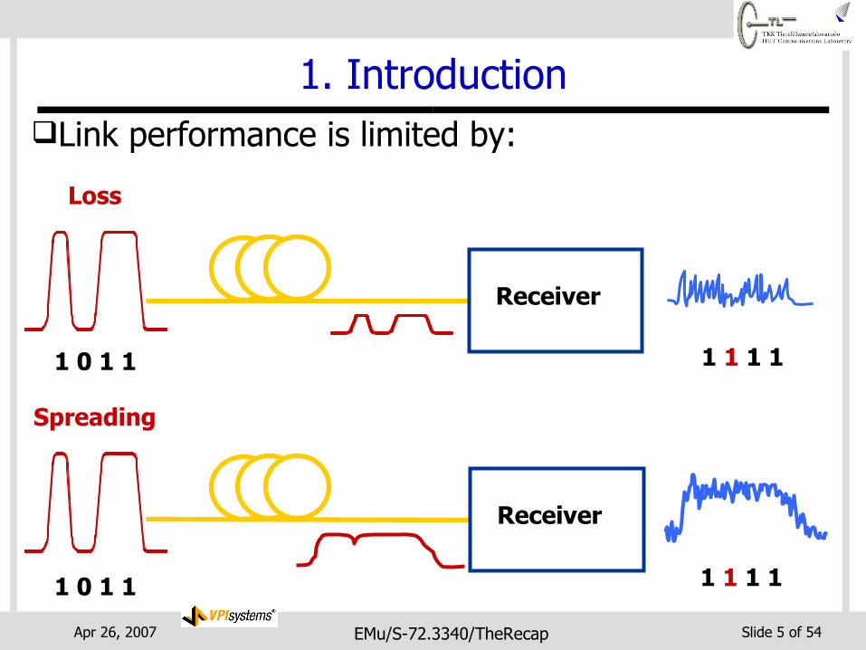
Link performance is limited by:
Loss
Receiver
Spreading
1 0 1 1 1 1 1 1
Receiver
1 0 1 1 1 1 1 1
1. Introduction

Apr 26, 2007 EMu/S-72.3340/TheRecap Slide 6 of 54
1. Introduction
Graphical representation of fiber limitations
Distance
Bit
Rat
e
Dispersion & Loss LimitedDispersion Limit
Loss Limit
Costly!
Feasible Regime

Apr 26, 2007 EMu/S-72.3340/TheRecap Slide 7 of 54
2. Wavelength-Division Multiplexing
Optical amplifier
WDM fiber link with optical amplification
Space-division multiplexing fiber link with electrical regeneration
O → E E → O
O → E E → O
O → E E → O
Electrical repeater
Electrical to Optical
converter
Optical to electrical converter
Fiber
O → E E → O
O → E E → O
O → E E → O
O → E E → O
O → E E → O
WDM fiber link with electrical regeneration

Apr 26, 2007 EMu/S-72.3340/TheRecap Slide 8 of 54
Third window“1550-nm”
2. Wavelength-Division MultiplexingAmplified optical communications systems
Optical amplification enables WDM in 1550 nm window Less attenuation than 850 nm and 1300 nm windows
First window“850-nm”
Second window“1300-nm”
6000.1
λ (nm)
0.2
0.5
1.0
2.0
5.0
10
Atte
nuat
ion
(dB/
km)
800 1000 1200 1400 1600 1800
Standard fiber
Low water-peakFiber
Less loss and zero dispersion
Optical signal sources available Optical amplification,
even lower loss

Apr 26, 2007 EMu/S-72.3340/TheRecap Slide 9 of 54
2. Wavelength-Division Multiplexing Coarse WDM (CWDM)
ITU-T G.694.2/695 grid with 2500 GHz or 20 nm channel spacing 18 channels spanning O-, E-, S-, C- and L-bands (1260-1625 nm)
Source: F. Audet, “Understanding CWDM,”EXFO application note.

Apr 26, 2007 EMu/S-72.3340/TheRecap Slide 10 of 54
2. Wavelength-Division Multiplexing DWDM enables many channels with amplification,
...but requires stable transmitters and good filtering (sharp skirts and precise center frequency)
CWDM simplifies filter and transmitter design (cheaper) ...but no amplification and few channels
Source: F. Audet, “Understanding CWDM,”EXFO application note.

Apr 26, 2007 EMu/S-72.3340/TheRecap Slide 11 of 54
2. Wavelength-Division Multiplexing A typical amplified WDM link includes:
Optical transmitters and receivers (1 each per wavelength) Wavelength multiplexer and demultiplexers Optical amplifiers
• Boost amplifier: to increase the output power • Line amplifier: to compensate for fiber losses• Preamplifier: to improve receiver sensitivity

Apr 26, 2007 EMu/S-72.3340/TheRecap Slide 12 of 54
2. Modulation/Demodulation
Two popular optical modulation schemes On-off keying (OOK) modulation Subcarrier modulation (SCM)

Apr 26, 2007 EMu/S-72.3340/TheRecap Slide 13 of 54
2.1 On-Off Keying (OOK) Modulation
It is possible to directly or externally modulate (i.e. turn off and on) a light source (laser or LED) Direct modulation ⇒ simple, chirp External modulation ⇒ more complex, less chirp

Apr 26, 2007 EMu/S-72.3340/TheRecap Slide 14 of 54
NRZ
1
Time
0 1
T
Binary Data 1
Time
0 1
TPo
wer
Pow
er
TimeTime
TTFWHM
RZ Duty Cycle = TFWHM/T where TFWHM is full width at half maximum of power
2.1 On-Off Keying (OOK) ModulationNon-Return-to-Zero (NRZ) format
Return-to-Zero (RZ) format

Apr 26, 2007 EMu/S-72.3340/TheRecap Slide 15 of 54
Subcarrier modulated (SCM) systems Multiplex multiple data streams onto one optical signal Each data stream assigned a unique subcarrier frequency
⇒ subcarrier multiplexing
×~
f1
Data stream 1
×~
f2
Data stream 2
×~
f3
Data stream 3
Laserfc
2.2 Subcarrier Modulation
5 signal subcarrier multiplexing

Apr 26, 2007 EMu/S-72.3340/TheRecap Slide 16 of 54
Data signal recovery is a two step process(1) Recovering the clock (2) Determining whether a “0” or “1” bit was sent in a bit
interval direct detection⇨
2.3 Demodulation
Apr 26, 2007 EMu/S-72.3340/TheRecap Slide 17 of 54
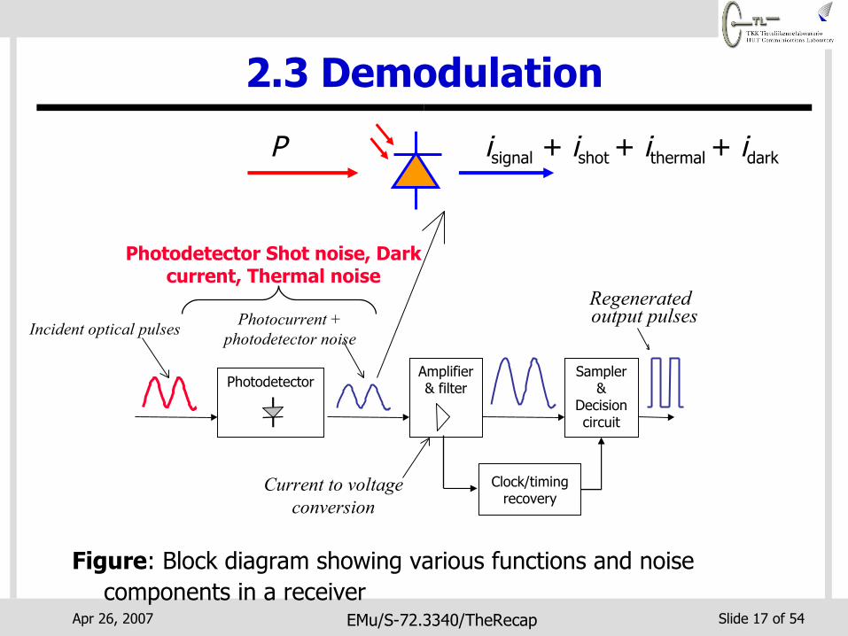
Figure: Block diagram showing various functions and noise components in a receiver
Regeneratedoutput pulsesPhotocurrent +
photodetector noise
Photodetector Shot noise, Dark current, Thermal noise
Incident optical pulses
PhotodetectorAmplifier & filter
Sampler &
Decision circuit
Clock/timing recovery
2.3 Demodulation
Current to voltage conversion
P isignal + ishot + ithermal + idark
Apr 26, 2007 EMu/S-72.3340/TheRecap Slide 18 of 54
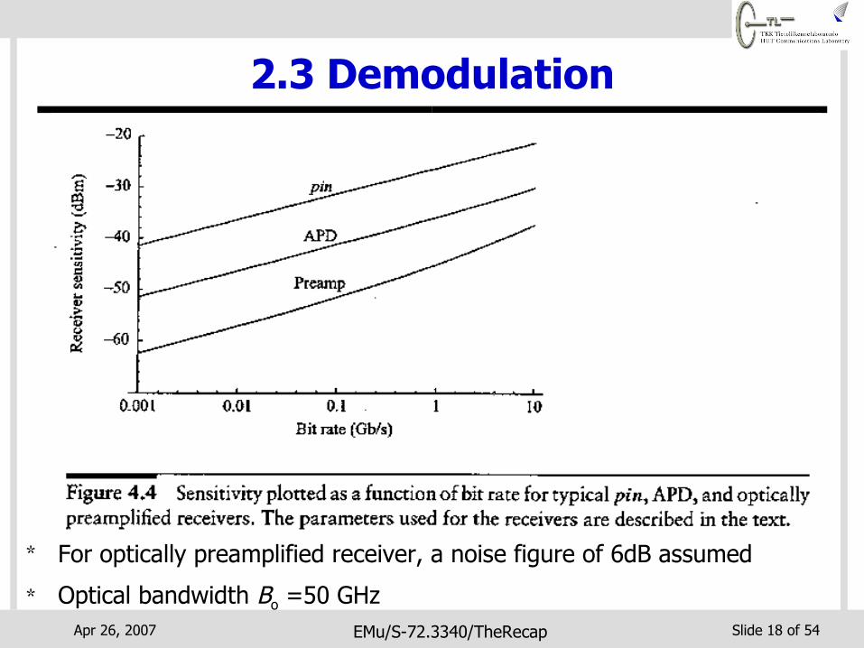
* For optically preamplified receiver, a noise figure of 6dB assumed
* Optical bandwidth Bo =50 GHz
2.3 Demodulation
Apr 26, 2007 EMu/S-72.3340/TheRecap Slide 19 of 54
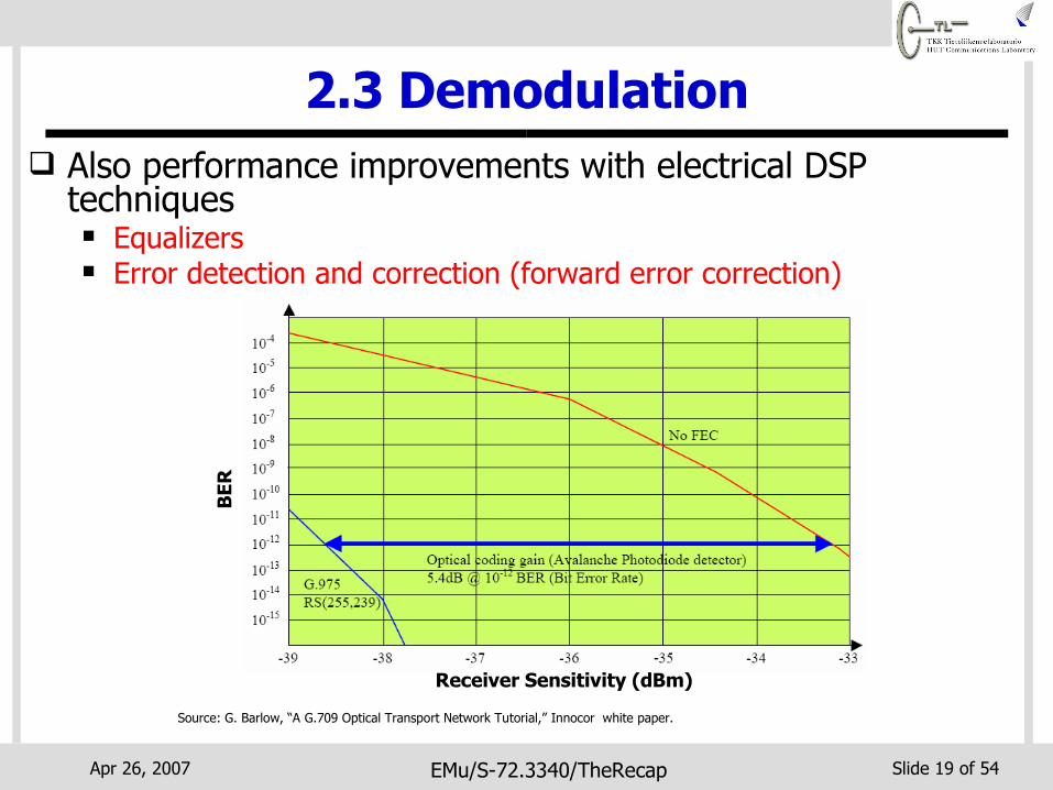
2.3 Demodulation Also performance improvements with electrical DSP
techniques Equalizers Error detection and correction (forward error correction)
Receiver Sensitivity (dBm)
BER
Source: G. Barlow, “A G.709 Optical Transport Network Tutorial,” Innocor white paper.

Apr 26, 2007 EMu/S-72.3340/TheRecap Slide 20 of 54
3. Transmission System Engineering
Link power budget
FiberReceiverReceiverTransmitterTransmitter
dB valueValueItem dB valueValueItem
1a) Average output power
2a) Propagation losses (10 km)
Receiver:3a) Signal power at receiver3b) Receiver sensitivity
Link Margin (Power Margin)
Transmitter:
Channel:
1.0 mW
0.2 dB/km
= (3a – 3b)
0.0 dBm
-20.0 dB
-20.0 dBm-30.0 dBm
+10.0 dB

Apr 26, 2007 EMu/S-72.3340/TheRecap Slide 21 of 54
3. Transmission System Engineering
Power penalty analysis
Received optical power (dBm)
Log(
BER
)
- 31 - 30 - 29 - 28 - 27 - 26 - 25 - 24
- 3
- 4
- 5
- 6
- 7
- 8- 9
- 10- 11- 12- 13- 14- 15- 16
Signal without impairment
Signal with impairment
Power Penalty

Apr 26, 2007 EMu/S-72.3340/TheRecap Slide 22 of 54
3. Transmission System Engineering
Power penalty analysis
Impairment Allocation (dB) Ideal Q-factor 17 Transmitter 1 Crosstalk 1 Dispersion 2 Nonlinearities 1 Polarization dependent losses 3 Component ageing 3 System margin 3 Required Q-factor 31
Apr 26, 2007 EMu/S-72.3340/TheRecap Slide 23 of 54
4. SDH/SONET
Dominant standard for optical transmission and multiplexing for high-speed signals Single master clock ⇒ synchronous multiplexing
• Easier and cheaper multiplexers and demultiplexers
Extensive management information Standard optical interfaces enable interoperability Network topologies and protection switching for high
availability service Basic transmission rates
• SDH ⇒ 155 Mb/s STM-1 (synchronous transport module-1)• SONET ⇒ 51.48 Mb/s (STS-1)

Apr 26, 2007 EMu/S-72.3340/TheRecap Slide 24 of 54
Layer (except physical layer) has associated overhead bytes POH for path layer, MSOH for multiplexer section layer and RSOH for
regenerator section layer
4. SDH/SONET
STM-N frame structure
STM-1 Payload Capacity (VC-4)
POHSOH
261xN Bytes270×N Bytes
9 Row
sRS
OH
MSO
HAU
Po
inte
r

Apr 26, 2007 EMu/S-72.3340/TheRecap Slide 25 of 54
4. SDH/SONET
Regenator Section
Overhead
Multiplexer Section
Overhead
Framing A1
Framing A1
Framing A1
Framing A2
Framing A2
Framing A2
Ident J0
Datacom D1
Sync stat. S1
Growth Z1
Growth Z1
Growth Z2
Growth Z2
Trans err. M1
Orderwire E2
Datacom D2
Datacom D3
Datacom D4
Datacom D5
Datacom D6
Datacom D7
Datacom D8
Datacom D10
Datacom D11
Datacom D12
Datacom D9
APS K1 B2 B2 B2
BIP 24 APS K2
Pointer H1
Pointer H1
Pointer H1
Pointer H2
Pointer H2
Pointer H2
Pointer H3
Pointer H3
Pointer H3
BIP 8 B1
Orderwire E1
User F1
Figure: SDH section overhead bytes. Crossed bytes are auxiliary bytes
AU
P
oin
ter
Automatic Protection Switching
Bit Interleaved
Parity

Apr 26, 2007 EMu/S-72.3340/TheRecap Slide 26 of 54
4. SDH/SONET
VC-11
VC-12
VC-3
STM-1
STM-1
VC-N
DS1
E1
E3
STM-1
STM-N
STM-N
STM-N
VC-N interface
Timeslot Multiplexer
High Speed Interface
VC-12 VC-3 VC-4 STM-N
STM-N bus
E1 E3 E4 STM-N
STM-N STM-NSTM-N TU-12 TU-3 AU-4 STM-NSTM-N
VC-12 VC-3 VC-4 STM-N
Switch Matrix
E1 E3 E4 STM-N
STM-N
STM-N
STM-N
STM-N
STM-NSTM-N
Terminal Multiplexer Add/Drop Multiplexer
Digital Cross-Connect System
Path Terminating Equipment used in the SDH networks

Apr 26, 2007 EMu/S-72.3340/TheRecap Slide 27 of 54
4. SDH/SONETResilient SDH network topologies
TM
Point-to-point configuration
ADM
TM
TM TM
Drop Add
ADM
Drop Add
Linear add/drop configuration
Working fiberProtection fiber
TM: Terminal MultiplexerADM: Add/Drop Multiplexer

Apr 26, 2007 EMu/S-72.3340/TheRecap Slide 28 of 54
4. SDH/SONETResilient SDH network topologies
SNCP ring
Working fiberProtection fiber
ADM
Drop
Add
ADM
Drop
Add
ADM
Drop Add
ADM
Drop Add
ADM
Drop Add
ADM
Drop Add
ADM
Dro
pAd
d
ADM
Dro
pAd
d
TM: Terminal MultiplexerADM: Add/Drop Multiplexer
2-fiber MS-SPRing
ADM
Drop
Add
ADM
Drop
Add
ADM
Drop Add
ADM
Drop Add
ADM
Drop Add
ADM
Drop Add
ADM
Dro
pAd
d
ADM
Dro
pAd
d ADM
Drop
Add
ADM
Drop
Add
ADM
Drop Add
ADM
Drop Add
ADM
Drop Add
ADM
Drop Add
ADM
Dro
pAd
d
ADM
Dro
pAd
d
4-fiber MS-SPRing

Apr 26, 2007 EMu/S-72.3340/TheRecap Slide 29 of 54
5. Multiservice Optical Networks
Multiservice networks provide more than one distinct communications service type Voice, data, Internet etc. Over a common physical infrastructure e.g. fiber
Increased prominence of data-centric protocols ATM, IP/MPLS, Ethernet, SAN protocols etc.
SDH originally defined to carry voice traffic Unsuitable for asynchronous packet-switched bursty data
traffic Four-fold capacity increase increments (e.g. from STM-1
to STM-4) ⇒ Inflexible provision of capacity to users

Apr 26, 2007 EMu/S-72.3340/TheRecap Slide 30 of 54
5. Multiservice Optical NetworksUpgrade current systems with next-generation
SDH/SONET (NG-SDH) solutions Virtual Concatenation (ITU-T G.7043) Link Capacity Adjustment Scheme (ITU-T G.7042) Generic Framing Procedure (ITU-T G.7041)
These upgrades only needed at source and destination terminal equipment of required service Intermediate equipment do not need to be aware and
can interoperate with upgraded equipment Enables operater to make only partial network upgrades
on as-needed basis

Apr 26, 2007 EMu/S-72.3340/TheRecap Slide 31 of 54
5. Multiservice Optical Networks Example ways of transporting IP packets over optical
(WDM) networks via SDH/NG-SDH
IP
10GbE, GbE, Ethernet
Frame-Mapped GFP
Optical (WDM)
Transparent-Mapped GFP
SDH/NG-SDH
DVB, Fiber Channel, ESCON10GbE, AAL5(ATM), PDH PPP/HDLC, PoS
Fiber Link
λ 1
λ 2
λ 3
STM-N
STM-N
Ethernet, IP/MPLSPDH, ATM
FC, FICON, ESCON
DWDM SDH Services
STM-N

Apr 26, 2007 EMu/S-72.3340/TheRecap Slide 32 of 54
5. Multiservice Optical Networks Optical WDM network with open interfaces simplifies direct
access to fiber capacity sharing by different clients
Fiber Link
λ1
λ2
λ3
STM-N
Ethernet
PDH, ATM
IP/MPLS
DWDM Services
Apr 26, 2007 EMu/S-72.3340/TheRecap Slide 33 of 54
5. Multiservice Optical Networks
Optical Transport Network (OTN) ITU-T G.709, G.872 Truly global standard unlike SDH/SONET Enables SDH-like Operations, Administration,
Maintenance and Provisioning for WDM networks• Reduces the requirement to run every service through
SDH/SONET to benefit from the management features
More efficient multiplexing, provisioning, and switching of high-bandwidth (≥ 2.5 Gbit/s) services
Improved multivendor and inter-carrier interoperability Forward error correction (FEC) from the beggining Less complex than NG-SDH ⇒ easier to manage

Apr 26, 2007 EMu/S-72.3340/TheRecap Slide 34 of 54
5. Multiservice Optical NetworksD
igit
al
(ele
ctri
cal)
Opt
ical

Apr 26, 2007 EMu/S-72.3340/TheRecap Slide 35 of 54
5. Multiservice Optical Networks
Supported interfaces Electrical (DS1, E1, E3, STM-1E etc.) SDH (up to STM-64) CWDM and DWDM (OTN) Ethernet (up to GbE) SAN (Fiber Channel and FICON) Video (D1 video, HDTV)
Cross-connection levels DS1/E1 up to STM-64
Cisco ONS 15454
Multiservice provisioning platforms e.g. Cisco’s ONS 15454
Apr 26, 2007 EMu/S-72.3340/TheRecap Slide 36 of 54
5. Multiservice Optical Networks
MSPP
MSPP
MSPP
MSPP
10/100/1000 Mbit/s Ethernet
ATM
Metro Access /Edge
ATM/Ethernet
IP/MPLS
IP/MPLS
10/100/1000 Mbit/s Ethernet
PBX
IP/MPLS
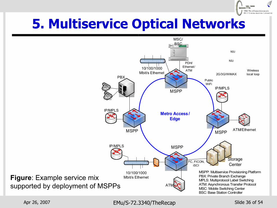
MSPP: Multiservice Provisioning PlatformPBX: Private Branch ExchangeMPLS: Multiprotocol Label SwitchingATM: Asynchronous Transfer ProtocolMSC: Mobile Switching CenterBSC: Base Station Controller
NIU
NIU
MSC/BSC
Storage Center
Public WiFi
2G/3G/WiMAXWireless local loop
PDH/Ethernet/
ATM
FC, FICON, iSCI
Figure: Example service mix supported by deployment of MSPPs

Apr 26, 2007 EMu/S-72.3340/TheRecap Slide 37 of 54
7. Optical Network Design
IP Router
ATM Switch
SDH DigitalCross-Connect
Voice Switch
PSTN
IP/ATMNetworkClient Equipment/
Networks
Optical Node
Optical Network
Open OpticalInterface
FiberLink
A
B
Optical connections

Apr 26, 2007 EMu/S-72.3340/TheRecap Slide 38 of 54
7. Optical Network DesignW
DM
D
EMU
X WD
M
MU
X
Drop(a) Parallel
λ 1 λ 2 …λ W
Add
λ 1
λ 2
λ W
λ 1 λ 2 …λ W
WD
M
DEM
UX W
DM
M
UX
Drop(a) Parallel
λ 1 λ 2 …λ W
Add
λ 1
λ 2
λ W
λ 1 λ 2 …λ W
Example fixed OADM
(b) Fully tunable OADM using a large multiport optical switch
WD
M
DEM
UX W
DM
M
UX
λ 1 λ 2 …λ W
Any λ
λ 1 λ 2 …λ W
Optical switch
Any λAny λ
Any λ
Example reconfigurable OADM
The example OXC scaled to handle 4 wavelength channels on each fiber port
WD
M
DEM
UX
WD
M
MU
Xλ 1 λ 2 λ 3 λ 4
λ 1
λ 2
λ 4
λ 1 λ 2 λ 3 λ 4λ 3
WD
M
DEM
UXλ 1 λ 2 λ 3 λ 4
λ 1
λ 2
λ 4
λ 3
WD
M
MU
X
λ 1 λ 2 λ 3 λ 4
Inpu
t Fi
bers
Out
put
Fibe
rs
Example fixed OXC

Apr 26, 2007 EMu/S-72.3340/TheRecap Slide 39 of 54
7. Optical Network Design A WDM network may be realized by solving:
Physical topology design (PTD) problem Lightpath topology design (LTD) problem Routing and wavelength assignment (RWA) problem
1
4
2
3
A
B
C
D
Solve RWA Problem
1
4
2
3
A
B
C
Dλ 1
λ 2
λ 3
1
4
2
3
A
B
C
Dλ 1
λ 2
λ 3
B
AC
D
B
AC
D
AC
D
1
4
2
3
A
B
C
D
Solve LTD Problem

Apr 26, 2007 EMu/S-72.3340/TheRecap Slide 40 of 54
8. Test and Measurement
Digital Test Modules
SDH (up to STM-64)
PDH
Ethernet (up to 10GbE)
OSA (OSNR, LED/laser/EDFA test)
Q-factor meter
CWDM/DWDM Testing
Source:
Talk set (communication & file transfer)
CD/PMD Testing
OTDR/Power meter
Connection checklist tester
Fiber characterization
Software tools (result post-processing, report generation)
Example: Acterna MTS-8000 Tester

Apr 26, 2007 EMu/S-72.3340/TheRecap Slide 41 of 54
8. Test and Measurement
Figure: Example OTDR measurement for a fiber link to customers’ optical termination unit (ONU) Source: “Introduction to Optical Communications,” by L. Hart, Althos Publishing

Apr 26, 2007 EMu/S-72.3340/TheRecap Slide 42 of 54
9. Network Management and Survivability
Subnetwork connection protection (SNCP) rings
SNCP ring
Working fiberProtection fiber
ADM
Drop
Add
ADM
Drop Add
ADM
Drop Add
ADM
Dro
pAd
d
Working traffic
Before Failure
SNCP ring
ADM
Drop
Add
ADM
Drop Add
ADM
Drop Add
ADM
Dro
pAd
d
After Failure
Traffic on protection fiber selected
Duplicate traffic

Apr 26, 2007 EMu/S-72.3340/TheRecap Slide 43 of 54
9. Network Management and Survivability
IP/MPLS network protection schemes When failure detected packets could be rerouted on new
setup LSP
LSR
LSR
LSRPenultimate
LSRIngress
LER
Egress LSR
LSPLER: Label Edge RouterLSR: Label Switched-RouterLSP Label Switched Path
Customer Site A
Customer Site B
IP/MPLS Network
New LSP

Apr 26, 2007 EMu/S-72.3340/TheRecap Slide 44 of 54
9. Network Management and Survivability
OXC
Fiber
OXC
OXC
OXC
SDH ADM 1
(a) Normal operation before failure. SDH connection realized using lightpaths provided by optical layer between ADMs
SDH ADM 3
SDH connectionLightpath
SDH
AD
M 4 SD
H
ADM
2
Example of SDH protection involving optical layer
OXC
OXC
OXC
OXC
SDH ADM 1
SDH ADM 3
SDH
AD
M 4 SD
H
ADM
2
(c) Fiber fails and OXCs perform optical layer restoration and reroute lightpath. SDH carries on with normal operation awaiting another failure

Apr 26, 2007 EMu/S-72.3340/TheRecap Slide 45 of 54
9. Network Management and Survivability
Classical network management constitutes “FCAPS” functions Fault management: detecting failures and isolating failed component Configuration management: managing orderly network changes e.g.
equipment addition/removal Accounting management: billing and developing component lifetime
histories Performance management: monitoring and managing various
network performance metrics Security management: user authentication, control access to
network elements, user data protection etc. Safety management: (specifically for optical networks) ensure that
optical radiation conforms to eye safety requirements.

Apr 26, 2007 EMu/S-72.3340/TheRecap Slide 46 of 54
9. Network Management and Survivability
Optical Node 1
Interaction between optical and client layers (IP, SDH etc.) is important aspect of connection management protocols
Different control plane models proposed for interconnecting optical layer control plane and client layer control plane Overlay model Overlay+ model Augmented (dynamic overlay) model Peer model
IP router A
IP router B
Optical Node 2
IP connection provided via lightpath in optical layer
Fiber
Figure: Example of client layer connection provision via the optical layer

Apr 26, 2007 EMu/S-72.3340/TheRecap Slide 47 of 54
10. Deployment Considerations Selected fiber cable deployment method depends on various
factors Geographical topography of an area Availability of rights-of-way Time constraints Operator’s business strategy
Figure: Fiber cables deployed on power transmission lines (source: Alcatel)
Figure: Fiber cables deployed on power transmission lines (source: Alcatel)

Apr 26, 2007 EMu/S-72.3340/TheRecap Slide 48 of 54
10. Deployment Considerations
Apr 26, 2007 EMu/S-72.3340/TheRecap Slide 49 of 54
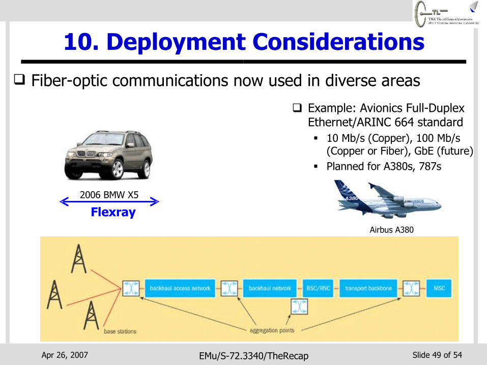
10. Deployment Considerations
2006 BMW X5
Flexray
Example: Avionics Full-Duplex Ethernet/ARINC 664 standard 10 Mb/s (Copper), 100 Mb/s
(Copper or Fiber), GbE (future) Planned for A380s, 787s
Airbus A380
Fiber-optic communications now used in diverse areas
Apr 26, 2007 EMu/S-72.3340/TheRecap Slide 50 of 54
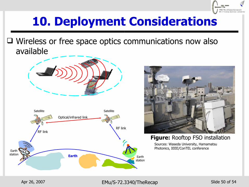
10. Deployment Considerations Wireless or free space optics communications now also
available
Sources: Waseda University, Hamamatsu Photonics, IEEE/ConTEL conference
Figure: Rooftop FSO installation
Earth
RF linkRF link
Optical/infrared link
Satellite Satellite
Earthstation
Earthstation

Apr 26, 2007 EMu/S-72.3340/TheRecap Slide 51 of 54
11. Future Directions of Optical Net.
*Ref: J. Kahn & K. Ho, Proceedings of SPIE, Vol. 4872, July 2005
(Cap
acit
y x
Dis
tan
ce)/
Cos
t
Time
Optical Amplifiers
-
Optical Technologies
Non-Optical Technologies
WDM
FDM/SCM
Compensation
Adaptive Threshold, Transversal Filters
Error-Correction Coding
Non-Binary Modulation
Current Optical Comm. Systems
Adaptive Equalization
Coded Modulation
(Cap
acit
y x
Dis
tan
ce)/
Cos
t
Time
Optical Amplifiers
OEO Transponders
-
Optical Technologies
Non-Optical Technologies
WDM
FDM/SCM
Optical Dispersion
Adaptive Threshold, Transversal Filters
Error-Correction Coding
Non-Binary Modulation
Current Optical Comm. Systems
Adaptive Equalization
Coded Modulation
Apr 26, 2007 EMu/S-72.3340/TheRecap Slide 52 of 54
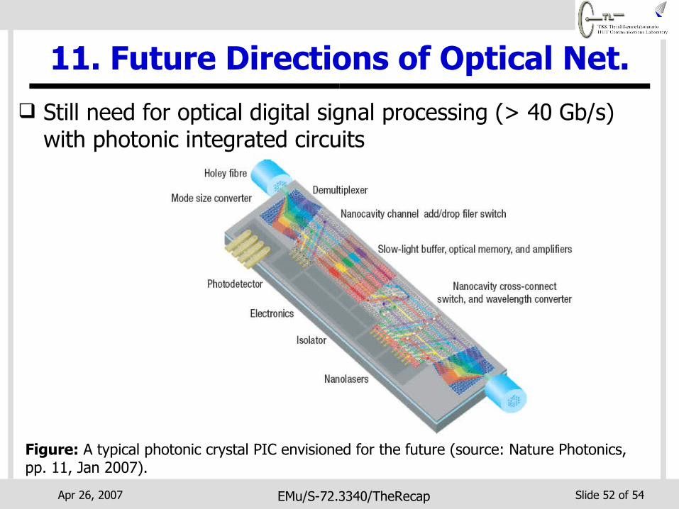
11. Future Directions of Optical Net. Still need for optical digital signal processing (> 40 Gb/s)
with photonic integrated circuits
Figure: A typical photonic crystal PIC envisioned for the future (source: Nature Photonics, pp. 11, Jan 2007).

Apr 26, 2007 EMu/S-72.3340/TheRecap Slide 53 of 54
About the Exam
Please note that YOU CAN ONLY DO ONE(1) EXAM. That is if you do Exam A, you will not do Exam B, OR if you do Exam B you will not do Exam A. Exam A: Day: Ma/Mon 14.05.2007, Time: 13-16,
Place: S1,S4 Exam B: Day: Ke/Wed 16.05.2007, Time: 16-19,
Place: S4 Each exam will have five questions, whereby
Question 1 is compulsory, and you can choose to do any three out of Questions 2 to 5.

Apr 26, 2007 EMu/S-72.3340/TheRecap Slide 54 of 54
?Thank You and Good luck!

![M2M Traffic via Random Access Satellite links: Interactions ... · of RA for the efficient transport of M2M services via satellite are provided in [2], [3]. The use of satellites](https://static.fdocuments.us/doc/165x107/5fc966303a90dd044f45bc4f/m2m-trafic-via-random-access-satellite-links-interactions-of-ra-for-the-eficient.jpg)