RXVK 2H and RAVK User´s Guide Thermal overcurrent relay … · 2015-05-18 · 1.2 Determining the...
34
ABB Network Partner AB General When the load current exceeds the permitted continuous current there is a risk that conductors and insulations will be damaged due to overheating. The thermal overcurrent protection RAVK effectively prevents such damage and, at the same time, allows full utilization of the protected object. The COMBIFLEX thermal protection RAVK is primarily used for thermal protection of motors, generators, transformers, cables and reactors. However, it is designed to meet the requirements for thermal protections in most power system applications. For the general thermal application a very wide setting ranges is available with this relay, obviating the need to specify different versions depending on the protective applications. RAVK is available as single-phase, two-phase and three-phase thermal protection with one measuring relay RXVK 2H per phase. Rated current is 1 A or 5 A. RXVK 2H is a micro-processor based relay with one thermal overload and one time-overcurrent stage. Setting range for the thermal stage is 0,05-1,5 times rated current and thermal time constant T=2-62 minutes. For the time-overcurrent stage the setting range is 0,05-20 times rated current and 0,03 - 5 s. All RAVK protections are: • mounted in the COMBIFLEX modularised system • available with or without test switch • available with or without DC-DC converter • available with or without additional heavy duty tripping relay RXVK 2H and RAVK Thermal overcurrent relay and protection assemblies 1MRK 509 003-UEN Version 1 October 1997 User´s Guide
Transcript of RXVK 2H and RAVK User´s Guide Thermal overcurrent relay … · 2015-05-18 · 1.2 Determining the...

ABB Network Partner AB
General
When the load current exceeds the permitted continuous current there is a risk that conductors and insulationswill be damaged due to overheating. The thermal overcurrent protection RAVK effectively prevents such damageand, at the same time, allows full utilization of the protected object.
The COMBIFLEX thermal protection RAVK is primarily used for thermal protection of motors, generators,transformers, cables and reactors. However, it is designed to meet the requirements for thermal protections inmost power system applications. For the general thermal application a very wide setting ranges is available withthis relay, obviating the need to specify different versions depending on the protective applications.
RAVK is available as single-phase, two-phase and three-phase thermal protection with one measuring relayRXVK 2H per phase. Rated current is 1 A or 5 A. RXVK 2H is a micro-processor based relay with one thermaloverload and one time-overcurrent stage. Setting range for the thermal stage is 0,05-1,5 times rated current andthermal time constant T=2-62 minutes. For the time-overcurrent stage the setting range is 0,05-20 times ratedcurrent and 0,03 - 5 s.
All RAVK protections are:• mounted in the COMBIFLEX modularised system• available with or without test switch• available with or without DC-DC converter • available with or without additional heavy duty tripping relay
RXVK 2H and RAVKThermal overcurrent relay and protection assemblies
1MRK 509 003-UENVersion 1October 1997
User´s Guide

ABB Network Partner ABRXVK and RAVKThermal overcurrent relay and protection assemblies Version 1
October 1997
1MRK 509 003-UENPage 2
List of contents1 Application.................................................................................. 31.1 Settings......................................................................................... 51.2 Determining the time constant ..................................................... 7
2 Measurement principles ............................................................ 8
3 Design ........................................................................................ 103.1 Test switch ................................................................................. 103.2 DC-DC converter ....................................................................... 103.3 Measuring relay.......................................................................... 103.4 Tripping relay............................................................................. 11
4 Setting and connection............................................................. 124.1 Connection ................................................................................. 124.2 Settings....................................................................................... 134.3 Indication ................................................................................... 144.4 Tripping and start outputs .......................................................... 144.5 ESD ............................................................................................ 14
5 Technical data for thermal overcurrent relay RXVK 2H.... 15
6 Receiving, Handling and Storage ........................................... 196.1 Receiving and Handling............................................................. 196.2 Storage ....................................................................................... 19
7 Installation, Testing and Commissioning............................... 207.1 Installation.................................................................................. 207.2 Testing........................................................................................ 237.3 Commissioning .......................................................................... 25
8 Maintenance ............................................................................. 26
9 Circuit and terminal diagrams ............................................... 27

RXVK and RAVKThermal overcurrent relay and protection assemblies
ABB Network Partner AB 1MRK 509 003-UENPage 3
Version 1October 1997
1 ApplicationAll electrical conductors have a certain resistance, which gives rise to anactive power loss I2 · r, where I is the rms value of the current and r is theresistance of the conductor. Hence the active power loss is proportional tothe square of the current and inversely proportional to the crossectionalarea of the conductor.
The phase current conductors in cables, motors, generators, transformers,reactors etc. are surrounded by insulating material which deteriorates rap-idly if the temperature exceeds the design limit value. As a rule of thethumb, the useful life time of the insulation material will be reduced tothe half of the design value for each continuous increment of the tempera-ture of the conductor by 7 degrees centigrade above rated value.
The temperature rise of a body which is heated from a source of constantenergy is according to the equation:
equation 1
When the heat energy is decreased, the following is valid:
equation 2
where θ(t) = the temperature rise of the body as a function of time
θs = the final, steady state temperature rise
θb= the temperature rise at the moment when the power is increased
θ0 = the temperature rise at the moment when the power is reduced
θs2 = the final, steady-state temperature rise corresponding to the reducedpower
τ = the thermal time constant
Fig. 1 shows the temperature rise as function of time when a conductorcarries current which gives a final temperature rise of θs. Fig. 2 shows thecorresponding rise of temperature when the conductor carries a load = 1,5times this current.
θ t( ) θs θs θb–( )– e t Τ/–=
θ t( ) θs2 θ0 θs2–( )+ e t Τ/– =

ABB Network Partner ABRXVK and RAVKThermal overcurrent relay and protection assemblies Version 1
October 1997
1MRK 509 003-UENPage 4
Fig. 1 Temperature rise at rated current
Fig. 2 Temperature rise at 1,5 x rated current
12 3
0,63
1
Time
(t/τ)0
τ
θ/θs
4
1 2 3
1
2
2,25
Time
(t/τ)00
0,6 τ
θ/θs

RXVK and RAVKThermal overcurrent relay and protection assemblies
ABB Network Partner AB 1MRK 509 003-UENPage 5
Version 1October 1997
Overloads up to 1,4 times rated current are normally not detected by theshort-circuit overcurrent or impedance relays. A sustained overload of1,2 times rated current gives a temperature increase of 1,22 = 1,44 timesthe temperature increase at rated current. For large generators, motors,transformers and reactors, thermal overloading of the windings will bedetected by temperature monitors. For apparatuses without thermal detec-tors, an accurate thermal relay with operating characteristics giving a ther-mal replica of the winding will provide a thermal overload protection. Forapparatuses with thermal detectors, a thermal overcurrent relay will pro-vide a back-up function.
Electrical cables which can be loaded up to the permissible thermal loadcurrent should be provided with both thermal and short-circuit protection.For cables surrounded by air, the thermal time constant τ can vary fromsome few minutes for 10 kV cables with cross-sectional area 25 mm2 toone hour for 30 kV cables with cross-sectional area > 185 mm2.
The shorter time constant valid for cables placed in air will normally bedecisive, since some part of the cable normally will be surrounded by air.
1.1 Settings The thermal overcurrent relay RXVK 2H has time-current characteristicswhich follows the equation:
where I = overload current
Ip = current previous to the overload, assuming sufficient long time toreach steady-state temperature
Ib = rated current
k = security factor = 1,01
The security factor means that the start current Ib of the relay can be setequal to the maximum permissible continuous load current. If no securityfactor were included, the relay would trip for rated current after long time.
It should be observed, that the start relay for the thermal stage operates at1,01 · Ib and that a final, steady-state temperature giving tripping isobtained for a continuous current equal to 1,01 · Ib.
The current-time operate characteristics of the relay is identical to equa-tions 1 and 2 above when the final temperature increase θs is set to corre-spond to a current equal to 1,01 · Ib.
The current-time curves in Fig. 3 show the operate time for currents whichare given as multiples of the set start current Ib.
t τ ln I2
Ip2
–
I2
k2
Ib2⋅( )–
-------------------------------⋅=

ABB Network Partner ABRXVK and RAVKThermal overcurrent relay and protection assemblies Version 1
October 1997
1MRK 509 003-UENPage 6
Fig. 3 Operate-time curves of thermal protection RAVK.
t/τ
10
0.0001 xI/Ib1 10
Ip=
00.50.60.70.80.9
1.0
RXVK Ip curves
32 4 5 6 7 8 90
0.001
0.01
0.1
1

RXVK and RAVKThermal overcurrent relay and protection assemblies
ABB Network Partner AB 1MRK 509 003-UENPage 7
Version 1October 1997
1.2 Determining the time constant
In some cases, the current-time capability curve is given instead of thethermal time constant τ. A suitable τ−setting then must be decided bycomparing some points on the capability curve with the operate-timecurves of RAVK. If the capability curve deviates from the relay operatecurve, the lowest value of τ is selected.
Example: The thermal overload curve for a cold motor shows that 1,5times rated load current is permissible for 18 minutes and 5 times ratedcurrent is permissible for 1 minute. From the relay operate curve, it is seenthat the operate time is 0,6 · τ at 1,5 times and 0,04 · τ at 5 times rated cur-rent for a cold motor.
Hence, the τ calculated from those two points would be 18min/0,6 = 30minutes respectively 1 minute/0,04 = 25 minutes. The lowest value shouldbe selected for the relay.
The accurate values can be calculated from the formula given inSection 1.1.

ABB Network Partner ABRXVK and RAVKThermal overcurrent relay and protection assemblies Version 1
October 1997
1MRK 509 003-UENPage 8
2 Measurement principlesThe RXVK 2H relay constitutes the measuring unit of RAVK. For settingof operate values and the functions of the output relays and the LEDs, seeSection 4.
The functional diagram in fig. 4 illustrates the mode of operating of theRXVK 2H relay.
To provide a suitable voltage for the electronic measurement circuit, therelay is provided with an input transformer. The output current of thetransformer is shunted via dip-switches before it is filtered with a 4thorder bandpass filter with a centre frequency of 55 Hz. The relay can alsobe ordered with a filter for suppressing frequency dependence 40-2000 Hz, see Section 5.
The voltage is rectified before it is sampled with a sample rate of 1000samples/s. The voltage ripple is reduced with a moving average filter.
The thermal stage operates when the accumulated thermal content (θ) hasreached the set operate thermal value (Ib x k)2 where k is equal to 1,01.The accumulated thermal content increases or decreases with (I2 − θ)/(τ x60) per second. The thermal content is updated every 12 ms. The resultingoperate characteristic in accordance with the equation:
where Ip is the preload current before overload.
The over-current stage I> operates when the current reaches the set oper-ate current. The I> stage is provided with a definite-time delay.
Fig. 4 Functional diagram illustrating the mode of operating of the RXVK 2H relay
t τ=I2
Ip2
–
I2
Ib k⋅( )2
–-------------------------------ln⋅
trip
trip
trip
trip
Ib
00000
248
1632
Θ >95%
Θ
I>
Θ
Θ
I>
start I> TimeI>
I>t
τ
θ Θ >95%
Binary input
LED LED+θ bin reset
LED LED+θ man reset
&
&
≥1
reset
Θ trip
>95%
Reset

RXVK and RAVKThermal overcurrent relay and protection assemblies
ABB Network Partner AB 1MRK 509 003-UENPage 9
Version 1October 1997
Resetting of the thermal content can be made with either the reset buttonor the binary input. When switch 9 is set to “LED+θ man reset” the resetbutton resets the thermal content when it is depressed. When switch 10 isset to “LED+θ bin reset” the binary input resets the thermal content whenactivated. The binary input is galvanically separated from the electronicmeasurement circuits with an opto-coupler.
The reset button also resets the LEDs and makes it possible for the opera-tor to check the LEDs. When the button is depressed, the “θ > 95%”,“θ Trip” and “I> Trip” LEDs are lit and the “In serv.” LED is switchedoff, in order to check the LEDs. When the button is released, the“θ > 95%”, “θ Trip” and “I> Trip” LEDs are reset to show the actual sta-tus and the “In serv.” LED is relit. If the reset button is depressed whilethe “θ Trip” function is operating and the thermal content is decreasing,the “θ Trip” LED will be reset when the thermal content is below 80%.
When the processor starts it executes a self test sequence. If the processorfails to start in a proper way the LEDs will indicate by flashing accordingto fig. 5 or the “In serv.” LED will not be lit. The program in the micro-processor is executed in a fixed loop with a constant loop time. The loopis supervised by an internal watchdog which initiates a program restart ifthe program malfunctions.
Fig. 5 Self test error indication of the RXVK 2H relay
Test sequence: Test error indication:
Config. registers All LEDs flash inclockwise rotation.
RAM “θ Trip” flashes.ROM “I> Trip” flashes.A/D “θ Trip” and “I> Trip” flash.
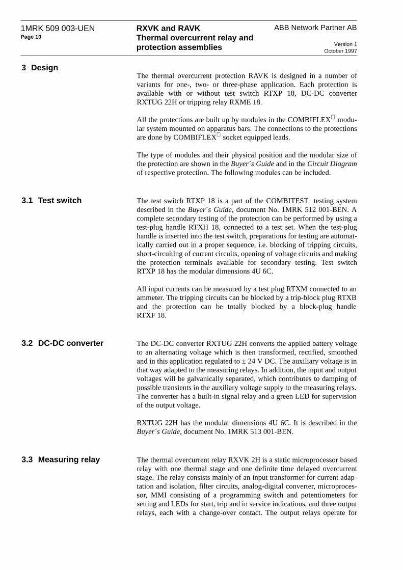
ABB Network Partner ABRXVK and RAVKThermal overcurrent relay and protection assemblies Version 1
October 1997
1MRK 509 003-UENPage 10
3 DesignThe thermal overcurrent protection RAVK is designed in a number ofvariants for one-, two- or three-phase application. Each protection isavailable with or without test switch RTXP 18, DC-DC converterRXTUG 22H or tripping relay RXME 18.
All the protections are built up by modules in the COMBIFLEX modu-lar system mounted on apparatus bars. The connections to the protectionsare done by COMBIFLEX socket equipped leads.
The type of modules and their physical position and the modular size ofthe protection are shown in the Buyer´s Guide and in the Circuit Diagramof respective protection. The following modules can be included.
3.1 Test switch The test switch RTXP 18 is a part of the COMBITEST testing systemdescribed in the Buyer´s Guide, document No. 1MRK 512 001-BEN. Acomplete secondary testing of the protection can be performed by using atest-plug handle RTXH 18, connected to a test set. When the test-plughandle is inserted into the test switch, preparations for testing are automat-ically carried out in a proper sequence, i.e. blocking of tripping circuits,short-circuiting of current circuits, opening of voltage circuits and makingthe protection terminals available for secondary testing. Test switchRTXP 18 has the modular dimensions 4U 6C.
All input currents can be measured by a test plug RTXM connected to anammeter. The tripping circuits can be blocked by a trip-block plug RTXBand the protection can be totally blocked by a block-plug handleRTXF 18.
3.2 DC-DC converter The DC-DC converter RXTUG 22H converts the applied battery voltageto an alternating voltage which is then transformed, rectified, smoothedand in this application regulated to ± 24 V DC. The auxiliary voltage is inthat way adapted to the measuring relays. In addition, the input and outputvoltages will be galvanically separated, which contributes to damping ofpossible transients in the auxiliary voltage supply to the measuring relays.The converter has a built-in signal relay and a green LED for supervisionof the output voltage.
RXTUG 22H has the modular dimensions 4U 6C. It is described in theBuyer´s Guide, document No. 1MRK 513 001-BEN.
3.3 Measuring relay The thermal overcurrent relay RXVK 2H is a static microprocessor basedrelay with one thermal stage and one definite time delayed overcurrentstage. The relay consists mainly of an input transformer for current adap-tation and isolation, filter circuits, analog-digital converter, microproces-sor, MMI consisting of a programming switch and potentiometers forsetting and LEDs for start, trip and in service indications, and three outputrelays, each with a change-over contact. The output relays operate for

RXVK and RAVKThermal overcurrent relay and protection assemblies
ABB Network Partner AB 1MRK 509 003-UENPage 11
Version 1October 1997
thermal overload, overcurrent and when the thermal content exceeds95 % of set thermal operate value. The relay has also a binary input forremote resetting of the LEDs or the LEDs and the thermal content.
There are two variants of the relay with regard to rated currents and twovariants with regard to frequency characteristics. Operate values of thethermal and the overcurrent functions are set by potentiometers and pro-gramming switches in the front.
RXVK 2H has the modular dimensions 4U 6C.
3.4 Tripping relay The auxiliary relay RXME 18 is used as a tripping relay. It has two heavyduty make contacts and a red flag. The flag will be visible when the arma-ture picks-up and is manually reset by a knob in the front of the relay.Typical operate time is 35 ms.
RXME 18 has the modular dimensions 2U 6C. The relay is described inthe Buyer´s Guide, document No. 1MRK 508 015-BEN.

ABB Network Partner ABRXVK and RAVKThermal overcurrent relay and protection assemblies Version 1
October 1997
1MRK 509 003-UENPage 12
4 Setting and connection
Rated current of the relay, Ir (available variants: 1 A or 5 A)
LED indicators:In serv. (green): indicates relay in service.Start (yellow): indicates operation of Θ>95% (no time delay).Θ Trip (red): indicates operation of Θ after the set time delay.I> Trip(red): indicates operation of I> after the set time delay.
(Thermal stage):
Potentiometer (P1) for setting of the thermal stage base current Ib.
10-pole programming switch (S1) for setting of the scale-constant Is, timeconstant τ and the binary input function.
I> (Overcurrent stage):
Potentiometer (P2) for setting of the operate value for the function I>.
Potentiometer (P3) for setting of the definite time-delay t for thefunction I>.
Reset push-button.
Fig. 6 Front layout
4.1 Connection The RXVK 2H relay requires a dc-dc converter type RXTUG for auxil-iary voltage supply +24 V. Connection of voltage RL shall be made onlywhen the binary input is used.
The relay is delivered with a short-circuiting connector RTXK for mount-ing on the rear of the terminal base. This connector will automaticallyshort-circuit the current input when the relay is removed from its terminalbase.
NOTE! The auxiliary voltage supply should be interrupted or the outputcircuits should be blocked to avoid the risk of unwanted alarm or tripping,before the relay is plugged into or withdrawn from its terminal base.
1MRK 000 117-38

RXVK and RAVKThermal overcurrent relay and protection assemblies
ABB Network Partner AB 1MRK 509 003-UENPage 13
Version 1October 1997
Fig. 7 Terminal diagram
4.2 Settings All settings can be changed while the relay is in normal service.
1. Setting of the scale-constant Is.Is is common for both the thermal stage and the overcurrent stage I>.
It is set with the programming switches S1:1, S1:2 and S1:3, from 0,1 to1,0 × the rated current Ir.
2 Setting of the thermal stage base current Ib.The base current is set with potentiometer P1 according to Ib = P1 × Is.
3. The thermal stage time constant.The thermal stage time constant, τ, is programmable from 2 to 62 minutesin steps of two minutes on the programming switches S1:4 to S1:8. (τ = Σ(min)). The operate time is determined by the setting of the base current Iband the selected time constant τ.
4. Setting of the overcurrent stage I> operate value.The operate value is set with potentiometer P2 according to I> = P2 × Is.This function can be blocked by setting potentiometer P2 to ”∞".
5. The overcurrent stage time delay.The time delay for the overcurrent stage (I>) has definite-time characteris-tic. The minimum value is 30 ms and the maximum value is 5 s. The settingis done with potentiometer P3.
6. The binary input.The binary input is programmable for either remote reset of the LED indi-cators, or remote reset of the LED indicators and the thermal content of therelay. The function is activated when a voltage RL is applied to the binaryinput. The setting is done on the programming switch S1:10.
7. Manual reset.The reset push-button is programmable for either reset of the LED indica-tors, or reset of the LED indicators and the thermal content of the relay.This setting is done on the programming switch S1:9.
124
125
126
331
341
116
110-220V
48-60V
0V
Θ>95%
Θ
I>
I
113 114 115
+24V 0V -24V
326328
327
RL
323325
324
316318
317

ABB Network Partner ABRXVK and RAVKThermal overcurrent relay and protection assemblies Version 1
October 1997
1MRK 509 003-UENPage 14
4.3 Indication There are four LED indicators. The trip indicators seal-in and are resetmanually by the ”Reset” push-button or electrically via the binary input,while the start indicator resets automatically when the relay resets.
When the ”Reset” push-button is depressed during normal operating con-ditions, all LEDs except "In serv." will light up.
When connecting RXVK 2H to the auxiliary voltage, the relay performs aself test. The ”In serv.” LED is alight, after performing the self test andwhen the relay is ready for operation. In case of a fault, the LEDs will startflashing.
4.4 Tripping and start outputs
The RXVK 2H relay has one start and one tripping output for the thermalstage, and one trip output for the overcurrent stage. Each output is providedwith one change-over contact. All outputs reset automatically when thecurrent decreases to a value below the resetting value of the relay.
4.5 ESD The relay contains electronic circuits which can be damaged if exposed tostatic electricity. Always avoid to touch the circuit board when the relaycover is removed during the setting procedure.
RXVK and RAVKThermal overcurrent relay and protection assemblies
ABB Network Partner AB 1MRK 509 003-UENPage 15
Version 1October 1997
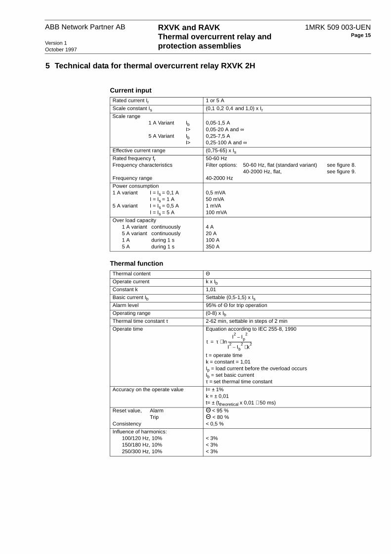
5 Technical data for thermal overcurrent relay RXVK 2H
Current inputRated current Ir 1 or 5 A
Scale constant Is (0,1 0,2 0,4 and 1,0) x Ir
Scale range1 A Variant Ib
I>5 A Variant Ib
I>
0,05-1,5 A0,05-20 A and ∞0,25-7,5 A0,25-100 A and ∞
Effective current range (0,75-65) x IsRated frequency frFrequency characteristics
Frequency range
50-60 HzFilter options: 50-60 Hz, flat (standard variant) see figure 8.
40-2000 Hz, flat, see figure 9.40-2000 Hz
Power consumption 1 A variant I = Is = 0,1 A
I = Is = 1 A5 A variant I = Is = 0,5 A
I = Is = 5 A
0,5 mVA50 mVA1 mVA100 mVA
Over load capacity1 A variant continuously5 A variant continuously1 A during 1 s5 A during 1 s
4 A20 A100 A350 A
Thermal functionThermal content ΘOperate current k x IbConstant k 1,01
Basic current Ib Settable (0,5-1,5) x IsAlarm level 95% of Θ for trip operation
Operating range (0-8) x IbThermal time constant τ 2-62 min, settable in steps of 2 min
Operate time Equation according to IEC 255-8, 1990
t = operate timek = constant = 1,01Ip = load current before the overload occursIb = set basic currentτ = set thermal time constant
Accuracy on the operate value I= ± 1%k = ± 0,01t= ± (ttheoretical x 0,01 + 50 ms)
Reset value, AlarmTrip
Consistency
Θ < 95 %Θ < 80 %< 0,5 %
Influence of harmonics:100/120 Hz, 10%150/180 Hz, 10%250/300 Hz, 10%
< 3%< 3%< 3%
t τI2
Ip2
–
I2
Ib2
k2⋅–
---------------------------ln⋅=

ABB Network Partner ABRXVK and RAVKThermal overcurrent relay and protection assemblies Version 1
October 1997
1MRK 509 003-UENPage 16
Over-current functionRXVK 2H 50-60 Hz, standard filter 40-2000 Hz, flat filter
Setting range I > (0,5-20) x Is and ∞Setting range for time delayAccuracy
0,03-5 s1% and ±10 ms
Operate time (typical)I = 0 => 1,3 x I> I = 0 => 3 x I> I = 0 => 10 x I>
Time delay = 0,03 s35 ms25 ms20 ms
Reset time (typical)I = 3 => 0 x I> I = 20 => 0 x I>
35 ms60 ms
Reset ratio (typical)Consistency
95%< 1,5%
Transient over-reach L/R=10,50 and 100 ms < 5 % < 20 %
Operate value at 150 Hz App. 1,5 x set op. value –
Operate value within the range40-2000 Hz – < 1,1 x set op. value
Overshoot time < 20 ms
Recovery time at I = 3 x I> < 40 ms
Influence of harmonics:100/120 Hz, 10%150/180 Hz, 10%250/300 Hz, 10%
< 3%< 3%< 3%
–––
Auxiliary DC voltage supplyAuxiliary voltage EL for RXTUG 22HAuxiliary voltage to the relay
24-250 V DC, ±20%±24 V (from RXTUG 22H)
Power consumption at RXTUG 22H input24-250 V before operation
after operationwithout RXTUG 22H
±24 V before operation after operation
Standard other filterMax. 4,5 W Max. 5,5 WMax. 6,0 W Max. 6,5 W
Max. 1,3 W Max. 2,0 WMax. 3,0 W Max. 3,0 W
Binary inputBinary input voltage RL 48-60 V and 110-220 V DC, -20% to +10%
Power consumption 48-60 V110-220 V
Max. 0,3 WMax. 1,5 W
Output relaysContacts 3 change-over
Maximum system voltage 250 V AC / DC.
Current carrying capacitycontinuousduring 1 s
5 A15 A
Making capacity at inductive load with L/R >10 msduring 200 msduring 1 s
30 A10 A
Breaking capacityAC, max. 250 V, cos ϕ > 0,4DC, with L/R < 40 ms 48 V
110 V220 V250 V
8 A1 A0,4 A0,2 A0,15 A

RXVK and RAVKThermal overcurrent relay and protection assemblies
ABB Network Partner AB 1MRK 509 003-UENPage 17
Version 1October 1997
Electromagnetic compatibility (EMC), immunity testsAll tests are done together with the DC/DC-converter, RXTUG 22H
Test Severity Standard
Surge 1 and 2 kV, normal service2 and 4 kV, destructive test
IEC 61000-4-5, class 3IEC 61000-4-5, class 4
AC injection 500 V, AC SS 436 15 03, PL 4
Power frequency magnetic field 1000 A/m IEC 61000-4-8
1 MHz burst 2,5 kV IEC 60255-22-1, class 3
Spark 4-8 kV SS 436 15 03, PL 4
Fast transient 4 kV IEC 60255-22-4, class 4
Electrostatic discharge In normal service with cover on 8 kV (contact)
15 kV (air)8 kV, indirect application
IEC 60255-22-2, class 4IEC 60255-22-2, class 4IEC 61000-4-2, class 4
Radiated electromagnetic field 10 V/m, 26-1000 MHz IEC 61000-4-3, level 3
Conducted electromagnetic 10 V, 0,15-80 MHz IEC 61000-4-6, level 3
Interruptions in auxiliary voltage110 V DC, no resetting for interrup-tions
2-200 ms< 40 ms
IEC 60255-11
Electromagnetic compatibility (EMC), emission testsTest Severity Standard
Conducted 0,15-30 MHz, class A EN 50081- 2
Radiated 30-1000 MHz, class A EN 50081- 2
Insulation testsTest Severity Standard
Dielectriccurrent circuitother circuitsover open contact
2,5 kV AC, 1 min2,0 kV AC, 1 min1,0 kV AC, 1 min
IEC 60255-5
Impulse voltage 5 kV, 1,2/50 µs, 0,5 J IEC 60255-5
Insulation resistance > 100 MΩ at 500 V DC IEC 60255-5
Mechanical testsTest Severity Standard
Vibration Response: 2,0 g, 10-150-10 HzEndurance: 1,0 g, 10-150-10 Hz, 20 sweeps
IEC 60255-21-1, class 2IEC 60255-21-1, class 1
Shock Response: 5 g, 11 ms, 3 pulsesWithstand: 15 g, 11 ms, 3 pulses
IEC 60255-21-2, class 1
Bump Withstand: 10 g, 16 ms, 1000 pulses IEC 60255-21-2, class 1
Seismic X axis: 3,0 g, 1-35-1 HzY axis: 3,0 g, 1-35-1 HzZ axis: 2,0 g, 1-35-1 Hz
IEC 60255-21-3, class 2, extended (Method A)
Temperature rangeStorage -20 °C to +70 °C
Permitted ambient temperature -5 °C to +55 °C
Weight and dimensionsEquipment Weight Height Width
RXVK 2H without RXTUG 22H 0,7 kg 4U 6C

ABB Network Partner ABRXVK and RAVKThermal overcurrent relay and protection assemblies Version 1
October 1997
1MRK 509 003-UENPage 18
Fig. 8 Typical frequency characteristic for RXVK 50-60 Hz, standard, valid for valid for I ≤ 65 x Is.
Fig. 9 Typical frequency characteristic for RXVK 40-2000 Hz, flat, valid for valid for I ≤ 65 x Is.
1
2
10
3
40 50 60 100 1000300 500150 180
4
5
6
789
Frequency
Operate current/set operate current
1,00
1,05
40 50 60 100 2000500 1000200 3000,95
1,10
1,20
400
1,15
Frequency
Operate current / set operate current

RXVK and RAVKThermal overcurrent relay and protection assemblies
ABB Network Partner AB 1MRK 509 003-UENPage 19
Version 1October 1997
6 Receiving, Handling and Storage
6.1 Receiving and Handling
Remove the protection package from the transport case and make a visualinspection for transport damages. Check that all screws are firmly tight-ened and all relay elements are securely fastened.
Check that all units are included in accordance with the apparatus list.
Normal ESD (Electrostatic Discharge) precautions for microprocessorrelays should be observed when handling the relays.
6.2 Storage If the protection package is to be stored before installation, this must bedone in a dry and dust-free place, preferably in the original transport case.

ABB Network Partner ABRXVK and RAVKThermal overcurrent relay and protection assemblies Version 1
October 1997
1MRK 509 003-UENPage 20
7 Installation, Testing and Commissioning
7.1 Installation The relays and the RXTUG 22H DC-DC converter are plugged intoCOMBIFLEX terminal bases type RX 4 or RX 2H. The terminal basesand the RTXT test switch, when included, are fixed on apparatus bars tomake up the protection assembly.
Fig. 10 RAVK single-phase thermal overcurrent protection acc. to Circuit diagram 1MRK 001 018-EA
The protection assembly can be mounted in the following ways:
• on apparatus bars
• in a 19” equipment frame
• in RHGX case
• in RHGS case
The height and width of the protection assembly are given in the circuitdiagram with height (U) and width (C) modules, where U = 44,45 mm andC = 7 mm. The depth of the protection assembly, including space for theconnection wires, is approximately 200 mm.
All internal connections are made and the protection assembly is testedbefore delivery from factory.
101 RTXP 18107 RXTUG 22H113 RXLK 2H119 RXME 18319 RXME 18
24C
4U
113 RXVK 2H
319
119113107101

RXVK and RAVKThermal overcurrent relay and protection assemblies
ABB Network Partner AB 1MRK 509 003-UENPage 21
Version 1October 1997
Equipment frames and relay cases.Detailed information on the COMBIFLEX connection and installationcomponents is given in Catalogue 1MRK 513 003-BEN. Information onthe relay mounting system is given in Catalogue 1MRK 514 001-BEN.
Fig. 11 RHGS case
Fig. 12 RHGX case
Fig. 13 19” equipment frame
RHGS 30 RHGS cases for 19” cubicle mounting orsurface mountingThis type of case can be used for all com-mon ways of mounting. The RHGS cases are available in three different sizes, which can be combined with mounting accessories to get maximum flexibility. The cases can also be combined together with the protections in the 500 range.
(SE 970103)
RHGX 8
(SE 81702)
RHGX cases for flush- or semi-flush panelmountingThe RHGX cases are available in five sizes. The case, a metal box open at the back, has a flange (with a rubber sealing strip) at the front which acts as a stop when the case is inserted into a front panel opening. At the front of the case there is a door with a window and a rub-ber seal.
Size: 4U 19”19” equipment framesThese types of equipment frames are used for cubicle mounting or panel mounting of plug-in units in the COMBIFLEX range. The frames are available in 3 sizes:
4U (17” x 19”)
8U (14” x 19”)
12U (21” x 19”)
for mounting 20, 40 and 60 module seats respectively.
(SE 96399)

ABB Network Partner ABRXVK and RAVKThermal overcurrent relay and protection assemblies Version 1
October 1997
1MRK 509 003-UENPage 22
ConnectionsThe external connections (dotted lines on the terminal and circuit dia-grams) are made with leads with 20 A COMBIFLEX sockets to theRTXP 18 test switch and with 10 A sockets to the relay terminal bases.
Each unit in the protection assembly has a unique item designation. Theitem designations are based on a coordinate system of U and C modules,where the first figure stands for the U module position starting from thetop, and the next two figures stand for the C module position, startingfrom the left-hand side - seen from the front side of the protection assem-bly. The RTXP test switch in Fig. 14 has item designation 101, where thefirst figure stands for the U module position and the next two figures standfor the C module designation.
The terminal designations include the item designation number of the unitfollowed by the terminal number marked on the rear of the terminalsocket.
Fig. 14 Terminal diagram 1MRK 001 017-ZAA
For plug-in units size 2H an additional figure 1 or 3 defines if the terminalis in the upper resp. lower part of the assembly. Compare terminal desig-nations 107:118 and 107:318 in Fig. 15.
(R) (S) (T)L1 L2 L3
4A
101
0
1>
0>95%
3
17A
16A
15A
14A
12A
U<
101
11A101
113:126
1MRK 001 018-ZA
107:
317
2A 331:
26
131:
26
1A 18A
107:
116
107:
118
101
+ + + + + +– –24-250V
1)+–
RL
107:316107:318
3)
4)
5)
6)
–+
31><
<
<
5A
6A
7A
3A
8A

RXVK and RAVKThermal overcurrent relay and protection assemblies
ABB Network Partner AB 1MRK 509 003-UENPage 23
Version 1October 1997
Fig. 15 shows the rear of protection assembly RAVK, Order No. 1MRK001 017-ZA. The position of the terminals, which are used for externalconnections according to connection diagram 1MRK 001 017-ZAA, isshown.
Fig. 15 Location of the terminals shown on diagram 1MRK 001 017-ZAA
7.2 Testing Secondary injection testingThe standard relays (Order No’s 1MRK 001 0xx-xA) are provided withthe COMBITEST test switch type RTXP 18.
When the test-plug handle RTXH 18 is inserted in the test switch, prepara-tions for testing are automatically carried out in the proper sequence, i.e.blocking of the tripping circuits, short-circuiting of the current transform-ers, opening of external circuits to the relay and making relay terminalsaccessible for testing from the terminals on the test-plug handle.
When the test handle is in the intermediate position, only the tripping cir-cuits are opened. When the test-plug handle is fully inserted, the relay iscompletely disconnected from the current transformers and ready for sec-ondary injection testing. Test terminals 1 and 18 are not open when thetest-plug handle is inserted.
Relays not provided with test switches have to be tested in the proper wayfrom external circuit terminals.
The RAVK two- and threephase protection is provided with separate mea-suring element RXVK 2H for each phase. It can be conveniently testedwith a single-phase test set, e.g. the SVERKER test set with built-in timer.
Suitable test equipment:
2 1 2 1 2 1
2 1 2 1 2 1
101:1A101:2A
101:11A101:12A
101:14A101:15A101:16A101:17A101:18A
107:316107:317107:318
119 113 107 101
113:126 107:116107:118
331101:7A101:8A
101:5A101:6A
331:26
125
2 1
2 1
101:3A101:4A
131
2 1
131:26
2 1

ABB Network Partner ABRXVK and RAVKThermal overcurrent relay and protection assemblies Version 1
October 1997
1MRK 509 003-UENPage 24
• Test set SVERKER • Multimeter or ammeter, Class 0,5 or better• RTXH 18 test plug handle with test leads
Fig. 16 shows as an example the connection of test set SVERKER for sec-ondary testing of the three-phase thermal protection RAVK, ConnectionDiagram 1MRK 001 018-ZAA. When testing, the actual circuit diagramof the protection, which shows the internal connections, should also beavailable.
Fig. 16 Connection of test apparatus to RAVK for testing of phase L1. Test handle RTXH 18 inserted.
1. Insert the test-plug handle into the test switch. Connect the test set andthe ammeter acc to Fig.16. Check that auxiliary voltage is connected toterminals 101:1A and 101:18A. Interconnect terminals 1 and 2 on the testhandle to get output voltage to test terminal 12 when the 95 % alarm func-tion output relay is activated.
2. Make the appropriate settings of the start current for the thermal func-tion and the over-current stage I>. Set the switch S1:9 to position “Reset“.Guide for the setting of the switches and potentiometers on the front ofthe RXVK 2H relay is given in Section 4, “Setting and connection”.
3A3B
101
17B
16B
15B
14B
12B
U<
101
11B101
113:126
1MRK 001 018-ZA
107:
317
2B 331:
26
131:
26
1A/B
18A
/B
107:
116
107:
118
101
+ + + + + –24-250V
1)+
–RL
107:316107:318
A1-100A AC 220V
AC
STOPTIMER
<
<
<
Test apparatusSVERKER
–+
–
4A4B5A5B6A6B7A7B8A8B
0
1>
0>95%
331>

RXVK and RAVKThermal overcurrent relay and protection assemblies
ABB Network Partner AB 1MRK 509 003-UENPage 25
Version 1October 1997
3. Set the time constant τ temporarily to zero to get instant function of thethermal stage when the set start current is injected. Increase slowly theinjection current. The thermal function shall operate at 1,01 x the set(basic) current Ib.
4. Set the time constant τ to the correct value. Adjust the injection currentto 3 · Ib. Switch off the injection current and depress the “ Reset “ push-button to empty the thermal memory of the relay. Switch on the currentand check that the operate time is 0,12 · τ. Check in the same way anotherpoint on the curve, e.g. at 1,5 · Ib (t = 0,6 · τ). The operate- time curves ofthe relay are shown in Section 1.1. Check that the LED indicators for 95%and thermal trip operate.
5. Move the timer stop wire to test terminal 16 and check that trip outputis obtained when the thermal stage operates and voltage is supplied toterminal 131:26. Switch off the injection current instantly when the ther-mal stage has operated and check that the output relay resets after a timeequal to about 0,22 · τ (80 % thermal content).
6. Empty the thermal memory of the relay. Move the timer stop wire totest terminal 12 and check that the operate time for the 95 % alarm stage isabout 0,11· τ when the injection current is 3 · Ib.
7. Move the timer stop wire to test terminal 15. Set the timer for I> tempo-rarily to min. value and check the start current. Check the reset value. Setthe timer to the correct value, and check the time delay when injecting 1,5·set start current.
8. Move the timer stop wire to test terminal 14 and check that trip outputis obtained when over-current stage operates and voltage is supplied toterminal 331:26.
9. Set the binary input switch to the correct position and check the binaryinput by connecting voltage +RL to test terminal 11.
10. Check the relays for phases L2 and L3 in the same way as describedabove for phase L1.
11. Remove the test handle and check that all indicating LEDs and flagsare reset. Insert the plastic plug in the hole of the resetting push-button.
7.3 Commissioning The commissioning work includes a check of all external circuits con-nected to the protection and check of the current ratio for the currenttransformers.
The DC circuits and tripping circuits should be checked, including opera-tion of the circuit-breaker(s).

ABB Network Partner ABRXVK and RAVKThermal overcurrent relay and protection assemblies Version 1
October 1997
1MRK 509 003-UENPage 26
8 MaintenanceUnder normal conditions, the over-current thermal protection relaysrequire no special maintenance. The covers should be mounted correctlyin position and the holes for the resetting knobs sealed with plastic plugs.
In exceptional cases, burned contacts on the output relays can be dressedwith a diamond file.
Under normal operating conditions and when the surrounding atmosphereis of non-corrosive nature, it is recommended that the relays be routinetested every four to five years.

RXVK and RAVKThermal overcurrent relay and protection assemblies
ABB Network Partner AB 1MRK 509 003-UENPage 27
Version 1October 1997
9 Circuit and terminal diagrams
The table below shows the different variants of the thermal overcurrentprotection RAVK.
Type FunctionTest switch
DC-DC con-verter
Tripping relays
Ordering No. 1MRK 001
Circuit Diagram 1MRK 001
Terminal diagram 1MRK 001
Diagram
RAVK 1 1 (Θ +I >) x 017-BA 018-BA 018-BAA On request
RAVK 1 1 (Θ +I >) x 017-CA 018-CA 018-CAA On request
RAVK 1 1 (Θ +I >) x x 017-DA 018-DA 018-DAA On request
RAVK 1 1 (Θ +I >) x x x 017-EA 018-EA 018-EAA Fig. 17, 18
RAVK 2 2 (Θ +I >) x 017-GA 018-GA 018-GAA On request
RAVK 2 2 (Θ +I >) x 017-HA 018-HA 018-HAA On request
RAVK 2 2 (Θ +I >) x x 017-KA 018-KA 018-KAA On request
RAVK 2 2 (Θ +I >) x x x 017-LA 018-LA 018-LAA Fig. 19, 20
RAVK 3 3 (Θ +I >) x 017-NA 018-NA 018-NAA On request
RAVK 3 3 (Θ +I >) x 017-YA 018-YA 018-YAA On request
RAVK 3 3 (Θ +I >) x x 017-PA 018-PA 018-PAA On request
RAVK 3 3 (Θ +I >) x x x 017-ZA 018-ZA 018-ZAA Fig. 21, 22

ABB Network Partner ABRXVK and RAVKThermal overcurrent relay and protection assemblies Version 1
October 1997
1MRK 509 003-UENPage 28
Fig. 17 Circuit diagram 1MRK 001 018-EA

RXVK and RAVKThermal overcurrent relay and protection assemblies
ABB Network Partner AB 1MRK 509 003-UENPage 29
Version 1October 1997
Fig. 18 Terminal diagram 1MRK 001 018-EAA

ABB Network Partner ABRXVK and RAVKThermal overcurrent relay and protection assemblies Version 1
October 1997
1MRK 509 003-UENPage 30
Fig. 19 Circuit diagram 1MRK 001 018-LA

RXVK and RAVKThermal overcurrent relay and protection assemblies
ABB Network Partner AB 1MRK 509 003-UENPage 31
Version 1October 1997
Fig. 20 Terminal diagram 1MRK 001 018-LAA
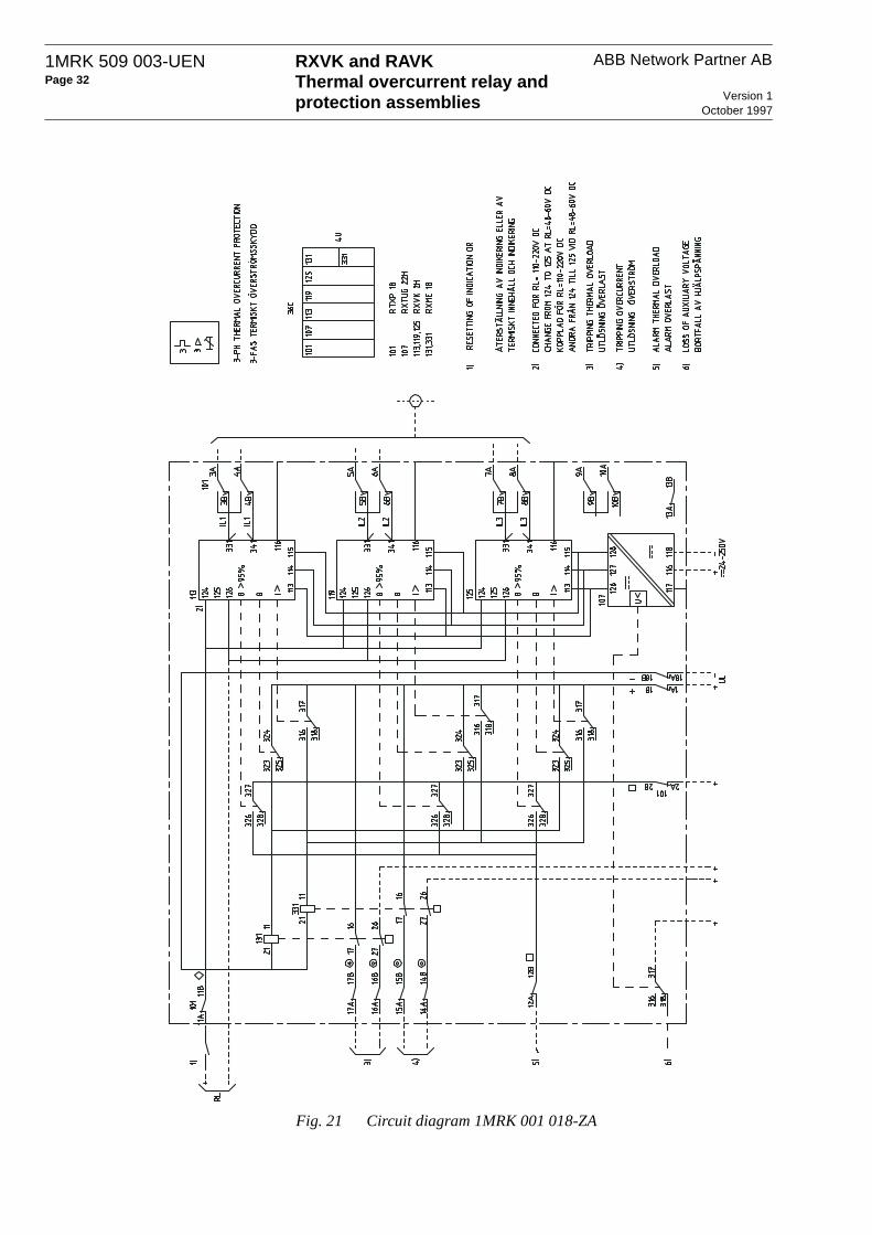
ABB Network Partner ABRXVK and RAVKThermal overcurrent relay and protection assemblies Version 1
October 1997
1MRK 509 003-UENPage 32
Fig. 21 Circuit diagram 1MRK 001 018-ZA

RXVK and RAVKThermal overcurrent relay and protection assemblies
ABB Network Partner AB 1MRK 509 003-UENPage 33
Version 1October 1997
Fig. 22 Terminal diagram 1MRK 001 018-ZAA

ABB Network Partner ABRXVK and RAVKThermal overcurrent relay and protection assemblies Version 1
October 1997
1MRK 509 003-UENPage 34
ABB Network Partner ABS-721 71 VästeråsSwedenTel +46 21 321300Fax +46 21 146918