RX-V750 AV Receiver DSP-AX750SE AV Amplifier - …...YAMAHA HOUSE, 200 RICKMANSWORTH ROAD WATFORD,...
91
RX-V750 AV Receiver DSP-AX750SE AV Amplifier OWNER’S MANUAL MODE D’EMPLOI BEDIENUNGSANLEITUNG BRUKSANVISNING MANUALE DI ISTRUZIONI MANUAL DE INSTRUCCIONES GEBRUIKSAANWIJZING GB
Transcript of RX-V750 AV Receiver DSP-AX750SE AV Amplifier - …...YAMAHA HOUSE, 200 RICKMANSWORTH ROAD WATFORD,...
YAMAHA ELECTRONICS CORPORATION, USA 6660 ORANGETHORPE AVE., BUENA PARK, CALIF. 90620, U.S.A.YAMAHA CANADA MUSIC LTD. 135 MILNER AVE., SCARBOROUGH, ONTARIO M1S 3R1, CANADAYAMAHA ELECTRONIK EUROPA G.m.b.H. SIEMENSSTR. 22-34, 25462 RELLINGEN BEI HAMBURG, F.R. OF GERMANYYAMAHA ELECTRONIQUE FRANCE S.A. RUE AMBROISE CROIZAT BP70 CROISSY-BEAUBOURG 77312 MARNE-LA-VALLEE CEDEX02, FRANCEYAMAHA ELECTRONICS (UK) LTD. YAMAHA HOUSE, 200 RICKMANSWORTH ROAD WATFORD, HERTS WD18 7GQ, ENGLANDYAMAHA SCANDINAVIA A.B. J A WETTERGRENS GATA 1, BOX 30053, 400 43 VÄSTRA FRÖLUNDA, SWEDENYAMAHA MUSIC AUSTRALIA PTY, LTD. 17-33 MARKET ST., SOUTH MELBOURNE, 3205 VIC., AUSTRALIA
© 2004 All rights reserved.
Printed in Malaysia WC85520
RX-V750 AV Receiver
DSP-AX750SE AV Amplifier
OWNER’S MANUALMODE D’EMPLOI
BEDIENUNGSANLEITUNGBRUKSANVISNING
MANUALE DI ISTRUZIONIMANUAL DE INSTRUCCIONES
GEBRUIKSAANWIJZING
GB
RX-V750/DSP-AX750SE
RXV750_RDS_cv.fm Page 1 Wednesday, January 21, 2004 11:44 AM
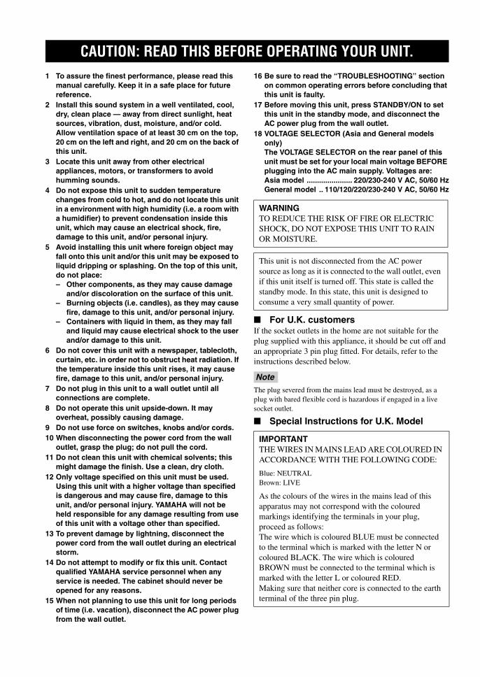
1 To assure the finest performance, please read this manual carefully. Keep it in a safe place for future reference.
2 Install this sound system in a well ventilated, cool, dry, clean place — away from direct sunlight, heat sources, vibration, dust, moisture, and/or cold. Allow ventilation space of at least 30 cm on the top, 20 cm on the left and right, and 20 cm on the back of this unit.
3 Locate this unit away from other electrical appliances, motors, or transformers to avoid humming sounds.
4 Do not expose this unit to sudden temperature changes from cold to hot, and do not locate this unit in a environment with high humidity (i.e. a room with a humidifier) to prevent condensation inside this unit, which may cause an electrical shock, fire, damage to this unit, and/or personal injury.
5 Avoid installing this unit where foreign object may fall onto this unit and/or this unit may be exposed to liquid dripping or splashing. On the top of this unit, do not place:– Other components, as they may cause damage
and/or discoloration on the surface of this unit.– Burning objects (i.e. candles), as they may cause
fire, damage to this unit, and/or personal injury.– Containers with liquid in them, as they may fall
and liquid may cause electrical shock to the user and/or damage to this unit.
6 Do not cover this unit with a newspaper, tablecloth, curtain, etc. in order not to obstruct heat radiation. If the temperature inside this unit rises, it may cause fire, damage to this unit, and/or personal injury.
7 Do not plug in this unit to a wall outlet until all connections are complete.
8 Do not operate this unit upside-down. It may overheat, possibly causing damage.
9 Do not use force on switches, knobs and/or cords.10 When disconnecting the power cord from the wall
outlet, grasp the plug; do not pull the cord.11 Do not clean this unit with chemical solvents; this
might damage the finish. Use a clean, dry cloth.12 Only voltage specified on this unit must be used.
Using this unit with a higher voltage than specified is dangerous and may cause fire, damage to this unit, and/or personal injury. YAMAHA will not be held responsible for any damage resulting from use of this unit with a voltage other than specified.
13 To prevent damage by lightning, disconnect the power cord from the wall outlet during an electrical storm.
14 Do not attempt to modify or fix this unit. Contact qualified YAMAHA service personnel when any service is needed. The cabinet should never be opened for any reasons.
15 When not planning to use this unit for long periods of time (i.e. vacation), disconnect the AC power plug from the wall outlet.
16 Be sure to read the “TROUBLESHOOTING” section on common operating errors before concluding that this unit is faulty.
17 Before moving this unit, press STANDBY/ON to set this unit in the standby mode, and disconnect the AC power plug from the wall outlet.
18 VOLTAGE SELECTOR (Asia and General models only)The VOLTAGE SELECTOR on the rear panel of this unit must be set for your local main voltage BEFORE plugging into the AC main supply. Voltages are:Asia model ...................... 220/230-240 V AC, 50/60 HzGeneral model .. 110/120/220/230-240 V AC, 50/60 Hz
For U.K. customersIf the socket outlets in the home are not suitable for the plug supplied with this appliance, it should be cut off and an appropriate 3 pin plug fitted. For details, refer to the instructions described below.
The plug severed from the mains lead must be destroyed, as a plug with bared flexible cord is hazardous if engaged in a live socket outlet.
Special Instructions for U.K. Model
CAUTION: READ THIS BEFORE OPERATING YOUR UNIT.
WARNINGTO REDUCE THE RISK OF FIRE OR ELECTRIC SHOCK, DO NOT EXPOSE THIS UNIT TO RAIN OR MOISTURE.
This unit is not disconnected from the AC power source as long as it is connected to the wall outlet, even if this unit itself is turned off. This state is called the standby mode. In this state, this unit is designed to consume a very small quantity of power.
Note
IMPORTANTTHE WIRES IN MAINS LEAD ARE COLOURED IN ACCORDANCE WITH THE FOLLOWING CODE:
Blue: NEUTRALBrown: LIVE
As the colours of the wires in the mains lead of this apparatus may not correspond with the coloured markings identifying the terminals in your plug, proceed as follows:The wire which is coloured BLUE must be connected to the terminal which is marked with the letter N or coloured BLACK. The wire which is coloured BROWN must be connected to the terminal which is marked with the letter L or coloured RED.Making sure that neither core is connected to the earth terminal of the three pin plug.
01EN_00_RXV750_GB.book Page i Thursday, February 12, 2004 5:15 PM
1
En
glish
PR
EPA
RA
TIO
NIN
TR
OD
UC
TIO
NB
AS
IC
OP
ER
AT
ION
SO
UN
D F
IEL
D
PR
OG
RA
MS
AD
VAN
CE
D
OP
ER
AT
ION
AD
DIT
ION
AL
IN
FO
RM
AT
ION
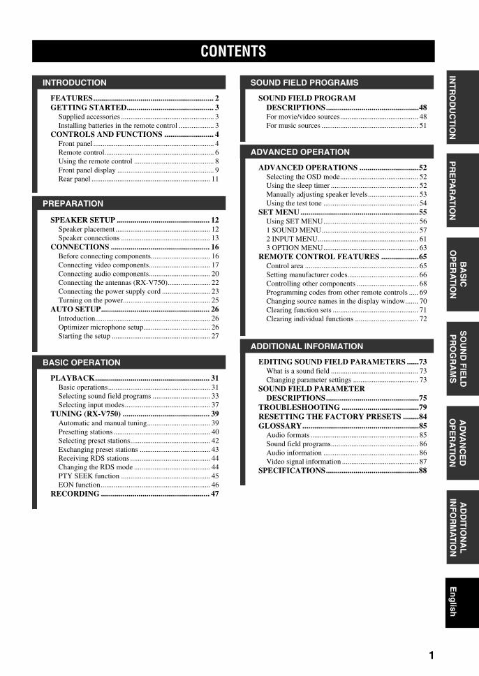
FEATURES............................................................. 2GETTING STARTED............................................ 3
Supplied accessories .................................................. 3Installing batteries in the remote control ................... 3
CONTROLS AND FUNCTIONS ......................... 4Front panel ................................................................. 4Remote control........................................................... 6Using the remote control ........................................... 8Front panel display .................................................... 9Rear panel ................................................................ 11
SPEAKER SETUP ............................................... 12Speaker placement ................................................... 12Speaker connections ................................................ 13
CONNECTIONS .................................................. 16Before connecting components................................ 16Connecting video components................................. 17Connecting audio components................................. 20Connecting the antennas (RX-V750)....................... 22Connecting the power supply cord .......................... 23Turning on the power............................................... 25
AUTO SETUP....................................................... 26Introduction.............................................................. 26Optimizer microphone setup.................................... 26Starting the setup ..................................................... 27
PLAYBACK.......................................................... 31Basic operations....................................................... 31Selecting sound field programs ............................... 33Selecting input modes.............................................. 37
TUNING (RX-V750) ............................................ 39Automatic and manual tuning.................................. 39Presetting stations .................................................... 40Selecting preset stations........................................... 42Exchanging preset stations ...................................... 43Receiving RDS stations ........................................... 44Changing the RDS mode ......................................... 44PTY SEEK function ................................................ 45EON function........................................................... 46
RECORDING ....................................................... 47
SOUND FIELD PROGRAM DESCRIPTIONS...............................................48For movie/video sources.......................................... 48For music sources .................................................... 51
ADVANCED OPERATIONS ..............................52Selecting the OSD mode.......................................... 52Using the sleep timer ............................................... 52Manually adjusting speaker levels........................... 53Using the test tone ................................................... 54
SET MENU ............................................................55Using SET MENU................................................... 561 SOUND MENU.................................................... 572 INPUT MENU...................................................... 613 OPTION MENU................................................... 63
REMOTE CONTROL FEATURES ...................65Control area ............................................................. 65Setting manufacturer codes...................................... 66Controlling other components ................................. 68Programming codes from other remote controls ..... 69Changing source names in the display window....... 70Clearing function sets .............................................. 71Clearing individual functions .................................. 72
EDITING SOUND FIELD PARAMETERS ......73What is a sound field ............................................... 73Changing parameter settings ................................... 73
SOUND FIELD PARAMETER DESCRIPTIONS...............................................75
TROUBLESHOOTING .......................................79RESETTING THE FACTORY PRESETS ........84GLOSSARY...........................................................85
Audio formats .......................................................... 85Sound field programs............................................... 86Audio information ................................................... 86Video signal information ......................................... 87
SPECIFICATIONS...............................................88
CONTENTS
INTRODUCTION
PREPARATION
BASIC OPERATION
SOUND FIELD PROGRAMS
ADVANCED OPERATION
ADDITIONAL INFORMATION
01EN_00_RXV750_GB.book Page 1 Thursday, February 12, 2004 5:15 PM

FEATURES
2
Built-in 7-channel power amplifier Minimum RMS output power
(0.06% THD, 20 Hz – 20 kHz, 8Ω)Front: 100 W + 100 WCenter: 100 WSurround: 100 W + 100 WSurround back: 100 W + 100 W
Sound field features Proprietary YAMAHA technology for the creation of
sound fields Dolby Digital/Dolby Digital EX decoder DTS/DTS-ES Matrix 6.1, Discrete 6.1, DTS Neo:6,
DTS 96/24 decoder Dolby Pro Logic/Dolby Pro Logic II/Dolby Pro Logic
IIx decoder Virtual CINEMA DSP SILENT CINEMA™
Sophisticated AM/FM tuner (RX-V750) 40-station random access preset tuning Automatic preset tuning Preset station shifting capability (preset editing)
Other features YPAO: YAMAHA Parametric Room Acoustic
Optimizer for automatic speaker setup 192-kHz/24-bit D/A converter A SET MENU which provides you with items for
optimizing this unit for your audio/video system 8 additional input jacks for discrete multi-channel input PURE DIRECT for pure fidelity sound with analog and
PCM sources On-screen display function helpful in controlling this
unit S-Video signal input/output capability Component video input/output capability Video signal conversion (Composite video ↔ S-Video
→ Component video) capability for monitor out Optical and coaxial digital audio signal jacks Sleep timer Cinema and music night listening modes Remote control with preset manufacturer codes and
“learning” capability
• This document is the owner’s manual for both RX-V750 and DSP-AX750SE. Since DSP-AX750SE does not incorporate a tuner, descriptions on tuning are not applicable for DSP-AX750SE. Illustrations for the RX-V750 are mainly used for explanations.
• y indicates a tip for your operation.• Some operations can be performed by using either the buttons on the main unit or on the remote control. In cases when the button
names differ between the main unit and the remote control, the button name on the remote control is given in parentheses.• This manual is printed prior to production. Design and specifications are subject to change in part as a result of improvements, etc. In
case of differences between the manual and product, the product has priority.
Manufactured under license from Dolby Laboratories.“Dolby”, “Pro Logic”, “Surround EX”, and the double-D symbol are trademarks of Dolby Laboratories.
“SILENT CINEMA” is a trademark of YAMAHA CORPORATION.
“DTS”, “DTS-ES”, “Neo:6” and “DTS 96/24” are trademarks of Digital Theater Systems, Inc.
FEATURES
01EN_00_RXV750_GB.book Page 2 Thursday, February 12, 2004 5:15 PM
GETTING STARTED
3
En
glish
INT
RO
DU
CT
ION
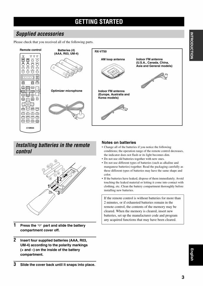
Please check that you received all of the following parts.
1 Press the part and slide the battery compartment cover off.
2 Insert four supplied batteries (AAA, R03, UM-4) according to the polarity markings (+ and –) on the inside of the battery compartment.
3 Slide the cover back until it snaps into place.
Notes on batteries• Change all of the batteries if you notice the following
conditions; the operation range of the remote control decreases, the indicator does not flash or its light becomes dim.
• Do not use old batteries together with new ones.• Do not use different types of batteries (such as alkaline and
manganese batteries) together. Read the packaging carefully as these different types of batteries may have the same shape and color.
• If the batteries have leaked, dispose of them immediately. Avoid touching the leaked material or letting it come into contact with clothing, etc. Clean the battery compartment thoroughly before installing new batteries.
GETTING STARTED
Supplied accessories
TRANSMIT RE-NAME
INPUT MODESTANDBYSYSTEMPOWER
A B PHONO
CDMD/CD-RTUNERV-AUX
DVD
AMPPOWERPOWER
REC
AUDIO
MUTE
MENUTITLE
CH CH
VOL
DISC SKIP
FREQ/RDS EON
STARTSET MENULEVEL
A/B/C/D/ETV INPUT
MODE PTY SEEK
TV VOL
PRESET
TEST ON SCREEN STRAIGHT
ROCKJAZZHALLSTEREO
4321
8
10
7
09
65
ENTER
MOVIETV THTRMUSIC ENTERTAIN
EX/ESNIGHTq/DTS PURE DIRECT
EFFECT
CHP/INDEX
DISPLAYRETURN
PRESET
TV MUTESELECT
TV VOL
AVTV
SELECT
VCR 1DTV/CBL DVR/VCR2
MULTI CH IN
SLEEP
CLEAR LEARN
Remote control Batteries (4) (AAA, R03, UM-4)
Indoor FM antenna(U.S.A., Canada, China, Asia and General models)
AM loop antenna
Indoor FM antenna(Europe, Australia and Korea models)
Optimizer microphone
RX-V750
Installing batteries in the remote control
13
2
If the remote control is without batteries for more than 2 minutes, or if exhausted batteries remain in the remote control, the contents of the memory may be cleared. When the memory is cleared, insert new batteries, set up the manufacturer code and program any acquired functions that may have been cleared.
01EN_00_RXV750_GB.book Page 3 Thursday, February 12, 2004 5:15 PM
CONTROLS AND FUNCTIONS
4
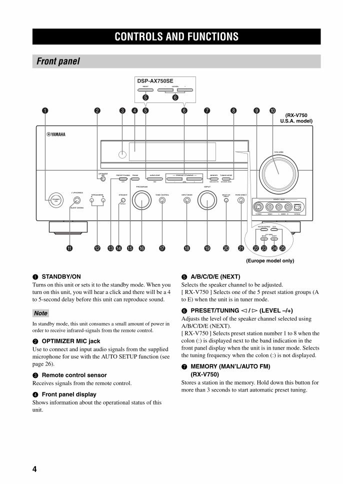
1 STANDBY/ONTurns on this unit or sets it to the standby mode. When you turn on this unit, you will hear a click and there will be a 4 to 5-second delay before this unit can reproduce sound.
In standby mode, this unit consumes a small amount of power in order to receive infrared-signals from the remote control.
2 OPTIMIZER MIC jackUse to connect and input audio signals from the supplied microphone for use with the AUTO SETUP function (see page 26).
3 Remote control sensorReceives signals from the remote control.
4 Front panel displayShows information about the operational status of this unit.
5 A/B/C/D/E (NEXT)Selects the speaker channel to be adjusted.[ RX-V750 ] Selects one of the 5 preset station groups (A to E) when the unit is in tuner mode.
6 PRESET/TUNING l / h (LEVEL –/+)Adjusts the level of the speaker channel selected using A/B/C/D/E (NEXT).[ RX-V750 ] Selects preset station number 1 to 8 when the colon (:) is displayed next to the band indication in the front panel display when the unit is in tuner mode. Selects the tuning frequency when the colon (:) is not displayed.
7 MEMORY (MAN’L/AUTO FM)(RX-V750)
Stores a station in the memory. Hold down this button for more than 3 seconds to start automatic preset tuning.
CONTROLS AND FUNCTIONS
Front panel
AUTO/MAN'L MONO
S VIDEO VIDEO OPTICALL AUDIO R
MAN'L/AUTO FMLEVELNEXTEDIT
EFFECT
MEMORYFM/AMPRESET/TUNINGOPTIMIZER
MIC A/B/C/D/E
PROGRAM
l PRESET/TUNING h TUNING MODE
PURE DIRECTINPUT MODETONE CONTROLSTRAIGHTSPEAKERSPHONES
SILENT CINEMA
STANDBY/ON
BAMULTI CH
INPUT
VOLUME
VIDEO AUX
INPUT
NEXT
DSP-AX750SELEVEL
31 4 52 6 09
J KHGEBA CD F I
RDS MODE/FREQ EON
MODEPTY SEEK
START
M NOL
7 8
5 6
(RX-V750 U.S.A. model)
(Europe model only)
Note
01EN_00_RXV750_GB.book Page 4 Thursday, February 12, 2004 5:15 PM
CONTROLS AND FUNCTIONS
5
En
glish
INT
RO
DU
CT
ION
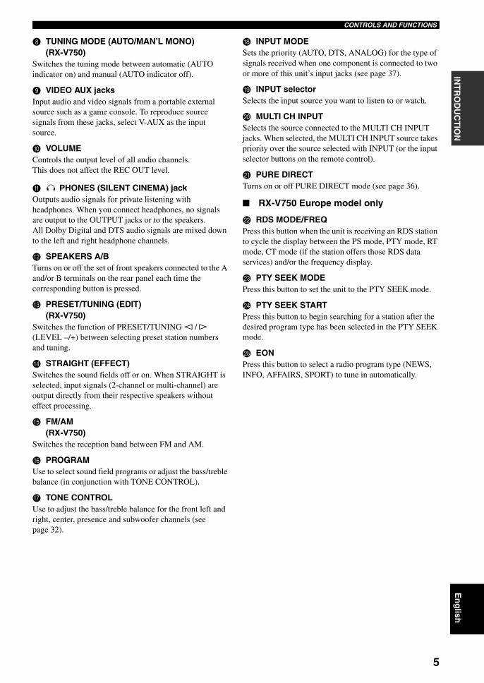
8 TUNING MODE (AUTO/MAN’L MONO)(RX-V750)
Switches the tuning mode between automatic (AUTO indicator on) and manual (AUTO indicator off).
9 VIDEO AUX jacksInput audio and video signals from a portable external source such as a game console. To reproduce source signals from these jacks, select V-AUX as the input source.
0 VOLUMEControls the output level of all audio channels.This does not affect the REC OUT level.
A PHONES (SILENT CINEMA) jackOutputs audio signals for private listening with headphones. When you connect headphones, no signals are output to the OUTPUT jacks or to the speakers.All Dolby Digital and DTS audio signals are mixed down to the left and right headphone channels.
B SPEAKERS A/BTurns on or off the set of front speakers connected to the A and/or B terminals on the rear panel each time the corresponding button is pressed.
C PRESET/TUNING (EDIT)(RX-V750)
Switches the function of PRESET/TUNING l / h (LEVEL –/+) between selecting preset station numbers and tuning.
D STRAIGHT (EFFECT)Switches the sound fields off or on. When STRAIGHT is selected, input signals (2-channel or multi-channel) are output directly from their respective speakers without effect processing.
E FM/AM(RX-V750)
Switches the reception band between FM and AM.
F PROGRAMUse to select sound field programs or adjust the bass/treble balance (in conjunction with TONE CONTROL).
G TONE CONTROLUse to adjust the bass/treble balance for the front left and right, center, presence and subwoofer channels (see page 32).
H INPUT MODESets the priority (AUTO, DTS, ANALOG) for the type of signals received when one component is connected to two or more of this unit’s input jacks (see page 37).
I INPUT selectorSelects the input source you want to listen to or watch.
J MULTI CH INPUTSelects the source connected to the MULTI CH INPUT jacks. When selected, the MULTI CH INPUT source takes priority over the source selected with INPUT (or the input selector buttons on the remote control).
K PURE DIRECTTurns on or off PURE DIRECT mode (see page 36).
RX-V750 Europe model only
L RDS MODE/FREQPress this button when the unit is receiving an RDS station to cycle the display between the PS mode, PTY mode, RT mode, CT mode (if the station offers those RDS data services) and/or the frequency display.
M PTY SEEK MODEPress this button to set the unit to the PTY SEEK mode.
N PTY SEEK STARTPress this button to begin searching for a station after the desired program type has been selected in the PTY SEEK mode.
O EONPress this button to select a radio program type (NEWS, INFO, AFFAIRS, SPORT) to tune in automatically.
01EN_00_RXV750_GB.book Page 5 Thursday, February 12, 2004 5:15 PM
CONTROLS AND FUNCTIONS
6
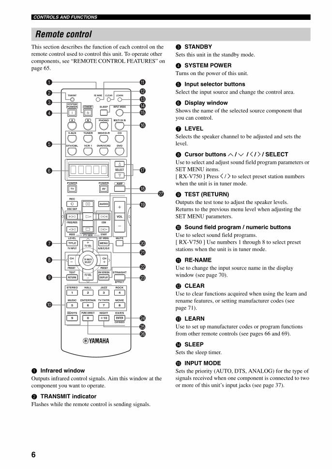
This section describes the function of each control on the remote control used to control this unit. To operate other components, see “REMOTE CONTROL FEATURES” on page 65.
1 Infrared windowOutputs infrared control signals. Aim this window at the component you want to operate.
2 TRANSMIT indicatorFlashes while the remote control is sending signals.
3 STANDBYSets this unit in the standby mode.
4 SYSTEM POWERTurns on the power of this unit.
5 Input selector buttonsSelect the input source and change the control area.
6 Display windowShows the name of the selected source component that you can control.
7 LEVELSelects the speaker channel to be adjusted and sets the level.
8 Cursor buttons u / d / j / i / SELECTUse to select and adjust sound field program parameters or SET MENU items.[ RX-V750 ] Press j / i to select preset station numbers when the unit is in tuner mode.
9 TEST (RETURN)Outputs the test tone to adjust the speaker levels.Returns to the previous menu level when adjusting the SET MENU parameters.
0 Sound field program / numeric buttonsUse to select sound field programs.[ RX-V750 ] Use numbers 1 through 8 to select preset stations when the unit is in tuner mode.
A RE-NAMEUse to change the input source name in the display window (see page 70).
B CLEARUse to clear functions acquired when using the learn and rename features, or setting manufacturer codes (see page 71).
C LEARNUse to set up manufacturer codes or program functions from other remote controls (see pages 66 and 69).
D SLEEPSets the sleep timer.
E INPUT MODESets the priority (AUTO, DTS, ANALOG) for the type of signals received when one component is connected to two or more of this unit’s input jacks (see page 37).
Remote control
TRANSMIT RE-NAME
INPUT MODESTANDBYSYSTEMPOWER
A B PHONO
CDMD/CD-RTUNERV-AUX
DVD
AMPPOWERPOWER
REC
AUDIO
MUTE
MENUTITLE
CH CH
VOL
DISC SKIP
FREQ/RDS EON
STARTSET MENULEVEL
A/B/C/D/ETV INPUT
MODE PTY SEEK
TV VOL
PRESET
TEST ON SCREEN STRAIGHT
ROCKJAZZHALLSTEREO
4321
8
10
7
09
65
ENTER
MOVIETV THTRMUSIC ENTERTAIN
EX/ESNIGHTq/DTS PURE DIRECT
EFFECT
CHP/INDEX
DISPLAYRETURN
PRESET
TV MUTESELECT
TV VOL
AVTV
SELECT
VCR 1DTV/CBL DVR/VCR2
MULTI CH IN
SLEEP
CLEAR LEARN
A
BCDE
G
I
J
K
L
M
N
P
HQ
8
9
7
0
2
3
4
1
6
5
F
O
01EN_00_RXV750_GB.book Page 6 Thursday, February 12, 2004 5:15 PM
CONTROLS AND FUNCTIONS
7
En
glish
INT
RO
DU
CT
ION
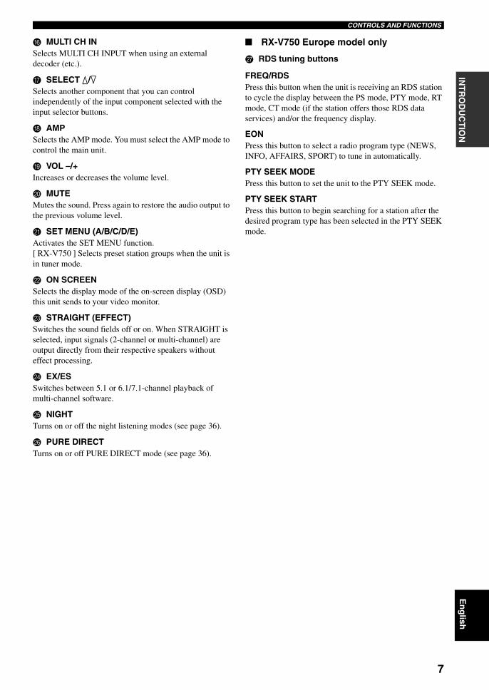
F MULTI CH INSelects MULTI CH INPUT when using an external decoder (etc.).
G SELECT k/nSelects another component that you can control independently of the input component selected with the input selector buttons.
H AMPSelects the AMP mode. You must select the AMP mode to control the main unit.
I VOL –/+Increases or decreases the volume level.
J MUTEMutes the sound. Press again to restore the audio output to the previous volume level.
K SET MENU (A/B/C/D/E)Activates the SET MENU function.[ RX-V750 ] Selects preset station groups when the unit is in tuner mode.
L ON SCREENSelects the display mode of the on-screen display (OSD) this unit sends to your video monitor.
M STRAIGHT (EFFECT)Switches the sound fields off or on. When STRAIGHT is selected, input signals (2-channel or multi-channel) are output directly from their respective speakers without effect processing.
N EX/ESSwitches between 5.1 or 6.1/7.1-channel playback of multi-channel software.
O NIGHTTurns on or off the night listening modes (see page 36).
P PURE DIRECTTurns on or off PURE DIRECT mode (see page 36).
RX-V750 Europe model only
Q RDS tuning buttons
FREQ/RDSPress this button when the unit is receiving an RDS station to cycle the display between the PS mode, PTY mode, RT mode, CT mode (if the station offers those RDS data services) and/or the frequency display.
EONPress this button to select a radio program type (NEWS, INFO, AFFAIRS, SPORT) to tune in automatically.
PTY SEEK MODEPress this button to set the unit to the PTY SEEK mode.
PTY SEEK STARTPress this button to begin searching for a station after the desired program type has been selected in the PTY SEEK mode.
01EN_00_RXV750_GB.book Page 7 Thursday, February 12, 2004 5:15 PM
CONTROLS AND FUNCTIONS
8
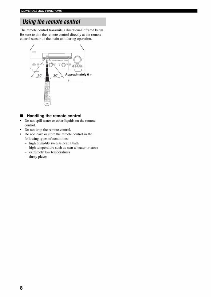
The remote control transmits a directional infrared beam.Be sure to aim the remote control directly at the remote control sensor on the main unit during operation.
Handling the remote control• Do not spill water or other liquids on the remote
control.• Do not drop the remote control.• Do not leave or store the remote control in the
following types of conditions:– high humidity such as near a bath– high temperature such as near a heater or stove– extremely low temperatures– dusty places
Using the remote control
AUTO/MAN'L MONO
S VIDEO VIDEO OPTICALL AUDIO R
MAN'L/AUTO FMLEVELNEXTEDIT
EFFECT
MEMORYFM/AMPRESET/TUNINGOPTIMIZER
MIC A/B/C/D/E
PROGRAM
l PRESET/TUNING h TUNING MODE
PURE DIRECTINPUT MODETONE CONTROLSTRAIGHTSPEAKERSPHONES
SILENT CINEMA
STANDBY/ON
BAMULTI CH
INPUT
VOLUME
VIDEO AUX
INPUT
30 30
TRANSMIT RE–NAME CLEAR LEARN
POWER SLEEPSTANDBY INPUT MODESYSTEM
PHONO TUNER CD MULTI CH IN
V-AUX CBL/SAT MD/TAPE CD-R
DTV DVR/VCR2VCR 1 DVD
SELECT
POWER
TV
POWER
AV
AMP
REC
DISC SKIP
AUDIO
VOL
LEVEL
TITLE
TV INPUTTV VOL
SET MENU
MENU
A/B/C/D/E
MUTE
CH TV MUTESELECT
CH
PRESET PRESET
TEST
RETURNTV VOL
ON SCREEN
DISPLAY
STRAIGHT
EFFECT
STEREO HALL JAZZ ROCK
1 2 3 4
5 6 8
ENTERTAIN MUSIC TV THTR MOVIE
7
9 0 ENTER+10
EX/ESTHX /DTS NIGHT
CHP/INDEX
Approximately 6 m
01EN_00_RXV750_GB.book Page 8 Thursday, February 12, 2004 5:15 PM
CONTROLS AND FUNCTIONS
9
En
glish
INT
RO
DU
CT
ION
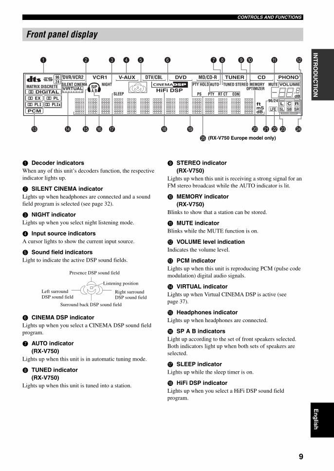
1 Decoder indicatorsWhen any of this unit’s decoders function, the respective indicator lights up.
2 SILENT CINEMA indicatorLights up when headphones are connected and a sound field program is selected (see page 32).
3 NIGHT indicatorLights up when you select night listening mode.
4 Input source indicatorsA cursor lights to show the current input source.
5 Sound field indicatorsLight to indicate the active DSP sound fields.
6 CINEMA DSP indicatorLights up when you select a CINEMA DSP sound field program.
7 AUTO indicator(RX-V750)
Lights up when this unit is in automatic tuning mode.
8 TUNED indicator(RX-V750)
Lights up when this unit is tuned into a station.
9 STEREO indicator(RX-V750)
Lights up when this unit is receiving a strong signal for an FM stereo broadcast while the AUTO indicator is lit.
0 MEMORY indicator(RX-V750)
Blinks to show that a station can be stored.
A MUTE indicatorBlinks while the MUTE function is on.
B VOLUME level indicationIndicates the volume level.
C PCM indicatorLights up when this unit is reproducing PCM (pulse code modulation) digital audio signals.
D VIRTUAL indicatorLights up when Virtual CINEMA DSP is active (see page 37).
E Headphones indicatorLights up when headphones are connected.
F SP A B indicatorsLight up according to the set of front speakers selected. Both indicators light up when both sets of speakers are selected.
G SLEEP indicatorLights up while the sleep timer is on.
H HiFi DSP indicatorLights up when you select a HiFi DSP sound field program.
Front panel display
PHONOCDTUNERMD/CD-RDVD
HiFi DSP
DTV/CBLV-AUXVCR1DVR/VCR29624
q PLq EXq PL
MATRIX DISCRETE SILENT CINEMA NIGHT PTY HOLD AUTO
PS RT CT EONPTY
TUNED STEREO MUTE VOLUMEMEMORY
SLEEPVIRTUAL
PCMq PL x
A BSP
ftmSdB
dB96/24
LFEL C RSL SB SR
q DIGITAL
t
OPTIMIZER
1 2 3 4 5 6 7 8 0 A B9
F G
O
H I LJ MK NEDC
(RX-V750 Europe model only)
Presence DSP sound field
Listening position
Left surroundDSP sound field
Right surroundDSP sound field
Surround back DSP sound field
01EN_00_RXV750_GB.book Page 9 Thursday, February 12, 2004 5:15 PM
CONTROLS AND FUNCTIONS
10
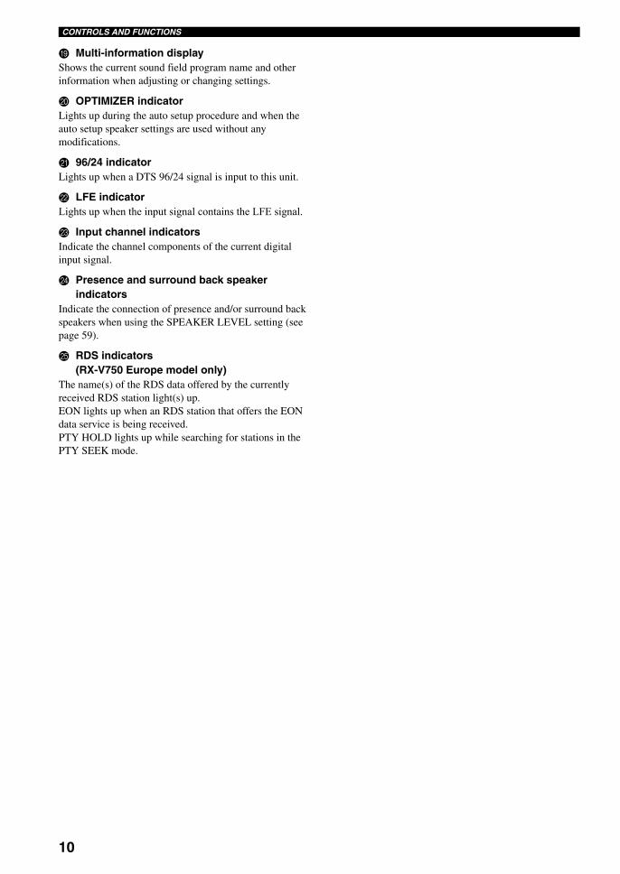
I Multi-information displayShows the current sound field program name and other information when adjusting or changing settings.
J OPTIMIZER indicatorLights up during the auto setup procedure and when the auto setup speaker settings are used without any modifications.
K 96/24 indicatorLights up when a DTS 96/24 signal is input to this unit.
L LFE indicatorLights up when the input signal contains the LFE signal.
M Input channel indicatorsIndicate the channel components of the current digital input signal.
N Presence and surround back speaker indicators
Indicate the connection of presence and/or surround back speakers when using the SPEAKER LEVEL setting (see page 59).
O RDS indicators(RX-V750 Europe model only)
The name(s) of the RDS data offered by the currently received RDS station light(s) up.EON lights up when an RDS station that offers the EON data service is being received.PTY HOLD lights up while searching for stations in the PTY SEEK mode.
01EN_00_RXV750_GB.book Page 10 Thursday, February 12, 2004 5:15 PM
CONTROLS AND FUNCTIONS
11
En
glish
INT
RO
DU
CT
ION
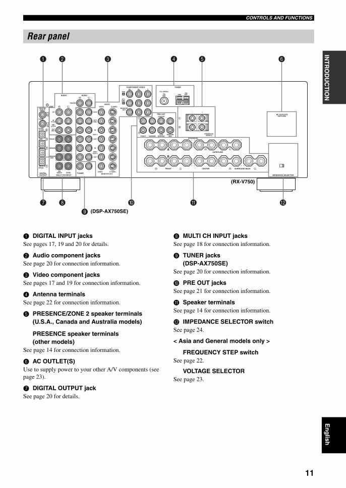
1 DIGITAL INPUT jacksSee pages 17, 19 and 20 for details.
2 Audio component jacksSee page 20 for connection information.
3 Video component jacksSee pages 17 and 19 for connection information.
4 Antenna terminalsSee page 22 for connection information.
5 PRESENCE/ZONE 2 speaker terminals(U.S.A., Canada and Australia models)
PRESENCE speaker terminals(other models)
See page 14 for connection information.
6 AC OUTLET(S)Use to supply power to your other A/V components (see page 23).
7 DIGITAL OUTPUT jackSee page 20 for details.
8 MULTI CH INPUT jacks See page 18 for connection information.
9 TUNER jacks(DSP-AX750SE)
See page 20 for connection information.
0 PRE OUT jacksSee page 21 for connection information.
A Speaker terminalsSee page 14 for connection information.
B IMPEDANCE SELECTOR switchSee page 24.
< Asia and General models only >
FREQUENCY STEP switchSee page 22.
VOLTAGE SELECTORSee page 23.
Rear panel
GND
AUDIO AUDIO
DIGITALINPUT
DVD
DVD
CD
COAXIAL
OPTICAL DTV/CBL
MD/CD-R
MD/CD-ROPTICAL
SUBWOOFER
SURROUNDBACK
SURROUND
FRONT
OUT(REC)
IN(PLAY)
MD/CD-R
CD
PHONO
DVD
VIDEO
VIDEOS VIDEO
MONITOROUT
DTV/CBL
DVD
COMPONENT VIDEOPR PB Y
75Ω UNBAL.
FMANT
AMANTGND
TUNER
DTV/CBL
IN
VCR 1
OUT
IN
DVR/VCR 2
OUT
CENTERDIGITALOUTPUT MULTI CH INPUT
TUNERVIDEO S VIDEO
MONITOR OUT
FRONTSUB
WOOFER
FRONT
A
B
CENTER
PRE OUT
SURROUNDSURROUND
BACKPRESENCE
/ZONE 2
SPEAKERS
SURROUND
CENTER SURROUND BACK
IMPEDANCE SELECTOR
AC OUTLETSSWITCHED
1 2 3 4 5
7 8
9
0 A B
6
(RX-V750)
(DSP-AX750SE)
01EN_00_RXV750_GB.book Page 11 Thursday, February 12, 2004 5:15 PM
SPEAKER SETUP
12
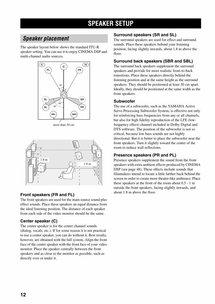
The speaker layout below shows the standard ITU-R speaker setting. You can use it to enjoy CINEMA DSP and multi-channel audio sources.
Front speakers (FR and FL)The front speakers are used for the main source sound plus effect sounds. Place these speakers an equal distance from the ideal listening position. The distance of each speaker from each side of the video monitor should be the same.
Center speaker (C)The center speaker is for the center channel sounds (dialog, vocals, etc.). If for some reason it is not practical to use a center speaker, you can do without it. Best results, however, are obtained with the full system. Align the front face of the center speaker with the front face of your video monitor. Place the speaker centrally between the front speakers and as close to the monitor as possible, such as directly over or under it.
Surround speakers (SR and SL)The surround speakers are used for effect and surround sounds. Place these speakers behind your listening position, facing slightly inwards, about 1.8 m above the floor.
Surround back speakers (SBR and SBL)The surround back speakers supplement the surround speakers and provide for more realistic front-to-back transitions. Place these speakers directly behind the listening position and at the same height as the surround speakers. They should be positioned at least 30 cm apart. Ideally, they should be positioned at the same width as the front speakers.
SubwooferThe use of a subwoofer, such as the YAMAHA Active Servo Processing Subwoofer System, is effective not only for reinforcing bass frequencies from any or all channels, but also for high fidelity reproduction of the LFE (low-frequency effect) channel included in Dolby Digital and DTS software. The position of the subwoofer is not so critical, because low bass sounds are not highly directional. But it is better to place the subwoofer near the front speakers. Turn it slightly toward the center of the room to reduce wall reflections.
Presence speakers (PR and PL)Presence speakers supplement the sound from the front speakers with extra ambient effects produced by CINEMA DSP (see page 48). These effects include sounds that filmmakers intend to locate a little farther back behind the screen in order to create more theater-like ambience. Place these speakers at the front of the room about 0.5 - 1 m outside the front speakers, facing slightly inwards, and about 1.8 m above the floor.
SPEAKER SETUP
Speaker placement
60˚
30˚
PL PR
SBRSBL
FL FRC
SL
SR
SR80˚
SL
more than 30 cm
1.8 m1.8 m
01EN_00_RXV750_GB.book Page 12 Thursday, February 12, 2004 5:15 PM
13
En
glish
SPEAKER SETUPP
RE
PAR
AT
ION
Be sure to connect the left channel (L), right channel (R), “+” (red) and “–” (black) properly. If the connections are faulty, no sound will be heard from the speakers, and if the polarity of the speaker connections is incorrect, the sound will be unnatural and lack bass.
• If you will use 6 ohm speakers, be sure to set this unit’s speaker impedance setting to 6 ohms before using (see page 24).
• Before connecting the speakers, make sure that the power of this unit is off.
• Do not let the bare speaker wires touch each other or do not let them touch any metal part of this unit. This could damage this unit and/or speakers.
• Use magnetically shielded speakers. If this type of speakers still creates the interference with the monitor, place the speakers away from the monitor.
A speaker cord is actually a pair of insulated cables running side by side. One cable is colored or shaped differently, perhaps with a stripe, groove or ridges. Connect the striped (grooved, etc.) cable to the “+” (red) terminals on this unit and your speaker. Connect the plain cable to the “–” (black) terminals.
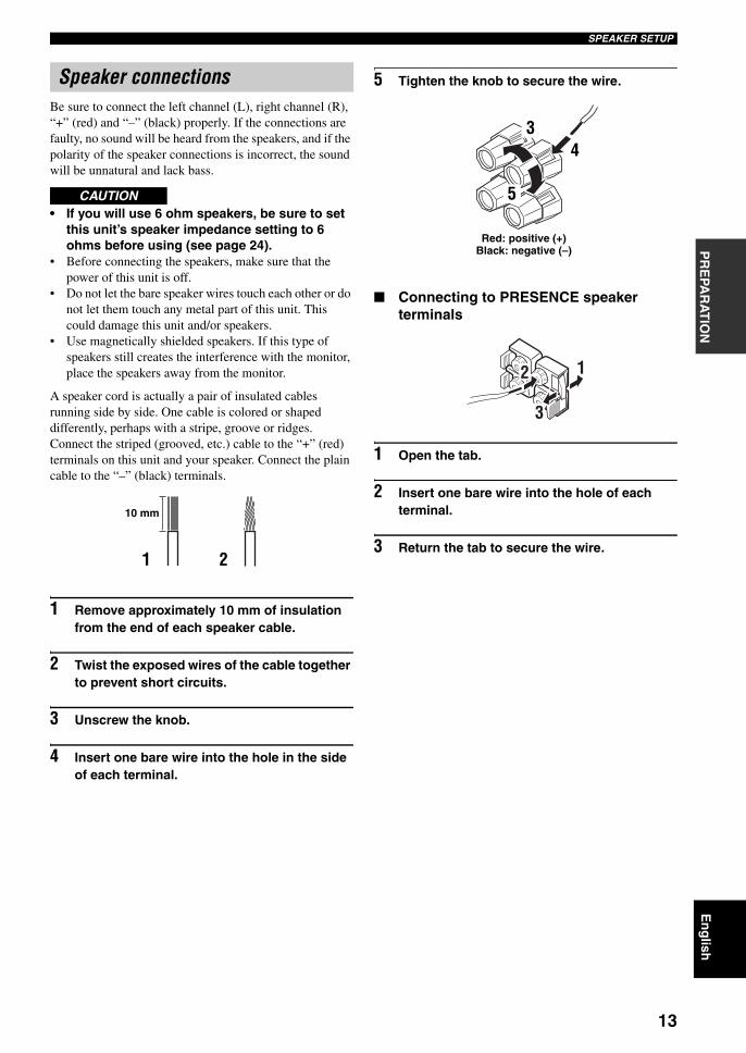
1 Remove approximately 10 mm of insulation from the end of each speaker cable.
2 Twist the exposed wires of the cable together to prevent short circuits.
3 Unscrew the knob.
4 Insert one bare wire into the hole in the side of each terminal.
5 Tighten the knob to secure the wire.
Connecting to PRESENCE speaker terminals
1 Open the tab.
2 Insert one bare wire into the hole of each terminal.
3 Return the tab to secure the wire.
Speaker connections
CAUTION
10 mm
1 2
Red: positive (+)Black: negative (–)
34
5
2 1
3
01EN_00_RXV750_GB.book Page 13 Thursday, February 12, 2004 5:15 PM
14
SPEAKER SETUP
FRONTSUB
WOOFER
FRONT
A
B
CENTER
PRE OUT
SURROUNDSURROUND
BACKPRESENCE
/ZONE 2
SPEAKERS
SURROUND
CENTER SURROUND BACK
2 31
6 7 1098
4 5
Subwoofer system
Center speaker
Front speakers (A)
Surround back speakers
LeftRight
LeftRightSurround speakers
Front speakers
(B)
(RX-V750)
LeftRight
LeftRightPresence speakers
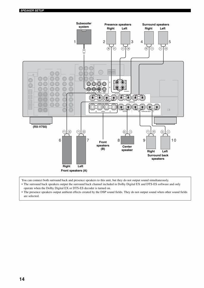
You can connect both surround back and presence speakers to this unit, but they do not output sound simultaneously.• The surround back speakers output the surround back channel included in Dolby Digital EX and DTS-ES software and only
operate when the Dolby Digital EX or DTS-ES decoder is turned on.• The presence speakers output ambient effects created by the DSP sound fields. They do not output sound when other sound fields
are selected.
01EN_00_RXV750_GB.book Page 14 Thursday, February 12, 2004 5:15 PM
15
En
glish
SPEAKER SETUPP
RE
PAR
AT
ION
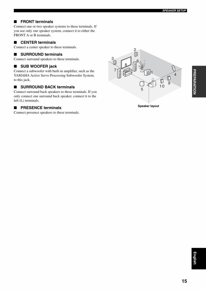
FRONT terminalsConnect one or two speaker systems to these terminals. If you use only one speaker system, connect it to either the FRONT A or B terminals.
CENTER terminalsConnect a center speaker to these terminals.
SURROUND terminalsConnect surround speakers to these terminals.
SUB WOOFER jackConnect a subwoofer with built-in amplifier, such as the YAMAHA Active Servo Processing Subwoofer System, to this jack.
SURROUND BACK terminalsConnect surround back speakers to these terminals. If you only connect one surround back speaker, connect it to the left (L) terminals.
PRESENCE terminalsConnect presence speakers to these terminals.
1
6
78
9
2
3
5
4
10
Speaker layout
01EN_00_RXV750_GB.book Page 15 Thursday, February 12, 2004 5:15 PM
CONNECTIONS
16
Do not connect this unit or other components to the mains power until all connections between components are complete.
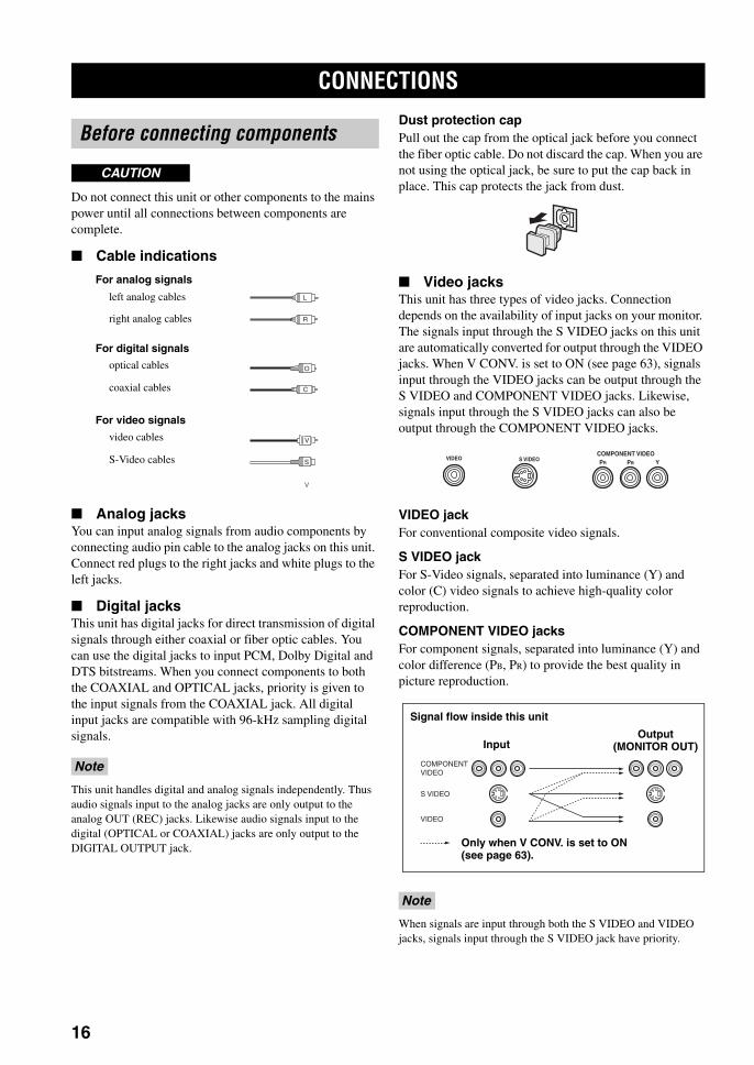
Cable indications
Analog jacksYou can input analog signals from audio components by connecting audio pin cable to the analog jacks on this unit. Connect red plugs to the right jacks and white plugs to the left jacks.
Digital jacksThis unit has digital jacks for direct transmission of digital signals through either coaxial or fiber optic cables. You can use the digital jacks to input PCM, Dolby Digital and DTS bitstreams. When you connect components to both the COAXIAL and OPTICAL jacks, priority is given to the input signals from the COAXIAL jack. All digital input jacks are compatible with 96-kHz sampling digital signals.
This unit handles digital and analog signals independently. Thus audio signals input to the analog jacks are only output to the analog OUT (REC) jacks. Likewise audio signals input to the digital (OPTICAL or COAXIAL) jacks are only output to the DIGITAL OUTPUT jack.
Dust protection capPull out the cap from the optical jack before you connect the fiber optic cable. Do not discard the cap. When you are not using the optical jack, be sure to put the cap back in place. This cap protects the jack from dust.
Video jacksThis unit has three types of video jacks. Connection depends on the availability of input jacks on your monitor. The signals input through the S VIDEO jacks on this unit are automatically converted for output through the VIDEO jacks. When V CONV. is set to ON (see page 63), signals input through the VIDEO jacks can be output through the S VIDEO and COMPONENT VIDEO jacks. Likewise, signals input through the S VIDEO jacks can also be output through the COMPONENT VIDEO jacks.
VIDEO jackFor conventional composite video signals.
S VIDEO jackFor S-Video signals, separated into luminance (Y) and color (C) video signals to achieve high-quality color reproduction.
COMPONENT VIDEO jacksFor component signals, separated into luminance (Y) and color difference (PB, PR) to provide the best quality in picture reproduction.
When signals are input through both the S VIDEO and VIDEO jacks, signals input through the S VIDEO jack have priority.
CONNECTIONS
Before connecting components
Note
CAUTION
S
V
O
V
V
V
L
R
C
left analog cables
right analog cables
optical cables
coaxial cables
video cables
S-Video cables
For analog signals
For digital signals
For video signals
Note
VIDEO S VIDEOCOMPONENT VIDEO PR PB Y
S VIDEO
VIDEO
COMPONENTVIDEO
Signal flow inside this unit
Only when V CONV. is set to ON (see page 63).
Output(MONITOR OUT)Input
01EN_00_RXV750_GB.book Page 16 Thursday, February 12, 2004 5:15 PM
17
En
glish
CONNECTIONSP
RE
PAR
AT
ION
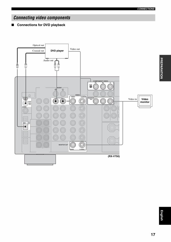
Connections for DVD playback
Connecting video components
AUDIO
DVD
DVD
COAXIAL
DVD
VIDEO
VIDEOS VIDEO
MONITOROUT
DVD
COMPONENT VIDEOPR PB Y
VIDEO S VIDEO
MONITOR OUT
DIGITALINPUT
LRCO
DVD player
Video monitor
(RX-V750)
Optical out
Video out
Audio out
Video in
Coaxial out
01EN_00_RXV750_GB.book Page 17 Thursday, February 12, 2004 5:15 PM
18
CONNECTIONS
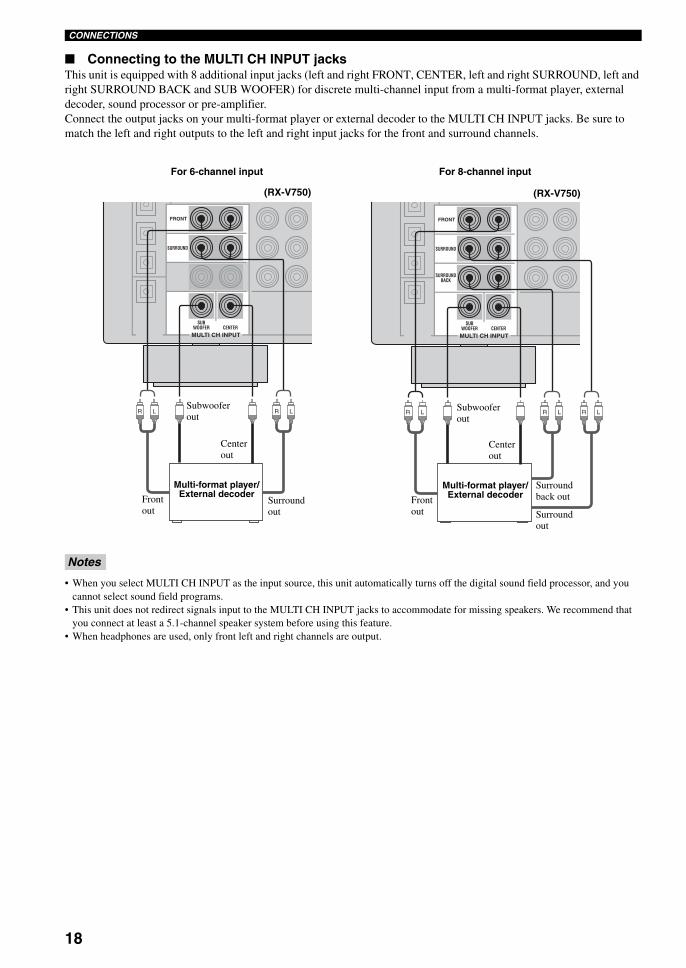
Connecting to the MULTI CH INPUT jacksThis unit is equipped with 8 additional input jacks (left and right FRONT, CENTER, left and right SURROUND, left and right SURROUND BACK and SUB WOOFER) for discrete multi-channel input from a multi-format player, external decoder, sound processor or pre-amplifier.Connect the output jacks on your multi-format player or external decoder to the MULTI CH INPUT jacks. Be sure to match the left and right outputs to the left and right input jacks for the front and surround channels.
• When you select MULTI CH INPUT as the input source, this unit automatically turns off the digital sound field processor, and you cannot select sound field programs.
• This unit does not redirect signals input to the MULTI CH INPUT jacks to accommodate for missing speakers. We recommend that you connect at least a 5.1-channel speaker system before using this feature.
• When headphones are used, only front left and right channels are output.
Notes
SUBWOOFER
SURROUND
FRONT
CENTERMULTI CH INPUT
LRLR
SUBWOOFER
SURROUNDBACK
SURROUND
FRONT
CENTERMULTI CH INPUT
LR LRLR
Multi-format player/External decoder
For 6-channel input
Front out
Surround out
Subwoofer out
Center out
Multi-format player/External decoderFront
out Surround out
Subwoofer out
Center out
Surround back out
For 8-channel input
(RX-V750) (RX-V750)
01EN_00_RXV750_GB.book Page 18 Thursday, February 12, 2004 5:15 PM

19
En
glish
CONNECTIONSP
RE
PAR
AT
ION
Connections for other video components
VIDEO AUX jacks (on the front panel)Use these jacks to connect any video source, such as a game console or video camera, to this unit.
AUDIO
DIGITALINPUT
DVD
OPTICAL DTV/CBL
VIDEO
VIDEOS VIDEO
DTV/CBL
COMPONENT VIDEO
DTV/CBL
IN
VCR 1
OUT
O LR
LR LR
Cable TV or satellite tuner
DVD recorder or VCR
Audio out
Video outOptical out
Audio out Video out
Video inAudio in
(RX-V750)
VIDEOS VIDEO OPTICALL AUDIO R
VIDEO AUX
OVS L R
Game console or video cameraVideo out
Audio out L
Audio out R
Optical out
S-Video out
01EN_00_RXV750_GB.book Page 19 Thursday, February 12, 2004 5:15 PM
20
CONNECTIONS
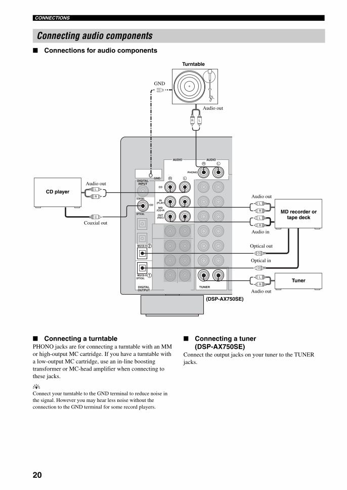
Connections for audio components
Connecting a turntablePHONO jacks are for connecting a turntable with an MM or high-output MC cartridge. If you have a turntable with a low-output MC cartridge, use an in-line boosting transformer or MC-head amplifier when connecting to these jacks.
yConnect your turntable to the GND terminal to reduce noise in the signal. However you may hear less noise without the connection to the GND terminal for some record players.
Connecting a tuner(DSP-AX750SE)
Connect the output jacks on your tuner to the TUNER jacks.
Connecting audio components
GND
AUDIO AUDIO
DIGITALINPUT
CD
COAXIAL
OPTICAL
MD/CD-R
MD/CD-ROPTICAL
OUT(REC)
IN(PLAY)
MD/CD-R
CD
PHONO
DIGITALOUTPUT
TUNER
L
R
L
R
L
R
O
L
R
O
LR
C
CD player
MD recorder or tape deck
(DSP-AX750SE)
Coaxial out
Audio out
Audio in
Optical in
Audio out
Turntable
GND
Audio out
Optical out
Tuner
Audio out
01EN_00_RXV750_GB.book Page 20 Thursday, February 12, 2004 5:15 PM
21
En
glish
CONNECTIONSP
RE
PAR
AT
ION
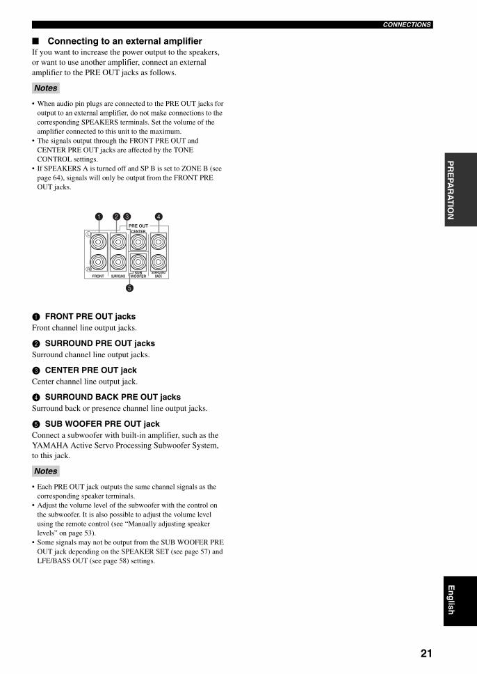
Connecting to an external amplifierIf you want to increase the power output to the speakers, or want to use another amplifier, connect an external amplifier to the PRE OUT jacks as follows.
• When audio pin plugs are connected to the PRE OUT jacks for output to an external amplifier, do not make connections to the corresponding SPEAKERS terminals. Set the volume of the amplifier connected to this unit to the maximum.
• The signals output through the FRONT PRE OUT and CENTER PRE OUT jacks are affected by the TONE CONTROL settings.
• If SPEAKERS A is turned off and SP B is set to ZONE B (see page 64), signals will only be output from the FRONT PRE OUT jacks.
1 FRONT PRE OUT jacksFront channel line output jacks.
2 SURROUND PRE OUT jacksSurround channel line output jacks.
3 CENTER PRE OUT jackCenter channel line output jack.
4 SURROUND BACK PRE OUT jacksSurround back or presence channel line output jacks.
5 SUB WOOFER PRE OUT jackConnect a subwoofer with built-in amplifier, such as the YAMAHA Active Servo Processing Subwoofer System, to this jack.
• Each PRE OUT jack outputs the same channel signals as the corresponding speaker terminals.
• Adjust the volume level of the subwoofer with the control on the subwoofer. It is also possible to adjust the volume level using the remote control (see “Manually adjusting speaker levels” on page 53).
• Some signals may not be output from the SUB WOOFER PRE OUT jack depending on the SPEAKER SET (see page 57) and LFE/BASS OUT (see page 58) settings.
Notes
Notes
CENTER
SUBWOOFERSURROUND
PRE OUT
FRONT
R
L
SURROUNDBACK
1 2 3
5
4
01EN_00_RXV750_GB.book Page 21 Thursday, February 12, 2004 5:15 PM
22
CONNECTIONS
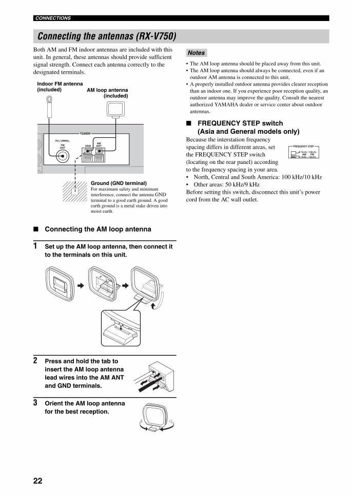
Both AM and FM indoor antennas are included with this unit. In general, these antennas should provide sufficient signal strength. Connect each antenna correctly to the designated terminals.
Connecting the AM loop antenna
1 Set up the AM loop antenna, then connect it to the terminals on this unit.
2 Press and hold the tab to insert the AM loop antenna lead wires into the AM ANT and GND terminals.
3 Orient the AM loop antenna for the best reception.
• The AM loop antenna should be placed away from this unit.• The AM loop antenna should always be connected, even if an
outdoor AM antenna is connected to this unit.• A properly installed outdoor antenna provides clearer reception
than an indoor one. If you experience poor reception quality, an outdoor antenna may improve the quality. Consult the nearest authorized YAMAHA dealer or service center about outdoor antennas.
FREQUENCY STEP switch(Asia and General models only)
Because the interstation frequency spacing differs in different areas, set the FREQUENCY STEP switch (locating on the rear panel) according to the frequency spacing in your area.• North, Central and South America: 100 kHz/10 kHz• Other areas: 50 kHz/9 kHzBefore setting this switch, disconnect this unit’s power cord from the AC wall outlet.
Connecting the antennas (RX-V750)
75Ω UNBAL.
FMANT
AMANTGND
TUNER
AM loop antenna(included)
Ground (GND terminal)For maximum safety and minimum interference, connect the antenna GND terminal to a good earth ground. A good earth ground is a metal stake driven into moist earth.
Indoor FM antenna (included)
Notes
FREQUENCY STEP
10KHZ / 100KHZ
9KHZ / 50KHZ
FMAM
01EN_00_RXV750_GB.book Page 22 Thursday, February 12, 2004 5:15 PM
23
En
glish
CONNECTIONSP
RE
PAR
AT
ION
Connecting the AC power cordPlug the power cord into an AC wall outlet.
AC OUTLET(S) (SWITCHED)U.K. and Australia models .............................. 1 OUTLETKorea model .............................................................. NoneOther models ................................................. 2 OUTLETS
Use these outlets to connect the power cords from your other components to this unit. Power to the AC OUTLET(S) is controlled by this unit’s STANDBY/ON (or SYSTEM POWER and STANDBY). The outlet(s) supply power to any connected component whenever this unit is turned on. The maximum power (total power consumption of components) that can be connected to the AC OUTLET(S) is:
China, Asia and General models .............................. 50 WKorea model ................................................................ N/AOther models ........................................................... 100 W
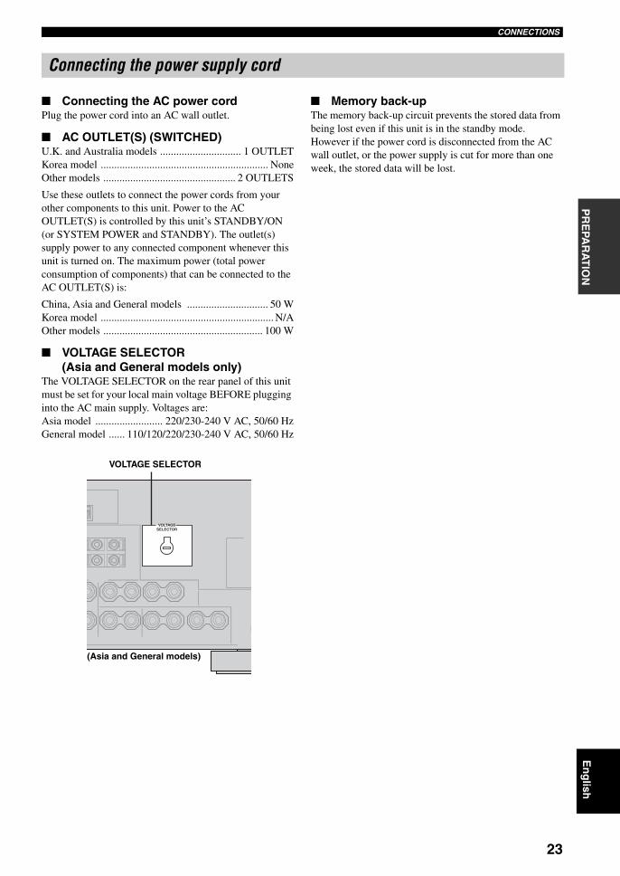
VOLTAGE SELECTOR (Asia and General models only)
The VOLTAGE SELECTOR on the rear panel of this unit must be set for your local main voltage BEFORE plugging into the AC main supply. Voltages are:Asia model ......................... 220/230-240 V AC, 50/60 HzGeneral model ...... 110/120/220/230-240 V AC, 50/60 Hz
Memory back-upThe memory back-up circuit prevents the stored data from being lost even if this unit is in the standby mode. However if the power cord is disconnected from the AC wall outlet, or the power supply is cut for more than one week, the stored data will be lost.
Connecting the power supply cord
VOLTAGESELECTOR
VOLTAGE SELECTOR
(Asia and General models)
01EN_00_RXV750_GB.book Page 23 Thursday, February 12, 2004 5:15 PM
24
CONNECTIONS
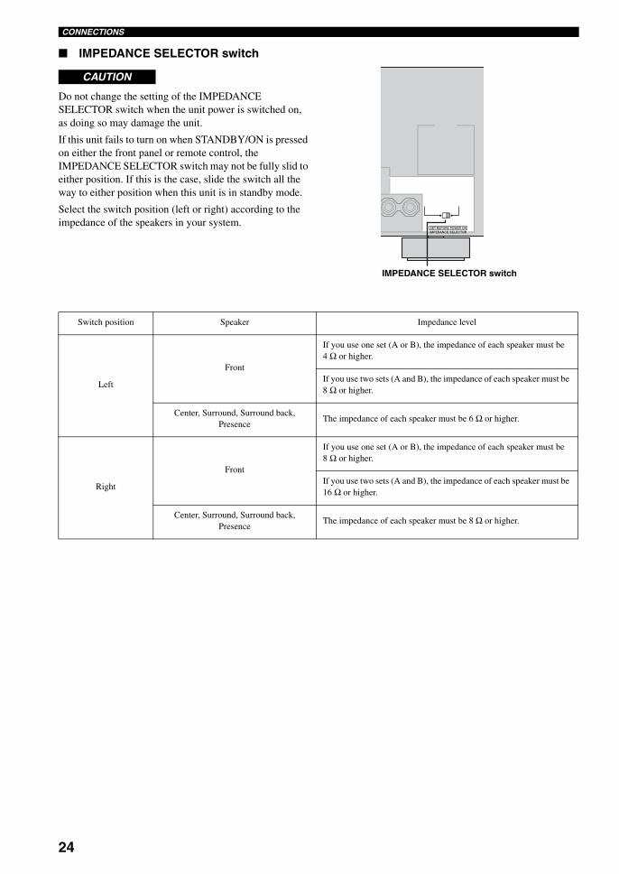
IMPEDANCE SELECTOR switch
Do not change the setting of the IMPEDANCE SELECTOR switch when the unit power is switched on, as doing so may damage the unit.
If this unit fails to turn on when STANDBY/ON is pressed on either the front panel or remote control, the IMPEDANCE SELECTOR switch may not be fully slid to either position. If this is the case, slide the switch all the way to either position when this unit is in standby mode.
Select the switch position (left or right) according to the impedance of the speakers in your system.
CAUTION
SET BEFORE POWER ONIMPEDANCE SELECTOR
IMPEDANCE SELECTOR switch
Switch position Speaker Impedance level
Left
Front
If you use one set (A or B), the impedance of each speaker must be 4 Ω or higher.
If you use two sets (A and B), the impedance of each speaker must be 8 Ω or higher.
The impedance of each speaker must be 6 Ω or higher.Center, Surround, Surround back,
Presence
Right
Front
If you use one set (A or B), the impedance of each speaker must be 8 Ω or higher.
If you use two sets (A and B), the impedance of each speaker must be 16 Ω or higher.
The impedance of each speaker must be 8 Ω or higher.Center, Surround, Surround back,
Presence
01EN_00_RXV750_GB.book Page 24 Thursday, February 12, 2004 5:15 PM
25
En
glish
CONNECTIONSP
RE
PAR
AT
ION
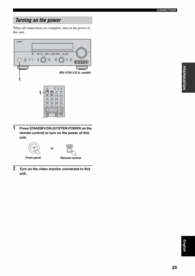
When all connections are complete, turn on the power of this unit.
1 Press STANDBY/ON (SYSTEM POWER on the remote control) to turn on the power of this unit.
2 Turn on the video monitor connected to this unit.
Turning on the power
AUTO/MAN'L MONO
S VIDEO VIDEO OPTICALL AUDIO R
MAN'L/AUTO FMLEVELNEXTEDIT
EFFECT
MEMORYFM/AMPRESET/TUNINGOPTIMIZER
MIC A/B/C/D/E
PROGRAM
l PRESET/TUNING h TUNING MODE
PURE DIRECTINPUT MODETONE CONTROLSTRAIGHTSPEAKERSPHONES
SILENT CINEMA
STANDBY/ON
BAMULTI CH
INPUT
VOLUME
VIDEO AUX
INPUT
1
TRANSMIT RE-NAME
INPUT MODESTANDBYSYSTEMPOWER
A B PHONO
CDMD/CD-RTUNERV-AUX
DVD
AMPPOWERPOWER
REC
AVTV
SELECT
VCR 1DTV/CBL DVR/VCR2
MULTI CH IN
SLEEP
CLEAR LEARN
1
(RX-V750 U.S.A. model)
STANDBY/ON
SYSTEMPOWER
or
Front panel Remote control
01EN_00_RXV750_GB.book Page 25 Thursday, February 12, 2004 5:15 PM
AUTO SETUP
26
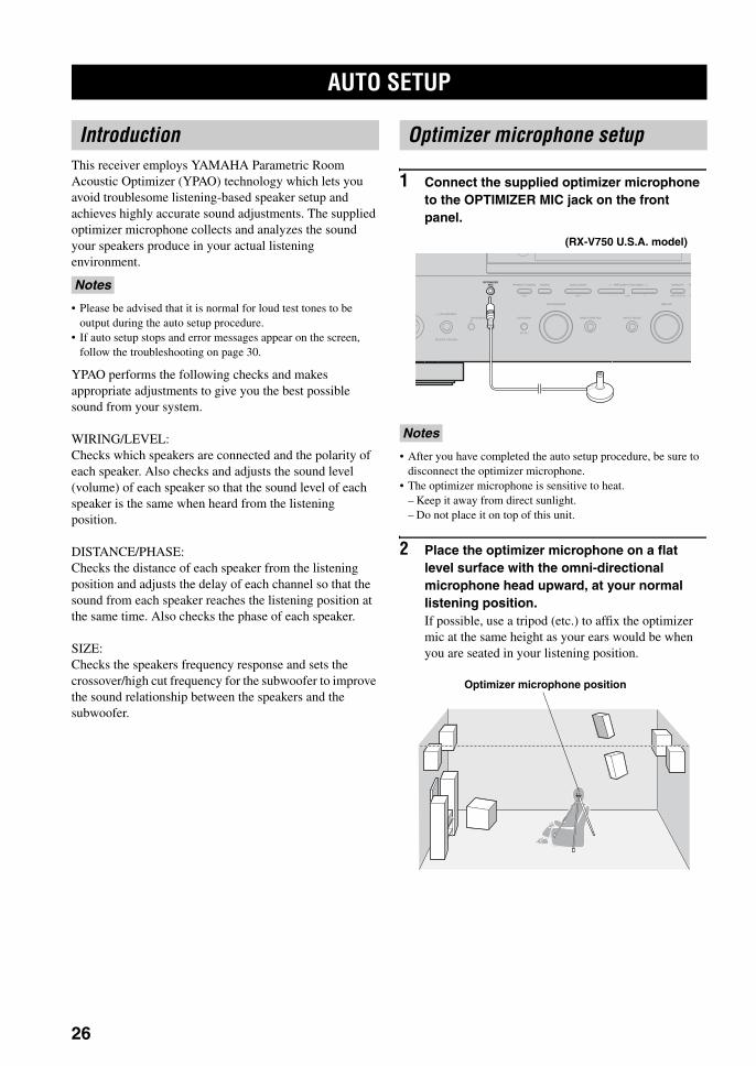
This receiver employs YAMAHA Parametric Room Acoustic Optimizer (YPAO) technology which lets you avoid troublesome listening-based speaker setup and achieves highly accurate sound adjustments. The supplied optimizer microphone collects and analyzes the sound your speakers produce in your actual listening environment.
• Please be advised that it is normal for loud test tones to be output during the auto setup procedure.
• If auto setup stops and error messages appear on the screen, follow the troubleshooting on page 30.
YPAO performs the following checks and makes appropriate adjustments to give you the best possible sound from your system.
WIRING/LEVEL:Checks which speakers are connected and the polarity of each speaker. Also checks and adjusts the sound level (volume) of each speaker so that the sound level of each speaker is the same when heard from the listening position.
DISTANCE/PHASE:Checks the distance of each speaker from the listening position and adjusts the delay of each channel so that the sound from each speaker reaches the listening position at the same time. Also checks the phase of each speaker.
SIZE:Checks the speakers frequency response and sets the crossover/high cut frequency for the subwoofer to improve the sound relationship between the speakers and the subwoofer.
1 Connect the supplied optimizer microphone to the OPTIMIZER MIC jack on the front panel.
• After you have completed the auto setup procedure, be sure to disconnect the optimizer microphone.
• The optimizer microphone is sensitive to heat.– Keep it away from direct sunlight.– Do not place it on top of this unit.
2 Place the optimizer microphone on a flat level surface with the omni-directional microphone head upward, at your normal listening position.If possible, use a tripod (etc.) to affix the optimizer mic at the same height as your ears would be when you are seated in your listening position.
AUTO SETUP
Introduction
Notes
Optimizer microphone setup
Notes
AMAN'L/AUTO FMLEVELNEXTEDIT
EFFECT
MEMORYFM/AMPRESET/TUNINGOPTIMIZER
MIC A/B/C/D/E
PROGRAM
l PRESET/TUNING h TU
INPUT MODETONE CONTROLSTRAIGHTSPEAKERSPHONES
SILENT CINEMA
Y
BA
INPUT
(RX-V750 U.S.A. model)
Optimizer microphone position
01EN_00_RXV750_GB.book Page 26 Thursday, February 12, 2004 5:15 PM
27
En
glish
AUTO SETUPP
RE
PAR
AT
ION
For best results, make sure the room is as quiet as possible during the auto setup procedure (YPAO). If there is too much ambient noise, the results may not be satisfactory.
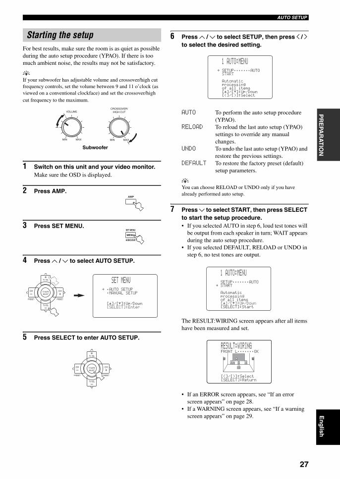
yIf your subwoofer has adjustable volume and crossover/high cut frequency controls, set the volume between 9 and 11 o’clock (as viewed on a conventional clockface) and set the crossover/high cut frequency to the maximum.
1 Switch on this unit and your video monitor.Make sure the OSD is displayed.
2 Press AMP.
3 Press SET MENU.
4 Press u / d to select AUTO SETUP.
5 Press SELECT to enter AUTO SETUP.
6 Press u / d to select SETUP, then press j / i to select the desired setting.
AUTO To perform the auto setup procedure (YPAO).
RELOAD To reload the last auto setup (YPAO) settings to override any manual changes.
UNDO To undo the last auto setup (YPAO) and restore the previous settings.
DEFAULT To restore the factory preset (default) setup parameters.
yYou can choose RELOAD or UNDO only if you have already performed auto setup.
7 Press d to select START, then press SELECT to start the setup procedure.• If you selected AUTO in step 6, loud test tones will
be output from each speaker in turn; WAIT appears during the auto setup procedure.
• If you selected DEFAULT, RELOAD or UNDO in step 6, no test tones are output.
The RESULT:WIRING screen appears after all items have been measured and set.
• If an ERROR screen appears, see “If an error screen appears” on page 28.
• If a WARNING screen appears, see “If a warning screen appears” on page 29.
Starting the setup
VOLUME
MIN MAX
CROSSOVER/HIGH CUT
MIN MAX
Subwoofer
AMP
SET MENU
A/B/C/D/E
MENU
TV VOL
PRESET PRESET
TV MUTE
TV VOL
SELECT
CHCH
+
+–
–
SET MENU
.;AUTOSETUP;MANUALSETUP
[ ]/[ ]:Up/Down[SELECT]:Enter
p
p
TV VOL
PRESET PRESET
TV MUTE
TV VOL
SELECT
CHCH
+
+–
–
1 AUTO:MENU
. SETUP;;;;;;;AUTOSTART
Automaticprocessingof all items
[ ]/[ ]:Up/Down[<]/[>]:Select
p
p
1 AUTO:MENU
SETUP;;;;;;;AUTO.STARTAutomaticprocessingof all items[]/[]:Up/Down[SELECT]:Start
p
p
FRONTL;;;;;;;OK
[<]/[>]:Select[SELECT]:Return
RESULT:WIRING
01EN_00_RXV750_GB.book Page 27 Thursday, February 12, 2004 5:15 PM
28
AUTO SETUP
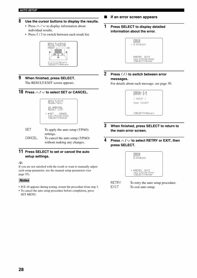
8 Use the cursor buttons to display the results.• Press u / d to display information about
individual results.• Press j / i to switch between each result list.
9 When finished, press SELECT.The RESULT:EXIT screen appears.
10 Press u / d to select SET or CANCEL.
SET To apply the auto setup (YPAO) settings.
CANCEL To cancel the auto setup (YPAO) without making any changes.
11 Press SELECT to set or cancel the auto setup settings.
yIf you are not satisfied with the result or want to manually adjust each setup parameter, use the manual setup parameters (see page 55).
• If E-10 appears during testing, restart the procedure from step 3.• To cancel the auto setup procedure before completion, press
SET MENU.
If an error screen appears
1 Press SELECT to display detailed information about the error.
2 Press j / i to switch between error messages.For details about each message, see page 30.
3 When finished, press SELECT to return to the main error screen.
4 Press u / d to select RETRY or EXIT, then press SELECT.
RETRY To retry the auto setup procedure.EXIT To exit auto setup.
Notes
FRONTL;;;;;;;OK
[<]/[>]:Select[SELECT]:Return
RESULT:WIRING
RESULT:EXIT
NOWARNINGRESULTLIST.)SETCANCEL[]/[]:Up/Down[SELECT]:Enter
p
p
ERROR.E-5:NOISY
)RETRYEXIT[]/[]:Up/Down[SELECT]:Enter
p
p
ERROR: E-5
<NOISY>
KeepSILENT
[SELECT]:Return
ERRORE-5:NOISY
.)RETRYEXIT[]/[]:Up/Down[SELECT]:Enter
p
p
01EN_00_RXV750_GB.book Page 28 Thursday, February 12, 2004 5:15 PM
29
En
glish
AUTO SETUPP
RE
PAR
AT
ION
If a warning screen appears
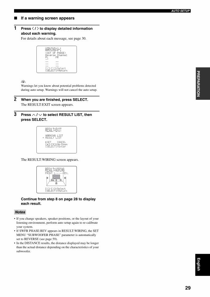
1 Press j / i to display detailed information about each warning.For details about each message, see page 30.
yWarnings let you know about potential problems detected during auto setup. Warnings will not cancel the auto setup.
2 When you are finished, press SELECT.The RESULT:EXIT screen appears.
3 Press u / d to select RESULT LIST, then press SELECT.
The RESULT:WIRING screen appears.
Continue from step 8 on page 28 to display each result.
• If you change speakers, speaker positions, or the layout of your listening environment, perform auto setup again to re-calibrate your system.
• If SWFR PHASE:REV appears in RESULT:WIRING, the SET MENU “SUBWOOFER PHASE” parameter is automatically set to REVERSE (see page 59).
• In the DISTANCE results, the distance displayed may be longer than the actual distance depending on the characteristics of your subwoofer.
Notes
WARNING:W-1<OUTOFPHASE>ReverseChannelFLFR--------------[<]/[>]:Select[SELECT]:Return
RESULT:EXIT
WARNINGLIST.RESULTLIST
)SETCANCEL[]/[]:Up/Down[SELECT]:Enter
p
p
FRONTL;;;;;REV.
[<]/[>]:Select[SELECT]:Return
RESULT:WIRING
01EN_00_RXV750_GB.book Page 29 Thursday, February 12, 2004 5:15 PM
30
AUTO SETUP
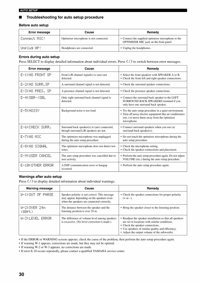
Troubleshooting for auto setup procedure
Before auto setup
Errors during auto setupPress SELECT to display detailed information about individual errors. Press j / i to switch between error messages.
Warnings after auto setupPress j / i to display detailed information about individual warnings.
• If the ERROR or WARNING screens appears, check the cause of the problem, then perform the auto setup procedure again.• If warning W-1 appears, corrections are made, but they may not be optimal.• If warning W-2 or W-3 appears, no corrections are made.• If error E-10 occurs repeatedly, please contact a qualified YAMAHA service center.
Error message Cause Remedy
Connect MIC! Optimizer microphone is not connected. • Connect the supplied optimizer microphone to the OPTIMIZER MIC jack on the front panel.
Unplug HP! Headphones are connected. • Unplug the headphones.
Error message Cause Remedy
E-1:NO FRONT SP Front L/R channel signal(s) is (are) not detected.
• Select the front speakers with SPEAKER A or B.• Check the front left and right speaker connections.
E-2:NO SURR.SP A surround channel signal is not detected. • Check the surround speaker connections.
E-3:NO PRES. SP A presence channel signal is not detected. • Check the presence speaker connections.
E-4:SBR->SBL Only right surround back channel signal is detected.
• Connect the surround back speaker to the LEFT SURROUND BACK SPEAKERS terminal if you only have one surround back speaker.
E-5:NOISY Background noise is too loud. • Try the auto setup procedure in a quiet environment.• Turn off noisy electric equipment like air conditioners
(etc.) or move them away from the optimizer microphone.
E-6:CHECK SURR. Surround back speaker(s) is (are) connected, though surround L/R speakers are not.
• Connect surround speakers when you use (a) surround back speaker(s).
E-7:NO MIC The optimizer microphone was unplugged during the auto setup procedure.
• Do not touch the optimizer microphone during the auto setup procedure.
E-8:NO SIGNAL The optimizer microphone does not detect test tones.
• Check the microphone setting.• Check the speaker connections and placement.
E-9:USER CANCEL The auto setup procedure was cancelled due to user activity.
• Perform the auto setup procedure again. Do not adjust VOLUME (etc.) during the auto setup procedure.
E-10:OTHER ERROR A DSP communication error or hangup occurred.
• Perform the auto setup procedure again.
Warning message Cause Remedy
W-1:OUT OF PHASE Speaker polarity is not correct. This message may appear depending on the speakers even when the speakers are connected correctly.
• Check the speaker connections for proper polarity (+ or –).
W-2:OVER 24m (80ft)
The distance between the speaker and the listening position is over 24 m.
• Bring the speaker closer to the listening position.
W-3:LEVEL ERROR The difference of volume level among speakers is excessive. (No level correction is made.)
• Readjust the speaker installation so that all speakers are set in locations with similar conditions.
• Check the speaker connections.• Use speakers of similar quality and efficiency.• Adjust the output volume of the subwoofer.
01EN_00_RXV750_GB.book Page 30 Thursday, February 12, 2004 5:15 PM
PLAYBACK
31
En
glish
BA
SIC
O
PE
RA
TIO
N
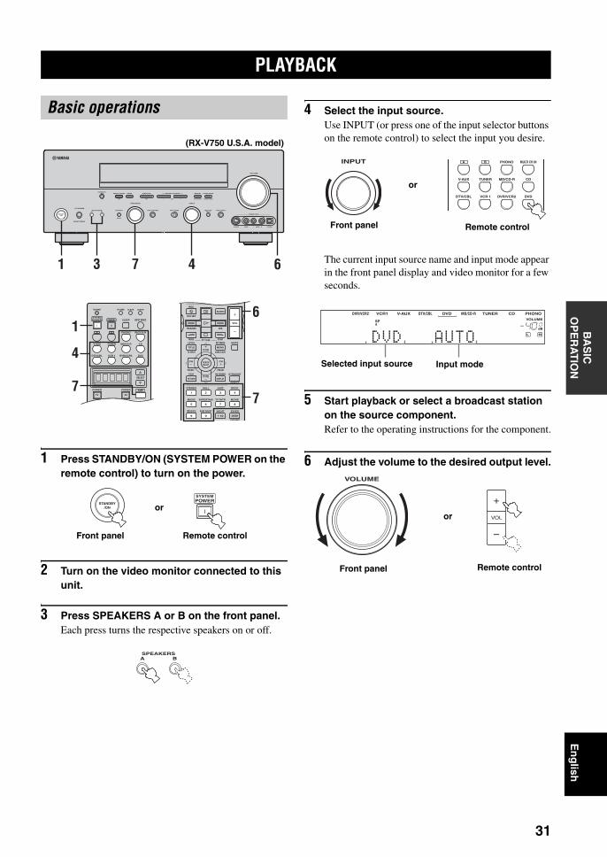
1 Press STANDBY/ON (SYSTEM POWER on the remote control) to turn on the power.
2 Turn on the video monitor connected to this unit.
3 Press SPEAKERS A or B on the front panel.Each press turns the respective speakers on or off.
4 Select the input source.Use INPUT (or press one of the input selector buttons on the remote control) to select the input you desire.
The current input source name and input mode appear in the front panel display and video monitor for a few seconds.
5 Start playback or select a broadcast station on the source component.Refer to the operating instructions for the component.
6 Adjust the volume to the desired output level.
PLAYBACK
Basic operations
AUTO/MAN'L MONO
S VIDEO VIDEO OPTICALL AUDIO R
MAN'L/AUTO FMLEVELNEXTEDIT
EFFECT
MEMORYFM/AMPRESET/TUNINGOPTIMIZER
MIC A/B/C/D/E
PROGRAM
l PRESET/TUNING h TUNING MODE
PURE DIRECTINPUT MODETONE CONTROLSTRAIGHTSPEAKERSPHONES
SILENT CINEMA
STANDBY/ON
BAMULTI CH
INPUT
VOLUME
VIDEO AUX
INPUT
1 7 43 6
TRANSMIT RE-NAME
INPUT MODESTANDBYSYSTEMPOWER
A B PHONO
CDMD/CD-RTUNERV-AUX
DVD
AMPPOWERPOWER
REC
AVTV
SELECT
VCR 1DTV/CBL DVR/VCR2
MULTI CH IN
SLEEP
CLEAR LEARNREC
AUDIO
MUTE
MENUTITLE
CH CH
VOL
DISC SKIP
FREQ/RDS EON
STARTSET MENULEVEL
A/B/C/D/ETV INPUT
MODE PTY SEEK
TV VOL
PRESET
TEST ON SCREEN STRAIGHT
ROCKJAZZHALLSTEREO
4321
8
10
7
09
65
ENTER
MOVIETV THTRMUSIC ENTERTAIN
EX/ESNIGHTq/DTS PURE DIRECT
EFFECT
CHP/INDEX
DISPLAYRETURN
PRESET
TV MUTESELECT
TV VOL
AVTV
16
7
4
7
(RX-V750 U.S.A. model)
STANDBY/ON
SYSTEMPOWER
Front panel Remote control
or
SPEAKERSBA
INPUT A B PHONO
CDMD/CD-RTUNERV-AUX
DVDVCR 1DTV/CBL DVR/VCR2
MULTI CH IN
Front panel Remote control
or
CDTUNERMD/CD-RDVD
HiFi DSP
DTV/CBLV-AUXVCR1DVR/VCR29624
q PLq EX
MATRIX DISCRETE SILENT CINEMA NIGHT ZONE2 PTY HOLD AUTO
PS RT CT EONPTY
TUNED STEREO MUTE VOLUMEMEMORY
SLEEPVIRTUAL
PCMq PL q PL x
A BSP
ftmSdB
dB96/24
LFEL C RSL SB SR
q DIGITAL
t
01 DDVD D AUTOO00
PHONO
Selected input source Input mode
VOLUME
VOL
+
–
or
Remote controlFront panel
01EN_00_RXV750_GB.book Page 31 Thursday, February 12, 2004 5:15 PM
32
PLAYBACK
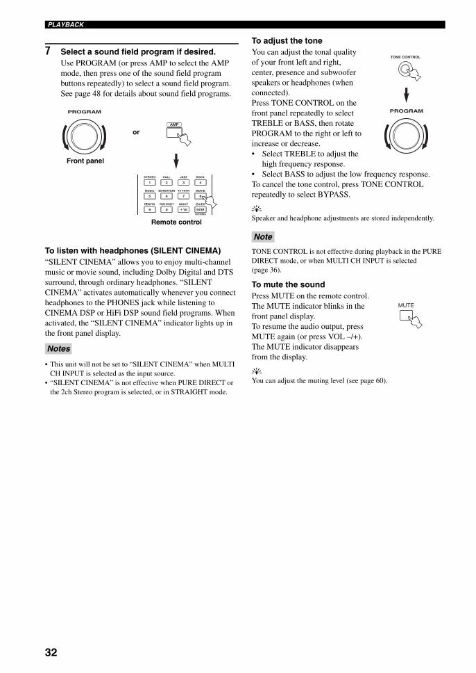
7 Select a sound field program if desired.Use PROGRAM (or press AMP to select the AMP mode, then press one of the sound field program buttons repeatedly) to select a sound field program. See page 48 for details about sound field programs.
To listen with headphones (SILENT CINEMA)“SILENT CINEMA” allows you to enjoy multi-channel music or movie sound, including Dolby Digital and DTS surround, through ordinary headphones. “SILENT CINEMA” activates automatically whenever you connect headphones to the PHONES jack while listening to CINEMA DSP or HiFi DSP sound field programs. When activated, the “SILENT CINEMA” indicator lights up in the front panel display.
• This unit will not be set to “SILENT CINEMA” when MULTI CH INPUT is selected as the input source.
• “SILENT CINEMA” is not effective when PURE DIRECT or the 2ch Stereo program is selected, or in STRAIGHT mode.
To adjust the toneYou can adjust the tonal quality of your front left and right, center, presence and subwoofer speakers or headphones (when connected).Press TONE CONTROL on the front panel repeatedly to select TREBLE or BASS, then rotate PROGRAM to the right or left to increase or decrease.• Select TREBLE to adjust the
high frequency response.• Select BASS to adjust the low frequency response.To cancel the tone control, press TONE CONTROL repeatedly to select BYPASS.
ySpeaker and headphone adjustments are stored independently.
TONE CONTROL is not effective during playback in the PURE DIRECT mode, or when MULTI CH INPUT is selected (page 36).
To mute the soundPress MUTE on the remote control. The MUTE indicator blinks in the front panel display.To resume the audio output, press MUTE again (or press VOL –/+). The MUTE indicator disappears from the display.
yYou can adjust the muting level (see page 60).
Notes
PROGRAM
ROCKJAZZHALLSTEREO
4321
8
10
7
09
65
ENTER
MOVIETV THTRMUSIC ENTERTAIN
EX/ESNIGHTq/DTS PURE DIRECT
CHP/INDEX
AMP
Remote control
Front panel
or
Note
TONE CONTROL
PROGRAM
MUTE
01EN_00_RXV750_GB.book Page 32 Thursday, February 12, 2004 5:15 PM
33
En
glish
PLAYBACKB
AS
IC
OP
ER
AT
ION
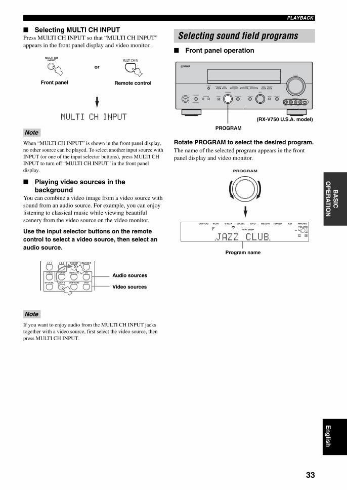
Selecting MULTI CH INPUTPress MULTI CH INPUT so that “MULTI CH INPUT” appears in the front panel display and video monitor.
MULTI CH INPUT
When “MULTI CH INPUT” is shown in the front panel display, no other source can be played. To select another input source with INPUT (or one of the input selector buttons), press MULTI CH INPUT to turn off “MULTI CH INPUT” in the front panel display.
Playing video sources in the background
You can combine a video image from a video source with sound from an audio source. For example, you can enjoy listening to classical music while viewing beautiful scenery from the video source on the video monitor.
Use the input selector buttons on the remote control to select a video source, then select an audio source.
If you want to enjoy audio from the MULTI CH INPUT jacks together with a video source, first select the video source, then press MULTI CH INPUT.
Front panel operation
Rotate PROGRAM to select the desired program.The name of the selected program appears in the front panel display and video monitor.
Note
Note
MULTI CHINPUT MULTI CH IN
Front panel Remote control
or
A B PHONO
CDMD/CD-RTUNERV-AUX
DVDVCR 1DTV/CBL DVR/VCR2
MULTI CH IN
Audio sources
Video sources
Selecting sound field programs
AUTO/MAN'L MONO
S VIDEO VIDEO OPTICALL AUDIO R
MAN'L/AUTO FMLEVELNEXTEDIT
EFFECT
MEMORYFM/AMPRESET/TUNINGOPTIMIZER
MIC A/B/C/D/E
PROGRAM
l PRESET/TUNING h TUNING MODE
PURE DIRECTINPUT MODETONE CONTROLSTRAIGHTSPEAKERSPHONES
SILENT CINEMA
STANDBY/ON
BAMULTI CH
INPUT
VOLUME
VIDEO AUX
INPUT
PROGRAM
(RX-V750 U.S.A. model)
PHONOCDTUNERMD/CD-RDVD
HiFi DSP
DTV/CBLV-AUXVCR1DVR/VCR29624
q PLq EX
MATRIX DISCRETE SILENT CINEMA NIGHT ZONE2 PTY HOLD AUTO
PS RT CT EONPTY
TUNED STEREO MUTE VOLUMEMEMORY
SLEEPVIRTUAL
PCMq PL q PL x
A BSP
ftmSdB
dB96/24
LFEL C RSL SB SR
q DIGITAL
t
01 DJAZZACLUBO00
Program name
PROGRAM
01EN_00_RXV750_GB.book Page 33 Thursday, February 12, 2004 5:15 PM
34
PLAYBACK
Remote control operation
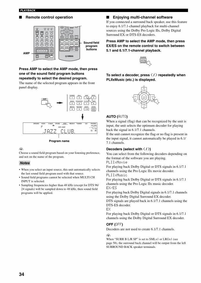
Press AMP to select the AMP mode, then press one of the sound field program buttons repeatedly to select the desired program.The name of the selected program appears in the front panel display.
yChoose a sound field program based on your listening preference, and not on the name of the program.
• When you select an input source, this unit automatically selects the last sound field program used with that source.
• Sound field programs cannot be selected when MULTI CH INPUT is selected.
• Sampling frequencies higher than 48 kHz (except for DTS 96/24 signals) will be sampled down to 48 kHz, then sound field programs will be applied.
Enjoying multi-channel softwareIf you connected a surround back speaker, use this feature to enjoy 6.1/7.1-channel playback for multi-channel sources using the Dolby Pro Logic IIx, Dolby Digital Surround EX or DTS-ES decoders.
Press AMP to select the AMP mode, then press EX/ES on the remote control to switch between 5.1 and 6.1/7.1-channel playback.
To select a decoder, press j / i repeatedly when PLIIxMusic (etc.) is displayed.
AUTO (AUTO)When a signal (flag) that can be recognized by the unit is input, the unit selects the optimum decoder for playing back the signal in 6.1/7.1 channels.If the unit cannot recognize the flag or no flag is present in the input signal, it cannot automatically be played in 6.1/7.1 channels.
Decoders (select with j / i)You can select from the following decoders depending on the format of the software you are playing.PLIIxMovieFor playing back Dolby Digital or DTS signals in 6.1/7.1 channels using the Pro Logic IIx movie decoder.PLIIxMusicFor playing back Dolby Digital or DTS signals in 6.1/7.1 channels using the Pro Logic IIx music decoder.EX/ESFor playing back Dolby Digital signals in 6.1/7.1 channels using the Dolby Digital Surround EX decoder.DTS signals are played back in 6.1/7.1 channels using the DTS-ES decoder.EXFor playing back Dolby Digital or DTS signals in 6.1/7.1 channels using the Dolby Digital Surround EX decoder.
OFF (OFF)Decoders are not used to create 6.1/7.1 channels.
yWhen “SURR B L/R SP” is set to SMLx1 or LRGx1 (see page 58), the surround back channel will be output from the left SURROUND BACK speaker terminals.
Notes
TRANSMIT RE-NAME
INPUT MODESTANDBYSYSTEMPOWER
A B PHONO
CDMD/CD-RTUNERV-AUX
DVD
AMPPOWERPOWER
REC
AUDIO
AVTV
SELECT
VCR 1DTV/CBL DVR/VCR2
MULTI CH IN
SLEEP
CLEAR LEARN
MUTE
MENUTITLE
CH CH
SET MENULEVEL
A/B/C/D/ETV INPUTTV VOL
PRESET
TEST ON SCREEN STRAIGHT
ROCKJAZZHALLSTEREO
4321
8
10
7
09
65
ENTER
MOVIETV THTRMUSIC ENTERTAIN
EX/ESNIGHTq/DTS PURE DIRECT
EFFECT
CHP/INDEX
DISPLAYRETURN
PRESET
TV MUTESELECT
TV VOL
Sound field program buttons
AMP
PHONOCDTUNERMD/CD-RDVD
HiFi DSP
DTV/CBLV-AUXVCR1DVR/VCR29624
q PLq EX
MATRIX DISCRETE SILENT CINEMA NIGHT ZONE2 PTY HOLD AUTO
PS RT CT EONPTY
TUNED STEREO MUTE VOLUMEMEMORY
SLEEPVIRTUAL
PCMq PL q PL x
A BSP
ftmSdB
dB96/24
LFEL C RSL SB SR
q DIGITAL
t
01 DJAZZACLUBO00
ROCKJAZZHALLSTEREO
4321
8
10
7
09
65
ENTER
MOVIETV THTRMUSIC ENTERTAIN
EX/ESNIGHTq/DTS PURE DIRECT
CHP/INDEX
AMP
Program name
ENTER
EX/ES
CHP/INDEX
TV VOL
PRESET PRESET
TV MUTE
TV VOL
SELECT
CHCH
+
+–
–
01EN_00_RXV750_GB.book Page 34 Thursday, February 12, 2004 5:15 PM

35
En
glish
PLAYBACKB
AS
IC
OP
ER
AT
ION
• Some 6.1-channel compatible discs do not have a signal (flag) which this unit can automatically detect. When playing these kinds of discs with 6.1-channel, select a decoder (PLIIx Movie, PLIIx Music, EX/ES or EX) manually.
• 6.1-channel playback is not possible even if EX/ES is pressed in the following cases:– When “SURR L/R SP” (see page 57) or “SURR B L/R SP”
(see page 58) is set to NONE.– When the source connected to the MULTI CH INPUT jack is
being played.– When the source being played does not contain surround left
and right channel signals.– When a Dolby Digital KARAOKE source is being played.– When “2ch Stereo” or PURE DIRECT is selected.
• When the power of this unit is turned off, the input mode will be reset to AUTO.
• When the DTS-ES decoder is applied to DTS 96/24 signals, you cannot use the DTS 96/24 decoding feature.
• The Pro Logic IIx decoder is not available when “SURR B L/R SP” is set to NONE (see page 58).
• PLIIxMovie cannot be selected when “SURR B L/R SP” is set to SMLx1 or LRGx1 (see page 58).
Enjoying 2-channel softwareSignals input from 2-channel sources can also be played back on multiple channels.
Press q/DTS on the remote control to select the decoder.
You can select from the following decoders depending on the type of software you are playing and your personal preference.
PRO LOGIC SUR. STANDARD
Standard processing for Dolby Surround sources.
PRO LOGIC SUR. ENHANCED
CINEMA DSP enhanced processing for Dolby Surround sources.
PRO LOGIC IIx Movie*
Dolby Pro Logic II/IIx processing for movie software.
PRO LOGIC IIx Music*
Dolby Pro Logic II/IIx processing for music software.
PRO LOGIC IIx Game*
Dolby Pro Logic II/IIx processing for game software.
DTS Neo:6 Cinema
DTS processing for movie software.
DTS Neo:6 Music
DTS processing for music software.
* Use the PLII/PLIIx parameter to select the Pro Logic II or Pro Logic IIx decoders (see page 78).
The Pro Logic IIx decoder is not available when “SURR B L/R SP” is set to NONE (see page 58).
Notes
Note
/DTS
9
01EN_00_RXV750_GB.book Page 35 Thursday, February 12, 2004 5:15 PM
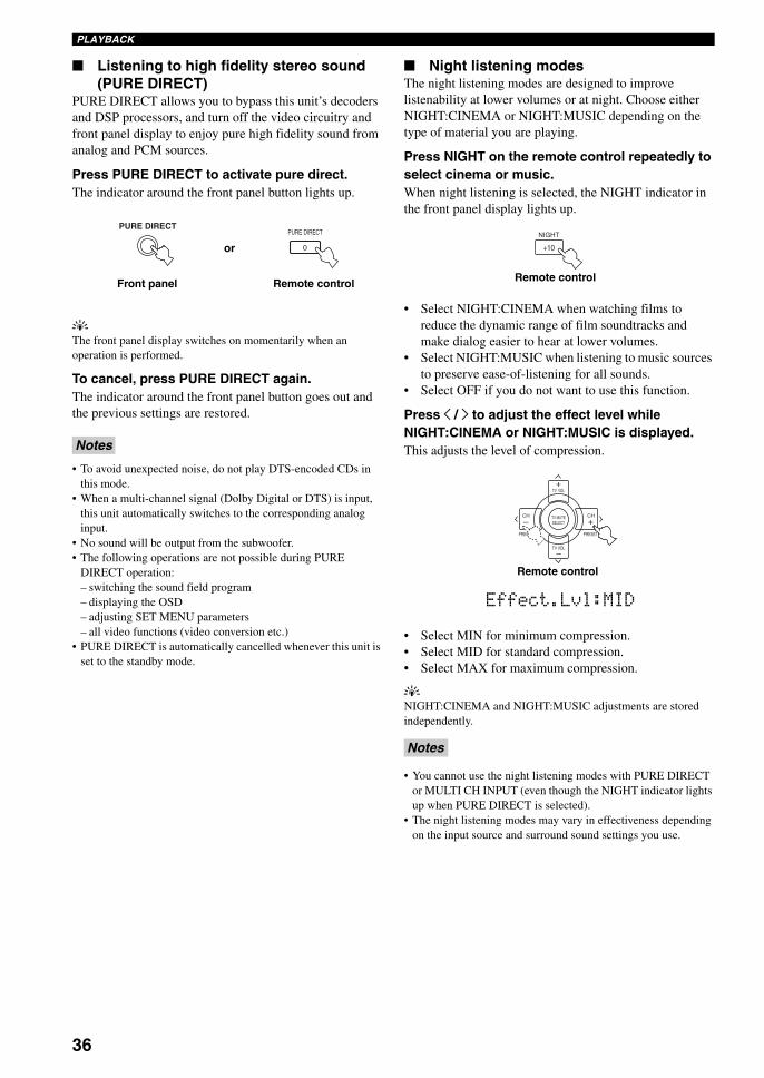
36
PLAYBACK
Listening to high fidelity stereo sound (PURE DIRECT)
PURE DIRECT allows you to bypass this unit’s decoders and DSP processors, and turn off the video circuitry and front panel display to enjoy pure high fidelity sound from analog and PCM sources.
Press PURE DIRECT to activate pure direct.The indicator around the front panel button lights up.
yThe front panel display switches on momentarily when an operation is performed.
To cancel, press PURE DIRECT again.The indicator around the front panel button goes out and the previous settings are restored.
• To avoid unexpected noise, do not play DTS-encoded CDs in this mode.
• When a multi-channel signal (Dolby Digital or DTS) is input, this unit automatically switches to the corresponding analog input.
• No sound will be output from the subwoofer.• The following operations are not possible during PURE
DIRECT operation:– switching the sound field program– displaying the OSD– adjusting SET MENU parameters– all video functions (video conversion etc.)
• PURE DIRECT is automatically cancelled whenever this unit is set to the standby mode.
Night listening modesThe night listening modes are designed to improve listenability at lower volumes or at night. Choose either NIGHT:CINEMA or NIGHT:MUSIC depending on the type of material you are playing.
Press NIGHT on the remote control repeatedly to select cinema or music.When night listening is selected, the NIGHT indicator in the front panel display lights up.
• Select NIGHT:CINEMA when watching films to reduce the dynamic range of film soundtracks and make dialog easier to hear at lower volumes.
• Select NIGHT:MUSIC when listening to music sources to preserve ease-of-listening for all sounds.
• Select OFF if you do not want to use this function.
Press j / i to adjust the effect level while NIGHT:CINEMA or NIGHT:MUSIC is displayed.This adjusts the level of compression.
• Select MIN for minimum compression.• Select MID for standard compression.• Select MAX for maximum compression.
yNIGHT:CINEMA and NIGHT:MUSIC adjustments are stored independently.
• You cannot use the night listening modes with PURE DIRECT or MULTI CH INPUT (even though the NIGHT indicator lights up when PURE DIRECT is selected).
• The night listening modes may vary in effectiveness depending on the input source and surround sound settings you use.
Notes
PURE DIRECTPURE DIRECT
0
Front panel Remote control
or
Notes
Remote control
NIGHT
+10
TV VOL
PRESET PRESET
TV MUTE
TV VOL
SELECT
CHCH
+
+–
–
Remote control
Effect.Lvl:MID
01EN_00_RXV750_GB.book Page 36 Thursday, February 12, 2004 5:15 PM
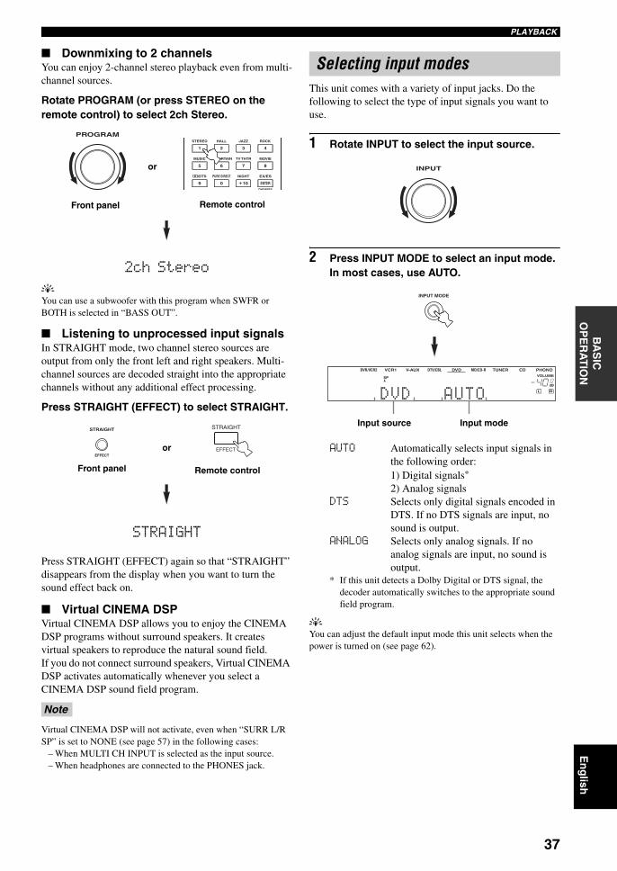
37
En
glish
PLAYBACKB
AS
IC
OP
ER
AT
ION
Downmixing to 2 channelsYou can enjoy 2-channel stereo playback even from multi-channel sources.
Rotate PROGRAM (or press STEREO on the remote control) to select 2ch Stereo.
2ch Stereo
yYou can use a subwoofer with this program when SWFR or BOTH is selected in “BASS OUT”.
Listening to unprocessed input signalsIn STRAIGHT mode, two channel stereo sources are output from only the front left and right speakers. Multi-channel sources are decoded straight into the appropriate channels without any additional effect processing.
Press STRAIGHT (EFFECT) to select STRAIGHT.
STRAIGHT
Press STRAIGHT (EFFECT) again so that “STRAIGHT” disappears from the display when you want to turn the sound effect back on.
Virtual CINEMA DSPVirtual CINEMA DSP allows you to enjoy the CINEMA DSP programs without surround speakers. It creates virtual speakers to reproduce the natural sound field.If you do not connect surround speakers, Virtual CINEMA DSP activates automatically whenever you select a CINEMA DSP sound field program.
Virtual CINEMA DSP will not activate, even when “SURR L/R SP” is set to NONE (see page 57) in the following cases:
– When MULTI CH INPUT is selected as the input source.– When headphones are connected to the PHONES jack.
This unit comes with a variety of input jacks. Do the following to select the type of input signals you want to use.
1 Rotate INPUT to select the input source.
2 Press INPUT MODE to select an input mode. In most cases, use AUTO.
AUTO Automatically selects input signals in the following order:1) Digital signals*
2) Analog signalsDTS Selects only digital signals encoded in
DTS. If no DTS signals are input, no sound is output.
ANALOG Selects only analog signals. If no analog signals are input, no sound is output.
* If this unit detects a Dolby Digital or DTS signal, the decoder automatically switches to the appropriate sound field program.
yYou can adjust the default input mode this unit selects when the power is turned on (see page 62).
Note
ROCKJAZZHALLSTEREO
4321
8
10
7
09
65
ENTER
MOVIETV THTRMUSIC ENTERTAIN
EX/ESNIGHTq/DTS PURE DIRECT
CHP/INDEX
Front panel
or
PROGRAM
Remote control
EFFECT
STRAIGHT STRAIGHT
EFFECT
Front panel Remote control
or
Selecting input modes
INPUT
INPUT MODE
CDTUNERMD/CD-RDVD
HiFi DSP
DTV/CBLV-AUXVCR1DVR/VCR29624
q PLq EX
MATRIX DISCRETE SILENT CINEMA NIGHT ZONE2 PTY HOLD AUTO
PS RT CT EONPTY
TUNED STEREO MUTE VOLUMEMEMORY
SLEEPVIRTUAL
PCMq PL q PL x
A BSP
ftmSdB
dB96/24
LFEL C RSL SB SR
q DIGITAL
t
01 DDVD D AUTOO00
PHONO
Input modeInput source
01EN_00_RXV750_GB.book Page 37 Thursday, February 12, 2004 5:15 PM
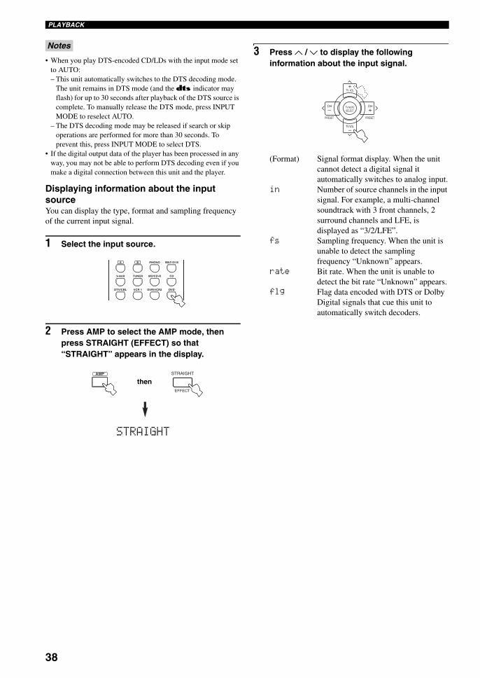
38
PLAYBACK
• When you play DTS-encoded CD/LDs with the input mode set to AUTO:– This unit automatically switches to the DTS decoding mode.
The unit remains in DTS mode (and the t indicator may flash) for up to 30 seconds after playback of the DTS source is complete. To manually release the DTS mode, press INPUT MODE to reselect AUTO.
– The DTS decoding mode may be released if search or skip operations are performed for more than 30 seconds. To prevent this, press INPUT MODE to select DTS.
• If the digital output data of the player has been processed in any way, you may not be able to perform DTS decoding even if you make a digital connection between this unit and the player.
Displaying information about the input sourceYou can display the type, format and sampling frequency of the current input signal.
1 Select the input source.
2 Press AMP to select the AMP mode, then press STRAIGHT (EFFECT) so that “STRAIGHT” appears in the display.
STRAIGHT
3 Press u / d to display the following information about the input signal.
(Format) Signal format display. When the unit cannot detect a digital signal it automatically switches to analog input.
in Number of source channels in the input signal. For example, a multi-channel soundtrack with 3 front channels, 2 surround channels and LFE, is displayed as “3/2/LFE”.
fs Sampling frequency. When the unit is unable to detect the sampling frequency “Unknown” appears.
rate Bit rate. When the unit is unable to detect the bit rate “Unknown” appears.
flg Flag data encoded with DTS or Dolby Digital signals that cue this unit to automatically switch decoders.
Notes
A B PHONO
CDMD/CD-RTUNERV-AUX
DVDVCR 1DTV/CBL DVR/VCR2
MULTI CH IN
STRAIGHT
EFFECT
AMP
then
TV VOL
PRESET PRESET
TV MUTE
TV VOL
SELECT
CHCH
+
+–
–
01EN_00_RXV750_GB.book Page 38 Thursday, February 12, 2004 5:15 PM
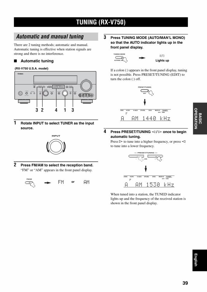
TUNING (RX-V750)
39
En
glish
BA
SIC
O
PE
RA
TIO
N
There are 2 tuning methods; automatic and manual.Automatic tuning is effective when station signals are strong and there is no interference.
Automatic tuning
1 Rotate INPUT to select TUNER as the input source.
2 Press FM/AM to select the reception band.“FM” or “AM” appears in the front panel display.
3 Press TUNING MODE (AUTO/MAN’L MONO) so that the AUTO indicator lights up in the front panel display.
If a colon (:) appears in the front panel display, tuning is not possible. Press PRESET/TUNING (EDIT) to turn the colon (:) off.
4 Press PRESET/TUNING l / h once to begin automatic tuning.Press h to tune into a higher frequency, or press l to tune into a lower frequency.
When tuned into a station, the TUNED indicator lights up and the frequency of the received station is shown in the front panel display.
TUNING (RX-V750)
Automatic and manual tuning
AUTO/MAN'L MONO
S VIDEO VIDEO OPTICALL AUDIO R
MAN'L/AUTO FMLEVELNEXTEDIT
EFFECT
MEMORYFM/AMPRESET/TUNINGOPTIMIZER
MIC A/B/C/D/E
PROGRAM
l PRESET/TUNING h TUNING MODE
PURE DIRECTINPUT MODETONE CONTROLSTRAIGHTSPEAKERSPHONES
SILENT CINEMA
STANDBY/ON
BAMULTI CH
INPUT
VOLUME
VIDEO AUX
INPUT
3 312 4
(RX-V750 U.S.A. model)
INPUT
FM/AM
or AMFM
AUTO/MAN'L MONO
TUNING MODE
AUTO
Lights up
EDIT
PRESET/TUNING
TUNERMD/CD-RDVD
HiFi DSP
DTV/CBLV-AUXVCR1R/VCR2T CINEMA NIGHT ZONE2 PTY HOLD AUTO
PS RT CT EONPTY
TUNED STEREO MEM
SLEEPTUAL A B
SP
A1 -AAM11440kkHz
TUNERMD/CD-RDVD
HiFi DSP
DTV/CBLV-AUXVCR1R/VCR2T CINEMA NIGHT ZONE2 PTY HOLD AUTO
PS RT CT EONPTY
TUNED STEREO MEM
SLEEPTUAL A B
SP
A1 -AAM11530kkHz
LEVEL
l PRESET/TUNING h
01EN_00_RXV750_GB.book Page 39 Thursday, February 12, 2004 5:15 PM
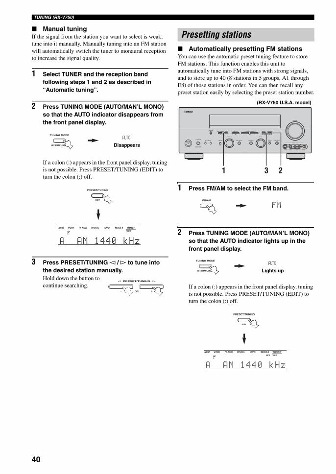
40
TUNING (RX-V750)
Manual tuningIf the signal from the station you want to select is weak, tune into it manually. Manually tuning into an FM station will automatically switch the tuner to monaural reception to increase the signal quality.
1 Select TUNER and the reception band following steps 1 and 2 as described in “Automatic tuning”.
2 Press TUNING MODE (AUTO/MAN’L MONO) so that the AUTO indicator disappears from the front panel display.
If a colon (:) appears in the front panel display, tuning is not possible. Press PRESET/TUNING (EDIT) to turn the colon (:) off.
3 Press PRESET/TUNING l / h to tune into the desired station manually.Hold down the button to continue searching.
Automatically presetting FM stationsYou can use the automatic preset tuning feature to store FM stations. This function enables this unit to automatically tune into FM stations with strong signals, and to store up to 40 (8 stations in 5 groups, A1 through E8) of those stations in order. You can then recall any preset station easily by selecting the preset station number.
1 Press FM/AM to select the FM band.
2 Press TUNING MODE (AUTO/MAN’L MONO) so that the AUTO indicator lights up in the front panel display.
If a colon (:) appears in the front panel display, tuning is not possible. Press PRESET/TUNING (EDIT) to turn the colon (:) off.
AUTO/MAN'L MONO
TUNING MODEAUTO
Disappears
EDIT
PRESET/TUNING
TUNERMD/CD-RDVD
HiFi DSP
DTV/CBLV-AUXVCR1R/VCR2T CINEMA NIGHT ZONE2 PTY HOLD AUTO
PS RT CT EONPTY
TUNED STEREO MEM
SLEEPTUAL A B
SP
A1 -AAM11440kkHz
LEVEL
l PRESET/TUNING h
Presetting stations
AUTO/MAN'L MONO
S VIDEO VIDEO OPTICALL AUDIO R
MAN'L/AUTO FMLEVELNEXTEDIT
EFFECT
MEMORYFM/AMPRESET/TUNINGOPTIMIZER
MIC A/B/C/D/E
PROGRAM
l PRESET/TUNING h TUNING MODE
PURE DIRECTINPUT MODETONE CONTROLSTRAIGHTSPEAKERSPHONES
SILENT CINEMA
STANDBY/ON
BAMULTI CH
INPUT
VOLUME
VIDEO AUX
INPUT
231
(RX-V750 U.S.A. model)
FM/AM
FM
AUTO/MAN'L MONO
TUNING MODEAUTO
Lights up
EDIT
PRESET/TUNING
TUNERMD/CD-RDVD
HiFi DSP
DTV/CBLV-AUXVCR1R/VCR2T CINEMA NIGHT ZONE2 PTY HOLD AUTO
PS RT CT EONPTY
TUNED STEREO MEM
SLEEPTUAL A B
SP
A1 -AAM11440kkHz
01EN_00_RXV750_GB.book Page 40 Thursday, February 12, 2004 5:15 PM
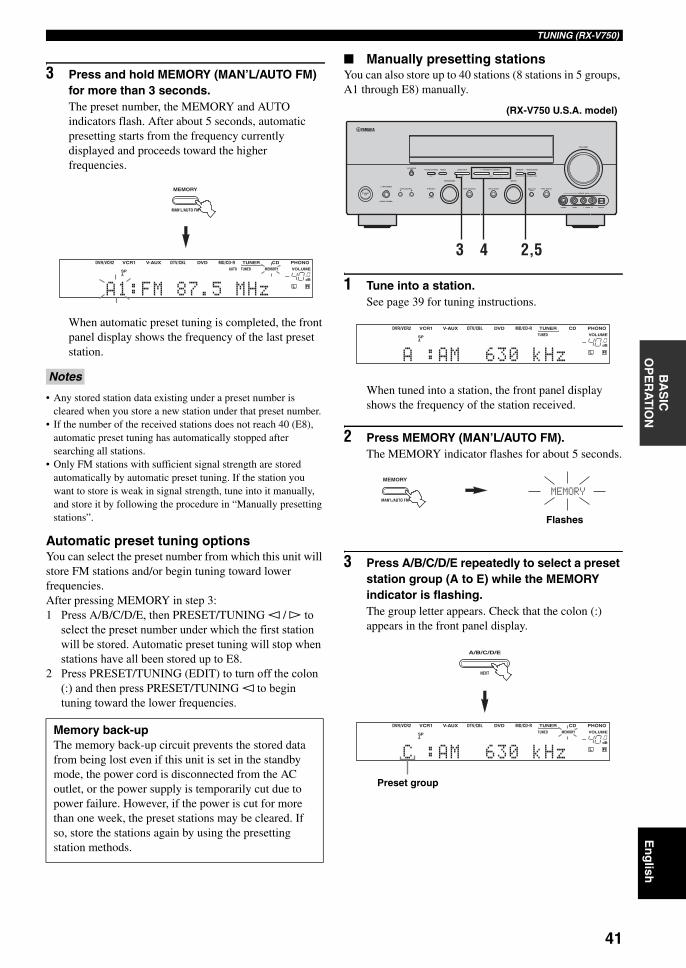
41
En
glish
TUNING (RX-V750)B
AS
IC
OP
ER
AT
ION
3 Press and hold MEMORY (MAN’L/AUTO FM) for more than 3 seconds.The preset number, the MEMORY and AUTO indicators flash. After about 5 seconds, automatic presetting starts from the frequency currently displayed and proceeds toward the higher frequencies.
When automatic preset tuning is completed, the front panel display shows the frequency of the last preset station.
• Any stored station data existing under a preset number is cleared when you store a new station under that preset number.
• If the number of the received stations does not reach 40 (E8), automatic preset tuning has automatically stopped after searching all stations.
• Only FM stations with sufficient signal strength are stored automatically by automatic preset tuning. If the station you want to store is weak in signal strength, tune into it manually, and store it by following the procedure in “Manually presetting stations”.
Automatic preset tuning optionsYou can select the preset number from which this unit will store FM stations and/or begin tuning toward lower frequencies.After pressing MEMORY in step 3:1 Press A/B/C/D/E, then PRESET/TUNING l / h to
select the preset number under which the first station will be stored. Automatic preset tuning will stop when stations have all been stored up to E8.
2 Press PRESET/TUNING (EDIT) to turn off the colon (:) and then press PRESET/TUNING l to begin tuning toward the lower frequencies.
Manually presetting stationsYou can also store up to 40 stations (8 stations in 5 groups, A1 through E8) manually.
1 Tune into a station.See page 39 for tuning instructions.
When tuned into a station, the front panel display shows the frequency of the station received.
2 Press MEMORY (MAN’L/AUTO FM).The MEMORY indicator flashes for about 5 seconds.
3 Press A/B/C/D/E repeatedly to select a preset station group (A to E) while the MEMORY indicator is flashing.The group letter appears. Check that the colon (:) appears in the front panel display.
Notes
Memory back-upThe memory back-up circuit prevents the stored data from being lost even if this unit is set in the standby mode, the power cord is disconnected from the AC outlet, or the power supply is temporarily cut due to power failure. However, if the power is cut for more than one week, the preset stations may be cleared. If so, store the stations again by using the presetting station methods.
MAN'L/AUTO FM
MEMORY
PHONOCDTUNERMD/CD-RDVD
HiFi DSP
DTV/CBLV-AUXVCR1DVR/VCR29624
q PLq EX
MATRIX DISCRETE SILENT CINEMA NIGHT ZONE2 PTY HOLD AUTO
PS RT CT EONPTY
TUNED STEREO MUTE VOLUMEMEMORY
SLEEPVIRTUAL
PCMq PL q PL x
A BSP
ftmSdB
dB96/24
LFEL C RSL SB SR
q DIGITAL
t
A1 1:FM187.5kMHz
AUTO/MAN'L MONO
S VIDEO VIDEO OPTICALL AUDIO R
MAN'L/AUTO FMLEVELNEXTEDIT
EFFECT
MEMORYFM/AMPRESET/TUNINGOPTIMIZER
MIC A/B/C/D/E
PROGRAM
l PRESET/TUNING h TUNING MODE
PURE DIRECTINPUT MODETONE CONTROLSTRAIGHTSPEAKERSPHONES
SILENT CINEMA
STANDBY/ON
BAMULTI CH
INPUT
VOLUME
VIDEO AUX
INPUT
43 2,5
(RX-V750 U.S.A. model)
PHONOCDTUNERMD/CD-RDVD
HiFi DSP
DTV/CBLV-AUXVCR1DVR/VCR29624
q PLq EX
MATRIX DISCRETE SILENT CINEMA NIGHT ZONE2 PTY HOLD AUTO
PS RT CT EONPTY
TUNED STEREO MUTE VOLUMEMEMORY
SLEEPVIRTUAL
PCMq PL q PL x
A BSP
ftmSdB
dB96/24
LFEL C RSL SB SR
q DIGITAL
t
A1 1:AM18630kkHz
MAN'L/AUTO FM
MEMORY
MEMORY
Flashes
NEXT
A/B/C/D/E
PHONOCDTUNERMD/CD-RDVD
HiFi DSP
DTV/CBLV-AUXVCR1DVR/VCR29624
q PLq EX
MATRIX DISCRETE SILENT CINEMA NIGHT ZONE2 PTY HOLD AUTO
PS RT CT EONPTY
TUNED STEREO MUTE VOLUMEMEMORY
SLEEPVIRTUAL
PCMq PL q PL x
A BSP
ftmSdB
dB96/24
LFEL C RSL SB SR
q DIGITAL
t
C1 1:AM18630kkHz
Preset group
01EN_00_RXV750_GB.book Page 41 Thursday, February 12, 2004 5:15 PM
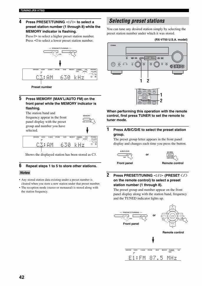
42
TUNING (RX-V750)
4 Press PRESET/TUNING l / h to select a preset station number (1 through 8) while the MEMORY indicator is flashing.Press h to select a higher preset station number.Press l to select a lower preset station number.
5 Press MEMORY (MAN’L/AUTO FM) on the front panel while the MEMORY indicator is flashing.The station band and frequency appear in the front panel display with the preset group and number you have selected.
6 Repeat steps 1 to 5 to store other stations.
• Any stored station data existing under a preset number is cleared when you store a new station under that preset number.
• The reception mode (stereo or monaural) is stored along with the station frequency.
You can tune any desired station simply by selecting the preset station number under which it was stored.
When performing this operation with the remote control, first press TUNER to set the remote to tuner mode.
1 Press A/B/C/D/E to select the preset station group.The preset group letter appears in the front panel display and changes each time you press the button.
2 Press PRESET/TUNING l / h (PRESET j / i on the remote control) to select a preset station number (1 through 8).The preset group and number appear on the front panel display along with the station band, frequency and the TUNED indicator lights up.
Notes
LEVEL
l PRESET/TUNING h
PHONOCDTUNERMD/CD-RDVD
HiFi DSP
DTV/CBLV-AUXVCR1DVR/VCR29624
q PLq EX
MATRIX DISCRETE SILENT CINEMA NIGHT ZONE2 PTY HOLD AUTO
PS RT CT EONPTY
TUNED STEREO MUTE VOLUMEMEMORY
SLEEPVIRTUAL
PCMq PL q PL x
A BSP
ftmSdB
dB96/24
LFEL C RSL SB SR
q DIGITAL
t
C1 3:AM18630kkHz
Preset number
MAN'L/AUTO FM
MEMORY
PHONOCDTUNERMD/CD-RDVD
HiFi DSP
DTV/CBLV-AUXVCR1DVR/VCR29624
q PLq EX
MATRIX DISCRETE SILENT CINEMA NIGHT ZONE2 PTY HOLD AUTO
PS RT CT EONPTY
TUNED STEREO MUTE VOLUMEMEMORY
SLEEPVIRTUAL
PCMq PL q PL x
A BSP
ftmSdB
dB96/24
LFEL C RSL SB SR
q DIGITAL
t
C1 3:AM18630kkHz
Shows the displayed station has been stored as C3.
Selecting preset stations
AUTO/MAN'L MONO
S VIDEO VIDEO OPTICALL AUDIO R
MAN'L/AUTO FMLEVELNEXTEDIT
EFFECT
MEMORYFM/AMPRESET/TUNINGOPTIMIZER
MIC A/B/C/D/E
PROGRAM
l PRESET/TUNING h TUNING MODE
PURE DIRECTINPUT MODETONE CONTROLSTRAIGHTSPEAKERSPHONES
SILENT CINEMA
STANDBY/ON
BAMULTI CH
INPUT
VOLUME
VIDEO AUX
INPUT
21
MUTE
MENUTITLE
CH CH
STARTSET MENULEVEL
A/B/C/D/ETV INPUT
MODE PTY SEEK
TV VOL
PRESET
TEST ON SCREEN STRAIGHT
EFFECT
DISPLAYRETURN
PRESET
TV MUTESELECT
TV VOL
12
(RX-V750 U.S.A. model)
NEXT
A/B/C/D/E
MENU
SET MENU
A/B/C/D/E
or
Front panel Remote control
LEVEL
l PRESET/TUNING h
CDTUNERMD/CD-RDVD
HiFi DSP
DTV/CBLV-AUXVCR1DVR/VCR2SILENT CINEMA NIGHT ZONE2 PTY HOLD AUTO
PS RT CT EONPTY
TUNED STEREO MMEMORY
SLEEPVIRTUAL
x
A BSP
ftmSdB
9
E1 1:FM187.5kMHz
or
Front panel
Remote control
TV VOL
PRESET PRESET
TV MUTE
TV VOL
SELECT
CHCH
+
+–
–
01EN_00_RXV750_GB.book Page 42 Thursday, February 12, 2004 5:15 PM
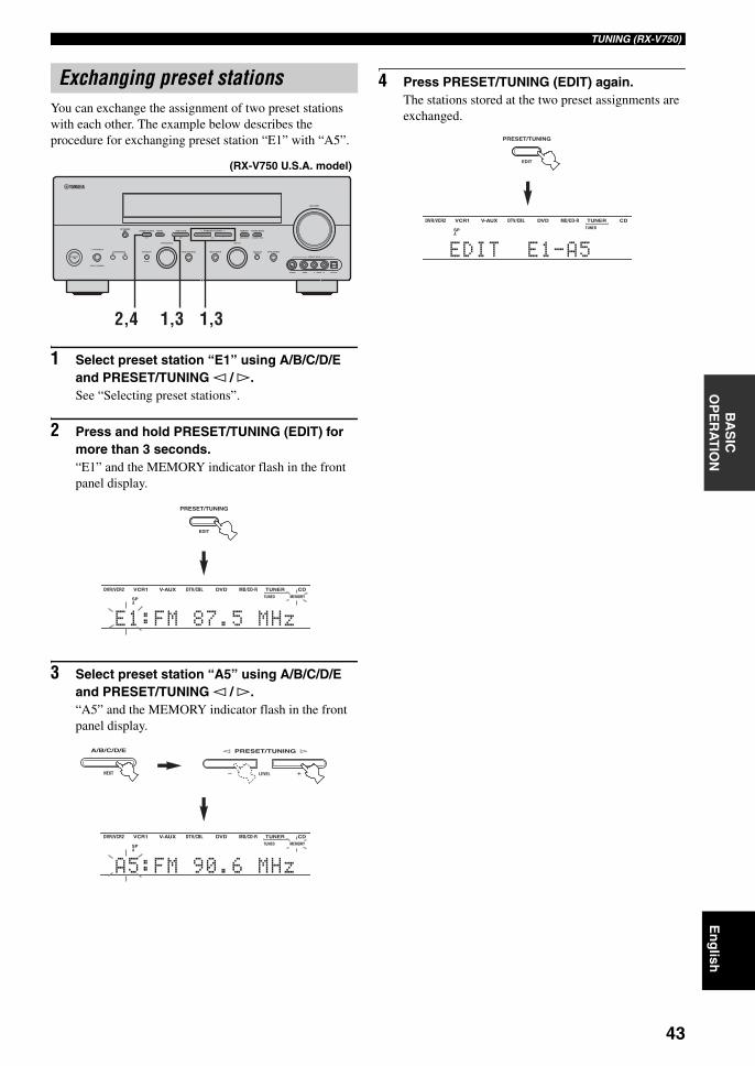
43
En
glish
TUNING (RX-V750)B
AS
IC
OP
ER
AT
ION
You can exchange the assignment of two preset stations with each other. The example below describes the procedure for exchanging preset station “E1” with “A5”.
1 Select preset station “E1” using A/B/C/D/E and PRESET/TUNING l / h.See “Selecting preset stations”.
2 Press and hold PRESET/TUNING (EDIT) for more than 3 seconds.“E1” and the MEMORY indicator flash in the front panel display.
3 Select preset station “A5” using A/B/C/D/E and PRESET/TUNING l / h.“A5” and the MEMORY indicator flash in the front panel display.
4 Press PRESET/TUNING (EDIT) again.The stations stored at the two preset assignments are exchanged.
Exchanging preset stations
AUTO/MAN'L MONO
S VIDEO VIDEO OPTICALL AUDIO R
MAN'L/AUTO FMLEVELNEXTEDIT
EFFECT
MEMORYFM/AMPRESET/TUNINGOPTIMIZER
MIC A/B/C/D/E
PROGRAM
l PRESET/TUNING h TUNING MODE
PURE DIRECTINPUT MODETONE CONTROLSTRAIGHTSPEAKERSPHONES
SILENT CINEMA
STANDBY/ON
BAMULTI CH
INPUT
VOLUME
VIDEO AUX
INPUT
2,4 1,31,3
(RX-V750 U.S.A. model)
EDIT
PRESET/TUNING
CDTUNERMD/CD-RDVD
HiFi DSP
DTV/CBLV-AUXVCR1DVR/VCR2SILENT CINEMA NIGHT ZONE2 PTY HOLD AUTO
PS RT CT EONPTY
TUNED STEREO MMEMORY
SLEEPVIRTUAL
x
A BSP
ftmSdB
9
E1 1:FM187.5kMHz
CDTUNERMD/CD-RDVD
HiFi DSP
DTV/CBLV-AUXVCR1DVR/VCR2SILENT CINEMA NIGHT ZONE2 PTY HOLD AUTO
PS RT CT EONPTY
TUNED STEREO MMEMORY
SLEEPVIRTUAL
x
A BSP
ftmSdB
9
A1 5:FM190.6kMHz
NEXT
A/B/C/D/E
LEVEL
l PRESET/TUNING h
CDTUNERMD/CD-RDVD
HiFi DSP
DTV/CBLV-AUXVCR1DVR/VCR2SILENT CINEMA NIGHT ZONE2 PTY HOLD AUTO
PS RT CT EONPTY
TUNED STEREO MMEMORY
SLEEPVIRTUAL
x
A BSP
ftmSdB
9
E1 EDIT18E1-A5Hz
EDIT
PRESET/TUNING
01EN_00_RXV750_GB.book Page 43 Thursday, February 12, 2004 5:15 PM
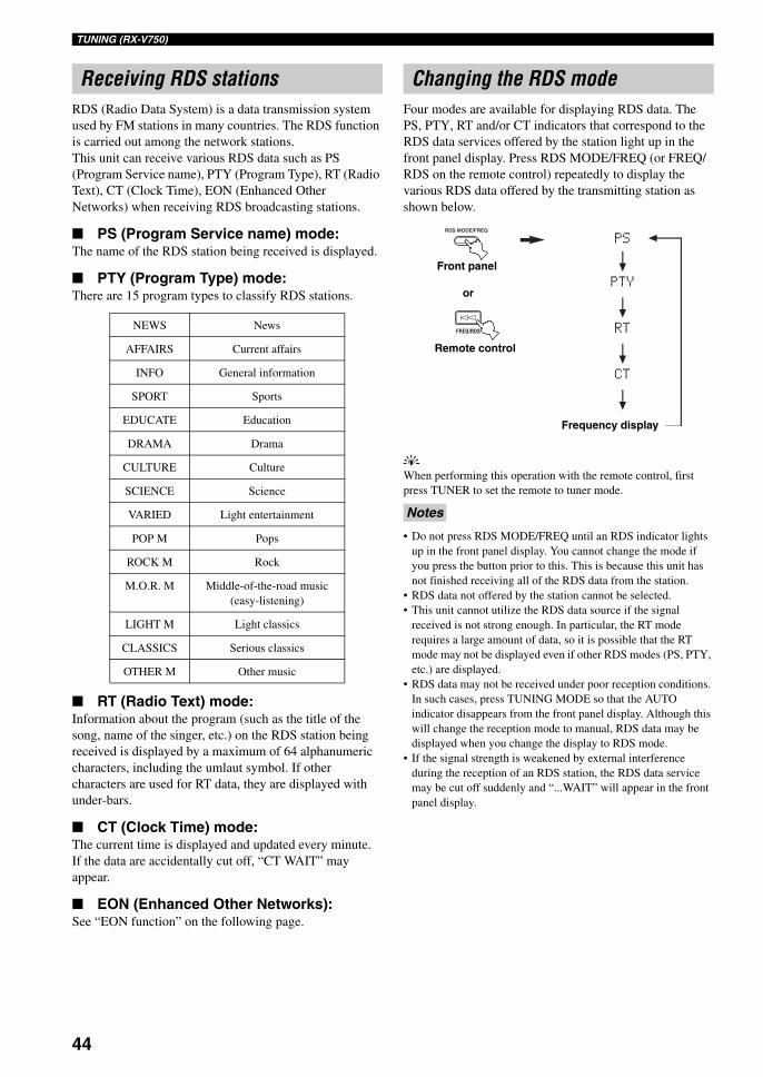
44
TUNING (RX-V750)
RDS (Radio Data System) is a data transmission system used by FM stations in many countries. The RDS function is carried out among the network stations.This unit can receive various RDS data such as PS (Program Service name), PTY (Program Type), RT (Radio Text), CT (Clock Time), EON (Enhanced Other Networks) when receiving RDS broadcasting stations.
PS (Program Service name) mode:The name of the RDS station being received is displayed.
PTY (Program Type) mode:There are 15 program types to classify RDS stations.
RT (Radio Text) mode:Information about the program (such as the title of the song, name of the singer, etc.) on the RDS station being received is displayed by a maximum of 64 alphanumeric characters, including the umlaut symbol. If other characters are used for RT data, they are displayed with under-bars.
CT (Clock Time) mode:The current time is displayed and updated every minute.If the data are accidentally cut off, “CT WAIT” may appear.
EON (Enhanced Other Networks):See “EON function” on the following page.
Four modes are available for displaying RDS data. The PS, PTY, RT and/or CT indicators that correspond to the RDS data services offered by the station light up in the front panel display. Press RDS MODE/FREQ (or FREQ/RDS on the remote control) repeatedly to display the various RDS data offered by the transmitting station as shown below.
yWhen performing this operation with the remote control, first press TUNER to set the remote to tuner mode.
• Do not press RDS MODE/FREQ until an RDS indicator lights up in the front panel display. You cannot change the mode if you press the button prior to this. This is because this unit has not finished receiving all of the RDS data from the station.
• RDS data not offered by the station cannot be selected.• This unit cannot utilize the RDS data source if the signal
received is not strong enough. In particular, the RT mode requires a large amount of data, so it is possible that the RT mode may not be displayed even if other RDS modes (PS, PTY, etc.) are displayed.
• RDS data may not be received under poor reception conditions. In such cases, press TUNING MODE so that the AUTO indicator disappears from the front panel display. Although this will change the reception mode to manual, RDS data may be displayed when you change the display to RDS mode.
• If the signal strength is weakened by external interference during the reception of an RDS station, the RDS data service may be cut off suddenly and “...WAIT” will appear in the front panel display.
Receiving RDS stations
NEWS News
AFFAIRS Current affairs
INFO General information
SPORT Sports
EDUCATE Education
DRAMA Drama
CULTURE Culture
SCIENCE Science
VARIED Light entertainment
POP M Pops
ROCK M Rock
M.O.R. M Middle-of-the-road music (easy-listening)
LIGHT M Light classics
CLASSICS Serious classics
OTHER M Other music
Changing the RDS mode
Notes
RDS MODE/FREQ
FREQ/RDS
PS
PTY
RT
CT
Frequency display
or
Front panel
Remote control
01EN_00_RXV750_GB.book Page 44 Thursday, February 12, 2004 5:15 PM
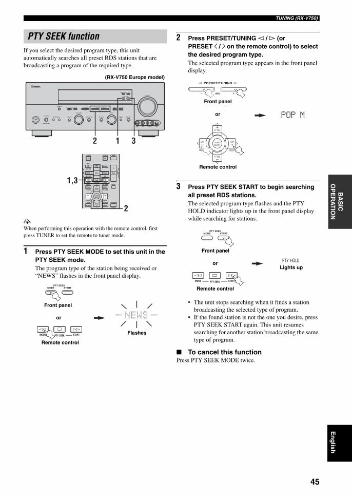
45
En
glish
TUNING (RX-V750)B
AS
IC
OP
ER
AT
ION
If you select the desired program type, this unit automatically searches all preset RDS stations that are broadcasting a program of the required type.
yWhen performing this operation with the remote control, first press TUNER to set the remote to tuner mode.
1 Press PTY SEEK MODE to set this unit in the PTY SEEK mode.The program type of the station being received or “NEWS” flashes in the front panel display.
2 Press PRESET/TUNING l / h (or PRESET j / i on the remote control) to select the desired program type.The selected program type appears in the front panel display.
3 Press PTY SEEK START to begin searching all preset RDS stations.The selected program type flashes and the PTY HOLD indicator lights up in the front panel display while searching for stations.
• The unit stops searching when it finds a station broadcasting the selected type of program.
• If the found station is not the one you desire, press PTY SEEK START again. This unit resumes searching for another station broadcasting the same type of program.
To cancel this functionPress PTY SEEK MODE twice.
PTY SEEK function
RDS MODE/FREQ EON
MODEPTY SEEK
START
AUTO/MAN'L MONO
S VIDEO VIDEO OPTICALL AUDIO R
MAN'L/AUTO FMLEVELNEXTEDIT
EFFECT
MEMORYFM/AMPRESET/TUNINGOPTIMIZER
MIC A/B/C/D/E
PROGRAM
l PRESET/TUNING h TUNING MODE
PURE DIRECTINPUT MODETONE CONTROLSTRAIGHTSPEAKERSPHONES
SILENT CINEMA
STANDBY/ON
BAMULTI CH
INPUT
VOLUME
VIDEO AUX
INPUT
2 1 3AMPPOWERPOWER
REC
AUDIO
MUTE
MENUTITLE
CH CH
VOL
DISC SKIP
FREQ/RDS EON
STARTSET MENULEVEL
A/B/C/D/ETV INPUT
MODE PTY SEEK
TV VOL
PRESET
TEST ON SCREEN STRAIGHT
EFFECT
DISPLAYRETURN
PRESET
TV MUTESELECT
TV VOL
AVTV
2
1,3
(RX-V750 Europe model)
MODEPTY SEEK
START
STARTMODE PTY SEEKFlashes
or
Front panel
Remote control
LEVEL
l PRESET/TUNING h
TV VOL
PRESET PRESET
TV MUTE
TV VOL
SELECT
CHCH
+
+–
–
POP M
Front panel
or
Remote control
PTY HOLD
MODEPTY SEEK
START
STARTMODE PTY SEEK
Lights upor
Front panel
Remote control
01EN_00_RXV750_GB.book Page 45 Thursday, February 12, 2004 5:15 PM
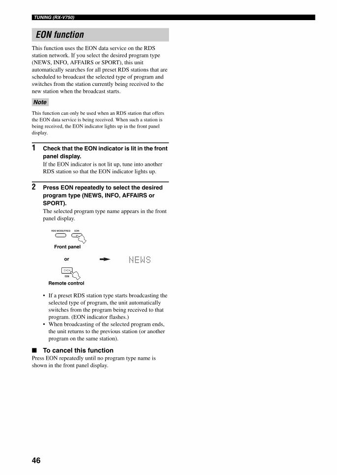
46
TUNING (RX-V750)
This function uses the EON data service on the RDS station network. If you select the desired program type (NEWS, INFO, AFFAIRS or SPORT), this unit automatically searches for all preset RDS stations that are scheduled to broadcast the selected type of program and switches from the station currently being received to the new station when the broadcast starts.
This function can only be used when an RDS station that offers the EON data service is being received. When such a station is being received, the EON indicator lights up in the front panel display.
1 Check that the EON indicator is lit in the front panel display.If the EON indicator is not lit up, tune into another RDS station so that the EON indicator lights up.
2 Press EON repeatedly to select the desired program type (NEWS, INFO, AFFAIRS or SPORT).The selected program type name appears in the front panel display.
• If a preset RDS station type starts broadcasting the selected type of program, the unit automatically switches from the program being received to that program. (EON indicator flashes.)
• When broadcasting of the selected program ends, the unit returns to the previous station (or another program on the same station).
To cancel this functionPress EON repeatedly until no program type name is shown in the front panel display.
EON function
Note
RDS MODE/FREQ EON
EON
or
Front panel
Remote control
01EN_00_RXV750_GB.book Page 46 Thursday, February 12, 2004 5:15 PM
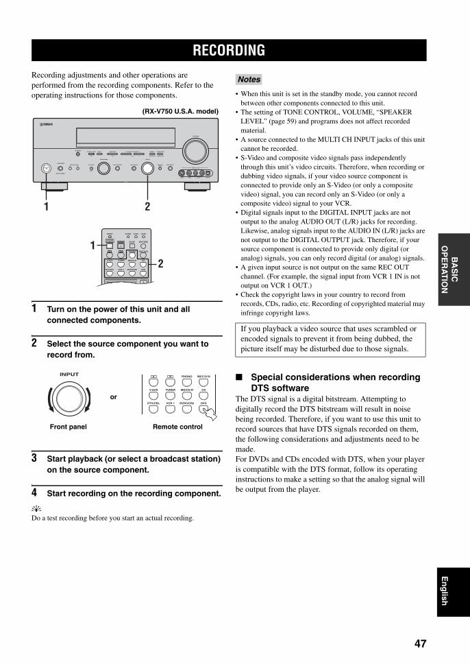
RECORDING
47
En
glish
BA
SIC
O
PE
RA
TIO
N
Recording adjustments and other operations are performed from the recording components. Refer to the operating instructions for those components.
1 Turn on the power of this unit and all connected components.
2 Select the source component you want to record from.
3 Start playback (or select a broadcast station) on the source component.
4 Start recording on the recording component.
yDo a test recording before you start an actual recording.
• When this unit is set in the standby mode, you cannot record between other components connected to this unit.
• The setting of TONE CONTROL, VOLUME, “SPEAKER LEVEL” (page 59) and programs does not affect recorded material.
• A source connected to the MULTI CH INPUT jacks of this unit cannot be recorded.
• S-Video and composite video signals pass independently through this unit’s video circuits. Therefore, when recording or dubbing video signals, if your video source component is connected to provide only an S-Video (or only a composite video) signal, you can record only an S-Video (or only a composite video) signal to your VCR.
• Digital signals input to the DIGITAL INPUT jacks are not output to the analog AUDIO OUT (L/R) jacks for recording. Likewise, analog signals input to the AUDIO IN (L/R) jacks are not output to the DIGITAL OUTPUT jack. Therefore, if your source component is connected to provide only digital (or analog) signals, you can only record digital (or analog) signals.
• A given input source is not output on the same REC OUT channel. (For example, the signal input from VCR 1 IN is not output on VCR 1 OUT.)
• Check the copyright laws in your country to record from records, CDs, radio, etc. Recording of copyrighted material may infringe copyright laws.
Special considerations when recording DTS software
The DTS signal is a digital bitstream. Attempting to digitally record the DTS bitstream will result in noise being recorded. Therefore, if you want to use this unit to record sources that have DTS signals recorded on them, the following considerations and adjustments need to be made.For DVDs and CDs encoded with DTS, when your player is compatible with the DTS format, follow its operating instructions to make a setting so that the analog signal will be output from the player.
RECORDING
AUTO/MAN'L MONO
S VIDEO VIDEO OPTICALL AUDIO R
MAN'L/AUTO FMLEVELNEXTEDIT
EFFECT
MEMORYFM/AMPRESET/TUNINGOPTIMIZER
MIC A/B/C/D/E
PROGRAM
l PRESET/TUNING h TUNING MODE
PURE DIRECTINPUT MODETONE CONTROLSTRAIGHTSPEAKERSPHONES
SILENT CINEMA
STANDBY/ON
BAMULTI CH
INPUT
VOLUME
VIDEO AUX
INPUT
1 2
TRANSMIT RE-NAME
INPUT MODESTANDBYSYSTEMPOWER
A B PHONO
CDMD/CD-RTUNERV-AUX
DVD
SELECT
VCR 1DTV/CBL DVR/VCR2
MULTI CH IN
SLEEP
CLEAR LEARN
1
2
(RX-V750 U.S.A. model)
INPUT A B PHONO
CDMD/CD-RTUNERV-AUX
DVDVCR 1DTV/CBL DVR/VCR2
MULTI CH IN
or
Front panel Remote control
Notes
If you playback a video source that uses scrambled or encoded signals to prevent it from being dubbed, the picture itself may be disturbed due to those signals.
01EN_00_RXV750_GB.book Page 47 Thursday, February 12, 2004 5:15 PM
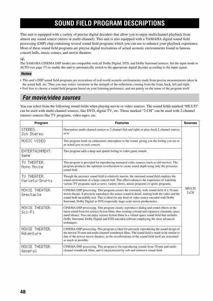
SOUND FIELD PROGRAM DESCRIPTIONS
48
This unit is equipped with a variety of precise digital decoders that allow you to enjoy multichannel playback from almost any sound source (stereo or multi-channel). This unit is also equipped with a YAMAHA digital sound field processing (DSP) chip containing several sound field programs which you can use to enhance your playback experience. Most of these sound field programs are precise digital recreations of actual acoustic environments found in famous concert halls, music venues, and movie theaters.
yThe YAMAHA CINEMA DSP modes are compatible with all Dolby Digital, DTS, and Dolby Surround sources. Set the input mode to AUTO (see page 37) to enable this unit to automatically switch to the appropriate digital decoder according to the input signal.
• This unit’s DSP sound field programs are recreations of real-world acoustic environments made from precise measurements taken in the actual hall, etc. Thus you may notice variations in the strength of the reflections coming from the front, back, left and right.
• Feel free to choose a sound field program based on your listening preference, and not purely on the name of the program itself.
You can select from the following sound fields when playing movie or video sources. The sound fields marked “MULTI” can be used with multi-channel sources, like DVD, digital TV, etc. Those marked “2-CH” can be used with 2-channel (stereo) sources like TV programs, video tapes, etc.
SOUND FIELD PROGRAM DESCRIPTIONS
Notes
For movie/video sources
Program Features Sources
STEREO:
2ch Stereo
Downmixes multi-channel sources to 2 channel (left and right) or plays back 2-channel sources as is.
MULTI2-CH
MUSIC VIDEO This program lends an enthusiastic atmosphere to the sound, giving you the feeling you are at an actual jazz or rock concert.
ENTERTAINMENT:
Game
This program adds a deep and spatial feeling to video game sounds.
TV THEATER:
Mono Movie
This program is provided for reproducing monaural video sources (such as old movies). The program produces the optimum reverberation to create sound depth using only the presernce sound field.
TV THEATER:
Variety/Sports
Though the presence sound field is relatively narrow, the surround sound field employs the sound environment of a large concert hall. This effect enhances the experience of watching various TV programs such as news, variety shows, music programs or sports programs.
MOVIE THEATER:
Spectacle
CINEMA DSP processing. This program creates the extremely wide sound field of a 70-mm movie theater. It precisely reproduces the source sound in detail, making both the video and the sound field incredibly real. This is ideal for any kind of video source encoded with Dolby Surround, Dolby Digital or DTS (especially large-scale movie productions).
MOVIE THEATER:
Sci-Fi
CINEMA DSP processing. This program clearly reproduces dialog and sound effects in the latest sound form for science fiction films, thus creating a broad and expansive cinematic space amid silence. You can enjoy science fiction films in a virtual-space sound field that includes Dolby Surround, Dolby Digital and DTS-encoded software employing the most advanced techniques.
MOVIE THEATER:
Adventure
CINEMA DSP processing. This program is ideal for precisely reproducing the sound design of the newest 70-mm and multi-channel soundtrack films. The sound field is made to be similar to that of the newest movie theaters, so the reverberations of the sound field itself are restrained as much as possible.
MOVIE THEATER:
General
CINEMA DSP processing. This program is for reproducing sounds from 70-mm and multi-channel soundtrack films, and is characterized by soft and extensive sound field.
01EN_00_RXV750_GB.book Page 48 Thursday, February 12, 2004 5:15 PM
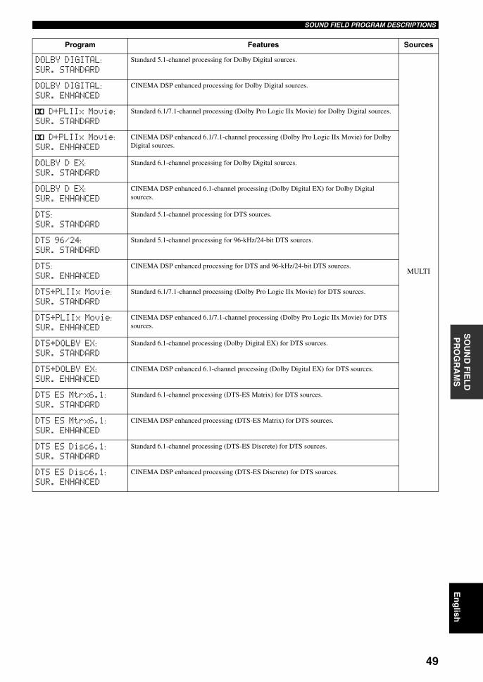
49
En
glish
SOUND FIELD PROGRAM DESCRIPTIONSS
OU
ND
FIE
LD
P
RO
GR
AM
S
DOLBY DIGITAL:
SUR. STANDARD
Standard 5.1-channel processing for Dolby Digital sources.
MULTI
DOLBY DIGITAL:
SUR. ENHANCED
CINEMA DSP enhanced processing for Dolby Digital sources.
q D+PLIIx Movie:
SUR. STANDARD
Standard 6.1/7.1-channel processing (Dolby Pro Logic IIx Movie) for Dolby Digital sources.
q D+PLIIx Movie:
SUR. ENHANCED
CINEMA DSP enhanced 6.1/7.1-channel processing (Dolby Pro Logic IIx Movie) for Dolby Digital sources.
DOLBY D EX:
SUR. STANDARD
Standard 6.1-channel processing for Dolby Digital sources.
DOLBY D EX:
SUR. ENHANCED
CINEMA DSP enhanced 6.1-channel processing (Dolby Digital EX) for Dolby Digital sources.
DTS:
SUR. STANDARD
Standard 5.1-channel processing for DTS sources.
DTS 96/24:
SUR. STANDARD
Standard 5.1-channel processing for 96-kHz/24-bit DTS sources.
DTS:
SUR. ENHANCED
CINEMA DSP enhanced processing for DTS and 96-kHz/24-bit DTS sources.
DTS+PLIIx Movie:
SUR. STANDARD
Standard 6.1/7.1-channel processing (Dolby Pro Logic IIx Movie) for DTS sources.
DTS+PLIIx Movie:
SUR. ENHANCED
CINEMA DSP enhanced 6.1/7.1-channel processing (Dolby Pro Logic IIx Movie) for DTS sources.
DTS+DOLBY EX:
SUR. STANDARD
Standard 6.1-channel processing (Dolby Digital EX) for DTS sources.
DTS+DOLBY EX:
SUR. ENHANCED
CINEMA DSP enhanced 6.1-channel processing (Dolby Digital EX) for DTS sources.
DTS ES Mtrx6.1:
SUR. STANDARD
Standard 6.1-channel processing (DTS-ES Matrix) for DTS sources.
DTS ES Mtrx6.1:
SUR. ENHANCED
CINEMA DSP enhanced processing (DTS-ES Matrix) for DTS sources.
DTS ES Disc6.1:
SUR. STANDARD
Standard 6.1-channel processing (DTS-ES Discrete) for DTS sources.
DTS ES Disc6.1:
SUR. ENHANCED
CINEMA DSP enhanced processing (DTS-ES Discrete) for DTS sources.
Program Features Sources
01EN_00_RXV750_GB.book Page 49 Thursday, February 12, 2004 5:15 PM
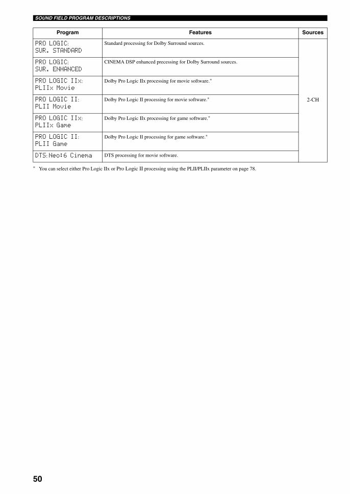
50
SOUND FIELD PROGRAM DESCRIPTIONS
* You can select either Pro Logic IIx or Pro Logic II processing using the PLII/PLIIx parameter on page 78.
PRO LOGIC:
SUR. STANDARD
Standard processing for Dolby Surround sources.
2-CH
PRO LOGIC:
SUR. ENHANCED
CINEMA DSP enhanced precessing for Dolby Surround sources.
PRO LOGIC IIx:
PLIIx MovieDolby Pro Logic IIx processing for movie software.*
PRO LOGIC II:
PLII MovieDolby Pro Logic II processing for movie software.*
PRO LOGIC IIx:
PLIIx GameDolby Pro Logic IIx processing for game software.*
PRO LOGIC II:
PLII GameDolby Pro Logic II processing for game software.*
DTS: Neo:6 Cinema DTS processing for movie software.
Program Features Sources
01EN_00_RXV750_GB.book Page 50 Thursday, February 12, 2004 5:15 PM
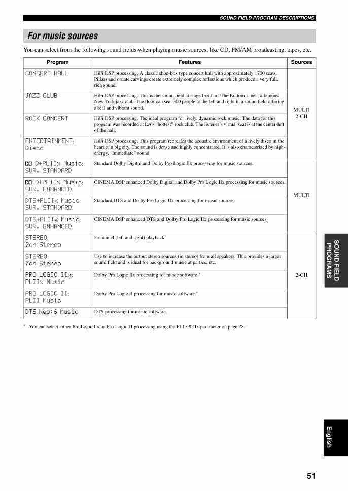
51
En
glish
SOUND FIELD PROGRAM DESCRIPTIONSS
OU
ND
FIE
LD
P
RO
GR
AM
S
You can select from the following sound fields when playing music sources, like CD, FM/AM broadcasting, tapes, etc.
* You can select either Pro Logic IIx or Pro Logic II processing using the PLII/PLIIx parameter on page 78.
For music sources
Program Features Sources
CONCERT HALL HiFi DSP processing. A classic shoe-box type concert hall with approximately 1700 seats. Pillars and ornate carvings create extremely complex reflections which produce a very full, rich sound.
MULTI2-CH
JAZZ CLUB HiFi DSP processing. This is the sound field at stage front in “The Bottom Line”, a famous New York jazz club. The floor can seat 300 people to the left and right in a sound field offering a real and vibrant sound.
ROCK CONCERT HiFi DSP processing. The ideal program for lively, dynamic rock music. The data for this program was recorded at LA’s “hottest” rock club. The listener’s virtual seat is at the center-left of the hall.
ENTERTAINMENT:
Disco
HiFi DSP processing. This program recreates the acoustic environment of a lively disco in the heart of a big city. The sound is dense and highly concentrated. It is also characterized by high-energy, “immediate” sound.
q D+PLIIx Music:
SUR. STANDARD
Standard Dolby Digital and Dolby Pro Logic IIx processing for music sources.
MULTI
q D+PLIIx Music:
SUR. ENHANCED
CINEMA DSP enhanced Dolby Digital and Dolby Pro Logic IIx processing for music sources.
DTS+PLIIx Music:
SUR. STANDARD
Standard DTS and Dolby Pro Logic IIx processing for music sources.
DTS+PLIIx Music:
SUR. ENHANCED
CINEMA DSP enhanced DTS and Dolby Pro Logic IIx processing for music sources.
STEREO:
2ch Stereo
2-channel (left and right) playback.
2-CH
STEREO:
7ch Stereo
Use to increase the output stereo sources (in stereo) from all speakers. This provides a larger sound field and is ideal for background music at parties, etc.
PRO LOGIC IIx:
PLIIx MusicDolby Pro Logic IIx processing for music software.*
PRO LOGIC II:
PLII MusicDolby Pro Logic II processing for music software.*
DTS: Neo:6 Music DTS processing for music software.
01EN_00_RXV750_GB.book Page 51 Thursday, February 12, 2004 5:15 PM
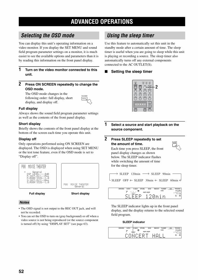
ADVANCED OPERATIONS
52
You can display this unit’s operating information on a video monitor. If you display the SET MENU and sound field program parameter settings on a monitor, it is much easier to see the available options and parameters than it is by reading this information on the front panel display.
1 Turn on the video monitor connected to this unit.
2 Press ON SCREEN repeatedly to change the OSD mode.The OSD mode changes in the following order: full display, short display, and display off.
Full displayAlways shows the sound field program parameter settings as well as the contents of the front panel display.
Short displayBriefly shows the contents of the front panel display at the bottom of the screen each time you operate this unit.
Display offOnly operations performed using ON SCREEN are displayed. The OSD is displayed when using SET MENU or the test tone feature, even if the OSD mode is set to “Display off”.
• The OSD signal is not output to the REC OUT jack, and will not be recorded.
• You can set the OSD to turn on (gray background) or off when a video source is not being reproduced (or the source component is turned off) by using “DISPLAY SET” (see page 63).
Use this feature to automatically set this unit in the standby mode after a certain amount of time. The sleep timer is useful when you are going to sleep while this unit is playing or recording a source. The sleep timer also automatically turns off any external components connected to the AC OUTLET(S).
Setting the sleep timer
1 Select a source and start playback on the source component.
2 Press SLEEP repeatedly to set the amount of time.Each time you press SLEEP, the front panel display changes as shown below. The SLEEP indicator flashes while switching the amount of time for the sleep timer.
The SLEEP indicator lights up in the front panel display, and the display returns to the selected sound field program.
ADVANCED OPERATIONS
Selecting the OSD mode
Notes
ON SCREEN
DISPLAY
P08 MOVIE THEATER
.GeneralDSPLEVEL;;;;0dBP.INIT.DLY;;15msP.ROOMSIZE;;1.0S.INIT.DLY;;20msS.ROOMSIZE;;1.0
P08MOVIETHEATERGeneral
Full display Short display
Using the sleep timer
TRANSMIT RE-NAME
INPUT MODESTANDBYSYSTEMPOWER
A B PHONO
CDMD/CD-RTUNERV-AUX
DVD
AMPPOWERPOWER
AVTV
SELECT
VCR 1DTV/CBL DVR/VCR2
MULTI CH IN
SLEEP
CLEAR LEARN
2
SLEEP
SLEEP 90min
SLEEP 60minSLEEP 30minSLEEP OFF
SLEEP 120min
PHONOCDTUNERMD/CD-RDVD
HiFi DSP
DTV/CBLV-AUXVCR1DVR/VCR29624
q PLq EX
MATRIX DISCRETE SILENT CINEMA NIGHT ZONE2 PTY HOLD AUTO
PS RT CT EONPTY
TUNED STEREO MUTE VOLUMEMEMORY
SLEEPVIRTUAL
PCMq PL q PL x
A BSP
ftmSdB
dB96/24
LFEL C RSL SB SR
q DIGITAL
t
E1 SLEEP8120minz
PHONOCDTUNERMD/CD-RDVD
HiFi DSP
DTV/CBLV-AUXVCR1DVR/VCR29624
q PLq EX
MATRIX DISCRETE SILENT CINEMA NIGHT ZONE2 PTY HOLD AUTO
PS RT CT EONPTY
TUNED STEREO MUTE VOLUMEMEMORY
SLEEPVIRTUAL
PCMq PL q PL x
A BSP
ftmSdB
dB96/24
LFEL C RSL SB SR
q DIGITAL
t
E1 CONCERT2HALLz
SLEEP indicator
01EN_00_RXV750_GB.book Page 52 Thursday, February 12, 2004 5:15 PM
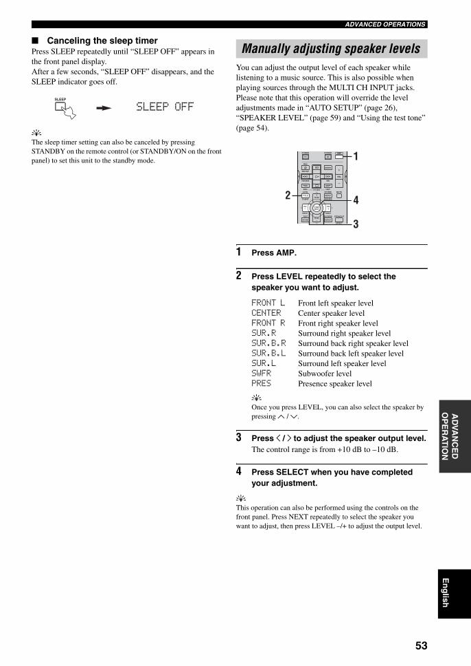
53
En
glish
ADVANCED OPERATIONSA
DVA
NC
ED
O
PE
RA
TIO
N
Canceling the sleep timerPress SLEEP repeatedly until “SLEEP OFF” appears in the front panel display.After a few seconds, “SLEEP OFF” disappears, and the SLEEP indicator goes off.
yThe sleep timer setting can also be canceled by pressing STANDBY on the remote control (or STANDBY/ON on the front panel) to set this unit to the standby mode.
You can adjust the output level of each speaker while listening to a music source. This is also possible when playing sources through the MULTI CH INPUT jacks.Please note that this operation will override the level adjustments made in “AUTO SETUP” (page 26), “SPEAKER LEVEL” (page 59) and “Using the test tone” (page 54).
1 Press AMP.
2 Press LEVEL repeatedly to select the speaker you want to adjust.
FRONT L Front left speaker levelCENTER Center speaker levelFRONT R Front right speaker levelSUR.R Surround right speaker levelSUR.B.R Surround back right speaker levelSUR.B.L Surround back left speaker levelSUR.L Surround left speaker levelSWFR Subwoofer levelPRES Presence speaker level
yOnce you press LEVEL, you can also select the speaker by pressing u / d.
3 Press j / i to adjust the speaker output level.The control range is from +10 dB to –10 dB.
4 Press SELECT when you have completed your adjustment.
yThis operation can also be performed using the controls on the front panel. Press NEXT repeatedly to select the speaker you want to adjust, then press LEVEL –/+ to adjust the output level.
SLEEP
SLEEP OFF
Manually adjusting speaker levels
AMPPOWERPOWER
REC
AUDIO
MUTE
MENUTITLE
CH CH
VOL
DISC SKIP
FREQ/RDS EON
STARTSET MENULEVEL
A/B/C/D/ETV INPUT
MODE PTY SEEK
TV VOL
PRESET
TEST ON SCREEN STRAIGHT
EFFECT
DISPLAYRETURN
PRESET
TV MUTESELECT
TV VOL
AVTV 1
3
2 4
01EN_00_RXV750_GB.book Page 53 Thursday, February 12, 2004 5:15 PM
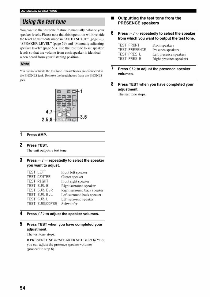
54
ADVANCED OPERATIONS
You can use the test tone feature to manually balance your speaker levels. Please note that this operation will override the level adjustments made in “AUTO SETUP” (page 26), “SPEAKER LEVEL” (page 59) and “Manually adjusting speaker levels” (page 53). Use the test tone to set speaker levels so that the volume from each speaker is identical when heard from your listening position.
You cannot activate the test tone if headphones are connected to the PHONES jack. Remove the headphones from the PHONES jack.
1 Press AMP.
2 Press TEST.The unit outputs a test tone.
3 Press u / d repeatedly to select the speaker you want to adjust.
TEST LEFT Front left speakerTEST CENTER Center speakerTEST RIGHT Front right speakerTEST SUR.R Right surround speakerTEST SUR.B.R Right surround back speakerTEST SUR.B.L Left surround back speakerTEST SUR.L Left surround speakerTEST SUBWOOFER Subwoofer
4 Press j / i to adjust the speaker volumes.
5 Press TEST when you have completed your adjustment.The test tone stops.
If PRESENCE SP in “SPEAKER SET” is set to YES, you can adjust the presence speaker volumes (proceed to step 6).
Outputting the test tone from the PRESENCE speakers
6 Press u / d repeatedly to select the speaker from which you want to output the test tone.
TEST FRONT Front speakersTEST PRESENCE Presence speakersTEST PRES L Left presence speakersTEST PRES R Right presence speakers
7 Press j / i to adjust the presence speaker volumes.
8 Press TEST when you have completed your adjustment.The test tone stops.
Using the test tone
Note
AMPPOWERPOWER
REC
AUDIO
MUTE
MENUTITLE
CH CH
VOL
DISC SKIP
FREQ/RDS EON
STARTSET MENULEVEL
A/B/C/D/ETV INPUT
MODE PTY SEEK
TV VOL
PRESET
TEST ON SCREEN STRAIGHT
EFFECT
DISPLAYRETURN
PRESET
TV MUTESELECT
TV VOL
AVTV 1
3,62,5,8
4,7
01EN_00_RXV750_GB.book Page 54 Thursday, February 12, 2004 5:15 PM
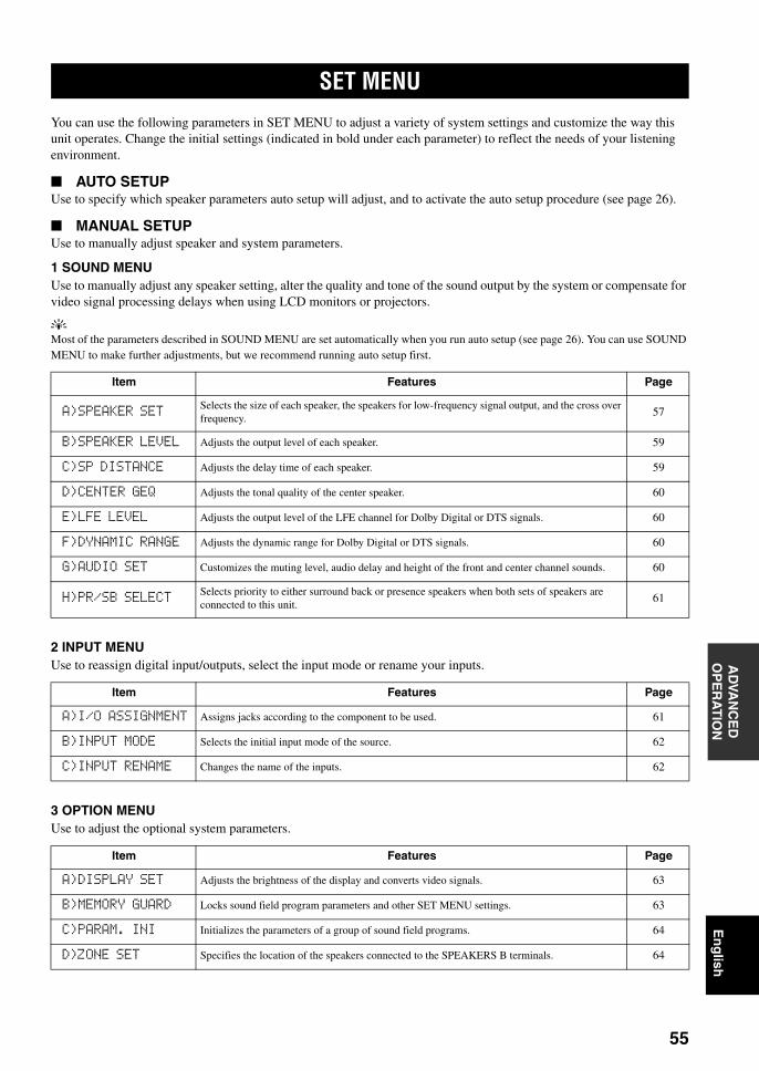
SET MENU
55
En
glish
AD
VAN
CE
D
OP
ER
AT
ION
You can use the following parameters in SET MENU to adjust a variety of system settings and customize the way this unit operates. Change the initial settings (indicated in bold under each parameter) to reflect the needs of your listening environment.
AUTO SETUPUse to specify which speaker parameters auto setup will adjust, and to activate the auto setup procedure (see page 26).
MANUAL SETUPUse to manually adjust speaker and system parameters.
1 SOUND MENUUse to manually adjust any speaker setting, alter the quality and tone of the sound output by the system or compensate for video signal processing delays when using LCD monitors or projectors.
yMost of the parameters described in SOUND MENU are set automatically when you run auto setup (see page 26). You can use SOUND MENU to make further adjustments, but we recommend running auto setup first.
2 INPUT MENUUse to reassign digital input/outputs, select the input mode or rename your inputs.
3 OPTION MENUUse to adjust the optional system parameters.
SET MENU
Item Features Page
A)SPEAKER SETSelects the size of each speaker, the speakers for low-frequency signal output, and the cross over frequency.
57
B)SPEAKER LEVEL Adjusts the output level of each speaker. 59
C)SP DISTANCE Adjusts the delay time of each speaker. 59
D)CENTER GEQ Adjusts the tonal quality of the center speaker. 60
E)LFE LEVEL Adjusts the output level of the LFE channel for Dolby Digital or DTS signals. 60
F)DYNAMIC RANGE Adjusts the dynamic range for Dolby Digital or DTS signals. 60
G)AUDIO SET Customizes the muting level, audio delay and height of the front and center channel sounds. 60
H)PR/SB SELECTSelects priority to either surround back or presence speakers when both sets of speakers are connected to this unit.
61
Item Features Page
A)I/O ASSIGNMENT Assigns jacks according to the component to be used. 61
B)INPUT MODE Selects the initial input mode of the source. 62
C)INPUT RENAME Changes the name of the inputs. 62
Item Features Page
A)DISPLAY SET Adjusts the brightness of the display and converts video signals. 63
B)MEMORY GUARD Locks sound field program parameters and other SET MENU settings. 63
C)PARAM. INI Initializes the parameters of a group of sound field programs. 64
D)ZONE SET Specifies the location of the speakers connected to the SPEAKERS B terminals. 64
01EN_00_RXV750_GB.book Page 55 Thursday, February 12, 2004 5:15 PM
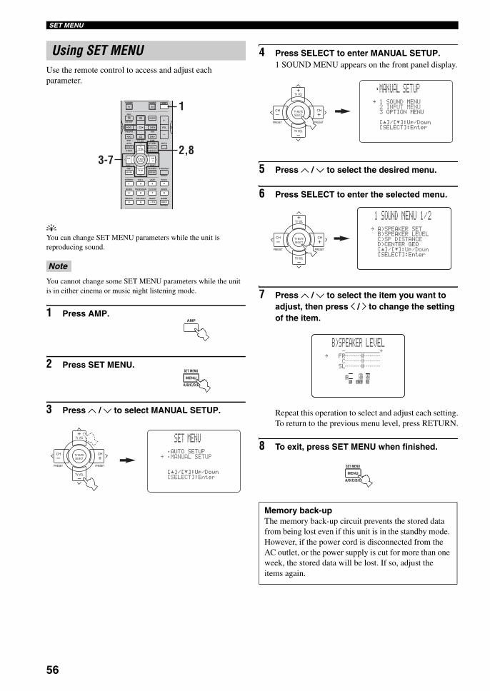
56
SET MENU
Use the remote control to access and adjust each parameter.
yYou can change SET MENU parameters while the unit is reproducing sound.
You cannot change some SET MENU parameters while the unit is in either cinema or music night listening mode.
1 Press AMP.
2 Press SET MENU.
3 Press u / d to select MANUAL SETUP.
4 Press SELECT to enter MANUAL SETUP.1 SOUND MENU appears on the front panel display.
5 Press u / d to select the desired menu.
6 Press SELECT to enter the selected menu.
7 Press u / d to select the item you want to adjust, then press j / i to change the setting of the item.
Repeat this operation to select and adjust each setting.To return to the previous menu level, press RETURN.
8 To exit, press SET MENU when finished.
Using SET MENU
Note
AMPPOWERPOWER
REC
AUDIO
MUTE
MENUTITLE
CH CH
VOL
DISC SKIP
FREQ/RDS EON
STARTSET MENULEVEL
A/B/C/D/ETV INPUT
MODE PTY SEEK
TV VOL
PRESET
TEST ON SCREEN STRAIGHT
ROCKJAZZHALLSTEREO
4321
8
10
7
09
65
ENTER
MOVIETV THTRMUSIC ENTERTAIN
EX/ESNIGHTq/DTS PURE DIRECT
EFFECT
CHP/INDEX
DISPLAYRETURN
PRESET
TV MUTESELECT
TV VOL
AVTV 1
2,83-7
AMP
MENU
SET MENU
A/B/C/D/E
TV VOL
PRESET PRESET
TV MUTE
TV VOL
SELECT
CHCH
+
+–
–
SET MENU
;AUTOSETUP.;MANUALSETUP
[]/[]:Up/Down[SELECT]:Enter
p
p
Memory back-upThe memory back-up circuit prevents the stored data from being lost even if this unit is in the standby mode. However, if the power cord is disconnected from the AC outlet, or the power supply is cut for more than one week, the stored data will be lost. If so, adjust the items again.
TV VOL
PRESET PRESET
TV MUTE
TV VOL
SELECT
CHCH
+
+–
–
;MANUAL SETUP
.1SOUNDMENU2INPUTMENU3OPTIONMENU
[]/[]:Up/Down[SELECT]:Enter
p
p
TV VOL
PRESET PRESET
TV MUTE
TV VOL
SELECT
CHCH
+
+–
–
.A)SPEAKERSETB)SPEAKERLEVELC)SPDISTANCED)CENTERGEQ[]/[]:Up/Down[SELECT]:Enter
p
p
1 SOUND MENU 1/2
-+.FRCSL
B)SPEAKER LEVEL
MENU
SET MENU
A/B/C/D/E
01EN_00_RXV750_GB.book Page 56 Thursday, February 12, 2004 5:15 PM
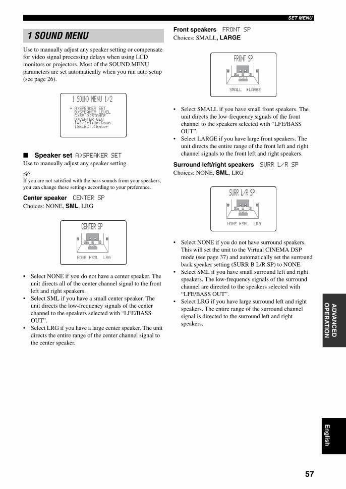
57
En
glish
SET MENUA
DVA
NC
ED
O
PE
RA
TIO
N
Use to manually adjust any speaker setting or compensate for video signal processing delays when using LCD monitors or projectors. Most of the SOUND MENU parameters are set automatically when you run auto setup (see page 26).
Speaker set A)SPEAKER SETUse to manually adjust any speaker setting.
yIf you are not satisfied with the bass sounds from your speakers, you can change these settings according to your preference.
Center speaker CENTER SPChoices: NONE, SML, LRG
• Select NONE if you do not have a center speaker. The unit directs all of the center channel signal to the front left and right speakers.
• Select SML if you have a small center speaker. The unit directs the low-frequency signals of the center channel to the speakers selected with “LFE/BASS OUT”.
• Select LRG if you have a large center speaker. The unit directs the entire range of the center channel signal to the center speaker.
Front speakers FRONT SPChoices: SMALL, LARGE
• Select SMALL if you have small front speakers. The unit directs the low-frequency signals of the front channel to the speakers selected with “LFE/BASS OUT”.
• Select LARGE if you have large front speakers. The unit directs the entire range of the front left and right channel signals to the front left and right speakers.
Surround left/right speakers SURR L/R SPChoices: NONE, SML, LRG
• Select NONE if you do not have surround speakers. This will set the unit to the Virtual CINEMA DSP mode (see page 37) and automatically set the surround back speaker setting (SURR B L/R SP) to NONE.
• Select SML if you have small surround left and right speakers. The low-frequency signals of the surround channel are directed to the speakers selected with “LFE/BASS OUT”.
• Select LRG if you have large surround left and right speakers. The entire range of the surround channel signal is directed to the surround left and right speakers.
1 SOUND MENU
.A)SPEAKERSETB)SPEAKERLEVELC)SPDISTANCED)CENTERGEQ[]/[]:Up/Down[SELECT]:Enter
p
p
1 SOUND MENU 1/2
NONE)SMLLRG
CENTER SP
SMALL)LARGE
FRONT SP
NONE)SMLLRG
SURR L/R SP
01EN_00_RXV750_GB.book Page 57 Thursday, February 12, 2004 5:15 PM
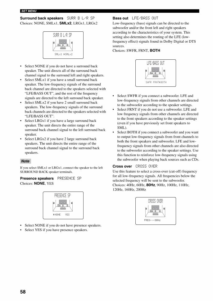
58
SET MENU
Surround back speakers SURR B L/R SPChoices: NONE, SMLx1, SMLx2, LRGx1, LRGx2
• Select NONE if you do not have a surround back speaker. The unit directs all of the surround back channel signal to the surround left and right speakers.
• Select SMLx1 if you have a small surround back speaker. The low-frequency signals of the surround back channel are directed to the speakers selected with “LFE/BASS OUT”, and the rest of the frequency signals are directed to the left surround back speaker.
• Select SMLx2 if you have 2 small surround back speakers. The low-frequency signals of the surround back channels are directed to the speakers selected with “LFE/BASS OUT”.
• Select LRGx1 if you have a large surround back speaker. The unit directs the entire range of the surround back channel signal to the left surround back speaker.
• Select LRGx2 if you have 2 large surround back speakers. The unit directs the entire range of the surround back channel signal to the surround back speakers.
If you select SMLx1 or LRGx1, connect the speaker to the left SURROUND BACK speaker terminals.
Presence speakers PRESENCE SPChoices: NONE, YES
• Select NONE if you do not have presence speakers.• Select YES if you have presence speakers.
Bass out LFE/BASS OUTLow-frequency (bass) signals can be directed to the subwoofer and/or the front left and right speakers according to the characteristics of your system. This setting also determines the routing of the LFE (low-frequency effect) signals found in Dolby Digital or DTS sources.Choices: SWFR, FRNT, BOTH
• Select SWFR if you connect a subwoofer. LFE and low-frequency signals from other channels are directed to the subwoofer according to the speaker settings.
• Select FRNT if you do not use a subwoofer. LFE and low frequency signals from other channels are directed to the front speakers according to the speaker settings (even if you have previously set front speakers to SML).
• Select BOTH if you connect a subwoofer and you want to output low-frequency signals from front channels to both the front speakers and subwoofer. LFE and low-frequency signals from other channels are also directed to the subwoofer according to the speaker settings. Use this function to reinforce low-frequency signals using the subwoofer when playing back sources such as CDs.
Cross over CROSS OVERUse this feature to select a cross-over (cut-off) frequency for all low-frequency signals. All frequencies below the selected frequency will be sent to the subwoofer.Choices: 40Hz, 60Hz, 80Hz, 90Hz, 100Hz, 110Hz, 120Hz, 160Hz, 200Hz
Note
SMLx1)SMLx2
SURR B L/R SP
)NONEYES
PRESENCE SP
SWFRFRNT)BOTH
LFE/BASS OUT
FREQ;;;80Hz
CROSS OVER
01EN_00_RXV750_GB.book Page 58 Thursday, February 12, 2004 5:15 PM
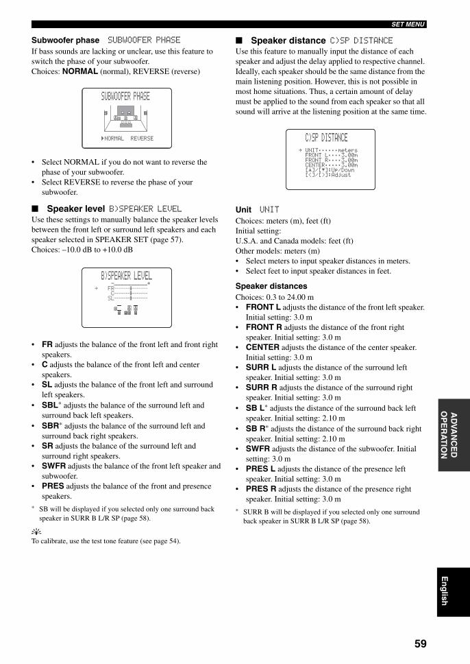
59
En
glish
SET MENUA
DVA
NC
ED
O
PE
RA
TIO
N
Subwoofer phase SUBWOOFER PHASEIf bass sounds are lacking or unclear, use this feature to switch the phase of your subwoofer.Choices: NORMAL (normal), REVERSE (reverse)
• Select NORMAL if you do not want to reverse the phase of your subwoofer.
• Select REVERSE to reverse the phase of your subwoofer.
Speaker level B)SPEAKER LEVELUse these settings to manually balance the speaker levels between the front left or surround left speakers and each speaker selected in SPEAKER SET (page 57).Choices: –10.0 dB to +10.0 dB
• FR adjusts the balance of the front left and front right speakers.
• C adjusts the balance of the front left and center speakers.
• SL adjusts the balance of the front left and surround left speakers.
• SBL* adjusts the balance of the surround left and surround back left speakers.
• SBR* adjusts the balance of the surround left and surround back right speakers.
• SR adjusts the balance of the surround left and surround right speakers.
• SWFR adjusts the balance of the front left speaker and subwoofer.
• PRES adjusts the balance of the front and presence speakers.
* SB will be displayed if you selected only one surround back speaker in SURR B L/R SP (page 58).
yTo calibrate, use the test tone feature (see page 54).
Speaker distance C)SP DISTANCEUse this feature to manually input the distance of each speaker and adjust the delay applied to respective channel. Ideally, each speaker should be the same distance from the main listening position. However, this is not possible in most home situations. Thus, a certain amount of delay must be applied to the sound from each speaker so that all sound will arrive at the listening position at the same time.
Unit UNITChoices: meters (m), feet (ft)Initial setting:U.S.A. and Canada models: feet (ft) Other models: meters (m)• Select meters to input speaker distances in meters.• Select feet to input speaker distances in feet.
Speaker distancesChoices: 0.3 to 24.00 m• FRONT L adjusts the distance of the front left speaker.
Initial setting: 3.0 m• FRONT R adjusts the distance of the front right
speaker. Initial setting: 3.0 m• CENTER adjusts the distance of the center speaker.
Initial setting: 3.0 m• SURR L adjusts the distance of the surround left
speaker. Initial setting: 3.0 m• SURR R adjusts the distance of the surround right
speaker. Initial setting: 3.0 m• SB L* adjusts the distance of the surround back left
speaker. Initial setting: 2.10 m• SB R* adjusts the distance of the surround back right
speaker. Initial setting: 2.10 m• SWFR adjusts the distance of the subwoofer. Initial
setting: 3.0 m• PRES L adjusts the distance of the presence left
speaker. Initial setting: 3.0 m• PRES R adjusts the distance of the presence right
speaker. Initial setting: 3.0 m* SURR B will be displayed if you selected only one surround
back speaker in SURR B L/R SP (page 58).
)NORMALREVERSE
02ASUBWOOFER PHASE
-+.FRCSL
B)SPEAKER LEVEL
. UNIT;;;;;;metersFRONTL;;;;3.00mFRONTR;;;;3.00mCENTER;;;;;3.00m[]/[]:Up/Down[<]/[>]:Adjust
p
p
C)SP DISTANCE
01EN_00_RXV750_GB.book Page 59 Thursday, February 12, 2004 5:15 PM
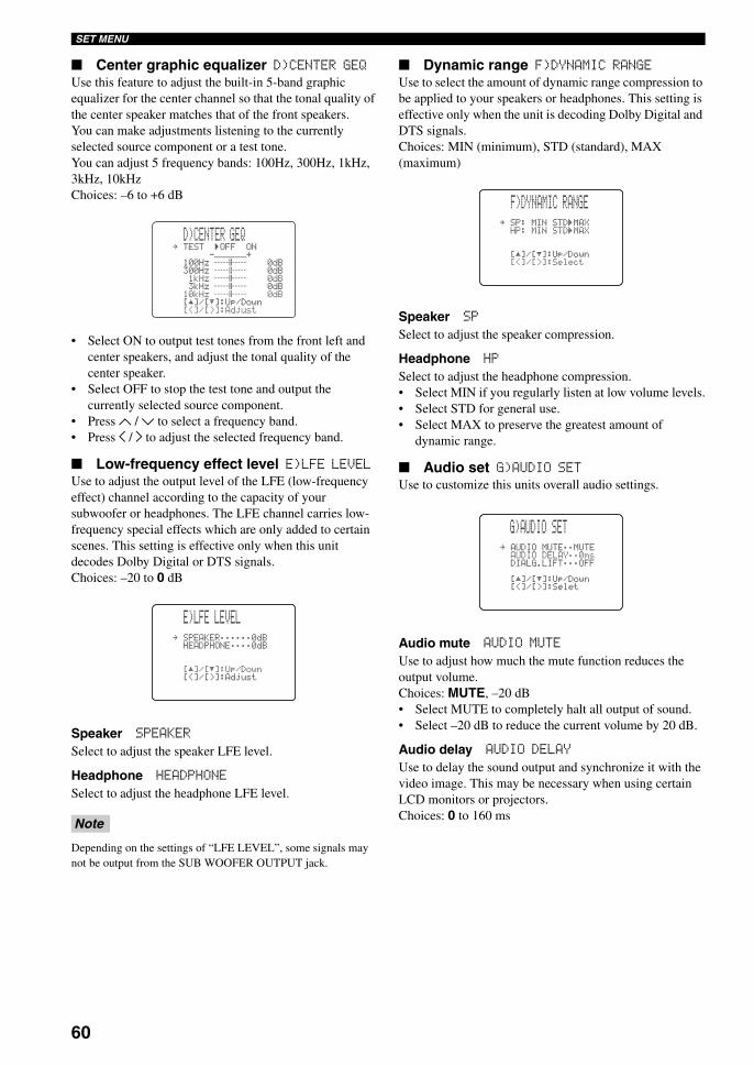
60
SET MENU
Center graphic equalizer D)CENTER GEQUse this feature to adjust the built-in 5-band graphic equalizer for the center channel so that the tonal quality of the center speaker matches that of the front speakers.You can make adjustments listening to the currently selected source component or a test tone.You can adjust 5 frequency bands: 100Hz, 300Hz, 1kHz, 3kHz, 10kHzChoices: –6 to +6 dB
• Select ON to output test tones from the front left and center speakers, and adjust the tonal quality of the center speaker.
• Select OFF to stop the test tone and output the currently selected source component.
• Press u / d to select a frequency band.• Press j / i to adjust the selected frequency band.
Low-frequency effect level E)LFE LEVELUse to adjust the output level of the LFE (low-frequency effect) channel according to the capacity of your subwoofer or headphones. The LFE channel carries low-frequency special effects which are only added to certain scenes. This setting is effective only when this unit decodes Dolby Digital or DTS signals.Choices: –20 to 0 dB
Speaker SPEAKERSelect to adjust the speaker LFE level.
Headphone HEADPHONESelect to adjust the headphone LFE level.
Depending on the settings of “LFE LEVEL”, some signals may not be output from the SUB WOOFER OUTPUT jack.
Dynamic range F)DYNAMIC RANGEUse to select the amount of dynamic range compression to be applied to your speakers or headphones. This setting is effective only when the unit is decoding Dolby Digital and DTS signals.Choices: MIN (minimum), STD (standard), MAX (maximum)
Speaker SPSelect to adjust the speaker compression.
Headphone HPSelect to adjust the headphone compression.• Select MIN if you regularly listen at low volume levels.• Select STD for general use.• Select MAX to preserve the greatest amount of
dynamic range.
Audio set G)AUDIO SETUse to customize this units overall audio settings.
Audio mute AUDIO MUTEUse to adjust how much the mute function reduces the output volume.Choices: MUTE, –20 dB• Select MUTE to completely halt all output of sound.• Select –20 dB to reduce the current volume by 20 dB.
Audio delay AUDIO DELAYUse to delay the sound output and synchronize it with the video image. This may be necessary when using certain LCD monitors or projectors.Choices: 0 to 160 ms
Note
.TEST)OFFON-+100Hz0dB300Hz0dB1kHz0dB3kHz0dB10kHz0dB[]/[]:Up/Down[<]/[>]:Adjust
D)CENTER GEQ
p
p
.SPEAKER;;;;;;0dBHEADPHONE;;;;0dB
[]/[]:Up/Down[<]/[>]:Adjust
p
p
E)LFE LEVEL
.SP:MINSTD)MAXHP:MINSTD)MAX
[]/[]:Up/Down[<]/[>]:Select
p
p
F)DYNAMIC RANGE
.AUDIOMUTE;;MUTEAUDIODELAY;;0msDIALG.LIFT;;;OFF
[]/[]:Up/Down[<]/[>]:Selet
p
p
G)AUDIO SET
01EN_00_RXV750_GB.book Page 60 Thursday, February 12, 2004 5:15 PM
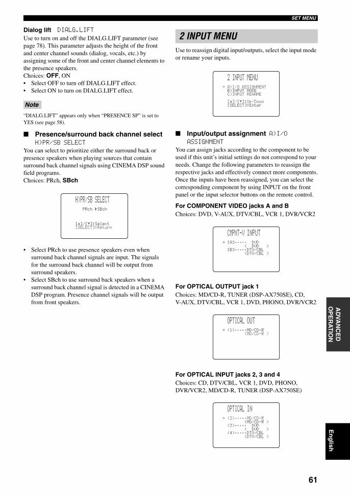
61
En
glish
SET MENUA
DVA
NC
ED
O
PE
RA
TIO
N
Dialog lift DIALG.LIFTUse to turn on and off the DIALG.LIFT parameter (see page 78). This parameter adjusts the height of the front and center channel sounds (dialog, vocals, etc.) by assigning some of the front and center channel elements to the presence speakers.Choices: OFF, ON• Select OFF to turn off DIALG.LIFT effect.• Select ON to turn on DIALG.LIFT effect.
“DIALG.LIFT” appears only when “PRESENCE SP” is set to YES (see page 58).
Presence/surround back channel select H)PR/SB SELECT
You can select to prioritize either the surround back or presence speakers when playing sources that contain surround back channel signals using CINEMA DSP sound field programs.Choices: PRch, SBch
• Select PRch to use presence speakers even when surround back channel signals are input. The signals for the surround back channel will be output from surround speakers.
• Select SBch to use surround back speakers when a surround back channel signal is detected in a CINEMA DSP program. Presence channel signals will be output from front speakers.
Use to reassign digital input/outputs, select the input mode or rename your inputs.
Input/output assignment A)I/O ASSIGNMENT
You can assign jacks according to the component to be used if this unit’s initial settings do not correspond to your needs. Change the following parameters to reassign the respective jacks and effectively connect more components.Once the inputs have been reassigned, you can select the corresponding component by using INPUT on the front panel or the input selector buttons on the remote control.
For COMPONENT VIDEO jacks A and BChoices: DVD, V-AUX, DTV/CBL, VCR 1, DVR/VCR2
For OPTICAL OUTPUT jack 1Choices: MD/CD-R, TUNER (DSP-AX750SE), CD, V-AUX, DTV/CBL, VCR 1, DVD, PHONO, DVR/VCR2
For OPTICAL INPUT jacks 2, 3 and 4Choices: CD, DTV/CBL, VCR 1, DVD, PHONO, DVR/VCR2, MD/CD-R, TUNER (DSP-AX750SE)
Note
PRch)SBch
[]/[]:Select[SELECT]:Return
p
p
H)PR/SBSELECT
2 INPUT MENU
.A)I/OASSIGNMENT B)INPUTMODEC)INPUTRENAME
[]/[]:Up/Down[SELECT]:Enter
2INPUTMENU
p
p
.[A];;;;;DVD(DVD)[B];;;;;DTV/CBL(DTV/CBL)
CMPNT-VINPUT
.(1);;;;;MD/CD-R(MD/CD-R )
OPTICALOUT
.(2);;;;;MD/CD-R(MD/CD-R)
(3);;;;; DVD(DVD )
(4);;;;;DTV/CBL(DTV/CBL )
OPTICALIN
01EN_00_RXV750_GB.book Page 61 Thursday, February 12, 2004 5:15 PM
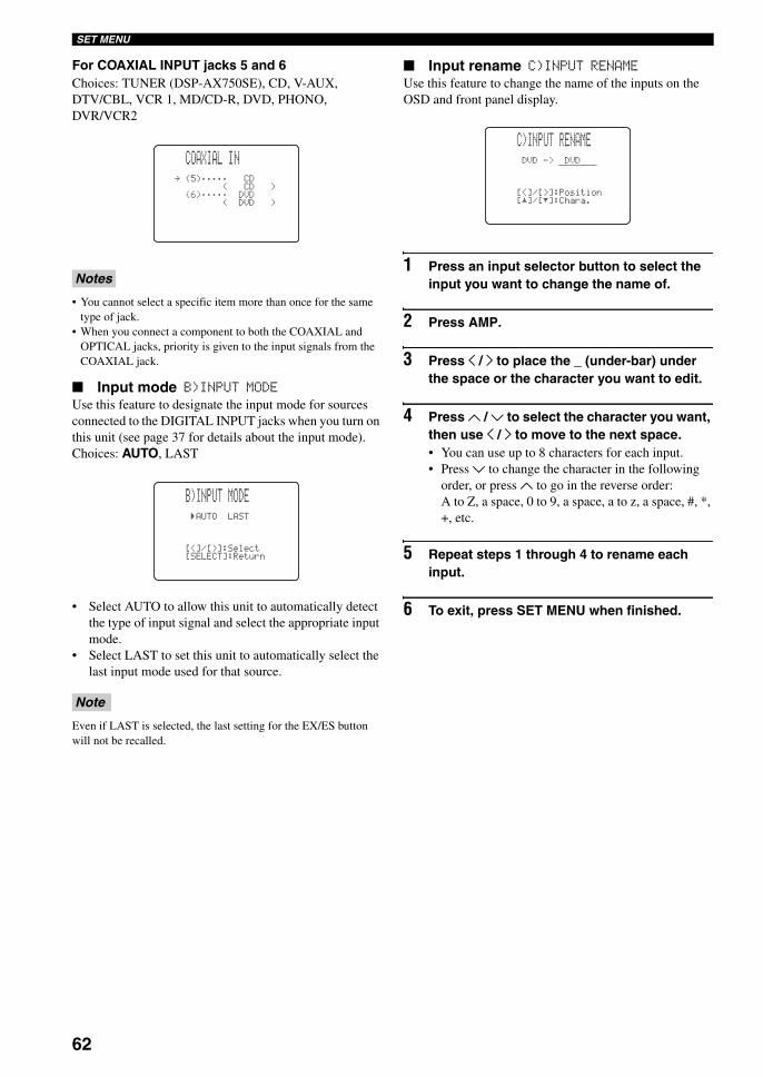
62
SET MENU
For COAXIAL INPUT jacks 5 and 6Choices: TUNER (DSP-AX750SE), CD, V-AUX, DTV/CBL, VCR 1, MD/CD-R, DVD, PHONO, DVR/VCR2
• You cannot select a specific item more than once for the same type of jack.
• When you connect a component to both the COAXIAL and OPTICAL jacks, priority is given to the input signals from the COAXIAL jack.
Input mode B)INPUT MODEUse this feature to designate the input mode for sources connected to the DIGITAL INPUT jacks when you turn on this unit (see page 37 for details about the input mode).Choices: AUTO, LAST
• Select AUTO to allow this unit to automatically detect the type of input signal and select the appropriate input mode.
• Select LAST to set this unit to automatically select the last input mode used for that source.
Even if LAST is selected, the last setting for the EX/ES button will not be recalled.
Input rename C)INPUT RENAMEUse this feature to change the name of the inputs on the OSD and front panel display.
1 Press an input selector button to select the input you want to change the name of.
2 Press AMP.
3 Press j / i to place the _ (under-bar) under the space or the character you want to edit.
4 Press u / d to select the character you want, then use j / i to move to the next space.• You can use up to 8 characters for each input.• Press d to change the character in the following
order, or press u to go in the reverse order:A to Z, a space, 0 to 9, a space, a to z, a space, #, *, +, etc.
5 Repeat steps 1 through 4 to rename each input.
6 To exit, press SET MENU when finished.
Notes
Note
.(5);;;;; CD( CD )
(6);;;;; DVD(DVD )
COAXIALIN
)AUTOLAST
[<]/[>]:Select[SELECT]:Return
B)INPUTMODE
DVD->DVD
[<]/[>]:Position[]/[]:Chara.
C)INPUTRENAME
p
p
01EN_00_RXV750_GB.book Page 62 Thursday, February 12, 2004 5:15 PM
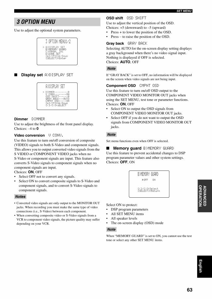
63
En
glish
SET MENUA
DVA
NC
ED
O
PE
RA
TIO
N
Use to adjust the optional system parameters.
Display set A)DISPLAY SET
Dimmer DIMMERUse to adjust the brightness of the front panel display.Choices: –4 to 0
Video conversion V CONV.Use this feature to turn on/off conversion of composite (VIDEO) signals to both S-Video and component signals. This allows you to output converted video signals from the S VIDEO or COMPONENT VIDEO jacks when no S-Video or component signals are input. This feature also converts S-Video signals to component signals when no component signals are input.Choices: ON, OFF• Select OFF not to convert any signals. • Select ON to convert composite signals to S-Video and
component signals, and to convert S-Video signals to component signals.
• Converted video signals are only output to the MONITOR OUT jacks. When recording you must make the same type of video connections (i.e., S-Video) between each component.
• When converting composite video or S-Video signals from a VCR to component video signals, the picture quality may suffer depending on your VCR.
OSD shift OSD SHIFTUse to adjust the vertical position of the OSD.Choices: +5 (downward) to –5 (upward)• Press + to lower the position of the OSD.• Press – to raise the position of the OSD.
Gray back GRAY BACKSelecting AUTO for the on-screen display setting displays a gray background when there’s no video signal input. Nothing is displayed if OFF is selected.Choices: AUTO, OFF
If “GRAY BACK” is set to OFF, no information will be displayed on the screen when video signals are not being input.
Component OSD CMPNT OSD
Use this feature to turn on/off OSD output to the COMPONENT VIDEO MONITOR OUT jacks when using the SET MENU, test tone or parameter functions.Choices: ON, OFF• Select ON to output the OSD signals from
COMPONENT VIDEO MONITOR OUT jacks.• Select OFF if you do not want to output the OSD
signals from COMPONENT VIDEO MONITOR OUT jacks.
Set menu functions even when OFF is selected.
Memory guard B)MEMORY GUARDUse this feature to prevent accidental changes to DSP program parameter values and other system settings.Choices: OFF, ON
Select ON to protect:• DSP program parameters• All SET MENU items• All speaker levels• The on-screen display (OSD) mode
When “MEMORY GUARD” is set to ON, you cannot use the test tone or select any other SET MENU items.
3 OPTION MENU
Notes
.A)DISPLAYSETB)MEMORYGUARDC)PARAM.INID)ZONESET
[]/[]:Up/Down[SELECT]:Enter
3OPTIONMENU1/2
p
p
.DIMMER;;;;;;;;;0VCONV;;;;;;;;ONOSDSHIFT;;;;;;0GRAYBACK;;;AUTOCMPNTOSD;;;;;ON[]/[]:Up/Down[<]/[>]:sELECT
A)DISPLAYSET
p
p
Note
Note
Note
)OFFON
[<]/[>]:Select[SELECT]:Return
B)MEMORYGUARD
01EN_00_RXV750_GB.book Page 63 Thursday, February 12, 2004 5:15 PM
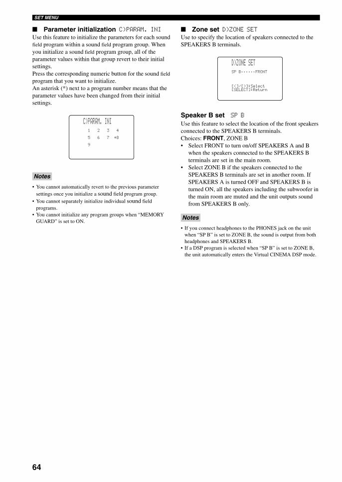
64
SET MENU
Parameter initialization C)PARAM. INIUse this feature to initialize the parameters for each sound field program within a sound field program group. When you initialize a sound field program group, all of the parameter values within that group revert to their initial settings.Press the corresponding numeric button for the sound field program that you want to initialize.An asterisk (*) next to a program number means that the parameter values have been changed from their initial settings.
• You cannot automatically revert to the previous parameter settings once you initialize a sound field program group.
• You cannot separately initialize individual sound field programs.
• You cannot initialize any program groups when “MEMORY GUARD” is set to ON.
Zone set D)ZONE SETUse to specify the location of speakers connected to the SPEAKERS B terminals.
Speaker B set SP BUse this feature to select the location of the front speakers connected to the SPEAKERS B terminals.Choices: FRONT, ZONE B• Select FRONT to turn on/off SPEAKERS A and B
when the speakers connected to the SPEAKERS B terminals are set in the main room.
• Select ZONE B if the speakers connected to the SPEAKERS B terminals are set in another room. If SPEAKERS A is turned OFF and SPEAKERS B is turned ON, all the speakers including the subwoofer in the main room are muted and the unit outputs sound from SPEAKERS B only.
• If you connect headphones to the PHONES jack on the unit when “SP B” is set to ZONE B, the sound is output from both headphones and SPEAKERS B.
• If a DSP program is selected when “SP B” is set to ZONE B, the unit automatically enters the Virtual CINEMA DSP mode.
Notes
1234
567*8
9
C)PARAM.INI
Notes
SPB;;;;;;FRONT
[<]/[>]:Select[SELECT]:Return
D)ZONESET
01EN_00_RXV750_GB.book Page 64 Thursday, February 12, 2004 5:15 PM
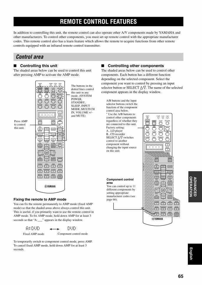
REMOTE CONTROL FEATURES
65
En
glish
AD
VAN
CE
D
OP
ER
AT
ION
In addition to controlling this unit, the remote control can also operate other A/V components made by YAMAHA and other manufacturers. To control other components, you must set up remote control with the appropriate manufacturer codes. This remote control also has a learn feature which allows the remote to acquire functions from other remote controls equipped with an infrared remote control transmitter.
Controlling this unitThe shaded areas below can be used to control this unit after pressing AMP to activate the AMP mode.
Fixing the remote to AMP modeYou can fix the remote permanently to AMP mode (fixed AMP mode) so that the shaded areas above always control this unit. This is useful, if you primarily want to use the remote control in AMP mode. To fix AMP mode, hold down AMP for at least 3 seconds so that “A:___” appears in the display window.
To temporarily switch to component control mode, press AMP.To cancel fixed AMP mode, hold down AMP for at least 3 seconds.
Controlling other componentsThe shaded areas below can be used to control other components. Each button has a different function depending on the selected component. Select the component you want to control by pressing an input selector button or SELECT k/n. The name of the selected component appears in the display window.
REMOTE CONTROL FEATURES
Control area
TRANSMIT RE-NAME
INPUT MODESTANDBYSYSTEMPOWER
A B PHONO
CDMD/CD-RTUNERV-AUX
DVD
AMPPOWERPOWER
REC
AUDIO
MUTE
MENUTITLE
CH CH
VOL
DISC SKIP
FREQ/RDS EON
STARTSET MENULEVEL
A/B/C/D/ETV INPUT
MODE PTY SEEK
TV VOL
PRESET
TEST ON SCREEN STRAIGHT
ROCKJAZZHALLSTEREO
4321
8
10
7
09
65
ENTER
MOVIETV THTRMUSIC ENTERTAIN
EX/ESNIGHTq/DTS PURE DIRECT
EFFECT
CHP/INDEX
DISPLAYRETURN
PRESET
TV MUTESELECT
TV VOL
AVTV
SELECT
VCR 1DTV/CBL DVR/VCR2
MULTI CH IN
SLEEP
CLEAR LEARN
The buttons in the dotted lines control this unit in any mode. (SYSTEM POWER, STANDBY, SLEEP, INPUT MODE, MULTI CH IN, VOLUME +/– and MUTE)
Press AMP to control this unit.
Fixed AMP mode Component control mode
A:DVD DVD
TRANSMIT RE-NAME
INPUT MODESTANDBYSYSTEMPOWER
A B PHONO
CDMD/CD-RTUNERV-AUX
DVD
AMPPOWERPOWER
REC
AUDIO
MUTE
MENUTITLE
CH CH
VOL
DISC SKIP
FREQ/RDS EON
STARTSET MENULEVEL
A/B/C/D/ETV INPUT
CHP/INDEX
MODE PTY SEEK
TV VOL
PRESET
TEST ON SCREEN STRAIGHT
ROCKJAZZHALLSTEREO
4321
8
10
7
09
65
ENTER
MOVIETV THTRMUSIC ENTERTAIN
EX/ESNIGHTq/DTS PURE DIRECT
EFFECT
DISPLAYRETURN
PRESET
TV MUTESELECT
TV VOL
AVTV
SELECT
VCR 1DTV/CBL DVR/VCR2
MULTI CH IN
SLEEP
CLEAR LEARN
POWERPOWER
REC
AUDIO
MENUTITLE
CH CH
DISC SKIP
FREQ/RDS EON
STARTSET MENULEVEL
A/B/C/D/ETV INPUT
CHP/INDEX
MODE PTY SEEK
TV VOL
PRESET
TEST ON SCREEN
ROCKJAZZHALLSTEREO
4321
8
10
7
09
65
ENTER
MOVIETV THTRMUSIC ENTERTAIN
EX/ESNIGHTq/DTS PURE DIRECT
DISPLAYRETURN
PRESET
TV MUTESELECT
TV VOL
AVTV
A/B buttons and the input selector buttons switch the function of the component control area below.* Use the A/B buttons to control other components regardless of whether they are connected to this unit.Factory setting:A...LD playerB...CD recorderSELECT k/n switches control to another component without changing the input source on this unit.
Component control areaYou can control up to 11 different components by setting appropriate manufacturer codes (see page 66).
01EN_00_RXV750_GB.book Page 65 Thursday, February 12, 2004 5:15 PM
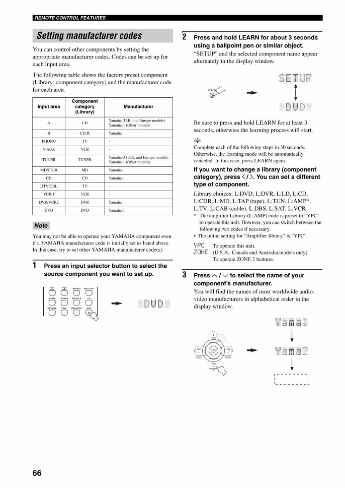
66
REMOTE CONTROL FEATURES
You can control other components by setting the appropriate manufacturer codes. Codes can be set up for each input area.
The following table shows the factory preset component (Library: component category) and the manufacturer code for each area.
You may not be able to operate your YAMAHA component even if a YAMAHA manufacturer code is initially set as listed above. In this case, try to set other YAMAHA manufacturer code(s).
1 Press an input selector button to select the source component you want to set up.
2 Press and hold LEARN for about 3 seconds using a ballpoint pen or similar object.“SETUP” and the selected component name appear alternately in the display window.
Be sure to press and hold LEARN for at least 3 seconds, otherwise the learning process will start.
yComplete each of the following steps in 30 seconds. Otherwise, the learning mode will be automatically canceled. In this case, press LEARN again.
If you want to change a library (component category), press j / i. You can set a different type of component.
Library choices: L:DVD, L:DVR, L:LD, L:CD, L:CDR, L:MD, L:TAP (tape), L:TUN, L:AMP*, L:TV, L:CAB (cable), L:DBS, L:SAT, L:VCR* The amplifier Library (L:AMP) code is preset to “YPC”
to operate this unit. However, you can switch between the following two codes if necessary.
• The initial setting for “Amplifier library” is “YPC”.
YPC To operate this unit.ZONE (U.S.A., Canada and Australia models only)
To operate ZONE 2 features.
3 Press u / d to select the name of your component’s manufacturer.You will find the names of most worldwide audio-video manufacturers in alphabetical order in the display window.
Setting manufacturer codes
Input areaComponent
category (Library)
Manufacturer
A LDYamaha (U.K. and Europe models)Yamaha-1 (Other models)
B CD-R Yamaha
PHONO TV –
V-AUX VCR –
TUNER TUNERYamaha-3 (U.K. and Europe models)Yamaha-1 (Other models)
MD/CD-R MD Yamaha-1
CD CD Yamaha-1
DTV/CBL TV –
VCR 1 VCR –
DVR/VCR2 DVR Yamaha
DVD DVD Yamaha-1
Note
A B PHONO
CDMD/CD-RTUNERV-AUX
DVDVCR 1DTV/CBL DVR/VCR2
MULTI CH IN
LEARN
TV VOL
PRESET PRESET
TV MUTE
TV VOL
SELECT
CHCH
+
+–
–
01EN_00_RXV750_GB.book Page 66 Thursday, February 12, 2004 5:15 PM
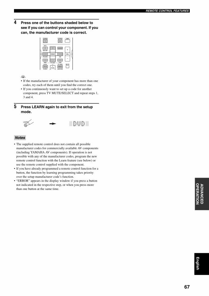
67
En
glish
REMOTE CONTROL FEATURESA
DVA
NC
ED
O
PE
RA
TIO
N
4 Press one of the buttons shaded below to see if you can control your component. If you can, the manufacturer code is correct.
y• If the manufacturer of your component has more than one
codes, try each of them until you find the correct one.• If you continuously want to set up a code for another
component, press TV MUTE/SELECT and repeat steps 1, 3 and 4.
5 Press LEARN again to exit from the setup mode.
• The supplied remote control does not contain all possible manufacturer codes for commercially available AV components (including YAMAHA AV components). If operation is not possible with any of the manufacturer codes, program the new remote control function with the Learn feature (see below) or use the remote control supplied with the component.
• If you have already programmed a remote control function for a button, the function by learning programming takes priority over the setup manufacturer code’s function.
• “ERROR” appears in the display window if you press a button not indicated in the respective step, or when you press more than one button at the same time.
Notes
AMPPOWERPOWER
REC
AUDIO
MUTE
MENUTITLE
VOL
DISC SKIP
FREQ/RDS EON
STARTSET MENULEVEL
A/B/C/D/ETV INPUT
MODE PTY SEEK
TV VOL
AVTV
LEARN
01EN_00_RXV750_GB.book Page 67 Thursday, February 12, 2004 5:15 PM
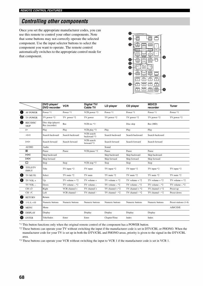
68
REMOTE CONTROL FEATURES
Once you set the appropriate manufacturer codes, you can use this remote to control your other components. Note that some buttons may not correctly operate the selected component. Use the input selector buttons to select the component you want to operate. The remote control automatically switches to the appropriate control mode for that component.
*1 This button functions only when the original remote control of the component has a POWER button.*2 These buttons can operate your TV without switching the input if the manufacturer code is set in DTV/CBL or PHONO. When the
manufacturer code for your TV is set up in both the DTV/CBL and PHONO areas, priority is given to the signal in the DTV/CBL area.
*3 These buttons can operate your VCR without switching the input to VCR 1 if the manufacturer code is set in VCR 1.
Controlling other components
AMPPOWERPOWER
REC
AUDIO
MUTE
MENUTITLE
CH CH
VOL
DISC SKIP
FREQ/RDS EON
STARTSET MENULEVEL
A/B/C/D/ETV INPUT
MODE PTY SEEK
TV VOL
PRESET
TEST ON SCREEN STRAIGHT
ROCKJAZZHALLSTEREO
4321
8
10
7
09
65
ENTER
MOVIETV THTRMUSIC ENTERTAIN
EX/ESNIGHTq/DTS PURE DIRECT
EFFECT
CHP/INDEX
DISPLAYRETURN
PRESET
TV MUTESELECT
TV VOL
AVTV
3
2
1
456
8
7
9
0
A
DVD player/DVD recorder VCR Digital TV/
Cable TV LD player CD player MD/CD recorder Tuner
1 AV POWER Power *1 Power *1 VCR power *3 Power *1 Power *1 Power *1 Power *1
2 TV POWER TV power *2 TV power *2 TV power TV power *2 TV power *2 TV power *2 TV power *2
3 REC/DISC SKIP
Disc skip (player)Rec (recorder)
Rec VCR rec *3 Disc skip Rec (MD)
h Play Play VCR play *3 Play Play Play
ll Search backward Search backwardVCR search backward *3
Search backward Search backward Search backward
hh Search forward Search forwardVCR search forward *3
Search forward Search forward Search forward
AUDIO Audio Sound
e Pause Pause VCR pause *3 Pause Pause Pause
b Skip backward Skip backward Skip backward Skip backward
a Skip forward Skip forward Skip forward Skip forward
s Stop Stop VCR stop *3 Stop Stop Stop
4 TITLE/TV INPUT
Title TV input *2 TV input TV input *2 TV input *2 TV input *2 TV input *2
5 TV MUTE Select TV mute *2 TV mute TV mute *2 TV mute *2 TV mute *2 TV mute *2
6 TV VOL + Up TV volume + *2 TV volume + TV volume + *2 TV volume + *2 TV volume + *2 TV volume + *2
TV VOL – Down TV volume – *2 TV volume – TV volume – *2 TV volume – *2 TV volume – *2 TV volume – *2
CH +/i Right VCR channel + TV channel + TV channel + *2 TV channel + *2 TV channel + *2 Preset up
CH –/j Left VCR channel – TV channel – TV channel – *2 TV channel – *2 TV channel – *2 Preset down
7 RETURN Return
8 1-9, 0, +10 Numeric buttons Numeric buttons Numeric buttons Numeric buttons Numeric buttons Numeric buttons Preset stations (1-8)
9 MENU Menu A/B/C/D/E
0 DISPLAY Display Display Display Display Display
A ENTER Title/Index Enter Enter Chapter/Time Index Index
01EN_00_RXV750_GB.book Page 68 Thursday, February 12, 2004 5:15 PM
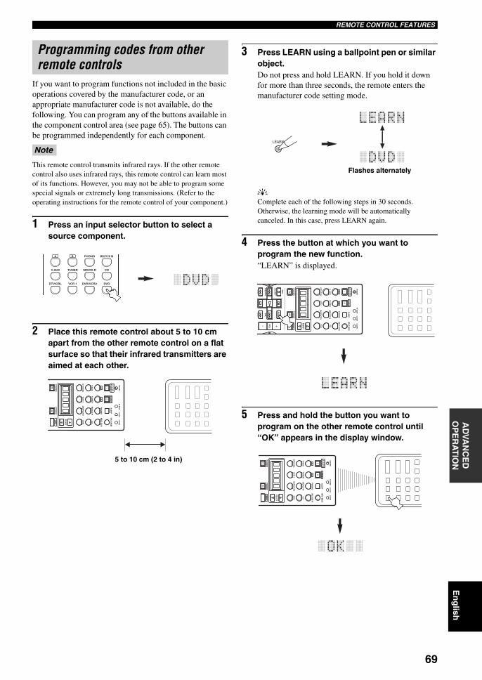
69
En
glish
REMOTE CONTROL FEATURESA
DVA
NC
ED
O
PE
RA
TIO
N
If you want to program functions not included in the basic operations covered by the manufacturer code, or an appropriate manufacturer code is not available, do the following. You can program any of the buttons available in the component control area (see page 65). The buttons can be programmed independently for each component.
This remote control transmits infrared rays. If the other remote control also uses infrared rays, this remote control can learn most of its functions. However, you may not be able to program some special signals or extremely long transmissions. (Refer to the operating instructions for the remote control of your component.)
1 Press an input selector button to select a source component.
2 Place this remote control about 5 to 10 cm apart from the other remote control on a flat surface so that their infrared transmitters are aimed at each other.
3 Press LEARN using a ballpoint pen or similar object.Do not press and hold LEARN. If you hold it down for more than three seconds, the remote enters the manufacturer code setting mode.
yComplete each of the following steps in 30 seconds. Otherwise, the learning mode will be automatically canceled. In this case, press LEARN again.
4 Press the button at which you want to program the new function.“LEARN” is displayed.
5 Press and hold the button you want to program on the other remote control until “OK” appears in the display window.
Programming codes from other remote controls
Note
A B PHONO
CDMD/CD-RTUNERV-AUX
DVDVCR 1DTV/CBL DVR/VCR2
MULTI CH IN
TRANSMIT
RE-NAME
INPUT MODE
STANDBYS
YS
TE
MP
OW
ER
AB
PH
ON
O
CD
MD
/CD
-RT
UN
ER
V-A
UX
DV
D
AM
PP
OW
ER
PO
WE
R
AV
TV
SELECT
VC
R 1
DT
V/C
BL
DV
R/V
CR
2
MULTI CH IN
SL
EE
P CL
EA
RL
EA
RN
5 to 10 cm (2 to 4 in)
Flashes alternately
LEARN
TRANSMIT
RE-NAME
INPUT MODE
STANDBYS
YS
TE
MP
OW
ER
AB
PH
ON
O
CD
MD
/CD
-RT
UN
ER
V-A
UX
DV
D
AM
PP
OW
ER
PO
WE
R
RE
C
AU
DIO
VO
L
DISC SKIP
FREQ/RDSEON
STARTM
ODE
AV
TV
SELECT
VC
R 1
DT
V/C
BL
DV
R/V
CR
2
MULTI CH IN
SL
EE
P CL
EA
RL
EA
RN
TRANSMIT
RE-NAME
INPUT MODE
STANDBYS
YS
TE
MP
OW
ER
AB
PH
ON
O
CD
MD
/CD
-RT
UN
ER
V-A
UX
DV
D
AM
PP
OW
ER
PO
WE
R
AV
TV
SELECT
VC
R 1
DT
V/C
BL
DV
R/V
CR
2
MULTI CH IN
SL
EE
P CL
EA
RL
EA
RN
01EN_00_RXV750_GB.book Page 69 Thursday, February 12, 2004 5:15 PM
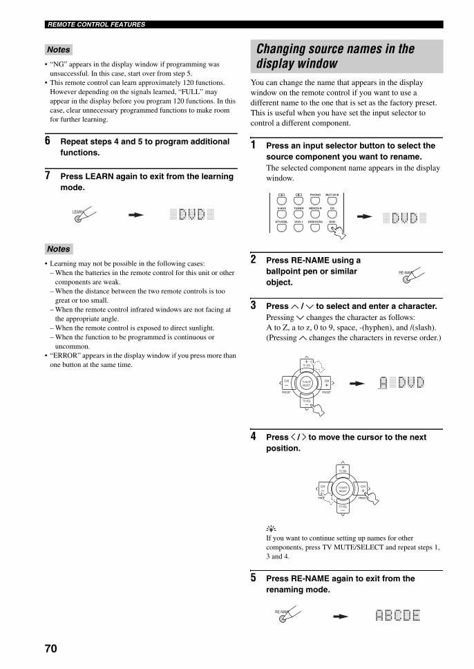
70
REMOTE CONTROL FEATURES
• “NG” appears in the display window if programming was unsuccessful. In this case, start over from step 5.
• This remote control can learn approximately 120 functions. However depending on the signals learned, “FULL” may appear in the display before you program 120 functions. In this case, clear unnecessary programmed functions to make room for further learning.
6 Repeat steps 4 and 5 to program additional functions.
7 Press LEARN again to exit from the learning mode.
• Learning may not be possible in the following cases:– When the batteries in the remote control for this unit or other
components are weak.– When the distance between the two remote controls is too
great or too small.– When the remote control infrared windows are not facing at
the appropriate angle.– When the remote control is exposed to direct sunlight.– When the function to be programmed is continuous or
uncommon.• “ERROR” appears in the display window if you press more than
one button at the same time.
You can change the name that appears in the display window on the remote control if you want to use a different name to the one that is set as the factory preset. This is useful when you have set the input selector to control a different component.
1 Press an input selector button to select the source component you want to rename.The selected component name appears in the display window.
2 Press RE-NAME using a ballpoint pen or similar object.
3 Press u / d to select and enter a character.Pressing d changes the character as follows:A to Z, a to z, 0 to 9, space, -(hyphen), and /(slash).(Pressing u changes the characters in reverse order.)
4 Press j / i to move the cursor to the next position.
yIf you want to continue setting up names for other components, press TV MUTE/SELECT and repeat steps 1, 3 and 4.
5 Press RE-NAME again to exit from the renaming mode.
Notes
Notes
LEARN
Changing source names in the display window
A B PHONO
CDMD/CD-RTUNERV-AUX
DVDVCR 1DTV/CBL DVR/VCR2
MULTI CH IN
RE-NAME
TV VOL
PRESET PRESET
TV MUTE
TV VOL
SELECT
CHCH
+
+–
–
TV VOL
PRESET PRESET
TV MUTE
TV VOL
SELECT
CHCH
+
+–
–
RE-NAME
01EN_00_RXV750_GB.book Page 70 Thursday, February 12, 2004 5:15 PM
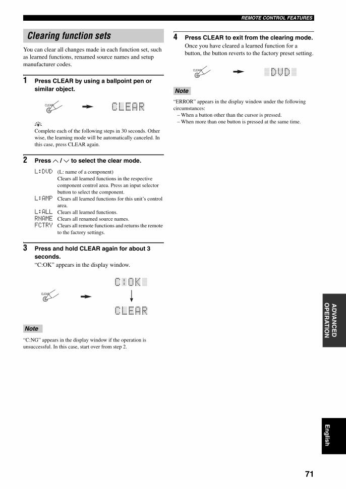
71
En
glish
REMOTE CONTROL FEATURESA
DVA
NC
ED
O
PE
RA
TIO
N
You can clear all changes made in each function set, such as learned functions, renamed source names and setup manufacturer codes.
1 Press CLEAR by using a ballpoint pen or similar object.
yComplete each of the following steps in 30 seconds. Other wise, the learning mode will be automatically canceled. In this case, press CLEAR again.
2 Press u / d to select the clear mode.
L:DVD (L: name of a component)Clears all learned functions in the respective component control area. Press an input selector button to select the component.
L:AMP Clears all learned functions for this unit’s control area.
L:ALL Clears all learned functions.RNAME Clears all renamed source names.FCTRY Clears all remote functions and returns the remote
to the factory settings.
3 Press and hold CLEAR again for about 3 seconds.“C:OK” appears in the display window.
“C:NG” appears in the display window if the operation is unsuccessful. In this case, start over from step 2.
4 Press CLEAR to exit from the clearing mode.Once you have cleared a learned function for a button, the button reverts to the factory preset setting.
“ERROR” appears in the display window under the following circumstances:
– When a button other than the cursor is pressed.– When more than one button is pressed at the same time.
Clearing function sets
Note
CLEAR
CLEAR
Note
CLEAR
01EN_00_RXV750_GB.book Page 71 Thursday, February 12, 2004 5:15 PM
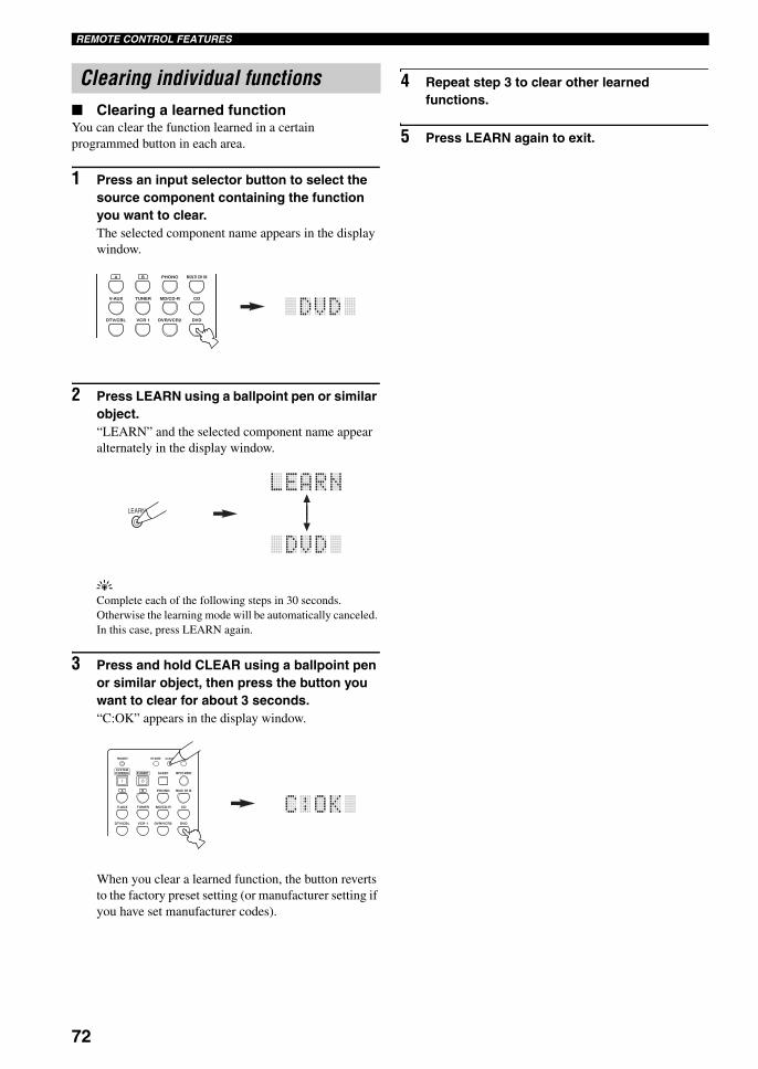
72
REMOTE CONTROL FEATURES
Clearing a learned functionYou can clear the function learned in a certain programmed button in each area.
1 Press an input selector button to select the source component containing the function you want to clear.The selected component name appears in the display window.
2 Press LEARN using a ballpoint pen or similar object.“LEARN” and the selected component name appear alternately in the display window.
yComplete each of the following steps in 30 seconds. Otherwise the learning mode will be automatically canceled. In this case, press LEARN again.
3 Press and hold CLEAR using a ballpoint pen or similar object, then press the button you want to clear for about 3 seconds.“C:OK” appears in the display window.
When you clear a learned function, the button reverts to the factory preset setting (or manufacturer setting if you have set manufacturer codes).
4 Repeat step 3 to clear other learned functions.
5 Press LEARN again to exit.
Clearing individual functions
A B PHONO
CDMD/CD-RTUNERV-AUX
DVDVCR 1DTV/CBL DVR/VCR2
MULTI CH IN
LEARN
TRANSMIT RE-NAME
INPUT MODESTANDBYSYSTEMPOWER
A B PHONO
CDMD/CD-RTUNERV-AUX
DVDVCR 1DTV/CBL DVR/VCR2
MULTI CH IN
SLEEP
CLEAR LEARN
01EN_00_RXV750_GB.book Page 72 Thursday, February 12, 2004 5:15 PM
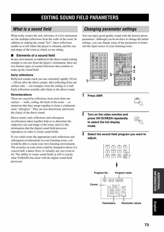
EDITING SOUND FIELD PARAMETERS
73
En
glish
AD
DIT
ION
AL
IN
FO
RM
AT
ION
What really creates the rich, full tones of a live instrument are the multiple reflections from the walls of the room. In addition to making the sound “live”, these reflections enable us to tell where the player is situated, and the size and shape of the room in which we are sitting.
Elements of a sound fieldIn any environment, in addition to the direct sound coming straight to our ears from the player’s instrument, there are two distinct types of sound reflections that combine to make up the sound field:
Early reflectionsReflected sounds reach our ears extremely rapidly (50 ms – 100 ms after the direct sound), after reflecting from one surface only — for example, from the ceiling or a wall. Early reflections actually add clarity to the direct sound.
ReverberationsThese are caused by reflections from more than one surface — walls, ceiling, the back of the room — so numerous that they merge together to form a continuous sonic “afterglow”. They are non-directional, and lessen the clarity of the direct sound.
Direct sound, early reflections and subsequent reverberation taken together help us to determine the subjective size and shape of the room, and it is this information that the digital sound field processor reproduces in order to create sound fields.
If you could create the appropriate early reflections and subsequent reverberations in your listening room, you would be able to create your own listening environment. The acoustics in your room could be changed to those of a concert hall, a dance floor, or virtually any size room at all. This ability to create sound fields at will is exactly what YAMAHA has done with the digital sound field processor.
You can enjoy good quality sound with the factory preset parameters. Although you do not have to change the initial settings, you can change some of the parameters to better suit the input source or your listening room.
1 Press AMP.
2 Turn on the video monitor and press ON SCREEN repeatedly to select the full display mode.
3 Select the sound field program you want to adjust.
EDITING SOUND FIELD PARAMETERS
What is a sound field Changing parameter settings
TRANSMIT RE-NAME
INPUT MODESTANDBYSYSTEMPOWER
A B PHONO
CDMD/CD-RTUNERV-AUX
DVD
AMPPOWERPOWER
REC
AVTV
SELECT
VCR 1DTV/CBL DVR/VCR2
MULTI CH IN
SLEEP
CLEAR LEARNREC
AUDIO
MUTE
MENUTITLE
CH CH
VOL
DISC SKIP
FREQ/RDS EON
STARTSET MENULEVEL
A/B/C/D/ETV INPUT
MODE PTY SEEK
TV VOL
PRESET
TEST ON SCREEN STRAIGHT
ROCKJAZZHALLSTEREO
4321
8
10
7
09
65
ENTER
MOVIETV THTRMUSIC ENTERTAIN
EX/ESNIGHTq/DTS PURE DIRECT
EFFECT
CHP/INDEX
DISPLAYRETURN
PRESET
TV MUTESELECT
TV VOL
AVTV
24
531
AMP
ON SCREEN
DISPLAY
ROCKJAZZHALLSTEREO
4321
8
10
7
09
65
ENTER
MOVIETV THTRMUSIC ENTERTAIN
EX/ESNIGHTq/DTS PURE DIRECT
CHP/INDEX
P08 MOVIE THEATER
.GeneralDSPLEVEL;;;;0dBP.INIT.DLY;;15msP.ROOMSIZE;;1.0S.INIT.DLY;;20msS.ROOMSIZE;;1.0
Program No. Program name
Parameters Parameter values
Cursor
01EN_00_RXV750_GB.book Page 73 Thursday, February 12, 2004 5:15 PM
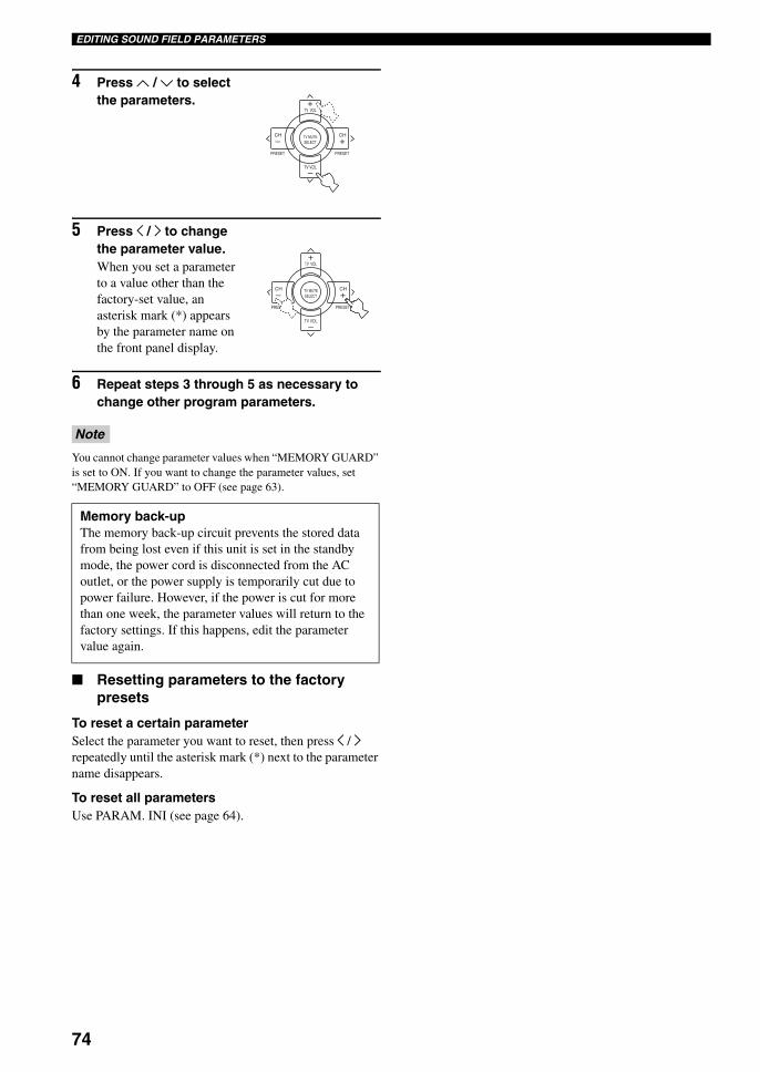
74
EDITING SOUND FIELD PARAMETERS
4 Press u / d to select the parameters.
5 Press j / i to change the parameter value.When you set a parameter to a value other than the factory-set value, an asterisk mark (*) appears by the parameter name on the front panel display.
6 Repeat steps 3 through 5 as necessary to change other program parameters.
You cannot change parameter values when “MEMORY GUARD” is set to ON. If you want to change the parameter values, set “MEMORY GUARD” to OFF (see page 63).
Resetting parameters to the factory presets
To reset a certain parameterSelect the parameter you want to reset, then press j / i repeatedly until the asterisk mark (*) next to the parameter name disappears.
To reset all parametersUse PARAM. INI (see page 64).
Note
Memory back-upThe memory back-up circuit prevents the stored data from being lost even if this unit is set in the standby mode, the power cord is disconnected from the AC outlet, or the power supply is temporarily cut due to power failure. However, if the power is cut for more than one week, the parameter values will return to the factory settings. If this happens, edit the parameter value again.
TV VOL
PRESET PRESET
TV MUTE
TV VOL
SELECT
CHCH
+
+–
–
TV VOL
PRESET PRESET
TV MUTE
TV VOL
SELECT
CHCH
+
+–
–
01EN_00_RXV750_GB.book Page 74 Thursday, February 12, 2004 5:15 PM
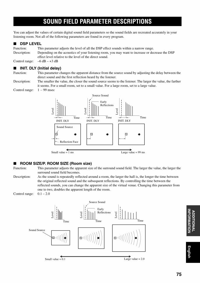
SOUND FIELD PARAMETER DESCRIPTIONS
75
En
glish
AD
DIT
ION
AL
IN
FO
RM
AT
ION
You can adjust the values of certain digital sound field parameters so the sound fields are recreated accurately in your listening room. Not all of the following parameters are found in every program.
DSP LEVELFunction: This parameter adjusts the level of all the DSP effect sounds within a narrow range.Description: Depending on the acoustics of your listening room, you may want to increase or decrease the DSP
effect level relative to the level of the direct sound.Control range: –6 dB – +3 dB
INIT. DLY (Initial delay)Function: This parameter changes the apparent distance from the source sound by adjusting the delay between the
direct sound and the first reflection heard by the listener.Description: The smaller the value, the closer the sound source seems to the listener. The larger the value, the farther
it seems. For a small room, set to a small value. For a large room, set to a large value.Control range: 1 – 99 msec
ROOM SIZE/P. ROOM SIZE (Room size)Function: This parameter adjusts the apparent size of the surround sound field. The larger the value, the larger the
surround sound field becomes.Description: As the sound is repeatedly reflected around a room, the larger the hall is, the longer the time between
the original reflected sound and the subsequent reflections. By controlling the time between the reflected sounds, you can change the apparent size of the virtual venue. Changing this parameter from one to two, doubles the apparent length of the room.
Control range: 0.1 – 2.0
SOUND FIELD PARAMETER DESCRIPTIONS
Source Sound
Early Reflections
Time Time TimeINIT. DLY INIT. DLY INIT. DLY
Sound Source
Reflection Face
Lev
el
Small value = 1 ms Large value = 99 ms
Lev
el
Lev
el
Lev
el
Lev
el
Lev
el
Time Time Time
Source Sound
Early Reflections
Small value = 0.1 Large value = 2.0
Sound Source
01EN_00_RXV750_GB.book Page 75 Thursday, February 12, 2004 5:15 PM
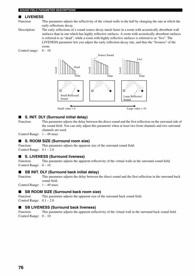
76
SOUND FIELD PARAMETER DESCRIPTIONS
LIVENESSFunction: This parameter adjusts the reflectivity of the virtual walls in the hall by changing the rate at which the
early reflections decay.Description: The early reflections of a sound source decay much faster in a room with acoustically absorbent wall
surfaces than in one which has highly reflective surfaces. A room with acoustically absorbent surfaces is referred to as “dead”, while a room with highly reflective surfaces is referred to as “live”. The LIVENESS parameter lets you adjust the early reflection decay rate, and thus the “liveness” of the room.
Control range: 0 – 10
S. INIT. DLY (Surround initial delay)Function: This parameter adjusts the delay between the direct sound and the first reflection on the surround side of
the sound field. You can only adjust this parameter when at least two front channels and two surround channels are used.
Control Range: 1 – 49 msec
S. ROOM SIZE (Surround room size)Function: This parameter adjusts the apparent size of the surround sound field.Control Range: 0.1 – 2.0
S. LIVENESS (Surround liveness)Function: This parameter adjusts the apparent reflectivity of the virtual walls in the surround sound field.Control Range: 0 – 10
SB INIT. DLY (Surround back initial delay)Function: This parameter adjusts the delay between the direct sound and the first reflection in the surround back
sound field.Control Range: 1 – 49 msec
SB ROOM SIZE (Surround back room size)Function: This parameter adjusts the apparent size of the surround back sound field.Control Range: 0.1 – 2.0
SB LIVENESS (Surround back liveness)Function: This parameter adjusts the apparent reflectivity of the virtual wall in the surround back sound field.Control Range: 0 – 10
Source SoundL
evel
Lev
el
Lev
elDead
Live
Time Time Time
Small Reflected Sound
Large Reflected Sound
Small value = 0 Large value = 10
01EN_00_RXV750_GB.book Page 76 Thursday, February 12, 2004 5:15 PM
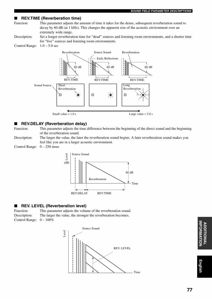
77
En
glish
SOUND FIELD PARAMETER DESCRIPTIONSA
DD
ITIO
NA
L
INF
OR
MA
TIO
N
REV.TIME (Reverberation time)Function: This parameter adjusts the amount of time it takes for the dense, subsequent reverberation sound to
decay by 60 dB (at 1 kHz). This changes the apparent size of the acoustic environment over an extremely wide range.
Description: Set a longer reverberation time for “dead” sources and listening room environments, and a shorter time for “live” sources and listening room environments.
Control Range: 1.0 – 5.0 sec
REV.DELAY (Reverberation delay)Function: This parameter adjusts the time difference between the beginning of the direct sound and the beginning
of the reverberation sound.Description: The larger the value, the later the reverberation sound begins. A later reverberation sound makes you
feel like you are in a larger acoustic environment.Control Range: 0 – 250 msec
REV. LEVEL (Reverberation level)Function: This parameter adjusts the volume of the reverberation sound.Description: The larger the value, the stronger the reverberation becomes.Control Range: 0 – 100%
Reverberation Reverberation
60 dB 60 dB 60 dB
Source Sound
REV.TIME REV.TIME REV.TIME
Early Reflections
Sound Source Short Reverberation
Long Reverberation
Small value = 1.0 s Large value = 5.0 s
(dB)
60 dB
Lev
el Source Sound
Reverberation
REV.TIMEREV.DELAY
Time
Source Sound
Lev
el
REV. LEVEL
Time
01EN_00_RXV750_GB.book Page 77 Thursday, February 12, 2004 5:15 PM
78
SOUND FIELD PARAMETER DESCRIPTIONS
DIALG.LIFT (Dialog lift)Function: This parameter adjusts the height of the front and center channel sounds by assigning some of the front
and center channel elements to the presence speakers.Description: The larger the parameter, the higher the position of the front and center channel sound.Choices: 0/1/2/3/4/5, initial setting is 3.
For 7ch StereoFunction: These parameter adjusts the volume level for each channel in 7-channel stereo mode.Control Range: 0 – 100%
CT LEVEL (Center level)
SL LEVEL (Surround left level)
SR LEVEL (Surround right level)
SB LEVEL (Surround back level)
PR LEVEL (Presence level)
For PRO LOGIC IIx Music and PRO LOGIC II Music
PANORAMAFunction: Extends the front stereo image to include the surround speakers for wraparound effect.Choices: OFF/ON, initial setting is OFF.
DIMENSIONFunction: Gradually adjusts the sound field either towards the front or towards the rear.Control range: –3 (towards the rear) to +3 (towards the front), initial setting is STD (standard).
CT WIDTH (Center width)Function: Adjusts the center image from all three front speakers to varying degrees. A larger value adjusts the
center image towards the front left and right speakers.Control range: 0 (center channel sound is output only from center speaker) to 7 (center channel sound is output only
from front left and right speakers), initial setting is 3.
For PRO LOGIC IIx Movie, Music and Game
PLII/PLIIx (Pro Logic II/Pro Logic IIx)Function: Switches the type of Pro Logic decoding to be used. PLII decoding creates 5.1-channel sound from 2-
channel sources. PLIIx decoding creates 6.1/7.1-channel sound from 2-channel sources.Choices: PLII, PLIIx
For DTS Neo:6 Music
C. IMAGE (Center image)Function: This parameter adjusts the center image from all three front speakers to varying degrees.Control range: 0 – 0.5
01EN_00_RXV750_GB.book Page 78 Thursday, February 12, 2004 5:15 PM
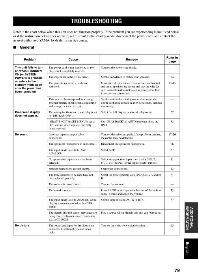
TROUBLESHOOTING
79
En
glish
AD
DIT
ION
AL
IN
FO
RM
AT
ION
Refer to the chart below when this unit does not function properly. If the problem you are experiencing is not listed below or if the instruction below does not help, set this unit to the standby mode, disconnect the power cord, and contact the nearest authorized YAMAHA dealer or service center.
General
TROUBLESHOOTING
Problem Cause RemedyRefer to
page
This unit fails to turn on when STANDBY/ON (or SYSTEM POWER) is pressed, or enters in the standby mode soon after the power has been turned on.
The power cord is not connected or the plug is not completely inserted.
Connect the power cord firmly. —
The impedance setting is incorrect. Set the impedance to match your speakers. 24
The protection circuitry has been activated.
Make sure all speaker wire connections on this unit and on all speakers are secure and that the wire for each connection does not touch anything other than its respective connection.
13-15
This unit has been exposed to a strong external electric shock (such as lightning and strong static electricity).
Set this unit in the standby mode, disconnect the power cord, plug it back in after 30 seconds, then use it normally.
—
On-screen display does not appear.
The setting for the on-screen display is set to “DISPLAY OFF”.
Select the full display or short display mode. 52
“GRAY BACK” in SET MENU is set to OFF, and no video signal is currently being received.
Set “GRAY BACK” to AUTO to always show the OSD.
63
No sound Incorrect input or output cable connections.
Connect the cables properly. If the problem persists, the cables may be defective.
17-20
The optimizer microphone is connected. Disconnect the optimizer microphone. 26
The input mode is set to DTS or ANALOG.
Select AUTO. 37
No appropriate input source has been selected.
Select an appropriate input source with INPUT, MULTI CH INPUT or the input selector buttons.
31
Speaker connections are not secure. Secure the connections. 13
The front speakers to be used have not been selected properly.
Select the front speakers with SPEAKERS A and/or B.
31
The volume is turned down. Turn up the volume. —
The sound is muted. Press MUTE or any operation buttons of this unit to cancel a mute and adjust the volume.
32
The input mode is set to ANALOG while playing a source encoded with a DTS signal.
Set the input mode to AUTO or DTS. 37
The signals this unit cannot reproduce are being received from a source component e.g.: a CD-ROM.
Play a source whose signals this unit can reproduce. —
No picture The output and input for the picture are connected to different types of video jacks.
Turn on the video conversion function. 63
01EN_00_RXV750_GB.book Page 79 Thursday, February 12, 2004 5:15 PM
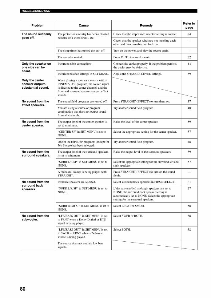
80
TROUBLESHOOTING
Problem Cause RemedyRefer to
page
The sound suddenly goes off.
The protection circuitry has been activated because of a short circuit, etc.
Check that the impedance selector setting is correct. 24
Check that the speaker wires are not touching each other and then turn this unit back on.
—
The sleep timer has turned the unit off. Turn on the power, and play the source again. —
The sound is muted. Press MUTE to cancel a mute. 32
Only the speaker on one side can be heard.
Incorrect cable connections. Connect the cables properly. If the problem persists, the cables may be defective.
13
Incorrect balance settings in SET MENU. Adjust the SPEAKER LEVEL settings. 59
Only the center speaker outputs substantial sound.
When playing a monaural source with a CINEMA DSP program, the source signal is directed to the center channel, and the front and surround speakers output effect sounds.
No sound from the effect speakers.
The sound field programs are turned off. Press STRAIGHT (EFFECT) to turn them on. 37
You are using a source or program combination that does not output sound from all channels.
Try another sound field program. 48
No sound from the center speaker.
The output level of the center speaker is set to minimum.
Raise the level of the center speaker. 59
“CENTER SP” in SET MENU is set to NONE.
Select the appropriate setting for the center speaker. 57
One of the HiFi DSP programs (except for 7ch Stereo) has been selected.
Try another sound field program. 48
No sound from the surround speakers.
The output level of the surround speakers is set to minimum.
Raise the output level of the surround speakers. 59
“SURR L/R SP” in SET MENU is set to NONE.
Select the appropriate setting for the surround left and right speakers.
57
A monaural source is being played with STRAIGHT.
Press STRAIGHT (EFFECT) to turn on the sound fields.
—
No sound from the surround back speakers.
Presence speakers are selected. Select surround back speakers in PR/SB SELECT. 61
“SURR L/R SP” in SET MENU is set to NONE.
If the surround left and right speakers are set to NONE, the surround back speaker setting is automatically set to NONE. Select the appropriate setting for the surround speakers.
57
“SURR B L/R SP” in SET MENU is set to NONE.
Select LRGx1 or SMLx1. 58
No sound from the subwoofer.
“LFE/BASS OUT” in SET MENU is set to FRNT when a Dolby Digital or DTS signal is being played.
Select SWFR or BOTH. 58
“LFE/BASS OUT” in SET MENU is set to SWFR or FRNT when a 2-channel source is being played.
Select BOTH. 58
The source does not contain low bass signals.
01EN_00_RXV750_GB.book Page 80 Thursday, February 12, 2004 5:15 PM
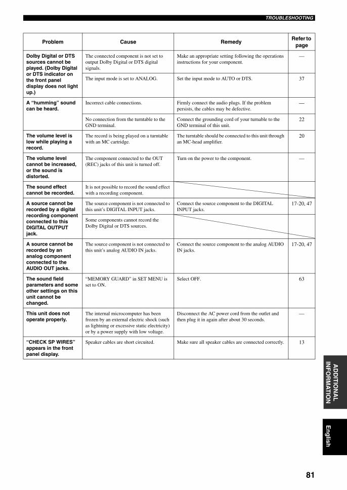
81
En
glish
TROUBLESHOOTINGA
DD
ITIO
NA
L
INF
OR
MA
TIO
N
Problem Cause RemedyRefer to
page
Dolby Digital or DTS sources cannot be played. (Dolby Digital or DTS indicator on the front panel display does not light up.)
The connected component is not set to output Dolby Digital or DTS digital signals.
Make an appropriate setting following the operations instructions for your component.
—
The input mode is set to ANALOG. Set the input mode to AUTO or DTS. 37
A “humming” sound can be heard.
Incorrect cable connections. Firmly connect the audio plugs. If the problem persists, the cables may be defective.
—
No connection from the turntable to the GND terminal.
Connect the grounding cord of your turnable to the GND terminal of this unit.
22
The volume level is low while playing a record.
The record is being played on a turntable with an MC cartridge.
The turntable should be connected to this unit through an MC-head amplifier.
20
The volume level cannot be increased, or the sound is distorted.
The component connected to the OUT (REC) jacks of this unit is turned off.
Turn on the power to the component. —
The sound effect cannot be recorded.
It is not possible to record the sound effect with a recording component.
A source cannot be recorded by a digital recording component connected to this DIGITAL OUTPUT jack.
The source component is not connected to this unit’s DIGITAL INPUT jacks.
Connect the source component to the DIGITAL INPUT jacks.
17-20, 47
Some components cannot record the Dolby Digital or DTS sources.
A source cannot be recorded by an analog component connected to the AUDIO OUT jacks.
The source component is not connected to this unit’s analog AUDIO IN jacks.
Connect the source component to the analog AUDIO IN jacks.
17-20, 47
The sound field parameters and some other settings on this unit cannot be changed.
“MEMORY GUARD” in SET MENU is set to ON.
Select OFF. 63
This unit does not operate properly.
The internal microcomputer has been frozen by an external electric shock (such as lightning or excessive static electricity) or by a power supply with low voltage.
Disconnect the AC power cord from the outlet and then plug it in again after about 30 seconds.
—
“CHECK SP WIRES” appears in the front panel display.
Speaker cables are short circuited. Make sure all speaker cables are connected correctly. 13
01EN_00_RXV750_GB.book Page 81 Thursday, February 12, 2004 5:15 PM
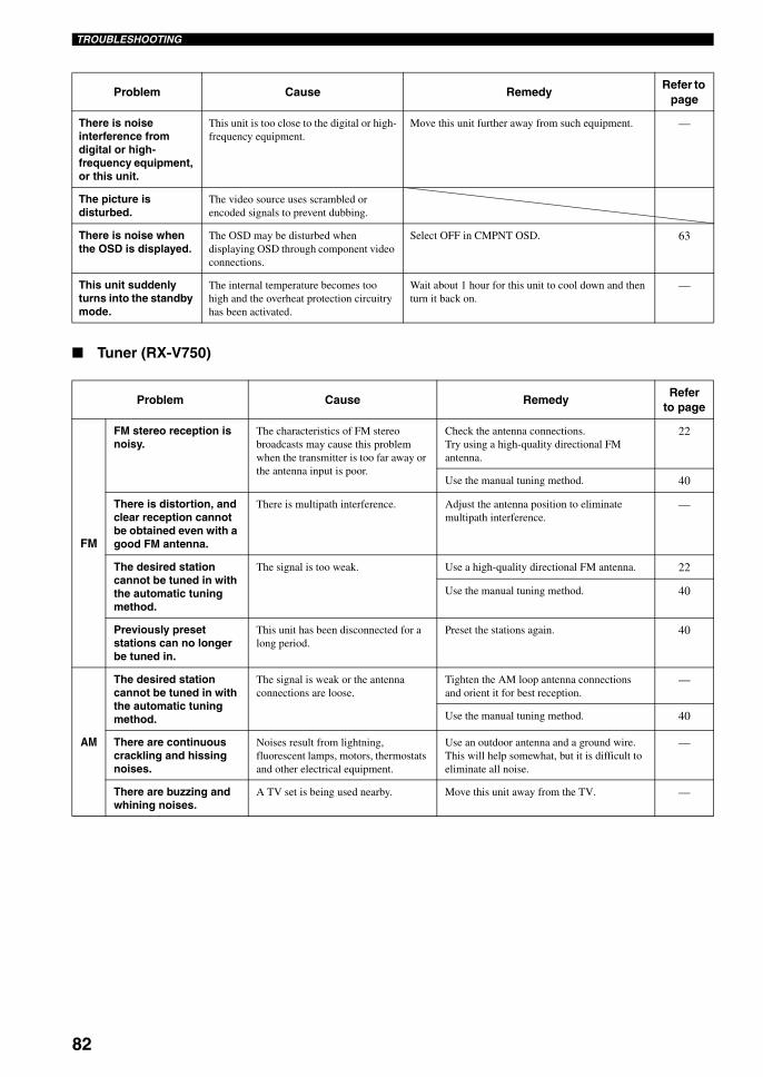
82
TROUBLESHOOTING
Tuner (RX-V750)
Problem Cause RemedyRefer to
page
There is noise interference from digital or high-frequency equipment, or this unit.
This unit is too close to the digital or high-frequency equipment.
Move this unit further away from such equipment. —
The picture is disturbed.
The video source uses scrambled or encoded signals to prevent dubbing.
There is noise when the OSD is displayed.
The OSD may be disturbed when displaying OSD through component video connections.
Select OFF in CMPNT OSD. 63
This unit suddenly turns into the standby mode.
The internal temperature becomes too high and the overheat protection circuitry has been activated.
Wait about 1 hour for this unit to cool down and then turn it back on.
—
Problem Cause RemedyRefer
to page
FM
FM stereo reception is noisy.
The characteristics of FM stereo broadcasts may cause this problem when the transmitter is too far away or the antenna input is poor.
Check the antenna connections.Try using a high-quality directional FM antenna.
22
Use the manual tuning method. 40
There is distortion, and clear reception cannot be obtained even with a good FM antenna.
There is multipath interference. Adjust the antenna position to eliminate multipath interference.
—
The desired station cannot be tuned in with the automatic tuning method.
The signal is too weak. Use a high-quality directional FM antenna. 22
Use the manual tuning method. 40
Previously preset stations can no longer be tuned in.
This unit has been disconnected for a long period.
Preset the stations again. 40
AM
The desired station cannot be tuned in with the automatic tuning method.
The signal is weak or the antenna connections are loose.
Tighten the AM loop antenna connections and orient it for best reception.
—
Use the manual tuning method. 40
There are continuous crackling and hissing noises.
Noises result from lightning, fluorescent lamps, motors, thermostats and other electrical equipment.
Use an outdoor antenna and a ground wire. This will help somewhat, but it is difficult to eliminate all noise.
—
There are buzzing and whining noises.
A TV set is being used nearby. Move this unit away from the TV. —
01EN_00_RXV750_GB.book Page 82 Thursday, February 12, 2004 5:15 PM
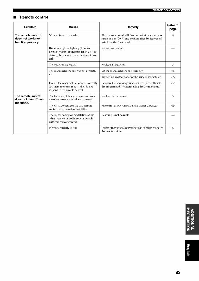
83
En
glish
TROUBLESHOOTINGA
DD
ITIO
NA
L
INF
OR
MA
TIO
N
Remote control
Problem Cause RemedyRefer to
page
The remote control does not work nor function properly.
Wrong distance or angle. The remote control will function within a maximum range of 6 m (20 ft) and no more than 30 degrees off-axis from the front panel.
8
Direct sunlight or lighting (from an inverter type of fluorescent lamp, etc.) is striking the remote control sensor of this unit.
Reposition this unit. —
The batteries are weak. Replace all batteries. 3
The manufacturer code was not correctly set.
Set the manufacturer code correctly. 66
Try setting another code for the same manufacturer. 66
Even if the manufacturer code is correctly set, there are some models that do not respond to the remote control.
Program the necessary functions independently into the programmable buttons using the Learn feature.
69
The remote control does not “learn” new functions.
The batteries of this remote control and/or the other remote control are too weak.
Replace the batteries. 3
The distance between the two remote controls is too much or too little.
Place the remote controls at the proper distance. 69
The signal coding or modulation of the other remote control is not compatible with this remote control.
Learning is not possible. —
Memory capacity is full. Delete other unnecessary functions to make room for the new functions.
72
01EN_00_RXV750_GB.book Page 83 Thursday, February 12, 2004 5:15 PM
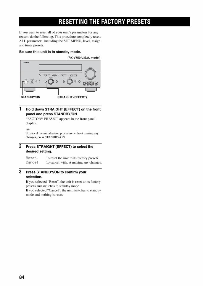
RESETTING THE FACTORY PRESETS
84
If you want to reset all of your unit’s parameters for any reason, do the following. This procedure completely resets ALL parameters, including the SET MENU, level, assign and tuner presets.
Be sure this unit is in standby mode.
1 Hold down STRAIGHT (EFFECT) on the front panel and press STANDBY/ON.“FACTORY PRESET” appears in the front panel display.
yTo cancel the initialization procedure without making any changes, press STANDBY/ON.
2 Press STRAIGHT (EFFECT) to select the desired setting.
Reset To reset the unit to its factory presets.Cancel To cancel without making any changes.
3 Press STANDBY/ON to confirm your selection.If you selected “Reset”, the unit is reset to its factory presets and switches to standby mode.If you selected “Cancel”, the unit switches to standby mode and nothing is reset.
RESETTING THE FACTORY PRESETS
AUTO/MAN'L MONO
S VIDEO VIDEO OPTICALL AUDIO R
MAN'L/AUTO FMLEVELNEXTEDIT
EFFECT
MEMORYFM/AMPRESET/TUNINGOPTIMIZER
MIC A/B/C/D/E
PROGRAM
l PRESET/TUNING h TUNING MODE
PURE DIRECTINPUT MODETONE CONTROLSTRAIGHTSPEAKERSPHONES
SILENT CINEMA
STANDBY/ON
BAMULTI CH
INPUT
VOLUME
VIDEO AUX
INPUT
STANDBY/ON STRAIGHT (EFFECT)
(RX-V750 U.S.A. model)
01EN_00_RXV750_GB.book Page 84 Thursday, February 12, 2004 5:15 PM
GLOSSARY
85
En
glish
AD
DIT
ION
AL
IN
FO
RM
AT
ION
Dolby DigitalDolby Digital is a digital surround sound system that gives you completely independent multi-channel audio. With 3 front channels (left, center, and right), and 2 surround stereo channels, Dolby Digital provides 5 full-range audio channels. With an additional channel especially for bass effects, called LFE (low frequency effect), the system has a total of 5.1-channels (LFE is counted as 0.1 channel). By using 2-channel stereo for the surround speakers, more accurate moving sound effects and surround sound environment are possible than with Dolby Surround. The wide dynamic range (from maximum to minimum volume) reproduced by the 5 full-range channels and the precise sound orientation generated using digital sound processing provide listeners with previously unheard of excitement and realism.With this unit, any sound environment from monaural up to a 5.1-channel configuration can be freely selected for your enjoyment.
Dolby Digital Surround EXDolby Digital EX creates 6 full-bandwidth output channels from 5.1-channel sources. This is done using a matrix decoder that derives 3 surround channels from the 2 in the original recording. For the best results, Dolby Digital EX should be used with movie sound tracks recorded with Dolby Digital Surround EX. With this additional channel, you can experience more dynamic and realistic moving sound especially with scenes with “flyover” and “fly-around” effects.
Dolby Pro Logic IIDolby Pro Logic II is an improved technique used to decode vast numbers of existing Dolby Surround software. This new technology enables a discrete 5-channel playback with 2 front left and right channels, 1 center channel, and 2 surround left and right channels (instead of only 1 surround channel for conventional Pro Logic technology). Music and Game modes are also available for 2-channel sources in addition to the Movie mode.
Dolby Pro Logic IIxDolby Pro Logic IIx is a new technology enabling discrete multi-channel playback from 2-channel or multi-channel sources. There is a Music mode for music, a Movie mode for movies and a Game mode for games.
Dolby SurroundDolby Surround uses a 4 channel analog recording system to reproduce realistic and dynamic sound effects: 2 front left and right channels (stereo), a center channel for dialog (monaural), and a surround channel for special sound effects (monaural). The surround channel reproduces sound within a narrow frequency range.Dolby Surround is widely used with nearly all video tapes and laser discs, and in many TV and cable broadcasts as well. The Dolby Pro Logic decoder built into this unit employs a digital signal processing system that automatically stabilizes the volume on each channel to enhance moving sound effects and directionality.
DTS 96/24DTS 96/24 offers an unprecedented level of audio quality for multi-channel sound on DVD-Video, and is fully backward-compatible with all DTS decoders. “96” refers to a 96 kHz sampling rate (compared to the typical 48 kHz sampling rate). “24” refers to 24-bit word length. DTS 96/24 offers sound quality transparent to the original 96/24 master, and 96/24 5.1-channel sound with full-quality full-motion video for music programs and motion picture soundtracks on DVD-video.
DTS (Digital Theater Systems)Digital Surround
DTS digital surround was developed to replace the analog soundtracks of movies with a 6-channel digital sound track, and is now rapidly gaining popularity in movie theaters around the world. Digital Theater Systems Inc. has developed a home theater system so that you can enjoy the depth of sound and natural spatial representation of DTS digital surround in your home. This system produces practically distortion-free 6-channel sound (technically, a left, right and center channels, 2 surround channels, plus an LFE 0.1 channel as a subwoofer, for a total of 5.1-channels). The unit incorporates DTS-ES decoder that enables 6.1- channel reproduction by adding the surround back channel to existing 5.1-channel format.
Neo:6Neo:6 decodes the conventional 2-channel sources for 6 channel playback by the specific decoder. It enables playback with the full-range channels with higher separation just like digital discrete signal playback. Two modes are available; “Music mode” for playing music sources and “Cinema mode” for movies.
GLOSSARY
Audio formats
01EN_00_RXV750_GB.book Page 85 Thursday, February 12, 2004 5:15 PM
86
GLOSSARY
CINEMA DSPSince the Dolby Surround and DTS systems were originally designed for use in movie theaters, their effect is best felt in a theater having many speakers and designed for acoustic effects. Since home conditions, such as room size, wall material, number of speakers, and so on, can differ so widely, it’s inevitable that there are differences in the sound heard as well. Based on a wealth of actually measured data, YAMAHA CINEMA DSP uses YAMAHA original sound field technology to combine Dolby Pro Logic, Dolby Digital and DTS systems to provide the visual and audio experience of movie theater in the listening room of your own home.
SILENT CINEMAYAMAHA has developed a natural, realistic sound effect DSP algorithm for headphones.Parameters for headphones have been set for each sound field so that accurate representations of all the sound field programs can be enjoyed on headphones.
Virtual CINEMA DSPYAMAHA has developed a Virtual CINEMA DSP algorithm that allows you to enjoy DSP sound field surround effects even without any surround speakers by using virtual surround speakers.It is even possible to enjoy Virtual CINEMA DSP using a minimal two-speaker system that does not include a center speaker.
ITU-RITU-R is the radio communication sector of the ITU (International Telecommunication Union). ITU-R recommends a standard speaker placement which is used in many critical listening rooms, especially for mastering purposes.
LFE 0.1 channelThis channel is for the reproduction of low bass signals. The frequency range for this channel is 20 Hz to 120 Hz. This channel is counted as 0.1 because it only enforces a low frequency range compared to the full-range reproduced by the other 5/6 channels in Dolby Digital or DTS 5.1/6.1-channel systems.
PCM (Linear PCM)Linear PCM is a signal format under which an analog audio signal is digitized, recorded and transmitted without using any compression. This is used as a method of recording CDs and DVD audio. The PCM system uses a technique for sampling the size of the analog signal per very small unit of time. Standing for “pulse code modulation”, the analog signal is encoded as pulses and then modulated for recording.
Sampling frequency and number of quantized bits
When digitizing an analog audio signal, the number of times the signal is sampled per second is called the sampling frequency, while the degree of fineness when converting the sound level into a numeric value is called the number of quantized bits.The range of rates that can be played back is determined based on the sampling rate, while the dynamic range representing the sound level difference is determined by the number of quantized bits. In principle, the higher the sampling frequency, the wider the range of frequencies that can be played back, and the higher the number of quantized bits, the more finely the sound level can be reproduced.
Sound field programs Audio information
01EN_00_RXV750_GB.book Page 86 Thursday, February 12, 2004 5:15 PM
87
En
glish
GLOSSARYA
DD
ITIO
NA
L
INF
OR
MA
TIO
N
Component video signalWith the component video signal system, the video signal is separated into the Y signal for the luminance and the PB and PR signals for the chrominance. Color can be reproduced more faithfully with this system because each of these signals is independent. The component signal is also called the “color difference signal” because the luminance signal is subtracted from the color signal.A monitor with component input jacks is required in order to use the component signal for output.
Composite video signalWith the composite video signal system, the video signal is composed of three basic elements of a video picture; color, brightness and synchronization data. A composite video jack on a video component transmits these three elements combined.
S-Video signalWith the S-Video signal system, the video signal normally transmitted using a pin cable is separated and transmitted as the Y signal for the luminance and the C signal for the chrominance through the S-Video cable. Using the S VIDEO jack eliminates video signal transmission loss and allows recording and playback of even more beautiful images.
Video signal information
01EN_00_RXV750_GB.book Page 87 Thursday, February 12, 2004 5:15 PM
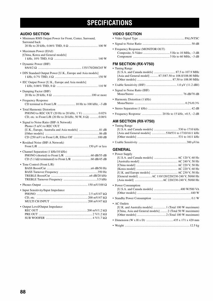
SPECIFICATIONS
88
AUDIO SECTION• Minimum RMS Output Power for Front, Center, Surround,
Surround back20 Hz to 20 kHz, 0.06% THD, 8 Ω ..................................... 100 W
• Maximum Power (EIAJ)[China, Korea and General models]
1 kHz, 10% THD, 8 Ω ........................................................ 140 W
• Dynamic Power (IHF)8/6/4/2 Ω ........................................................ 135/170/200/245 W
• DIN Standard Output Power [U.K., Europe and Asia models]1 kHz, 0.7% THD, 4 Ω ....................................................... 150 W
• IEC Output Power [U.K., Europe and Asia models]1 kHz, 0.06% THD, 8 Ω ..................................................... 110 W
• Damping Factor (IHF)20 Hz to 20 kHz, 8 Ω ..................................................100 or more
• Frequency ResponseCD terminal to Front L/R ....................... 10 Hz to 100 kHz, –3 dB
• Total Harmonic DistortionPHONO to REC OUT (20 Hz to 20 kHz, 1 V) ....................0.02%CD, etc. to Front L/R (20 Hz to 20 kHz, 50 W, 8 Ω) ...........0.06%
• Signal to Noise Ratio (IHF-A Network)Phono (5 mV) to REC OUT[U.K., Europe, Australia and Asia models] ..........................81 dB[Other models] ......................................................................86 dBCD (250 mV) to Front L/R, Effect Off ...............................100 dB
• Residual Noise (IHF-A Network)Front L/R .................................................................150 µV or less
• Channel Separation (1 kHz/10 kHz)PHONO (shorted) to Front L/R .................................60 dB/55 dBCD (5.1 kΩ terminated) to Front L/R ........................60 dB/45 dB
• Tone Control (Front L/R)BASS Boost/Cut .........................................................±6 dB/50 HzBASS Turnover Frequency .................................................350 HzTREBLE Boost/Cut .................................................±6 dB/20 kHzTREBLE Turnover Frequency ...........................................3.5 kHz
• Phones Output ........................................................... 150 mV/100 Ω
• Input Sensitivity/Input ImpedancePHONO ................................................................... 2.5 mV/47 kΩCD, etc. .................................................................. 200 mV/47 kΩMULTI CH INPUT ................................................ 200 mV/47 kΩ
• Output Level/Output ImpedanceREC OUT .............................................................. 200 mV/1.2 kΩPRE OUT ..................................................................... 2 V/1.2 kΩSUB WOOFER ............................................................ 4 V/1.7 kΩ
VIDEO SECTION• Video Signal Type ........................................................... PAL/NTSC
• Signal to Noise Ratio ............................................................... 50 dB
• Frequency Response (MONITOR OUT)Composite, S-Video .................................. 5 Hz to 10 MHz, –3 dBComponent ............................................... 5 Hz to 60 MHz, –3 dB
FM SECTION (RX-V750)• Tuning Range
[U.S.A. and Canada models] ........................... 87.5 to 107.9 MHz[Asia and General model] .......... 87.5/87.50 to 108.0/108.00 MHz[Other models] ............................................. 87.50 to 108.00 MHz
• Usable Sensitivity (IHF) ....................................... 1.0 µV (11.2 dBf)
• Signal to Noise Ratio (IHF)Mono/Stereo .............................................................. 76 dB/70 dB
• Harmonic Distortion (1 kHz)Mono/Stereo ................................................................. 0.2%/0.3%
• Stereo Separation (1 kHz) ........................................................ 42 dB
• Frequency Response .......................... 20 Hz to 15 kHz, +0.5, –2 dB
AM SECTION (RX-V750)• Tuning Range
[U.S.A. and Canada models] ............................... 530 to 1710 kHz[Asia and General models] ..................530/531 to 1710/1611 kHz[Other models] ..................................................... 531 to 1611 kHz
• Usable Sensitivity ..............................................................300 µV/m
GENERAL• Power Supply
[U.S.A. and Canada models] .............................. AC 120 V, 60 Hz[Australia model] ................................................ AC 240 V, 50 Hz[China model] ..................................................... AC 220 V, 50 Hz[Korea model] ..................................................... AC 220 V, 60 Hz[U.K. and Europe models] .................................. AC 230 V, 50 Hz[General model] .................AC 110/120/220/230-240 V, 50/60 Hz[Asia model] ....................................AC 220/230-240 V, 50/60 Hz
• Power Consumption[U.S.A. and Canada models] ..................................400 W/500 VA[Other models] ..................................................................... 440 W
• Standby Power Consumption .................................................. 0.1 W
• AC Outlets[U.K. and Australia models] ................ 1 (Total 100 W maximum)[China, Asia and General models] ......... 2 (Total 50 W maximum)[Other models] ..................................... 2 (Total 100 W maximum)
• Dimension (W x H x D) ...................................435 x 171 x 420 mm
• Weight ....................................................................................12.5 kg
SPECIFICATIONS
01EN_00_RXV750_GB.book Page 88 Thursday, February 12, 2004 5:15 PM

YAMAHA ELECTRONICS CORPORATION, USA 6660 ORANGETHORPE AVE., BUENA PARK, CALIF. 90620, U.S.A.YAMAHA CANADA MUSIC LTD. 135 MILNER AVE., SCARBOROUGH, ONTARIO M1S 3R1, CANADAYAMAHA ELECTRONIK EUROPA G.m.b.H. SIEMENSSTR. 22-34, 25462 RELLINGEN BEI HAMBURG, F.R. OF GERMANYYAMAHA ELECTRONIQUE FRANCE S.A. RUE AMBROISE CROIZAT BP70 CROISSY-BEAUBOURG 77312 MARNE-LA-VALLEE CEDEX02, FRANCEYAMAHA ELECTRONICS (UK) LTD. YAMAHA HOUSE, 200 RICKMANSWORTH ROAD WATFORD, HERTS WD18 7GQ, ENGLANDYAMAHA SCANDINAVIA A.B. J A WETTERGRENS GATA 1, BOX 30053, 400 43 VÄSTRA FRÖLUNDA, SWEDENYAMAHA MUSIC AUSTRALIA PTY, LTD. 17-33 MARKET ST., SOUTH MELBOURNE, 3205 VIC., AUSTRALIA
© 2004 All rights reserved.
Printed in Malaysia WC85520
RX-V750 AV Receiver
DSP-AX750SE AV Amplifier
OWNER’S MANUALMODE D’EMPLOI
BEDIENUNGSANLEITUNGBRUKSANVISNING
MANUALE DI ISTRUZIONIMANUAL DE INSTRUCCIONES
GEBRUIKSAANWIJZING
GB
RX-V750/DSP-AX750SE
RXV750_RDS_cv.fm Page 1 Wednesday, January 21, 2004 11:44 AM