RV3 Series DS
55
JIS symbol Compact rotary actuator with vane mechanism/standard RV3 Series Torque: 1/3/10/20/30 Oscillating angle: 90°, 180°, 270° Item RV3S Size 1 3 10 20 30 Effective torque N·m 0.12 0.31 0.98 1.70 3.19 Actuation Single vane Working fluid Compressed air Max. working pressure MPa 0.7 (≈100 psi, 7 bar) 1.0 (≈150 psi, 10 bar) Min. working pressure MPa 0.2 (≈29 psi, 2 bar) Proof pressure MPa 1.05 (≈150 psi, 10.5 bar) 1.5 (≈220 psi, 15 bar) Ambient temperature °C -5 (23°F) to 80 (176°F) *3 -5 (23°F) to 60 (140°F) Port size M5 Rc1/8 Oscillating angle tolerance ° 90 +4 0 180 +4 0 270 +4 0 90 +4 0 180 +4 0 270 +4 0 90 +4 0 180 +4 0 270 +4 0 90 +4 0 180 +4 0 270 +4 0 90 +3 0 180 +3 0 270 +3 0 Oscillating origin ° 45, 90 45 45, 90 45 45, 90 45 45, 90 45 45 Allowable absorbed energy *1 mJ 0.6 1.5 3 15 25 Max. operating frequency *2 cycle/min 300 180 96 240 150 60 240 150 90 210 120 84 180 90 60 Volumetric capacity cm 3 1.4 1.4 1.5 3.4 4 9.8 12 17 21 37 43 Allowable radial load N 30 40 50 300 400 Allowable thrust load N 3 4 25 30 Weight kg 0.036 0.07 0.14 0.25 0.47 0.46 Switch unit weight kg - 0.04 0.04 0.05 0.05 Lubrication Not required (use turbine oil class 1 ISO VG32 if necessary for lubrication) Item RV3D Size 1 3 10 20 30 Effective torque N·m 0.28 0.71 2.11 3.88 7.70 Actuation Double vane Working fluid Compressed air Max. working pressure MPa 0.7 (≈100 psi, 7 bar) 1.0 (≈150 psi, 10 bar) Min. working pressure MPa 0.2 (≈29 psi, 2 bar) Proof pressure MPa 1.05 (≈150 psi, 10.5 bar) 1.5 (≈220 psi, 15 bar) Ambient temperature °C -5 (23°F) to 80 (176°F) *3 -5 (23°F) to 60 (140°F) Port size M5 Rc1/8 Oscillating angle tolerance ° 90 +4 0 90 +3 0 Oscillating origin ° 45 Allowable absorbed energy *1 mJ 0.6 1.5 3 15 25 Max. operating frequency *2 cycle/min 300 240 210 180 Volumetric capacity cm 3 1.1 2.8 8.1 15 34 Allowable radial load N 30 40 50 300 400 Allowable thrust load N 3 4 25 30 Weight kg 0.037 0.072 0.14 0.26 0.48 Switch unit weight kg - 0.04 0.04 0.05 0.05 Lubrication Not required (use turbine oil ISO VG32 if necessary for lubrication) *1 : Calculate the allowable energy with allowable inertia energy of the shaft of the rotary actuator as follows. (Allowable energy) ≥ 1/2Iω 2 x 10 3 (refer to page 1398 for details.) *2 : The max. operating frequency is at a supply pressure of 0.5 MPa [without load]. *3 : 5 to 60°C when switch is provided. *4 : A key is attached with the rotary actuator with keyway. *5 : Contact CKD for products other than standard specifications. Double vane mechanism Single vane mechanism Specifications S D LCM LCR LCG LCW LCX STM STG STS/STL STR2 UCA2 ULK* JSK/M2 JSG JSC3/JSC4 USSD UFCD USC UB JSB3 LMB LML HCM HCA LBC CAC4 UCAC2 CAC-N UCAC-N RCS2 RCC2 PCC SHC MCP GLC MFC BBS RRC GRC RV3* NHS HRL LN Hand Chuk MecHnd/Chuk ShkAbs FJ FK SpdContr Ending 1338
Transcript of RV3 Series DS

JIS symbol
Compact rotary actuator with vane mechanism/standard
RV3 Series Torque: 1/3/10/20/30 Oscillating angle: 90°, 180°, 270°
Item RV3SSize 1 3 10 20 30Effective torque N·m 0.12 0.31 0.98 1.70 3.19Actuation Single vaneWorking fluid Compressed airMax. working pressure MPa 0.7 (≈100 psi, 7 bar) 1.0 (≈150 psi, 10 bar)Min. working pressure MPa 0.2 (≈29 psi, 2 bar)Proof pressure MPa 1.05 (≈150 psi, 10.5 bar) 1.5 (≈220 psi, 15 bar)Ambient temperature °C -5 (23°F) to 80 (176°F) *3 -5 (23°F) to 60 (140°F)Port size M5 Rc1/8Oscillating angle tolerance ° 90+4
0 180+40 270+4
0 90+40 180+4
0 270+40 90+4
0 180+40 270+4
0 90+40 180+4
0 270+40 90+3
0 180+30 270+3
0
Oscillating origin ° 45, 90 45 45, 90 45 45, 90 45 45, 90 45 45Allowable absorbed energy *1 mJ 0.6 1.5 3 15 25Max. operating frequency *2 cycle/min 300 180 96 240 150 60 240 150 90 210 120 84 180 90 60Volumetric capacity cm3 1.4 1.4 1.5 3.4 4 9.8 12 17 21 37 43Allowable radial load N 30 40 50 300 400Allowable thrust load N 3 4 25 30Weight kg 0.036 0.07 0.14 0.25 0.47 0.46Switch unit weight kg - 0.04 0.04 0.05 0.05Lubrication Not required (use turbine oil class 1 ISO VG32 if necessary for lubrication)
Item RV3DSize 1 3 10 20 30Effective torque N·m 0.28 0.71 2.11 3.88 7.70Actuation Double vaneWorking fluid Compressed airMax. working pressure MPa 0.7 (≈100 psi, 7 bar) 1.0 (≈150 psi, 10 bar)Min. working pressure MPa 0.2 (≈29 psi, 2 bar)Proof pressure MPa 1.05 (≈150 psi, 10.5 bar) 1.5 (≈220 psi, 15 bar)Ambient temperature °C -5 (23°F) to 80 (176°F) *3 -5 (23°F) to 60 (140°F)Port size M5 Rc1/8Oscillating angle tolerance ° 90+4
0 90+30
Oscillating origin ° 45Allowable absorbed energy *1 mJ 0.6 1.5 3 15 25Max. operating frequency *2 cycle/min 300 240 210 180Volumetric capacity cm3 1.1 2.8 8.1 15 34Allowable radial load N 30 40 50 300 400Allowable thrust load N 3 4 25 30Weight kg 0.037 0.072 0.14 0.26 0.48Switch unit weight kg - 0.04 0.04 0.05 0.05Lubrication Not required (use turbine oil ISO VG32 if necessary for lubrication)
*1 : Calculate the allowable energy with allowable inertia energy of the shaft of the rotary actuator as follows.(Allowable energy) ≥ 1/2Iω2 x 103 (refer to page 1398 for details.)
*2 : The max. operating frequency is at a supply pressure of 0.5 MPa [without load].*3 : 5 to 60°C when switch is provided.*4 : A key is attached with the rotary actuator with keyway.*5 : Contact CKD for products other than standard specifications.
Double vane mechanism
Single vane mechanism
Specifications
SD
LCMLCRLCGLCWLCXSTMSTGSTS/STLSTR2UCA2ULK*JSK/M2JSGJSC3/JSC4USSDUFCDUSCUBJSB3LMBLMLHCMHCALBCCAC4UCAC2CAC-NUCAC-NRCS2RCC2PCCSHCMCPGLCMFCBBSRRCGRCRV3*NHSHRLLNHandChukMecHnd/ChukShkAbsFJFKSpdContr
Ending
1338

RV3 SeriesSpecifications/operational principle
S D
* mark indicates a rotary actuator size. (3, 10, 20, 30)
Switch specifications
Operational principle Double vane1. Configured with two vanes sliding on the internal body surface,
integrated shaft, and two shoes (stoppers).2. Air from port A pushes vane, goes through passage in shaft,
pushes another vane, turns shaft, and finally generates torque.3. Rotates in the same way as the single vane.
Single vane1. Configured with vane sliding on the internal body surface,
integrated shaft, and shoe (stopper).2. Air from port A pushes vane, rotates shaft, and generates
torque.3. Air in opposite chamber is exhausted from port B, and the shaft
rotates clockwise.4. Vane stops when it contacts the shoe.5. Air supply from port B causes counterclockwise rotation in the
same manner.
ItemProximity switch
SR-* (-U)Applications For programmable controller/relay/IC circuit/compact solenoid valveOutput method NPN outputPower supply voltage 5 VDC to 30 VDCLoad voltage/current 5 to 30 VDC, 200 mA or lessCurrent consumption 20 mA or less with 24 VDCInternal voltage drop 1.5 V or lessIndicator lamp LED (Lit when ON)Leakage current 10 μA or lessLead wire length 1 m (oil resistant vinyl cabtyre cable 4-conductor 0.2 mm2)Shock resistance 490 m/s2
Insulation resistance 100 MΩ or more with 500 V meggerWithstand voltage No failure after 1 minute of 1,000 VAC application.Ambient temperature 5 to 60°CDegree of protection IEC standards IP67, JIS C0920 (water tight)
Shoe
Vane
Body
Shaft
ABAB
Vane
Shoe
B A
Body
Shaft
AB
LCMLCRLCGLCWLCXSTMSTGSTS/STLSTR2UCA2ULK*JSK/M2JSGJSC3/JSC4USSDUFCDUSCUBJSB3LMBLMLHCMHCALBCCAC4UCAC2CAC-NUCAC-NRCS2RCC2PCCSHCMCPGLCMFCBBSRRCGRCRV3*NHSHRLLNHandChukMecHnd/ChukShkAbsFJFKSpdContr
Ending
1339

RV3 SeriesS D
SR-U453RV3S FA90
Model No.A
Oscillating angleC
SwitchE
Option (*1, *2)
F
Nominal sizeB
How to order Compact rotary actuator (standard) RV3*
[Example of model No.]RV3S3-90-45-SR-U-FAModel: Compact rotary actuatorA Model No. : Single vane mechanism RV3SB Nominal size : 3C Oscillating angle : 90°D Oscillating origin : 45°E Switch : With radial lead wire switchF Option : With flange bracket
[Example of model No.]RV3S-SR-3-90-45-UModel: Switch unit A Model : For RV3S3B Oscillating angle : 90°C Oscillating origin : 45°D Lead wire outlet direction
: Radial lead wire
USR-3 4590 How to order switch unit
*1 : The type with switch is not available for the axial port position direction “S”.
*2 : The mounting bracket (FA, LS) is attached at shipment. Refer to pages 1348 and 1349 for dimensions.
Precautions for model No. selection
Code DescriptionA ModelSR-3 Applicable actuator: RV3S
D3 SR-10 Applicable actuator: RV3S
D 10 SR-20 Applicable actuator: RV3S
D20 SR-30 Applicable actuator: RV3S
D30
B Oscillating angle90 90°180 180°270 270°
C Oscillating originModel SR-3 SR-10 SR-20 SR-30
45 45°
90 90°
D Lead wire directionBlank With axial lead wire switch
U With radial lead wire switch
A Model No.Single vane mechanism Double vane mechanism
RV3S RV3D
Code DescriptionB Nominal size1
Effective torque 0.5 MPa
0.12 N·m 0.27 N·m3 0.31 N·m 0.71 N·m10 0.98 N·m 2.11 N·m20 1.70 N·m 3.88 N·m30 3.19 N·m 7.7 N·m
C Oscillating angle90 90°
180 180°
270 270°
D Oscillating originNominal size 1 3 10 20 30 1 3 10 20 30
45 45°
90 90° (excluding oscillating angle 270°)
E SwitchNominal size 1 3 10 20 30 1 3 10 20 30
Blank Without switch
SR With axial lead wire switch
SR-U With radial lead wire switch
F OptionNominal size 1 3 10 20 30 1 3 10 20 30
Blank No option
S Axial port position
FA With flange bracket
LS With foot bracket
Oscillating originD
RV3S
ModelA
Oscillating angleB
Oscillating originC
Lead wire directionD
LCMLCRLCGLCWLCXSTMSTGSTS/STLSTR2UCA2ULK*JSK/M2JSGJSC3/JSC4USSDUFCDUSCUBJSB3LMBLMLHCMHCALBCCAC4UCAC2CAC-NUCAC-NRCS2RCC2PCCSHCMCPGLCMFCBBSRRCGRCRV3*NHSHRLLNHandChukMecHnd/ChukShkAbsFJFKSpdContr
Ending
1340

SDRV3 Series
Output characteristics, etc.
*1 : Tolerance of oscillating origin is based on mounting screw position.*2 : Deflection of torsion angle between keyway on longer axis side (or cut plane) and
square on shorter axis side within 1.5°.
1. Use oscillating time taking the ranges in the table below as a guide.
Compact rotary actuator
(N·m)Output table (effective torque)
Output characteristics graph (effective torque)
Oscillating origin position
Oscillating time setting
RV3SD20, 30 RV3S
D1 to 10
Oscillating origin 90° RV3S1 to 20
Oscillating origin 45° RV3S
D1 to 30
Model No.Oscillating angle
90° 180° 270°RV3 S
D 1 0.03 to 0.3 0.06 to 0.6 0.09 to 0.9
RV3 S D 3 0.04 to 0.8 0.08 to 1.6 0.12 to 2.4
RV3 S D 10 0.045 to 0.9 0.09 to 1.8 0.135 to 2.7
RV3 S D 20 0.05 to 1.0 0.10 to 2 0.15 to 3
RV3 S D 30 0.07 to 0.7 0.14 to 1.4 0.21 to 2.1
Working pressure (MPa)0.2 0.3 0.4 0.5 0.6 0.7 0.8 0.9 1.0
Model No.
Single vane
RV3S1 -0.04 0.07 -0.10 -0.12 -0.15 -0.18 - - -
RV3S3 0.1 0.17 0.24 0.31 0.38 0.45 - - -
RV3S10 0.35 0.56 0.75 0.98 1.2 1.39 - - -
RV3S20 0.59 0.95 1.33 1.7 2.1 2.49 2.87 3.26 3.68
RV3S30 1.1 1.8 2.5 3.19 4.1 4.8 5.8 6.5 7.2
Double vane
RV3D1 0.10 0.16 0.22 0.28 0.34 0.40 - - -
RV3D3 0.25 0.39 0.54 0.71 0.86 1.01 - - -
RV3D10 0.76 1.17 1.62 2.11 2.54 3.03 - - -
RV3D20 1.4 2.22 3.06 3.88 4.7 5.53 6.33 7.17 8.07
RV3D30 2.7 4.4 6 7.7 9.5 11.2 12.99 14.8 16.6
Oscillating angle 90°
Oscillating angle 90°
Oscillating origin 45°+2°−4°
Oscillating origin 90°+2°−4°
Port position Port position
Oscillating angle 180°
Oscillating angle 270°Oscillating angle 180°
RV3D1RV3S1
RV3S3
RV3S10RV3D3
RV3D10
Working pressure (MPa)
4
3.5
3
2.5
2
1.5
1
0.5
10.500
RV3S20
RV3D20RV3S30
RV3D30
Working pressure (MPa)
10.50
18
16
14
12
10
8
6
4
2
0
Out
put (
N·m
)
Out
put (
N·m
)
LCMLCRLCGLCWLCXSTMSTGSTS/STLSTR2UCA2ULK*JSK/M2JSGJSC3/JSC4USSDUFCDUSCUBJSB3LMBLMLHCMHCALBCCAC4UCAC2CAC-NUCAC-NRCS2RCC2PCCSHCMCPGLCMFCBBSRRCGRCRV3*NHSHRLLNHandChukMecHnd/ChukShkAbsFJFKSpdContr
Ending
1341

RV3 SeriesS D
Internal structure and parts list
RV3D30
RV3D20 RV3D1 to 10
RV3S1 to 30 Oscillating origin: 90°
Refer to page 1393 for the repair parts list.
No. Part name Material No. Part name Material1 Shoe sealant Nitrile rubber 7 Body B Aluminum alloy
2 Shoe Resin 8 O-ring Nitrile rubber
3 Vane shaft Steel + resin + nitrile rubber 9 O-ring Nitrile rubber
4 Bearing Sintering oil impregnated material 10 O-ring Nitrile rubber
5 Mounting bolt Steel 11 Plate Steel
6 Body A Aluminum alloy 12 Stopper pin Steel
RV3S1 to 30 Oscillating origin: 45°
87654321
12
87654321
11987654321 8
5
9 10
11
7321 64
4 5 7 86321
LCMLCRLCGLCWLCXSTMSTGSTS/STLSTR2UCA2ULK*JSK/M2JSGJSC3/JSC4USSDUFCDUSCUBJSB3LMBLMLHCMHCALBCCAC4UCAC2CAC-NUCAC-NRCS2RCC2PCCSHCMCPGLCMFCBBSRRCGRCRV3*NHSHRLLNHandChukMecHnd/ChukShkAbsFJFKSpdContr
Ending
1342

SDRV3 Series
Compact/standardDimensions
RV3 1
Oscillating origin 45°
Oscillating origin 90°
S type (Axial port position)
SD
2-M3 depth 6
3.523
Port2-M5
9.44.8
10
3
16
1.2
20
46
10
26
2-M3 depth 6
Port position
Oscillating angle 270°+40
Oscillating angle 180°+40
Oscillating angle 90°+40
Oscillating origin45°
17°17°
3.5 ø4h7
ø4h7
ø8h8
ø8h8
ø27
ø29
23
Port position
Oscillating origin
Oscillating angle 180°+40
Oscillating angle 90°+40
4.5
8.9
9.6
4.1Port 2-M3
17° 17°90°
3.5
LCMLCRLCGLCWLCXSTMSTGSTS/STLSTR2UCA2ULK*JSK/M2JSGJSC3/JSC4USSDUFCDUSCUBJSB3LMBLMLHCMHCALBCCAC4UCAC2CAC-NUCAC-NRCS2RCC2PCCSHCMCPGLCMFCBBSRRCGRCRV3*NHSHRLLNHandChukMecHnd/ChukShkAbsFJFKSpdContr
Ending
1343
RV3 SeriesS D
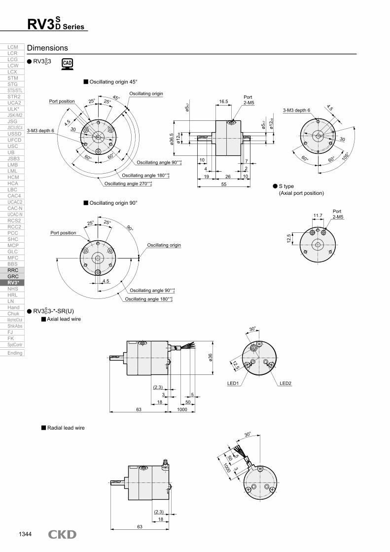
Dimensions RV3 3
Oscillating origin 45°
Oscillating origin 90°
S type (Axial port position)
Radial lead wire
RV 3 3-*-SR(U) Axial lead wire
SD
SD
Port position
3-M3 depth 6
Oscillating angle 270°+40
Oscillating angle 180°+40
Oscillating angle 90°+40
Oscillating origin
3-M3 depth 6
Oscillating angle 180°+40
Oscillating angle 90°+40
Oscillating origin
Port position
Port 2-M5
LED1 LED2(2.3)
318
63
ø36
550
1000
12.5
30°
30°
(2.3)18
63
1000 3550
25° 25°
60° 60°
45°
90°
25°25°
4.530
Port 2-M5
4.5
16.5
10
4
19 26 10
11.7
12.5
27
55
ø36.
5ø1
2 h8
ø5h7
ø5h7
ø12 h
8
4.5
30
105°
60° 60°
LCMLCRLCGLCWLCXSTMSTGSTS/STLSTR2UCA2ULK*JSK/M2JSGJSC3/JSC4USSDUFCDUSCUBJSB3LMBLMLHCMHCALBCCAC4UCAC2CAC-NUCAC-NRCS2RCC2PCCSHCMCPGLCMFCBBSRRCGRCRV3*NHSHRLLNHandChukMecHnd/ChukShkAbsFJFKSpdContr
Ending
1344

SDRV3 Series
Compact/standardDimensions
RV3 10
Radial lead wire
RV 3 10-*-SR(U) Axial lead wire
Oscillating origin 45°
Oscillating origin 90°
S type (Axial port position)
SD
SD
3-M3 depth 6
Oscillating angle 270°+40
Oscillating angle 180°+40
Oscillating angle 90°+40
Oscillating originPort position
3-M3 depth 6
Port position
Oscillating origin
Oscillating angle 180°+40
Oscillating angle 90°+40
25°
12.5
LED1 LED2
1000
550
(2.3)
318.3
81.3
ø42
1000
53
50
(2.3)18.3
81.3
25°
25° 25°12
0°120°
45°
5.5
35
Port 2-M525
14
5
23 40 10
2
7
73
ø42.
5ø1
4 h8
ø6h7
ø6h7
ø14 h
8
60° 60°
35
5.5
25° 25°90°
5.5
Port 2-M513
14
LCMLCRLCGLCWLCXSTMSTGSTS/STLSTR2UCA2ULK*JSK/M2JSGJSC3/JSC4USSDUFCDUSCUBJSB3LMBLMLHCMHCALBCCAC4UCAC2CAC-NUCAC-NRCS2RCC2PCCSHCMCPGLCMFCBBSRRCGRCRV3*NHSHRLLNHandChukMecHnd/ChukShkAbsFJFKSpdContr
Ending
1345

RV3 SeriesS D
Dimensions RV3 20
Oscillating origin 45°
Oscillating origin 90°
S type (Axial port position)
Radial lead wire
RV 3 20-*-SR(U) Axial lead wire
SD
SD
6 0-0.1
25°25°
40
45° Oscillating origin
Oscillating angle 270°+40
Oscillating angle 180°+40
Oscillating angle 90°+40
4-M5 depth 8
Port position 36.5
ø8h7
ø16 h
8
ø49.
53 16
5.5
28.5
7
2
55 10
93.5
ø16 h
8
45°45°
4-M5 depth 840
Keywaywidth 3 -0.004
-0.029 × depth 1.8 +0.10
25° 25°Port position 90°
Oscillating angle 180°+40
Oscillating angle 90°+40
Oscillating origin
16.6
17.8
20°
12.5
LED1 LED2
1000
550
(2.3)2.7
18.3101.8
ø49
1000
53
50
20°
(2.3)18.3101.8
Port 2-M5
Port 2-M5
LCMLCRLCGLCWLCXSTMSTGSTS/STLSTR2UCA2ULK*JSK/M2JSGJSC3/JSC4USSDUFCDUSCUBJSB3LMBLMLHCMHCALBCCAC4UCAC2CAC-NUCAC-NRCS2RCC2PCCSHCMCPGLCMFCBBSRRCGRCRV3*NHSHRLLNHandChukMecHnd/ChukShkAbsFJFKSpdContr
Ending
1346

SDRV3 Series
Compact/standardDimensions
RV3 30
RV 3 30-*-SR(U) Axial lead wire
Radial lead wire
SD
SD
25°25°45°
56
Oscillating angle 270°+30
Oscillating angle 180°+30
Oscillating angle 90°+30
Oscillating origin
4-M5 depth 8
36
ø10 h
7
ø20 h
8
ø64
3 18
5.531.5
2.510
13.560105
ø20 h
8
45°45°
564-M5 depth 8
20°
12.5
LED1 LED2
1000
550
(2.3)2.7
18.321.8
113.3
ø49
1000
53
50
20°
(2.3)18.3
21.8113.3
Keywaywidth 4 0
-0.030 × depth 2.5+0.10
8 0-0.1
Port 2-Rc1/8
LCMLCRLCGLCWLCXSTMSTGSTS/STLSTR2UCA2ULK*JSK/M2JSGJSC3/JSC4USSDUFCDUSCUBJSB3LMBLMLHCMHCALBCCAC4UCAC2CAC-NUCAC-NRCS2RCC2PCCSHCMCPGLCMFCBBSRRCGRCRV3*NHSHRLLNHandChukMecHnd/ChukShkAbsFJFKSpdContr
Ending
1347

RV3* Series
Options/accessories
FA LSFlange bracket
Model Model
How to order
Foot bracket
RVS10-FA RVS10-LS
RVS3-FA RVS3-LS
Foot bracket Flange bracket
RVS1-FA RVS1-LS
Dimensions
Model CompatibilityRVS1 RV3 1RVS3 RV3 3RVS10 RV3 10RVS20 RV3 20RVS30 RV3 30
SD
SDSDSD
SD
Model CompatibilityRVS1 RV3 1RVS3 RV3 3RVS10 RV3 10RVS20 RV3 20RVS30 RV3 30
SDSD
SDSDSD
Material: Steel Zinc chromate treatment
Material: Steel Zinc chromate treatment
Material: Steel Zinc chromate treatment
Material: Steel Zinc chromate treatment
Material: Steel Zinc chromate treatment
Material: Steel Zinc chromate treatment
Flange bracket/foot bracket
4-3.416
214
3024
302423
(M3 × 8)
Weight: 0.01 kg Weight: 0.02 kg
Weight: 0.03 kg Weight: 0.04 kg
Weight: 0.03 kg Weight: 0.05 kg
8.5
2-cross-recessed flat head machine screw
1
2-ø4.8
21410.3
105
37
22
30
2320
(M3 × 8)8.5
2-hexagon socket head cap screw
16.5 2.5
19
1.5
3730
37
30
30
(M3 × 8)12.5
4-3.4
3-cross-recessed flat head machine screw
2-ø4.8
4325
3626 117
12.72.616.4
12.5
3-hexagon socket head cap screw(M3 × 8)
30
4-3.5 3.223
19.8
1.8
4234
4234
(M3 × 8)
3-cross-recessed flat head machine screw35
28.5
3.219.8
16.1
128
5130
2-ø5.84230
28.535
3-hexagon socket head cap screw(M3 × 8)
LCMLCRLCGLCWLCXSTMSTGSTS/STLSTR2UCA2ULK*JSK/M2JSGJSC3/JSC4USSDUFCDUSCUBJSB3LMBLMLHCMHCALBCCAC4UCAC2CAC-NUCAC-NRCS2RCC2PCCSHCMCPGLCMFCBBSRRCGRCRV3*NHSHRLLNHandChukMecHnd/ChukShkAbsFJFKSpdContr
Ending
1348

RV3* SeriesOptions/accessories
Model No. Nominal key b h C RRV3*20 3×3×16 3 -0
-0.025 3 -0-0.025 16 -0
-0.180.16 to 0.25
(R0.16 to 0.25)1.5
RV3*30 4×4×18 4 -0-0.03 4 -0
-0.03 18 -0-0.18
0.16 to 0.25(R0.16 to 0.25)
2
Unit: mm
JIS B1301 parallel key b x h x double round S45C
RVS30-FA RVS30-LS
RVS20-FA RVS20-LS
Flange bracket/foot bracket dimensions
KeyDimensionsThe following keys are attached with the rotary actuator with keyway.
Material: Steel Zinc chromate treatment
Material: Steel Zinc chromate treatment
Material: Steel Zinc chromate treatment
Material: Steel Zinc chromate treatment
Weight: 0.05 kg Weight: 0.09 kg
Weight: 0.10 kg Weight: 0.19 kg
4-5.5
4-5.5
24.9
27.9
1.9
1.9
5052 64
(41)
50
5264
(41)
58
(M5 × 10)
(M5 × 10)
4-cross-recessed flat head machine screw
4-cross-recessed flat head machine screw
40
56
20
29
28.5
31.5
3.6
3.6
2-ø7
2-ø6.5
15
18
10
12
58.5
43442
75
49
66
36
48
2918.2
20.7
4
4.5
24.5
27
40
56
ø20
4-hexagon socket head cap screw
4-hexagon socket head cap screw
(M5 × 12)
(M5 × 12)
25S
25S
h
2-R4-C
b
6.5S
6.5S
LCMLCRLCGLCWLCXSTMSTGSTS/STLSTR2UCA2ULK*JSK/M2JSGJSC3/JSC4USSDUFCDUSCUBJSB3LMBLMLHCMHCALBCCAC4UCAC2CAC-NUCAC-NRCS2RCC2PCCSHCMCPGLCMFCBBSRRCGRCRV3*NHSHRLLNHandChukMecHnd/ChukShkAbsFJFKSpdContr
Ending
1349

JIS symbol
Compact rotary actuator with vane mechanism/with valve
RV3S V DW Series
Torque size: 10/20/30 Oscillating angle: 90°, 180°, 270°
*1 : Calculate the allowable energy with allowable inertia energy of the shaft of the rotary actuator as follows. (Allowable energy) ≥ 1/2Iω2 x 103 (refer to page 1398 for details.)
*2 : The max. operating frequency is at a supply pressure of 0.5 MPa [without load].*3 : 5 to 50°C when switch is provided.*4 : A key is attached with the rotary actuator with keyway.*5 : Contact CKD for products other than standard specifications.
Double vane mechanism
Single vane mechanismSpecifications
Item RV3S V W
Size 10 20 30Effective torque N·m 0.98 1.70 3.19Actuation Single vaneWorking fluid Compressed airMax. working pressure MPa 0.7 (≈100 psi, 7 bar)Min. working pressure MPa 0.2 (≈29 psi, 2 bar)Proof pressure MPa 1.05 (≈150 psi, 10.5 bar)Ambient temperature °C -5 (23°F) to 50 (122°F) *3
Port size M5 Rc1/8Oscillating angle tolerance ° 90+4
0 180+40 270+4
0 90+40 180+4
0 270+40 90+3
0 180+30 270+3
0
Oscillating origin ° 45, 90 45 45, 90 45 45Allowable absorbed energy *1 mJ 3 15 25Max. operating frequency *2 cycle/min 240 150 90 210 120 84 180 90 60Volumetric capacity cm3 9.8 12 17 21 37 43Allowable radial load N 50 300 400Allowable thrust load N 4 25 30Weight kg 0.28 0.37 0.59 0.58Switch unit weight kg 0.04 0.05 0.05Lubrication Not required (use turbine oil ISO VG32 if necessary for lubrication)
Item RV3D V W
Size 10 20 30Effective torque *1 N·m 2.11 3.88 7.70Actuation Double vaneWorking fluid Compressed airMax. working pressure MPa 0.7 (≈100 psi, 7 bar)Min. working pressure MPa 0.2 (≈29 psi, 2 bar)Proof pressure MPa 1.05 (≈150 psi, 10.5 bar)Ambient temperature °C -5 (23°F) to 50 (122°F) *3
Port size M5 Rc1/8Oscillating angle tolerance ° 90+4
0 90+30
Oscillating origin ° 45Allowable absorbed energy *1 mJ 3 15 25Max. operating frequency *2 cycle/min 240 210 180Volumetric capacity cm3 8.1 15 34Allowable radial load N 50 300 400Allowable thrust load N 4 25 30Weight kg 0.28 0.38 0.60 Switch unit weight kg 0.04 0.05 0.05Lubrication Not required (use turbine oil ISO VG32 if necessary for lubrication)
LCMLCRLCGLCWLCXSTMSTGSTS/STLSTR2UCA2ULK*JSK/M2JSGJSC3/JSC4USSDUFCDUSCUBJSB3LMBLMLHCMHCALBCCAC4UCAC2CAC-NUCAC-NRCS2RCC2PCCSHCMCPGLCMFCBBSRRCGRCRV3*NHSHRLLNHandChukMecHnd/ChukShkAbsFJFKSpdContr
Ending
1350

RV3 SeriesSpecifications
*1 : 100 VAC and 200 VAC are available with 110 VAC and 220 VAC (60 Hz).*2 : Refer to “Pneumatic Valves (CB-023SA)” for details on valves.
Valve specifications
* mark indicates a rotary actuator size. (10, 20, 30)
Switch specifications
Item Specifications (4KB1 Series)Rated voltage V 100 VAC(50/60 Hz) 200 VAC(50/60 Hz) 24 VDCStarting current A 0.056/0.044 0.034/0.026
0.075Holding current A 0.028/0.022 0.017/0.013Power consumption W 1.8/1.4 2.1/1.6 1.8Voltage fluctuation range ±10%Thermal class Class B molded coil
Item Proximity switchSR-*(-U)
Applications For programmable controller/relay/IC circuit/compact solenoid valveOutput method NPN outputPower supply voltage 5 VDC to 30 VDCLoad voltage/current 5 to 30 VDC, 200 mA or lessCurrent consumption 20 mA or less with 24 VDCInternal voltage drop 1.5 V or lessIndicator lamp LED (Lit when ON)Leakage current 10 μA or lessLead wire length 1 m (oil resistant vinyl cabtyre cable 4-conductor 0.2 mm2)Shock resistance 490 m/s2
Insulation resistance 100 MΩ or more with 500 V meggerWithstand voltage No failure after 1 minute of 1,000 VAC application.Ambient temperature 5 to 60°CDegree of protection IEC standards IP67, JIS C0920 (water tight)
SV DW
LCMLCRLCGLCWLCXSTMSTGSTS/STLSTR2UCA2ULK*JSK/M2JSGJSC3/JSC4USSDUFCDUSCUBJSB3LMBLMLHCMHCALBCCAC4UCAC2CAC-NUCAC-NRCS2RCC2PCCSHCMCPGLCMFCBBSRRCGRCRV3*NHSHRLLNHandChukMecHnd/ChukShkAbsFJFKSpdContr
Ending
1351

How to order Compact rotary actuator (with valve) RV3*V
W
[Example of model No.]RV3SV10-90-45-1-SR-U-LSModel: Compact rotary actuator with valveA Model No. : RV3SB Valve : Single solenoidC Size : 10D Oscillating angle : 90°E Oscillating origin : 45°F Valve voltage : 100 VACG Switch : With radial lead wire switchH Option : With foot bracket
[Example of model No.]RV3S-SR-10-90-45-UModel: Switch unitA Model : For RV3S10B Oscillating angle : 90°C Oscillating origin : 45°D Lead wire direction : Radial lead wire
USR-10 45RV3S 90 How to order switch unit
SR-U4590 1VRV3S LS10
*1: The mounting bracket (FA, LS) is attached at shipment.Refer to pages 1348 and 1349 for dimensions.
Precautions for model No. selection
Code DescriptionA Model
SR-10 Applicable actuator: RV3S D10
SR-20 Applicable actuator: RV3S D20
SR-30 Applicable actuator: RV3S D30
B Oscillating angle90 90°180 180°270 270°
C Oscillating originModel SR-3 SR-10 SR-20 SR-30
45 45°
90 90°
D Lead wire directionBlank With axial lead wire switch
U With radial lead wire switch
Model No.A
ValveB
Nominal sizeC
Oscillating originE
Valve voltageF
Oscillating angleD
SwitchG
Option (*1)H
ModelA
Oscillating angleB
Oscillating originC
Lead wire directionD
A Model No.Single vane mechanism Double vane mechanism
RV3S RV3D
Code DescriptionB ValveV Single solenoid
W Double solenoid
C Nominal size10
Effective torque 0.5 MPa0.98 N·m 2.11 N·m
20 1.70 N·m 3.88 N·m30 3.19 N·m 7.7 N·m
D Oscillating angle90 90°
180 180°
270 270°
E Oscillating originNominal size 10 20 30 10 20 30
45 45°
90 90° (excluding oscillating angle 270°)
F Valve voltage1 100 VAC
2 200 VAC
3 24 VDC
G SwitchBlank Without switch
SR With axial lead wire switch
SR-U With radial lead wire switch
H OptionBlank No option
FA With flange bracket
LS With foot bracket
RV3 SeriesSV DW
LCMLCRLCGLCWLCXSTMSTGSTS/STLSTR2UCA2ULK*JSK/M2JSGJSC3/JSC4USSDUFCDUSCUBJSB3LMBLMLHCMHCALBCCAC4UCAC2CAC-NUCAC-NRCS2RCC2PCCSHCMCPGLCMFCBBSRRCGRCRV3*NHSHRLLNHandChukMecHnd/ChukShkAbsFJFKSpdContr
Ending
1352

RV3 SeriesOperational principle/dimensions
Dimensions RV3 10, RV3 20, RV3 30
Vane returns to the oscillating origin when the valve turns OFF.
Operational principle
Single solenoid Double solenoid ON → A direction B solenoid ON → A directionOFF → B direction A solenoid ON → B direction
CodeA B C D E F G H J K L M N P Q R S T U
Model No.RV3 10 42.5 73 10 40 23 6 14 5 2 58.3 26 60 35 M5 37 29.5 13.6 13.6 13.6RV3 20 49.5 93.5 10 55 28.5 8 16 5.5 2 65.2 26 60 37 Rc1/8 40.4 32.9 16.2 23.2 23.2RV3 30 64 105 13.5 60 31.5 10 20 5.5 2.5 80 26 60 44 Rc1/8 48 40.5 16.2 24.7 18.7
SV DW
SVDW
SVDW
SVDW
SVDWSVDWSVDW
* The key is attached. Refer to page 1349 for the key dimensions.
* The detailed dimensions for each body follow RV3 10, RV3 20 and RV3 30.S
DSD
SD
B
RQ
K
N
U
S
T
M5(Exhaust port R1)
A
M5(Exhaust port R2)
P(Air supply port P)
L M
H
E
B
D C
J
øFh7
øGh8
øA
Vane
Valve OFF Valve ON
LCMLCRLCGLCWLCXSTMSTGSTS/STLSTR2UCA2ULK*JSK/M2JSGJSC3/JSC4USSDUFCDUSCUBJSB3LMBLMLHCMHCALBCCAC4UCAC2CAC-NUCAC-NRCS2RCC2PCCSHCMCPGLCMFCBBSRRCGRCRV3*NHSHRLLNHandChukMecHnd/ChukShkAbsFJFKSpdContr
Ending
1353

JIS symbol
Compact rotary actuator with vane mechanism/angle variable
RV3 A Series Torque size: 3/10/20/30 Oscillating angle: Angle specification
*1 : The allowable absorbed energy differs from the compact rotary actuator RV3* Series.*2 : Calculate the allowable energy with allowable inertia energy of the shaft of the rotary actuator as follows.
(Allowable energy) ≥ 1/2Iω2 x 103 (refer to page 1398 for details.)*3 : The max. operating frequency is at a supply pressure of 0.5 MPa [without load].*4 : 5 to 60°C when switch is provided.*5 : A key is attached with the rotary actuator with keyway.*6 : Contact CKD for products other than standard specifications.
Double vane mechanism
Specifications Single vane mechanism
Item RV3SASize 3 10 20 30Effective torque N·m 0.31 0.98 1.70 3.19Actuation Single vaneWorking fluid Compressed airMax. working pressure MPa 0.7 (≈100 psi, 7 bar) 1.0 (≈150 psi, 10 bar)Min. working pressure MPa 0.2 (≈29 psi, 2 bar)Proof pressure MPa 1.05 (≈150 psi, 10.5 bar) 1.5 (≈220 psi, 15 bar)Ambient temperature °C -5 (23°F) to 80 (176°F) *4 -5 (23°F) to 60 (140°F)Port size M5 Rc1/8Oscillating angle setting range ° 30 to 180 30 to 270Oscillating origin ° 90 45Allowable absorbed energy *2 mJ 1 2 3 7Max. operating frequency *3 cycle/min 150 150 120 90Volumetric capacity cm3 3.3 9.8 18 43Allowable radial load N 40 50 300 400Allowable thrust load N 4.0 25 30Weight kg 0.085 0.17 0.28 0.51Switch unit weight kg 0.06 0.06 0.07 0.07Lubrication Not required (use turbine oil ISO VG32 if necessary for lubrication)
Item RV3DASize 3 10 20 30Effective torque N·m 0.71 2.11 3.88 7.7Actuation Double vaneWorking fluid Compressed airMax. working pressure MPa 0.7 (≈100 psi, 7 bar) 1.0 (≈150 psi, 10 bar)Min. working pressure MPa 0.2 (≈29 psi, 2 bar)Proof pressure MPa 1.05 (≈150 psi, 10.5 bar) 1.5 (≈220 psi, 15 bar)Ambient temperature °C -5 (23°F) to 80 (176°F) *4 -5 (23°F) to 60 (140°F)Port size M5 Rc1/8Oscillating angle setting range ° 30 to 90Oscillating origin ° 45Allowable absorbed energy *2 mJ 1 2 3 7Max. operating frequency *3 cycle/min 240 240 180 180Volumetric capacity cm3 2.8 8.1 15 34Allowable radial load N 40 50 300 400Allowable thrust load N 4.0 25 30Weight kg 0.087 0.18 0.29 0.53Switch unit weight kg 0.06 0.06 0.07 0.07Lubrication Not required (use turbine oil ISO VG32 if necessary for lubrication)
SD
LCMLCRLCGLCWLCXSTMSTGSTS/STLSTR2UCA2ULK*JSK/M2JSGJSC3/JSC4USSDUFCDUSCUBJSB3LMBLMLHCMHCALBCCAC4UCAC2CAC-NUCAC-NRCS2RCC2PCCSHCMCPGLCMFCBBSRRCGRCRV3*NHSHRLLNHandChukMecHnd/ChukShkAbsFJFKSpdContr
Ending
1354

* mark indicates rotary actuator size. (3, 10, 20, 30)
Oscillating angle setting range and oscillating origin
Switch specifications
External stopper specifications
Operational principle
Double vane1. Configured with two vanes sliding on the internal body surface,
integrated shaft, and two shoes (stoppers).2. Air from port A pushes vane, goes through passage in shaft,
pushes another vane, turns shaft, and finally generates torque.3. Rotates in the same way as the single vane.
Single vane1. Configured with vane sliding on the internal body surface,
integrated shaft, and shoe (stopper).2. Air from port A pushes vane, rotates shaft, and generates torque.3. Air in opposite chamber is exhausted from port B, and the shaft
rotates clockwise.4. Vane stops when it contacts the shoe.5. Air supply from port B causes counterclockwise rotation in the
same manner.
Item RV3SA3 RV3SA10 RV3SA20 RV3SA30 RV3DA3 RV3DA10 RV3DA20 RV3DA30Min. setting angle ° 30Max. setting angle ° 180 270 90Angle setting pitch ° 15Stopper fine adjustment range for angle setting ° -9 to +6Stopper fine adjustment range for reference point ° ±3 -1 to +3 ±3Stopper fine adjustment range for angle setting at max. setting angle ° -9 to +6 -9 to +3 -9 to +1 -9 to +3
Model No. Oscillating angle setting range Oscillating origin
Single vane
RV3SA330 to 180° 90°RV3SA10
RV3SA20RV3SA30 30 to 270° 45°
Double vane
RV3DA3
30 to 90° 45°RV3DA10RV3DA20RV3DA30
Item Proximity switchFR-*(-U)
Applications Programmable controller, relay, IC circuitOutput method NPN outputPower supply voltage 5 VDC to 30 VDCLoad voltage 5 VDC to 30 VDCLoad current 5 mA to 200 mA
Current consumption
24 VDC: 20 mA or less, 12 VDC: 10 mA or less,
5 VDC: 4 mA or lessInternal voltage drop 1.5V or lessIndicator lamp LED (Lit when ON)Leakage current 10 μA or lessLead wire length 1.0 m (oil resistant black 3-conductor cable)Shock resistance 490 m/s2 Insulation resistance 100 MΩ or more with 500 V meggerWithstand voltage No failure after 1 minute of 1,500 VAC application.Ambient temperature 5 to 60°CDegree of protection IEC standards IP67, JIS C0920 (water tight)
RV3 A SeriesSpecifications/operational principle
SD
Shoe
Vane
B A
Body
Shaft
AB
Body
Shaft
ABAB
Vane
Shoe
LCMLCRLCGLCWLCXSTMSTGSTS/STLSTR2UCA2ULK*JSK/M2JSGJSC3/JSC4USSDUFCDUSCUBJSB3LMBLMLHCMHCALBCCAC4UCAC2CAC-NUCAC-NRCS2RCC2PCCSHCMCPGLCMFCBBSRRCGRCRV3*NHSHRLLNHandChukMecHnd/ChukShkAbsFJFKSpdContr
Ending
1355
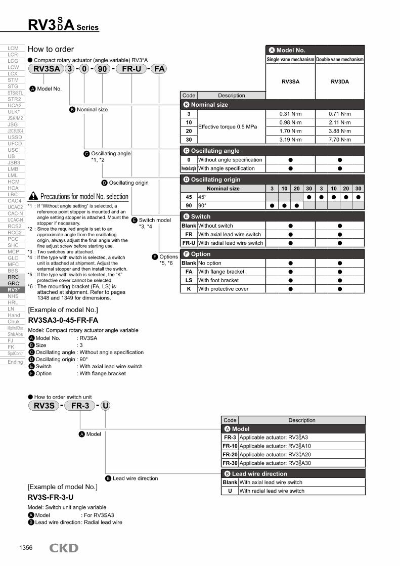
How to order Compact rotary actuator (angle variable) RV3*A
[Example of model No.]RV3SA3-0-45-FR-FAModel: Compact rotary actuator angle variableA Model No. : RV3SAB Size : 3C Oscillating angle : Without angle specificationD Oscillating origin : 90°E Switch : With axial lead wire switchF Option : With flange bracket
[Example of model No.]RV3S-FR-3-UModel: Switch unit angle variableA Model : For RV3SA3B Lead wire direction : Radial lead wire
UFR-3RV3S How to order switch unit
FR-U03RV3SA FA90
*1 : If “Without angle setting” is selected, a reference point stopper is mounted and an angle setting stopper is attached. Mount the stopper if necessary.
*2 : Since the required angle is set to an approximate angle from the oscillating origin, always adjust the final angle with the fine adjust screw before starting use.
*3 : Two switches are attached.*4 : If the type with switch is selected, a switch
unit is attached at shipment. Adjust the external stopper and then install the switch.
*5 : If the type with switch is selected, the “K” protective cover cannot be selected.
*6 : The mounting bracket (FA, LS) is attached at shipment. Refer to pages 1348 and 1349 for dimensions.
Precautions for model No. selection
Model No.A
Oscillating angle *1, *2
C
Switch model*3, *4
E
Options*5, *6
F
Nominal sizeB
Oscillating originD
ModelA
Lead wire directionB
A Model No.Single vane mechanism Double vane mechanism
RV3SA RV3DA
Code DescriptionB Nominal size3
Effective torque 0.5 MPa
0.31 N·m 0.71 N·m10 0.98 N·m 2.11 N·m20 1.70 N·m 3.88 N·m30 3.19 N·m 7.70 N·m
C Oscillating angle0 Without angle specification
Needed angle With angle specification
D Oscillating originNominal size 3 10 20 30 3 10 20 30
45 45°90 90°
E SwitchBlank Without switch
FR With axial lead wire switchFR-U With radial lead wire switch
F OptionBlank No option
FA With flange bracketLS With foot bracketK With protective cover
Code DescriptionA Model
FR-3 Applicable actuator: RV3 A3FR-10 Applicable actuator: RV3 A10FR-20 Applicable actuator: RV3 A20FR-30 Applicable actuator: RV3 A30
B Lead wire directionBlank With axial lead wire switch
U With radial lead wire switch
SD
SDSDSD
RV3 A SeriesSD
LCMLCRLCGLCWLCXSTMSTGSTS/STLSTR2UCA2ULK*JSK/M2JSGJSC3/JSC4USSDUFCDUSCUBJSB3LMBLMLHCMHCALBCCAC4UCAC2CAC-NUCAC-NRCS2RCC2PCCSHCMCPGLCMFCBBSRRCGRCRV3*NHSHRLLNHandChukMecHnd/ChukShkAbsFJFKSpdContr
Ending
1356

RV3 A SeriesOscillating origin position/oscillating time setting
Oscillating time setting1. Use an oscillating time within the specified range of the table below. If this
range is exceeded, smooth operation cannot be obtained due to stick slip, etc.
*1 : Tolerance of oscillating origin is based on set screw position.
Oscillating origin position
RV3DA3 to 30 Oscillating origin 45° RV3SA30
Oscillating origin 90° RV3SA3 to 20
SD
Osc
illat
ing
time
(s)
Osc
illat
ing
time
(s)
Osc
illat
ing
time
(s)
Osc
illat
ing
time
(s)
Oscillating angle (degree)
Oscillating angle (degree)
Oscillating angle (degree)
Oscillating angle (degree)
Angle setting range
Oscillating angle range
30°
Oscillating origin 45°
Port position
Angle setting rangeOscillating angle range
Oscillating origin 90°
30°
Angle setting rangeOscillating angle range
Port position30°
Oscillating origin 45°
Port position
RV3SDA30 RV3S
DA20
RV3SDA10 RV3S
DA3
LCMLCRLCGLCWLCXSTMSTGSTS/STLSTR2UCA2ULK*JSK/M2JSGJSC3/JSC4USSDUFCDUSCUBJSB3LMBLMLHCMHCALBCCAC4UCAC2CAC-NUCAC-NRCS2RCC2PCCSHCMCPGLCMFCBBSRRCGRCRV3*NHSHRLLNHandChukMecHnd/ChukShkAbsFJFKSpdContr
Ending
1357

RV3 A20, 30 RV3 A3 to 10
Unit: N·mOutput table (effective torque)Working pressure (MPa)
0.2 0.3 0.4 0.5 0.6 0.7 0.8 0.9 1.0Model No.
Single vane
RV3SA3 0.1 0.17 -0.24 -0.31 0.38 0.45 - - -
RV3SA10 0.35 0.56 0.75 0.98 1.2 1.39 - - -
RV3SA20 0.59 0.95 1.33 1.7 2.1 2.49 2.87 3.26 3.68
RV3SA30 1.1 1.8 2.5 3.19 4.1 4.8 5.8 6.5 7.2
Double vane
RV3DA3 0.25 0.39 0.54 0.71 0.86 1.01 - - -
RV3DA10 0.76 1.17 1.62 2.11 2.54 3.03 - - -
RV3DA20 1.4 2.22 3.06 3.88 4.7 5.53 6.33 7.17 8.07
RV3DA30 2.7 4.4 6 7.7 9.5 11.2 12.99 14.8 16.6
Output table (effective torque)SD
SD
RV3 A SeriesSD
RV3SA10
RV3SA3
RV3DA3
RV3DA10
Working pressure (MPa)
4
3.5
3
2.5
2
1.5
1
0.5
10.500
RV3SS20
RV3DA20RV3SA30
RV3DA30
Working pressure (MPa)
10.50
18
16
14
12
10
8
6
4
2
0
Out
put (
N·m
)
Out
put (
N·m
)
LCMLCRLCGLCWLCXSTMSTGSTS/STLSTR2UCA2ULK*JSK/M2JSGJSC3/JSC4USSDUFCDUSCUBJSB3LMBLMLHCMHCALBCCAC4UCAC2CAC-NUCAC-NRCS2RCC2PCCSHCMCPGLCMFCBBSRRCGRCRV3*NHSHRLLNHandChukMecHnd/ChukShkAbsFJFKSpdContr
Ending
1358

Internal structure and parts list RV3SA*
RV3SDA*
* The internal structure of the rotary actuator body is the same as the compact rotary actuator RV3 . Refer to page 1342 for details.
No. Part name Material Remarks No. Part name Material Remarks1 Stopper L Steel Reference point 5 Finger mounting bolt Steel2 Lock nut Steel 6 Stopper R Steel Angle setting3 Fine adjusting screw Steel 7 Stopper mounting bolt Steel4 Finger Steel
RV3 A SeriesInternal structure and parts list
SD
SD
Single vane
7654321
53214
67
Double vane
LCMLCRLCGLCWLCXSTMSTGSTS/STLSTR2UCA2ULK*JSK/M2JSGJSC3/JSC4USSDUFCDUSCUBJSB3LMBLMLHCMHCALBCCAC4UCAC2CAC-NUCAC-NRCS2RCC2PCCSHCMCPGLCMFCBBSRRCGRCRV3*NHSHRLLNHandChukMecHnd/ChukShkAbsFJFKSpdContr
Ending
1359

Dimensions RV3SA3
RV3DA3
Radial lead wire Axial lead wire
RV3 A3-*-K (with protective cover)
RV3 A3-*-FR(U)
RV3 A SeriesSD
SD
SD
Fine adjusting screwFingerR15.5Stopper for angle setting
Stopper for reference point
Stopper mounting pitch 15°
Max. setting angle 180°
M2
Fine adjusting screw
Min. setting angle 30°4.560°60
°
30
25°25° 90°
3-M3 depth 6
Oscillating angle range: 30° to 180°
Oscillating origin
ø5h7
Port 2-M5
ø36.
5ø1
2 h8
16.5
10419
55
10
26
Port position
Stopper for reference point
Stopper for angle setting
R15.
5
FingerStopper mounting pitch 15°
M2
Fine adjusting screw
Fine adjusting screw
Min. setting angle 30°
Max. setting angle 90°
4.5
60° 60° Oscillating angle range 30° to 90°
30
Port position Oscillating origin45°
25° 25°
3-M3 depth 6
ø5h7
Port 2-M5
ø36.
5ø1
2 h8
16.5
10419
55
10
26
CT-3R CT-3L
505
17.2 2239.2 100045
CT-3RU CT-3LU
550
1000
17.2 2239.245
ø19
65.720.7
ø35
LCMLCRLCGLCWLCXSTMSTGSTS/STLSTR2UCA2ULK*JSK/M2JSGJSC3/JSC4USSDUFCDUSCUBJSB3LMBLMLHCMHCALBCCAC4UCAC2CAC-NUCAC-NRCS2RCC2PCCSHCMCPGLCMFCBBSRRCGRCRV3*NHSHRLLNHandChukMecHnd/ChukShkAbsFJFKSpdContr
Ending
1360

Dimensions RV3SA10
RV3DA10
Radial lead wire Axial lead wire
RV3 A10-*-K (with protective cover)
RV3 A10-*-FR(U)
RV3 A SeriesCompact/angle variable
SD
SD
SD
Stopper for angle setting
Stopper for reference point
Finger
Stopper mounting pitch 15°
M2
Min. setting angle 30°
Fine adjusting screw
Max. setting angle 180°
Fine adjusting screw
R18
5.5
120° 120°
90°25°25°
35
3-M3 depth 6Oscillating angle range: 30° to 180°
Oscillating origin
Port position
ø6h7
ø14 h
8
14
25Port 2-M5
ø42.
523 405
1275
R18
Stopper for angle setting
Stopper for reference point
FingerStopper mounting pitch 15°
M2
Min. setting angle 30°
Fine adjusting screw
Max. setting angle 90°
Fine adjusting screw
5.5
45°Oscillating origin
25°
120°
25°
120°
35
Port position
3-M3 depth 6
Oscillating angle range 30° to 90°
75
12
ø6h7
54023
ø42.
5
Port2-M525
14
ø14 h
8
550
1000CT-3R CT-3L18.2 22
40.263
CT-3RU
550
1000
18.2 2240.263
CT-3LU
84.721.7
ø41
ø19
LCMLCRLCGLCWLCXSTMSTGSTS/STLSTR2UCA2ULK*JSK/M2JSGJSC3/JSC4USSDUFCDUSCUBJSB3LMBLMLHCMHCALBCCAC4UCAC2CAC-NUCAC-NRCS2RCC2PCCSHCMCPGLCMFCBBSRRCGRCRV3*NHSHRLLNHandChukMecHnd/ChukShkAbsFJFKSpdContr
Ending
1361

Dimensions RV3SA20
* The key is attached. Refer to page 1349 for the key dimensions.
* The key is attached. Refer to page 1349 for the key dimensions.
RV3DA20
Radial lead wire Axial lead wire
RV3 A20-*-K (with protective cover)
RV3 A20-*-FR(U)
RV3 A SeriesSD
SD
SD
Keyway width 3 × depth 1.8-0.004
-0.029+0.1
0
Stopper for angle setting (Stopper R)
Max. setting angle 180°
R20 Finger
Min. setting angle 30°
Stopper for reference point (Stopper L)
Fine adjusting screw Fine adjusting screw
Stopper mounting pitch 15°
M245° 45°
25°25° 90°
40
Port position
4-M5 depth 8
Oscillating angle range: 30° to 180°
Oscillating origin
16
55
ø8h7
36.5
3
Port 2-M5
ø49.
528.55.5
ø16 h
896
12.5
Finger
Fine adjusting screw
Min. setting angle 30°
Stopper mounting pitch 15°
Stopper for reference point (Stopper L)
Max. setting angle 90°
Fine adjusting screw
Stopper for angle setting (Stopper R)
R20
M2
25°25°45°
Port position
4-M5 depth 8
Oscillating origin
16
55
36.5
3
Port 2-M5
28.55.5
12.596
Oscillating angle range 30° to 90°
19.2 2241.2
550
1000
CT-3LCT-3R
83.5
CT-3RU CT-3LU
5
50
100019.2 22
41.283.5
106.2
ø49
22.7
ø19
45° 45°
40
Keywaywidth 3 × depth 1.8-0.004
-0.029+0.1
0
ø8h7
ø49.
5ø1
6 h8
LCMLCRLCGLCWLCXSTMSTGSTS/STLSTR2UCA2ULK*JSK/M2JSGJSC3/JSC4USSDUFCDUSCUBJSB3LMBLMLHCMHCALBCCAC4UCAC2CAC-NUCAC-NRCS2RCC2PCCSHCMCPGLCMFCBBSRRCGRCRV3*NHSHRLLNHandChukMecHnd/ChukShkAbsFJFKSpdContr
Ending
1362

Dimensions RV3SA30
* The key is attached. Refer to page 1349 for the key dimensions.
RV3DA30
Radial lead wire Axial lead wire
RV3 A30-*-K (with protective cover)
RV3 A30-*-FR(U)
RV3 A SeriesCompact/angle variable
SD
* The key is attached. Refer to page 1349 for the key dimensions.
SD
SD
Port position
Port 2-Rc1/8
5.531.5
3 18
60
36
14105.5
R26.5
M2
Max. setting angle 270°
Stopper mounting pitch 15°
Min. setting angle 30°
Stopper for reference point (Stopper L)
Fine adjusting screw
Stopper for angle setting (Stopper R)
Fine adjusting screw
Finger
25°45°
Oscillating angle range 30° to 90°
Oscillating origin
25°
4-M5 depth 8 5.531.5
3 18
60
36
14105.5
Max. setting angle 90°
Stopper mounting pitch 15°
Min. setting angle 30°
Stopper for angle setting
M2 Fine adjusting screw
Stopper for reference point(Stopper L)
Fine adjusting screw
FingerR26
.5
CT-3LUCT-3RU
5501000
21.2 2243.291.5
ø19
ø63
117.125.6
91.521.2 22 CT-3LCT-3R
550
100043.2
ø63
Keywaywidth 4 ×depth 2.50
-0.030+0.10
25°25°45°
45°
56
45°
Port position
4-M5 depth 8Oscillating angle range 30° to 270°
Oscillating origin
ø10 h
7
ø64
ø20 h
8
45°
56
45°
ø10 h
7
ø64
ø20 h
8
Keyway width 4 × depth 2.50
-0.030+0.1
0
Port 2-Rc1/8
(Stopper R)
LCMLCRLCGLCWLCXSTMSTGSTS/STLSTR2UCA2ULK*JSK/M2JSGJSC3/JSC4USSDUFCDUSCUBJSB3LMBLMLHCMHCALBCCAC4UCAC2CAC-NUCAC-NRCS2RCC2PCCSHCMCPGLCMFCBBSRRCGRCRV3*NHSHRLLNHandChukMecHnd/ChukShkAbsFJFKSpdContr
Ending
1363

JIS symbol
SD
Large rotary actuator Vane mechanism/standard
RV3 Series Torque size: 50/150/300/800 Oscillating angle: 90°/100°/180°/270°/280°
*1 : The min. working pressure is 0.3 MPa when the optional shock absorber is selected.
*2 : Calculate the allowable energy with allowable inertia energy of the shaft of the rotary actuator as follows. [Allowable energy] ≥ (1/2) x I x ω2 x 10³ (refer to page 1398 for details).If the formula above is not satisfied, problems such as broken shafts may be caused.
*3 : The max. operating frequency is at a supply pressure of 0.5 MPa [without load].
*4 : A key is attached with the rotary actuator with keyway.
*5 : Contact CKD for products other than standard specifications.
*6 : The switch unit weight is the weight of two switches.
Specifications Single vane mechanism
Item Single vane mechanism RV3SSize 50 150 300 800Effective torque N·m 4.7 14.7 27.9 102Actuation Single vaneWorking fluid Compressed airMax. working pressure MPa 1.0 (≈150 psi, 10 bar)Min. working pressure MPa 0.2 (≈29 psi, 2 bar)Proof pressure MPa 1.5 (≈220 psi, 15 bar)Ambient temperature °C 5 (41°F) to 60 (140°F)Port size Rc1/8 Rc1/4 Rc3/8 Rc1/2Oscillating angle tolerance Degree 90 180 270 280 90 180 270 280 90 180 270 280 90 180 270 280 Oscillating origin Degree 45 40 45 40 45 40 45 40Allowable absorbed energy *2 mJ 49 225 1078 3820Max. operating freq *3 cycle/min 180 90 60 120 80 50 90 60 40 70 45 30Volumetric capacity cm3 51 61 62 146 179 185 244 283 352 365 754 869 1036 1046Allowable radial load N 588 1176 1960 4900Allowable thrust load N 44.1 88.2 147 490Weight kg 0.82 0.79 0.73 0.7 2.0 1.9 1.7 1.6 3.7 3.6 12.7 12.2 11.2 11.0
Switc
h un
it weig
ht k
g *6 Without shock absorber 0.1 0.14 0.18 0.28
With shock absorber
90° 0.16 0.27 0.50 2.9100° 0.15 0.26 0.49 2.8180° 0.16 0.27 0.50 2.9270° 0.14 0.23 0.41 2.7280° 0.14 0.22 0.39 2.6
Lubrication Not required (use turbine oil class 1 ISO VG32 if necessary for lubrication)
+3+0
+3+0
+3+0
+3+0
+3+0
+3+0
+3+0
+3+0
+3+0
+3+0
+3+0
+3+0
+3+0
+3+0
+3+0
+3+0
*1
Double vane mechanism
Item Double vane mechanism RV3DSize 50 150 300 800Effective torque N·m 10.1 34.3 66.6 206Actuation Double vaneWorking fluid Compressed airMax. working pressure MPa 1.0 (≈150 psi, 10 bar)Min. working pressure MPa 0.2 (≈29 psi, 2 bar)Proof pressure MPa 1.5 (≈220 psi, 15 bar)Ambient temperature °C 5 (41°F) to 60 (140°F)Port size Rc1/8 Rc1/4 Rc3/8 Rc1/2Oscillating angle tolerance Degree 90 100 90 100 90 100 90 100 Oscillating origin Degree 45 40 45 40 45 40 45 40Allowable absorbed energy *2 mJ 49 225 1078 3820Max. operating frequency *3 cycle/min 180 120 90 90 70Volumetric capacity cm3 42 43 127 123 244 271 754 774Allowable radial load N 588 1176 1960 4900Allowable thrust load N 44.1 88.2 147 490Weight kg 0.82 0.8 2.0 1.9 4.3 4.1 12.7 12.5
Switc
h un
it weig
ht kg
*6 Without shock absorber 0.1 0.14 0.18 0.28
With shock absorber
90° 0.16 0.27 0.50 2.9100° 0.15 0.26 0.49 2.8180° 0.16 0.27 0.50 2.9270° 0.14 0.23 0.41 2.7280° 0.14 0.22 0.39 2.6
Lubrication Not required (use turbine oil ISO VG32 if necessary for lubrication)
+3+0
+3+0
+3+0
+3+0
+3+0
+3+0
+3+0
+3+0
*1
LCMLCRLCGLCWLCXSTMSTGSTS/STLSTR2UCA2ULK*JSK/M2JSGJSC3/JSC4USSDUFCDUSCUBJSB3LMBLMLHCMHCALBCCAC4UCAC2CAC-NUCAC-NRCS2RCC2PCCSHCMCPGLCMFCBBSRRCGRCRV3*NHSHRLLNHandChukMecHnd/ChukShkAbsFJFKSpdContr
Ending
1364

RV3 SD Series
Operational principle
Operational principle Double vane
1. Configured with two vanes sliding on the internal body surface, integrated shaft, and two shoes (stoppers).
2. Air from port A pushes vane, goes through passage in shaft, pushes another vane, turns shaft, and finally generates torque.
3. Rotates in the same way as the single vane.
Single vane1. Configured with vane sliding on the internal body surface,
integrated shaft, and shoe (stopper).2. Air from port A pushes vane, rotates shaft, and generates
torque.3. Air in opposite chamber is exhausted from port B, and the shaft
rotates clockwise.4. Vane stops when it contacts the shoe.5. Air supply from port B causes counterclockwise rotation in the
same manner.
Switch specifications
ItemProximity 2-wire Proximity 3-wire Reed 2-wire
M2V M3V MOV M5V
Applications Dedicated for programmable controller
For programmable controller, relay, IC circuit, compact solenoid valve
For programmable controller, relay
For programmable controller, relay, IC circuit (without indicator lamp), serial connection
Output method — NPN output —Power supply voltage — 4.5 to 28 VDC —
Load voltage/current 10 to 30 VDC, 5 to 30 mA
30 VDC or less, 100 mA or less
5 to 50 mA with 12/24 VDC, 7 to 20 mA with 110 VAC
50 mA or less with 5/12/24 VDC, 20 mA or less with 110 VAC
Indicator lamp LED (Lit when ON) LED (Lit when ON) Without indicator lampLeakage current 1 mA or less 10 μA or less 0 mAWeight g 1 m:22 3 m:57 5 m:93
Shoe
Vane
Body
Shaft
ABAB
Vane
ShoeB A
Body
Shaft
AB
LCMLCRLCGLCWLCXSTMSTGSTS/STLSTR2UCA2ULK*JSK/M2JSGJSC3/JSC4USSDUFCDUSCUBJSB3LMBLMLHCMHCALBCCAC4UCAC2CAC-NUCAC-NRCS2RCC2PCCSHCMCPGLCMFCBBSRRCGRCRV3*NHSHRLLNHandChukMecHnd/ChukShkAbsFJFKSpdContr
Ending
1365
RV3 SeriesSD
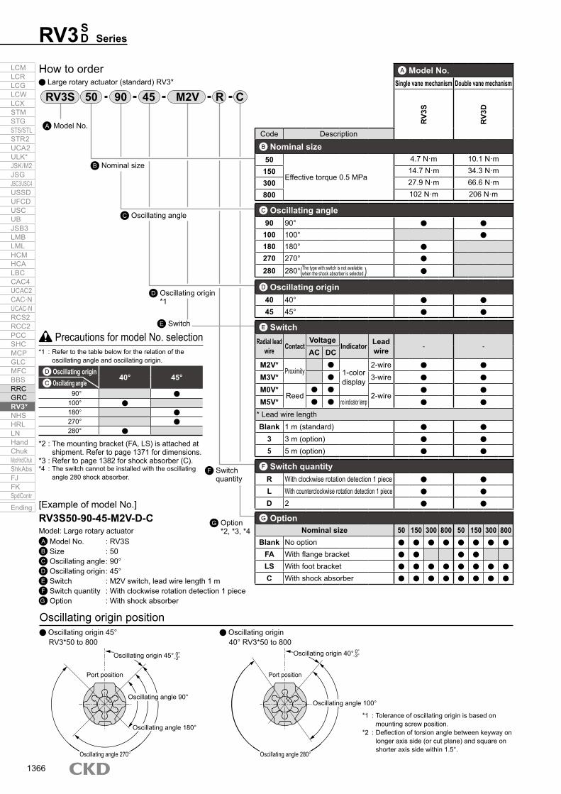
How to order Large rotary actuator (standard) RV3*
Oscillating origin position Oscillating origin 40° RV3*50 to 800
Oscillating origin 45° RV3*50 to 800
RV3S M2V CR4550 90
*1 : Tolerance of oscillating origin is based on mounting screw position.
*2 : Deflection of torsion angle between keyway on longer axis side (or cut plane) and square on shorter axis side within 1.5°.
Model No.A
Nominal sizeB
Oscillating angleC
SwitchE
Switch quantity
F
Oscillating origin*1
D
Option *2, *3, *4
G
A Model No.Single vane mechanism Double vane mechanism
RV3
S
RV3
D
Code DescriptionB Nominal size50
Effective torque 0.5 MPa
4.7 N·m 10.1 N·m150 14.7 N·m 34.3 N·m300 27.9 N·m 66.6 N·m800 102 N·m 206 N·m
C Oscillating angle90 90°
100 100°180 180°270 270°
280 280°( )D Oscillating origin40 40°45 45°
E SwitchRadial lead
wire ContactVoltage
Indicator Lead wire - -
AC DCM2V*
Proximity
1-color display
2-wireM3V* 3-wireM0V*
Reed
2-wireM5V* no indicator lamp
* Lead wire lengthBlank 1 m (standard)
3 3 m (option)5 5 m (option)
F Switch quantityR With clockwise rotation detection 1 pieceL With counterclockwise rotation detection 1 pieceD 2
G OptionNominal size 50 150 300 800 50 150 300 800
Blank No optionFA With flange bracketLS With foot bracketC With shock absorber
The type with switch is not available when the shock absorber is selected.
[Example of model No.]RV3S50-90-45-M2V-D-CModel: Large rotary actuatorA Model No. : RV3SB Size : 50C Oscillating angle : 90°D Oscillating origin : 45°E Switch : M2V switch, lead wire length 1 mF Switch quantity : With clockwise rotation detection 1 pieceG Option : With shock absorber
*1 : Refer to the table below for the relation of the oscillating angle and oscillating origin.
Relation of oscillating angle and oscillating origin
*2 : The mounting bracket (FA, LS) is attached at shipment. Refer to page 1371 for dimensions.
*3 : Refer to page 1382 for shock absorber (C).*4 : The switch cannot be installed with the oscillating
angle 280 shock absorber.
Precautions for model No. selection
D Oscillating origin40° 45°
C Oscillating angle90°
100°180°270°280°
0°-3°
0°-3°
Port position
Oscillating origin 40°
Oscillating angle 100°
Oscillating angle 280°
Port position
Oscillating origin 45°
Oscillating angle 90°
Oscillating angle 180°
Oscillating angle 270°
LCMLCRLCGLCWLCXSTMSTGSTS/STLSTR2UCA2ULK*JSK/M2JSGJSC3/JSC4USSDUFCDUSCUBJSB3LMBLMLHCMHCALBCCAC4UCAC2CAC-NUCAC-NRCS2RCC2PCCSHCMCPGLCMFCBBSRRCGRCRV3*NHSHRLLNHandChukMecHnd/ChukShkAbsFJFKSpdContr
Ending
1366

RV3 SD Series
How to order
Output characteristics graph (effective torque)
How to order switch unitSwitch unit
Precautions for model No. selection
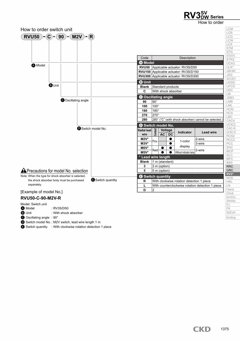
90 M2VC RRVU50
[Example of model No.]RVU50-C-90-M2V-RModel: Switch unitA Model : RV3S/D50B Unit : With shock absorberC Oscillating angle : 90°D Switch model No. : M2V switch, lead wire length 1 mE Switch quantity : With clockwise rotation
detection 1 piece
Oscillating time setting1. Use an oscillating time within the specified range of the table below. If this range
is exceeded, smooth operation cannot be obtained due to stick slip, etc.
Unit: N·m
(s)
Model No.Oscillating angle
90° 100° 180° 270° 280°RV3 50 0.08 to 0.8 0.09 to 0.9 0.16 to 1.6 0.24 to 2.4 0.25 to 2.5
RV3 150 0.12 to 1.2 0.13 to 1.3 0.24 to 2.4 0.36 to 3.6 0.37 to 3.7
RV3 300 0.16 to 1.6 0.17 to 1.7 0.32 to 3.2 0.48 to 4.8 0.49 to 4.9
RV3*800 0.22 to 2.2 0.24 to 2.4 0.44 to 4.4 0.66 to 6.6 0.68 to 6.8
SDSDSD
ModelA
Oscillating angleC
UnitB
Switch model No.D
Switch quantityE
Code DescriptionA ModelRVU50 Applicable actuator: RV3S/D50
RVU150 Applicable actuator: RV3S/D150RVU300 Applicable actuator: RV3S/D300RVU800 Applicable actuator: RV3S/D800
B UnitBlank Standard products
C With shock absorber
C Oscillating angle90 90°100 100°180 180°270 270°280 280° (“C” (for shock absorber) cannot be selected.)
D Switch model No.M2V*
Prox.1-color display
2-wireM3V* 3-wireM0V*
Reed 2-wireM5V* Without indicator lamp
* Lead wire lengthBlank 1 m (standard)
3 3 m (option)5 5 m (option)
E Switch quantityR With clockwise rotation detection 1 pieceL With counterclockwise rotation detection 1 pieceD 2
Note: When the type for shock absorber is selected, the shock absorber body must be purchased separately.
RV3 SD 50/150/300/800 Output table (effective torque)
Working pressure (MPa)0.2 0.3 0.4 0.5 0.6 0.7 0.8 0.9 1.0Model No.
Single vane
RV3S50 1.25 2.59 -3.69 -4.79 5.9 -7 8.29 9.5 10.6
RV3S150 5.5 8.5 11.5 15 18 21 24 27.3 30.5
RV3S300 10.5 16.5 22.5 28.5 34.5 40.5 46 51.8 57.5
RV3S800 37.8 59.1 81 102 123 144 166 186 205
Double vane
RV3D50 3.3 5.79 8.29 10.4 12.8 15.1 17.6 20.1 22.5
RV3D150 12.5 19 27 35 41.5 48 55 62 69
RV3D300 25.5 39 54 68 83 97 110 124 137
RV3D800 77.4 120 161 206 247 288 332 371 411
450
400
350
300
Out
put (
N·m
) 250
200
150
100
50
0 0.2
Working pressure (MPa)
0.4 0.6 0.8 1 1.20
RV3D80
0
RV3S800
RV3D300
RV3D150RV3S300RV3S150RV3D50RV3S50
LCMLCRLCGLCWLCXSTMSTGSTS/STLSTR2UCA2ULK*JSK/M2JSGJSC3/JSC4USSDUFCDUSCUBJSB3LMBLMLHCMHCALBCCAC4UCAC2CAC-NUCAC-NRCS2RCC2PCCSHCMCPGLCMFCBBSRRCGRCRV3*NHSHRLLNHandChukMecHnd/ChukShkAbsFJFKSpdContr
Ending
1367

RV3 SeriesSD
Internal structure and parts list RV3S50/150/300
No. Part name Material Remarks No. Part name Material Remarks1 Body A Aluminum casting 7 Damper Resin2 Body B Aluminum casting 8 O-ring Nitrile rubber3 Vane shaft Steel 9 Bearing Sintering oil impregnated material4 Vane seal (vane shaft) Nitrile rubber 10 O-ring Nitrile rubber5 Shoe Zinc alloy die-casting 11 Bearing Steel6 Shoe sealant Nitrile rubber 12 Cover plate Steel
RV3D50/150/300
RV3S800/RV3SH800
RV3D800/RV3DH800
Refer to page 1393 for the repair parts list.Note: The vane seal and vane shaft are integrated.
6 2104189375
6 210 1112 419375
6 21012 11419375
26104189375
LCMLCRLCGLCWLCXSTMSTGSTS/STLSTR2UCA2ULK*JSK/M2JSGJSC3/JSC4USSDUFCDUSCUBJSB3LMBLMLHCMHCALBCCAC4UCAC2CAC-NUCAC-NRCS2RCC2PCCSHCMCPGLCMFCBBSRRCGRCRV3*NHSHRLLNHandChukMecHnd/ChukShkAbsFJFKSpdContr
Ending
1368

RV3 SD Series
Large/standardDimensions
RV3 SD 50/150/300
* The key is attached. Refer to page 1371 for the key dimensions.
With switch, shock absorber
With switch
* The key is attached. Refer to page 1371 for the key dimensions.
Code A B C D E F G H J K L M N P Q R S T Key groove W x D x L U W V Z X X’ Y Y’Model No.
RV3 50 79 145 19.5 86 39.5 12 25 29 2.5 10 13 36 16 Rc1/8 45M6
5 28 4×2.5×20 57 44 68 58 20 5 11 3Depth 9
RV3 150 110 180 23.5 103 53.5 17 30 34.5 3 13 16 51 24 Rc1/4 70M8
5 34 5×3×36 85 61 97 85.2 23.5 6 10.5 5Depth 12
RV3 300 141.5 220 30 125 65 25 45 41.5 3.5 19 22 66 32 Rc3/8 80M10
5 42 7×4×40 98.5 78 125 110 27.5 8 13 4.5Depth 15
Code A B1 B2 C1 C2 D E F G H J M N P Q R S T V W1 W2 KeywayW x D x LModel No.
RV3 50 79 157.2 177.2 30.5 50.5 87.2 39.5 12 25 29 2.5 36 16 Rc1/8 45M6
5 28 54 47 58 4×2.5×20Depth 9
RV3 150 110 188.2 214.2 30.5 56.5 104.2 53.5 17 30 34.5 3 51 24 Rc1/4 70M8
5 34 71.5 61 72 5×3×36Depth 12
RV3 300 141.5 221.7 253.7 30.5 62.5 126.2 65 25 45 41.5 3.5 66 32 Rc3/8 80M10
5 42 95 69 88 7×4×40Depth 15
SD
SD
SD
SD
SD
SD
Oscillating origin 45°Oscillating origin 40°
NøFh7
øGh8
H
øZ
Y’Y
X’
T
S L
CJJ
EB
D
Keyway
X X2-P
K
Oscillating origin
Oscillating angle 280°
Oscillating angle 100°
40°
(Rear side 6)
øQ
øAW
øV
øU
Oscillating origin
45°
M
12-R
Oscillating angle 270°+3
0 +30
+30
+30
Oscillating angle 180°Oscillating angle 90°
+0.1-0.1
N
J
øGh8
øGh8
R W1
C1
Keyway
S
øFh7
øFh7
øA
2-PH T
MEB1D
6-R
øQ M
N
J
R W2C2
Keyway
S
øA
2-P
H T
VE
B2D
6-R
øQ M
LCMLCRLCGLCWLCXSTMSTGSTS/STLSTR2UCA2ULK*JSK/M2JSGJSC3/JSC4USSDUFCDUSCUBJSB3LMBLMLHCMHCALBCCAC4UCAC2CAC-NUCAC-NRCS2RCC2PCCSHCMCPGLCMFCBBSRRCGRCRV3*NHSHRLLNHandChukMecHnd/ChukShkAbsFJFKSpdContr
Ending
1369

RV3 SeriesSD
Dimensions RV3 S
D 800
With switch
With switch, shock absorber
Oscillating angle 280°+30
Oscillating origin 40°
Oscillating angle 100°+30
Oscillating origin 45°
Oscillating origin
+30
+30
0-0.1
0-0.043
+0.20
+30
Oscillating angle 180°Oscillating angle 270°
32
Oscillating angle 90°
40°
(Rear side 6)
ø196
ø196
ø196
ø152
44
4444
ø173
ø120
110
Oscillating origin
45°
90
90
135
32.532.5
53.5 64
14.569.5
69.5
69.5
42.5
73
171
174
171
285
286
313.5
44.54.5
4.5
4.5
4.5
11
10
7
35
2-Rc1/2
12-M12 depth 18
Keyway (width × depth × length)
Keyway (width × depth × length)
2-Rc1/2
2-Rc1/2
53.5
53.5
64
64
R55.5
R115
ø40 h
7
ø70 h
8
Keyway (width × depth × length)12 × 5 × 40
0-0.043
+0.2012 × 5 × 40
0-0.043
+0.2012 × 5 × 40
ø40 h
7ø4
0 h7
ø70 h
8ø7
0 h8
LCMLCRLCGLCWLCXSTMSTGSTS/STLSTR2UCA2ULK*JSK/M2JSGJSC3/JSC4USSDUFCDUSCUBJSB3LMBLMLHCMHCALBCCAC4UCAC2CAC-NUCAC-NRCS2RCC2PCCSHCMCPGLCMFCBBSRRCGRCRV3*NHSHRLLNHandChukMecHnd/ChukShkAbsFJFKSpdContr
Ending
1370

RV3 SD Series
Options/accessories
Model CompatibilityRVS50 RV3 50RVS150 RV3 150RVS300 RV3 300RVS800 RV3 800
Options/accessories
FA LSFlange bracket
Model Model
How to order
Foot bracket
Foot bracket Flange bracket
Flange bracket/foot bracket
Dimensions
Model CompatibilityRVS50 RV3 50RVS150 RV3 150
SD
SD
SD
SDSDSD
Model A B C D E F G H IRV*50 64 80 7 39.5 35 4.5 45 30 M6×12
RV*150 88 110 9 53.5 47.5 6 70 37 M8×12
Model A B C D E F G H J K L N ORV*50 55 75 11 45 82.5 35 27.5 4.5 10 25 45 30 M6×12
RV*150 80 110 13 65 115 43.5 33.5 10 12 28 70 37 M8×22RV*300 100 140 15 80 135 53 40.5 12 13 32 80 52 M10×28RV*800 140 200 15 110 200 54.5 39.5 15 15 35 120 75 M12×35
Model No. Nominal key b h C RRV3*50 4×4×20 4 -0
-0.03 4 -0-0.03 20 -0
-0.210.16 to 0.25
(R0.16 to 0.25)2
RV3*150 5×5×36 5 -0-0.03 5 -0
-0.03 36 -0-0.25
0.25 to 0.40(R0.25 to 0.40)
2.5
RV3*300 7×7×40 7 -0-0.036 7 -0
-0.036 40 -0-0.25
0.25 to 0.40(R0.25 to 0.40)
3.5
RV3*800 12×8×40 12 -0-0.043 8 -0
-0.09 40 -0-0.25 0.40 to 0.60 6
Unit: mm
JIS B1301 parallel key b x h x double round S45C
*1 : One bracket and mounting bolt (required quantity) are shipped.*2 : Flange bracket is not available for RV*300.
Note) Foot bracket can be installed rotating in 60° increments.
KeyDimensionsThe following keys are attached with the rotary actuator with keyway.
RVS 50150 -FA *2 RVS -LS
50150300800
Material: Steel Zinc chromate treatment
Material: Steel (50, 150) Cast iron (300, 800)Zinc chromate treatment
Weight 50:0.18 kg150:0.49 kg Weight 50:0.25 kg
150:1.05 kg 300:1.73 kg 800:3.9 kg
DE
4-C
BA
BA
H
(Size I)3-cross-recessed flat head machine screw
G
F
Approx. G
HF
KJ
ED
2-øCBA
N
L
6-hexagon socket head cap screw(Size 0)
25S
25S
h
2-R4-C
b
6.5S
6.5S
LCMLCRLCGLCWLCXSTMSTGSTS/STLSTR2UCA2ULK*JSK/M2JSGJSC3/JSC4USSDUFCDUSCUBJSB3LMBLMLHCMHCALBCCAC4UCAC2CAC-NUCAC-NRCS2RCC2PCCSHCMCPGLCMFCBBSRRCGRCRV3*NHSHRLLNHandChukMecHnd/ChukShkAbsFJFKSpdContr
Ending
1371

SVDW
*1 : The min. working pressure is 0.3 MPa when the optional shock absorber is selected.*2 : Calculate the allowable energy with allowable inertia energy of the shaft of the rotary actuator as follows.
[Allowable energy] ≥ (1/2) x I x ω2 x 10³ (refer to page 1398 for details). If the formula at left is not satisfied, problems such as broken shafts may be caused.
*3 : The max. operating frequency is at a supply pressure of 0.5 MPa [without load].*4 : A key is attached with the rotary actuator with keyway.*5 : Contact CKD for products other than standard specifications.*6 : The switch unit weight is the weight of two switches.
SpecificationsItem Single vane mechanism RV3SV/RV3SW Double vane mechanism RV3DV/RV3DW
Size 50 150 300 50 150 300Effective torque N·m 4.7 14.7 27.9 10.1 34.3 66.6Actuation Single vane Double vaneWorking fluid Compressed airMax. working pressure MPa 0.7 (≈100 psi, 7 bar)Min. working pressure MPa 0.2 (≈29 psi, 2 bar)Proof pressure MPa 1.05 (≈150 psi, 10.5 bar)Ambient temperature °C 5 (41°F) to 50 (122°F)Port size (suction) Rc1/8 Rc1/4 Rc3/8 Rc1/8 Rc1/4 Rc3/8Port size (exhaust) M5 Rc1/4 M5 Rc1/4Oscillating angle tolerance ° 90 180 270 280 90 180 270 280 90 180 270 280 90 100 90 100 90 100 Oscillating origin ° 45 40 45 40 45 40 45 40 45 40 45 40Allowable absorbed energy *2 mJ 49 225 1078 49 225 1078Max. operating frequency *3 cycle/min 180 90 60 120 80 50 90 60 40 180 120 90Volumetric capacity cm3 51 61 62 146 179 185 244 283 352 365 42 43 127 123 244 271Allowable radial load N 588 1176 1960 588 1176 1960Allowable thrust load N 44.1 88.2 147 44.1 88.2 147Incorporated solenoid valve 4KB119/4KB129 4KB219/4KB229 4KB119/4KB129 4KB219/4KB229Weight kg 0.9 0.84 0.81 2.2 2.0 1.9 4.1 4.0 0.93 0.91 2.3 2.2 4.7 4.5
Switc
h un
it we
ight
kg
*6 Without shock absorber 0.1 0.14 0.18 0.1 0.14 0.18
With shock absorber
90° 0.16 0.27 0.58 0.16 0.27 0.50100° 0.15 0.26 0.49 0.15 0.26 0.49180° 0.16 0.27 0.50 0.16 0.27 0.50270° 0.14 0.23 0.41 0.14 0.23 0.41280° 0.14 0.22 0.39 0.14 0.22 0.39
Lubrication Not required (use turbine oil class 1 ISO VG32 if necessary for lubrication) Not required (use turbine oil ISO VG32 if necessary for lubrication)
+3+0
+3+0
+3+0
+3+0
+3+0
+3+0
+3+0
+3+0
+3+0
+3+0
+3+0
+3+0
+3+0
+3+0
+3+0
+3+0
+3+0
+3+0
*1
Large rotary actuator vane mechanism/with valve
RV3 Series Torque size: 50, 150, 300 Oscillating angle: 90°, 100°, 180°, 270°, 280°
LCMLCRLCGLCWLCXSTMSTGSTS/STLSTR2UCA2ULK*JSK/M2JSGJSC3/JSC4USSDUFCDUSCUBJSB3LMBLMLHCMHCALBCCAC4UCAC2CAC-NUCAC-NRCS2RCC2PCCSHCMCPGLCMFCBBSRRCGRCRV3*NHSHRLLNHandChukMecHnd/ChukShkAbsFJFKSpdContr
Ending
1372

RV3SV DW Series
Specifications, operational principle
The double solenoid valve maintains the self-hold state when both the A solenoid and B solenoid are OFF.
(2) Double solenoid
(1) Single solenoid
Operational principle
* M0 switch can be used for 24 VAC and 48 VAC within load current range of 7 to 20 mA.
Switch specifications
*1 : 100 VAC and 200 VAC are available with 110 VAC and 220 VAC (60 Hz).*2 : Refer to page 1351 for the specifications of the 4KB1 Series.*3 : Refer to “Pneumatic Valves (CB-023SA)” for details on valves.
Valve specificationsItem Specifications (4KB2 Series) *2
Rated voltage *1 V 100 VAC(50/60 Hz) 200 VAC(50/60 Hz) 24 VDCStarting current A 0.056/0.044 0.028/0.022
0.075Holding current A 0.028/0.022 0.014/0.011Power consumption W 1.8/1.4 1.8Voltage fluctuation range ±10%Thermal class Class B molded coil
Item Proximity 2-wire Proximity 3-wireM2V M3V
Applications Dedicated for programmable controller Programmable controller, relay, IC circuit, small solenoid valveOutput method ——— NPN outputPower supply voltage ——— 4.5 to 28 VDC
Load voltage/current 10 to 30 VDC,5 to 30 mA
30 VDC or less, 100 mA or less
Indicator lamp LED (Lit when ON)Leakage current 1 mA or less 10 μA or lessWeight g 1 m:22 3 m:57 5 m:93
Item Reed 2-wireM0V M5V
Applications For programmable controller, relay Programmable controller, relay, IC circuit (without indicator lamp), serial connection
Load voltage/current 5 to 50 mA with 12/24 VDC,7 to 20 mA with 110 VAC
50 mA or less with 5/12/24 VDC, 20 mA or less with 110 VAC
Indicator lamp LED (Lit when ON) Without indicator lampLeakage current 0 mAWeight g 1 m:22 3 m:57 5 m:93
Vane returns to the oscillating origin when the solenoid valve turns OFF.
Solenoid valve B solenoid
Solenoid valve A solenoid
When the solenoid valve B solenoid is ON, the vane moves in the oscillating direction.
When the solenoid valve A solenoid is ON, the vane returns to the oscillating origin position.
Solenoid valve ONSolenoid valve OFF
Vane
A B
Vane
A B
LCMLCRLCGLCWLCXSTMSTGSTS/STLSTR2UCA2ULK*JSK/M2JSGJSC3/JSC4USSDUFCDUSCUBJSB3LMBLMLHCMHCALBCCAC4UCAC2CAC-NUCAC-NRCS2RCC2PCCSHCMCPGLCMFCBBSRRCGRCRV3*NHSHRLLNHandChukMecHnd/ChukShkAbsFJFKSpdContr
Ending
1373

RV3 SeriesSV DW
How to order Large rotary actuator (with valve) RV3*
RV3S M2V1V CR45150 90
Model No.A
ValveB
Nominal sizeC
Oscillating angleD
Valve voltageF
SwitchG
Switch quantity
H
Option *2, * 3, *4
I
Oscillating origin*1
E
VW
A Model No.Single vane mechanism Double vane mechanism
RV3
S
RV3
D
Code DescriptionB Valve
V Single solenoidW Double solenoid
C Nominal size50
Effective torque 0.5 MPa4.7 N·m 10.1 N·m
150 14.7 N·m 34.3 N·m300 27.9 N·m 66.6 N·m
D Oscillating angle90 90°
100 100°180 180°270 270°
280 280°( )E Oscillating origin40 40°45 45°
F Valve voltage1 100 VAC2 200 VAC3 24 VDC
G SwitchRadial lead
wire ContactVoltage
Indicator Lead wire - -
AC DCM2V*
Proximity
1-color display
2-wireM3V* 3-wireM0V*
Reed
2-wireM5V* no indicator lamp
* Lead wire lengthBlank 1 m (standard)
3 3 m (option)5 5 m (option)
H Switch quantityR With clockwise rotation detection 1 pieceL With counterclockwise rotation detection 1 pieceD 2
I OptionNominal size 50 150 300 50 150 300
Blank No optionFA With flange bracketLS With foot bracketC With shock absorber
The type with switch is not available when the shock absorber is selected.
[Example of model No.]RV3SV150-90-45-M2V-R-CModel: Large rotary actuator with valveA Model No. : RV3SB Valve : Single solenoidC Size : 150D Oscillating angle : 90°E Oscillating origin : 45°F Valve voltage : 100 VACG Switch : M2V switch, lead wire length 1 mH Switch quantity : With clockwise rotation detection 1 pieceI Option : With shock absorber
*1 : Refer to the table below for the relation of the oscillating angle and oscillating origin.
Relation of oscillating angle and oscillating origin
*2 : The mounting bracket (FA, LS) is attached at shipment. Refer to page 1371 for dimensions.
*3 : Refer to page 1382 for shock absorber (C).*4 : The switch cannot be installed with the oscillating
angle 280 shock absorber.
Precautions for model No. selection
E Oscillating origin40° 45°
D Oscillating angle90°
100°180°270°280°
LCMLCRLCGLCWLCXSTMSTGSTS/STLSTR2UCA2ULK*JSK/M2JSGJSC3/JSC4USSDUFCDUSCUBJSB3LMBLMLHCMHCALBCCAC4UCAC2CAC-NUCAC-NRCS2RCC2PCCSHCMCPGLCMFCBBSRRCGRCRV3*NHSHRLLNHandChukMecHnd/ChukShkAbsFJFKSpdContr
Ending
1374
RV3SV DW Series
How to order
90 M2VC RRVU50
Switch model No.D
Switch quantityE
Oscillating angleC
Unit
Model
How to order switch unit
B
A
Code DescriptionA ModelRVU50 Applicable actuator: RV3S/D50RVU150 Applicable actuator: RV3S/D150RVU300 Applicable actuator: RV3S/D300
B UnitBlank Standard products
C With shock absorber
C Oscillating angle90 90°100 100°180 180°270 270°280 280° (“C” (with shock absorber) cannot be selected.)
D Switch model No.Radial lead
wire Conta
ct Voltage Indicator Lead wireAC DCM2V*
Prox.
1-color display
2-wireM3V* 3-wireM0V*
Reed
2-wireM5V* Without indicator lamp* Lead wire lengthBlank 1 m (standard)
3 3 m (option)5 5 m (option)
E Switch quantityR With clockwise rotation detection 1 pieceL With counterclockwise rotation detection 1 pieceD 2
Precautions for model No. selection
[Example of model No.]RVU50-C-90-M2V-RModel: Switch unitA Model : RV3S/D50B Unit : With shock absorberC Oscillating angle : 90°D Switch model No. : M2V switch, lead wire length 1 mE Switch quantity : With clockwise rotation detection 1 piece
Note: When the type for shock absorber is selected, the shock absorber body must be purchased separately.
LCMLCRLCGLCWLCXSTMSTGSTS/STLSTR2UCA2ULK*JSK/M2JSGJSC3/JSC4USSDUFCDUSCUBJSB3LMBLMLHCMHCALBCCAC4UCAC2CAC-NUCAC-NRCS2RCC2PCCSHCMCPGLCMFCBBSRRCGRCRV3*NHSHRLLNHandChukMecHnd/ChukShkAbsFJFKSpdContr
Ending
1375

Dimensions RV3 50
R2
Single solenoid Double solenoid ON → A direction B solenoid ON → A directionOFF → B direction A solenoid ON → B direction
* The key is attached. Refer to page 1371 for the key dimensions.
* The key is attached. Refer to page 1371 for the key dimensions.
Single solenoid Double solenoid ON → A direction B solenoid ON → A directionOFF → B direction A solenoid ON → B direction
SVDW
RV3 150/300SVDW
Code A B C D E F G H J K L M N Rc Rc’ Q R S T V W Key groove W x D x LModel No.
RV3*V150 110 180 23.5 103 53.5 17 30 36 3 13 16 79 62 1/4 1/4 70 M8 depth 12 5 41 65 70 5×3×36RV3*V300 141.5 220 30 125 65 25 45 47.5 3.5 19 22 95 72 3/8 1/4 80 M10 depth 15 5 50.5 80 70 7×4×40
RV3 SeriesSV DW
44
PSolenoidA
55
R1R2
SolenoidBRc1/8
12-M6 × 1 depth 9(Rear side 6) ø79
60 ø45
A
B
(Exhaust port)R1 R2-position
3429
(Port position)2-M5 × 0.8 (exhaust hole)
Lead wire length: 300
45
* Keyway width 4 × depth 2.5
ø25 h
8
ø12 h
7
5 20
2.539.5 86
145
2.519.5
13
10
RcN
PSolenoidA SolenoidB
R1 R2
M
øA12-R
(Rear side 6)WøQ
A
B
TH
2−Rc’ (exhaust hole)
(Exhaust port)R1 R2-position
(Port position)Lead wire length: 300
V * KeywayK
øGh8
øFh7
S L
JD
JE
BC
LCMLCRLCGLCWLCXSTMSTGSTS/STLSTR2UCA2ULK*JSK/M2JSGJSC3/JSC4USSDUFCDUSCUBJSB3LMBLMLHCMHCALBCCAC4UCAC2CAC-NUCAC-NRCS2RCC2PCCSHCMCPGLCMFCBBSRRCGRCRV3*NHSHRLLNHandChukMecHnd/ChukShkAbsFJFKSpdContr
Ending
1376

M E M OM E M OLCMLCRLCGLCWLCXSTMSTGSTS/STLSTR2UCA2ULK*JSK/M2JSGJSC3/JSC4USSDUFCDUSCUBJSB3LMBLMLHCMHCALBCCAC4UCAC2CAC-NUCAC-NRCS2RCC2PCCSHCMCPGLCMFCBBSRRCGRCRV3*NHSHRLLNHandChukMecHnd/ChukShkAbsFJFKSpdContr
Ending
1377

* M0 switch can be used for 24 VAC and 48 VAC within load current range of 7 to 20 mA.*1 : Refer to Ending Page 1 for other switch specifications.
Switch specifications
*1 : The min. working pressure is 0.3 MPa when the optional shock absorber is selected.*2 : Use hydraulic fluid of JIS turbine oil type 1 ISO VG32 or equivalent viscosity for lubricant. However, note
that some are inapplicable with flame-resistant hydraulic oil. Hydraulic fluid of viscosity 40 mm2/s (40 cSt) is recommended at working oil temperature.For oil, use Fuji Kosan/Fukkol Hydrol × 22 or equivalent oil such as MITSUBISHI/Diamond Power Fluid 18, Showa-Shell/SHELL Tellus Oil 22, ESSO/Univis J26, Mobile DTE22, Cosmohydro HV22, JX Nippon Oil & Energy Corporation/Highlandwide 22 or Idemitsu/Daphne Super Hydro 22 WR.
*3 : For information about weight, refer to the weight of the standard large rotary actuator with a vane mechanism (page 1364).
SpecificationsItem RV3SH/RV3DH
Size 50 150 300 800Working fluid Hydraulic fluidMax. working pressure MPa 1.0 (≈150 psi, 10 bar)Min. working pressure MPa 0.2 (≈29 psi, 2 bar) *1Proof pressure MPa 1.5 (≈220 psi, 15 bar)Ambient temperature °C 5 (41°F) to 60 (140°F)
Item Proximity 2-wire Proximity 3-wireM2V M3V
Applications Dedicated for programmable controller For programmable controller, relay, IC circuit, compact solenoid valve
Output method — NPN outputPower supply voltage — 4.5 to 28 VDC
Load voltage/current 10 to 30 VDC,5 to 30 mA
30 VDC or less,100 mA or less
Indicator lamp LED (Lit when ON)Leakage current 1 mA or less 10 μA or lessWeight g 1 m:22 3 m:57 5 m:93
Item Reed 2-wireMOV M5V
Applications For programmable controller, relay Programmable controller, relay, IC circuit (without indicator lamp), serial connection
Load voltage/current 5 to 50 mA with 12/24 VDC,7 to 20 mA with 110 VAC
50 mA or less with 5/12/24 VDC, 20 mA or less with 110 VAC
Indicator lamp LED (Lit when ON) Without indicator lampLeakage current 0 mAWeight g 1 m:22 3 m:57 5 m:93
Large rotary actuator low hydraulic
RV3 H Series Torque size: 50/150/300/800 Oscillating angle: 90°/100°/180°/270°/280°JIS symbol
SD
LCMLCRLCGLCWLCXSTMSTGSTS/STLSTR2UCA2ULK*JSK/M2JSGJSC3/JSC4USSDUFCDUSCUBJSB3LMBLMLHCMHCALBCCAC4UCAC2CAC-NUCAC-NRCS2RCC2PCCSHCMCPGLCMFCBBSRRCGRCRV3*NHSHRLLNHandChukMecHnd/ChukShkAbsFJFKSpdContr
Ending
1378

RV3 H SeriesSpecifications
SD
Note: The double vane is the same as the pneumatic, as shaft orifice diameter cannot be changed.
Volumetric capacity
Structure Basic structure is exactly the same as the pneumatic.
Unit: SMin. oscillating timeItem RV3*H50 RV3*H150 RV3*H300 RV3*H800 Vane number
Oscillating angle
90° 0.3 0.4 0.4 0.7
Single vane180° 0.5 0.7 0.7 1.3270° 0.7 0.9 1.0 1.8280° 0.7 1.0 1.0 1.890° 0.6 1.3 1.9 2.4
Double vane100° 0.7 1.4 2.1 2.6
Item RV3*H50 RV3*H150 RV3*H300 RV3*H800Port size Rc1/8 Rc1/4 Rc3/8 Rc1/2
Orifice sizeLow hydraulic specs ø7 ø9.5 ø13 ø16
Pneumatic ø2.8 ø4 ø4.5 ø6
Rotary actuator
Model No. Volumetric capacity (cm3) Port size90° 100° 180° 270° 280°RV3SH50 51 — 51 61 62
Rc1/8RV3DH50 42 43 — — —RV3SH150 146 — 146 179 185
Rc1/4RV3DH150 127 123 — — —RV3SH300 244 — 283 352 365
Rc3/8RV3DH300 244 271 — — —RV3SH800 754 - 869 1036 1046
Rc1/2RV3DH800 754 754 - - -
LCMLCRLCGLCWLCXSTMSTGSTS/STLSTR2UCA2ULK*JSK/M2JSGJSC3/JSC4USSDUFCDUSCUBJSB3LMBLMLHCMHCALBCCAC4UCAC2CAC-NUCAC-NRCS2RCC2PCCSHCMCPGLCMFCBBSRRCGRCRV3*NHSHRLLNHandChukMecHnd/ChukShkAbsFJFKSpdContr
Ending
1379
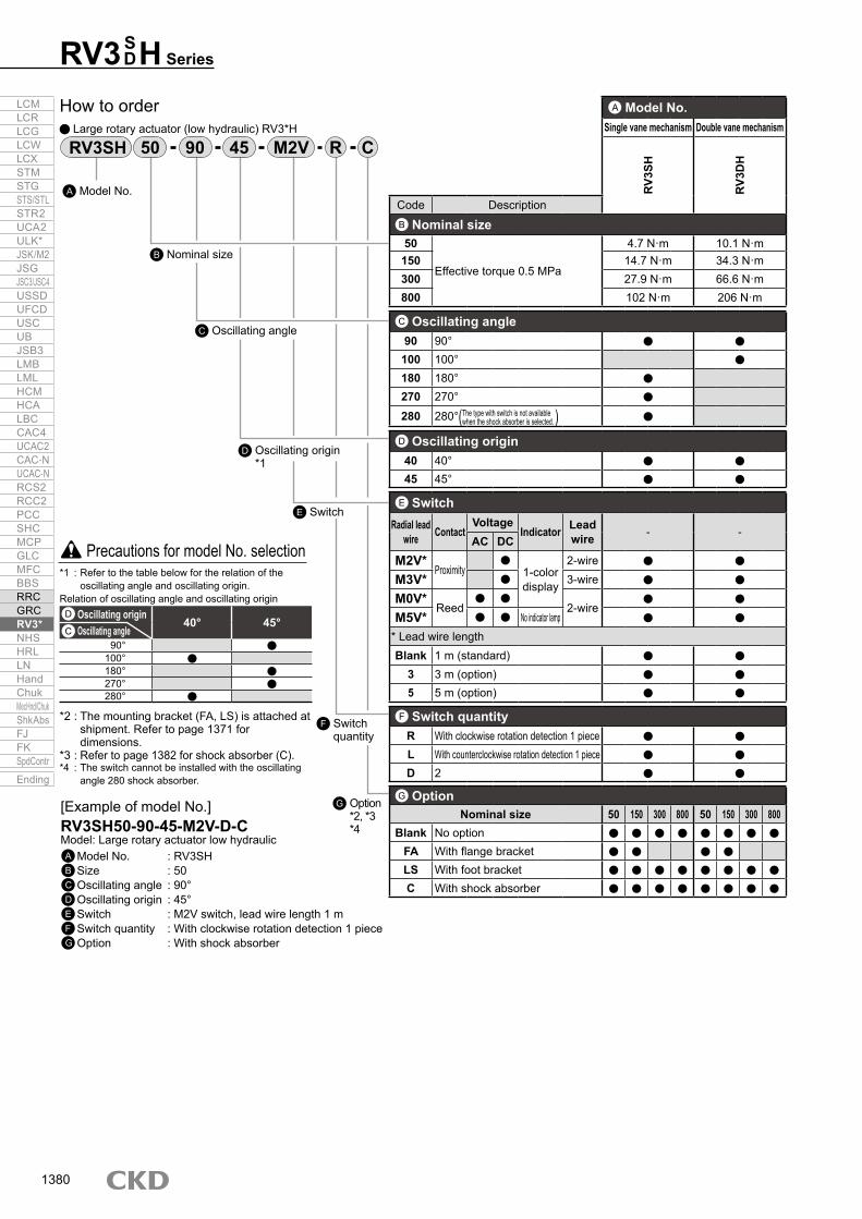
RV3 H SeriesSD
*1 : Refer to the table below for the relation of the oscillating angle and oscillating origin.
Relation of oscillating angle and oscillating origin
*2 : The mounting bracket (FA, LS) is attached at shipment. Refer to page 1371 for dimensions.
*3 : Refer to page 1382 for shock absorber (C).*4 : The switch cannot be installed with the oscillating
angle 280 shock absorber.
Precautions for model No. selection
[Example of model No.]RV3SH50-90-45-M2V-D-CModel: Large rotary actuator low hydraulicA Model No. : RV3SHB Size : 50C Oscillating angle : 90°D Oscillating origin : 45°E Switch : M2V switch, lead wire length 1 mF Switch quantity : With clockwise rotation detection 1 pieceG Option : With shock absorber
RV3SH M2V CR4550 90
A Model No.Single vane mechanism Double vane mechanism
RV3
SH
RV3
DH
Code DescriptionB Nominal size50
Effective torque 0.5 MPa
4.7 N·m 10.1 N·m150 14.7 N·m 34.3 N·m300 27.9 N·m 66.6 N·m800 102 N·m 206 N·m
C Oscillating angle90 90°
100 100°180 180°270 270°
280 280°( )D Oscillating origin40 40°45 45°
E SwitchRadial lead
wire ContactVoltage
Indicator Lead wire - -
AC DCM2V*
Proximity
1-color display
2-wire
M3V* 3-wire
M0V*Reed
2-wire
M5V* No indicator lamp* Lead wire lengthBlank 1 m (standard)
3 3 m (option)5 5 m (option)
F Switch quantityR With clockwise rotation detection 1 pieceL With counterclockwise rotation detection 1 pieceD 2
G OptionNominal size 50 150 300 800 50 150 300 800
Blank No optionFA With flange bracketLS With foot bracketC With shock absorber
The type with switch is not available when the shock absorber is selected.
How to order Large rotary actuator (low hydraulic) RV3*H
Model No.A
Nominal sizeB
Oscillating angleC
SwitchE
Switch quantity
F
Oscillating origin*1
D
Option *2, *3*4
G
D Oscillating origin40° 45°
C Oscillating angle90°
100°180°270°280°
LCMLCRLCGLCWLCXSTMSTGSTS/STLSTR2UCA2ULK*JSK/M2JSGJSC3/JSC4USSDUFCDUSCUBJSB3LMBLMLHCMHCALBCCAC4UCAC2CAC-NUCAC-NRCS2RCC2PCCSHCMCPGLCMFCBBSRRCGRCRV3*NHSHRLLNHandChukMecHnd/ChukShkAbsFJFKSpdContr
Ending
1380

90 M2VC RRVU50How to order switch unit
Code DescriptionA ModelRVU50 Applicable actuator: RV3S/D50RVU150 Applicable actuator: RV3S/D150RVU300 Applicable actuator: RV3S/D300RVU800 Applicable actuator: RV3S/D800
B UnitBlank Standard products
C With shock absorber
C Oscillating angle90 90°100 100°180 180°270 270°280 280° (“C” (for shock absorber) cannot be selected.)
D Switch model No.M2V*
Prox. 1-color display
2-wireM3V* 3-wireM0V*
Reed 2-wireM5V* Without indicator lamp
* Lead wire lengthBlank 1 m (standard)
3 3 m (option)5 5 m (option)
E Switch quantityR With clockwise rotation detection 1 pieceL With counterclockwise rotation detection 1 pieceD 2
ModelA
UnitB
Switch quantityE
Oscillating angleC
Switch model No.D
[Example of model No.]RVU50-C-90-M2V-RModel: Switch unitA Model : RV3S/D50B Unit : With shock absorberC Oscillating angle : 90°D Switch model No. : M2V switch, lead wire length 1 mE Switch quantity : With clockwise rotation detection 1 piece
Note: When the type for shock absorber is selected, the shock absorber body must be purchased separately.
Precautions for model No. selection
Dimensions
RV3 H SeriesHow to order
SD
Dimensions are the same as the large rotary actuator vane mechanism/standard RV3 SD Series. Refer to page 1369.
LCMLCRLCGLCWLCXSTMSTGSTS/STLSTR2UCA2ULK*JSK/M2JSGJSC3/JSC4USSDUFCDUSCUBJSB3LMBLMLHCMHCALBCCAC4UCAC2CAC-NUCAC-NRCS2RCC2PCCSHCMCPGLCMFCBBSRRCGRCRV3*NHSHRLLNHandChukMecHnd/ChukShkAbsFJFKSpdContr
Ending
1381

Shock absorber
RVC Series Torque size: 50/150/300/800 Absorbed energy: 2.9/9.8/19.6/58.8 J
Item RVCSize 50 150 300 800Load range kg·m2 0.098 0.294 0.588 1.961Allowable absorbed energy J 2.9 9.8 19.6 58.8Max. colliding angular speed rad/s 14.8 13.0 11.3 9.6Maximum energy capacity per minute *1 J/min 20 72 140 350Ambient temperature °C 5 (41°F) to 50 (122°F)Absorbing angle (single) rad 0.19 0.20 0.24 0.26Weight kg 0.24 0.42 0.78 1.62
Finger weight kg
90° 0.07 0.15 0.36 1.0100° 0.07 0.14 0.35 1.0180° 0.07 0.15 0.37 1.0270° 0.05 0.11 0.28 0.8280° 0.05 0.10 0.25 0.7
Model Applicable rotary actuatorRVC50 RV3*50RVC150 RV3*150RVC300 RV3*300RVC800 RV3*800
RVC50
*1 : Energy capacity per minute = absorbed energy × n times/min n: No. of times fingers contact cushion piston*2 : When using with the shock absorber, set the rotary actuator’s working pressure to 0.3 MPa and over.
BodyHow to order
Specifications
T90RVC50 Finger for shock absorber
ModelA
Oscillating angleB
Part (finger)C
Code DescriptionA Model
RVC50 For RV3*50RVC150 For RV3*150RVC300 For RV3*300RVC800 For RV3*800
B Oscillating angle90 90°100 100°180 180°270 270°280 280°
C Part (finger)T Finger for shock absorber
When a finger installed on the rotary actuator shaft hits the piston, the generated energy is converted to pressure (hydraulic pressure) on the back of the piston.This pressure energy becomes the thermal energy when it passes through the gap between the piston and cylinder bore and then the adjustment needle part, and is released into the air from the body surface. It will be consumed before the piston stops at the stroke end. The piston on the opposite side is pressurized by the spring force and returns to the origin.
1. Obtain the moment of inertia from the size of the load, and confirm that it is within the load range.
2. Check that the colliding angular speed is within the range.ω0 ≈ 1.2ωω0: Colliding angular speed (rad/s)ω: Average angular speed (rad/s)
3. Obtain collision energy from the load and colliding angular speed.E1 = 1/2Iω0
2
I: Moment of inertia (kg·m2)ω0: Colliding angular speed (rad/s)
Operational principle
Impact energy4. Obtain energy generated by the torque of the rotary actuator.
E2 = 1/2Tθ’T: Torque of rotary actuator (N·m)θ’: Shock absorber absorbing angle (per side) (rad)
5. Confirm that E1 + E2 is less than the max. absorbed energy.6. Obtain energy per minute from frequency.
Em=(E1+E2)×nn: No. of times fingers contact cushion piston.
Confirm that Em is less than or equal to the max. energy per minute.
FingerPiston
Adjusting needle
Pressurization spring
LCMLCRLCGLCWLCXSTMSTGSTS/STLSTR2UCA2ULK*JSK/M2JSGJSC3/JSC4USSDUFCDUSCUBJSB3LMBLMLHCMHCALBCCAC4UCAC2CAC-NUCAC-NRCS2RCC2PCCSHCMCPGLCMFCBBSRRCGRCRV3*NHSHRLLNHandChukMecHnd/ChukShkAbsFJFKSpdContr
Ending
1382

Dimensions (RVC 50/150/300)
Code A B C D E F G H J K L M N P Q R S T U V W Y Z AA BB CC DD EEModel No.RVC50 50.5 6 32 4.5 14 16 8.5 14.4 56.6 9.9 40 50 4 37 7.1 17 9.2 8 7.2 39 56 12.5 ø45 6.5 30 M6×12 34 8
RVC150 56.5 7.2 36 4.5 16 18 8.5 18.4 70.7 11.3 50 62 9.5 49 8.4 25.5 11.4 10 8 60.6 80 15 ø70 10 30 M8×16 46 12RVC300 62.5 7.2 42 4.5 16 21 12 22.5 91.9 12.7 65 87 8 61 14.2 33.2 14.1 12 12 69.2 95 22.5 ø80 15 30 M10×20 62 18
Code A B C D E F G H J K L M N P QModel No.RVC50 -90-T 23 10 16 13.7 10 1.2 2.5 10 M5 7 76 18 18.5 8 5RVC150-90-T 28 12 24 19.5 12 1.2 3.9 13 M6 7.5 102 20 23 10 5RVC300-90-T 40 18 35 30.5 14 1.2 5.4 19 M8 9 136 23.5 33.5 12 9
Code A B C D F G H J K L M N PModel No.RVC50 -100-T 23 10 16 13.5 1.2 2.5 10 M5 7 74 17.5 18.5 7RVC150-100-T 28 12 24 19.5 1.2 4 13 M6 9 102 20 23 10RVC300-100-T 40 18 35 30.5 1.2 5.5 19 M8 11 136 23.5 33.5 12
Material: S50C or equivalentMaterial: S50C or equivalent
(Unit: mm)
Note: Figure shows one mounting finger for 270˚.
RVC 50/150/300
Finger for shock absorber dimensions Oscillating angle 90° (oscillating origin 45°) Oscillating angle 100° (oscillating origin 40°)
RVC SeriesDimensions
YZ
Approximate stroke length AA
EE
L
KJ
L
U
DDWV
(BB°)
shaft centerRotary actuator
RS
PQ
NM
F
ED C
B A
Max. G
H
2-CC
Hexagon socket head cap screw for mounting rotary actuator
øT
K
P
M
5° GB
A
4.5 E
J
2-M4 depth 6Q
N
4.5
øL
F
DHC
B
A
N
G P K
M
F D LHC
J
LCMLCRLCGLCWLCXSTMSTGSTS/STLSTR2UCA2ULK*JSK/M2JSGJSC3/JSC4USSDUFCDUSCUBJSB3LMBLMLHCMHCALBCCAC4UCAC2CAC-NUCAC-NRCS2RCC2PCCSHCMCPGLCMFCBBSRRCGRCRV3*NHSHRLLNHandChukMecHnd/ChukShkAbsFJFKSpdContr
Ending
1383

Note) Model No. with options such as switch, valve, and shock absorber, etc., is listed on pages 1395 and 1396.
Finger for shock absorber dimensions (RVC 50/150/300) Oscillating angle 180° (oscillating origin 45°)
Oscillating angle 280° (oscillating origin 40°)
Oscillating angle 270° (oscillating origin 45°)
Oscillating angle 100° (with magnet)
Code A B C D E F G H J K L M N P QModel No.RVC50 -180-T 23 10 16 13.7 10 1.2 2.5 10 M5 7 38 18 18.5 8 5RVC150-180-T 28 12 24 19.5 12 1.2 3.9 13 M6 9 51 20 23 10 5RVC300-180-T 40 18 35 30.5 14 1.2 5.4 19 M8 11 68 23.5 33.5 12 9
Code A B C D F G H J K L M N PModel No.RVC50 -280-T 23 13 16 13.5 1.2 5 10 M5 7 37 20 4.5 10RVC150-280-T 28 16 24 19.5 1.2 8 13 M6 9 51 20 5 10RVC300-280-T 40 22 35 30.5 1.2 11 19 M8 11 68 24 6.5 12.5
Code A B C D E F G H J K L M N PModel No.RVC50 -270-T 23 13 16 13.7 10 1.2 2.6 10 M5 7 38 18 4.5 8RVC150-270-T 28 16 24 19.5 12 1.2 4 13 M6 9 51 20 5 10RVC300-270-T 40 22 35 30.5 14 1.2 5.5 19 M8 11 68 23.5 6.5 12
Code C H K L M N PModel No.RVU50-100-A1-C 26 10 8 74 18 8.5 8RVU150-100-A1-C 32 13 9 102 20 11 10RVU300-100-A1-C 48 19 11 136 23.5 15 12
Material: SCM435 or equivalent
Material: S50C or equivalent
Material: S50C or equivalent
Material: S50C or equivalent
RVC Series
F
H
G
Q
5°
2-M4 depth 6
5°
R L
4.5
4.5
QG E
J
D C
B
A
K
P
M
N
G
G
P
M4 depth 6
5°5°
R L 4.
5
E
J F
C
D
B
A
N
K
M
H
F
D
C
K
M
H
A
BR
L
G P
N
J øL
P
M
N
H
øC
K
LCMLCRLCGLCWLCXSTMSTGSTS/STLSTR2UCA2ULK*JSK/M2JSGJSC3/JSC4USSDUFCDUSCUBJSB3LMBLMLHCMHCALBCCAC4UCAC2CAC-NUCAC-NRCS2RCC2PCCSHCMCPGLCMFCBBSRRCGRCRV3*NHSHRLLNHandChukMecHnd/ChukShkAbsFJFKSpdContr
Ending
1384
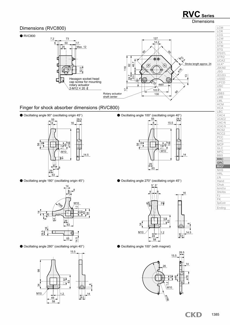
Dimensions (RVC800) RVC800
Finger for shock absorber dimensions (RVC800) Oscillating angle 90° (oscillating origin 45°)
Oscillating angle 180° (oscillating origin 45°) Oscillating angle 270° (oscillating origin 45°)
Oscillating angle 100° (oscillating origin 40°)
Oscillating angle 280° (oscillating origin 40°) Oscillating angle 100° (with magnet)
RVC SeriesDimensions
Stroke length approx. 24
shaft centerRotary actuator
Max. 12
130103.9
12714.2
27.5
9090
90
R60R35
32.5 11
8
5834
98
58
18
1782 46
.7
1320.6
24.7
25
7.26 50 17
73
55 55
29
29
63
63
29
55
4958
28.5
15.515.5
28.5
141.2
1.2
491.2
58
1426
29.5
16
14.5
M10
M10
R98
R98 18
63
8
14 8
2-M12×20 ℓ
Hexagon socket head cap screw for mountingrotary actuator
30°
5°
ø16
29.5 28.5
14.5M10
M10
M10
M10
16 15.5
14
ø196
ø78
ø46
ø196
196
58
32
63 834
4932
1.2
49 49
1429
.516
14.5
145°
5°
5° 5°8
88 8
18
1.2
1.2
32
32
32
32
63
8
LCMLCRLCGLCWLCXSTMSTGSTS/STLSTR2UCA2ULK*JSK/M2JSGJSC3/JSC4USSDUFCDUSCUBJSB3LMBLMLHCMHCALBCCAC4UCAC2CAC-NUCAC-NRCS2RCC2PCCSHCMCPGLCMFCBBSRRCGRCRV3*NHSHRLLNHandChukMecHnd/ChukShkAbsFJFKSpdContr
Ending
1385

RV3* Series
Item Proximity switchSR-*(-U)
Applications For programmable controller/relay/IC circuit/compact solenoid valvePower supply voltage 5 VDC to 30 VDCLoad voltage/current 5 to 30 VDC, 200 mA or lessCurrent consumption 20 mA or less with 24 VDCInternal voltage drop 1.5V or lessIndicator lamp LED (Lit when ON)Leakage current 10 μA or lessLead wire length 1 m (oil resistant vinyl cabtyre cable 4-conductor 0.2 mm2)Shock resistance 490 m/s2
Insulation resistance 100 MΩ or more with 500 V meggerWithstand voltage No failure after 1 minute of 1,000 VAC application.Ambient temperature 5 to 60°CDegree of protection IEC standards IP67, JIS C0920 (water tight)
* mark indicates a rotary actuator size. (3, 10, 20)
SpecificationsSwitch unit: Compact standard with valve
How to order How to order switch unit
USR-3 45RV3S 90
ModelA
Oscillating angleB
C Oscillating origin
D Lead wire direction
Precautions for model No. selection*1 : The type with switch is not available for the
axial port position direction “S”.
[Example of model No.]RV3S-SR-3-90-45-UModel: Switch unitA Model : For RV3S3B Oscillating angle : 90°C Oscillating origin : 45°D Lead wire direction : Radial lead wire
Code DescriptionA ModelSR-3 Applicable actuator: RV 33
SR-10 Applicable actuator: RV 310SR-20 Applicable actuator: RV 320SR-30 Applicable actuator: RV 330
B Oscillating angle90 90°180 180°270 270°
SDSDSDSD
C Oscillating originModel SR-3 SR-10 SR-20 SR-30
45 45°90 90°
D Lead wire directionBlank With axial lead wire switch
U With radial lead wire switch
LCMLCRLCGLCWLCXSTMSTGSTS/STLSTR2UCA2ULK*JSK/M2JSGJSC3/JSC4USSDUFCDUSCUBJSB3LMBLMLHCMHCALBCCAC4UCAC2CAC-NUCAC-NRCS2RCC2PCCSHCMCPGLCMFCBBSRRCGRCRV3*NHSHRLLNHandChukMecHnd/ChukShkAbsFJFKSpdContr
Ending
1386

RV3* SeriesSwitch unit
Note: Use same power supply for switch and load.
Switch wiring procedureSwitch internal wiring diagram
The switch is fixed, and the position cannot be adjusted.
Hysteresis and operational range of switch
Rotary actuator body Operational range HysteresisRV3 -3
15°±7° 3° or lessRV3 -10
RV3 -20
SDSDSD
* Switch unit can be installed onto rotary actuator without switch.RV3S1 with switch is not available.
Configurations Rotor set screw Rotor body Switch unit mounting screw Switch unit body
Switch unit configurations
Switch unit
Blue wire (-)
Black wire (output)
White wire (output)
Brown wire (+)
Switch
main circuitSwitch
Load
Load
White (oscillating origin side detection)
Black (oscillating end detection)
Power supply 4.5 to 30 VDC
Blue
Brown
SR
Oscillating angle
Oscillating originOscillating end
Hysteresis
Switch return position
Switch operation position
Hysteresis
Switch return position
Shaft
Switch operational range
Switch operation position
Rotary actuator
Rotor body
Switch unit body
Switch unit mounting screw
Rotor set screw
main circuit
LCMLCRLCGLCWLCXSTMSTGSTS/STLSTR2UCA2ULK*JSK/M2JSGJSC3/JSC4USSDUFCDUSCUBJSB3LMBLMLHCMHCALBCCAC4UCAC2CAC-NUCAC-NRCS2RCC2PCCSHCMCPGLCMFCBBSRRCGRCRV3*NHSHRLLNHandChukMecHnd/ChukShkAbsFJFKSpdContr
Ending
1387

RV3* Series
Item Proximity switchFR-*(-U)
Applications Programmable controller, relay, IC circuitPower supply voltage 5 VDC to 30 VDCLoad voltage 5 VDC to 30 VDCLoad current 5 mA to 200 mA
Current consumption
24 VDC: 20 mA or less,12 VDC: 10 mA or less,
5 VDC: 4 mA or less
Internal voltage drop 1.5 V or lessIndicator lamp LED (Lit when ON)Leakage current 10 μA or lessLead wire length 1.0 m (oil resistant black 3-conductor cable)Shock resistance 490 m/s2
Insulation resistance 100 MΩ or more with 500 V meggerWithstand voltage No failure after 1 minute of 1,500 VAC application.Ambient temperature 5 to 60°CDegree of protection IEC standards IP67, JIS C0920 (water tight)
Switch Operational range HysteresisCT-3 23°±7° Approx. 2°
Switch wiring procedureSwitch internal wiring diagram
Hysteresis of switch and operational range
* mark indicates rotary actuator size. (3, 10, 20, 30)
Switch unit: Compact oscillating angle variable Specifications
UFR-3RV3S
How to order Switch unit
ModelA
Lead wire directionB[Example of model No.]RV3S-FR-3-UModel: Switch unit angle variableA Model : For RV3SA3B Lead wire direction : Radial lead wire
Code DescriptionA Model
FR-3 Applicable actuator: RV3S DA3
FR-10 Applicable actuator: RV3S DA10
FR-20 Applicable actuator: RV3S DA20
FR-30 Applicable actuator: RV3S DA30
B Lead wire directionBlank With axial lead wire switch
U With radial lead wire switch
-
+
-
+
-
+
Blue wire (power supply -)
Black wire (output)
Brown wire (power supply +)BlueBlackBrown
DC power for switch
DC power for load 30 VDC or less
DC power for switch, load
BlueBlackBrown
Load
LoadSwitch
Switch
Switc
hm
ain
circ
uit
LCMLCRLCGLCWLCXSTMSTGSTS/STLSTR2UCA2ULK*JSK/M2JSGJSC3/JSC4USSDUFCDUSCUBJSB3LMBLMLHCMHCALBCCAC4UCAC2CAC-NUCAC-NRCS2RCC2PCCSHCMCPGLCMFCBBSRRCGRCRV3*NHSHRLLNHandChukMecHnd/ChukShkAbsFJFKSpdContr
Ending
1388

RV3* SeriesSwitch unit
Oscillating angle Switch combination30° to 186° Combination A187° to 270° Combination B
When the oscillating angle variable RV3*A Series with switch is selected, the switch unit is attached with the product. Install and adjust the angle setting stopper at the set angle, and then install the switch with the following combination.
Mounting the switch unit bodyMount onto the rotary actuator body using the switch case mounting screws. Refer to table below for the tightening torque.
Switch position adjustmentLoosen the switch adjust screw, set the switch’s max. sensitivity position to the angle scale which corresponds to the rotary actuator’s set angle, and then fix the switch. Tighten with a tightening torque of 40 to 50 N·cm. Since the angle scale is a guide, confirm that the LED turns ON when making the final adjustment. Switch replacementRemove the switch adjusting screw and plate fixing screw, and then replace the switch.When fixing, clamp with a force of 40 to 50 N·cm.Assemble the switch following the removal steps in reverse, and always adjust the switch position.
Oscillating angle and switch mounting position
Switch unit assembly and switch adjustment method
SDSDSDSD
Model No. Tightening torque (N·m)For RV3 A3 0.06 to 0.2For RV3 A10 0.1 to 0.2For RV3 A20
0.2 to 0.3For RV3 A30
Combination B
Combination A
270°
Plate fixing screw
Angle scale
Rotary actuator
Magnet holderMounting screw
Magnet holder
Switch case
Switchadjusting screw
Switch unit configurations
Magnet
Mounting screwSwitch case
Max. sensitivity position
Max. sensitivity positionMax. sensitivity positionPort position
CT-3RCT-3L
180°
Min. setting angle 24°
Max. sensitivity positionMax. sensitivity position
Port positionCT-3LCT-3R
LCMLCRLCGLCWLCXSTMSTGSTS/STLSTR2UCA2ULK*JSK/M2JSGJSC3/JSC4USSDUFCDUSCUBJSB3LMBLMLHCMHCALBCCAC4UCAC2CAC-NUCAC-NRCS2RCC2PCCSHCMCPGLCMFCBBSRRCGRCRV3*NHSHRLLNHandChukMecHnd/ChukShkAbsFJFKSpdContr
Ending
1389

RV3* Series
Item Proximity 2-wire Proximity 3-wire Reed 2-wireM2V M3V M0V M5V
Applications Dedicated for programmable controller
For programmable controller,relay, IC circuit, compact solenoid valve For programmable controller, relay For programmable controller, relay, IC circuit
(without indicator lamp), serial connectionPower supply voltage — 4.5 to 28 VDC —
Load voltage/current 10 to 30 VDC,5 to 30 mA
30 VDC or less, 100 mA or less
5 to 50 mA with 12/24 VDC,7 to 20 mA with 110 VAC
50 mA or less with 5/12/24 VDC,20 mA or less with 110 VAC
Current consumption — At 24 VDC10 mA or less (when ON) —
Internal voltage drop 4 V or less 0.5 V or less 2.4 V or less 0 VIndicator lamp LED (Lit when ON) Without indicator lamp Leakage current 1 mA or less 10 μA or less 0 mA
Lead wire length Oil resistant vinyl cabtyre cable 2-conductor 0.2 mm2
Oil resistant vinyl cabtyre cable 3-conductor 0.15 mm2
Oil resistant vinyl cabtyre cable 2-conductor 0.2 mm2
Shock resistance 980 m/s2 294 m/s2
Insulation resistance 100 MΩ and over with 500 VDC meggerWithstand voltage No failure after 1 minute of 1,000 VAC application.Ambient temperature -10 to +60°CDegree of protection IEC Standard IP67, JIS C0920 (water-tight), oil resistanceWeight g 1 m:22 3 m:57 5 m:93
How to order* M0 switch can be used for 24 VAC and 48 VAC within load current range of 7 to 20 mA.
SpecificationsLarge switch unit: Standard/with valve/low hydraulic
1 m 1 m 1 m
90 M2VC RRVU50
Switch model No.D
Switch quantityE
Oscillating angleC
Unit
Model
Switch unit
B
A
Code DescriptionA ModelRVU50 Applicable actuator: RV3S/D50RVU150 Applicable actuator: RV3S/D150RVU300 Applicable actuator: RV3S/D300RVU800 Applicable actuator: RV3S/D800
B UnitBlank Standard products
C With shock absorber
C Oscillating angle90 90°100 100°180 180°270 270°280 280° (“C” (with shock absorber) cannot be selected.)
D Switch model No.Radial lead
wire Conta
ct Voltage Indicator Lead wireAC DCM2V*
Prox.
1-color display
2-wireM3V* 3-wireM0V* Reed
2-wireM5V* Without indicator lamp* Lead wire lengthBlank 1 m (standard)
3 3 m (option)5 5 m (option)
E Switch quantityR With clockwise rotation detection 1 pieceL With counterclockwise rotation detection 1 pieceD 2
Precautions for model No. selection
[Example of model No.]RVU50-C-90-M2V-RModel: Switch unitA Model : RV3S/D50B Unit : With shock absorberC Oscillating angle : 90°D Switch model No. : M2V switch, lead wire length 1 mE Switch quantity : With clockwise rotation detection 1 piece
Note: When the type for shock absorber is selected, the shock absorber body must be purchased separately.
LCMLCRLCGLCWLCXSTMSTGSTS/STLSTR2UCA2ULK*JSK/M2JSGJSC3/JSC4USSDUFCDUSCUBJSB3LMBLMLHCMHCALBCCAC4UCAC2CAC-NUCAC-NRCS2RCC2PCCSHCMCPGLCMFCBBSRRCGRCRV3*NHSHRLLNHandChukMecHnd/ChukShkAbsFJFKSpdContr
Ending
1390

RV3* SeriesSwitch unit
M2V M3V M0V M5V
Switch internal circuit diagram
Item Operational rangeModel No. M2V, M3V M0V, M5V
RV3S50, RV3D50 Approx. 40° Approx. 25°RV3S150, RV3D150 Approx. 25° Approx. 15°RV3S300, RV3D300 Approx. 25° Approx. 15°RV3S800, RV3D800 Approx. 25° Approx. 15°
When installing the switch unit afterwards, if the clearance between the switch and magnet exceeds the range on the following drawing, adjust the clearance with a bending bracket.
Switch adjustment methodOperational range of switch
Blue wire (-)
Brown wire (+)
Blue wire (power supply -)
Black wire (output)
Brown wire (power supply +) Blue wire (-)Brown wire (+) Blue wireBrown wire
main
circu
itS
witc
h
mai
n ci
rcui
tS
witc
h
Magnet
Switch operation position
Switch operational range
Detecting position
(Tightening torque 0.5 to 0.7 N·m)
M type switch
Set screw
Bracket
Magnet
1 to 2
LCMLCRLCGLCWLCXSTMSTGSTS/STLSTR2UCA2ULK*JSK/M2JSGJSC3/JSC4USSDUFCDUSCUBJSB3LMBLMLHCMHCALBCCAC4UCAC2CAC-NUCAC-NRCS2RCC2PCCSHCMCPGLCMFCBBSRRCGRCRV3*NHSHRLLNHandChukMecHnd/ChukShkAbsFJFKSpdContr
Ending
1391

RV3* Series
Finger for shock absorber with magnetFingerMagnetMagnet holderHexagon socket head cap screwPan head machine screwSpring washerBase bracketBase bracketMounting bracket for M type switchM type switch installation bandMounting bracketCross-recessed pan head machine screwWith shock absorber Switch mounting bracketLS bracketHolderPan head machine screwSpring washerM type switch
Finger with magnetFingerBossMagnetPan head machine screwNutBase bracketSmall base bracket binding screwMounting bracket for M type switchM type switch installation bandMounting bracketCross-recessed pan head machine screwSwitch mounting bracketLS bracketHolderPan head machine screwSpring washerM type switch
Switch unit (standard)
ConfigurationsSwitch unit standard (standard)RVU-
Rotary actuator with switch
(Note) Shock absorber body is not included in switch unit.(Refer to page 1382 for model No. of shock absorber.)
When purchasing switch other than standard switch unit, refer to pages 1395 and 1396 for repair parts kit.The rotary actuator with switch can be assembled by attaching the switch unit to the rotary actuator without switch.
Switch unit (With shock absorber) configurations
Switch unit configurations RVU50/150/300
RVU800
Binding machine screw
Finger with magnet
Bracket for M type
SW bracket(Including holding plate)
Base bracketM type switch
Switch unit (with shock absorber)RVU-C-
50
300RVC150
Shock absorber
Finger for shock absorber with magnet
Bracket for M type
M type switchSW bracket with shock absorber(Including holding plate)
Switc
h +
Brac
ket
with
switc
h
Switc
h +
Brac
ket
with
switc
h
Switch unit configurations Switch unit configuration with shock absorber
Magnet arm
Magnet arm fixing screwMagnet mounted holder
Shock absorber mounting bolt
Switch mounting bracketM type switch
Port direction
With magnetFinger for shock absorber
Shock absorber body (with switch)
Lock nut
Base bracket mounting screw
Switch mounting bracketM type switch
Base bracket
(Attached with magnet arm)(Attached with finger for shock absorber with magnet)
(Attached with shock absorber body)
(Attached with shock absorber body)
(Attached with magnet arm)
(Attached with base bracket)
(Integrated into base bracket)
LCMLCRLCGLCWLCXSTMSTGSTS/STLSTR2UCA2ULK*JSK/M2JSGJSC3/JSC4USSDUFCDUSCUBJSB3LMBLMLHCMHCALBCCAC4UCAC2CAC-NUCAC-NRCS2RCC2PCCSHCMCPGLCMFCBBSRRCGRCRV3*NHSHRLLNHandChukMecHnd/ChukShkAbsFJFKSpdContr
Ending
1392