iDirect at MWC 15: Satellite – bringing you up to speed for 3G and 4G rural coverage

Rural E-mail System
for the
Sumbandila Satellite
Adrian Cooke
Thesis presented in partial fulfilment of the requirements for the degree
Master of Science in Electronic Engineering
at the University of Stellenbosch
Supervisor: Dr G-J van Rooyen
March 2007


Declaration
I, the undersigned, hereby declare that the work contained in this thesis is
my own original work and that I have not previously in its entirety or in
part submitted it at any university for a degree.
Signature Date

Abstract
Keywords: digital signal processing, OSI layer, network protocols, embedded systems,
satellite technology
This thesis describes the design and implementation of a rural e-mail system for the Sum-
bandila satellite. The rural e-mail system was developed during a project sponsored by
the Department of Communications of the South African government. The complete Open
Systems Interconnect (OSI) layer structure of the protocol architecture used on the satellite
hardware and software is described. The equivalent implementation of the OSI layer on the
ground station hardware is given. This includes the adaptation of the soundmodem Open
Source Software modem to work for the e-mail system’s OSI layer. The design of the Ap-
plication Layer e-mail system is described and the implementation of this design using the
Python, Korn Shell and C programming environments is also given. The procedures used to
test the system for reliability and the use of a database to create detailed logs of the e-mail
system is shown to have generated a reliable system that is easily maintained. A critical
evaluation of the system is provided in the last chapter.
i

Opsomming
Sleutelwoorde: Syferseinverwerking, OSI-lae, netwerkprotokolle, toegewyde stelsels, satel-
liettegnologie
Hierdie tesis beskryf die ontwerp en implementering van ’n plattelandse e-posstelsel vir die
Sumbandila satelliet. Die plattelandse e-posstelsel is ontwikkel in opdrag van die Departe-
ment van Kommunikasie van die Suid-Afrikaanse regering. Die volledige Open Systems
Interconnect (OSI) laagstruktuur van die protokol-argitektuur wat in die satelliet se ap-
paratuur en programmatuur gebruik is, word beskryf. Die ekwivalente implementering
van die OSI-laag op die grondstasie-apparatuur word gegee, insluitende die aanpassing van
soundmodem, ’n oopbronkode sagteware-modem. Hierdie sagteware-modem word gebruik in
die e-posstelsel se fisiese laag. Die ontwerp van die toepassingslaag van die e-posstelsel word
beskryf, asook die implementering van hierdie ontwerp met behulp van Python, die Korn-
interpreteerder en C. Die prosedures waarvolgens stelselbetroubaarheid getoets is, en die
gebruik van ’n databasis om noukeurige joernale van e-postransaksies te hou, demonstreer
dat ’n betroubare, onderhoubare stelsel gemplementeer is. In die laaste hoofstuk word die
stelsel krities geevalueer.
ii

Acknowledgements
• Firstly I would like to thank Dr Gert-Jan van Rooyen for his guidance as my supervisor.
He has helped me in many situations with his interesting comments that allowed me
to look at the project from a different perspective.
• Dr Riaan Wolhuter’s help in the management of the project was much appreciated.
His experience helped me out in difficult situations that I am not accustomed to.
• I would like to thank Prof. Johan Lourens for bringing me into the project and the
support he has given me over the years. The project was a very enriching experience
and helped me grow as person.
• Retief Gerber was a great help in developing some of the software for the satellite when
the deadlines got close.
• I would like to thank the people at SunSpace for the willing help they gave me when
working with their hardware and software. Special thanks to Otto Strydom, Francois
Retief and Gregor Dreijer for dealing with my many e-mails.
• Lastly I would like to thank my parents for their quiet manner of allowing me to get
on with my studies. I would not have been able to get to where I am if it were not for
their support in all facets of my life.
iii

Contents
Nomenclature viii
Terms of Reference x
1 Introduction 1
1.1 Project Background . . . . . . . . . . . . . . . . . . . . . . . . . . . . . . . . 1
1.2 Purpose of the Project . . . . . . . . . . . . . . . . . . . . . . . . . . . . . . 3
1.3 Structure of the Thesis . . . . . . . . . . . . . . . . . . . . . . . . . . . . . . 3
2 OSI Layer Constraints 5
2.1 OSI Model . . . . . . . . . . . . . . . . . . . . . . . . . . . . . . . . . . . . . 5
2.2 Physical Layer . . . . . . . . . . . . . . . . . . . . . . . . . . . . . . . . . . . 6
2.2.1 The VUCU Modem . . . . . . . . . . . . . . . . . . . . . . . . . . . . 7
2.3 Data-Link Layer . . . . . . . . . . . . . . . . . . . . . . . . . . . . . . . . . . 8
2.4 Transport and Network Layer . . . . . . . . . . . . . . . . . . . . . . . . . . 9
2.5 Application Layer . . . . . . . . . . . . . . . . . . . . . . . . . . . . . . . . . 11
3 OSI Layer System Design 12
3.1 Physical and Data-Link Layer . . . . . . . . . . . . . . . . . . . . . . . . . . 12
3.2 Transport and Network Layer . . . . . . . . . . . . . . . . . . . . . . . . . . 17
3.3 Application Layer . . . . . . . . . . . . . . . . . . . . . . . . . . . . . . . . . 18
3.3.1 NFS . . . . . . . . . . . . . . . . . . . . . . . . . . . . . . . . . . . . 18
3.3.2 TFTP . . . . . . . . . . . . . . . . . . . . . . . . . . . . . . . . . . . 19
4 E-mail System Design 22
4.1 Components of the System . . . . . . . . . . . . . . . . . . . . . . . . . . . . 22
4.1.1 Ground Station . . . . . . . . . . . . . . . . . . . . . . . . . . . . . . 22
4.1.2 Satellite . . . . . . . . . . . . . . . . . . . . . . . . . . . . . . . . . . 23
4.1.3 Administration Files . . . . . . . . . . . . . . . . . . . . . . . . . . . 24
4.2 Design Choices . . . . . . . . . . . . . . . . . . . . . . . . . . . . . . . . . . 24
4.3 Flow Charts of the Different Components . . . . . . . . . . . . . . . . . . . . 25
4.3.1 Download . . . . . . . . . . . . . . . . . . . . . . . . . . . . . . . . . 25
4.3.2 Upload . . . . . . . . . . . . . . . . . . . . . . . . . . . . . . . . . . . 28
4.4 Typical File Transfer Sequences . . . . . . . . . . . . . . . . . . . . . . . . . 29
iv
CONTENTS v
5 E-mail System Implementation 34
5.1 Overview . . . . . . . . . . . . . . . . . . . . . . . . . . . . . . . . . . . . . . 34
5.1.1 File Integrity and Security . . . . . . . . . . . . . . . . . . . . . . . . 35
5.1.2 TFTP and NFS setup . . . . . . . . . . . . . . . . . . . . . . . . . . 35
5.1.3 List File Formats . . . . . . . . . . . . . . . . . . . . . . . . . . . . . 36
5.2 Satellite . . . . . . . . . . . . . . . . . . . . . . . . . . . . . . . . . . . . . . 36
5.2.1 Administration Software . . . . . . . . . . . . . . . . . . . . . . . . . 36
5.2.2 Ground Station Selection Software . . . . . . . . . . . . . . . . . . . 38
5.2.3 E-mail System Software . . . . . . . . . . . . . . . . . . . . . . . . . 39
5.3 Ground Station . . . . . . . . . . . . . . . . . . . . . . . . . . . . . . . . . . 42
5.3.1 Administration Scripts . . . . . . . . . . . . . . . . . . . . . . . . . . 43
5.3.2 User Interface . . . . . . . . . . . . . . . . . . . . . . . . . . . . . . . 43
5.3.3 E-mail System Scripts . . . . . . . . . . . . . . . . . . . . . . . . . . 44
6 Test Environment and System Reliability 47
6.1 Test Environment . . . . . . . . . . . . . . . . . . . . . . . . . . . . . . . . . 47
6.1.1 Ethernet . . . . . . . . . . . . . . . . . . . . . . . . . . . . . . . . . . 48
6.1.2 Audio Frequency . . . . . . . . . . . . . . . . . . . . . . . . . . . . . 49
6.1.3 Radio Frequency . . . . . . . . . . . . . . . . . . . . . . . . . . . . . 49
6.2 Structural Testing . . . . . . . . . . . . . . . . . . . . . . . . . . . . . . . . . 50
6.2.1 C Programs . . . . . . . . . . . . . . . . . . . . . . . . . . . . . . . . 50
6.2.2 Python Scripts . . . . . . . . . . . . . . . . . . . . . . . . . . . . . . 51
6.2.3 KSH Scripts . . . . . . . . . . . . . . . . . . . . . . . . . . . . . . . . 54
6.3 Integration Testing . . . . . . . . . . . . . . . . . . . . . . . . . . . . . . . . 55
7 Maintenance 57
7.1 System Logging . . . . . . . . . . . . . . . . . . . . . . . . . . . . . . . . . . 57
7.1.1 Ground Station . . . . . . . . . . . . . . . . . . . . . . . . . . . . . . 57
7.2 System Documentation . . . . . . . . . . . . . . . . . . . . . . . . . . . . . . 59
8 Test Results on the Integrated System 61
8.1 Integration Test Results . . . . . . . . . . . . . . . . . . . . . . . . . . . . . 61
8.2 ATFTP vs NFS . . . . . . . . . . . . . . . . . . . . . . . . . . . . . . . . . . 63
8.3 Transmission and Execution Times . . . . . . . . . . . . . . . . . . . . . . . 67
9 Conclusion 69
9.1 Summary of the conducted work . . . . . . . . . . . . . . . . . . . . . . . . . 69
9.2 Recommendations . . . . . . . . . . . . . . . . . . . . . . . . . . . . . . . . . 70
9.3 Final Remarks . . . . . . . . . . . . . . . . . . . . . . . . . . . . . . . . . . . 70
Bibliography 72

List of Figures
1.1 The rural e-mail network layout. . . . . . . . . . . . . . . . . . . . . . . . . . 2
2.1 OSI model of the network architecture. . . . . . . . . . . . . . . . . . . . . . 5
2.2 Structure of a Higher-Level Data Link Control (HDLC) frame. . . . . . . . . 8
2.3 Structure of the SunSpace custom protocol frame in a HDLC frame. . . . . . 9
2.4 Satellite block diagram of the system layout. . . . . . . . . . . . . . . . . . . 10
3.1 Fast Fourier Transform of the soundmodem audio signal generated with a sam-
pling frequency of 14400 Hz . . . . . . . . . . . . . . . . . . . . . . . . . . . 14
3.2 Fast Fourier Transform of the soundmodem audio signal generated with a sam-
pling frequency of 44100 Hz. . . . . . . . . . . . . . . . . . . . . . . . . . . . 15
3.3 Fast Fourier Transform of the VUCU audio signal sampled at 44100 Hz. . . . 17
3.4 Summary of the e-mail system OSI layer structure for the satellite and ground
stations. . . . . . . . . . . . . . . . . . . . . . . . . . . . . . . . . . . . . . . 21
4.1 The satellite download flow chart. . . . . . . . . . . . . . . . . . . . . . . . . 26
4.2 The ground station download flow chart. . . . . . . . . . . . . . . . . . . . . 27
4.3 The ground station upload flow chart. . . . . . . . . . . . . . . . . . . . . . . 28
4.4 The satellite upload flow chart. . . . . . . . . . . . . . . . . . . . . . . . . . 31
4.5 E-mail transfer upload example. . . . . . . . . . . . . . . . . . . . . . . . . . 32
4.6 E-mail transfer download example. . . . . . . . . . . . . . . . . . . . . . . . 33
5.1 The control software flow chart. . . . . . . . . . . . . . . . . . . . . . . . . . 40
6.1 Test setup block diagram. . . . . . . . . . . . . . . . . . . . . . . . . . . . . 48
8.1 NFS communication times for different bit error rates (BER×10−5). . . . . . 64
8.2 ATFTP communication times for different bit error rates (BER×10−5). . . . 65
vi

List of Tables
3.1 Bit error rate when different sampling frequencies are used in soundmodem. . 16
4.1 Domain and sub-domain definition. . . . . . . . . . . . . . . . . . . . . . . . 22
5.1 File structure of the different list files and acknowledgement files. . . . . . . 36
8.1 Test results for integration tests over the different links. . . . . . . . . . . . . 62
8.2 Transfer times (seconds) for files of different sizes (kB) at a BER equal to
1 × 10⁻⁵ using NFS and ATFTP. . . . . . . . . . . . . . . . . . . . . . . . . 66
8.3 Satellite script execution times. . . . . . . . . . . . . . . . . . . . . . . . . . 67
8.4 GSCommand execution times with files to transfer. . . . . . . . . . . . . . . . . 68
vii

Nomenclature
Acronyms
AC Alternating Current.
AF Audio Frequency.
ALSA Advanced Linux Sound Architecture.
AMSAT The Radio Amateur Satellite Corporation.
API Application Programming Interface.
APRN Amateur Packet Radio Network.
ATFTP Advanced Trivial File Transfer Protocol.
BER Bit Error Rate.
CAN Controller Area Network.
CRC Cyclic Redundancy Check.
DC Direct Current.
ECC Error Correction Code.
FM Frequency Modulation.
FTP File Transfer Protocol.
GPL General Public License.
GSE-EI Ground Support Equipment Ethernet Interface.
HDLC High-Level Data Link Control.
ICASA Independent Communications Authority of South Africa.
IF Intermediate Frequency.
IMAP Internet Message Access Protocol.
IP Internet Protocol.
ISO International Organisation for Standardization.
ITU International Telecommunications Union.
KISS Keep It Simple, Stupid.
KSH Korn Shell.
LSFR Linear Shift Feedback Register.
NFS Network File System.
OBC On-Board Computer.
OSCAR Orbital Satellite Carrying Amateur Radio.
OSI Open Systems Interconnection.
POP Post Office Protocol.
viii
NOMENCLATURE ix
POSIX Portable Operating System Interface.
RF Radio Frequency.
RISC Reduced Instruction Set Computer.
SEU Single Event Upset.
SHA-1 Secure Hash Algorithm version 1.
SLIP Serial Line Protocol.
SMTP Simple Mail Transfer Protocol.
SUNSAT Stellenbosch University Satellite.
TCP Transmission Control Protocol.
TFTP Trivial File Transfer Protocol.
TNC Terminal Node Controller.
UDP User Datagram Protocol.
UHF Ultra-High Frequency.
VCO Voltage Controlled Oscillator.
VHF Very-High Frequency.
VUCU VHF-UHF Communication Unit.
Variables
symbol description
baud The number of times a signal changes per second.
Commonly used to describe the number of symbols per second.
Hz Hertz
Ps Packet success rate.
Pn Probability of no errors.

Terms of Reference
The project on which this thesis is based was commissioned by the Department of Commu-
nications of South Africa as client, and the University of Stellenbosch as contractors. The
client requirement was the development of a low-bandwidth data relay system that could be
used as for short message exchange between rural and urban areas.
The specific constraints of the project were the following:
• All satellite hardware was to be supplied by Sun Space and Information Systems. The
ordering and manufacture of the hardware was to run in parallel with the project
development, and limited hardware would be available initially.
• No custom development or modification of satellite hardware was to be performed.
• A pair of communications frequencies were to be allocated by the Independent Com-
munications Authority of South Africa (ICASA). The allocation process was to run in
parallel with the project development, and a specific allocation of frequencies would
not be available for the first few months of the project.
x

Chapter 1
Introduction
1.1 Project Background
This project describes the design and implementation of the rural e-mail system that was
commissioned by the Department of Communications of the South African Government to
form part of the Sumbandila Satellite. Sumbandila means “lead the way” in the Thsivenda
language [7]. The satellite project was commissioned in 2006 to foster technological inno-
vation in South Africa. The design and implementation of the satellite is performed by the
University of Stellenbosch and Sun Space and Information Systems (Pty) Ltd (SunSpace).
SunSpace is a provider of satellite technology and the related systems to the aerospace
industry. The satellite is designed to have a life span of 3 years in orbit [7].
The Sumbandila satellite has several payloads on board. There is an advanced imaging
system. The imaging system will be used for the monitoring and management of disasters
such as floods, oils spills and fires [11] for example. The imager is going to have a ground
resolution of 6.25 m when orbiting at 500 km from the surface of the earth. The imager has
a matrix sensor to take low resolution snapshots. The imager will be able to be positioned
for earth image acquisition using a real time joystick system controlled by a ground station
operator [7].
There is going to be an experimental payload on the satellite. The experimental payload
is designed and administered by the University of Stellenbosch. There are several different
components of the experimental payload [24]:
• The radio amateur satellite corporation of South Africa (SA-AMSAT) is placing an
amateur radio service on the experimental payload. The amateur radio service will be
able to operate in digipeater, parrot and voice beacon mode.
• The Nelson Mandela Metropolitan University is placing a string vibration experiment
on the experimental payload. The primary goal of the experiment is to determine the
non-linear effects of string dynamics in micro-gravity.
• University of KwaZulu-Natal is placing an experiment on the payload to measure
the Earth’s magnetosphere. The goal of the experiment is to measure atmospheric
1

1.1 — Project Background 2
phenomena below 30kHz.
• The University of Stellenbosch is placing a software-defined radio experiment and an
experiment to measure the effects of radiation on satellite electronics on the experi-
mental payload
The e-mail system is an independent payload on the satellite which is designed and
implemented by the University of Stellenbosch using SunSpace hardware.
Ground Station
Gateway Ground Station
Sumbandila Satellite
Domain .sumbandila.co.za
JHB
PE
STBCPT
BFN
Greater Internet
Figure 1.1: The rural e-mail network layout [25].
The primary objective of the e-mail system is to provide a global e-mail facility, irrespec-
tive of user position, but with the understanding that users will be mobile [27]. Figure 1.1
shows the layout of the rural e-mail network that will be used to achieve this functionality.
There are going to be several rural ground stations that do not have access to the Internet.
The rural ground stations will be dispersed throughout South Africa. The rural ground
stations should be able to communicate with the greater Internet by e-mail.
The ground stations are able to communicate with the Sumbandila satellite. The satellite
is to operate as a relay service between the ground stations and the gateway ground stations.
1.2 — Purpose of the Project 3
Gateway ground stations have access to the greater Internet and can relay messages from
the rural e-mail network to the greater Internet.
The Sumbandila satellite is designed to have a polar orbit. The satellite is to pass over
South Africa four times a day and this is the only period when the ground stations will be
able to communicate with the satellite. The other payloads on the satellite will also have to
communicate with the central control ground station when the satellite passes over South
Africa. The passes over South Africa will have to be shared between the different payloads
on the satellite because the different payloads are unable to communicate to the ground at
the same time.
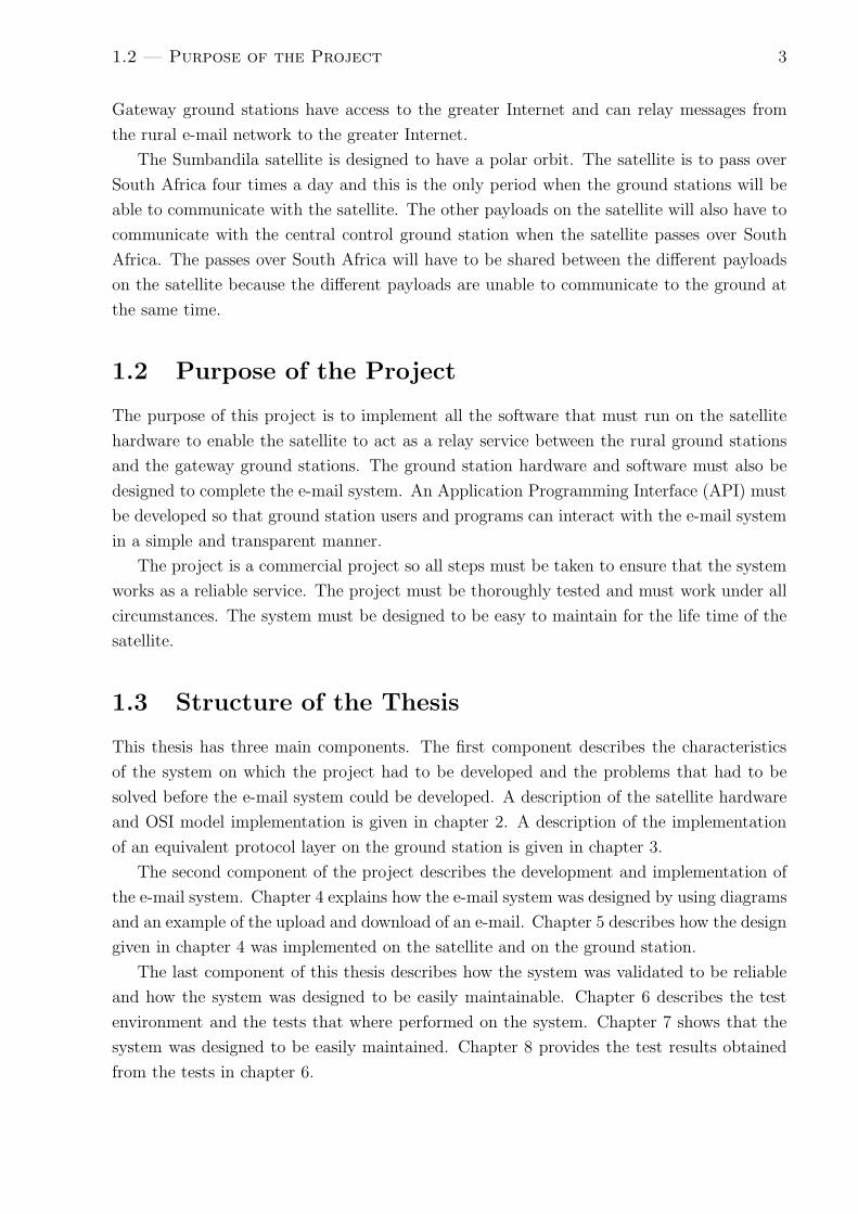
1.2 Purpose of the Project
The purpose of this project is to implement all the software that must run on the satellite
hardware to enable the satellite to act as a relay service between the rural ground stations
and the gateway ground stations. The ground station hardware and software must also be
designed to complete the e-mail system. An Application Programming Interface (API) must
be developed so that ground station users and programs can interact with the e-mail system
in a simple and transparent manner.
The project is a commercial project so all steps must be taken to ensure that the system
works as a reliable service. The project must be thoroughly tested and must work under all
circumstances. The system must be designed to be easy to maintain for the life time of the
satellite.
1.3 Structure of the Thesis
This thesis has three main components. The first component describes the characteristics
of the system on which the project had to be developed and the problems that had to be
solved before the e-mail system could be developed. A description of the satellite hardware
and OSI model implementation is given in chapter 2. A description of the implementation
of an equivalent protocol layer on the ground station is given in chapter 3.
The second component of the project describes the development and implementation of
the e-mail system. Chapter 4 explains how the e-mail system was designed by using diagrams
and an example of the upload and download of an e-mail. Chapter 5 describes how the design
given in chapter 4 was implemented on the satellite and on the ground station.
The last component of this thesis describes how the system was validated to be reliable
and how the system was designed to be easily maintainable. Chapter 6 describes the test
environment and the tests that where performed on the system. Chapter 7 shows that the
system was designed to be easily maintained. Chapter 8 provides the test results obtained
from the tests in chapter 6.

1.3 — Structure of the Thesis 4
The conclusion gives a critical analysis of the project’s final implementation and suggests
steps that can be taken to improve the system.

Chapter 2
OSI Layer Constraints
A description of the open systems interconnect (OSI) layer model will be given in this
chapter. The structure of the OSI layer that the e-mail system was designed on was largely
determined by the hardware and software that SunSpace supplied for the project. This
chapter will describe the structure of the OSI layer so that the decisions made in the next
chapters can be better understood.
2.1 OSI Model
ApplicationApplication
PresentationPresentation
SessionSession
TransportTransport
NetworkNetwork
Data-LinkData-Link
PhysicalPhysical
Figure 2.1: OSI model of the network architecture.
The International Organisation for Standardization (ISO) developed the 7 layer Open Sys-
tems Interconnect (OSI) model to provide a standard way to partition the network function-
ality of a communications system [18]. Figure 2.1 shows a graphical representation of the
OSI model.
A description of the different layers will now be given:
5

2.2 — Physical Layer 6
• Physical Layer
The transmission of raw bits are described in this layer. The modulation scheme used
to transmit the data over a channel falls within this layer.
• Data-Link Layer
The raw bits transmitted in the physical layer must be understood by higher layers in
the model. The data-link layer provides a method to transfer frames of data over the
physical layer by providing error-detection, correction and framing of data packets.
• Network Layer
The network layer provides routing between nodes in a packet switched network [18].
A network layer data unit is called a packet while a data-link layer data unit is called
a frame.
• Transport Layer
The transport layer provides a transparent transfer of data between end-users on the
end hosts. The transport layer data unit is typically called a message. The transport
layer typically does not run on intermediate switches and routers.
• Application Layer
The rest of the three layers are all going to be viewed as the Application layer for
the purpose of this discussion. Protocols that are used to send files between users on
end-hosts run on this layer for example.
2.2 Physical Layer
The VHF UHF Communication Unit (VUCU) that SunSpace manufactures was used as the
radio on the satellite for the Communications payload. The VUCU design was influenced by
the radio system used in the original Stellenbosch University Satellite (SUNSAT) that the
University of Stellenbosch launched on the 23 February 1999.
SUNSAT was an Orbital Satellite Carrying Amateur Radio (OSCAR) [12], which is a
satellite that uses amateur radio frequencies to communicate with the earth. The amateur
frequencies that were used on SUNSAT were in the UHF and VHF bands. The VUCU was
also developed to work in these bands.
As the e-mail system is a commercial project, the standard amateur radio frequencies
could not be used for this project. The Independent Communications Authority of South
Africa (ICASA) is responsible for managing the assignment of frequencies to bandwidth
users in South Africa. The communications payload had to apply to this authority for the
up-link frequencies. The International Telecommunications Union (ITU) is responsible for
the assignment of frequencies internationally and the frequency for the down-link had to be
applied for through this authority.

2.2 — Physical Layer 7
ICASA and the ITU assigned a separate frequency in the UHF band for the up-link and
the down-link. The frequencies that have been assigned are found approximately 0.2 MHz
apart. The VUCU does not have adequate hardware capabilities to demodulate the received
signal when the VUCU is transmitting because the transmitted signal power is significantly
higher than the received signal. Thus the VUCU cannot use full-duplex communication on
the channel causing the channel to be used in half-duplex mode.
A further restriction caused by the VUCU is that it was designed to implement full-
duplex communication. It is not able to do carrier sensing on the channel and the physical
layer protocol used in the VUCU modem does not use collision avoidance.
This has severe restrictions for our application because it means that the VUCU is not
able to implement half-duplex communication with any arbitrary higher level protocol. The
half-duplex communication must be controlled by the higher level protocol. This problem
will be explained in more detail in section 2.4 and the solutions to this problem used in the
e-mail system will be discussed in section 3.2 and 3.3.
2.2.1 The VUCU Modem
The VUCU has several different modems implemented on it and the one that is used for the
e-mail system is a 9600 baud G3RUH modem. The G3RUH modem is a popular amateur
radio modem first described by James Miller [16]. The G3RUH modem is used for the e-mail
system because this is the modem that SunSpace runs its higher level protocols over.
The G3RUH Modem uses the High-Level Data Link Control (HDLC) protocol as the
data-link layer protocol which will be described in section 2.3.
The implementation of the modem on the satellite and the ground station did not form
part of the development of the e-mail system. A brief description of the G3RUH modem is
given here to allow the user to have a better understanding of the complete system and a
detailed description of the modem can be found in [16].
Transmit:
1. Bits from the data-link layer are sent serially to the modem.
2. Data is then sent through a scrambler (or randomizer) to remove any DC offset. A
DC offset can be caused by a long sequence of equal binary data bits being sent to the
modem. The scrambler also flattens the spectrum of the modulated signal which helps
keep the modulated signal within the specified bandwidth.
3. The scrambler uses a linear feedback shift register (LFSR) to scramble the data.
4. For each bit in the scrambled data a Nyquist pulse [16] is generated. This is achieved
by filtering the scrambled data with a finite impulse response (FIR) filter to produce
the Nyquist pulse for each bit.

2.3 — Data-Link Layer 8
5. The goal of the filter is to decrease the bandwidth used by the signal and the inter-
symbol interference between the modulated symbols.
6. The signal generated from the filter is then applied to a voltage control oscillator (VCO)
to produce a ±3 kHz deviation Frequency Modulated(FM) signal at an intermediate
frequency (IF).
7. The IF signal is then mixed up to the correct radio frequency(RF) and transmitted
over the channel.
Receive:
1. The received RF signal is mixed down to the AF signal.
2. The AF signal is then sampled at the correct time to obtain the data bits.
3. This can be achieved by correlating the signal with the matched(time reversed) FIR
filter used in the transmit procedure and sampling at the peaks that are obtained from
this process [19].
4. The bits are then unscrambled using the same LFSR as in the transmit procedure.
5. The unscrambled bits are then sent up to the data-link layer.
The basic operation of the G3RUH filter has been outlined; the HDLC protocol and
Data-Link protocol used by SunSpace will now be described.
2.3 Data-Link Layer
The VUCU uses a subset of the Higher-Level Data Link Control protocol to transmit bits
over the link. HDLC is a bit orientated protocol that can work over synchronous and
asynchronous links [23]. The structure of a HDLC frame is shown in figure 2.2.
01111110 Data bytes (Bit stuffed) CRC 01111110
Figure 2.2: Structure of a Higher-Level Data Link Control (HDLC) frame.
The protocol uses the unique sequence ‘01111110’ (7E in hexadecimal notation) to frame
a packet. Bit stuffing is applied to the data within the packet. Bit stuffing adds a ‘0’ to a
sequence of six ones before the sixth one to ensure that the start/stop HDLC sequence does
not occur within a data frame. This ensures that a sequence of five ones is followed by a

2.4 — Transport and Network Layer 9
zero. This makes it impossible for a start or stop sequence to be found in the packet unless
a bit error is introduced into the packet.
The sequence at the beginning of the frame is also necessary for the receiving modem to
synchronise its clock with the transmitter by using a digital phase lock loop.
A Cyclic Redundancy Code (CRC) is used to distinguish a valid packet from packets
where bit errors have been introduced. A CRC adds redundant information to a packet to
enable the detection of errors in the packet if they occur. A full description of the functioning
of a CRC can be found in [18].
The CRC used in the standard HDLC is described by the CRC-16 polynomial x16 +x
15 +
x2 + 1. The reciprocal polynomial of the CRC-16 polynomial is used to generate the CRC
used in the SunSpace implementation of HDLC. The reciprocal polynomial is calculated by
replacing the x16 though x
0 coefficients in the original polynomial with the x0 through x
16
coefficients. The only difference that this causes is that the reciprocal polynomial generated
CRC is in bit-reversed order to the original CRC. The CRC calculation used in the SunSpace
implementation of HDLC starts with an initial value of the CRC set to FFFF in hexadecimal
notation.
SunSpace only uses the framing technique of HDLC and uses a custom protocol to de-
scribe the contents of the frames. The layout of the frame is shown in figure 2.3.
Frame Type Frame Length Data bytes
Figure 2.3: Structure of the SunSpace custom protocol frame in a HDLC frame.
The frame structure that SunSpace uses within the HDLC frame is very simple. There
are two types of frames: tunneled network traffic and tunneled Controller Area Network
(CAN) bus traffic. The transfer of bytes from one VUCU to another VUCU is now known
and the protocol that runs on top of the data-link layer is discussed in the next section.
2.4 Transport and Network Layer
The block diagram of the layout of the satellite architecture is shown in figure 2.4. The
on-board computer (OBC) that the e-mail system uses on the satellite is also supplied by
SunSpace. The OBC has the following components:
• An SH4 processor as its main microprocessor. The SH4 is a 32-bit reduced instruction
set computer (RISC) microprocessor produced by the chip manufacturer Renasis.
• 8 Mb of error correction code (ECC) protected synchronous dynamic random access
memory (SRAM). The SRAM provides some protection from radiation-induced upsets
in the space environment.

2.4 — Transport and Network Layer 10
CAN Bus
VUCU
OBC
Figure 2.4: Satellite block diagram of the system layout.
• Two Cygnal 8051 processors with integrated controller area network (CAN) controllers
to connect to the CAN bus.
• Two 8 Mb banks of NOR flash memory where the operating system images and backup
file system images are stored.
• Two 256 MB banks of NAND Flash memory where the normal file system is stored.
SunSpace uses the real-time operating system QNX for the OBC, which is able to run on
the SH4 processor. QNX is a fully Portable Operating System Interface(POSIX) compliant
operating system. POSIX is a standard that is based on the UNIX operating system that
was created to enable a standard way for software to interface with the operating system.
POSIX was designed to make it possible to write software that can run on different types of
operating systems without having to change the original software.
It was decided to use QNX as the operating system for the e-mail system because the
project then has access to the same software environment that SunSpace uses. A few reasons
for this decision is now discussed. By using QNX, the e-mail system is able to access many
of SunSpace’s systems. For example it will be possible to update software on the satellite
by using the main Telemetry, Tracking and Control communication path if for some reason
the e-mail system’s communication path fails. This can be done using existing software
that SunSpace has written without having to create any new custom software. SunSpace
implemented a protocol that runs on the CAN bus. It enables the transmission of telemetry
commands and tunneling of network data on the CAN bus.
Access to the CAN Bus is transparent to software running on the QNX operating system
because SunSpace has implemented a network driver for QNX. The network driver makes the
CAN bus appear as a normal Ethernet hardware device to the QNX network stack. Software
running on the SH4 processor is thus able to run a standard network stack. This makes it
possible to use the User Datagram Protocol (UDP) or the Transmission Control Protocol

2.5 — Application Layer 11
(TCP) as the transport layer protocol and the Internet Protocol (IP) as the network layer
protocol.
This creates a transparent transport layer between the OBC and a ground station as
long as the ground station also implements the complete network stack as outlined in this
chapter. Normal IP traffic is thus able to run over the channel. The e-mail system can then
be completely implemented in the application layer.
2.5 Application Layer
The use of the QNX environment also has some added benefits in the application layer.
SunSpace created a process monitor program that runs on QNX on the SH4. The process
monitor is a program designed to manage user defined programs. The process monitor
makes it possible to start and stop a managed program on the OBC using telecommands
and also ensures that when a program is started it executes continuously. The program that
is developed to implement the e-mail system can be added to the managed programs. The
interface to the e-mail system will then be similar to any other payload found on the rest of
the satellite.
The e-mail system program runs on a fully functional operating system with a complete
network stack. The software can thus be designed as you would design any other software
that runs on Linux. The design must only take the following considerations into account:
• The OBC is an embedded environment so there are restrictions on the processing power
of the SH4 and the amount of memory available to the application.
• The link is half-duplex and the VUCU is unable to enforce half-duplex operations at
the physical layer.
The implication of the second point is that it is impossible to run TCP over the com-
munications channel, which restricts the use of standard higher level protocols such as the
File Transfer Protocol (FTP). TCP requires a full-duplex link or a half-duplex link that has
hardware that has collision avoidance capabilities to ensure that the link is accessed in a
half-duplex manner. The VUCU is not able to do this so UDP must be used as the Trans-
port Layer protocol. The application that uses UDP must then ensure that the channel is
accessed in a half-duplex manner.
The OSI layer upon which the e-mail system must be developed on the satellite has
now been described. The next chapter will show how an equivalent OSI layer structure was
implemented on the ground station hardware. The choice of application layer protocols for
the transferring of e-mails will also be described in the next chapter.

Chapter 3
OSI Layer System Design
The e-mail system forms part of the application layer. The design of the e-mail system can
be described only after the solutions to the various problems found in the lower layers of the
OSI model are given.
The ground stations must be designed to be cost effective because more than one of
them are going to be manufactured and distributed across South Africa. Desktop computer
hardware is relatively inexpensive and have more than enough resources available for the
project to function correctly.
The Linux operating system is copyrighted using the general public license (GPL). This
makes it possible to use the operating system freely and gain access to the source code of
the operating system because of the way the GPL license is designed [4]. Thus by using the
Linux operating system the costs of the ground station as a whole can be reduced because
no operating system licenses have to be purchased. Being able to access the source code of
the Linux operating system also enables the developer to tailor the operating system to the
e-mail system’s needs.
To design the e-mail system, a functional ground station had to be developed. It was de-
cided to use a conventional desktop computer and the Linux operating system to develop the
ground stations for the reasons described above. Specifically the Ubuntu Linux distribution
was used as the operating system on which to develop the software. Ubuntu is similar to
Debian and uses the same program packaging techniques as Debian. Debian runs on many
different hardware architectures by default [3]. Thus changing the distribution from Ubuntu
to Debian should be possible if different hardware to the desktop computer is chosen for the
final ground station hardware.
The design of the OSI layer used on the ground station hardware is described in this
chapter.
3.1 Physical and Data-Link Layer
If more of the OSI layers are implemented in software on the ground station desktop computer
the less the final ground station hardware will cost. The reason for this is that less specialised
12

3.1 — Physical and Data-Link Layer 13
hardware will have to be designed or purchased to implement the OSI layer components.
Thus it was decided to try implement as much as possible of the OSI layers in software or
by using standard desktop hardware components.
Specialised hardware must be used to convert the RF signal down to an AF signal. The
conversion is performed by a transmitter or a receiver. The AF signal must be interpreted in
the physical layer and a modem performs this function. It is not possible to implement the
conversion from RF signal to AF signal without using some kind of specialised hardware.
Thus the conversion from RF signal to AF signal could not be implemented in software on
the desktop computer. More details on the hardware setup is given in chapter 6.
Once the AF signal is obtained from the RF signal using the specialised hardware, a
G3RUH modem must demodulate the signal to generate packets to be passed up to the
ground station’s transport and network layer. A G3RUH modem must also be used to
generate the outgoing AF signal from packets received from the ground stations transport
and network layer.
The open source software modem called soundmodem written by Thomas Sailor was used
to implement the modem used on the ground stations [20]. soundmodem uses a standard
desktop computer’s sound card to capture and generate the AF signal. The software performs
all the functionality of a G3RUH modem in software.
soundmodem is written to work as a Terminal Node Controller (TNC) on an AX.25
network. AX.25 is a physical and data-link layer protocol that is used on Amateur Packet
Radio Networks (APRN) [8, 1].
The AX.25 standard uses HDLC to frame the AX.25 packets. This is useful because
the VUCU also uses HDLC to frame the SunSpace data-link layer protocol (see section
2.3). AX.25 uses a different CRC polynomial to generate the checksum that is added to the
HDLC frame, as seen in figure 2.2. Thus soundmodem had to be modified to use the correct
checksum that SunSpace uses for its own HDLC implementation.
Because the AX.25 standard is a data-link layer standard, there are many features that are
not suitable for this project. Thus the soundmodem software had to be modified to remove
the AX.25 data-link layer parsing of the packets within an HDLC frame. The SunSpace
data-link layer packet parsing was then added to soundmodem so that it could communicate
properly with the VUCU.
soundmodem also used a sampling frequency of 14400 Hz to sample the received audio at
the sound card and to generate the audio for transmission. At this sampling frequency bit
errors occurred during transmission and packets where dropped.
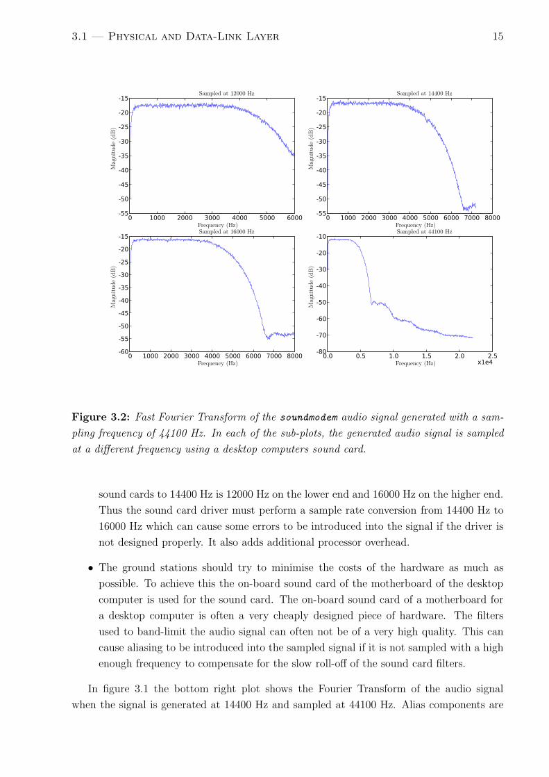
Figure 3.1 and figure 3.2 shows the Fast Fourier Transform of the soundmodem generated
AF signal recorded by a desktop computer using its sound card. soundmodem generates the
audio signal at 14400 Hz and 44100 Hz respectively. The soundmodem generated AF signal
is sampled at different frequencies in the sub-plots of the figures to observe the affect that
the sampling frequency has on the received audio signal.
Looking at the figures 3.1 and 3.2, it can be deduced that the bandwidth of the signal is

3.1 — Physical and Data-Link Layer 14
0 1000 2000 3000 4000 5000 6000-50
-45
-40
-35
-30
-25
-20
-15
0 1000 2000 3000 4000 5000 6000 7000 8000-60
-55
-50
-45
-40
-35
-30
-25
-20
-15
0 1000 2000 3000 4000 5000 6000 7000 8000-60
-55
-50
-45
-40
-35
-30
-25
-20
-15
0.0 0.5 1.0 1.5 2.0 2.5x1e4
-80
-70
-60
-50
-40
-30
-20
-10
Sampled at 12000 Hz
Frequency (Hz)
Mag
nit
ude
(dB
)
Sampled at 14400 Hz
Frequency (Hz)
Mag
nit
ude
(dB
)
Sampled at 16000 Hz
Frequency (Hz)
Mag
nit
ude
(dB
)
Sampled at 44100 Hz
Frequency (Hz)
Mag
nit
ude
(dB
)
Figure 3.1: Fast Fourier Transform of the soundmodem audio signal generated with a sam-
pling frequency of 14400 Hz. In each of the sub-plots, the generated audio signal is sampled
at a different frequency using a desktop computers sound card.
approximately 4200 Hz because the signal drops by about 3 dB at this frequency compared
to the signal strength at the lower frequencies. According to Nyquists theorem [28], an exact
replication of the audio signal can be reconstructed if the audio signal is band-limited and
sampled at more than twice the bandwidth of the audio signal. Thus the signal should be
sampled at a minimum of approximately 8400 Hz. The signal should be sampled at a higher
frequency than this to compensate for the roll-off of the filter used to band-limit the signal.
Thus by adding a 50% margin of error the signal should be sampled at approximately 12600
Hz.
In theory the sampling frequency of 14400 Hz used by soundmodem should work. In
practice the sampling frequency did not work and there are several reasons for this:
• Most sound cards have a finite set of sampling frequencies at which they are able
to sample. The utility pa devs provided by the advanced linux sound architecture
(ALSA) can be used to determine the set of sampling frequencies. For most sound
cards 14400 Hz is not one of these frequencies. The closest frequencies found on most
3.1 — Physical and Data-Link Layer 15
0 1000 2000 3000 4000 5000 6000-55
-50
-45
-40
-35
-30
-25
-20
-15
0 1000 2000 3000 4000 5000 6000 7000 8000-55
-50
-45
-40
-35
-30
-25
-20
-15
0 1000 2000 3000 4000 5000 6000 7000 8000-60
-55
-50
-45
-40
-35
-30
-25
-20
-15
0.0 0.5 1.0 1.5 2.0 2.5x1e4
-80
-70
-60
-50
-40
-30
-20
-10
Sampled at 12000 Hz
Frequency (Hz)
Mag
nit
ude
(dB
)
Sampled at 14400 Hz
Frequency (Hz)
Mag
nit
ude
(dB
)
Sampled at 16000 Hz
Frequency (Hz)
Mag
nit
ude
(dB
)
Sampled at 44100 Hz
Frequency (Hz)
Mag
nit
ude
(dB
)
Figure 3.2: Fast Fourier Transform of the soundmodem audio signal generated with a sam-
pling frequency of 44100 Hz. In each of the sub-plots, the generated audio signal is sampled
at a different frequency using a desktop computers sound card.
sound cards to 14400 Hz is 12000 Hz on the lower end and 16000 Hz on the higher end.
Thus the sound card driver must perform a sample rate conversion from 14400 Hz to
16000 Hz which can cause some errors to be introduced into the signal if the driver is
not designed properly. It also adds additional processor overhead.
• The ground stations should try to minimise the costs of the hardware as much as
possible. To achieve this the on-board sound card of the motherboard of the desktop
computer is used for the sound card. The on-board sound card of a motherboard for
a desktop computer is often a very cheaply designed piece of hardware. The filters
used to band-limit the audio signal can often not be of a very high quality. This can
cause aliasing to be introduced into the sampled signal if it is not sampled with a high
enough frequency to compensate for the slow roll-off of the sound card filters.
In figure 3.1 the bottom right plot shows the Fourier Transform of the audio signal
when the signal is generated at 14400 Hz and sampled at 44100 Hz. Alias components are

3.1 — Physical and Data-Link Layer 16
introduced into the signal at 9600 Hz and 19200 Hz which should have been filtered out of
the signal by the sound card filter. When the sampling rate for reception is also at 14400
Hz these aliased components are introduced into the desired signal causing bit errors. The
aliasing is not noticed in the top right plot in figure 3.1 because the aliasing is of a lower
magnitude than the desired signal. This might be good enough for analogue audio but is not
good enough for data communication. These harmonics are not nearly as prominent when
the signal is generated with a 44100 Hz sampling rate as seen in figure 3.2.
Table 3.1: Bit error rate when different sampling frequencies are used in soundmodem. The
BER is determined when 1 × 106 bits were transmitted.
Sampling Rate (Hz) Bit Error Rate (×10−6)
12000 7102
14400 352
16000 112
22050 0
44100 0
Sound cards can vary dramatically in quality and when choosing a sound card for the
ground station a method must be used to determine the bit errors that occur at different
sampling frequencies to enable the choice of the optimum frequency to sample at. Table 3.1
shows the bit error rates that are observed when two desktop computers are connected to
each other using soundmodem. A few of the default sampling rates at which sound cards are
able to sample are used for the table. The application soundmodemconfig provided by the
soundmodem software package can be used to predict the bit error rate. The table shows that
at 14400 Hz the bit error rate is 352 × 10−6 between the computers over a good audio link.
This is unacceptable because virtually no errors should occur over this link.
At 22050 Hz perfect communication is observed. So for the specific setup used for the e-
mail system’s purposes, 22050 Hz should be an adequate sampling rate used in soundmodem.
This does not take into account the differences that could be observed between a VUCU
generated audio signal and a soundmodem generated signal, which could cause the bit error
rate to be higher.
Figure 3.3 shows the Fast Fourier Transform of the VUCU audio signal. The signal
appears to have approximately the same bandwidth as the soundmodem generated signal but
has an extra DC component that is a known characteristic found on the VUCU hardware.
This DC component is filtered out by the soundmodem software.
soundmodem was initially not able to communicate with the VUCU but through the
changes outlined in this section it was developed into a viable modem to be used on the
ground station hardware.

3.2 — Transport and Network Layer 17
0.0 0.5 1.0 1.5 2.0 2.5-80
-70
-60
-50
-40
-30
-20
-10
Frequency (kHz)
Mag
nit
ude
(dB
)
Figure 3.3: Fast Fourier Transform of the VUCU audio signal sampled at 44100 Hz.
3.2 Transport and Network Layer
Now that the physical and data-link layer problems have been solved by using soundmodem,
the packets generated by soundmodem must be passed to the Linux network stack and the
packets generated by the Linux network stack must be passed to soundmodem.
As described earlier, soundmodem was developed to be used as part of the AX.25 protocol.
The Keep It Simple, Stupid (KISS) protocol that AX.25 uses to connect an AX.25 TNC to
a computers network stack is almost the same as the Serial Line Internet Protocol (SLIP)
used to connect any arbitrary serial network device to a computers network stack. The only
difference is that KISS has TNC control and other functions built into the protocol. These
are not necessary for the SunSpace data-link layer protocol.
soundmodem uses a pseudo terminal, which is an emulated terminal in Linux, to make
the modem appear as a normal serial AX.25 TNC to the Linux network stack.
SLIP is normally used to connect to a serial port modem and works over a point-to-point
link. SLIP and KISS simply frame the packets that are placed into the pseudo terminal
with a unique character at the beginning and end of the packet and then escapes any of
3.3 — Application Layer 18
these characters that are found within the packet. This is a similar process that the HDLC
protocol uses in section 2.3. The Linux network stack can then use the framing protocol
used by SLIP and KISS to retrieve the packets from the pseudo terminal. Thus by removing
all the TNC control from soundmodem, soundmodem can be made to look like a normal SLIP
modem because SLIP uses the same framing protocol as KISS.
The Linux utility slipattach is used to connect the pseudo terminal to the Linux network
stack. soundmodem is then viewed as a normal network device and all of the Linux network
utilities are available to this device.
Thus the transport layer, namely UDP, is functional on the ground station.
3.3 Application Layer
In section 2.5 it was shown that the application layer protocol should use UDP to com-
municate and should not have unnecessary overhead to reduce the load on the OBC. The
protocols should also access the link in a half duplex manner. Two protocols, namely the
Network File System (NFS) and Trivial File Transfer Protocol (TFTP) were isolated as
potential candidates for these protocols.
3.3.1 NFS
NFS is a widely used distributed file system that was originally developed by Sun Microsys-
tems, Inc. QNX has a NFS client and server available for use on the system. The NFS client
can only use NFS protocols 2 and 3. Several properties of the NFS protocol version 3 is now
discussed:
• NFS has two components, namely a client and a server.
• NFS is able to run over UDP and works in a lock-step protocol. Because the system
uses a lock-step protocol, only one packet is transmitted over the link at one time.
This is perfect for the half-duplex link used for this project.
• NFS uses Sun’s remote procedure call library to implement the protocol.
• NFS allows the distributed file system to be viewed like a normal part of the file system
to the client machine. Thus files can be copied, moved, renamed and listed like any
other file in the file system. This makes it trivial to implement the e-mail system
because files can be simply moved from remote directories to local directories or vice
versa.
• NFS requires the distributed file system to be mounted and unmounted.
• There is authentication when a client mounts the NFS file system and during all
transfers of files using a variety of different authentication techniques [9].

3.3 — Application Layer 19
Testing the NFS protocol over the audio link using the QNX NFS client showed that
it worked successfully. The overhead involved using NFS is quite severe when compared to
TFTP and these results will be shown in section 8.2.
3.3.2 TFTP
TFTP is a very simple file transfer protocol that is often used for devices like routers to boot
off the network. A few properties of the protocol is now described:
• It uses a lock-step protocol to transfer files from a client to a server or vice versa.
• There is no connection setup or termination. The client simply requests to read a
file or write to a file and the transfer begins immediately. Thus there is virtually no
overhead involved before transferring a file.
• There is no host authentication or security used to protect the system from malicious
users. Thus this authentication must be implemented by the e-mail system.
• TFTP is unable to list the contents of a directory. This means that lists of files to
upload and download need to be created so that the e-mail system knows which files
to transmit.
• The file is broken up into 512 byte blocks and transferred in a lock-step protocol. This
creates a problem because the utilization of the satellite link cannot be optimised if
the packet size cannot be changed.
Request For Comments (RFC) 1350 [21] provided by the Internet Engineering Task Force
(IETF) provides a detailed specification of the protocol.
QNX has a TFTP client and server as a default part of the system. This implements
the basic RFC 1350. The QNX TFTP client is closed source but it seems to use a blocking
socket call when trying to read or write to a UDP socket. A socket is a method to access the
network stack described in the socket application program interface (API) which is described
in [18, 22]. Thus the client can block on a socket call when waiting for data to be read from
the socket for example. This causes the link to be used inefficiently if the bit error rate is
bad because data might not arrive at the socket to be read by the client. The client will
then never be able to carry on with any other processing. An alternative client was required
to fix this problem.
RFC 2347 [14], 2348 [13] and 2349 [15] propose the following modifications to the protocol
that are very useful for the e-mail system:
• RFC 2347 defines a method whereby protocol parameters can be passed between a
server and clients in a backwards compatible manner.

3.3 — Application Layer 20
• RFC 2348 defines an option whereby the blocksize used in the lock-step protocol can
be negotiated between the client and the server. This is very useful for our application
because the utilization of the satellite link can be optimised by selecting a packet size
that achieves the largest packet throughput for the link by adjusting the size of the
packet for the bit error rate that is observed on the channel.
• RFC 2349 defines options whereby the timeouts used on the client and server during
file transfer can be set. This is essential to optimise the usage of the satellite link
because it provides a deterministic method of controlling how long a ground station
will try to use the link (when the link fails) before the client keeps quiet.
The Linux ATFTP package contains a client and server which implement the extensions
just described. ATFTP also uses blocking socket calls to access the network stack, but it uses
a method whereby the socket is only read from if something has arrived from the network
stack. It uses the “select” POSIX system call to achieve this. Thus the system does not
block and the timeouts that it uses are much more reliable than the default TFTP client
used on QNX.
The ATFTP package had to be ported to the QNX operating system. The ATFTP
package seems to be well designed and cross-compiling the package was straightforward. The
following problems where fixed to make ATFTP work properly on QNX and are common
problems found when cross-compiling to QNX:
• In Linux the threading library libpthread is not part of the standard C library while
in QNX it is part of the standard library. Thus the libraries specified to the compiler
had to be changed to make the package link successfully.
• The QNX operating system does not have the sys\types.h C header file. So an
equivalent header file for QNX was created.
• The OBC uses a reduced functionality TCP/IP stack on QNX. Some of the socket
API functions are not implemented or not fully functional. These differences where
found and fixed for the QNX port of ATFTP.
• QNX does not have the getopt long function used to parse arguments that are passed
to an application as standard.
The functionality to set the number of timeouts before the file transfer is aborted was
fixed in the code in the original ATFTP client. A command line option was added to set
this value in the QNX port.
The TFTP and NFS clients are both good candidates for the application layer protocol
used to transfer files between the satellite and ground stations. NFS has the advantage that
a simpler design could be created because the contents of directories can be seen and files
are copied more easily.
3.3 — Application Layer 21
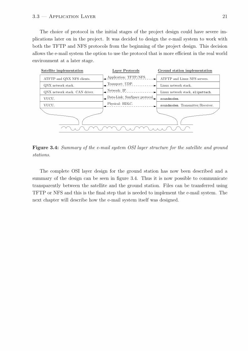
The choice of protocol in the initial stages of the project design could have severe im-
plications later on in the project. It was decided to design the e-mail system to work with
both the TFTP and NFS protocols from the beginning of the project design. This decision
allows the e-mail system the option to use the protocol that is more efficient in the real world
environment at a later stage.
Satellite implementation Ground station implementationLayer Protocols
ATFTP and QNX NFS clients.
QNX network stack.
QNX network stack. CAN driver.
VUCU.
VUCU.
ATFTP and Linux NFS servers.
Linux network stack.
Linux network stack, slipattach.
soundmodem.
soundmodem. Transmitter/Receiver.
Application: TFTP/NFS.
Transport: UDP.
Network: IP.
Data-Link: SunSpace protocol.
Physical: HDLC.
Figure 3.4: Summary of the e-mail system OSI layer structure for the satellite and ground
stations.
The complete OSI layer design for the ground station has now been described and a
summary of the design can be seen in figure 3.4. Thus it is now possible to communicate
transparently between the satellite and the ground station. Files can be transferred using
TFTP or NFS and this is the final step that is needed to implement the e-mail system. The
next chapter will describe how the e-mail system itself was designed.

Chapter 4
E-mail System Design
In this chapter the design of the e-mail system will be described. The first part of the chapter
will just give a few definitions of administration directories and files that are used in the
e-mail system to enable an easier understanding of the system when the design is shown in
section 4.3. The term upload will be used to describe when a file gets transferred from a
ground station to the satellite. The term download will be used to describe when a file gets
transferred from the satellite to the ground station.
4.1 Components of the System
4.1.1 Ground Station
The e-mail domain is used to identify ground stations in the system. Table 4.1 shows the
definition of the domain structure used in this text.
Table 4.1: Domain and sub-domain definition. stb.sumbandilasat.co.za is used as an exam-
ple to explain the definitions.
Complete domain
Sub-domain Domain
stb sumbandilast.co.za
Each ground station has a specific sub-domain which is a unique key to describe the
ground station. For example the complete domains cpt.sumbandilast.co.za, blm.sumbandi-
last.co.za and jhb.sumbandilast.co.za may be used to describe the ground stations found at
Cape Town, Bloemfontein and Johannesburg respectively.
The ground station can have many users, for example [email protected] and
[email protected]. Each ground station also has a unique IP address for the
satellite ground station network. The ground station has the following directories to keep
track of all the e-mails:
22

4.1 — Components of the System 23
• Outbox
This is the outbox where all e-mails to non-local users are placed before they are
uploaded to the satellite.
• Inbox
This is where all e-mails downloaded from the satellite are placed before they are moved
by the ground station software to the correct user inboxes.
• User Inboxes
The e-mails for a specific user received from the satellite or another local user are
placed in this directory.
• Default User Inbox
This is where all e-mails received at a ground station with the correct domain name and
incorrect user name are placed. For example if an e-mail is sent to [email protected]
lasat.co.za and the user does not exist on the ground station ‘cpt’ then the e-mail will
be placed in this inbox.
4.1.2 Satellite
The satellite does not keep track of specific users on a ground station. The satellite has the
following directory structure to administer the e-mails and ground stations that exist on the
e-mail system network:
• Global Outbox
This is the global outbox for e-mails that have been uploaded to the satellite but are
not being sent to a user on the e-mail system network. These types of e-mails are e-
mails that are not destined for the sumbandilasat.co.ca domain for the example being
used in this chapter.
• Ground Station Outbox
This is the outbox where all e-mails for a specific ground station are placed once they
have been uploaded to the satellite and are ready to be downloaded to the ground
station. E-mails are downloaded from here to the Inbox on the ground station. This
directory is simply named after the complete domain of the ground station.
• Inbox
The global inbox where e-mails are placed once they have been uploaded from a ground
station to the satellite and before they are moved to the correct Ground Station
Outbox.
• Administration
The directory where all administration files described in the next section are stored.

4.2 — Design Choices 24
4.1.3 Administration Files
The system is designed to work on TFTP. TFTP is unable to list the contents of remote direc-
tories. Thus file lists are needed to keep track of files that must be uploaded or downloaded.
The different files used for these lists are now described and the files used to acknowledge
uploads and downloads are also described.
• Upload List
This file is maintained by the ground station. It contains the list of all the files that
must be uploaded to the satellite. Files are removed from this list once the satellite
has uploaded the file and acknowledged that the file has been uploaded.
• Upload Ack List
This is a file that the satellite maintains to record which files have been uploaded
already. The file is used to make sure that the satellite does not upload a file twice.
• Upload File Ack
This is sent from the satellite to the ground station to let the ground station know
that a file has been uploaded. An Upload File Ack is sent to the ground station to
acknowledge the reception of a file for each file individually.
• Download List
This is the file on the satellite that contains the list of all the files that must be
downloaded. Only the satellite is interested in this file and the ground station never
sees this file.
• Download Ack List
Once a file is downloaded to the ground station a ground station adds the file to this
list. It contains the list of all files that have been downloaded to the ground station.
The satellite uploads this file to see which files have been downloaded successfully.
• Download OK
The satellite sends this file to the ground station once it has uploaded the Download
Ack List to let the ground station know that the Download Ack List has been up-
loaded. This lets the ground station know that it can remove all the administration
files for the downloaded files.
4.2 Design Choices
The e-mail system was designed to be able to transfer any arbitrary file. The goal was to
make the satellite software to be as simple as possible. The satellite does not do any parsing
of e-mails. A simple file naming strategy is used to retrieve the destination address of a file.
There are two types of ground stations used for this system. Normal ground stations do
not have any access to the Internet other than communicating through the satellite network.

4.3 — Flow Charts of the Different Components 25
Gateway ground stations have access to the Internet and act as gateways between the satellite
network and the greater Internet.
The e-mail system is designed to be as reliable as possible. If the link fails unexpectedly
at any point in the transfer process or the software on the satellite is switched off by the
satellite control, the system must be able to recover from the event.
For every file that is uploaded or downloaded the file is only removed from the system
once the upload or download has been acknowledged as successful. Thus the upload or
download of a file is reliable.
E-mail clients and user applications can be used to ensure end-point to end-point delivery
of the message. The e-mail system only allows the ground station to be able to determine
when a file has been uploaded successfully.
The e-mail system was also designed to have a priority system. Each ground station has
a priority assigned to it and each e-mail has a priority assigned to it. The ground station
priority takes precedence. This can be used to ensure that gateway ground stations get more
service time which will probably be necessary because gateway ground stations will receive
more traffic than other ground stations.
The e-mail priority can be used to ensure that certain users have different priorities at
a ground station to make sure that the important users get serviced first for that ground
station.
Now that a background to the terminology used in this chapter has been given, a de-
scription of the e-mail system can be described in detail.
4.3 Flow Charts of the Different Components
4.3.1 Download
Figure 4.1 and figure 4.2 show the flow charts that describe how the downloading of files is
implemented on the satellite and ground station respectively. The flow chart in figure 4.1 is
executed when a ground station is selected to be serviced by the satellite. The flow chart in
figure 4.2 is executed regularly by a ground station.
In step 1 in figure 4.1 the Download List is created from the files in the specific ground
stations Outbox or Global Outbox. For a gateway ground station this will be created from
the files in the Global Outbox and for a normal ground station it will be created from the
files in the ground station’s specific Outbox.
Step 3 is only executed if there are new files to download. In step 3 three attempts
to retrieve the Download Ack List are executed to give the ground station a fair chance of
being serviced by the satellite if the link to the ground station is not particularly good. Thus
if a ground station is found in a region where physical attributes of the region produce a bad
link compared to other ground stations, the ground station is still serviced by the satellite.
If the Download Ack List is not retrieved successfully the satellite then exits the flow
chart and services the next ground station. If the Download Ack List is retrieved then step

4.3 — Flow Charts of the Different Components 26
1. Create Download
List, this is created
from all the files in the
ground station’s outbox
2. Are there
files to down-
load?
3. Retrieve Download
Ack List from the
ground station. There
are 3 attempts to obtain
this list.
4. Retrieved
file success-
fully?
5. Acknowledge that
the Download Ack
List was uploaded. A
Download OK file is sent
to the ground station
6. Delete all the files
listed in Download Ack
List because the files
have already been down-
loaded.
7. Download the rest
of the files in Download
List. Each file is down-
loaded only once.
NO
NO
YES
YES
EXIT
START
Figure 4.1: The satellite download flow chart. This flow chart is executed whenever a
ground station is being serviced by the satellite OBC.
5 is executed. The Download OK file is then transmitted to the ground station to let the
ground station know that the Download Ack List had been uploaded successfully.
Only one attempt is made to download the Download OK file. If this file is not downloaded
successfully it does not influence the rest of the flow chart significantly. If the ground station
receives the Download OK file then step 2 in figure 4.2 is executed. The reason why the
Download Ack List is deleted in step 2 in figure 4.2 once the Download OK file is received
is because then the ground station knows that the satellite has uploaded the Download Ack
List successfully. Thus the files in the list do not have to be acknowledged anymore.

4.3 — Flow Charts of the Different Components 27
1. Received
Download OK
file?
2. Delete the Download
OK file and empty the
Download Ack List
3. Are there
new files in
the inbox?
4. Add the new files
to the Download Ack
List.
5. Move new files to the
correct user inboxes.
NO
NO
YES
YES
EXIT
START
Figure 4.2: The ground station download flow chart. This flow chart is executed whenever
a file is received on a ground station by the ground station software.
If the Download OK was transmitted to the ground station by the satellite and the ground
station does not receive it then all that happens is the next time the satellite services the
ground station it will re-upload the Download Ack List with the old entries still present in
the list.
After step 6 in figure 4.1 the satellite then starts to download the files (step 7, figure 4.1).
When the ground station receives a new file in step 3 of figure 4.2 it simply adds this file to
the Download Ack List (step 4, figure 4.2) and then moves the file to the correct ground
station User Inbox or the Default User Inbox (step 5, figure 4.2). If the ground station
is a gateway ground station then the information will be forwarded to the greater Internet
if necessary.
The downloading of e-mails has now been described and a full transactional interface is
provided. Files are only deleted from the satellite once the ground station has acknowledged

4.3 — Flow Charts of the Different Components 28
that it has received the file, thus a reliable down-link is provided.
4.3.2 Upload
1. Received
an Upload
File Ack?
2. Remove acked file
from Upload List and
delete the file that was
acknowledged.
NO
YES
EXIT
START
Figure 4.3: The ground station upload flow chart.
Figure 4.3 shows the flow-chart that describes how the ground station software imple-
ments the uploading of files to the satellite. This file is executed regularly by the ground
station. It will be executed approximately once a second. If a ground station receives an
acknowledgement for a file from the satellite to confirm that the satellite has uploaded the
file successfully then the file is deleted on the ground station and the file is removed from
the Upload List.
The flow chart on the satellite shown in figure 4.4 is more complicated than the ground
station upload flow chart and will now be explained. The flow chart is executed when a
ground station is serviced by the satellite. In step 1 the satellite tries to retrieve the Upload
List from the ground station and it is repeated three times for the same reasons described
in section 4.3.1 in the download flow chart.
Once the Upload List has been received, the satellite needs to determine which e-mails
have already been uploaded to prevent duplicate uploading of e-mails. The file Upload Ack
List on the satellite is required to record this information because once a file has been
uploaded to the satellite it is moved to a different mailbox on the satellite. For this reason

4.4 — Typical File Transfer Sequences 29
it is impossible for the satellite to create the Upload Ack List from information on the
satellite.
The only problem that can occur if for some unknown reason the Upload Ack List is
removed on the satellite, is that the files that were in the list will potentially be uploaded
twice.
The Upload Ack List is created when a new Upload List is uploaded from the ground
station as shown in step 4. The new Upload List that was uploaded then has all the entries
in the Upload Ack List removed from it to make sure that a file is not uploaded twice (step
3).
If there are still files in the Upload Ack List, it means that the acknowledgements for
the files in the list where not received by the ground station. The ground station has thus
not removed the files from its Upload List. The acknowledgements for the files in the Upload
Ack List are then resent to the ground station (step 5, figure 4.4) so that the ground station
removes the entries from its Upload List (step 2, figure 4.3).
For all the files in the new Upload List calculated in step 3 of figure 4.4 the files are
uploaded. If the file is uploaded correctly then an Upload File Ack is sent to the ground
station to acknowledge the correct uploading of the file. This causes step 2 in figure 4.3 to
be executed.
If the file was not uploaded correctly then no other attempt is made to upload the file
in the current session. The file is simply deleted on the satellite (step 9, figure 4.4). Once
all the files have been attempted to be uploaded, the correctly uploaded files are moved to
the correct mailboxes on the satellite (step 11, figure 4.4). The flow chart then exits and the
next ground station is selected to be serviced.
The files that were not uploaded successfully will be uploaded the next time the ground
station gets serviced by the satellite. The file on the ground station is only deleted if the
satellite has acknowledged that the file has been uploaded to the satellite. Thus a reliable
uploading of files is guaranteed.
The uploading and downloading of e-mails has now been described. The next section
provides an example of the uploading of a file and downloading of a file to illustrate how the
system works in practice.
4.4 Typical File Transfer Sequences
An example of an upload and download of an e-mail is now shown to help explain how the
system works. Figure 4.5 shows the sequence of events that occur when an e-mail, called
E-mail 1, gets uploaded to the satellite. In this example a user at ground station Blm sends
E-mail 1 to User 2 at ground station Cpt.
The user is not on the local ground station thus it must be uploaded to the satellite. The
e-mail is placed in the Outbox and added to the Upload List. The actions in the dashed
block 1 in figure 4.5 illustrate how this is performed.

4.4 — Typical File Transfer Sequences 30
The ground station now has to be serviced by the satellite and the actions that occur
when this happens is shown in dashed block 2 in figure 4.5. The actions in dashed block
2 illustrates what happens in the flow-chart in figure 4.4. The e-mail is uploaded by the
satellite and the acknowledgement of this upload is sent back to the ground station.
When the satellite services ground station Blm the next time round it will upload the
Upload List and see that there are no new files to upload to the satellite because Blm has
removed E-mail 1 from the Upload List. E-mail 1 will be removed from the Upload Ack
List on the satellite.
The acknowledgement that E-mail 1 has been uploaded causes dashed block 3 in figure
4.5 to be executed. This dashed block illustrates what happens in the flow-chart in figure
4.3.
Now the e-mail has been uploaded from the ground station Blm. The satellite will then
have to download the file to Cpt when Cpt gets serviced next. Figure 4.6 illustrates what
happens when Cpt gets serviced.
Dashed block 1 in figure 4.6 performs the action in step 1 and the test in step 2 in figure
4.1. There are e-mails to download because E-mail 1 has been placed in Cpt’s outbox. Thus
the Download Ack List is retrieved from the ground station (step 3, figure 4.1). Dashed
block 2 in figure 4.6 performs the steps 4, 5 and 7 in figure 4.1. No files are deleted in step
6 in figure 4.1 because there where no other files on the satellite.
Cpt has thus received the E-mail 1 from the satellite and this causes the sequence of
events in dashed block 3 in figure 4.6 to be executed on the ground station. The steps 1, 2,
3, 4 and 5 in figure 4.2 are then executed because an e-mail was received and the Download
OK file was received. User 2 on ground station Cpt has now received an e-mail from ground
station Blm.
The next time Cpt gets serviced by the satellite dashed block 1 will again be performed
in figure 4.6. Dashed block 4 is then performed. The Download Ack List will be retrieved
from Cpt. The Download Ack List contains the E-mail 1 in the list so the new calculated
Download List on the satellite will no longer have the entry in it. Thus E-mail 1 is not
downloaded again and only the Download OK file is downloaded to the ground station. The
file on the satellite is then deleted (step 6, figure 4.1). Cpt receives the Download OK file and
the steps 1 and 2 are performed in figure 4.2 on the ground station.
The e-mail has now been cleaned from all lists on the satellite and the ground station
and the complete uploading and downloading of a file is complete.
This chapter has explained how the e-mail system was designed and how a reliable transfer
of files is achieved. The next chapter explains how this was implemented on the OBC
hardware and the ground station desktop computers.

4.4 — Typical File Transfer Sequences 31
1. Try get the Upload
List. Three attempts.
2. Retrieved
the Upload
List?
3. Calculate new Upload
List = Upload List
− current Upload Ack
List
4. Calculate new
Upload Ack List =
current Upload Ack
List⋂
Upload List
5. ∀ ∈ new Upload
Ack List • Resend the
Upload File Ack for
the file.
6. ∀ ∈ new Upload
List • Get the file. One
best effort attempt per
file.
7. File up-
loaded
correctly?
8. Send Upload File
Ack for the file. Add the
file to new Upload Ack
List.
9. Delete the file.
10. Finished
uploading
files?
11. Move all uploaded
files to the correct out-
boxes.
NO
NO
NO
YES
YES
YES
EXIT
START
Figure 4.4: The satellite upload flow chart.

4.4 — Typical File Transfer Sequences 32
Outbox
Inbox
User 1
User 2
Inbox
Outbox
Blm Outbox
Cpt Outbox
Gateway
Blm Ground Station Cpt Ground StationSatellite
E-mail 1
E-mail 1
E-mail 1
Upload List
Upload List
Upload Ack List
Get Upload List.
Get File.
ACK File
Delete
Add
Add
Move
Destination: Cpt, User 2
Delete File
Mailbox
Mailbox
1
2
3
Figure 4.5: E-mail transfer upload example.

4.4 — Typical File Transfer Sequences 33
Outbox
Inbox
User 1
User 2
Inbox
Outbox
Blm Outbox
Cpt Outbox
Gateway
Cpt Ground StationSatellite
E-mail 1
E-mail 1
Download List
Download Ack List
Calculate
List.
Get Download Ack List.
Get Download Ack List.
Calculate New List
Calculate New List
Send
Download
OK &
download
file
Delete Download Ack List
Delete Download Ack List
Move E-mail 1
Add E-mail 1
Download OK.Delete File.
Mailbox
Mailbox
1
2
3
45
Figure 4.6: E-mail transfer download example.

Chapter 5
E-mail System Implementation
The implementation of the design in the previous chapter will be described in this chapter.
The following ideas where kept in mind when implementing the design:
1. The code on the satellite must be kept as simple as possible.
2. The code must be split up into independent components.
3. Create a system that is easy to maintain, which the previous point helps to achieve.
4. Try to use as many existing applications and tools as possible to prevent reinventing
the wheel.
5. Add some security to the system to ensure that no malicious users can easily gain
access to the system.
6. When accessing the link try to use the link as effectively as possible.
7. The satellite must poll ground stations and the ground stations must not use the link
unless they have been given access to the link by the satellite.
This chapter is going to describe how these points where achieved. Chapter 4 described
the design of the software used to transfer files between end-users. There are many more
components of the system, such as administration scripts, that are not described in chapter 4
because they are not an integral part of the e-mail system. These additional scripts will be
described in this chapter.
5.1 Overview
There are a few concepts that are common to both the satellite software and the ground
station software. These will be described in this section.
34

5.1 — Overview 35
5.1.1 File Integrity and Security
The transfer of a file between the ground station and the satellite uses either the NFS
protocol or the TFTP protocol to achieve the transfer. The satellite and ground station
need to know that when a file is transferred between the satellite and the ground station it
is firstly completed correctly and secondly that the file does indeed come from the correct
ground station. Both of these points are achieved by transferring a Secure Hash Algorithm
version 1 (SHA-1) check sum of the file whenever a file is transferred between the satellite
and a ground station or vice versa. The SHA-1 is a secure hashing algorithm that takes a
stream of bytes of arbitrary length and converts it into an unique fingerprint or digest that
is unlikely to be created from any other stream of bytes [6].
The SHA-1 sum of a file is created using the following command in a Korn or Bash Shell:
cat in_file signature_file | hashsum sha1 > in_file.hash
This command outputs the contents of the file ‘in file’ and ‘signature file’, pipes the data to a
tool called ‘hashsum’ [5] that calculates the SHA-1 and save the result to the file ‘in file.hash’.
The hash file, ‘in file.hash’, is unique for a given file ’in file’. Thus if a file is transferred
incorrectly then the receiving application will be able to tell if the file got corrupted during
transmission or uploaded incompletely.
The ‘in file.hash’ contains a hash (calculated using SHA-1) that is calculated over the
contents of both the file ‘in file’ and ‘signature file’. Thus it is impossible to create the
correct hash file unless you know what the contents of the ‘signature file’ is. So then it is
possible to have an unique signature file that is only known by the satellite and a specific
ground station. The satellite is then able to calculate hash’s that are unique to that ground
station and receive e-mails from the ground station only if the ground station uses the correct
signature file to calculate its hash.
The use of the hash and signature file ensures that all files are uploaded and downloaded
correctly. The use of the signature file also makes it difficult for a malicious user to gain
access to the e-mail system unless he is able to determine the signature file for a ground
station. Thus a level of security is added to the system.
5.1.2 TFTP and NFS setup
All the ground stations and the satellite share the same channel. Thus it is important that
only one ground station is communicating with the satellite at one time, i.e. the rest of the
ground stations must not access the channel when the satellite is communicating with a
specific ground station.
In section 3.3 it was shown that either TFTP or NFS would be good choices for the
protocols used to transfer files between the ground station and the satellite. In the imple-
mentation of the e-mail system it was decided that the satellite should run the NFS or TFTP
clients while the ground stations should run the servers for these protocols.
The reasons for this is as follows:

5.2 — Satellite 36
• The satellite is in control. It can initiate the connection or destroy the connection.
• The ground station is unable to access the channel unless the satellite first initiates a
file transfer with it.
• By carefully choosing the timeouts and retries that are used for retransmission of lost
packets in the TFTP and NFS protocol, one can know with certainty when a ground
station will no longer be accessing the channel.
5.1.3 List File Formats
The different lists for the files also have a specific format that is shown in table 5.1.
The “\t” used in the Upload List is the horizontal tablature (HT) ASCII character.
The HT character was used for the Upload List format because it is not possible to have
this character in a file name or in an e-mail address. Splitting the line into different fields
by using the HT character as the delimiter will work under all situations.
The “\n” is the newline character which on UNIX is the line feed (LF) ASCII character.
The LF is the character used for a new line right throughout the e-mail system code.
Table 5.1: File structure of the different list files and acknowledgement files.
Upload List <File name> \t<Destination e-mail> \t<Source e-mail> \n
Upload Ack List Same as the Upload List
Upload Ack Same as the Upload List
Download Ack List File name\n
Download Ack File name\n
5.2 Satellite
The satellite software has three different independent components that will be discussed in
this section. The programming language that was used for the component is first discussed
and the functionality of the software is then discussed.
5.2.1 Administration Software
The administration software is written using Korn Shell scripts. The e-mail system software
described in section 5.2.3 also uses the KSH scripts. The reasons for using KSH for these
two components is now discussed.
• Korn Shell scripts are very useful when calling standard Unix commands. The nature
of the administrative software and the e-mail system makes it necessary to move files

5.2 — Satellite 37
around the files system frequently and to call commands such as “hashsum”. Doing
this sort of action from C, for example, is a lot more cumbersome than simply running
the command in the script.
• Korn Shell is the default shell used on QNX. Korn Shell is very similar to the Bash
Shell. Thus using the Korn Shell is not difficult to learn if the developer is accustomed
to the Linux operating system because the Bash shell is the standard shell on Linux.
• To use the QNX C compiler to compile software for the QNX operating system a
developer has to purchase a software license. This license lasts for one year and then
the developer has to renew the license. To develop KSH scripts does not require this
license so the system can be maintained without licensing costs for the lifetime of the
satellite.
The use of the Korn Shell is not optimal in performance because it is an interpreted
language which is slower that a compiled language. The benefits of using the Korn Shell
outweighed this negative aspect of the shell and the Korn Shell was chosen as the language
for the administration software.
The administration software consists of two KSH scripts. These scripts are designed to
be generic so that they can be used for many of the administration tasks. The scripts’ names
are listed below and the functionality that they provide are then described:
• MinimumCommand <IP address> <ground station file> [satellite file]
This script takes two compulsory arguments and one optional argument. The IP
address in argument one is specified using the number-dot format for IP addresses, for
example ‘10.0.0.1’. The script sends a request to the default gateway ground station
to upload the file specified in argument two. The script then tries to upload the file.
If argument three is not specified then the file that was uploaded is executed and
assumed to be a KSH script. If argument three is specified then the uploaded file is
copied to the path that the argument specifies. The script is designed to work under
the worst possible situations.
All files that are transferred using this command are encrypted using the Blowfish
encryption algorithm [2]. The ‘encrypt’ [5] command performs the encryption and
decryption of the files. These files are encrypted because the files might contain critical
upgrade scripts for example, which should not be viewed by unknown parties.
• DownloadLogCommand <IP>
This command simply tries to download the logs from the satellite to the ground station
whose IP is specified as argument 1.
MinimumCommand and DownloadLogCommand are implemented to try work with the least
amount of other resources being used. Thus they do not source other scripts that are not

5.2 — Satellite 38
absolutely necessary to their operation. By source it is meant that they do not use any
functionality that is found in another script.
The MinimumCommand can be used to upload any arbitrary KSH script and execute
it or it can upload any file to the satellite file system. The administrator can thus use this
command to add new ground stations to the system. It can also be used to update software
on the satellite.
The DownloadLogCommand is just a helper command; the MinimumCommand could
achieve the same functionality by uploading a script that then downloads the logs.
5.2.2 Ground Station Selection Software
The ground station selection software is used to manage the servicing of the different ground
stations. The software is written in the C programming language. The reasons for writing
this software in C is described next:
• The QNX operating system is written in C thus the C run-time libraries are loaded
into memory as default. Writing the software in C does not increase the memory usage
of the user applications on the OBC dramatically because of this fact.
• This piece of software does not interact with the file system as frequently as the other
parts of the e-mail system found on the satellite. Thus the benefits provided by the
Korn Shell in this regard are not as important.
• This piece of software only manages the system and thus the amount of time spent
executing this code must be minimised because the satellite does not utilise the link
while executing this code. C can be a very efficient language and the time spent
executing the ground station selection software is kept to a minimum by using C for
this software.
• The process monitor software developed by SunSpace has a specific method of starting
a process and stopping a process. The ground station selection software is started by
the process monitor and thus needs to conform to this standard. Sunspace provides
C libraries to allow the ground station selection software to communicate with the
process monitor in the standard way.
The selection of the ground stations was implemented by Retief Gerber and the initial
design of the software was implemented by the author. The selection of the ground stations
will be briefly described for clarity:
• A hosts.current file contains a list of all the ground stations that are enabled on the
system.
• The selection software creates a copy of the list in the hosts.current file and stores the
list in a file called waiting.current. The software randomly services a ground station

5.2 — Satellite 39
in the waiting.current file’s list. The serviced ground station is removed from the
waiting.current list when it is finished being serviced. When the list is empty the
process repeats itself. This creates a scheduling process whereby a ground station is
selected randomly but every ground station gets a fair amount of services.
• Ground stations can have different priorities. To enable a priority system in the se-
lection process the ground stations with higher priorities have more entries in the
waiting.current list. Thus the ground stations with the higher priority will be serviced
more regularly than the other ground stations.
• Every time a ground station is selected the lists are updated in a manner so that if the
program exits unexpectedly (e.g. killed by the process monitor) it is able to recover to
the state where it was prior to the exit. The fairness of the selection process is thus
maintained.
The flow chart of the design of the ground station selection software is shown in figure
5.1. In steps 1, 2 and 4 in figure 5.1 the KSH scripts are called from the control software.
This abstracts the complexities of the system away from the control software. The control
software is thus only involved in the selection of the ground stations. The implementation of
the system in this manner creates a system which can easily be updated by simply updating
the scripts that are called in steps 1,2 and 4 in figure 5.1. This creates a system that is easy
to maintain.
5.2.3 E-mail System Software
The scripts mentioned in the figure 5.1 implements the e-mail design described in chapter 4.
A description of the functionality of each of the files and other utility scripts is now given:
• Global.ksh
This script sets all the global variables that are shared between the different scripts. All
the scripts except MinimumCommand and DownloadLogCommand source this script
to get hold of the global variables.
• copy to mailbox.ksh
This script copies all the e-mails in the satellite inbox to the relevant outboxes of the
ground station.
• InitCommand
This script performs the following actions:
– Checks that none of the scripts on the satellite have been corrupted or are missing.
Tries to upload missing or corrupted files using the MinimumCommand. Files will
only become corrupted or missing on the satellite if an error occurs with the file
system.

5.2 — Satellite 40
1. Run InitCommand
2. Choose Next Ground
Station.
Run PreComCommand
Run GSCommand
Run PostComCommand
3. Asked to
terminate?
4. Run TermCommand
NO
YES
EXIT
START
Figure 5.1: The control software flow chart.
– Then checks that all the compulsory directories and files exist and creates them
if necessary
– Deletes all the files in all the ground stations’ respective Download Ack Lists.
This is repeated here so that if there are many files to delete this action can
be executed before the satellite communication window falls over the area where
ground stations can be accessed. Thus when the satellite is in the communications

5.2 — Satellite 41
window it will use the communication time better.
– Checks the size of the output and logging files and if they exceed a user-defined
maximum file size, compresses the file using the gzip utility and rotates the logs.
The scripts creates the files log.gz.0, log.gz.1 etc.
• PreComCommand <IP address> <ground station name> <is gateway>
The IP address is specified in number-dot format. The ‘ground station name’ argument
is the sub-domain of the domain for the ground station, for example ‘stb’. The ‘is
gateway’ argument is a 0 or a 1 to specify if the ground station is a normal ground
station or a gateway ground station respectively.
The script name PreComCommand stands for the pre-communication command. This
script performs the following actions:
– Checks that any specific compulsory directories and files to this ground station
exist and then creates them if necessary.
– Checks if any scripts have been uploaded to the satellite and need to be executed.
It then executes them and deletes the script after that. This action is placed
in the PreComCommand because it is always executed between the servicing of
different ground stations on the satellite.
• GSCommand <IP> <ground station name> <is gateway>
The arguments are specified in the same manner as for the PreComCommand. The
script name GSCommand stands for the ground station command.
This script implements the satellite download flow chart shown in figure 4.1 and the
satellite upload flow chart shown in figure 4.4. GSCommand first tries to download
files and then tries to upload files. This ensures that e-mails are first moved off the
satellite before new e-mails are uploaded which helps to control the number of e-mails
that are present on the satellite at one time.
The script calls the copy to mailbox.ksh script at the beginning and the end of the
script to move e-mails to the correct outboxes. The copy to mailbox.ksh script is only
called if new e-mails have been uploaded onto the satellite since the last time the script
was called.
GSCommand is also designed to use different transfer protocols for the transferring
of e-mails. The transfer method can be changed by the satellite administrator. The
different options are listed below. The order of the list specifies the order of precedence
used to determine which protocol is used.
– TFTP
The default QNX TFTP client is used. This is the default option.

5.3 — Ground Station 42
– NFS
The QNX fs-nfs3 client is used for the transfer method. This NFS version 3 client
is used if the file /var/spool/mail/admin/nfs exists.
– ATFTP
The cross-compiled Linux ATFTP client is used. This client is used if the file
/var/spool/mail/admin/atftp options exists. The file can be created using the
following Korn Shell command for example:
1 echo "atftp -t 2 -T 2 -R 3 -b 512 " > \
2 /var/spool/mail/admin/atftp_options
The atftp options example above causes atftp to be called with a ground station
and satellite retry timeout of 2 seconds. The amount of retries is set to 3 and the
packet size is set to 512 bytes.
• PostComCommand <IP> <ground station name> <is gateway>
The arguments are specified in the same manner as the PreComCommand. The script
name stands for post-communication command.
This script makes sure that all the tftp, atftp and fs-nfs3 processes have exited correctly.
The processes are terminated if they have not exited.
• TermCommand
The current version of the TermCommand has the same functionality as the PostCom-
Command.
5.3 Ground Station
The implementation of the ground station software is simpler than the satellite software.
The reasons for this are as follows:
• Resources are not restricted. The processing power of even a low-end desktop computer
will still be substantially higher than that of the OBC.
• The ground stations use the Linux operating system which allows the developer to use
any programming language of his choice from the multitude of software tools available
on Linux.
The Python programming language was chosen as the language to implement all the
e-mail system ground station scripts. The reason for this is as follows:
• Python is a very easy language to learn. The on-line community is strong and the
documentation for the programming language is of a high quality.

5.3 — Ground Station 43
• Python interacts with the file system in a straightforward manner. The ground station
software has to move files around frequently, check for new files and interact with the
file system in general. By choosing a language that performs these operations easily, a
simpler program can be developed.
• Python has some very powerful high-level data-structures that make operations on, for
example lists of files simple.
• Python has a good unit-testing testing framework called PyUnit. The use of this
framework will be described in more detail in chapter 6.
The ground station has three different components in the system. These are now discussed
in more detail.
5.3.1 Administration Scripts
• sun node admin.py
This script manages the system on the ground station. It performs the following
actions:
– Add and remove local users of the e-mail system on the ground station.
– It can create the default configuration file used to setup the e-mail system on the
ground station.
• sun satellite admin.py
This script manages software on the satellite. It performs the following actions:
– Uploads files onto the satellite and can perform software updates of the satellite
software.
– Download logs from the satellite.
– Upload and execute scripts on the satellite.
– Manages ground stations that the satellite services.
5.3.2 User Interface
Two methods for users to access the system were implemented.
There is a script-based system that uses the scripts sun sendmail.py and sun fetchmail.py
to place mail into the system and get mail from the system respectively. These scripts will
most likely be used for testing the system and for applications that use the system to transfer
files and not specifically transfer e-mails.
There is also an e-mail client system that is used to place mail into the system and get mail
from the system. E-mails are placed into the system using the script sun stmpserver.py which
implements a Simple Mail Transfer Protocol (SMTP) server in Python. Albert Strasheim

5.3 — Ground Station 44
was involved in the development of this script. The user can run any normal e-mail client
such as Mozilla-Thunderbird or Outlook to access the SMTP server. These e-mail clients
must be configured to use the ground station as the SMTP server.
E-mails are retrieved from the system by using the Internet Message Access Protocol
(IMAP) server Dovecot. Dovecot is an IMAP and Post Office Protocol (POP) server for
Linux. Only the IMAP capabilities of Dovecot is used. The user can now also run any
normal e-mail client to get e-mails from the system if they configure the client to use the
ground station as the IMAP server.
Dovecot can be configured to use the MailDir format for user mail boxes. The MailDir
mail box format is explained by showing the directory structure used by Dovecot for a user
1 >> ls -1 /var/spool/mail/[email protected]\-lasat.co.za/
2 cur/
3 dovecot.index
4 dovecot.index.cache
5 dovecot.index.log
6 dovecot-uidlist
7 new/
8 tmp/
The Linux command in line 1 lists the contents of the user [email protected]’s
inbox. There are 3 sub-directories in this directory, cur, new and tmp. The e-mail system
simply copies all newly received e-mails into the directory new. The e-mail will then auto-
matically be detected by Dovecot and the user will be able to retrieve it using their e-mail
client. The e-mail’s name is irrelevant to the Dovecot server. The rest of the files are used
by Dovecot for book-keeping purposes and are of no interest to the e-mail system.
5.3.3 E-mail System Scripts
The e-mail system flow charts were split into two scripts, unlike the satellite script GSCom-
mand that implemented all the functionality in a single script. The scripts sun monitor mail-
box download.py and sun monitor mailbox upload.py implement the flow charts shown in
figure 4.2 and 4.3 respectively. The reasons for placing the flow charts into two separate
scripts is now discussed:
• The downloading flow chart and uploading flow chart do not share any of the same
resources, so they do not have to synchronise with each other at all. By resources it is
meant that they do not share any lists of files or directories.
• Resources are not limited on the ground station so running the scripts as separate
processes is not a problem.

5.3 — Ground Station 45
• By running the scripts as separate processes it is trivial to determine when the script
exits for some reason. The script can then be monitored and restarted if it exits for
some reason.
• If one script exits, the other script is not affected, which leads to a more robust system.
The sun monitor mailbox upload.py script also checks to make sure that the contents of
the ground station’s Outbox has exactly the same files as those listed in the Upload List.
If there is an extra file in either the ground station Outbox or the Upload List, the file
will be deleted from the Outbox or Upload List respectively. This is implemented to help
prevent users on the ground station from trying to place files in the system without using
the provided scripts sun sendmail.py and sun smtpserver.py.
The most complex problem that occurred while implementing the ground station software
was discovered while reviewing the code of the system. A race condition was detected when
the scripts sun smtpserver.py, sun sendmail.py and sun monitor mailbox upload.py accessed
the ground station’s Outbox and Upload List. A race condition is an irregular behaviour
of a program caused when the outcome of an action depends upon which of two or more
competing processes is granted a resource first.
The race condition is caused because, when a user places a new file into the system, the
file is first copied into the Outbox of the ground station and then added to the Upload List.
This happens while the sun monitor mailbox upload.py is busy monitoring the Outbox and
the Upload List for any inconsistencies. Thus, if an undesirable execution sequence is
observed the new file that was place into the system by the user could be deleted by the
sun monitor mailbox upload.py script before the file has been added to the Upload List by
sun sendmail.py or sun smtpserver.py.
This causes the file to be lost in the system and not sent to the satellite. The problem
was solved by using a lock file to control access to a directory or a file. The lock file is just
a file whose path name is exactly the same as the file or directory in question with a “.lock”
appended to the path name. When a script is going to access the Upload List for example,
it first tries to obtain a lock on the file before accessing the file. The script can only obtain
a lock on the Upload List if a lock file for the list does not exist.
A problem that can occur when using a lock file is that, if a process obtains a lock for a
file and then exits unexpectedly, a bogus lock file can be left behind. This will then make
it impossible for any other process to obtain a lock on the file. This problem was solved
by recording the process identity of the process who obtained the lock in the lock file. The
process identity of a process is a unique number that is assigned to a process when it is
started up by the Linux Operating system.
When a new process tries to obtain a lock on a file and a lock file exists for the file in
question, it first checks that the process whose identity is recorded in the lock file is still
executing. If the process whose identity is recorded in the lock file is not still executing, the
new process obtains the lock for itself. Otherwise the new process will wait until the lock on
the file is released.

5.3 — Ground Station 46
This chapter described how the system was implemented on the ground station and on
the satellite. The testing of the system is described in the next chapter and then it will be
shown how a reliable system was created through the testing process.

Chapter 6
Test Environment and System
Reliability
The Communications payload is a commercial payload that is running on specialised hard-
ware. It is imperative that all measures are taken to ensure that the system works correctly
under varying conditions. This has meant that testing of all the software components has
been a very important part of the design process.
This fact has influenced how the complete e-mail system was designed. As outlined in
chapter 5, the system was designed with a few independent components. The testing of the
system can then be performed in two steps that are now outlined:
• Structural Testing
In this step it is shown that each component of the system performs in the manner
that it was designed to perform under all different conditions. The conditions have to
be created by the tester, thus the proof of the reliability of the system is only as good
as the tests that were implemented.
• Integration Testing
In this step it is proved that the different components of the system work together as
expected. This step must also test the system under different conditions.
This chapter will first describe the layout of the test environment that was created and
then describes how the testing of the different components of the e-mail system was imple-
mented.
6.1 Test Environment
Figure 6.1 shows the layout of the environment that was used to develop the e-mail system.
The layout enables the user to access the OBC using three different paths which will now
be discussed.
47

6.1 — Test Environment 48
6.1.1 Ethernet
For the initial development and testing of software it is possible to access the OBC over
Ethernet using the Ground Station Equipment Ethernet Interface (GSE-EI). The GSE-EI
is a development device supplied by SunSpace. The GSE-EI acts as a router between the
CAN bus and the Ethernet.
On this path it is possible to use TCP/IP as the transport and network layer protocols.
The developer can thus use any higher level protocol to access the OBC. Files can be trans-
ferred using FTP for example and the OBC can be accessed using a remote shell such as
rsh. The network connection to the OBC through the GSE-EI is substantially faster than
the other routes over the audio and RF links.
CAN Bus
VUCU
RF VUCU
OBC
Audio Link
Audio Link
RF Link
Channel Emulator
Ethernet
GSE-EI
Transmitter/Receiver
Test Computer Development Computer
Figure 6.1: Test setup block diagram.

6.1 — Test Environment 49
6.1.2 Audio Frequency
The route over the audio link was designed to emulate the true RF link between the satellite
and a ground station. The sound-card of the test computer was connected to a simple relay
circuit which was then connected to the VUCU’s audio transmit and receive pins. This was
used to emulate a half-duplex link.
The relay circuit was designed to ensure that it is only possible to either have the VUCU
transmitting and ground station receiving data at one time or vice versa. Thus a half-duplex
link was simulated. A noise generator was also connected to this relay circuit. The signal to
noise ratio could be adjusted to create different bit error rates on the channel.
The emulator’s default behaviour is to have the VUCU’s transmission to sound-card
reception path enabled. This causes the audio link to not be a completely accurate emulation
of the real satellite to ground station communication link. The reasons for this is now
outlined:
• The VUCU transmits HDLC start stop frames continuously when not transmitting
data on the audio link. This enables the phase-lock loop in the soundmodem soft-
ware to be continuously synchronised with the VUCU’s clock which may improve the
performance of the soundmodem software.
• It also removes any transient DC offsets and transmission delays that may be intro-
duced by the VUCU’s transmitter power amplifier or the ground-station receiver.
Being able to access the OBC through the Ethernet and audio link paths created an
environment whereby a systematic development process could easily be followed. Initial
testing of software could be tested over the faster CAN bus to Ethernet path and then
tested over the audio link.
The RF link could be used after this stage in the development process to make sure that
the system worked on the real world system. The RF VUCU was only received late in the
development period of the project, thus the audio link was used before the RF VUCU was
received.
6.1.3 Radio Frequency
The layout of the test setup that was used for the RF tests is shown in figure 6.1. The layout
for the RF link was exactly the same as for the audio link except that the audio link was
replaced with the RF link and the audio VUCU was replaced with a RF VUCU.
The tests were performed using a Marconi 2019 signal generator as the transmitter and
the Hamtronics R305 UHF FM receiver on the ground station.

6.2 — Structural Testing 50
6.2 Structural Testing
6.2.1 C Programs
C is a high-level programming language. However C permits many low-level operations,
such as pointer manipulations. The use of pointers in the language is often a core reason
for problems being introduced into software. Memory leaks can be introduced and access of
incorrect memory addresses can also be a problem.
All of the software that was used or written for this project was tested for these sort
of problems using the software tool Valgrind. Valgrind is a tool used to debug and profile
programs. The functionality of Valgrind that was used was the memory leak detection tool
and the illegal access of memory tool.
An example to illustrate how the Valgrind tool can be used to solve common problems
in C is now shown:
0 >> valgrind --leak-check=full \
1 --trace-children=yes \
2 --show-reachable=yes \
3 --error-limit=no \
4 ./hashsum sha1 LICENSE
5 ...
6 ...
7 ==15605== Invalid write of size 1
8 ==15605== at 0x804876F: main (hashsum.c:24)
9 ==15605== Address 0x4162228 is 0 bytes after \
10 a block of size 512 alloc’d
11 ==15605== at 0x401C422: malloc (vg_replace_malloc.c:149)
12 ==15605== by 0x804876E: main (hashsum.c:23)
13 508b945e292ebcd6336b50138bfaeac376a24db2 LICENSE
14 ==15605==
15 ==15605== ERROR SUMMARY: 1 errors from 1 \
16 contexts (suppressed: 11 from 1)
17 ==15605== malloc/free: in use at exit: 512 bytes in 1 blocks.
18 ==15605== malloc/free: 2 allocs, 1 frees, 864 bytes allocated.
19 ==15605== For counts of detected errors, rerun with: -v
20 ==15605== searching for pointers to 1 not-freed blocks.
21 ==15605== checked 84,772 bytes.
22 ==15605==
23 ==15605==
24 ==15605== 512 bytes in 1 blocks are definitely lost in loss record 1 of 1
25 ==15605== at 0x401C422: malloc (vg_replace_malloc.c:149)

6.2 — Structural Testing 51
26 ==15605== by 0x804876E: main (hashsum.c:23)
27 ==15605==
28 ==15605== LEAK SUMMARY:
29 ==15605== definitely lost: 512 bytes in 1 blocks.
30 ==15605== possibly lost: 0 bytes in 0 blocks.
31 ==15605== still reachable: 0 bytes in 0 blocks.
32 ==15605== suppressed: 0 bytes in 0 blocks.
In line 7, Valgrind shows that there was an invalid write to a memory address. It shows
the line in the file hashsum.c where the error occurred. The error was introduced into
the code to illustrate how Valgrind can be used to find mistakes in a program. In line 24,
Valgrind shows that 512 bytes were definitely lost. This is caused by a memory leak in the
program. This error was introduced because the buffer that had memory allocated to it was
not disposed of properly.
The programs that must run on the satellite have to be cross-compiled from Linux to
QNX. This can possibly, but very unlikely, introduce problems into the program. Problems
can be introduced if, for example, a POSIX system call behaves differently on Linux than
on QNX. This should not happen because both Linux and QNX are POSIX compliant, but
differences in complex systems such as an operating system can occur.
Valgrind does not have a port to QNX. Thus the integrity of a program is assumed to
be correct if it performs correctly on Linux.
Further testing of the Linux tools that were used were not performed because they are
standard applications on the Linux environment.
The development of the Ground Station Selection software was handed over to Retief
Gerber for completion and the structural testing of his software was handled independently.
The control software was tested with the rest of the system in the integration testing and
the software was also profiled using Valgrind.
6.2.2 Python Scripts
Unit-testing is a process whereby you test every function and method in a module indepen-
dently. It is used to validate that every “unit” of a program works correctly to specifications.
Unit-testing has many benefits:
• It creates a more disciplined procedure to the development process, because the de-
veloper is forced to think about what can go wrong in the software and thus design
better code.
• When a change is made to a part of the software, the effect on other parts of the
software can quickly be recognised. This promotes an environment where changes to
the software are more likely to be implemented because the effect on the rest of the
system can be observed.

6.2 — Structural Testing 52
• The unit-tests also provide a subsequent developer of the software examples of how
the different components of the software should be used.
The python scripts that where used to implement the e-mail system on the ground
stations where all tested using the standard PyUnit unit-testing framework. Every function
was tested using PyUnit.
A code coverage tool is another useful tool that can be used to see how thorough the
testing of the software was. It tells the developer which parts of the program where actually
executed. By using the code coverage tool and unit-testing, the developer can see how
effective the tests were at testing every line of code.
The goal of unit-tests is to test the different parts of the system independently and not
to test the interaction between the different parts of the system. The testing of the entire
system is described in the integration testing part of this chapter.
An example of the unit-tests for one of the functions in the utils.py file is now shown
in the following code extract from the test utils.py file. The function that is being tested
is a utility function that was implemented to abstract how a user application executes an
external command from within the python interpreted environment.
test utils.py implements a PyUnit unit-test by sub-classing the unittest class implemented
in the PyUnit package. The self.assert* are the assertions that must succeed and are
used to ensure that the function behaves correctly.
1 ##
2 # Test executing a simple command
3 # and seeing if is successful.
4 def testExecCmd(self):
5 self.initialise();
6 (output,returncode) = utils.execCmd("ls -a");
7 output.remove(’.’);
8 output.remove(’..’);
9 pyoutput = os.listdir(".");
10 output.sort();
11 pyoutput.sort();
12 self.assertEqual(output,pyoutput);
13 self.assertEqual(returncode,0);
14
15 ##
16 # Test executing a non existing command and see
17 # that the returncode does not equal 0.
18 def testExecCmdIncorrect(self):
19 ...
20 ##
21 #Test execute command that uses a more complex command, it uses pipe

6.2 — Structural Testing 53
22 def testExecCmdPipe(self):
23 ...
24 ##
25 #Test execute command that uses a redirection
26 def testExecCmdRedirection(self):
27 ...
28
There are four tests implemented here, the code coverage tool output is shown next for
the set of tests that are executed.
1 > def execCmd(cmd,nonblocking = 0):
2 > import subprocess;
3 > try:
4 > process = subprocess.Popen(cmd, shell=True,
5 > bufsize=131072,
6 > stdout=subprocess.PIPE,
7 > stderr=subprocess.PIPE);
8 > pipe = process.stdout;
9 > pipeErr = process.stderr;
10 > if not nonblocking:
11 > process.wait();
12 ! except OSError,msg:
13 ! logging.exception("Failed when calling"+\
14 ! "subprocess: "+str(msg));
15 ! raise email_exception.EmailException,
16 ! "The command "+cmd+" failed: "+str(msg);
17 > if not nonblocking:
18 > output = [];
19 > for line in pipe:
20 > output.append(line.strip("\n"));
21 > for line in pipeErr:
22 > output.append(line.strip("\n"));
23 > return [output,process.returncode];
24 ! else:
25 ! return [process,0];
The > means that the line was executed and the ! means that the line was not executed.
The only lines that where not executed was lines 12 to 16 and the last two lines. Lines 12
to 16 are only executed if something internal in the subprocess python package fails. The
last two lines are only executed if the non-blocking functionality of this function was used
and this was never used in the project. They are very simple lines so it assumed that it will
work.

6.2 — Structural Testing 54
This example illustrates how unit-tests do not guarantee that the code will now work in
all possible situations. All the important lines of code of the function are executed, but the
thoroughness of the tests will only ensure that the specifications of the function are achieved
successfully.
6.2.3 KSH Scripts
The functional testing of the KSH scripts is not as structured as the tests that were performed
on the ground station python scripts. There are a few reasons for this:
• There are no formal unit-testing frameworks for the Korn Shell.
• The main script GSCommand contains the majority of the complexity of the e-mail
system implementation on the satellite. The script does not use many functions and is
written in a sequential manner. Thus it is difficult to create tests that test the different
parts of the code independently.
• The script is short and simple so errors in the code can easily be isolated in the script.
Thus debugging of the script was straightforward.
The main testing of the scripts was done by inspection of the code and many problems
were found in this way. An example of such a mistake that was discovered by inspecting the
code is shown in the next code segment from the GSCommand satellite Korn Shell script:
1 for f in ‘cat $UPLOADFILE | cut -f 1‘; do
2 newFile="$SATINBOX/$f-‘cat $UPLOADFILE | grep $f | cut -f 2‘";
3 echo $NICEOUT
4 echo "GETTING FILE: $f"
5 touch $newFile$FILENOTCHECKED;
6 ...
7 #GET THE FILE
8 ...
9 if test "X‘cat $newFile $MAGICFILE | hashsum sha1‘" =\
10 "X‘cat $newFile.hash‘"; then
11 #The file was uploaded successfully
12 #hash for the file passed.
13 ...
14 rm -f $newFile$FILENOTCHECKED;
15 ...
This code extract shows the part of the GSCommand KSH script where all the files are
uploaded from the ground station that is presently being serviced. Lines 1 and 2 interpret
the list of all the files that must be uploaded. Each of the files in the list is then uploaded.

6.3 — Integration Testing 55
Lines 5 and 14 were originally not present in the code. Lines 9 and 10 checks that the file
was uploaded correctly from the correct ground station. This is achieved by ensuring that
the file’s hash matches up with the hash file that was uploaded.
Later on in the code all the files that have been uploaded are then placed in the correct
ground station’s outbox. This creates a potential problem.
Any program that runs on the satellite can be terminated by the process monitor at any
particular point. Thus in this code extract the script might exit anywhere between lines 5
and 14. ATFTP and TFTP both create empty new files when they start to upload a file
and then add the new bytes to the file as the new segments of the file are received. There is
no way for the user to know when a file has been completely uploaded.
This characteristic of the TFTP protocol creates a problem if the program terminates
between lines 5 and 14 in the original code because the file that was busy being uploaded
could be in an inconsistent state. It will then be moved to another ground station’s outbox
and eventually downloaded, which is something that should not happen.
Lines 5 and 14 creates a transaction out of the upload process. This means that either the
entire upload process must succeed, i.e. the file must be uploaded and checked for consistency,
or the file must be deleted. The file that is uploaded will only be moved to a ground station
outbox if the $newFile$FILENOTCHECKED file does not exist, ensuring that only a consistent
file will be placed in a ground station’s outbox.
The example just described gives an idea of what sort of problems where solved by inspec-
tion of the KSH code. The rest of the problems where solved by extensive integration tests
described in the next section and the process was assisted by the logging system described
in chapter 7.
6.3 Integration Testing
A repeatable and thorough integration test was developed for the system. The test contains
two components, namely the test that runs on the OBC and the test that runs on the ground
station. The goals of the tests for the ground stations are outlined next:
• They must be able to simulate the different arrival rates of e-mails into the system.
• Logging of events must be thorough and easy to interpret. They must also be recorded
so that the data can be analysed at a later stage.
• They must be able to simulate running several different ground stations on the same
machine to simplify the tests.
• They must simulate every different e-mail scenario, i.e. message relay from a local user
to a local user, from a local user to a user on another ground station, etc.
• They must be able to send files that vary in size with a user defined maximum file size.

6.3 — Integration Testing 56
• They must be able to send a user defined number of files for a test situation.
The file send some files.py implemented all of these requirements. The user can specify
all the parameters (arrival rate, ground station names, maximum file size, etc.) as arguments
to the script. The file creates all the relevant configuration files. Debugging output is saved
to separate files for all of the ground stations. Events that occur in the system are recorded
using the logging system defined in chapter 7.
The simulation of the arrival of new e-mails into the system was modeled using an
exponential distribution function. The exponential distribution function is specified using
a single parameter λ which can be viewed as the mean inter-arrival time of events into the
system. Viewing the amount of arrivals into the system over a given time T when using an
exponential distribution function to determine the inter-arrival times will produce a Poisson
distribution [10]. Poisson distributions are often used to model the arrival of data packets
into teletraffic systems.
A single Poisson distribution function is used to model the arrival of e-mails into the
entire system instead of having a separate Poisson distribution function for each of the
ground stations. This does not create any problems for the system because the sum of
independent Poisson distribution functions generates another Poisson distribution function
[10].
For the entire system to work the OBC must also run some test scripts. This is consider-
ably simpler to design than the ground station tests. The test on the satellite simply runs the
ground station selection program on the satellite using the SunSpace process monitor. The
Flight Software Tools provided by SunSpace allows a telecommand to be sent periodically
to the satellite.
The ground station selection software is configured to be started automatically on boot-
up of the OBC by the process monitor. A telecommand is sent to the OBC to reboot the
SH4 after a user defined interval. This simulates the fact that you can only communicate
with the satellite when it passes over South Africa and the link between the satellite and the
ground station is good enough.
In this chapter the procedures that where followed to test the system were described and
the next chapter will describe the steps that were taken to ensure that the system can easily
be maintained by subsequent developers on the project. The next chapter also describes the
logging system that is used to track down problems that may occur during the life span of
the project more easily.
The next chapter is included before the results in chapter 8 because the system designed
in the next chapter was used to obtain the results given in chapter 8.

Chapter 7
Maintenance
A very important part of any commercial project is to provide a system that is easily main-
tainable over the entire life span of the project. A thorough logging environment was imple-
mented to create a system that is easily maintained. The logging system is also important
to analyse the performance and reliability of the system. Chapter 8 shows these results.
The documentation of code is also very important to create a system that is easily
maintained. This chapter will describe how the logging for the system was implemented and
briefly describe how the documentation for the code was implemented.
7.1 System Logging
7.1.1 Ground Station
There are two levels of logging found within the system on the ground station.
The first level, called the debug level, is helpful information that is recorded constantly
by the various scripts on the ground station. This is information that the developer used
to develop the software. This information is recorded to a file that is also rotated as on the
satellite. If a problem occurs in the system, these files could be useful to debug the system.
They are not of any other use for the user of the system.
The second level is the logging level. The logging level records whenever an important
event occurs in the system. The events that occur in the system are described next. The
names used for the different events are the actual names that are used to describe the events
in the e-mail system software.
• FETCHED FROM SYSTEM
A file is fetched from the system using the script fetchmail.py.
• FAILED PLACE IN SYSTEM(local destination)
A file is placed in the system with the destination e-mail address being a local user
and the operation fails.
57

7.1 — System Logging 58
• PLACE IN SYSTEM(local destination)
A file is placed in the system with the destination e-mail address being a local user.
• FAILED PLACE IN SYSTEM(local destination non-existing)
A file is placed in the system with the destination e-mail address being to the local
domain and the user does not exist on the local machine and the operation fails.
• PLACE IN SYSTEM(local destination non-existing)
A file is placed in the system with the destination e-mail address being to the local
domain and the user does not exist on the local machine.
• FAILED PLACE IN SYSTEM(external destination)
A file is placed in the system with the destination e-mail address being to any e-mail
address not on the current machine and the operation fails.
• PLACE IN SYSTEM(external destination)
A file is placed in the system with the destination e-mail address being to any e-mail
address not on the current machine.
• FAILED RECEIVED FILE: (could not move it)
A file was received from the satellite and could not be moved to the correct local user’s
inbox.
• RECEIVED FILE: (local destination)
A file was received from the satellite for a user that exists on the local machine. If the
ground station is a not a gateway ground station this event also occurs when the file
is received for a non-existing user with the ground stations domain as the domain in
the destination e-mail address.
• FAILED RECEIVED FILE: (forwarding)
A file was received from the satellite by a gateway ground station and it failed to be
forwarded to the external Internet.
• RECEIVED FILE: (forwarded)
A file was received from the satellite by a gateway ground station and it was forwarded
to the external Internet.
• FILE UPLOADED:
The file was uploaded by the satellite.
• EXTRA FILE IN UPLOADLIST
A bogus file was found in the Upload List and was removed from the list.
• EXTRA FILE IN OUTBOX
A bogus file was found in the outbox of the satellite and was deleted from the file
system.

7.2 — System Documentation 59
The following information about each of the events is recorded: the time of the event,
the ground station where the event occurred, the source file name, the source file size, the
source file hash sum, the destination file name, the destination file size, the destination file
hash sum, the source e-mail address, the destination e-mail address. Only the relevant fields
for each event are recorded.
All the events are recorded within a Python script, thus an extremely easy way to record
the event to a file is to record the event as a Python pickle. A Python pickle is a serialised
form of a Python object that can be written to a file and then read from a file into a Python
object at a later stage. These pickles of the event are recorded to the file system by default
when they occur.
The object that stores the event also provides a method to log the event to a Structured
Query Language (SQL) database. The events can then be loaded into a database for ease of
interpretation using SQL. The system can be configured to log each event to a pickle file, a
database or both when they occur. If the event is logged to a file then it can later be loaded
into a database at any time.
The Python script print logfile.py is provided to interpret the pickle files. The pickled
objects can be printed as strings, which can also be loaded into a spreadsheet application
like OpenOffice or Microsoft Excel. The Pickles can also be loaded directly into a mySQL
database. mySQL is a SQL Database Management System (DBMS) licensed under the GNU
General Public License (GPL).
This logging system is essential for the stress testing of the e-mail system. It is possible
for example through the use of SQL statements to determine which files are uploaded to the
satellite and not downloaded from the satellite. The list of possible interpretations of the
events goes on and are easy to design using SQL. This logging system was used extensively to
produce the results that are seen in the next chapter. A few examples of the SQL statements
that are used to obtain the results is given in chapter 8.
By default the events are recorded to the local machine. Thus not all events will be ob-
servable in the final system unless the events from all ground stations are manually retrieved
and then uploaded into a central database. For the testing environment where the tests run
on the same computer this is not a problem.
7.2 System Documentation
The e-mail system is also documented in the actual code so that a subsequent developer
will find it easier to maintain the system. The Doxygen documentation system is used to
document the Python code. Doxygen is a document generator that extracts documents from
comments found within the source code of a project. Doxygen was used because it provides
a HTML format of the documentation that is easy to navigate and understand.
The Korn Shell scripts are documented in the actual code where applicable and no
document generator is applied to the Korn Shell scripts.

7.2 — System Documentation 60
This chapter provided a description of the logging system which is essential to the analysis
of the system that is provided in the next chapter.

Chapter 8
Test Results on the Integrated System
The SH4 processor has the functionality to enable or disable the cache on the processor. The
cache of the SH4 is susceptible to single event upsets (SEU). Single event upsets are caused
by radiation when the satellite is in space. The SH4 processor performs in the order of five
times slower when operated with the cache off compared to when the cache is on (see table
8.3).
Most of the tests in this chapter are run when the cache on the SH4 is disabled. This is
used to determine how the system will work in the worst case scenario.
The first part of the chapter will give some results when the complete e-mail system was
integration tested over the Ethernet, audio and RF link.
The second part of this chapter performs some comparison tests between NFS and
ATFTP to show why TFTP was chosen as the primary protocol to transfer files between the
satellite and the ground station.
The final part of the chapter will provide an analysis of the execution time of the satellite
software. This information is given to help determine where most of the execution time is
spent and will help determine where the system can be optimised.
8.1 Integration Test Results
The complete system was first tested over the Ethernet and audio communication paths
in figure 6.1 and then on the RF link with the RF VUCU. Rows one to four in table 8.1
shows the results of running the script send some files.py using the Ethernet link. The
inter-arrival time and number of ground stations were changed to see how this affects the
performance of the system. The files are all transferred successfully. To determine if the files
61

8.1 — Integration Test Results 62
Table 8.1: Test results for integration tests over the different links. Each ground station
has three different users. The send some files.py script was used to generate the results.
The satellite hardware was rebooted every 6 minutes to simulate the communication win-
dow caused by the satellite’s orbit. The files have a maximum size of 4 kB. All files were
transmitted successfully for all the tests.
Link Ground Mean Inter- Files Average Maximum Minimum Satellite Test
Stations Arrival Transfer- Transfer Transfer Transfer Reboots Duration
Time (sec) red success- Time Time Time (Approx- [h:m:s]
fully [h:m:s] [h:m:s] [h:m:s] imate)
Ethernet 3 60 666 00:10:16 00:38:32 00:00:21.69 168 17:02:12
Ethernet 6 60 666 00:19:49 01:03:49 00:01:00.08 167 16:50:55
Ethernet 3 30 666 00:18:55 00:53:05 00:01:22.65 92 08:40:09
Ethernet
(cache on) 3 60 673 00:00:41 00:02:06 00:00:12.19 165 16:43:52
Audio 3 60 73 00:13:08 00:31:50 00:01:34.70 16 01:32:17
Audio
(cache on) 3 60 71 00:03:45 00:11:20 00:01:10.71 16 01:47:30
RF 3 60 65 00:12:46 00:28:15 00:02:23.24 16 01:44:33
are transferred successfully the following SQL statement is used:
1 select ev.srcFile from event_log ev
2 where ev.event=11 AND
3 ev.dstAddress NOT LIKE ’%@gw.sumbandilasat.co.za’ and
4 ev.srcFile not in
5 (select dv.srcFile from event_log dv
6 where dv.event >=8 and
7 dv.event <= 10)
The event 11 in line two of the SQL statement is an upload event and events between 8
and 10 are download events. Line 3 ensures that the e-mail is not sent to the gateway user.
E-mails to the gateway user are not forwarded down to the ground stations. E-mails to the
gateway user on the satellite are used to update the satellite software. The SQL statement
ensures that all files that are uploaded to the satellite are downloaded from the satellite
later.
Validity of this SQL statement can be tested by removing a download event from the
database. The file whose download event was deleted will then be displayed as the output
of the SQL statement.
The files are also tested to make sure that they are not corrupted during transmission
by comparing the hash sum of the original file with the delivered file using a SQL statement
again. All the other columns in table 8.1 are generated using SQL statements except for the
“Satellite Reboot” column which is determined from the SunSpace Flight Software Tools.

8.2 — ATFTP vs NFS 63
The first row of table 8.1 is used as the basis against which to compare the results
obtained in rows two, three and four.
The satellite reboots 168 times during the test in row one. The satellite orbits over South
Africa four times a day and has to share these orbits with the other payloads on the satellite.
If the communication payload is able to use two of the orbits on average every day, then this
test simulates 84 days of the satellite’s life span.
The six minute window that is used for the satellite communications window in this test
is very conservative. This six minute window includes the boot-up of the satellite OBC and
the execution of the InitCommand Korn Shell Script. These scripts will all be run before the
satellite enters the communications window in the real system so the throughput should be
higher.
The average transfer time of a file almost doubles when the number of ground stations
double, as can be seen in row two in table 8.1. This is expected because the ground station
selection software has to process more ground stations between successive services of a specific
ground station. The system still performs without error.
When the mean inter-arrival time of new files being placed in the system is decreased
to 30 seconds, the average transfer time of a file increases. The effect of halving the inter-
arrival time appears to have approximately the same affect as doubling the number of ground
stations that are going to be serviced. These results can be used to help configure the final
e-mail system when it is deployed. The administrator of the system will be able to restrict
the number of files that are placed in the system to accommodate more ground stations
being added to the system.
Row four in 8.1 shows how the e-mail system performed over the Ethernet link when the
cache was enabled. The efficiency of the system was dramatically improved when the cache
was enabled.
Row five in table 8.1 shows that the e-mail system communicated correctly over the audio
link, which simulates a half-duplex link. All files where transmitted successfully. Fewer files
were used in the audio link tests when compared to the Ethernet tests. The tests over the
audio link were performed to give confidence in the fact that the tests over the Ethernet and
audio link are equivalent.
Row six in table 8.1 shows that the e-mail system communicated correctly over the RF
link. The file transfer times for the audio and RF link tests where similar in duration which
is understandable because the audio link was designed to emulate the RF link.
8.2 ATFTP vs NFS
Figure 8.1 and figure 8.2 show the communication times when NFS and ATFTP attempt to
transfer files of different sizes over the audio link. All the tests in this section are performed
when the cache was turned off on the SH4. Different bit error rates are introduced into
the channel by changing the amount of noise introduced into the channel by the channel

8.2 — ATFTP vs NFS 64
emulator in figure 6.1. The bit error rates are determined empirically by measuring the
packet throughput from end-point to end-point of the system. The packet success rate (Ps)
can then be determined.
0 10 20 30 40 50 60 700
200
400
600
800
1000
1200
1400
BER = 20BER = 10BER = 5BER = 2
File Size (kB)
Tra
nsf
erT
ime
(sec
onds)
Transfer Aborted
Figure 8.1: NFS communication times for different bit error rates (BER×10−5). NFS
tries to transfer the file until it is transferred completely. NFS will never cancel the file
transmission in the configuration used for this test. Thus the communication time increases
as the bit error rate increases. 0.5, 1, 2, 4, . . . and 64 kB sized files were used to obtain the
results. One file was transferred for each file size.
Ps can be used to determine a rough estimate of the BER by using the following formula
where Pn is the probability of receiving no errors and N is the number of bits in the packet.
Ps = Pn
=
(
N
0
)
(BER)0(1 − BER)N
= (1 − BER)N
BER = 1 − N
√
Ps (8.1)
The Bernoulli trial formula [17] is used in step two in the formula. The packet size that was

8.2 — ATFTP vs NFS 65
0 10 20 30 40 50 60 700
50
100
150
200
BER = 50BER = 20BER = 10BER = 5BER = 2
File Size (kB)
Tra
nsf
erT
ime
(sec
onds)
Transfer Aborted
Figure 8.2: ATFTP communication times for different bit error rates (BER×10−5).
ATFTP has a timeout mechanism which causes the transfer of files at high bit error rates to
be aborted. This figure just shows the actual time that was spent accessing the channel. 0.5,
1, 2, 4, . . . and 64 kB sized files were used to obtain the results. One file was transferred for
each file size.
used in the test was 157 bytes long. This caused the value of N used to determine the bit
error rate in figures 8.2 and 8.1 to be 157× 8 and a 100 packets where sent to determine Ps.
In figure 8.1 it can be seen that the transfer time of files using NFS increases as the bit
error rates increases. When the bit error rate is equal to 20×10−5 the transfer time increases
dramatically.
When observing the network traffic that is generated by the NFS protocol over the audio
link at low bit error rate a lot of retransmissions are also observed. These retransmissions
should be minimal because the link is almost perfect but the observed audio link shows that
the retransmissions occurred often. This causes the transfer times of files using NFS to vary
which can be seen in Table 8.2. The transfer time of the 0.5 kB file is slower than the 1 kB
file and almost equal to the 2 kB file. This variance in the transfer times is caused by the
retransmission of packets over the link.

8.2 — ATFTP vs NFS 66
Table 8.2: Transfer times (seconds) for files of different sizes (kB) at a BER equal to 1×10⁻⁵
using NFS and ATFTP. The Mount column and Unmount column gives the amount of time
it takes to mount and unmount the remote file system.
Protocol Mount 0.5 kB 1 kB 2 kB 4 kB 8 kB 16 kB 32 kB 64 kB Unmount
NFS 3.82 14.66 11.53 14.72 24.16 41.91 96.85 187.12 370.51 0.54
ATFTP 0 2.62 3.46 7.78 8.51 20.55 37.97 78.22 156.43 0
Only one attempt to transfer a single file was used to obtain the information shown
in figures 8.1 and 8.2 because the accuracy of the transmission times is not an important
parameter to determine. The figures only attempt to show the trend that ATFTP and NFS
show as protocols.
Figure 8.2 shows the transfer times of files using ATFTP over the channel at different bit
error rates. The first thing to notice is that the transfer times are significantly faster than
NFS which can also be seen in Table 8.2. ATFTP also has no mounting and unmounting of
the file system to add to its communication time.
The transfer times of files in figure 8.2 increase as the BER increases. When the BER is
10 × 10−5, ATFTP times out when the 64 kB file is transferred. The transfer of the file is
aborted. When the BER is greater than 20× 10−5, ATFTP times out for all the files in this
test.
The time spent trying to transfer the files reaches an almost constant value when the
BER is 50 × 10−5. This is good because if the link to a ground station is bad the satellite
will not waste too much time trying to service the ground station. The link to a specific
ground station can improve and decrease as the satellite communications window moves over
the ground station. Thus this does not mean that the ground station will not be serviced,
because on the next pass of the satellite the ground station could get serviced with a better
link quality.
The problem with ATFTP is that it times out if it does not receive a reply from the
server within a user-defined number of attempts. This causes ATFTP to not be very robust
when burst errors are observed on the link. NFS is more robust to burst errors but the
significant increase in transmission times for NFS offsets this benefit.
The satellite has a restricted communications window when passing over South Africa.
This is estimated to be between 6 and 12 minutes depending on the observed signal to
noise ratio on the satellite link [26]. The final communications window time will have to be
empirically determined when the satellite is actually in orbit. The transmission time for a file
should be an order of magnitude smaller than this communication window time to enable
many ground stations to be serviced in a single orbit. Thus from figure 8.2 an optimum
maximum file size can be chosen to enable the e-mail system network to be efficient.
From these results it can clearly be seen why ATFTP was chosen as the transfer method.

8.3 — Transmission and Execution Times 67
It is significantly faster than NFS. An analysis of the satellite scripts is given in the next
section of this chapter.
8.3 Transmission and Execution Times
A few tests to determine where execution time is spent on the satellite software are given in
this section.
Table 8.3: Comparison between running times of satellite scripts when started manually and
when started by the ground station selection software. There were no files to be transferred.
The average of ten executions of the scripts was used to determine the execution time. A
port of the GSCommand to the C language is also provided for comparison.
Command Execution Execution
Time (seconds) Time (seconds)
Cache off Cache on
InitCommand 24.846 5.563
PreComCommand 5.903 1.335
GSCommand 17.277 5.374
PostComCommand 3.278 0.784
Total Manual Time (Korn Scripts) 51.304 13.056
GSCommand c (In C) 17.844 5.353
Ground Station Selection 55.682 13.975
The tests in this section try to determine where most of the execution time is spent when
the scripts are executed on the satellite. Table 8.3 shows the execution times of the various
scripts on the satellite.
The total time spent executing from start-up to termination when starting the scripts
manually on the command line is approximately 51.304 seconds when the cache is disabled.
The execution time when the ground station selection software is executed on the satellite and
one ground station is serviced is approximately 55.682 seconds when the cache is disabled.
This includes calculations to choose the ground station, the interaction with the process
monitor and updating of the administration files. The extra time spent processing when
using the ground station selection seems to be acceptable and does not appear to be a
bottle-neck in the system.
The GSCommand script was ported to C to determine if this would create more efficient
software on the satellite when compared to the Korn Shell scripts. From table 8.3 it can be
seen that the C port of the GSCommand has approximately the same execution time as the
Korn Shell GSCommand. Thus the Korn Shell does not cause a significant bottleneck in the
system.

8.3 — Transmission and Execution Times 68
The biggest benefit to the performance of the system can be achieved by running the
SH4 with the cache enabled.
Table 8.4: Comparison between running times of the GSCommand when there are different
numbers of files to transfer. The test is run over the audio link with copies of the same file
of size 2kB being transferred.
Cache File File Execution Transmission Percentage
Upload Download Time (seconds) Time (seconds) Transmission
off 1 0 39.45 13.4 33.98
off 0 1 34.72 17.1 49.25
off 1 1 58.13 27.57 47.43
off 3 3 120.97 69.06 57.09
on 3 3 61.51 49.67 80.75
Table 8.4 shows the execution time of the GSCommand when there are different numbers of
files to transfer. The GSCommand is the only script on the satellite whose execution time will
be influenced if there are files to be uploaded or downloaded. The InitCommand’s execution
will be influenced if the GSCommand is terminated at a specific point in its execution. The
InitCommand’s execution time is irrelevant because it can be executed before the satellite
enters the communication window.
From the table it is seen that the downloading of files is quicker than the uploading of
files. This can be deduced by looking at the amount of steps that are performed in the
satellite download flow chart in figure 4.1 and the satellite upload flow chart in figure 4.4.
There are much fewer steps in figure 4.1 than in figure 4.4 which translate to less complex
Korn Scripts used to implement the flow chart.
If there are few files to upload or download then the link is utilised very inefficiently. The
utilisation percentage of the link increases as the amount of files in the upload and download
queues increases. This is a good trend because it shows that the system will perform more
efficiently when the files to upload and download increases.
When the cache is enabled on the SH4 the efficiency of the system increases dramatically.
The average execution time decreases and the percentage of the execution time spent in
transmission increases.
This chapter has shown that the system performs correctly. The system was stress-tested
over the Ethernet, audio and RF link. The system performed correctly on all three of the
different links. An execution profile of the satellite software was also performed to aid further
development of the system. The conclusion in the next chapter will provide a summary of
the design and implementation of the satellite e-mail system.

Chapter 9
Conclusion
This thesis has provided a description of the design and implementation of a rural e-mail
system for the use on the Sumbandila Satellite.
9.1 Summary of the conducted work
The thesis was broken up into three sections. In the first section of the project the hardware
and software that was used on the satellite was described. The design of the equivalent
system implemented on the ground station was then provided.
The first part of the thesis included the use of an open source software modem called
soundmodem. soundmodem was modified for use with the SunSpace VUCU and data-link layer
protocols. It was shown that the OSI layer that was provided by the software and hardware
on the satellite restricted the use of protocols that were able to be used in the e-mail system.
The e-mail system was restricted to using UDP as the transport layer protocol. TFTP and
NFS were chosen as the application layer protocols to achieve communication between the
satellite and the ground stations. These protocols both use the communications channel in
a half-duplex manner.
The second part of the thesis provided the design and implementation of the e-mail
system that was used on the satellite and on the ground station. The satellite software
was designed to be as simple as possible to try reduce the complexity of the system on the
satellite. The satellite was designed to control the communication with the ground stations.
The design choice was made to view all e-mail transfers as file-transfers to create a simpler
system and a more robust system.
A completely reliable system was designed where all file-transfers were acknowledged at
all stages in the ground station to satellite to ground station relay process. Python scripts
were used to implement the critical part of the design on the ground stations. Standard
Linux applications were used where possible. The satellite software was implemented using
Korn Shell scripts and the C programming language.
The third part of the thesis provided a description of the methods used to test the
system and to create a maintainable system and then provided the results for the tests that
69
9.2 — Recommendations 70
were performed on the system. The testing of the e-mail system was performed thoroughly
and attempts to simulate what will happen when the e-mail system is operational in the
real-world environment. The results proved that the system performed well under different
conditions.
9.2 Recommendations
The e-mail system was designed to reach a state where it is reliable and performs correctly.
The system is not optimised and there are areas where the system can be improved. A few
recommendations where possible improvements to the satellite software can be made will
now be provided:
• The time-out used in ATFTP is susceptible to burst errors as can be seen in figure
8.2. ATFTP aborts the file transfer if a user-defined number of timeouts occur in
succession. Thus the link could be very good and then degrades in quality for a short
period causing ATFTP to abort the transfer. This is not good because the overall
link quality is good. ATFTP could be modified to use a more advanced system of link
quality analysis to attempt to create a system that is more robust towards burst errors.
The link quality analysis could also be used to improve the ground station selection
process and help configure the ground stations to use the link more effectively.
• Different compression schemes used to compress files before transmission could be
used on the ground station software to decrease the file size that is transmitted to the
satellite.
• The effect of using the cache on the SH4 on the satellite must be determined. If
the occurrences of single event upsets are acceptable then the Korn Shell scripts on
the satellite are close to being optimal. If the cache on the satellite is disabled then
optimisation of the Korn Shell scripts can have an impact on the efficiency of the
system.
• If a file transfer fails half-way through the transfer of a file when using ATFTP and
the transfer is restarted, the entire file has to be retransmitted to the satellite. This is
inefficient because the link is unreliable and this could potentially happen regularly. An
improvement to ATFTP to remove this problem could be implemented as an update
to the system at a later stage.
9.3 Final Remarks
Standard protocols and programs were used right through-out the project design to attempt
to improve the reliability of the system. The development time of the system was reduced
because software was reused where possible. The design of communication protocols is not

9.3 — Final Remarks 71
trivial and using TFTP for the communication protocol saved a large amount of development
time.
The costs of a ground station was greatly reduced because the ground station OSI layer
was largely implemented in software. Open source software was used for the ground station
software as far as possible and showed what a powerful force open source software is becoming
in the industry. The system was thoroughly tested and proven to work correctly. The goal
to design a reliable and working e-mail system was thus achieved.

Bibliography
[1] “AX.25 - Wikipedia, the free encyclopedia.” http://en.wikipedia.org/wiki/AX.25.
[2] “Blowfish (cipher) - Wikipedia, the free encyclopedia.”
http://en.wikipedia.org/wiki/Blowfish (cipher).
[3] “Debian – Ports.” http://www.debian.org/ports/.
[4] “FSF - The Free Software Foundation.” http://www.fsf.org/.
[5] “LibTom Projects.” http://libtom.org/.
[6] “SHA hash functions - Wikipedia, the free encyclopedia.”
http://en.wikipedia.org/wiki/SHA-1.
[7] “SumbandilaSat - Wikipedia, the free encyclopedia.”
http://en.wikipedia.org/wiki/Sumbandila.
[8] BEECH, W. A., NIELSEN, D. E., and TAYLOR, J., “AX.25 Link Access Protocol for
Amateur Packet Radio.” July 1998.
[9] CALLAGHAN, B., PAWLOWSKI, B., and STAUBACH, P., NFS Version 3 Protocol
Specification Request for Comments: 1813 . The Internet Engineering Task Force,
June 1995.
[10] GROSS, D. and HARRIS, C. M., Fundamentals of Queueing Theory (Wiley Series in
Probability and Statistics). Wiley-Interscience, February 1998.
[11] KLOSE, K. and QEKEMA, N., “Name of the South Africa’s new satellite
announced.” http://www.space.gov.za/. July 2006.
[12] LOCHNER, J., “APRS- en ander digitale dienste van Sunsat Oscar-35: Uitvloeisels
van die strewe na beter benutting.” in SAIEE Satellite Conference, South African
Institute of Electrical Engineers, August 2000.
[13] MALKIN, G. and HARKIN, A., TFTP Blocksize Option Request for Commments:
2348 . The Internet Engineering Task Force, May 1998.
[14] MALKIN, G. and HARKIN, A., TFTP Option Extension Request for Commments:
2347 . The Internet Engineering Task Force, May 1998.
72

BIBLIOGRAPHY 73
[15] MALKIN, G. and HARKIN, A., TFTP Timeout Interval and Transfer Size Options
Request for Commments: 2349 . The Internet Engineering Task Force, May 1998.
[16] MILLER, J., “9600 Baud Packet Radio Modem Design.” in ARRL 7th Computer
Networking Conference (US), AMSAT, October 1988.
[17] PEEBLES, P., Probability, Random Variables, and Random Signal Principles .
McGraw Hill Higher Education, October 2000.
[18] PETERSON, L. L. and DAVIE, B. S., Computer Networks: A Systems Approach. 2nd
edition edition. Morgan Kaufmann, 2000.
[19] PROAKIS, J., Digital Communications . McGraw-Hill Science/Engineering/Math,
August 2000.
[20] SAILOR, T., “Multiplatform Soundcard Packet Radio Modem Driver Software.”
http://www.baycom.org/∼tom/ham/soundmodem/.
[21] SOLLINS, K., THE TFTP PROTOCOL (REVISION 2) Request For Comments:
1350 . The Internet Engineering Task Force, July 1992.
[22] STEVENS, R. W., FENNER, B., RUDOFF, A. M., and STEVENS, R. W., Unix
Network Programming, Vol. 1: The Sockets Networking API, Third Edition.
Addison-Wesley Professional, October 2003.
[23] TANENBAUM, A. S., Computer Networks, Fourth Edition. Prentice Hall PTR,
August 2002.
[24] VAN ROOYEN, G. J., Overview of the Sumbandilasat Experimental Payload .
University of Stellenbosch, August 2006.
[25] VAN ROOYEN, G.-J., SumbandilaSat Flight Acceptance Review Communications
Payload . University of Stellenbosch, November 2006.
[26] WOLHUTER, R., Linkbudget UHF UHF 28Sept 06 . University of Stellenbosch,
September 2006.
[27] WOLHUTER, R., Pathfinder DOC Payload Functional Specification Outline.
University of Stellenbosch, March 2006.
[28] ZIEMER, R. E. and TRANTER, W. H., Principles of Communication: Systems,
Modulation and Noise, 5th Edition. Wiley, July 2001.