Runway misalignments “Take another look” - ASASI Misalignments - Take Another Lo… · Runway...
59
ANZSASI 2016 Runway misalignments “Take another look” Barry Stephenson Peter Williams TAIC Brisbane, 4 June 2016
Transcript of Runway misalignments “Take another look” - ASASI Misalignments - Take Another Lo… · Runway...

ANZSASI 2016
Runway misalignments“Take another look”
Barry StephensonPeter Williams
TAIC
Brisbane, 4 June 2016
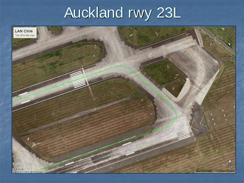
Auckland rwy 23L

Recap of ATSB safety report (2010)
Review other occurrences at
Abu Dhabi
Denmark
England
“Another look” at Auckland incident
How pilots can help
Summary

ATSB’s review of the issue (2010)
night
bad weather or reduced visibility
runway-taxiway configuration
take-off from displaced threshold or intersection
flight crew distraction or inattention
ATC clearance when entering runway
flight crew fatigue

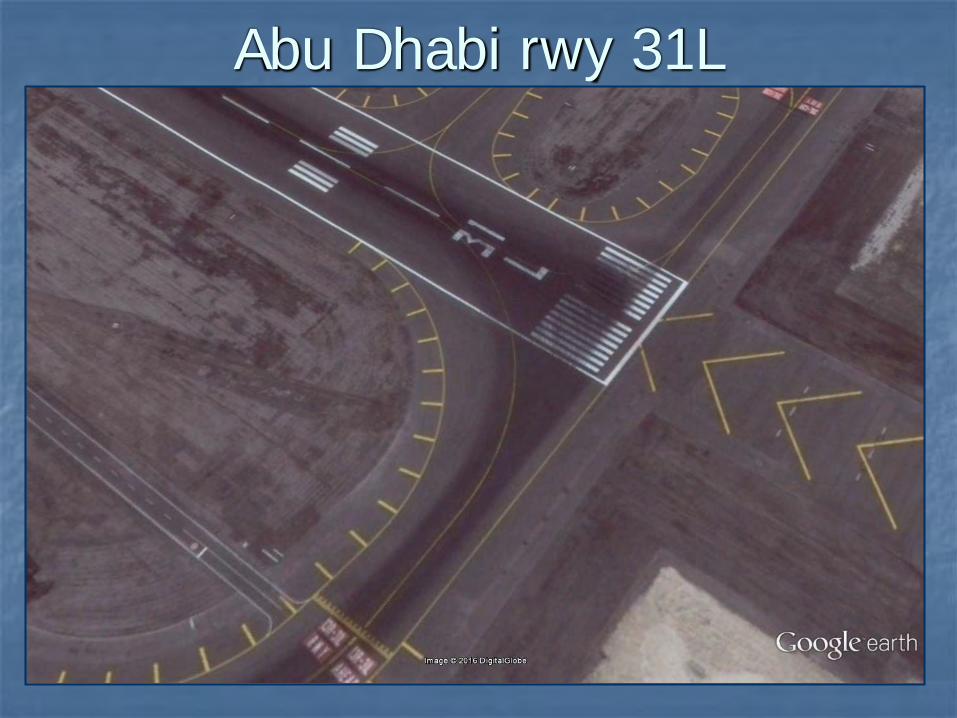
Abu Dhabi rwy 31L
Abu Dhabi rwy 31L
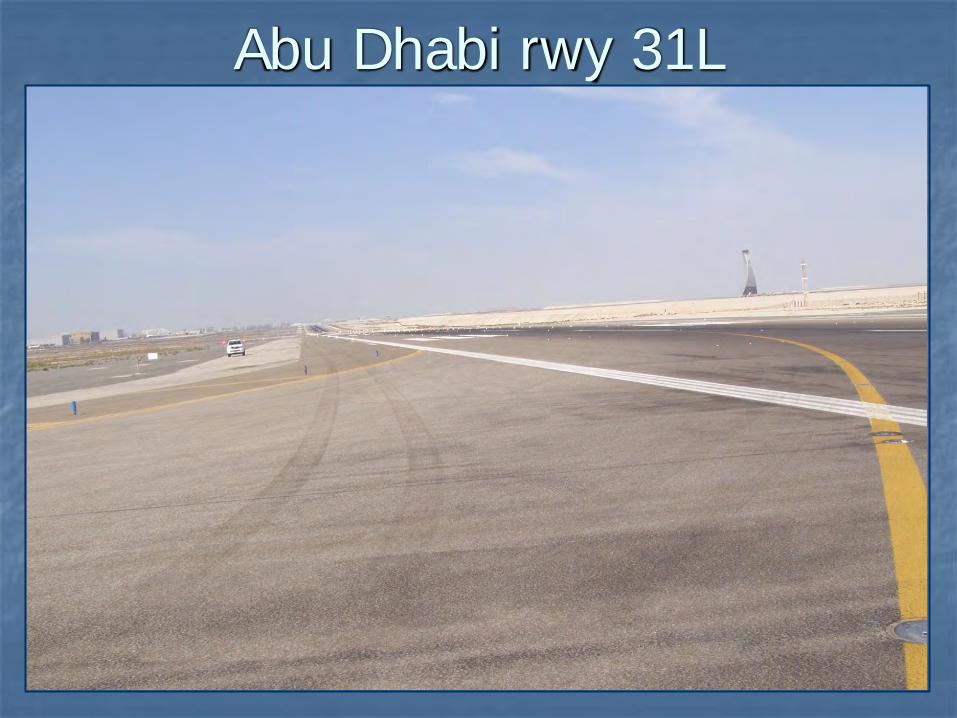
Abu Dhabi rwy 31L
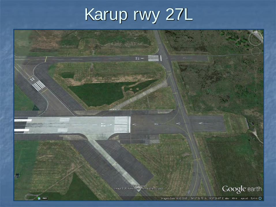
Karup rwy 27L

Biggin Hill rwy 03

Auckland rwy 23L
Aligned on the edge
Aligned at night Same view at day

ICAO Aerodrome Design Manual(Take-off guidance, Section 1.4.28)
“From a visual guidance standpoint, the take-off phase is not a problem. The pilot taxis into take-off position, using runway edge or centre line lights at night to centre the aircraft on the runway. Alignment guidance is provided by the runway centre line markings and/or lighting.”

Typical light fittings Recessed – Runway/taxiway centre
and runway edge Raised - Runway edge

Typical runway lights
(45 m runway width)
• Centreline - 15 m spacing, 10o beam width, 5,000 cd
• Edge lights - 60 m spacing, 10o beam width, 10,000 cd, toed-in 3.5o
• ICAO Isocandela diagrams

AAIB report – Biggin Hill

Approaching the edge line

Passing the edge

Correctly aligned

Taxiway lead-in line
Near holding point In the curve

Example of background lighting

ICAO Design manual
Two important factors must be considered in a lighting system:
1. The intensity setting must match ambient conditions.
2. The intensities of individual sections comprising the whole system must be matched.

Check how the runway lights are adjusted
Which lights are controlled in each group?
Taxiway lead-in setting same as straight?
Have the light intensities and background light levels been measured?
What guidance is provided for ATC to match runway lights with ambient?
If the pilots look at the runway lights and think:
“We are on the centreline”but they are actually on the edge,then they must have:
expected runway centreline lights focussed upon just a line of lightsbeen convinced that the picture
looked “right” - when it wasn’t discounted other lights that would
have shown a misalignment.

HAVE ANOTHER
LOOK

The pilots’ role
Pre-flight preparation Be wary of confusing intersections, Complete checks before runway entry Treat runway entry as a critical time Voice doubts and concerns Report incidents

Summary
Misalignments result from a misperception
Misperception can arise from confusing physical environment or lighting
The runway lighting systems must provide clear guidance to the centreline
Potential contributing factors are hazards – Report them

HAVE ANOTHER
LOOK

Slide 1
ANZSASI 2016
Runway misalignments“Take another look”
Barry StephensonPeter Williams
TAIC
Brisbane, 4 June 2016
• Take-off / attempted take-off when not aligned with centreline. • Misaligned landings can happen, but rare. • How could pilots make such a mistake? • Nearly always visual cues limited misperceptions error. AIM to build on known info about two factors in particular: • confusing taxiway/runway intersections • aerodrome lighting. At its heart, a misalignment is a flight crew error. A greater understanding of how these two factors can lead to pilots mistaking their position should help investigators, and can help pilots avoid such a mistake.

Slide 2
Auckland rwy 23L
From TAIC final report AO-2013-006, Airbus A340, CC-CQF, 18 May 2013. • Green line shows actual track (QAR). [Runway 05L used as taxiway.] • Cleared to take-off before got to holding point. • Taxiway centreline lights ‘disappeared’ when landing lights turned ON. • Taxiway centreline goes across threshold markings and runway number. • Wide area of pavement at runway entry, and wide (14 m) shoulders. • No transverse markings on inside of turn to show unusable pavement. • Captain turned sharply to line up with bright edge lights.

Slide 3
Recap of ATSB safety report (2010)
Review other occurrences at
Abu Dhabi
Denmark
England
“Another look” at Auckland incident
How pilots can help
Summary

Slide 4
ATSB’s review of the issue (2010)
night
bad weather or reduced visibility
runway-taxiway configuration
take-off from displaced threshold or intersection
flight crew distraction or inattention
ATC clearance when entering runway
flight crew fatigue
[Shown in a different order to the ATSB Safety Report AR-2009-033] • Compared to day, night cues are very degraded. • Pilots rely on airport lights and the patterns of lights. • Main runway-taxiway configuration issues are:
• confusing runway entry markings or lights • wide areas of pavement • lack of centreline lighting.
• How useful are markings at night? • Starting before displaced threshold, centreline arrows/chevrons seen? • If take-off from intersection, fewer markings to help.
Slide 5
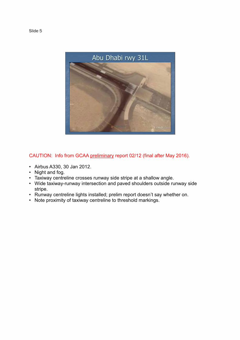
Abu Dhabi rwy 31L
CAUTION: Info from GCAA preliminary report 02/12 (final after May 2016). • Airbus A330, 30 Jan 2012. • Night and fog. • Taxiway centreline crosses runway side stripe at a shallow angle. • Wide taxiway-runway intersection and paved shoulders outside runway side
stripe. • Runway centreline lights installed; prelim report doesn’t say whether on. • Note proximity of taxiway centreline to threshold markings.
Slide 6
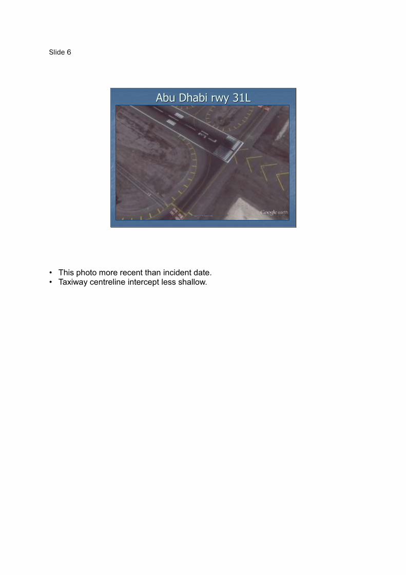
Abu Dhabi rwy 31L
• This photo more recent than incident date. • Taxiway centreline intercept less shallow.
Slide 7
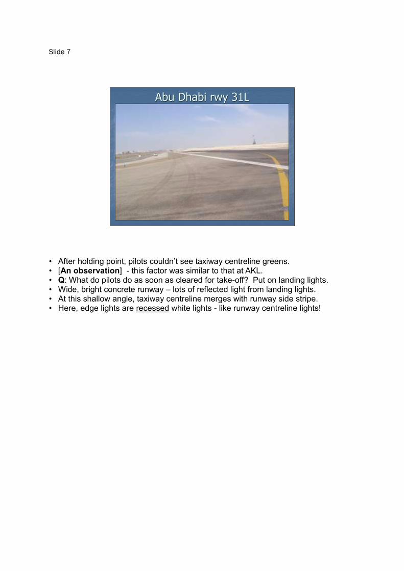
Abu Dhabi rwy 31L
• After holding point, pilots couldn’t see taxiway centreline greens. • [An observation] - this factor was similar to that at AKL. • Q: What do pilots do as soon as cleared for take-off? Put on landing lights. • Wide, bright concrete runway – lots of reflected light from landing lights. • At this shallow angle, taxiway centreline merges with runway side stripe. • Here, edge lights are recessed white lights - like runway centreline lights!

Slide 8
Karup rwy 27L
CAUTION: AIB Denmark preliminary report HCLJ510-2016-299. • 25 January 2016, ATR72-200, night and fog. • While in under-run, did take-off checks. Hit one red edge light before threshold. • Runway width 80m overall, but 45 m between side stripes. • Taxiway lights at 30%, runway edge 100%, centreline 30%. • Take-off commenced from threshold. Markings recognised? • [Observation] similarities to AKL. Wide runway entry and shoulders; runway centreline lighting ON; runway edge 100%. • ATSB safety review listed absence, not presence, of runway centreline lights as
factor.

Slide 9
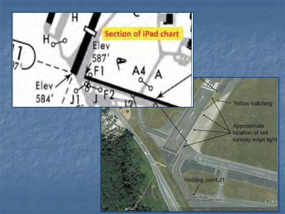
Biggin Hill rwy 03
AAIB final report Gulfstream III, N103CD, 24 Nov 2014 (Bulletin 12/2015). • Pilots expected centreline lighting, but none was installed. • Runway entry from holding point J1 presents risk of lining up on edge. • AIP warned of this risk; but pilots’ EFB (iPad) did not. • Dominant factor a ”visually compelling” line of edge lights, as at AKL. • Runway entry and line-up also prior to threshold (and markings). • AAIB recommended ICAO standard for runway edge lights to distinguish them.

Slide 10
• AIP and iPad (EFB) had misleading depiction of the aerodrome layout. • AIP warned of potential for a misalignment error, but the iPad did not. • Onus on aircraft operator to provide crews with correct information; not on EFB
provider to correctly interpret the AIP. • Possible safety issue whenever source docs are paraphrased or edited. • Example in TAIC report 10-007, loss of separation at Queenstown, re visual and
missed approach procedures.
Slide 11
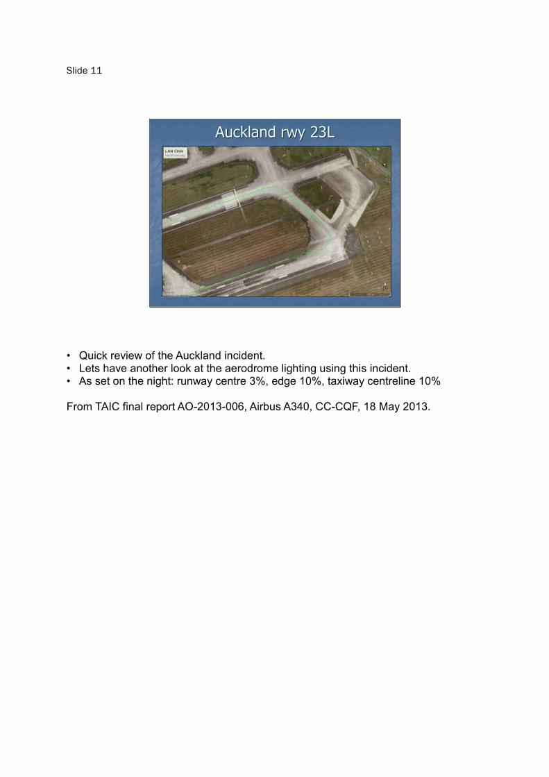
Auckland rwy 23L
• Quick review of the Auckland incident. • Lets have another look at the aerodrome lighting using this incident. • As set on the night: runway centre 3%, edge 10%, taxiway centreline 10% From TAIC final report AO-2013-006, Airbus A340, CC-CQF, 18 May 2013.

Slide 12
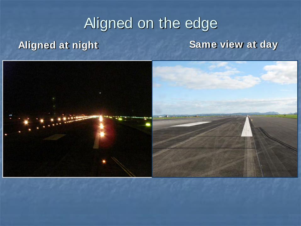
Aligned on the edge
Aligned at night Same view at day
• Auckland runway 23L- taxiway A1 intersection; as clear as night and day? • Captain >30,000 hrs , very familiar with Auckland. • International airport, lighting for Cat III low visibility operations. Our aim is to provide some insight on the characteristics of runway lighting. This may help future investigations.

Slide 13
ICAO Aerodrome Design Manual(Take-off guidance, Section 1.4.28)
“From a visual guidance standpoint,
the take-off phase is not a problem.
The pilot taxis into take-off position, using
runway edge or centre line lights at night to
centre the aircraft on the runway. Alignment
guidance is provided by the runway centre
line markings and/or lighting.”
ICAO Aerodrome Design Manual suggests take-off lighting guidance is not a problem for pilots. The total number of misalignments might support this premise, but it is still a problem. Why? Runway lighting intensity settings may be a factor.

Slide 14
Typical light fittings Recessed – Runway/taxiway centre
and runway edge Raised - Runway edge
• Important that investigators and pilots appreciate physical characteristics of the runway lights and their optics.
• Point source, radiates light in an even, spherical pattern. • Optics direct that light into a particular beam or beams for the designed purpose
using reflectors and lenses. • Typical fittings– recessed or raised. • Dual colour, bidirectional – other variations. • Runway edge light 2 x bi-directional beams and lower intensity omnidirectional
beam. • Recessed fitting used for edge lights at taxiway entrance and crossings
possible confusion.

Slide 15
Typical runway lights
(45 m runway width)
• Centreline - 15 m spacing, 10o beam width, 5,000 cd
• Edge lights - 60 m spacing, 10o beam width, 10,000 cd, toed-in 3.5o
• ICAO Isocandela diagrams
Typical runway lighting arrangement • Centre and edge fittings, 10 degree beam width, toe-in at 3.5 degrees,
bidirectional. • Explain isocandela diagram. • standard ICAO compliant fitting = average intensity 5,000 cd and edge is 10,000
cd @ 100% intensity setting. • Standard intensity ratio is 1:2 by design. The ratio was much higher in both
Auckland and Karup incidents. • Controllers should always set to same % intensity, but that depends on output at
lights being correct. • Important to maintain visual image – two lines of bright edge lights and less bright
centreline lights. Explain how apparent lighting intensity changes for pilot as aeroplane moves onto runway and across each line of lights. Notes Centreline fittings: • Recessed bi-directional, 15 m spacing • beam width 10o
• 5,000 cd average Edge lights fitting: • Recessed at intersections, otherwise raised above the surface. • Bi-directional, 60 m spacing • Beams 10o wide, centre toed-in 3.5o • 10,000 cd average (double the centreline intensity) • Raised fittings may include omnidirectional component.

• Recessed fittings near entrance taxiway may look like centreline lights.

Slide 16
AAIB report – Biggin Hill
This is another way of presenting the intensity differences. From AAIB report previously referred to. • intensity represented by the height of the bar graph. • Edge lights were interpreted by pilots as centreline. • BUT, symmetry was wrong. Centreline brighter than edge? Where were the right-
hand edge lights? AAIB report described the edge lights as a “visually compelling line”.

Slide 17
Approaching the edge line
Photos taken at Auckland a few days later in similar conditions, same relative lighting intensities, and from height of A340 cockpit. This photo - after passing holding point and entering runway 23L from taxiway A1. Note pilot cues towards the centreline. • Spacing differences obvious from side = clear guidance • Intensity differences - beam centres • Notice light spilling from manoeuvring area guidance system (MAGS) signs, also
dimmable on same circuit as edge lights. When seen in peripheral vision, could MAGS lights be interpreted as the right edge lights?
Slide 18
Passing the edge
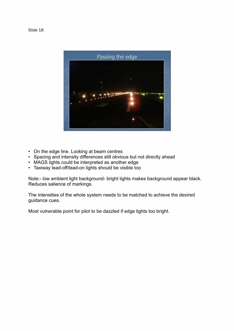
• On the edge line. Looking at beam centres • Spacing and intensity differences still obvious but not directly ahead • MAGS lights could be interpreted as another edge • Taxiway lead-off/lead-on lights should be visible too Note:- low ambient light background- bright lights makes background appear black. Reduces salience of markings. The intensities of the whole system needs to be matched to achieve the desired guidance cues. Most vulnerable point for pilot to be dazzled if edge lights too bright.
Slide 19
Correctly aligned
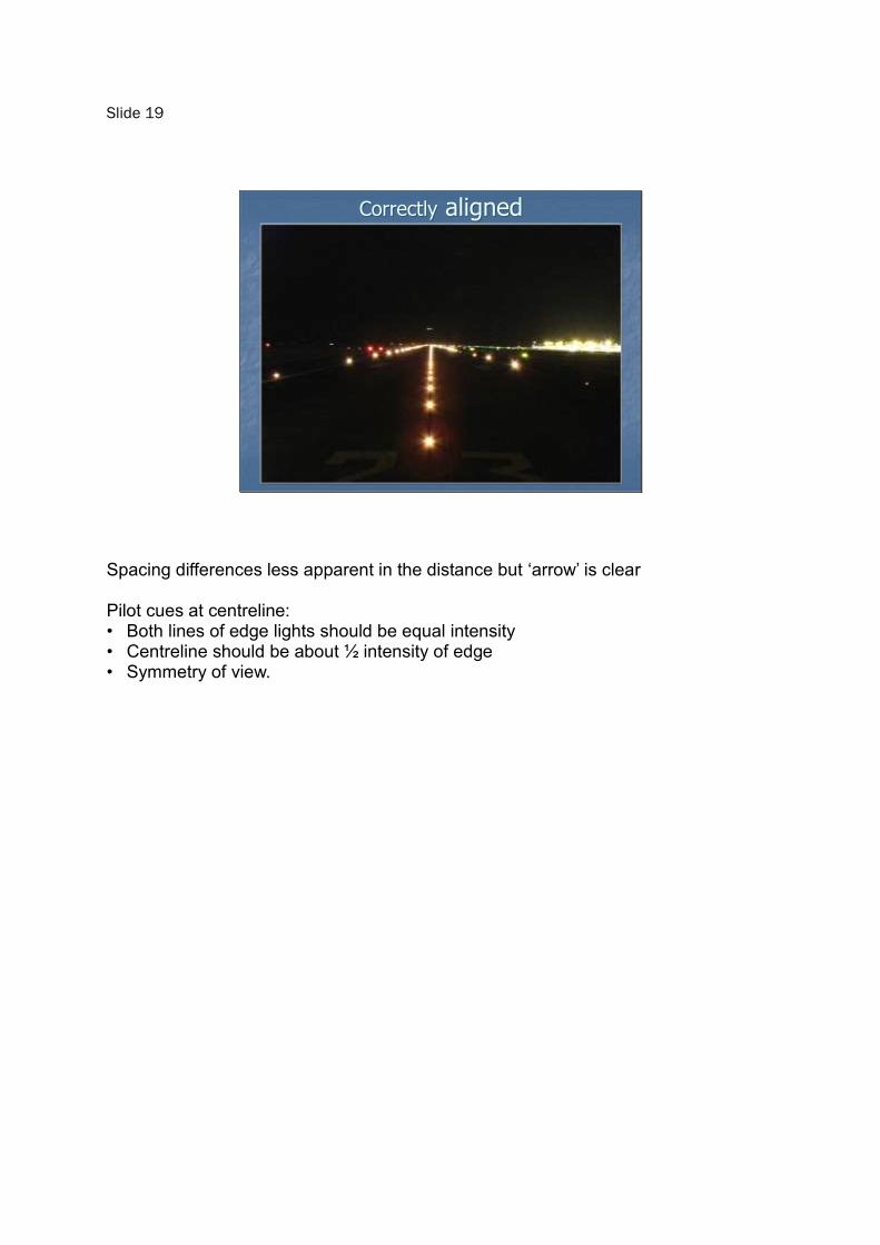
Spacing differences less apparent in the distance but ‘arrow’ is clear Pilot cues at centreline: • Both lines of edge lights should be equal intensity • Centreline should be about ½ intensity of edge • Symmetry of view.

Slide 20
• 50m radius taxiway curve and the beam angles of the centreline fittings • Comparison with narrow beam • About three lights should be visible at all times while taxing around the curve. Dashed extension line shows the cut-off to the edge of the beam centre Note the spacing, and toe-in angle. Important point: wider beams have lower intensity. This could make a difference if they are dimmed on same circuit. Sudden change in relative intensities at runway entry • During taxi to the holding point, - pilot sees high contrast with dark background, • Changes at runway entry - landing lights on - lower intensity lights, lower contrast
with background.
Slide 21
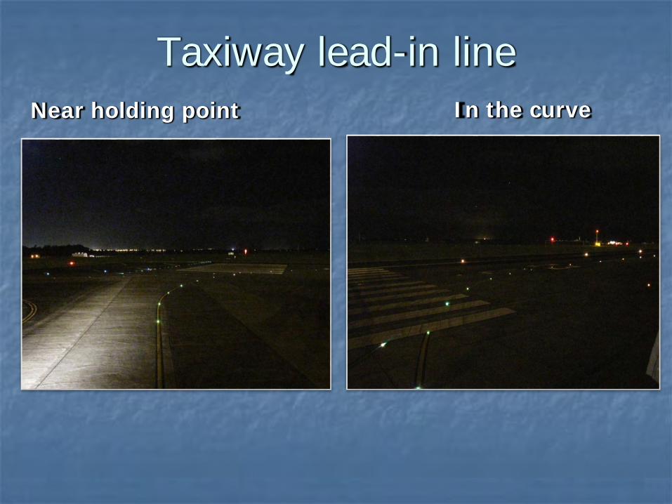
Taxiway lead-in line
Near holding point In the curve
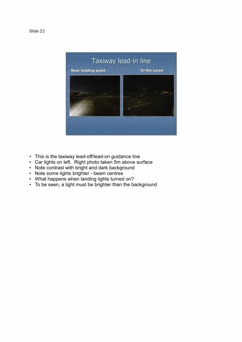
• This is the taxiway lead-off/lead-on guidance line • Car lights on left. Right photo taken 5m above surface • Note contrast with bright and dark background • Note some lights brighter - beam centres • What happens when landing lights turned on? • To be seen, a light must be brighter than the background
Slide 22
Example of background lighting
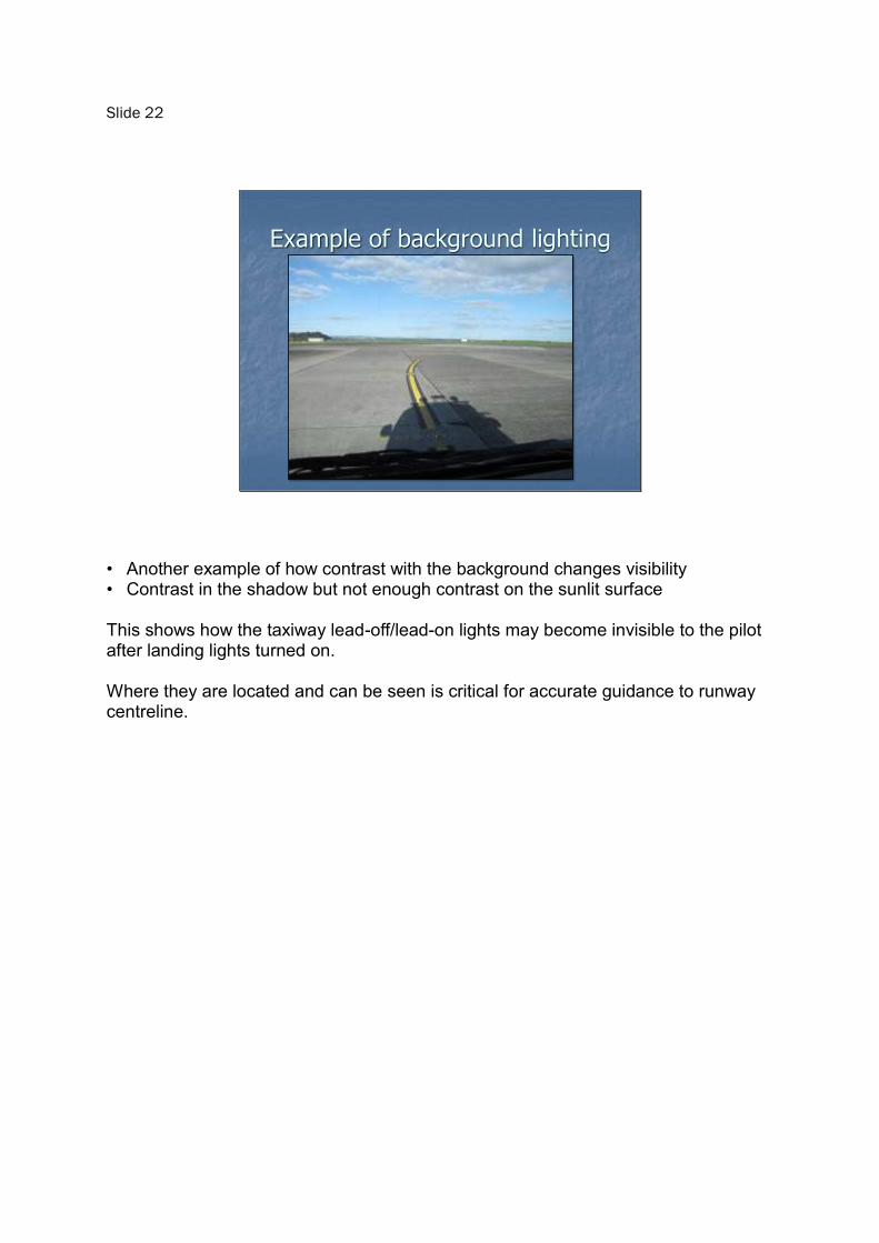
• Another example of how contrast with the background changes visibility • Contrast in the shadow but not enough contrast on the sunlit surface This shows how the taxiway lead-off/lead-on lights may become invisible to the pilot after landing lights turned on. Where they are located and can be seen is critical for accurate guidance to runway centreline.

Slide 23
ICAO Design manual
Two important factors must be considered in a lighting system:
1. The intensity setting must match ambient conditions.
2. The intensities of individual sections comprising the whole system must be matched.
To present a clear guidance image, the runway lighting intensity • must match ambient • relative intensities of all lights must be matched. To quote the ADM “These two factors ensure that the pilot neither misses a vital cue because the signal is too weak, nor is dazzled because certain lights are too bright for the prevailing conditions.” From ADM – Mechanics of seeing 1.2.30

Slide 24
Check how the runway lights are adjusted
Which lights are controlled in each group?
Taxiway lead-in setting same as straight?
Have the light intensities and background light levels been measured?
What guidance is provided for ATC to match runway lights with ambient?
Notes for investigators: • runway lighting intensity control will be provided at most aerodromes • ICAO provides recommended intensity settings, but expect (and determine) local
differences. These questions will help you to determine whether lighting intensity was a factor: • How are the lights grouped for intensity control: taxiway, edge, centreline? • Centreline and runway edge should be same intensity – could be on same circuit • MAGS lights separate or linked? • Taxiway lead-off/lead-on fittings and spacing same as straight sections? • Has the ambient lighting level been checked for different conditions and how does
the Tower select these steps? • Do the individual intensity settings match others to achieve the whole lighting
system? Having the correct absolute and relative lighting intensities is critical in order to convey the intended guidance. Note Auckland was - Runway centre 3%, Edge 10%, Taxiway centre 10%

Slide 25
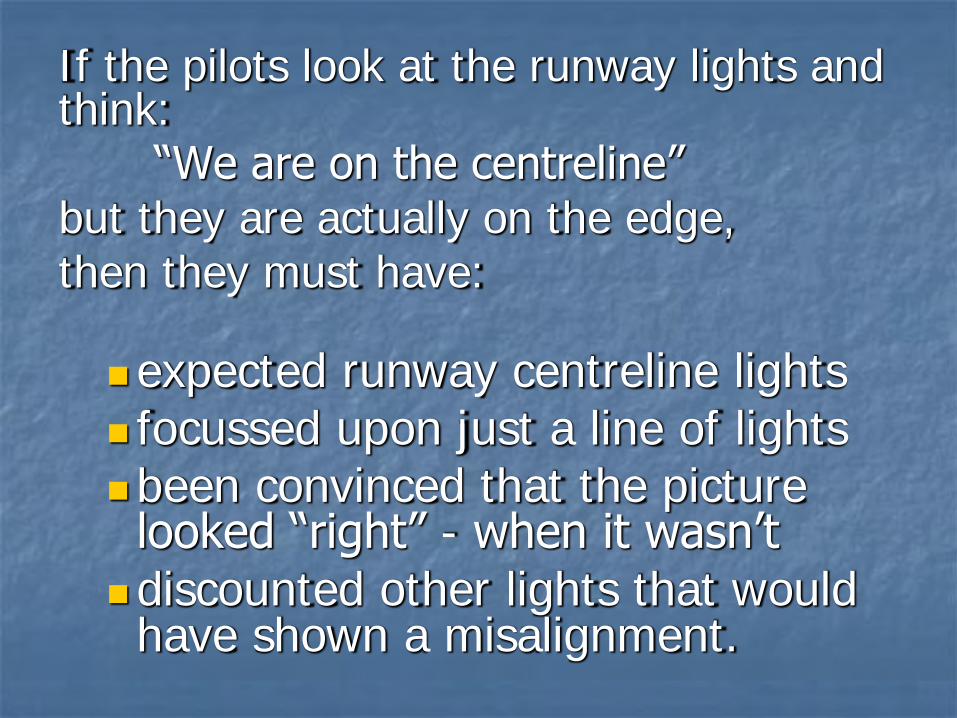
If the pilots look at the runway lights and think:
“We are on the centreline”but they are actually on the edge,then they must have:
expected runway centreline lights focussed upon just a line of lightsbeen convinced that the picture
looked “right” - when it wasn’t discounted other lights that would
have shown a misalignment.
• The ATSB review listed the absence of centreline lighting as a common factor. • Yet at Auckland, Abu Dhabi and Denmark centreline lighting was installed and on. • Did pilots just accept any “centreline”? • The Biggin Hill event reminds us of the importance of pre-flight preparation.

Slide 26
HAVE ANOTHER
LOOK
Slide 27
The pilots’ role
Pre-flight preparation Be wary of confusing intersections, Complete checks before runway entry Treat runway entry as a critical time Voice doubts and concerns Report incidents
• Adverse taxiway and runway and lighting factors are often present, but rarely lead to runway misalignments. Clearly flight crew have a role in preventing them.
• Brief the airport layout and know what lighting there is (NOTAMs too). • Reduce opportunities for distractions. • Be wary when taking off before the threshold or from an intersection. • These are some of the general considerations for all Runway Safety programmes.
Slide 28
Summary
Misalignments result from a misperception
Misperception can arise from confusing physical environment or lighting
The runway lighting systems must provide clear guidance to the centreline
Potential contributing factors are hazards – Report them
Other factors could be involved – have covered only two frequently seen factors. E.g. pilots’ eye sight, and whether they wear/should wear corrective lens. Was the crew pressed for time?

Slide 29
HAVE ANOTHER
LOOK