RULES FOR THE CONSTRUCTION AND … for the Construction and Classification of Steel ... 11.9.6...
15
CR Classification Society FOUNDED 1951 RULES FOR THE CONSTRUCTION AND CLASSIFICATION OF STEEL SHIPS 2013 Errata No.2 June 2015 CR CLASSIFICATION SOCIETY
Transcript of RULES FOR THE CONSTRUCTION AND … for the Construction and Classification of Steel ... 11.9.6...

CR Classification Society
FOUNDED 1951
RULES FOR THE CONSTRUCTION AND CLASSIFICATION OF STEEL SHIPS 2013 Errata No.2 June 2015 CR CLASSIFICATION SOCIETY

Rules for the Construction and Classification of Steel Ships, 2013 Errata No.2
06.2015 Page 1 / 14
[Part I] 1.6.2(f)(ii)
(ii) Survey of the hull structure IACS URZ23 Table 1II 2.17-1 provides a list of surveyable items for the hull structure and coating and is ap-plicable to this Society including:
[Part II] Table II 1-1
Table II 1-1 Test Requirements for Tanks and Boundaries Item
number
Tank or boundary
to be tested Test type Test head or pressure Remarks
1 Double bottom tanks
[4]
Leak &
Structural [1]
The greater of
- top of the overflow,
- to 2.4m above top of tank [2], or
- to bulkhead deck
… … … … …
20 Ballast ducts Leak &
Structural [1]
The greater of
- ballast pump maximum pressure, or
- setting of any pressure relief valve
Note : [1] Structural test is to be carried out for at least one tank of the same construction (i.e., same design and same
workmanship) on each vessel provided all subsequent tanks are tested for leaks by an air test. However, where structural adequacy of a tank was verified by structural testing, the subsequent vessels in the series (i.e., sister ships built in the same shipyard) may be exempted from such testing for other tanks which have the structural similarity to the tested tank, provided that the water-tightness in all boundaries of exempted tanks are verified by leak tests and thorough inspection is carried out. In any case, structural testing is to be carried out for at least one tank for each vessel in order to verify structural fabrication adequacy. (See 1.4.31.4.4 (b)(ii)(1))
[2] Top of tank is deck forming the top of the tank excluding any hatchways. [3] Hose Test may also be considered as a medium of the test. See 1.4.21.4.3 (b). [4] Including tanks arranged in accordance with the provisions of SOLAS regulation II-1/9.4. [5] Including duct keels and dry compartments arranged in accordance with the provisions of SOLAS regulation
II-1/9.4. [6] Where water tightness of watertight door has not been confirmed by prototype test, testing by filling watertight
spaces with water is to be carried out. See SOLAS regulation II-1/16.2 and MSC/Circ.1176. [7] Where a hose test is not practicable, other testing methods listed in 1.4.31.4.4 (d)(vii) through 1.4.31.4.4
(d)(ix) may be applicable subject to adequacy of such testing methods being verified. See SOLAS regulation II-1/11.1.
[8] As an alternative to the hose testing, other testing methods listed in 1.4.31.4.4 (d)(vii) through 1.4.31.4.4 (d)(ix) may be applicable subject to the adequacy of such testing methods being verified. See SOLAS regulation II-1/11.1.
[Part II] Table II 1-2
Table II 1-2 Additional Test Requirements for Special Service Ships/Tanks Item
number Type of
Ship/Tank Structures to be
tested Type of
Test Test Head or Pressure Remarks
1 Liquefied gas carriers
Cargo containment systems (See remarks)
See 1.4.31.4.4 (d)(i)
See 1.4.31.4.4 (d)(i) See also Table II 1-1 for other tanks and boundaries
2 Edible liquid carriers Independent tanks Leak &
Structural The greater of - top of the overflow, or

Rules for the Construction and Classification of Steel Ships, 2013 Errata No.2
06.2015 Page 2 / 14
- to 0.9m above top of tank [1]
3 Chemical carriers
Integral or independent cargo tanks
Leak & Structural
The greater of - to 2.4m above top of tank [1], or - to top of tank [1] plus setting of any pressure relief valve
Note : [1] Top of tank is deck forming the top of the tank excluding any hatchways.
[Part II] Table II 24-2
Table II 24-2 Allowable Surface Pressure, qa Bearing material qa (N/mm2)
Lignum-vitae 2.5 White metal, oil lubricated 4.5 Synthetic material with hardness between 60 and 70 Shore D (Note 1) 5.5 Steel (Note 2) and bronze and hot-pressed bronze-graphite materials 7.0
Notes: 1. Indentation hardness test at 23°C and 50% moisture, acc. according to a recognized standard. Syn-
thetic bearing materials are to be of approved type. 2. Stainless and wear-resistant steel in an approved combination with stock liner. Higher values than
given in the Table may be taken if they are verified by tests.
[Part II] II 33.2.1
33.2.1 The sloshing pressures given in 33.2.2, 33.2.3 and 33.2.6 are to be considered together with the general structural strength formulae given in 33.3, 33.4 and 33.5. The impact pressures pi given in 33.2.4 to 33.2.7 are to be used together with impact structural strength formulae given in 33.5.5 33.5.6.
[Part II] 33.3.7
33.3.7 Strengthening against liquid impact pressure in larger tanks If the ship side forms boundary of larger ballast or cargo tanks with free sloshing length ls > 0.13 L and or breadth bs > 0.56 B, the side structure is to have scantlings according to 33.5.5 33.5.6 for impact loads referred to in 33.2.1.
[Part III] 1.1.3
1.1.3 Except otherwise provided by this Chapter, the requirements for the construction of general ships given in the preceding Chapters of this Part Part II of the rules are to apply.
[Part III] 2A.2.1(f)(iv)
(4)(iv) In the case of bottom damage, a portion from the outflow from a cargo tank may be captured by nonoil compartments. This effect is approximated by application of the factor ( )DB iC for each tank, which shall be taken as follows:

Rules for the Construction and Classification of Steel Ships, 2013 Errata No.2
06.2015 Page 3 / 14
[Part III] 11.9.5
11.9.5 The depth of water under the keel in the testing area should be at least two times the vessel draft at amidships. 11.9.6 11.9.5 The steady bollard pull test requirements are as follows.
[Part III] 12.1.4(f)
(f) 9Specification and location of the fireman’s outfits provided.
[Part III] 12.4.11
12.4.11 Foam concentrate is to be sufficient for at least 30 minutes of simultaneous operation of both monitors at maximum capacity with assumed concentrated rate of 5%. The foam expansion ratio is not to exceed 12.
[Part III] 12.6.2
(a) Protective clothing of material to protect the skin from heat radiating. from the fire and from burns and scalding by steam. The outer surface is to be water-resistant. (b) from the fire and from burns and scalding by steam. The outer surface is to be water-resistant. (c) (b) Boots and gloves of rubber or other electrically non-conducting material. (d) (c) A rigid helmet providing effective protection against impact. (e) (d) An electric safety lamp (hand lantern) of an approved type with a minimum operating period of three hours. (f) (e) An axe having an insulated handle. (g) (f) A self-contained breathing apparatus, which is to be capable of functioning for a period of at least 30 minutes and having a capacity of at least 1200 liters of free air. Spare, fully charged air bottles are to be provided at the rate of at least one set per required apparatus. (h) (g) For each breathing apparatus, a fireproof lifeline of sufficient length and strength is to be provided capable of being attached by means of a snap-hook to the harness of the apparatus or to a separate belt, in order to prevent the breathing apparatus becoming detached when the life-line is operated.
[Part IV] 3.5.2(a)(iii)(1)
(1) For the crankpin fillet σBH = ±(αB • σBN)
where: σBH = alternating bending stress in crankpin fillet (N/mm2); αB = stress concentration factor for bending in crankpin fillet (determination see 3.5.3).

Rules for the Construction and Classification of Steel Ships, 2013 Errata No.2
06.2015 Page 4 / 14
[Part IV] Table IV 4-1
Table IV 4-1 Hydraulic Test Pressure on Deck Machinery and Pump Parts
Parts to be Tested Test Pressure, MPa Steering gear:
Steam reciprocating steering engine. Hydraulic steering gear, pump case, cylinder etc.
Windlass: Steam reciprocating windlass engine. Diesel windlass engine. Hydraulic pump and motor.
Reciprocating compressors: Air Compressor: Cylinder, liner, cover, inter- and fter-coolers.
Compressed air side. Cooling water space.
Refriagerant compressor.
Pump: Pump prime mover, steam or diesel engine. Pump casing.
Piping: Group-I and -II pipes and fittings.
See 2.9.1 of this Part. 1.5 W or W + 7, whichever is smaller. See 2.9.1 of this Part. See 3.10.1 of this Part. 1.5 W or W + 7, whichever is smaller. 1.5 W 0.4 but not less than 1.5 W See Part X See 2.9.1 and 3.10.1 of this Part. 0.4 but not less than 1.5 W. See Part VI.
Where: W = Design pressure and/or maximum working pressure for therespective parts, in MPa.
[Part IV] 7.2.1(a)
(a) For propeller blade of conventional design, the required blade thickness is to comply with the follow-ing formula:
t=1.17NBZS
10HkkKC6
21m1×
[Part V] 3.2.1
3.2.1 Flat and end plates
Rules for the Construction and Classification of Steel Ships, 2013 Errata No.2
06.2015 Page 5 / 14
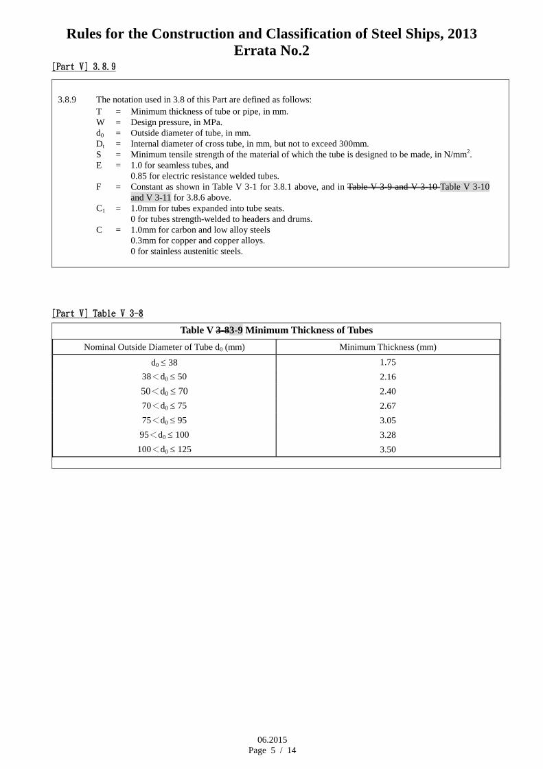
[Part V] 3.8.9
3.8.9 The notation used in 3.8 of this Part are defined as follows: T = Minimum thickness of tube or pipe, in mm. W = Design pressure, in MPa. d0 = Outside diameter of tube, in mm. Dt = Internal diameter of cross tube, in mm, but not to exceed 300mm. S = Minimum tensile strength of the material of which the tube is designed to be made, in N/mm2. E = 1.0 for seamless tubes, and
0.85 for electric resistance welded tubes. F = Constant as shown in Table V 3-1 for 3.8.1 above, and in Table V 3-9 and V 3-10 Table V 3-10
and V 3-11 for 3.8.6 above. C1 = 1.0mm for tubes expanded into tube seats.
0 for tubes strength-welded to headers and drums. C = 1.0mm for carbon and low alloy steels
0.3mm for copper and copper alloys. 0 for stainless austenitic steels.
[Part V] Table V 3-8
Table V 3-83-9 Minimum Thickness of Tubes Nominal Outside Diameter of Tube d0 (mm) Minimum Thickness (mm)
d0 ≤ 38 1.75 38<d0 ≤ 50 2.16 50<d0 ≤ 70 2.40 70<d0 ≤ 75 2.67 75<d0 ≤ 95 3.05
95<d0 ≤ 100 3.28 100<d0 ≤ 125 3.50

Rules for the Construction and Classification of Steel Ships, 2013 Errata No.2
06.2015 Page 6 / 14
[Part V] Table V 3-9
Table V 3-93-10 Constant F for Tubes within Heat Exchanger
Kind of Material Design Temperature (℃)
Grade Min T. S. (N/mm2)
Up to 50 75 100 125 150 175 200 225 250 275 300
Seamless copper tubes (phosphorous-oxidized) 205 4.77 5.86 6.21 6.21 6.41 7.59 10.25 - - - -
Seamless brass tubes 315 4.63 4.63 4.63 4.63 4.63 4.70 13.13 - - - -
355 4.33 4.38 4.38 4.44 4.44 7.89 16.15 - - - -
Seamless copper-nickel tubes
275 4.04 4.04 4.04 4.37 4.51 4.66 4.77 5.00 5.09 5.73 6.71
315 4.32 4.38 4.38 4.44 4.50 4.50 4.70 485 4.85 5.00 5.25 5.53
365 4.51 4.63 4.74 4.87 4.93 5.07 5.21 5.29 5.45 5.53 5.62
Steel pipes See Part XI See Table V 3-103-11
Notes: 1. Value F may be determined by interpolation at intermediate temperature. 2. Constant F for other materials may be acceptable upon special consideration.
[Part V] Table V 3-10
Table V 3-103-11 Constant F for Steel Pipes
Material Design Temperature (℃)
Kind Grade Min T.S. (N/mm2)
Up to 100 150 200 250 300 350 375 400 425 450 475 500 525 550
Carbon steel pipes
P11 P12 P13
370 410 480
3.01 2.97 3.08
3.25 3.20 3.31
3.52 3.47 3.61
3.85 3.83 3.93
4.25 4.27 4.10
4.74 4.56 4.25
- - - - - - - -
Low alloy steel pipes
P21 P22 P23 P24
380 410 410 410
3.19 3.39 3.39 3.39
3.39 3.53 3.53 3.53
3.62 3.69 3.69 3.69
3.92 3.90 3.90 3.90
4.27 4.14 4.14 4.14
4.47 4.41 4.41 4.41
4.58 4.51 4.51 4.51
4.75 4.61 4.61 4.61
4.94 4.82 4.82 4.82
5.21 5.13 5.13 5.13
5.43 5.39 5.39 5.39
5.85 5.77 5.77 5.77
- 7.45 7.32 7.32
- 10.79 10.25 10.00
Notes: 1. Value F may be determined by interpolation at intermediate temperature. 2. Constant F for other materials may be acceptable upon special consideration.

Rules for the Construction and Classification of Steel Ships, 2013 Errata No.2
06.2015 Page 7 / 14
[Part V] 5.1.6
5.1.6 Where boilers are located on tween decks in machinery spaces and boiler rooms are not separated from a machinery space by watertight bulkheads, the tween decks are to be provided with coamings at least 7675mm in height. This area may be drained to the bilges.
[Part VI] 3.5.11
3.5.11 In ships of 4,000 tons gross gross tonnage and above other than oil tankers and in oil tankers of 150 tons gross gross tonnage and above, no ballast water is to be carried in any fuel oil tank.
[Part VII] 2.5.11(a)
(a) The system is to be a loud speaker installation enabling the broadcast of messages to all spaces where crew members or passengers, or both, are normally present and to muster stations. The system is to provide for the broad-cast of messages from the navigation bridge and other places on board as may be required by the Society, with an override function so that all emergency messages may be broadcast if any loudspeaker in the spaces concerned has been turned off, its volume has been turned down or the public address system is in used for other purpose emergen-cy messages may be broadcast if any loudspeaker in the spaces concerned has been turned off, its volume has been turned down or the public address system is in used for other purpose. The system is to be installed with regard to acoustically marginal conditions and is not to require any action from the addressee. The system is to be protected against unauthorized use.
[Part VII] 7.3.1
7.3.1 The secondary terminal voltage difference between no load and the rated current with a unity power factor, expressed as a percentage of the no load secondary voltage, is not to exceed the following values: For up to less than5 kVA per phase 5% For 5 kVA and over per phase 2.5%
[Part VII] 12.1.1(a)
12.1.1 In addition to the requirements of other relevant Chapters the special requirements of this Chapter apply to: (a) Oil tankers for the carriage in bulk of oil cargoes having a flash point below not exceeding 60°C (closed cup test).
[Part VII] 12.8.8
12.8.8 Zones within 5 m of any pressure/vacuum valve required by 5.9.1(b)(i) of Part VI, or at any height above and within a 10 m radius (measured horizontally) of any vent required by 5.9.1(b)(ii) of Part VI, and below and within a 3 m radius of any such vent not of the high velocity type. (a) Intrinsically safe equipment
Rules for the Construction and Classification of Steel Ships, 2013 Errata No.2
06.2015 Page 8 / 14
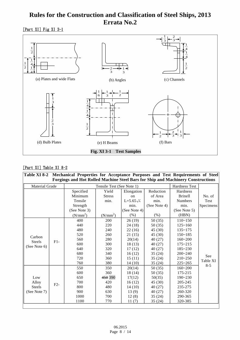
[Part XI] Fig XI 3-1
(a) Plates and wide Flats (b) Angles (c) Channels
(d) Bulb Plates (e) H Beams
(f) Bars
Fig. XI 3-1 Test Samples
32 3
1
32
31
31
31
32
32
21
31 2
1 6
1
21
21 4
1
41
41
41
21
41
41
21
[Part XI] Table XI 8-2
Table XI 8-2 Mechanical Properties for Acceptance Purposes and Test Requirements of Steel Forgings and Hot Rolled Machine Steel Bars for Ship and Machinery Constructions
Material Grade Tensile Test (See Note 1) Hardness Test
No. of Test
Specimens
Specified Minimum
Tensile Strength
(See Note 3) (N/mm2)
Yield Stress min.
(N/mm2)
Elongation on
L=5.65 A min.
(See Note 4) (%)
Reduction of Area
min. (See Note 4)
(%)
Hardness Brinell
Numbers min.
(See Note 5) (HBN)
Carbon Steels
(See Note 6) F1-
400 440 480 520 560 600 640 680 720 760
200 220 240 260 280 300 320 340 360 380
26 (19) 24 (18) 22 (16) 21 (15) 20(14) 18 (13) 17 (12) 16 (12) 15 (11) 14 (10)
50 (35) 50 (35) 45 (30) 45 (30) 40 (27) 40 (27) 40 (27) 35 (24) 35 (24) 35 (24)
110~150 125~160 135~175 150~185 160~200 175~215 185~230 200~240 210~250 225~265
See Table XI
8-5
Low Alloy Steels
(See Note 7)
F2-
550 600 650 700 800 900
1000 1100
350 360
450 390 420 480 630 700 770
20(14) 18 (14) 17(12) 16 (12) 14 (10) 13 (9) 12 (8) 11 (7)
50 (35) 50 (35) 50(35) 45 (30) 40 (27) 40 (27) 35 (24) 35 (24)
160~200 175-215 190~230 205-245 235-275 260-320 290-365 320-385
Rules for the Construction and Classification of Steel Ships, 2013 Errata No.2
06.2015 Page 9 / 14
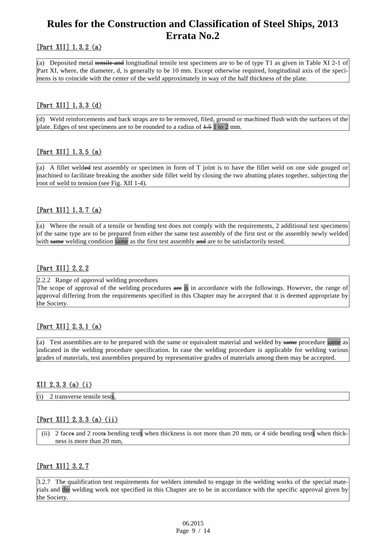
[Part XII] 1.3.2 (a)
(a) Deposited metal tensile and longitudinal tensile test specimens are to be of type T1 as given in Table XI 2-1 of Part XI, where, the diameter, d, is generally to be 10 mm. Except otherwise required, longitudinal axis of the speci-mens is to coincide with the center of the weld approximately in way of the half thickness of the plate.
[Part XII] 1.3.3 (d)
(d) Weld reinforcements and back straps are to be removed, filed, ground or machined flush with the surfaces of the plate. Edges of test specimens are to be rounded to a radius of 1.5 1 to 2 mm.
[Part XII] 1.3.5 (a)
(a) A fillet welded test assembly or specimen in form of T joint is to have the fillet weld on one side gouged or machined to facilitate breaking the another side fillet weld by closing the two abutting plates together, subjecting the root of weld to tension (see Fig. XII 1-4).
[Part XII] 1.3.7 (a)
(a) Where the result of a tensile or bending test does not comply with the requirements, 2 additional test specimens of the same type are to be prepared from either the same test assembly of the first test or the assembly newly welded with same welding condition same as the first test assembly and are to be satisfactorily tested.
[Part XII] 2.2.2
2.2.2 Range of approval welding procedures The scope of approval of the welding procedures are is in accordance with the followings. However, the range of approval differing from the requirements specified in this Chapter may be accepted that it is deemed appropriate by the Society.
[Part XII] 2.3.1 (a)
(a) Test assemblies are to be prepared with the same or equivalent material and welded by same procedure same as indicated in the welding procedure specification. In case the welding procedure is applicable for welding various grades of materials, test assemblies prepared by representative grades of materials among them may be accepted.
XII 2.3.3 (a) (i)
(i) 2 transverse tensile tests,
[Part XII] 2.3.3 (a) (ii)
(ii) 2 faces and 2 roots bending tests when thickness is not more than 20 mm, or 4 side bending tests when thick-ness is more than 20 mm,
[Part XII] 3.2.7
3.2.7 The qualification test requirements for welders intended to engage in the welding works of the special mate-rials and the welding work not specified in this Chapter are to be in accordance with the specific approval given by the Society.

Rules for the Construction and Classification of Steel Ships, 2013 Errata No.2
06.2015 Page 10 / 14
[Part XII] Table XII 4-8
Table XII 4-8 Approval Tests for Semi-Automatic Welding Materials Test Assemblies No. of Test Specimens
Tests Welding Positions
Dia. of Wire to be used (mm)
No. of set
Plate Thickness
(mm) Dimensions
to be taken from each Test Assembly
for Tests Deposited
Metal Downhand Largest dia. 1
20 See Fig. XII 4-1
1 − Deposited tensile and
1 − 3 Impact (See Notes 1 and 2) Smallest dia. 1
Butt Weld (See Notes 3
and 7)
Downhand (See Note 4)
1st run: smallest dia. Remaining runs: largest dia. 1
15 ∼ 20 See Fig. XII 4-2
1 − Transverse tensile,
Horizontal (see Note 5)
1st run: smallest dia. Remaining runs: 1 1 − Face bending,
1 − Root bending Vertical Largest dia. available for
the position concerned. 1 and 1 − 3 Impact
Overhead 1 (See Note 6)
Fillet Weld (See Note 8) Downhand
1.2 1 20 See
Fig. XII 4-3
3 − Macro-etching/ Hardness and
1.6 1 2 − Fracture
[Part XII] 5.6.4
5.6.4 Preparations and executions of weldings, and preheating, stress relieving and inspections of welded construction part of machinery are to be done in accordance with the requirements stated in 5.1 to 5.5 of this Chapter, if applicable.
[Part XII] 5.7.4 (d)
(d) Where pressure vessels are made of materials having a superior notch toughness, stress relieving may be omitted when specially approved by the Society in a particular case.

Rules for the Construction and Classification of Steel Ships, 2013 Errata No.2
06.2015 Page 11 / 14
[Part XII] Fig. XII 5-5
clad plate
clad plate
Assembly subjected to high stresses: Root beads can be welded with over-alloyed welding materials and the top layer with ordinary stainless steel welding material, or root bead is welded with a normal strength steel welding material and the top layer with over-alloyed welding material. Fig. XII 5-5 Examples on welding sequence
[Cargo Gear] 2.4
2.4 The following certificates are required to be attached to the Register:
(a) Certificate of Test and Thorough Examination of Derricks, Winches, and their Accessory Gear (ILO Form 2)(CGGC 17).
(b) Certificate of Test and Thorough Examination of Derricks, Winches, and their Accessory Gear, for operation in Union Purchase (ILO Form 2(U))(CGGC 17U).
(c) Certificate of Test and Thorough Examination of Cranes or Hoists and their Accessory Gear (ILO Form 3)(CGGC 18).
(d) Certificate of Test and Thorough Examination of Cargo Lifts/Cargo Ramps and their Accessory Gear (ILO Form 3LR)(CGGC 18LR).
(e) Certificate of Test and Thorough Examination of Loose Gear (ILO Form 4)(CGGC 19).
(f) Certificate of Test and Thorough Examination of Rope(CGGC 20).
[Cargo Gear] Table 4.2
Table 4.2 Proof Load for cargo gear assembly
Safe working load SWL (t) Proof load (t)
SWL<20 1.25 × SWL
20 ≤SWL<50 SWL + 5
50 ≤SWL<100 1.1 × SWL
100 <≤SWL Load as considered appropriate by the Society

Rules for the Construction and Classification of Steel Ships, 2013 Errata No.2
06.2015 Page 12 / 14
[Cargo Gear] 8.3(c)
(c) Buckling strength For member subjected to compression, the value obtained from the following formula is not to exceed the al-lowable stress σa given in Table 8.2.
1.15 ωσbσc N/mm2
where: σbσc = Axial compressive stress, N/mm2. ω = Coefficient calculated by the formula in Table 8.3 and Table 8.4 for the slenderness ratio and type of the
member concerned.
[Cargo Gear] 8.3(d)
(d) Combined compressive stress The compressive stress due to combination of the compressive stress due to axial compression and that due to bending moment is to meet the following formula:
[(σc/σca)+(σb/σa) ]≤ 1.0
where: σa = Allowable bending stress given in Table 8.2, N/mm2. σca = Allowable compressive stress to be taken as a quotient of σa divided 1.15, N/mm2. σb = Compressive stress due to bending moment, N/mm2. σc = Compressive stress due to axial compression, N/mm2.
[Cargo Gear] 8.4(b)(ii)
(ii) The section modulus of stayed posts at the base may be the value specified in reduced by the value obtained from the following formula:
10(h3/dm) ∑R cm3
where: h = As specified in 8.4(a). dm = Outside diameter of the post at the base in the direction in which R assumes minimum in the slewing
range for the formula in 8.4(b)(i)(1) or in the axis parallel to the athwartship direction of the ship for the formula in 8.4(b)(i)(2), cm.
∑R = Sum of the values obtained from the following formula for each effective stay: (ds
2a2)/(l02ls2)
ds = Diameter of the wire rope for stays, mm. ls = Length of stays between the upper and lower ends, m. lo = Length equal to ls reduced by the value obtained from the following formula:
0.045 ds+0.26 m a = Length of horizontal projection of the stays measured in the same direction as the measurement of dm.

Rules for the Construction and Classification of Steel Ships, 2013 Errata No.2
06.2015 Page 13 / 14
[Cargo Gear] 8.4(e)(i)(3)
(3) The section modulus about the horizontal axis is to be the value obtained from the formula in 8.4(b)(i)(2) multiplied by the coefficient obtained from the following formula. Where this coefficient exceeds 0.2, it may be taken as 0.2.
0.25(γ'/c') where: γ' = specified in 8.4(b)(iii)(2). c' = Ration of the actual section modulus ,cm3,of the post at the base about the axis parallel to the longitu-
dinal direction of the ship to that obtained from the formula in 8.4(b)(i)(2).
[Cargo Gear] 8.5(b)(i)
(i) The moment of inertia of section at an arbitrary position at a distance of x (m), from the center of eye fitting at derrick heel is not to be less than obtained from the following formula. Where a doubling plate is fitted for a sufficient length, 70% of the doubling plate may be added to D(x) and A(x) in the formula.
I(x)=CBPl2{1-3.136[(x/l)-0.5]2}+1000D(x)l1xWg cosθ/[2ln(σ0-10P/A(x)]
where: I(x) = Required moment of inertia of section at a distance of x, m, from the derrick heel, cm4. CB = As specified in 8.5(a). P = Axial compression of boom specified in 8.5(a)(i)(1), kN. l = Effective length of boom, m. n = Sum of sheaves of cargo block for cargo fall (except cargo block for cargo relief). W = Safe working load as specified in 8.4(b)(i)(1), t. θ = Allowable minimum angle of boom, degree. l1 = Distance between the eye fittings for whipped rigging, m. See Fig. 8.1. D(x) = Outside diameter of derrick boom at a distance of x (m) from the boom heel minus plate thickness , cm. A(x) = Sectional area of derrick boom at a distance of x (m) from the boom heel, cm2. σ0 = Value given in Table 8.11, N/mm2.
[Cargo Gear] 9.1(d)(ii)
(ii) The inertial force is to be obtained by multiplying the sum of the mass of the moving parts and the hoisting load (in slewing motion, the load is assumed to be at the top of jib) by the following coefficient depending on the condition of motion. In the case of traveling by driven wheels, however, this inertial force need not exceed 15% of the driving wheel load.
Level luffing motions : 0.01V1/2
Traversing or traveling motions: 0.008V1/2
Slewing motions : 0.006 V1/2
Where V = Velocity of motion concerned to be determined by the designer,, m/min

Rules for the Construction and Classification of Steel Ships, 2013 Errata No.2
06.2015 Page 14 / 14
[Cargo Gear] Table 9.3
Table 9.3 Shape Factor Cs Type of area under wind pressure Cs
Truss of angle
φ<0.1 0.1≤φ<0.3 0.3≤φ<0.9 0.9≤φ
2.0 1.8 1.6 2.0
Plate girder or box girder
(l/h)<5
5≤ (l/h)<10
10≤ (l/h)<15
15≤ (l/h)<25
1.2 1.3 1.4 1.6
Cylindrical member or truss of cylindrical member
d q1/2<1.0 1.0≤d q1/2
1.2 0.7
Note: φ = Repleteness ratio equal to the ratio of projected area under wind pressure to the projected area surrounded by
the outer contour of the area under wind pressure. l = Length of plate girder or box girder, m. h = Height of plate girder or box girder looked at from windward, m. d = Outer diameter of cylindrical member, m. q = Value calculated by the following formula :
(gChV2/16)×10-3 kPa
h
h l
l
h