ENGINEERING DRAWINGS (S/S BY ASME-Y14.100, ASME-Y14.24, ASME-Y14.35M, AND ASME-14.34M)

ASME BPVC. I I I .1 .NG-2015
Div is ion 1 — Subsect ion NGCore Suppor t S t r uctures
SECTION I I IRules for Construct ion ofNuclear Faci l i ty Components
2015 ASME Boiler andPressure Vessel CodeAn International Code
Copyrighted material licensed to University of Toronto by Thomson Scientific, Inc. (www.techstreet.com). This copy downloaded on 2015-07-14 21:43:59 -0500 by authorized user logan ahlstrom. No further reproduction or distribution is permitted.

IIIRULES FOR CONSTRUCTIONOF NUCLEAR FACILITYCOMPONENTS
Division 1 - Subsection NG
Core Support StructuresASME Boiler and Pressure Vessel Committeeon Nuclear Power
AN INTERNATIONAL CODE
2015 ASME Boiler &Pressure Vessel Code2015 Edition July 1, 2015
Two Park Avenue • New York, NY • 10016 USA
Copyrighted material licensed to University of Toronto by Thomson Scientific, Inc. (www.techstreet.com). This copy downloaded on 2015-07-14 21:43:59 -0500 by authorized user logan ahlstrom. No further reproduction or distribution is permitted.

Date of Issuance: July 1, 2015
This international code or standard was developed under procedures accredited as meeting the criteria forAmerican National Standards and it is an American National Standard. The Standards Committee that approvedthe code or standard was balanced to assure that individuals from competent and concerned interests havehad an opportunity to participate. The proposed code or standard was made available for public review and com-ment that provides an opportunity for additional public input from industry, academia, regulatory agencies, andthe public-at-large.ASME does not “approve,” “rate,” or “endorse” any item, construction, proprietary device, or activity.ASME does not take any position with respect to the validity of any patent rights asserted in connection with any
items mentioned in this document, and does not undertake to insure anyone utilizing a standard against liabilityfor infringement of any applicable letters patent, nor assume any such liability. Users of a code or standard areexpressly advised that determination of the validity of any such patent rights, and the risk of infringement of suchrights, is entirely their own responsibility.Participation by federal agency representative(s) or person(s) affiliated with industry is not to be interpreted as
government or industry endorsement of this code or standard.ASME accepts responsibility for only those interpretations of this document issued in accordance with the es-
tablished ASME procedures and policies, which precludes the issuance of interpretations by individuals.The endnotes and preamble in this document (if any) are part of this American National Standard.
ASME collective membership mark
Certification Mark
The above ASME symbol is registered in the U.S. Patent Office.
“ASME” is the trademark of The American Society of Mechanical Engineers.
No part of this document may be reproduced in any form, in an electronicretrieval system or otherwise, without the prior written permission of the
publisher.
Library of Congress Catalog Card Number: 56-3934Printed in the United States of America
Adopted by the Council of The American Society of Mechanical Engineers, 1914; latest edition 2015.
The American Society of Mechanical EngineersTwo Park Avenue, New York, NY 10016-5990
Copyright © 2015 byTHE AMERICAN SOCIETY OF MECHANICAL ENGINEERS
All rights reserved
Copyrighted material licensed to University of Toronto by Thomson Scientific, Inc. (www.techstreet.com). This copy downloaded on 2015-07-14 21:43:59 -0500 by authorized user logan ahlstrom. No further reproduction or distribution is permitted.

TABLE OF CONTENTS
List of Sections . . . . . . . . . . . . . . . . . . . . . . . . . . . . . . . . . . . . . . . . . . . . . . . . . . . . . . . . . . . . . . . . . . . . . . . . . . . . . . viForeword . . . . . . . . . . . . . . . . . . . . . . . . . . . . . . . . . . . . . . . . . . . . . . . . . . . . . . . . . . . . . . . . . . . . . . . . . . . . . . . . . . . viiiStatement of Policy on the Use of the Certification Mark and Code Authorization in Advertising . . . . . . . . . . xStatement of Policy on the Use of ASME Marking to Identify Manufactured Items . . . . . . . . . . . . . . . . . . . . . . xSubmittal of Technical Inquiries to the Boiler and Pressure Vessel Standards Committees . . . . . . . . . . . . . . . xiPersonnel . . . . . . . . . . . . . . . . . . . . . . . . . . . . . . . . . . . . . . . . . . . . . . . . . . . . . . . . . . . . . . . . . . . . . . . . . . . . . . . . . . . xiiiOrganization of Section III . . . . . . . . . . . . . . . . . . . . . . . . . . . . . . . . . . . . . . . . . . . . . . . . . . . . . . . . . . . . . . . . . . . . . xxxSummary of Changes . . . . . . . . . . . . . . . . . . . . . . . . . . . . . . . . . . . . . . . . . . . . . . . . . . . . . . . . . . . . . . . . . . . . . . . . . xxxiiiList of Changes in Record Number Order . . . . . . . . . . . . . . . . . . . . . . . . . . . . . . . . . . . . . . . . . . . . . . . . . . . . . . . . xxxivCross-Referencing and Stylistic Changes in the Boiler and Pressure Vessel Code . . . . . . . . . . . . . . . . . . . . . . . xxxv
Article NG-1000 Introduction . . . . . . . . . . . . . . . . . . . . . . . . . . . . . . . . . . . . . . . . . . . . . . . . . . . . . . . . . . . . . . 1NG-1100 Scope . . . . . . . . . . . . . . . . . . . . . . . . . . . . . . . . . . . . . . . . . . . . . . . . . . . . . . . . . . . . . . . . . . . . . 1
NG-1110 Aspects of Construction Covered by These Rules . . . . . . . . . . . . . . . . . . . . . . . . . . . . . . . . 1NG-1120 Definition of Structures and Application of These Rules to Them . . . . . . . . . . . . . . . . . . 1NG-1130 Boundaries of Jurisdiction Applicable to This Subsection . . . . . . . . . . . . . . . . . . . . . . . . . 1
Article NG-2000 Material . . . . . . . . . . . . . . . . . . . . . . . . . . . . . . . . . . . . . . . . . . . . . . . . . . . . . . . . . . . . . . . . . . 4NG-2100 General Requirements for Material . . . . . . . . . . . . . . . . . . . . . . . . . . . . . . . . . . . . . . . . . . . . 4
NG-2110 Scope of Principal Terms Employed . . . . . . . . . . . . . . . . . . . . . . . . . . . . . . . . . . . . . . . . . . . 4NG-2120 Material for Core Support Structures . . . . . . . . . . . . . . . . . . . . . . . . . . . . . . . . . . . . . . . . . . 4NG-2130 Certification of Material . . . . . . . . . . . . . . . . . . . . . . . . . . . . . . . . . . . . . . . . . . . . . . . . . . . . . 4NG-2140 Welding Material . . . . . . . . . . . . . . . . . . . . . . . . . . . . . . . . . . . . . . . . . . . . . . . . . . . . . . . . . . . 5NG-2150 Material Identification . . . . . . . . . . . . . . . . . . . . . . . . . . . . . . . . . . . . . . . . . . . . . . . . . . . . . . 5NG-2160 Deterioration of Material in Service . . . . . . . . . . . . . . . . . . . . . . . . . . . . . . . . . . . . . . . . . . . 5NG-2170 Heat Treatment to Enhance Impact Properties . . . . . . . . . . . . . . . . . . . . . . . . . . . . . . . . . . 5NG-2180 Procedures for Heat Treatment of Material . . . . . . . . . . . . . . . . . . . . . . . . . . . . . . . . . . . . . 5NG-2190 Temporary Attachment Material . . . . . . . . . . . . . . . . . . . . . . . . . . . . . . . . . . . . . . . . . . . . . . 5
NG-2200 Material Test Coupons and Specimens for Ferritic Steel Material . . . . . . . . . . . . . . . . . . 5NG-2210 Heat Treatment Requirements . . . . . . . . . . . . . . . . . . . . . . . . . . . . . . . . . . . . . . . . . . . . . . . 5NG-2220 Procedure for Obtaining Test Coupons and Specimens for Quenched and Tempered Ma-
terial . . . . . . . . . . . . . . . . . . . . . . . . . . . . . . . . . . . . . . . . . . . . . . . . . . . . . . . . . . . . . . . . . . . 6NG-2300 Fracture Toughness Requirements for Material . . . . . . . . . . . . . . . . . . . . . . . . . . . . . . . . . 7
NG-2310 Material to Be Impact Tested . . . . . . . . . . . . . . . . . . . . . . . . . . . . . . . . . . . . . . . . . . . . . . . . . 7NG-2320 Impact Test Procedures . . . . . . . . . . . . . . . . . . . . . . . . . . . . . . . . . . . . . . . . . . . . . . . . . . . . . 8NG-2330 Test Requirements and Acceptance Standards . . . . . . . . . . . . . . . . . . . . . . . . . . . . . . . . . . 8NG-2340 Number of Impact Tests Required . . . . . . . . . . . . . . . . . . . . . . . . . . . . . . . . . . . . . . . . . . . . 9NG-2350 Retests . . . . . . . . . . . . . . . . . . . . . . . . . . . . . . . . . . . . . . . . . . . . . . . . . . . . . . . . . . . . . . . . . . . 10NG-2360 Calibration of Instruments and Equipment . . . . . . . . . . . . . . . . . . . . . . . . . . . . . . . . . . . . . 10
NG-2400 Welding Material . . . . . . . . . . . . . . . . . . . . . . . . . . . . . . . . . . . . . . . . . . . . . . . . . . . . . . . . . . . 10NG-2410 General Requirements . . . . . . . . . . . . . . . . . . . . . . . . . . . . . . . . . . . . . . . . . . . . . . . . . . . . . . 10NG-2420 Required Tests . . . . . . . . . . . . . . . . . . . . . . . . . . . . . . . . . . . . . . . . . . . . . . . . . . . . . . . . . . . . . 11NG-2430 Weld Metal Tests . . . . . . . . . . . . . . . . . . . . . . . . . . . . . . . . . . . . . . . . . . . . . . . . . . . . . . . . . . . 12NG-2440 Storage and Handling of Welding Material . . . . . . . . . . . . . . . . . . . . . . . . . . . . . . . . . . . . . 14
NG-2500 Examination and Repair of Core Support Structure Material . . . . . . . . . . . . . . . . . . . . . . 14NG-2510 Examination of Core Support Structure Material . . . . . . . . . . . . . . . . . . . . . . . . . . . . . . . . 14NG-2520 Examination After Quenching and Tempering . . . . . . . . . . . . . . . . . . . . . . . . . . . . . . . . . . . 14NG-2530 Examination and Repair of Plate . . . . . . . . . . . . . . . . . . . . . . . . . . . . . . . . . . . . . . . . . . . . . . 14NG-2540 Examination and Repair of Forgings and Bars . . . . . . . . . . . . . . . . . . . . . . . . . . . . . . . . . . 16NG-2550 Examination and Repair of Seamless and Welded Tubular Products and Fittings . . . . . 18
iii
Copyrighted material licensed to University of Toronto by Thomson Scientific, Inc. (www.techstreet.com). This copy downloaded on 2015-07-14 21:43:59 -0500 by authorized user logan ahlstrom. No further reproduction or distribution is permitted.
NG-2570 Examination and Repair of Statically and Centrifugally Cast Products . . . . . . . . . . . . . . . 19NG-2580 Examination of Threaded Structural Fasteners . . . . . . . . . . . . . . . . . . . . . . . . . . . . . . . . . . 22
NG-2600 Material Organizations’ Quality System Programs . . . . . . . . . . . . . . . . . . . . . . . . . . . . . . . 23NG-2610 Documentation and Maintenance of Quality System Programs . . . . . . . . . . . . . . . . . . . . . 23
Article NG-3000 Design . . . . . . . . . . . . . . . . . . . . . . . . . . . . . . . . . . . . . . . . . . . . . . . . . . . . . . . . . . . . . . . . . . . 24NG-3100 General Design . . . . . . . . . . . . . . . . . . . . . . . . . . . . . . . . . . . . . . . . . . . . . . . . . . . . . . . . . . . . . 24NG-3110 Loading Criteria . . . . . . . . . . . . . . . . . . . . . . . . . . . . . . . . . . . . . . . . . . . . . . . . . . . . . . . . . . . . 24NG-3120 Special Considerations . . . . . . . . . . . . . . . . . . . . . . . . . . . . . . . . . . . . . . . . . . . . . . . . . . . . . . 25NG-3130 General Design Rules . . . . . . . . . . . . . . . . . . . . . . . . . . . . . . . . . . . . . . . . . . . . . . . . . . . . . . . 25
NG-3200 Design by Analysis . . . . . . . . . . . . . . . . . . . . . . . . . . . . . . . . . . . . . . . . . . . . . . . . . . . . . . . . . 28NG-3210 Design Criteria . . . . . . . . . . . . . . . . . . . . . . . . . . . . . . . . . . . . . . . . . . . . . . . . . . . . . . . . . . . . . 28NG-3220 Stress Limits for Other Than Threaded Structural Fasteners . . . . . . . . . . . . . . . . . . . . . . 33NG-3230 Stress Limits for Threaded Structural Fasteners . . . . . . . . . . . . . . . . . . . . . . . . . . . . . . . . . 42
NG-3300 Core Support Structure Design . . . . . . . . . . . . . . . . . . . . . . . . . . . . . . . . . . . . . . . . . . . . . . . 45NG-3310 General Requirements . . . . . . . . . . . . . . . . . . . . . . . . . . . . . . . . . . . . . . . . . . . . . . . . . . . . . . 45NG-3320 Design Considerations . . . . . . . . . . . . . . . . . . . . . . . . . . . . . . . . . . . . . . . . . . . . . . . . . . . . . . 45NG-3350 Design for Welded Construction . . . . . . . . . . . . . . . . . . . . . . . . . . . . . . . . . . . . . . . . . . . . . . 45
Article NG-4000 Fabrication and Installation . . . . . . . . . . . . . . . . . . . . . . . . . . . . . . . . . . . . . . . . . . . . . . . . 50NG-4100 General Requirements . . . . . . . . . . . . . . . . . . . . . . . . . . . . . . . . . . . . . . . . . . . . . . . . . . . . . . 50NG-4110 Introduction . . . . . . . . . . . . . . . . . . . . . . . . . . . . . . . . . . . . . . . . . . . . . . . . . . . . . . . . . . . . . . . 50NG-4120 Certification of Material and Fabrication by Certificate Holder . . . . . . . . . . . . . . . . . . . . . 50NG-4130 Repair of Material . . . . . . . . . . . . . . . . . . . . . . . . . . . . . . . . . . . . . . . . . . . . . . . . . . . . . . . . . . 50
NG-4200 Forming, Fitting, and Aligning . . . . . . . . . . . . . . . . . . . . . . . . . . . . . . . . . . . . . . . . . . . . . . . . 51NG-4210 Cutting, Forming, and Bending . . . . . . . . . . . . . . . . . . . . . . . . . . . . . . . . . . . . . . . . . . . . . . . 51NG-4230 Fitting and Aligning . . . . . . . . . . . . . . . . . . . . . . . . . . . . . . . . . . . . . . . . . . . . . . . . . . . . . . . . . 52
NG-4300 Welding Qualifications . . . . . . . . . . . . . . . . . . . . . . . . . . . . . . . . . . . . . . . . . . . . . . . . . . . . . . 52NG-4310 General Requirements . . . . . . . . . . . . . . . . . . . . . . . . . . . . . . . . . . . . . . . . . . . . . . . . . . . . . . 52NG-4320 Welding Qualifications, Records, and Identifying Stamps . . . . . . . . . . . . . . . . . . . . . . . . . 53NG-4330 General Requirements for Welding Procedure Qualification Tests . . . . . . . . . . . . . . . . . . 53
NG-4400 Rules Governing Making, Examining, and Repairing Welds . . . . . . . . . . . . . . . . . . . . . . . . 56NG-4410 Precautions to Be Taken Before Welding . . . . . . . . . . . . . . . . . . . . . . . . . . . . . . . . . . . . . . . 56NG-4420 Rules for Making Welded Joints . . . . . . . . . . . . . . . . . . . . . . . . . . . . . . . . . . . . . . . . . . . . . . 56NG-4430 Welding of Temporary Attachments and Their Removal . . . . . . . . . . . . . . . . . . . . . . . . . . 57NG-4450 Repair of Weld Metal Defects . . . . . . . . . . . . . . . . . . . . . . . . . . . . . . . . . . . . . . . . . . . . . . . . 57
NG-4500 Brazing . . . . . . . . . . . . . . . . . . . . . . . . . . . . . . . . . . . . . . . . . . . . . . . . . . . . . . . . . . . . . . . . . . . 59NG-4600 Heat Treatment . . . . . . . . . . . . . . . . . . . . . . . . . . . . . . . . . . . . . . . . . . . . . . . . . . . . . . . . . . . . 59NG-4610 Welding Preheat Requirements . . . . . . . . . . . . . . . . . . . . . . . . . . . . . . . . . . . . . . . . . . . . . . . 59NG-4620 Postweld Heat Treatment . . . . . . . . . . . . . . . . . . . . . . . . . . . . . . . . . . . . . . . . . . . . . . . . . . . . 59NG-4630 Heat Treatment of Welds Other Than the Final Postweld Heat Treatment . . . . . . . . . . . 63NG-4650 Heat Treatment After Bending or Forming . . . . . . . . . . . . . . . . . . . . . . . . . . . . . . . . . . . . . 63NG-4660 Heat Treatment of Electroslag Welds . . . . . . . . . . . . . . . . . . . . . . . . . . . . . . . . . . . . . . . . . . 63
NG-4700 Mechanical Joints . . . . . . . . . . . . . . . . . . . . . . . . . . . . . . . . . . . . . . . . . . . . . . . . . . . . . . . . . . . 63NG-4710 Threaded Structural Fasteners . . . . . . . . . . . . . . . . . . . . . . . . . . . . . . . . . . . . . . . . . . . . . . . 63NG-4720 Temporary Fasteners and Their Removal . . . . . . . . . . . . . . . . . . . . . . . . . . . . . . . . . . . . . . 63
Article NG-5000 Examination . . . . . . . . . . . . . . . . . . . . . . . . . . . . . . . . . . . . . . . . . . . . . . . . . . . . . . . . . . . . . . 64NG-5100 General Requirements for Examination . . . . . . . . . . . . . . . . . . . . . . . . . . . . . . . . . . . . . . . . 64NG-5110 Procedures, Qualifications, and Evaluation . . . . . . . . . . . . . . . . . . . . . . . . . . . . . . . . . . . . . 64NG-5120 Time of Examination of Welds . . . . . . . . . . . . . . . . . . . . . . . . . . . . . . . . . . . . . . . . . . . . . . . . 64NG-5130 Examination of Weld Edge Preparation Surfaces . . . . . . . . . . . . . . . . . . . . . . . . . . . . . . . . 64
NG-5200 Required Examination of Welds . . . . . . . . . . . . . . . . . . . . . . . . . . . . . . . . . . . . . . . . . . . . . . 66NG-5210 Permissible Examination Methods . . . . . . . . . . . . . . . . . . . . . . . . . . . . . . . . . . . . . . . . . . . . 66NG-5220 Requirements for Radiography or Ultrasonic and Liquid Penetrant or Magnetic Particle
Examination . . . . . . . . . . . . . . . . . . . . . . . . . . . . . . . . . . . . . . . . . . . . . . . . . . . . . . . . . . . . . 66NG-5230 Requirements for Liquid Penetrant or Magnetic Particle Examination . . . . . . . . . . . . . . 66NG-5260 Requirements for Surface Visual Examination . . . . . . . . . . . . . . . . . . . . . . . . . . . . . . . . . . . 66
iv
Copyrighted material licensed to University of Toronto by Thomson Scientific, Inc. (www.techstreet.com). This copy downloaded on 2015-07-14 21:43:59 -0500 by authorized user logan ahlstrom. No further reproduction or distribution is permitted.

NG-5270 Hard Surfacing . . . . . . . . . . . . . . . . . . . . . . . . . . . . . . . . . . . . . . . . . . . . . . . . . . . . . . . . . . . . . 67NG-5300 Acceptance Standards . . . . . . . . . . . . . . . . . . . . . . . . . . . . . . . . . . . . . . . . . . . . . . . . . . . . . . . 67
NG-5320 Radiographic Acceptance Standards . . . . . . . . . . . . . . . . . . . . . . . . . . . . . . . . . . . . . . . . . . . 67NG-5330 Ultrasonic Acceptance Standards . . . . . . . . . . . . . . . . . . . . . . . . . . . . . . . . . . . . . . . . . . . . . 67NG-5340 Magnetic Particle Acceptance Standards . . . . . . . . . . . . . . . . . . . . . . . . . . . . . . . . . . . . . . . 67NG-5350 Liquid Penetrant Acceptance Standards . . . . . . . . . . . . . . . . . . . . . . . . . . . . . . . . . . . . . . . . 68NG-5360 Visual Examination Acceptance Standards . . . . . . . . . . . . . . . . . . . . . . . . . . . . . . . . . . . . . . 68
NG-5500 Qualifications and Certification of Nondestructive Examination Personnel . . . . . . . . . . . 68NG-5510 General Requirements . . . . . . . . . . . . . . . . . . . . . . . . . . . . . . . . . . . . . . . . . . . . . . . . . . . . . . 68NG-5520 Personnel Qualification, Certification, and Verification . . . . . . . . . . . . . . . . . . . . . . . . . . . 68NG-5530 Records . . . . . . . . . . . . . . . . . . . . . . . . . . . . . . . . . . . . . . . . . . . . . . . . . . . . . . . . . . . . . . . . . . . 69
Article NG-8000 Nameplates, Stamping With Certification Mark, and Reports . . . . . . . . . . . . . . . . . . 70NG-8100 Requirements . . . . . . . . . . . . . . . . . . . . . . . . . . . . . . . . . . . . . . . . . . . . . . . . . . . . . . . . . . . . . . 70
FIGURESNG-1131-1 Jurisdictional Boundary Between Core Support Structure and Reactor Pressure Vessel . . . 2NG-2433.1-1 Weld Metal Delta Ferrite Content . . . . . . . . . . . . . . . . . . . . . . . . . . . . . . . . . . . . . . . . . . . . . . . . 15NG-3221-1 Stress Categories and Limits of Stress Intensities for Service Levels A and B . . . . . . . . . . . 34NG-3224-1 Stress Categories and Limits of Stress Intensities for Service Level C . . . . . . . . . . . . . . . . . . 38NG-3232-1 Stress Intensity Limits for Design of Threaded Structural Fasteners . . . . . . . . . . . . . . . . . . . 43NG-3351(a)-1 Typical Locations of Joints of Several Categories . . . . . . . . . . . . . . . . . . . . . . . . . . . . . . . . . . . 46NG-3351(a)-2 Typical Welded Joint Category Locations . . . . . . . . . . . . . . . . . . . . . . . . . . . . . . . . . . . . . . . . . . 47NG-4427-1 Fillet and Socket Weld Details and Dimensions . . . . . . . . . . . . . . . . . . . . . . . . . . . . . . . . . . . . 58
TABLESNG-2331(a)-1 Required Cv Values for Core Structure Material With 2 in. (50 mm) Maximum Thickness
(Other than Threaded Structural Fasteners) . . . . . . . . . . . . . . . . . . . . . . . . . . . . . . . . . . . . 9NG-2333-1 Required Cv Values for Threaded Structural Fastener Material . . . . . . . . . . . . . . . . . . . . . . 9NG-2432.1-1 Sampling of Welding Materials for Chemical Analysis . . . . . . . . . . . . . . . . . . . . . . . . . . . . . . 13NG-2432.2-1 Welding Material Chemical Analysis . . . . . . . . . . . . . . . . . . . . . . . . . . . . . . . . . . . . . . . . . . . . . 14NG-3217-1 Classification of Stress Intensities for Some Typical Cases . . . . . . . . . . . . . . . . . . . . . . . . . . 32NG-3352-1 Permissible Welded Joints and Design Factors . . . . . . . . . . . . . . . . . . . . . . . . . . . . . . . . . . . . 49NG-4622.1-1 Mandatory Requirements for Postweld Heat Treatment (PWHT) of Welds . . . . . . . . . . . . 60NG-4622.4(c)-1 Alternative Holding Temperatures and Times . . . . . . . . . . . . . . . . . . . . . . . . . . . . . . . . . . . . . 61NG-4622.7(b)-1 Exemptions to Mandatory PWHT . . . . . . . . . . . . . . . . . . . . . . . . . . . . . . . . . . . . . . . . . . . . . . . 62NG-5111-1 Thickness, IQI Designations, Essential Holes, and Wire Diameters . . . . . . . . . . . . . . . . . . . . 65
ENDNOTES . . . . . . . . . . . . . . . . . . . . . . . . . . . . . . . . . . . . . . . . . . . . . . . . . . . . . . . . . . . . . . . . . . . . . . . . . . . . . . . . . 71
v
Copyrighted material licensed to University of Toronto by Thomson Scientific, Inc. (www.techstreet.com). This copy downloaded on 2015-07-14 21:43:59 -0500 by authorized user logan ahlstrom. No further reproduction or distribution is permitted.

ð15Þ LIST OF SECTIONSSECTIONSI Rules for Construction of Power Boilers
II Materials• Part A — Ferrous Material Specifications• Part B — Nonferrous Material Specifications• Part C — Specifications for Welding Rods, Electrodes, and Filler Metals• Part D — Properties (Customary)• Part D — Properties (Metric)
III Rules for Construction of Nuclear Facility Components• Subsection NCA — General Requirements for Division 1 and Division 2• Appendices• Division 1– Subsection NB — Class 1 Components– Subsection NC — Class 2 Components– Subsection ND — Class 3 Components– Subsection NE — Class MC Components– Subsection NF — Supports– Subsection NG — Core Support Structures– Subsection NH — Class 1 Components in Elevated Temperature Service*
• Division 2 — Code for Concrete Containments• Division 3 — Containments for Transportation and Storage of Spent Nuclear Fuel and High Level RadioactiveMaterial and Waste
• Division 5 — High Temperature Reactors
IV Rules for Construction of Heating Boilers
V Nondestructive Examination
VI Recommended Rules for the Care and Operation of Heating Boilers
VII Recommended Guidelines for the Care of Power Boilers
VIII Rules for Construction of Pressure Vessels• Division 1• Division 2 — Alternative Rules• Division 3 — Alternative Rules for Construction of High Pressure Vessels
IX Welding, Brazing, and Fusing Qualifications
X Fiber-Reinforced Plastic Pressure Vessels
XI Rules for Inservice Inspection of Nuclear Power Plant Components
XII Rules for Construction and Continued Service of Transport Tanks
* The 2015 Edition of Section III is the last edition in which Section III, Division 1, Subsection NH, Class 1 Components in Elevated TemperatureService, will be published. The requirements located within Subsection NH have been moved to Section III, Division 5, Subsection HB, Subpart Bfor the elevated temperature construction of Class A components.
vi
Copyrighted material licensed to University of Toronto by Thomson Scientific, Inc. (www.techstreet.com). This copy downloaded on 2015-07-14 21:43:59 -0500 by authorized user logan ahlstrom. No further reproduction or distribution is permitted.

INTERPRETATIONS
Interpretations of the Code have historically been posted in January and July at http://cstools.asme.org/interpreta-tions.cfm. Interpretations issued during the previous two calendar years are included with the publication of the applic-able Section of the Code in the 2015 Edition. Interpretations of Section III, Divisions 1 and 2 and Section III Appendicesare included with Subsection NCA.
Following the 2015 Edition, interpretations will not be included in editions; they will be issued in real time in ASME'sInterpretations Database at http://go.asme.org/Interpretations. Historical BPVC interpretations may also be found inthe Database.
CODE CASES
The Boiler and Pressure Vessel Code committees meet regularly to consider proposed additions and revisions to theCode and to formulate Cases to clarify the intent of existing requirements or provide, when the need is urgent, rules formaterials or constructions not covered by existing Code rules. Those Cases that have been adopted will appear in theappropriate 2015 Code Cases book: “Boilers and Pressure Vessels” or “Nuclear Components.” Supplements will be sentor made available automatically to the purchasers of the Code Cases books up to the publication of the 2017 Code.
vii
Copyrighted material licensed to University of Toronto by Thomson Scientific, Inc. (www.techstreet.com). This copy downloaded on 2015-07-14 21:43:59 -0500 by authorized user logan ahlstrom. No further reproduction or distribution is permitted.

ð15Þ FOREWORD*
In 1911, The American Society of Mechanical Engineers established the Boiler and Pressure Vessel Committee to for-mulate standard rules for the construction of steam boilers and other pressure vessels. In 2009, the Boiler and PressureVessel Committee was superseded by the following committees:(a) Committee on Power Boilers (I)(b) Committee on Materials (II)(c) Committee on Construction of Nuclear Facility Components (III)(d) Committee on Heating Boilers (IV)(e) Committee on Nondestructive Examination (V)(f) Committee on Pressure Vessels (VIII)(g) Committee on Welding, Brazing, and Fusing (IX)(h) Committee on Fiber-Reinforced Plastic Pressure Vessels (X)(i) Committee on Nuclear Inservice Inspection (XI)(j) Committee on Transport Tanks (XII)(k) Technical Oversight Management Committee (TOMC)Where reference is made to “the Committee” in this Foreword, each of these committees is included individually and
collectively.The Committee’s function is to establish rules of safety relating only to pressure integrity, which govern the
construction** of boilers, pressure vessels, transport tanks, and nuclear components, and the inservice inspection of nu-clear components and transport tanks. The Committee also interprets these rules when questions arise regarding theirintent. The technical consistency of the Sections of the Code and coordination of standards development activities of theCommittees is supported and guided by the Technical Oversight Management Committee. This Code does not addressother safety issues relating to the construction of boilers, pressure vessels, transport tanks, or nuclear components, orthe inservice inspection of nuclear components or transport tanks. Users of the Code should refer to the pertinent codes,standards, laws, regulations, or other relevant documents for safety issues other than those relating to pressure integ-rity. Except for Sections XI and XII, and with a few other exceptions, the rules do not, of practical necessity, reflect thelikelihood and consequences of deterioration in service related to specific service fluids or external operating environ-ments. In formulating the rules, the Committee considers the needs of users, manufacturers, and inspectors of pressurevessels. The objective of the rules is to afford reasonably certain protection of life and property, and to provide a marginfor deterioration in service to give a reasonably long, safe period of usefulness. Advancements in design and materialsand evidence of experience have been recognized.This Code contains mandatory requirements, specific prohibitions, and nonmandatory guidance for construction ac-
tivities and inservice inspection and testing activities. The Code does not address all aspects of these activities and thoseaspects that are not specifically addressed should not be considered prohibited. The Code is not a handbook and cannotreplace education, experience, and the use of engineering judgment. The phrase engineering judgement refers to tech-nical judgments made by knowledgeable engineers experienced in the application of the Code. Engineering judgmentsmust be consistent with Code philosophy, and such judgments must never be used to overrule mandatory requirementsor specific prohibitions of the Code.The Committee recognizes that tools and techniques used for design and analysis change as technology progresses
and expects engineers to use good judgment in the application of these tools. The designer is responsible for complyingwith Code rules and demonstrating compliance with Code equations when such equations are mandatory. The Codeneither requires nor prohibits the use of computers for the design or analysis of components constructed to the
* The information contained in this Foreword is not part of this American National Standard (ANS) and has not been processed in accordancewith ANSI's requirements for an ANS. Therefore, this Foreword may contain material that has not been subjected to public review or a con-sensus process. In addition, it does not contain requirements necessary for conformance to the Code.
** Construction, as used in this Foreword, is an all-inclusive term comprising materials, design, fabrication, examination, inspection, testing,certification, and pressure relief.
viii
Copyrighted material licensed to University of Toronto by Thomson Scientific, Inc. (www.techstreet.com). This copy downloaded on 2015-07-14 21:43:59 -0500 by authorized user logan ahlstrom. No further reproduction or distribution is permitted.

requirements of the Code. However, designers and engineers using computer programs for design or analysis are cau-tioned that they are responsible for all technical assumptions inherent in the programs they use and the application ofthese programs to their design.
The rules established by the Committee are not to be interpreted as approving, recommending, or endorsing any pro-prietary or specific design, or as limiting in any way the manufacturer's freedom to choose any method of design or anyform of construction that conforms to the Code rules.
The Committee meets regularly to consider revisions of the rules, new rules as dictated by technological development,Code Cases, and requests for interpretations. Only the Committee has the authority to provide official interpretations ofthis Code. Requests for revisions, new rules, Code Cases, or interpretations shall be addressed to the Secretary in writingand shall give full particulars in order to receive consideration and action (see Submittal of Technical Inquiries to theBoiler and Pressure Vessel Standards Committees). Proposed revisions to the Code resulting from inquiries will be pre-sented to the Committee for appropriate action. The action of the Committee becomes effective only after confirmationby ballot of the Committee and approval by ASME. Proposed revisions to the Code approved by the Committee are sub-mitted to the American National Standards Institute (ANSI) and published at http://go.asme.org/BPVCPublicReview toinvite comments from all interested persons. After public review and final approval by ASME, revisions are published atregular intervals in Editions of the Code.
The Committee does not rule on whether a component shall or shall not be constructed to the provisions of the Code.The scope of each Section has been established to identify the components and parameters considered by the Committeein formulating the Code rules.
Questions or issues regarding compliance of a specific component with the Code rules are to be directed to the ASMECertificate Holder (Manufacturer). Inquiries concerning the interpretation of the Code are to be directed to the Commit-tee. ASME is to be notified should questions arise concerning improper use of an ASME Certification Mark.
When required by context in this Section, the singular shall be interpreted as the plural, and vice versa, and the fem-inine, masculine, or neuter gender shall be treated as such other gender as appropriate.
ix
Copyrighted material licensed to University of Toronto by Thomson Scientific, Inc. (www.techstreet.com). This copy downloaded on 2015-07-14 21:43:59 -0500 by authorized user logan ahlstrom. No further reproduction or distribution is permitted.

STATEMENT OF POLICY ON THE USE OF THE CERTIFICATIONMARK AND CODE AUTHORIZATION IN ADVERTISING
ASME has established procedures to authorize qualified organizations to perform various activities in accordancewith the requirements of the ASME Boiler and Pressure Vessel Code. It is the aim of the Society to provide recognitionof organizations so authorized. An organization holding authorization to perform various activities in accordance withthe requirements of the Code may state this capability in its advertising literature.Organizations that are authorized to use the Certification Mark for marking items or constructions that have been
constructed and inspected in compliance with the ASME Boiler and Pressure Vessel Code are issued Certificates ofAuthorization. It is the aim of the Society to maintain the standing of the Certification Mark for the benefit of the users,the enforcement jurisdictions, and the holders of the Certification Mark who comply with all requirements.Based on these objectives, the following policy has been established on the usage in advertising of facsimiles of the
Certification Mark, Certificates of Authorization, and reference to Code construction. The American Society of MechanicalEngineers does not “approve,” “certify,” “rate,” or “endorse” any item, construction, or activity and there shall be no state-ments or implications that might so indicate. An organization holding the Certification Mark and/or a Certificate ofAuthorization may state in advertising literature that items, constructions, or activities “are built (produced or per-formed) or activities conducted in accordance with the requirements of the ASME Boiler and Pressure Vessel Code,”or “meet the requirements of the ASME Boiler and Pressure Vessel Code.”An ASME corporate logo shall not be usedby any organization other than ASME.The Certification Mark shall be used only for stamping and nameplates as specifically provided in the Code. However,
facsimiles may be used for the purpose of fostering the use of such construction. Such usage may be by an association ora society, or by a holder of the Certification Mark who may also use the facsimile in advertising to show that clearly spe-cified items will carry the Certification Mark. General usage is permitted only when all of a manufacturer’s items areconstructed under the rules.
STATEMENT OF POLICY ON THE USE OF ASME MARKING TOIDENTIFY MANUFACTURED ITEMS
The ASME Boiler and Pressure Vessel Code provides rules for the construction of boilers, pressure vessels, and nuclearcomponents. This includes requirements for materials, design, fabrication, examination, inspection, and stamping. Itemsconstructed in accordance with all of the applicable rules of the Code are identified with the official Certification Markdescribed in the governing Section of the Code.Markings such as “ASME,” “ASME Standard,” or any other marking including “ASME” or the Certification Mark shall not
be used on any item that is not constructed in accordance with all of the applicable requirements of the Code.Items shall not be described on ASME Data Report Forms nor on similar forms referring to ASME that tend to imply
that all Code requirements have been met when, in fact, they have not been. Data Report Forms covering items not fullycomplying with ASME requirements should not refer to ASME or they should clearly identify all exceptions to the ASMErequirements.
x
Copyrighted material licensed to University of Toronto by Thomson Scientific, Inc. (www.techstreet.com). This copy downloaded on 2015-07-14 21:43:59 -0500 by authorized user logan ahlstrom. No further reproduction or distribution is permitted.

ð15Þ SUBMITTAL OF TECHNICAL INQUIRIES TO THE BOILER ANDPRESSURE VESSEL STANDARDS COMMITTEES
1 INTRODUCTION
(a) The following information provides guidance to Code users for submitting technical inquiries to the committees.See Guideline on the Approval of New Materials Under the ASME Boiler and Pressure Vessel Code in Section II, Parts Cand D for additional requirements for requests involving adding new materials to the Code. Technical inquiries includerequests for revisions or additions to the Code rules, requests for Code Cases, and requests for Code Interpretations, asdescribed below.
(1) Code Revisions. Code revisions are considered to accommodate technological developments, address administra-tive requirements, incorporate Code Cases, or to clarify Code intent.
(2) Code Cases. Code Cases represent alternatives or additions to existing Code rules. Code Cases are written as aquestion and reply, and are usually intended to be incorporated into the Code at a later date. When used, Code Casesprescribe mandatory requirements in the same sense as the text of the Code. However, users are cautioned that notall jurisdictions or owners automatically accept Code Cases. The most common applications for Code Cases are:
(-a) to permit early implementation of an approved Code revision based on an urgent need
(-b) to permit the use of a new material for Code construction
(-c) to gain experience with new materials or alternative rules prior to incorporation directly into the Code
(3) Code Interpretations. Code Interpretations provide clarification of the meaning of existing rules in the Code, andare also presented in question and reply format. Interpretations do not introduce new requirements. In cases whereexisting Code text does not fully convey the meaning that was intended, and revision of the rules is required to supportan interpretation, an Intent Interpretation will be issued and the Code will be revised.
(b) The Code rules, Code Cases, and Code Interpretations established by the committees are not to be considered asapproving, recommending, certifying, or endorsing any proprietary or specific design, or as limiting in any way the free-dom of manufacturers, constructors, or owners to choose any method of design or any form of construction that con-forms to the Code rules.
(c) Inquiries that do not comply with these provisions or that do not provide sufficient information for a committee’sfull understanding may result in the request being returned to the inquirer with no action.
2 INQUIRY FORMAT
Submittals to a committee shall include:
(a) Purpose. Specify one of the following:
(1) revision of present Code rules
(2) new or additional Code rules
(3) Code Case
(4) Code Interpretation
(b) Background. Provide the information needed for the committee’s understanding of the inquiry, being sure to in-clude reference to the applicable Code Section, Division, edition, addenda (if applicable), paragraphs, figures, and tables.Preferably, provide a copy of the specific referenced portions of the Code.
(c) Presentations. The inquirer may desire or be asked to attend a meeting of the committee to make a formal presen-tation or to answer questions from the committee members with regard to the inquiry. Attendance at a committee meet-ing shall be at the expense of the inquirer. The inquirer’s attendance or lack of attendance at a meeting shall not be abasis for acceptance or rejection of the inquiry by the committee.
xi
Copyrighted material licensed to University of Toronto by Thomson Scientific, Inc. (www.techstreet.com). This copy downloaded on 2015-07-14 21:43:59 -0500 by authorized user logan ahlstrom. No further reproduction or distribution is permitted.

3 CODE REVISIONS OR ADDITIONS
Requests for Code revisions or additions shall provide the following:(a) Proposed Revisions or Additions. For revisions, identify the rules of the Code that require revision and submit a copy
of the appropriate rules as they appear in the Code, marked up with the proposed revision. For additions, provide therecommended wording referenced to the existing Code rules.(b) Statement of Need. Provide a brief explanation of the need for the revision or addition.(c) Background Information. Provide background information to support the revision or addition, including any data
or changes in technology that form the basis for the request that will allow the committee to adequately evaluate theproposed revision or addition. Sketches, tables, figures, and graphs should be submitted as appropriate. When applic-able, identify any pertinent paragraph in the Code that would be affected by the revision or addition and identify para-graphs in the Code that reference the paragraphs that are to be revised or added.
4 CODE CASES
Requests for Code Cases shall provide a Statement of Need and Background Information similar to that defined in 3(b)and 3(c), respectively, for Code revisions or additions. The urgency of the Code Case (e.g., project underway or imminent,new procedure, etc.) must be defined and it must be confirmed that the request is in connection with equipment that willbear the Certification Mark, with the exception of Section XI applications. The proposed Code Case should identify theCode Section and Division, and be written as a Question and a Reply in the same format as existing Code Cases. Requestsfor Code Cases should also indicate the applicable Code editions and addenda (if applicable) to which the proposed CodeCase applies.
5 CODE INTERPRETATIONS
(a) Requests for Code Interpretations shall provide the following:(1) Inquiry. Provide a condensed and precise question, omitting superfluous background information and, when
possible, composed in such a way that a “yes” or a “no” Reply, with brief provisos if needed, is acceptable. The questionshould be technically and editorially correct.
(2) Reply. Provide a proposed Reply that will clearly and concisely answer the Inquiry question. Preferably, the Replyshould be “yes” or “no,” with brief provisos if needed.
(3) Background Information. Provide any background information that will assist the committee in understandingthe proposed Inquiry and Reply.(b) Requests for Code Interpretations must be limited to an interpretation of a particular requirement in the Code or a
Code Case. The committee cannot consider consulting type requests such as the following:(1) a review of calculations, design drawings, welding qualifications, or descriptions of equipment or parts to de-
termine compliance with Code requirements;(2) a request for assistance in performing any Code-prescribed functions relating to, but not limited to, material
selection, designs, calculations, fabrication, inspection, pressure testing, or installation;(3) a request seeking the rationale for Code requirements.
6 SUBMITTALS
Submittals to and responses from the committees shall meet the following:(a) Submittal. Inquiries from Code users shall be in English and preferably be submitted in typewritten form; however,
legible handwritten inquiries will also be considered. They shall include the name, address, telephone number, fax num-ber, and e-mail address, if available, of the inquirer and be mailed to the following address:SecretaryASME Boiler and Pressure Vessel CommitteeTwo Park AvenueNew York, NY 10016-5990As an alternative, inquiries may be submitted via e-mail to: [email protected] or via our online tool at
http://go.asme.org/InterpretationRequest.(b) Response. The Secretary of the appropriate committee shall acknowledge receipt of each properly prepared in-
quiry and shall provide a written response to the inquirer upon completion of the requested action by the committee.
xii
Copyrighted material licensed to University of Toronto by Thomson Scientific, Inc. (www.techstreet.com). This copy downloaded on 2015-07-14 21:43:59 -0500 by authorized user logan ahlstrom. No further reproduction or distribution is permitted.

ð15Þ PERSONNELASME Boiler and Pressure Vessel Standards Committees,
Subgroups, and Working GroupsJanuary 1, 2015
TECHNICAL OVERSIGHT MANAGEMENT COMMITTEE (TOMC)
T. P. Pastor, ChairR. W. Barnes, Vice ChairJ. S. Brzuszkiewicz, Staff SecretaryR. J. BasileJ. E. BateyT. L. BedeauxD. L. BergerD. A. CanonicoA. ChaudouetD. B. DeMichaelR. P. DeublerP. D. EdwardsJ. G. FeldsteinR. E. GimpleM. GoldT. E. HansenG. W. Hembree
J. F. HenryR. S. Hill IIIG. G. KarcherW. M. LundyJ. R. MacKayW. E. NorrisG. C. ParkM. D. RanaR. F. Reedy, Sr.B. W. RobertsS. C. RobertsF. J. Schaaf, Jr.A. SelzB. F. ShelleyW. J. SperkoR. W. SwayneC. Withers
HONORARY MEMBERS (MAIN COMMITTEE)
F. P. BartonR. J. CepluchT. M. CullenW. D. DotyG. E. FeigelO. F. HeddenM. H. Jawad
A. J. JustinW. G. KnechtJ. LeCoffT. G. McCartyG. C. MillmanR. A. MoenR. F. Reedy, Sr.
ADMINISTRATIVE COMMITTEE
T. P. Pastor, ChairR. W. Barnes, Vice ChairJ. S. Brzuszkiewicz, Staff SecretaryR. J. BasileJ. E. BateyT. L. BedeauxD. L. Berger
J. F. Henry
R. S. Hill III
G. C. Park
M. D. Rana
B. F. Shelley
W. J. Sperko
MARINE CONFERENCE GROUP
J. G. Hungerbuhler, Jr.G. Nair
N. ProkopukJ. D. Reynolds
CONFERENCE COMMITTEE
D. A. Douin — Ohio, SecretaryM. J. Adams — Ontario, CanadaJ. T. Amato — MinnesotaB. P. Anthony — Rhode IslandR. D. Austin — ArizonaR. J. Brockman — MissouriM. A. Burns — FloridaJ. H. Burpee — MaineC. B. Cantrell — NebraskaD. C. Cook — CaliforniaB. J. Crawford — GeorgiaE. L. Creaser — New Brunswick,Canada
J. J. Dacanay — HawaiiC. Dautrich — North DakotaP. L. Dodge— Nova Scotia, CanadaD. Eastman — Newfoundland andLabrador, Canada
J. J. Esch — DelawareC. Fulton — AlaskaR. J. Handy — KentuckyD. R. Hannon — ArkansasE. S. Kawa — MassachusettsJ. C. Klug — WisconsinM. Kotb — Quebec, CanadaT. C. Hellman — OklahomaE. G. Hilton — VirginiaD. T. Jagger — OhioK. J. Kraft — MarylandL. C. Leet — WashingtonA. M. Lorimor — South DakotaM. Mailman — NorthwestTerritories, Canada
D. E. Mallory — New HampshireW. McGivney — New YorkU. Merkle — IowaM. S. Moore — MichiganS. V. Nelson — ColoradoC. C. Novak — IllinoisT. Oda — WashingtonR. P. Pate — AlabamaM. K. Perdue — OregonM. Poehlmann — Alberta, CanadaJ. F. Porcella — West VirginiaA. Pratt — ConnecticutC. F. Reyes — CaliforniaM. J. Ryan — IllinoisM. H. Sansone — New YorkT. S. Scholl — British Columbia,Canada
G. L. Schultz — NevadaT. S. Seine — North DakotaC. S. Selinger — Saskatchewan,Canada
D. Slater — Manitoba, CanadaN. Smith — PennsylvaniaR. Spiker — North CarolinaR. K. Sturm — UtahS. R. Townsend — Prince EdwardIsland, Canada
R. D. Troutt — TexasM. J. Verhagen — WisconsinM. Washington — New JerseyK. L. Watson — MississippiC. J. Wilson III — Kansas
INTERNATIONAL INTEREST REVIEW GROUP
V. FelixY.-G. KimS. H. LeongW. LinO. F. Manafa
C. MinuT. S. G. NarayannenY.-W. ParkR. ReynagaP. Williamson
xiii
Copyrighted material licensed to University of Toronto by Thomson Scientific, Inc. (www.techstreet.com). This copy downloaded on 2015-07-14 21:43:59 -0500 by authorized user logan ahlstrom. No further reproduction or distribution is permitted.

COMMITTEE ON POWER BOILERS (BPV I)
D. L. Berger, ChairR. E. McLaughlin, Vice ChairU. D'Urso, Staff SecretaryJ. L. ArnoldS. W. CameronD. A. CanonicoK. K. ColemanP. D. EdwardsP. FalloueyJ. G. FeldsteinG. W. GalanesT. E. HansenJ. F. HenryJ. S. HunterW. L. LowryF. Massi
L. MoedingerP. A. MolvieY. OishiE. M. OrtmanJ. T. PillowB. W. RobertsJ. M. TanzoshD. TompkinsD. E. TuttleJ. VattappillyR. V. WielgoszinskiY. Li, DelegateH. Michael, DelegateD. N. French, Honorary MemberT. C. McGough, Honorary MemberR. L. Williams, Honorary Member
Subgroup on Design (BPV I)
J. Vattappilly, ChairD. I. Anderson, SecretaryD. DeweesP. DhorajiaH. A. Fonzi, Jr.J. P. GlaspieG. B. Komora
P. A. Molvie
D. A. Olson
S. V. Torkildson
M. Wadkinson
C. F. Jeerings, Contributing Member
J. C. Light, Contributing Member
Subgroup on Fabrication and Examination (BPV I)
J. T. Pillow, ChairJ. L. Arnold, SecretaryP. BeckerD. L. BergerS. W. CameronS. FincherG. W. GalanesP. F. Gilston
J. Hainsworth
T. E. Hansen
C. T. McDaris
R. E. McLaughlin
R. J. Newell
Y. Oishi
R. V. Wielgoszinski
Subgroup on General Requirements and Piping (BPV I)
T. E. Hansen, ChairE. M. Ortman, Vice ChairF. Massi, SecretaryP. BeckerD. L. BergerP. D. EdwardsG. W. GalanesW. L. LowryR. E. McLaughlin
B. MollitorJ. T. PillowD. TompkinsS. V. TorkildsonD. E. TuttleM. WadkinsonR. V. WielgoszinskiC. F. Jeerings, Contributing MemberR. Uebel, Contributing Member
Subgroup on Heat Recovery Steam Generators (BPV I)
S. V. Torkildson, ChairJ. L. ArnoldJ. P. BellB. G. CarsonJ. GertzT. E. Hansen
G. B. KomoraC. T. McDarisY. OishiE. M. OrtmanD. TompkinsB. C. Turczynski
Subgroup on Locomotive Boilers (BPV I)
L. Moedinger, ChairS. M. Butler, SecretaryP. BoschanJ. BraunR. C. Franzen, Jr.D. W. GrinerS. D. JacksonM. A. Janssen
S. A. Lee
G. M. Ray
J. E. Rimmasch
R. B. Stone
M. W. Westland
R. Yuill
R. D. Reetz, Contributing Member
Subgroup on Materials (BPV I)
G. W. Galanes, ChairK. K. Coleman, Vice ChairJ. S. Hunter, SecretaryS. H. BowesD. A. CanonicoP. FalloueyK. L. HayesJ. F. Henry
M. Lewis
O. X. Li
F. Masuyama
D. W. Rahoi
B. W. Roberts
J. M. Tanzosh
J. Vattappilly
Subgroup on Solar Boilers (BPV I)
J. S. Hunter, ChairS. V. Torkildson, SecretaryG. W. GalanesR. E. HearneP. Jennings
D. J. KozaF. MassiE. M. OrtmanM. J. SlaterJ. C. Light, Contributing Member
India International Working Group (BPV I)
H. DalalI. KalyanasundaramS. MathurA. J. PatilA. R. PatilG. V. S. Rao
U. Revisanakaran
N. Satheesan
G. U. Shanker
D. Shrivastava
S. Venkataramana
Task Group on Modernization of BPVC Section I
D. I. Anderson, ChairU. D’Urso, Staff SecretaryJ. L. ArnoldS. W. CameronD. DeweesG. W. GalanesJ. P. GlaspieT. E. Hansen
J. F. HenryR. E. McLaughlinP. A. MolvieE. M. OrtmanJ. T. PillowB. W. RobertsD. E. TuttleJ. Vattappilly
xiv
Copyrighted material licensed to University of Toronto by Thomson Scientific, Inc. (www.techstreet.com). This copy downloaded on 2015-07-14 21:43:59 -0500 by authorized user logan ahlstrom. No further reproduction or distribution is permitted.

COMMITTEE ON MATERIALS (BPV II)
J. F. Henry, ChairD. W. Rahoi, Vice ChairN. Lobo, Staff SecretaryF. AbeA. AppletonJ. CameronD. A. CanonicoA. ChaudouetP. FalloueyJ. R. FouldsD. W. GandyM. H. GilkeyM. GoldJ. F. GrubbJ. A. HallK. M. HottleM. KatcherO. X. LiF. MasuyamaR. K. NanstadB. W. Roberts
E. ShapiroM. J. SlaterR. C. SutherlinR. W. SwindemanJ. M. TanzoshD. TylerO. Oldani, DelegateH. D. Bushfield, ContributingMember
M. L. Nayyar, Contributing MemberE. G. Nisbett, Contributing MemberE. Upitis, Contributing MemberT. M. Cullen, Honorary MemberW. D. Doty, Honorary MemberW. D. Edsall, Honorary MemberG. C. Hsu, Honorary MemberR. A. Moen, Honorary MemberC. E. Spaeder, Jr., HonoraryMember
A. W. Zeuthen, Honorary Member
Executive Committee (BPV II)
J. F. Henry, ChairD. W. Rahoi, Vice ChairN. Lobo, Staff SecretaryA. AppletonA. ChaudouetJ. R. FouldsM. Gold
J. F. Grubb
R. W. Mikitka
B. W. Roberts
R. C. Sutherlin
R. W. Swindeman
J. M. Tanosh
Subgroup on External Pressure (BPV II)
R. W. Mikitka, ChairD. L. Kurle, Vice ChairJ. A. A. Morrow, SecretaryL. F. CampbellH. ChenD. S. GriffinJ. F. Grubb
J. R. Harris IIIM. H. JawadC. R. ThomasM. WadkinsonM. Katcher, Contributing MemberC. H. Sturgeon, ContributingMember
Subgroup on Ferrous Specifications (BPV II)
A. Appleton, ChairK. M. Hottle, Vice ChairP. Wittenbach, SecretaryH. ChenB. M. DingmanM. J. DosdourianP. FalloueyJ. D. FritzT. GrahamJ. M. GrockiJ. F. GrubbC. Hyde
D. S. Janikowski
L. J. Lavezzi
S. G. Lee
W. C. Mack
A. S. Melilli
K. E. Orie
J. Shick
E. Upitis
J. D. Wilson
R. Zawierucha
E. G. Nisbett, Contributing Member
Subgroup on International Material Specifications (BPV II)
A. Chaudouet, ChairO. X. Li, Vice ChairT. F. Miskell, SecretaryS. W. CameronD. A. CanonicoH. ChenP. FalloueyA. F. GarbolevskyD. O. Henry
M. Ishikawa
W. M. Lundy
A. R. Nywening
E. Upitis
F. Zeller
D. Kwon, Delegate
O. Oldani, Delegate
H. Lorenz, Contributing Member
Subgroup on Nonferrous Alloys (BPV II)
R. C. Sutherlin, ChairM. H. Gilkey, Vice ChairH. AnadaJ. CallandD. B. DenisJ. F. GrubbA. HeinoM. KatcherJ. A. McMasterL. Paul
D. W. RahoiW. RenE. ShapiroM. H. SkillingbergD. TylerJ. WeritzR. WrightR. ZawieruchaW. R. Apblett, Jr., ContributingMember
Subgroup on Physical Properties (BPV II)
J. F. Grubb, ChairH. D. BushfieldD. B. Denis
P. FalloueyE. Shapiro
Subgroup on Strength, Ferrous Alloys (BPV II)
J. M. Tanzosh, ChairM. J. Slater, SecretaryF. AbeH. AnadaD. A. CanonicoA. Di RienzoP. FalloueyJ. R. FouldsM. GoldJ. A. HallJ. F. HenryK. Kimura
S. W. KnowlesF. MasuyamaC. PearceD. W. RahoiB. W. RobertsM. S. SheltonJ. P. ShingledeckerR. W. SwindemanW. R. Apblett, Jr., ContributingMember
H. Murakami, ContributingMember
Subgroup on Strength of Weldments (BPV II & BPV IX)
W. F. Newell, Jr., ChairS. H. BowesK. K. ColemanP. D. FlennerJ. R. FouldsD. W. GandyM. GoldK. L. Hayes
J. F. HenryJ. PensoD. W. RahoiB. W. RobertsJ. P. ShingledeckerW. J. SperkoJ. P. Swezy, Jr.J. M. Tanzosh
Working Group on Materials Database (BPV II)
R. W. Swindeman, ChairN. Lobo, Staff SecretaryF. AbeJ. R. FouldsJ. F. HenryM. KatcherB. W. Roberts
R. C. SutherlinD. Andrei, Contributing MemberJ. L. Arnold, Contributing MemberW. Hoffelner, Contributing MemberT. Lazar, Contributing MemberD. T. Peters, Contributing MemberW. Ren, Contributing Member
xv
Copyrighted material licensed to University of Toronto by Thomson Scientific, Inc. (www.techstreet.com). This copy downloaded on 2015-07-14 21:43:59 -0500 by authorized user logan ahlstrom. No further reproduction or distribution is permitted.
Working Group on Creep Strength Enhanced Ferritic Steels (BPV II)
J. F. Henry, ChairF. AbeS. H. BowesD. A. CanonicoK. K. ColemanG. CuminoP. D. FlennerJ. R. FouldsD. W. Gandy
M. Gold
F. Masuyama
W. F. Newell, Jr.
B. W. Roberts
W. J. Sperko
R. W. Swindeman
J. M. Tanzosh
R. G. Young
Working Group on Data Analysis (BPV II)
J. R. Foulds, ChairF. AbeM. GoldJ. F. GrubbJ. F. HenryM. Katcher
F. MasuyamaW. RenB. W. RobertsM. SubanovicM. J. SwindemanR. W. Swindeman
China International Working Group (BPV II)
B. Shou, ChairYong Zhang, Vice ChairX. Tong, SecretaryW. FangQ. C. FengS. HuoH. LiJ. LiS. LiZ. RongcanS. TanC. Wang
X. Wang
F. Yang
G. Yang
R. Ye
L. Yin
H. Zhang
X.-H. Zhang
Yingkai Zhang
Q. Zhao
S. Zhao
J. Zou
COMMITTEE ON CONSTRUCTION OF NUCLEAR FACILITYCOMPONENTS (BPV III)
R. S. Hill III, ChairR. B. Keating, Vice ChairJ. C. Minichiello, Vice ChairA. Byk, Staff SecretaryT. M. AdamsA. AppletonR. W. BarnesW. H. BorterC. W. BrunyT. D. BurchellJ. R. ColeR. P. DeublerA. C. EberhardtB. A. ErlerG. M. FosterW. HoffelnerR. M. JesseeR. I. JetterC. C. KimG. H. KooV. KostarevK. A. ManolyD. E. Matthews
R. P. McIntyreM. N. MitchellM. MorishitaD. K. MortonT. NagataR. F. Reedy, Sr.I. SaitoC. T. SmithW. K. Sowder, Jr.W. J. SperkoK. R. WichmanC. S. WithersY. H. Choi, DelegateT. Ius, DelegateH.-T. Wang, DelegateM. Zhou, Contributing MemberE. B. Branch, Honorary MemberG. D. Cooper, Honorary MemberW. D. Doty, Honorary MemberD. F. Landers, Honorary MemberR. A. Moen, Honorary MemberC. J. Pieper, Honorary Member
Subcommittee on Design (BPV III)
R. P. Deubler, ChairD. E. Matthews, Vice ChairG. L. Hollinger, SecretaryT. M. AdamsG. A. AntakiR. L. BrattonC. W. BrunyP. R. DonavinR. S. Hill IIIP. HirschbergM. H. JawadR. I. Jetter
R. B. Keating
R. A. Ladefian
K. A. Manoly
R. J. Masterson
M. N. Mitchell
W. J. O’Donnell, Sr.E. L. Pleins
T.-L. Sham
J. P. Tucker
K. Wright
J. Yang
Subgroup on Component Design (SC-D) (BPV III)
T. M. Adams, ChairR. B. Keating, Vice ChairS. Pellet, SecretaryG. A. AntakiS. AsadaJ. F. BallJ. R. ColeR. P. DeublerP. HirschbergH. KobayashiR. A. LadefianK. A. ManolyR. J. MastersonD. E. MatthewsJ. C. MinichielloD. K. Morton
T. M. MustoT. NagataA. N. NguyenE. L. PleinsI. SaitoG. C. SlagisJ. R. StinsonG. Z. TokarskiJ. P. TuckerP. VockK. R. WichmanC. WilsonJ. YangC. W. Bruny, Contributing MemberA. A. Dermenjian, ContributingMember
Working Group on Core Support Structures (SG-CD) (BPV III)
J. Yang, ChairJ. F. Kielb, SecretaryL. C. HartlessD. KeckT. LiszkaiH. S. Mehta
M. Nakajima
M. D. Snyder
A. Tsirigotis
R. Vollmer
J. T. Land, Contributing Member
Working Group on Design of Division 3 Containments(SG-CD) (BPV III)
D. K. Morton, ChairD. J. AmmermanG. BjorkmanG. BrozS. HorowitzD. W. LewisJ. C. Minichiello
E. L. Pleins
C. J. Temus
I. D. McInnes, Contributing Member
R. E. Nickell, Contributing Member
H. P. Shrivastava, ContributingMember
Working Group on HDPE Design of Components (SG-CD) (BPV III)
T. M. Musto, ChairJ. Ossmann, SecretaryT. M. AdamsT. A. BaconC. BasavarajuD. BurwellS. Choi
P. KrishnaswamyM. MartinJ. C. MinichielloD. P. MunsonF. J. Schaaf, Jr.R. StakenborghsH. E. Svetlik
xvi
Copyrighted material licensed to University of Toronto by Thomson Scientific, Inc. (www.techstreet.com). This copy downloaded on 2015-07-14 21:43:59 -0500 by authorized user logan ahlstrom. No further reproduction or distribution is permitted.

Working Group on Piping (SG-CD) (BPV III)
G. A. Antaki, ChairG. Z. Tokarski, SecretaryT. M. AdamsT. A. BaconC. BasavarajuJ. CatalanoF. ClaeysJ. R. ColeC. M. FaidyR. G. GiladaN. M. GrahamM. A. GrayR. W. HauptA. HiranoP. HirschbergM. KassarJ. Kawahata
R. B. KeatingV. KostarevY. LiuJ. F. McCabeJ. C. MinichielloI.-K. NamA. N. NguyenM. S. SillsG. C. SlagisN. C. SutherlandE. A. WaisC.-I. WuJ. J. Martinez, Contributing MemberN. J. Shah, Contributing MemberE. C. Rodabaugh, HonoraryMember
Working Group on Pressure Relief (SG-CD) (BPV III)
J. F. Ball, ChairA. L. Szeglin
D. G. Thibault
Working Group on Pumps (SG-CD) (BPV III)
R. A. Ladefian, ChairP. W. BehnkeR. E. Cornman, Jr.M. D. EftychiouA. FraserM. A. GaydonR. Ghanbari
M. Higuchi
S. Mauvais
R. A. Patrick
J. Sulley
R. Udo
A. G. Washburn
Working Group on Supports (SG-CD) (BPV III)
J. R. Stinson, ChairU. S. Bandyopadhyay, SecretaryK. AvrithiT. H. BakerF. J. BirchR. P. DeublerN. M. GrahamR. J. Masterson
S. PelletI. SaitoH. P. ShrivastavaC. StirzelT. G. TerryahG. Z. TokarskiP. WisemanC.-I. Wu
Working Group on Valves (SG-CD) (BPV III)
P. Vock, ChairJ. O'Callaghan, SecretaryM. C. BuckleyG. A. JollyJ. KleinT. A. McMahon
C. A. MizerK. E. Reid IIH. R. SondereggerJ. SullyI. TsengJ. P. Tucker
Working Group on Vessels (SG-CD) (BPV III)
D. E. Matthews, ChairR. M. Wilson, SecretaryC. BasavarajuJ. V. Gregg, Jr.W. J. HeilkerA. KalninsR. B. KeatingD. KeckJ. KimO.-S. Kim
K. Matsunaga
M. C. Scott
P. K. Shah
J. Shupert
C. Turylo
D. Vlaicu
W. F. Weitze
T. Yamazaki
R. Z. Ziegler
Subgroup on Design Methods (SC-D) (BPV III)
C. W. Bruny, ChairS. McKillop, SecretaryK. AvrithiW. CulpP. R. Donavin, Jr.J. V. Gregg, Jr.H. T. Harrison IIIK. HsuM. Kassar
D. KeckM. N. MitchellW. J. O’Donnell, Sr.P. J. O’ReganW. D. ReinhardtP. SmithS. D. SnowW. F. WeitzeK. Wright
Working Group on Design Methodology (SG-DM) (BPV III)
S. D. Snow, ChairM. R. Breach, SecretaryK. AvrithiC. BasavarajuR. D. BlevinsD. L. CaldwellD. DeweesC. M. FaidyH. T. Harrison IIIP. HirschbergM. KassarR. B. KeatingJ. KimH. Kobayashi
T. LiszkaiJ. F. McCabeA. N. NguyenW. D. ReinhardtD. H. RoartyP. K. ShahR. VollmerS. WangT. M. WigerK. WrightJ. YangM. K. Au-Yang, ContributingMember
Working Group on Environmental Effects (SG-DM) (BPV III)
W. Culp, ChairB. D. Frew, SecretaryK. AvrithiP. J. DobsonW. J. Heilker
C. JonkerJ. E. NestellT. SchrieferM. S. SheltonY. H. Choi, Delegate
Working Group on Environmental Fatigue Evaluation Methods(SG-DM) (BPV III)
K. Wright, ChairM. A. Gray, Vice ChairW. F. Weitze, SecretaryT. M. AdamsS. AsadaK. AvrithiR. C. CipollaJ. R. ColeT. M. DamianiC. M. Faidy
T. D. GilmanS. R. GosselinY. HeP. HirschbergH. S. MehtaJ.-S. ParkD. H. RoartyI. SaitoD. VlaicuR. Z. Ziegler
Working Group on Fatigue Strength (SG-DM) (BPV III)
P. R. Donavin, ChairT. M. DamianiD. DeweesC. M. FaidyS. R. GosselinR. J. GurdalC. F. Heberling IIC. E. HinnantP. HirschbergK. HsuS. H. KleinsmithS. Majumdar
S. N. Malik
D. H. Roarty
M. S. Shelton
G. Taxacher
A. Tsirigotis
K. Wright
H. H. Ziada
G. S. Chakrabarti, ContributingMember
W. J. O'Donnell, Sr., ContributingMember
xvii
Copyrighted material licensed to University of Toronto by Thomson Scientific, Inc. (www.techstreet.com). This copy downloaded on 2015-07-14 21:43:59 -0500 by authorized user logan ahlstrom. No further reproduction or distribution is permitted.

Working Group on Graphite and Composites Design(SG-DM) (BPV III)
M. N. Mitchell, ChairM. W. Davies, Vice ChairC. A. Sanna, Staff SecretaryT. D. Burchell, SecretaryA. AppletonR. L. BrattonS. CadellS.-H. ChiA. CovacS. W. Doms
S. F. Duffy
S. T. Gonczy
Y. Katoh
J. Ossmann
M. Roemmler
N. Salstrom
T. Shibata
S. Yu
G. L. Zeng
Working Group on Probabilistic Methods in Design(SG-DM) (BPV III)
P. J. O'Regan, ChairM. Golliet, SecretaryT. AsayamaK. AvrithiM. R. Graybeal
D. O. HenryR. S. Hill IIIM. MorishitaN. A. PalmI. Saito
Special Working Group on Computational Modeling for ExplicitDynamics (SG-DM) (BPV III)
G. Bjorkman, ChairD. J. Ammerman, SecretaryM. R. BreachG. BrozJ. JordanD. MolitorisJ. Piotter
W. D. Reinhardt
P. Y.-K. Shih
S. D. Snow
C.-F. Tso
M. C. Yaksh
U. Zencker
Subgroup on Elevated Temperature Design (SC-D) (BPV III)
T.-L. Sham, ChairT. AsayamaC. Becht IVF. W. BrustP. CarterJ. F. CervenkaB. F. HantzW. HoffelnerA. B. HullM. H. JawadR. I. Jetter
G. H. Koo
M. Li
S. Majumdar
J. E. Nestell
W. J. O'Donnell, Sr.
R. W. Swindeman
D. S. Griffin, Contributing Member
W. J. Koves, Contributing Member
D. L. Marriott, ContributingMember
Working Group on Allowable Stress Criteria (SG-ETD) (BPV III)
R. W. Swindeman, ChairR. Wright, SecretaryJ. R. FouldsK. KimuraM. LiS. N. Malik
J. E. Nestell
W. Ren
B. W. Roberts
M. Sengupta
T.-I. Sham
Working Group on Analysis Methods (SG-ETD) (BPV III)
P. Carter, ChairM. J. Swindeman, SecretaryM. AndoM. R. Breach
R. I. JetterS. KrishnamurthyT.-I. ShamD. K. Williams
Working Group on Creep-Fatigue and Negligible Creep (SG-ETD)(BPV III)
T. Asayama, ChairM. Li, SecretaryF. W. BrustP. CarterR. I. Jetter
G. H. KooB.-L. LyowS. N. MalikH. QianT.-I. Sham
Working Group on Elevated Temperature Construction (SG-ETD)(BPV III)
M. H. Jawad, ChairB. Mollitor, SecretaryD. I. AndersonR. G. BrownD. DeweesJ. P. GlaspieB. F. Hantz
G. L. HollingerR. I. JetterS. KrishnamurthyA. MannD. L. MarriottM. N. MitchellC. Nadarajah
Working Group on High Temperature Flaw Evaluation (SG-ETD)(BPV III)
F. W. Brust, ChairN. BroomP. CarterW. HoffelnerS. N. Malik
D. L. RudlandP. J. RushD.-J. ShimS. X. Xu
Subgroup on General Requirements (BPV III)
R. P. McIntyre, ChairL. M. Plante, SecretaryV. ApostolescuA. AppletonS. BellJ. R. BerryB. K. BoboJ. DeKleineJ. V. GardinerG. GrattiJ. W. HighlandsG. V. ImbroK. A. Kavanagh
Y.-S. KimM. R. MinickE. C. RenaudD. J. RoszmanC. T. SmithW. K. Sowder, Jr.G. E. SzabaturaT. G. TerryahD. M. VickeryC. S. WithersH. Michael, DelegateG. L. Hollinger, ContributingMember
Working Group on Duties and Responsibilities (SG-GR) (BPV III)
J. V. Gardiner, ChairG. L. Hollinger, SecretaryS. BellJ. R. BerryJ. DeKleineN. DeSantisY. Diaz-CastilloE. L. Farrow
G. Gratti
B. N. Juarez
K. A. Kavanagh
J. M. Lyons
L. M. Plante
D. J. Roszman
T. G. Terryah
xviii
Copyrighted material licensed to University of Toronto by Thomson Scientific, Inc. (www.techstreet.com). This copy downloaded on 2015-07-14 21:43:59 -0500 by authorized user logan ahlstrom. No further reproduction or distribution is permitted.
Working Group on Quality Assurance, Certification, and Stamping(SG-GR) (BPV III)
C. T. Smith, ChairC. S. Withers, SecretaryV. ApostolescuA. AppletonB. K. BoboS. M. GoodwinJ. GrimmJ. W. HighlandsY.-S. KimB. McGloneR. P. McIntyre
M. R. Minick
R. B. Patel
E. C. Renaud
T. Rezk
J. Rogers
W. K. Sowder, Jr.
J. F. Strunk
G. E. Szabatura
D. M. Vickery
C. A. Spletter, Contributing Member
Special Working Group on General Requirements Consolidation(SG-GR) (BPV III)
J. V. Gardiner, ChairC. T. Smith, Vice ChairS. BellM. CusickY. Diaz-CastilloJ. GrimmJ. M. LyonsM. McGloneR. PatelE. C. Renaud
T. RezkJ. RogersD. J. RoszmanB. S. SandhuG. J. SoloveyR. SpuhlG. E. SzabaturaC. S. WithersS. F. Harrison, ContributingMember
Subgroup on Materials, Fabrication, and Examination (BPV III)
R. M. Jessee, ChairB. D. Frew, Vice ChairS. Hunter, SecretaryW. H. BorterT. D. BurchellG. R. CannellR. H. DavisG. M. FosterG. B. GeorgievS. E. GingrichM. GollietJ. GrimmJ. Johnston, Jr.C. C. KimM. Lashley
T. MelfiH. MurakamiJ. OssmannJ. E. O’SullivanC. PearceN. M. SimpsonW. J. SperkoJ. R. StinsonJ. F. StrunkK. B. StuckeyR. WrightS. YeeH. Michael, DelegateR. W. Barnes, Contributing Member
Working Group on Graphite and Composite Materials (SG-MFE)(BPV III)
T. D. Burchell, ChairA. AppletonR. L. BrattonS. CadellS.-H. ChiA. CovacM. W. DaviesS. W. DomsS. F. DuffyS. T. Gonzcy
M. G. Jenkins
Y. Katoh
M. N. Mitchell
J. Ossmann
M. Roemmler
N. Salstrom
T. Shibata
S. Yu
G. L. Zeng
Working Group on HDPE Materials (SG-MFE) (BPV III)
M. Golliet, ChairM. A. Martin, SecretaryW. H. BorterM. C. BuckleyE. M. FochtB. HaugerJ. Johnston, Jr.P. Krishnaswamy
E. W. McElroyT. M. MustoS. PattersonS. SchuesslerR. StakenborghsT. TiptonM. TroughtonZ. J. Zhou
Joint ACI-ASME Committee on Concrete Components for NuclearService (BPV III)
A. C. Eberhardt, ChairC. T. Smith, Vice ChairA. Byk, Staff SecretaryJ. F. ArtusoC. J. BangF. FarzamP. S. GhosalB. D. HovisT. C. InmanO. JovallN.-H. LeeJ. McLeanJ. MunshiN. OrbovicJ. F. Strunk
T. TonyanT. J. Ahl, Contributing MemberN. Alchaar, Contributing MemberB. A. Erler, Contributing MemberJ. Gutierrez, Contributing MemberM. F. Hessheimer, ContributingMember
T. E. Johnson, ContributingMember
T. Muraki, Contributing MemberB. B. Scott, Contributing MemberM. R. Senecal, ContributingMember
M. K. Thumm, ContributingMember
Working Group on Design (BPV III-2)
J. Munshi, ChairN. AlchaarM. AllamS. BaeL. J. ColarussoA. C. EberhardtF. FarzamP. S. GhosalB. D. HovisT. C. InmanO. JovallN.-H. Lee
M. Diaz, Contributing Member
S. Diaz, Contributing Member
M. F. Hessheimer, ContributingMember
A. Istar, Contributing Member
T. E. Johnson, ContributingMember
B. R. Laskewitz, ContributingMember
Z. Shang, Contributing Member
M. Sircar, Contributing Member
Working Group on Materials, Fabrication, and Examination(BPV III-2)
P. S. Ghosal, ChairT. Tonyan, Vice ChairM. AllamJ. F. ArtusoJ.-B. DomageA. C. EberhardtC. Jones
C. T. Smith
J. F. Strunk
D. Ufuk
J. Gutierrez, Contributing Member
B. B. Scott, Contributing Member
Z. Shang, Contributing Member
Special Working Group on Modernization (BPV III-2)
J. McLean, ChairN. Orbovic, Vice ChairA. AdediranN. AlchaarO. JovallC. T. Smith
M. A. Ugalde
S. Wang
S. Diaz, Contributing Member
J.-B. Domage, Contributing Member
U. Ricklefs, Contributing Member
xix
Copyrighted material licensed to University of Toronto by Thomson Scientific, Inc. (www.techstreet.com). This copy downloaded on 2015-07-14 21:43:59 -0500 by authorized user logan ahlstrom. No further reproduction or distribution is permitted.

Subgroup on Containment Systems for Spent Fuel and High-LevelWaste Transport Packagings (BPV III)
D. K. Morton, ChairG. M. Foster, Vice ChairG. R. Cannell, SecretaryG. AbramczykD. J. AmmermanG. BjorkmanS. HorowitzD. W. LewisP. E. McConnellR. E. NickellE. L. Pleins
R. H. Smith
G. J. Solovey
C. J. Temus
W. H. Borter, Contributing Member
R. S. Hill III, Contributing Member
A. B. Meichler, ContributingMember
T. Saegusa, Contributing Member
N. M. Simpson, ContributingMember
Subgroup on Fusion Energy Devices (BPV III)
W. K. Sowder, Jr., ChairD. Andrei, Staff SecretaryD. J. Roszman, SecretaryR. W. BarnesB. R. DoshiM. HiguchiG. HoltmeierM. KalseyK. A. KavanaghH. J. KimK. Kim
I. KimihiroS. LeeG. LiX. LiP. MokariaT. R. MuldoonM. PortonY. SongM. TrosenC. WaldonI. J. Zatz
Working Group on General Requirements (BPV III-4)
W. K. Sowder, Jr., Chair
Working Group on In-Vessel Components (BPV III-4)
M. Kalsey, Chair
Working Group on Magnets (BPV III-4)
K. Kim, Chair
Working Group on Materials (BPV III-4)
M. Porton, Chair
Working Group on Vacuum Vessels (BPV III-4)
I. Kimihiro, Chair B. R. Doshi
Subgroup on High Temperature Reactors (BPV III)
M. Morishita, ChairR. I. Jetter, Vice ChairT.-L. Sham, SecretaryN. BroomT. D. BurchellW. Hoffelner
G.-H. KooD. K. MortonJ. E. NestellN. N. RayX. Li, Contributing MemberL. Shi, Contributing Member
Working Group on High Temperature Gas-Cooled Reactors(BPV III-5)
J. E. Nestell, ChairM. Sengupta, SecretaryN. BroomT. D. BurchellR. S. Hill IIIE. V. ImbroR. I. JetterY. W. Kim
T. R. Lupold
S. N. Malik
D. L. Marriott
D. K. Morton
T.-L. Sham
X. Li, Contributing Member
L. Shi, Contributing Member
Working Group on High Temperature Liquid-Cooled Reactors(BPV III-5)
T.-L. Sham, ChairT. Asayama, SecretaryM. ArcaroR. W. BarnesP. CarterM. E. CohenA. B. HullR. I. Jetter
G. H. Koo
M. Li
S. Majumdar
M. Morishita
J. E. Nestell
X. Li, Contributing Member
G. Wu, Contributing Member
Executive Committee (BPV III)
R. S. Hill III, ChairA. Byk, Staff SecretaryT. M. AdamsC. W. BrunyR. P. DeublerA. C. EberhardtR. M. JesseeR. B. Keating
R. P. McIntyre
J. C. Minichiello
M. Morishita
D. K. Morton
C. A. Sanna
T.-L. Sham
W. K. Sowder, Jr.
China International Working Group (BPV III)
J. Yan, ChairW. Tang, Vice ChairC. A. Sanna, Staff SecretaryY. He, SecretaryH. GeZ. HanJ. JianY. JingF. KaiD. KangX. LiY. LiB. LiangH. LinS. LinJ. LiuS. LiuW. LiuK. MaoW. Pei
G. SunG. TangY. TuY. WangH. WuX. WuZ. WuS. XueZ. YanC. YeZ. YinS. ZaozhanG. ZhangK. ZhangW. ZhangG. ZhaoW. ZhaoY. ZhongZ. ZhongG. Zhu
xx
Copyrighted material licensed to University of Toronto by Thomson Scientific, Inc. (www.techstreet.com). This copy downloaded on 2015-07-14 21:43:59 -0500 by authorized user logan ahlstrom. No further reproduction or distribution is permitted.
Germany International Working Group (BPV III)
C. Huttner, ChairH.-R. Bath, SecretaryB. ArndtM. BauerG. DaumL. GerstnerG. HaenleK.-H. HerterU. JendrichG. KramarzC. KrumbW. MayingerD. Moehring
D. OstermannG. RoosJ. RudolphC. A. SannaH. SchauC. A. SpletterR. TrieglaffP. VöllmeckeJ. WendtF. WilleM. WinterN. Wirtz
India International Working Group (BPV III)
B. Basu, ChairG. Mathivanan, Vice ChairC. A. Sanna, Staff SecretaryS. B. Parkash, SecretaryV. BhasinP. ChellapandiS. Jalaldeen
D. Kulkarni
S. A. Kumar De
N. M. Nadaph
M. Ponnusamy
R. N. Sen
A. Sundararajan
Korea International Working Group (BPV III)
G. H. Koo, ChairS. S. Hwang, Vice ChairO.-S. Kim, SecretaryH. S. ByunS. ChoiJ.-Y. HongN.-S. HuhJ.-K. HwangC. JangI. I. JeongH. J. KimJ. KimJ.-S. KimK. KimY.-B. KimY.-S. Kim
D. KwonB. LeeD. LeeSanghoon LeeSangil LeeD. J. LimH. LimI.-K. NamB. NohC.-K. OhC. ParkJ.-S. ParkT. ShinS. SongO. Yoo
Special Working Group on Editing and Review (BPV III)
D. K. Morton, ChairR. L. BrattonR. P. DeublerA. C. EberhardtR. I. Jetter
J. C. MinichielloL. M. PlanteR. F. Reedy, Sr.W. K. Sowder, Jr.C. Wilson
Special Working Group on HDPE Stakeholders (BPV III)
D. Burwell, ChairS. Patterson, SecretaryT. M. AdamsS. BruceS. ChoiC. M. FaidyE. M. FochtM. GollietJ. GrimesR. M. JesseeJ. Johnston, Jr.D. Keller
M. LashleyT. R. LupoldK. A. ManolyD. P. MunsonT. M. MustoJ. E. O’SullivanM. A. RichterV. RohatgiF. J. Schaaf, Jr.R. StakenborghsM. TroughtonZ. J. Zhou
Special Working Group on Honors and Awards (BPV III)
R. M. Jessee, ChairA. AppletonR. W. Barnes
J. R. ColeD. E. MatthewsJ. C. Minichiello
Special Working Group on Industry Experience for New Plants(BPV III & BPV XI)
G. M. Foster, ChairJ. T. Lindberg, ChairH. L. Gustin, SecretaryJ. Ossmann, SecretaryT. L. ChanD. R. GrahamP. J. HennesseyD. O. HenryJ. HoncharikE. V. ImbroC. G. KimO.-S. Kim
Y.-S. Kim
K. Matsunaga
D. E. Matthews
R. E. McLaughlin
E. L. Pleins
D. W. Sandusky
D. M. Swann
T. Tsuruta
E. R. Willis
R. M. Wilson
S. M. Yee
Special Working Group on International Meetings (BPV III)
C. T. Smith, ChairA. Byk, Staff SecretaryT. D. BurchellS. W. CameronJ. R. ColeR. L. Crane
G. M. Foster
R. S. Hill III
M. N. Mitchell
R. F. Reedy, Sr.
C. A. Sanna
Special Working Group on New Advanced Light Water Reactor PlantConstruction Issues (BPV III)
E. L. Pleins, ChairM. C. Scott, SecretaryA. CardilloP. J. CocoB. GilliganJ. HoncharikG. V. ImbroO.-S Kim
M. KrisJ. C. MinichielloD. W. SanduskyC. A. SannaR. R. StevensonR. TroficantoM. L. WilsonJ. Yan
Special Working Group on Regulatory Interface (BPV III)
G. V. Imbro, ChairS. Bell, SecretaryA. CardilloA. A. DermenjianB. N. JuarezK. Matsunaga
D. E. MatthewsA. T. Roberts IIIR. R. StevensonD. TeraoM. L. WilsonR. A. Yonekawa
COMMITTEE ON HEATING BOILERS (BPV IV)
T. L. Bedeaux, ChairJ. A. Hall, Vice ChairG. Moino, Staff SecretaryB. CalderonJ. CallandJ. P. ChicoineC. M. DoveA. HeinoB. J. IskeP. A. Molvie
R. E. Olson
M. Wadkinson
R. V. Wielgoszinski
H. Michael, Delegate
D. Picart, Delegate
S. V. Voorhees, ContributingMember
J. L. Kleiss, Alternate
W. L. Haag, Jr., Honorary Member
xxi
Copyrighted material licensed to University of Toronto by Thomson Scientific, Inc. (www.techstreet.com). This copy downloaded on 2015-07-14 21:43:59 -0500 by authorized user logan ahlstrom. No further reproduction or distribution is permitted.

Subgroup on Care and Operation of Heating Boilers (BPV IV)
M. Wadkinson, ChairT. L. BedeauxJ. Calland
J. A. HallP. A. Molvie
Subgroup on Cast Iron Boilers (BPV IV)
J. P. Chicoine, ChairT. L. Bedeaux, Vice ChairC. M. Dove
J. M. DownsJ. A. HallJ. L. Kleiss
Subgroup on Materials (BPV IV)
J. A. Hall, ChairM. Wadkinson, Vice ChairJ. CallandJ. M. Downs
A. HeinoB. J. IskeJ. L. KleissE. Rightmier
Subgroup on Water Heaters (BPV IV)
J. Calland, ChairJ. P. ChicoineB. J. Iske
R. E. OlsonT. E. Trant
Subgroup on Welded Boilers (BPV IV)
J. Calland, ChairT. L. BedeauxB. CalderonJ. L. Kleiss
P. A. MolvieR. E. OlsonM. WadkinsonR. V. Wielgoszinski
COMMITTEE ON NONDESTRUCTIVE EXAMINATION (BPV V)
G. W. Hembree, ChairF. B. Kovacs, Vice ChairJ. S. Brzuszkiewicz, Staff SecretaryS. J. AkrinC. A. AndersonJ. E. BateyA. S. BirksP. L. BrownM. A. BurnsB. CaccamiseN. Y. FaranssoN. A. FinneyA. F. GarbolevskyJ. F. Halley
J. W. HoufS. A. JohnsonR. W. KruzicC. MayA. B. NagelT. L. PlasekF. J. SattlerG. M. Gatti, DelegateX. Guiping, DelegateB. D. Laite, AlternateH. C. Graber, Honorary MemberO. F. Hedden, Honorary MemberJ. R. MacKay, Honorary MemberT. G. McCarty, Honorary Member
Subgroup on General Requirements/Personnel Qualifications andInquiries (BPV V)
F. B. Kovacs, ChairJ. W. Houf, Vice ChairS. J. AkrinC. A. AndersonJ. E. BateyA. S. BirksC. EmslanderN. Y. Faransso
N. A. Finney
G. W. Hembree
S. A. Johnson
D. I. Morris
A. B. Nagel
J. P. Swezy, Jr., ContributingMember
Special Working Group on NDE Resource Support (SG-GR/PQ & I)(BPV V)
N. A. Finney, ChairD. AdkinsJ. AndersonT. G. BollhalterC. T. BrownN. Carter
J. L. Garner
M. Ghahremani
J. W. Mefford, Jr.
M. Sens
D. Van Allen
Subgroup on Surface Examination Methods (BPV V)
S. A. Johnson, ChairJ. Halley, Vice ChairS. J. AkrinJ. E. BateyA. S. BirksP. L. BrownB. CaccamiseN. Y. FaranssoN. FarenbaughN. A. Finney
G. W. Hembree
R. W. Kruzic
B. D. Laite
C. May
L. E. Mullins
A. B. Nagel
F. J. Sattler
P. Shaw
G. M. Gatti, Delegate
Subgroup on Volumetric Methods (BPV V)
A. B. Nagel, ChairN. A. Finney, Vice ChairS. J. AkrinJ. E. BateyP. L. BrownB. CaccamiseN. Y. FaranssoA. F. GarbolevskyJ. F. HalleyR. W. Hardy
G. W. HembreeS. A. JohnsonF. B. KovacsR. W. KruzicC. MayL. E. MullinsT. L. PlasekF. J. SattlerM. TorokG. M. Gatti, Delegate
Working Group on Acoustic Emissions (SG-VM) (BPV V)
N. Y. Faransso, ChairJ. E. Batey, Vice Chair
S. R. DoctorR. K. Miller
Working Group on Radiography (SG-VM) (BPV V)
B. Caccamise, ChairF. B. Kovacs, Vice ChairS. J. AkrinJ. E. BateyP. L. BrownC. EmslanderN. Y. FaranssoA. F. GarbolevskyR. W. HardyG. W. Hembree
S. A. Johnson
R. W. Kruzic
B. D. Laite
S. Mango
C. May
R. J. Mills
A. B. Nagel
T. L. Plasek
M. Torok
Working Group on Ultrasonics (SG-VM) (BPV V)
N. A. Finney, ChairJ. F. Halley, Vice ChairB. CaccamiseK. J. ChizenJ. M. DavisN. Y. FaranssoP. T. HayesS. A. Johnson
R. W. Kruzic
B. D. Laite
C. May
L. E. Mullins
A. B. Nagel
F. J. Sattler
M. Torok
xxii
Copyrighted material licensed to University of Toronto by Thomson Scientific, Inc. (www.techstreet.com). This copy downloaded on 2015-07-14 21:43:59 -0500 by authorized user logan ahlstrom. No further reproduction or distribution is permitted.

Working Group on GuidedWave Ultrasonic Testing (SG-VM) (BPV V)
N. Y. Faransso, ChairJ. E. Batey, Vice ChairD. AlleyneN. AmirJ. F. Halley
S. A. JohnsonG. M. LightP. MudgeM. J. QuarryJ. Vanvelsor
COMMITTEE ON PRESSURE VESSELS (VIII)
R. J. Basile, ChairS. C. Roberts, Vice ChairS. J. Rossi, Staff SecretaryT. Schellens, Staff SecretaryG. Aurioles, Sr.V. BogosianJ. CameronA. ChaudouetD. B. DeMichaelJ. P. GlaspieJ. F. GrubbL. E. Hayden, Jr.G. G. KarcherD. L. KurleK. T. LauM. D. LowerR. MahadeenR. W. MikitkaU. R. MillerT. W. NortonT. P. PastorD. T. PetersM. J. Pischke
M. D. RanaG. B. Rawls, Jr.F. L. RichterC. D. RoderyE. SoltowD. A. SwansonJ. P. Swezy, Jr.S. TeradaE. UpitisP. A. McGowan, DelegateH. Michael, DelegateK. Oyamada, DelegateM. E. Papponetti, DelegateD. Rui, DelegateT. Tahara, DelegateM. Gold, Contributing MemberW. S. Jacobs, Contributing MemberK. Mokhtarian, ContributingMember
C. C. Neely, Contributing MemberA. Selz, Contributing MemberK. K. Tam, Contributing Member
Subgroup on Design (BPV VIII)
D. A. Swanson, ChairJ. C. Sowinski, Vice ChairM. Faulkner, SecretaryG. Aurioles, Sr.S. R. BabkaO. A. BarskyR. J. BasileM. R. BreachF. L. BrownD. ChandiramaniB. F. HantzC. E. HinnantC. S. HinsonM. H. JawadD. L. KurleM. D. LowerR. W. MikitkaU. R. Miller
T. P. PastorM. D. RanaG. B. Rawls, Jr.S. C. RobertsC. D. RoderyD. SrnicJ. VattappillyR. A. WhippleK. XuK. Oyamada, DelegateM. E. Papponetti, DelegateW. S. Jacobs, Contributing MemberP. K. Lam, Contributing MemberK. Mokhtarian, ContributingMember
A. Selz, Contributing MemberS. C. Shah, Contributing MemberK. K. Tam, Contributing Member
Working Group on Design-By-Analysis (BPV III)
B. F. Hantz, ChairT. W. Norton, SecretaryR. G. BrownD. DeweesR. D. DixonZ. GuC. E. HinnantR. JainM. H. Jawad
S. KrishnamurthyA. MannG. A. MillerC. NadarajahM. D. RanaT. G. SeippM. A. ShahS. TeradaD. Arnett, Contributing Member
Subgroup on Fabrication and Inspection (BPV VIII)
C. D. Rodery, ChairJ. P. Swezy, Jr., Vice ChairB. R. Morelock, SecretaryL. F. CampbellD. I. MorrisO. MuletM. J. PischkeM. J. RiceB. F. Shelley
P. L. Sturgill
E. A. Whittle
K. Oyamada, Delegate
W. J. Bees, Contributing Member
W. S. Jacobs, Contributing Member
J. Lee, Contributing Member
R. Uebel, Contributing Member
E. Upitis, Contributing Member
Subgroup on General Requirements (BPV VIII)
M. D. Lower, ChairJ. P. Glaspie, Vice ChairF. L. Richter, SecretaryR. J. BasileV. BogosianD. T. DavisD. B. DeMichaelM. FaulkenerL. E. Hayden, Jr.K. T. Lau
A. S. OlivaresT. P. PastorS. C. RobertsJ. C. SowinskiP. SperanzaD. B. StewartD. A. SwansonR. UebelK. Oyamada, DelegateC. C. Neely, Contributing Member
Task Group on U-2(g) (BPV VIII)
S. R. BabkaR. J. BasileD. K. ChandiramaniR. MahadeenU. R. MillerT. W. NortonT. P. Pastor
R. F. Reedy, Sr.S. C. RobertsM. A. Shah, Jr.D. SrnicD. A. SwansonR. UebelK. K. Tam, Contributing Member
Subgroup on Heat Transfer Equipment (BPV VIII)
G. Aurioles, Sr., ChairP. Matkovics, SecretaryD. AngstadtS. R. BabkaM. BahadoriJ. H. BarbeeO. A. BarskyI. G. CampbellA. ChaudouetM. D. ClarkS. JeyakumarG. G. KarcherD. L. KurleB. J. Lerch
R. MahadeenS. MayeuxU. R. MillerT. W. NortonK. OyamadaD. SrnicA. M. VoytkoR. P. WibergF. E. Jehrio, Contributing MemberJ. Mauritz, Contributing MemberF. Osweiller, Contributing MemberR. Tiwari, Contributing MemberS. Yokell, Contributing MemberS. M. Caldwell, Honorary Member
Task Group on Plate Heat Exchangers (BPV VIII)
M. J. Pischke, ChairS. R. BabkaS. FlynnJ. F. GrubbF. HamtakJ. E. Lane
R. MahadeenP. MetkovicsD. I. MorrisC. M. RomeroE. SoltowD. Srnic
xxiii
Copyrighted material licensed to University of Toronto by Thomson Scientific, Inc. (www.techstreet.com). This copy downloaded on 2015-07-14 21:43:59 -0500 by authorized user logan ahlstrom. No further reproduction or distribution is permitted.

Subgroup on High Pressure Vessels (BPV VIII)
D. T. Peters, ChairR. D. Dixon, Vice ChairR. T. Hallman, Vice ChairA. P. Maslowski, Staff SecretaryL. P. AntalffyR. C. BielP. N. ChakuR. CordesL. FridlundD. M. FryerA. H. HonzaJ. A. KappJ. KeltjensA. K. KhareN. McKieS. C. Mordre
G. T. NelsonE. A. RodriguezE. D. RollK. C. Simpson, Jr.D. L. StangF. W. TatarS. TeradaJ. L. TraudR. WinkK.-J. YoungK. Oyamada, DelegateR. M. Hoshman, ContributingMember
G. J. Mraz, Contributing MemberD. J. Burns, Honorary MemberE. H. Perez, Honorary Member
Subgroup on Materials (BPV VIII)
J. F. Grubb, ChairJ. Cameron, Vice ChairP. G. Wittenbach, SecretaryA. Di RienzoJ. D. FritzM. KatcherM. KowalczykW. M. LundyJ. PensoD. W. Rahoi
R. C. Sutherlin
E. Upitis
K. Xu
K. Oyamada, Delegate
G. S. Dixit, Contributing Member
M. Gold, Contributing Member
J. A. McMaster, ContributingMember
E. G. Nisbett, Contributing Member
Subgroup on Toughness (BPV II & BPV VIII)
D. L. Kurle, ChairK. Xu, Vice ChairR. J. BasileW. S. JacobsM. D. RanaF. L. RichterK. SubramanianD. A. Swanson
J. P. Swezy, Jr.
E. Upitis
J. Vattappilly
K. Oyamada, Delegate
K. Mokhtarian, ContributingMember
C. C. Neely, Contributing Member
Subgroup on Graphite Pressure Equipment (BPV VIII)
E. Soltow, ChairG. C. BechererT. F. BonnF. L. Brown
M. R. MinickA. A. StupicaA. Viet
Italy International Working Group (BPV VIII)
G. Pontiggia, ChairA. Veroni, SecretaryB. G. AlboraliP. AngeliniR. BoattiA. CamanniP. ContiP. L. DinelliF. FincoL. GaetaniA. Ghidini
M. Guglielmetti
P. Mantovani
M. Maroni
M. Massobrio
L. Moracchioli
L. Possenti
C. Sangaletti
A. Teli
I. Venier
G. Gobbi, Contributing Member
Special Working Group on Bolted Flanged Joints (BPV VIII)
R. W. Mikitka, ChairG. D. BibelW. BrownH. ChenW. J. Koves
M. MorishitaJ. R. PayneG. B. Rawls, Jr.M. S. Shelton
Working Group on Design (BPV VIII Div. 3)
J. Keltjens, ChairC. Becht VR. C. BielR. CordesR. D. DixonL. FridlundR. T. HallmanG. M. MitalS. C. MordreG. T. NelsonD. T. PetersE. D. Roll
K. C. SimpsonD. L. StangK. SubramanianS. TeradaJ. L. TraudR. WinkY. XuF. Kirkemo, Contributing MemberD. J. Burns, Honorary MemberD. M. Fryer, Honorary MemberG. J. Mraz, Honorary MemberE. H. Perez, Honorary Member
Working Group on Materials (BPV VIII Div. 3)
F. W. Tatar, ChairL. P. AntalffyP. N. Chaku
J. A. KappA. K. Khare
Task Group on Impulsively Loaded Vessels (BPV VIII)
E. A. Rodriguez, ChairP. O. Leslie, SecretaryG. A. AntakiJ. K. AsahinaD. D. BarkerA. M. ClaytonJ. E. Didlake, Jr.T. A. DuffeyB. L. HaroldsenK. HayashiD. HildingK. W. KingR. Kitamura
R. A. Leishear
R. E. Nickell
F. Ohlson
C. Romero
N. Rushton
J. H. Stofleth
Q. Dong, Contributing Member
H.-P. Schildberg, ContributingMember
J. E. Shepherd, ContributingMember
M. Yip, Contributing Member
Subgroup on Interpretations (BPV VIII)
U. R. Miller, ChairT. Schellens, Staff SecretaryG. Aurioles, Sr.R. J. BasileJ. CameronR. D. DixonJ. F. GrubbD. L. KurleM. D. LowerR. Mahadeen
D. T. Peters
S. C. Roberts
C. D. Rodery
D. B. Stewart
P. L. Sturgill
D. A. Swanson
J. P. Swezy, Jr.
J. Vattappilly
T. P. Pastor, Contributing Member
xxiv
Copyrighted material licensed to University of Toronto by Thomson Scientific, Inc. (www.techstreet.com). This copy downloaded on 2015-07-14 21:43:59 -0500 by authorized user logan ahlstrom. No further reproduction or distribution is permitted.
COMMITTEE ON WELDING, BRAZING, AND FUSING (BPV IX)
W. J. Sperko, ChairD. A. Bowers, Vice ChairS. J. Rossi, Staff SecretaryM. BernasekM. L. CarpenterJ. G. FeldsteinP. D. FlennerS. E. GingrichR. M. JesseeJ. S. LeeW. M. LundyT. MelfiW. F. Newell, Jr.A. S. OlivaresD. K. PeetzM. J. PischkeM. J. Rice
M. B. SimsM. J. StankoP. L. SturgillJ. P. Swezy, Jr.P. L. Van FossonR. R. YoungA. Roza, DelegateR. K. Brown, Jr., ContributingMember
M. Consonni, Contributing MemberS. A. Jones, Contributing MemberS. Raghunathan, ContributingMember
W. D. Doty, Honorary MemberB. R. Newmark, Honorary MemberS. D. Reynolds, Jr., HonoraryMember
Subgroup on Brazing (BPV IX)
M. J. Pischke, ChairE. W. BeckmanL. F. CampbellM. L. Carpenter
A. F. GarbolevskyA. R. NyweningJ. P. Swezy, Jr.
Subgroup on General Requirements (BPV IX)
P. L. Sturgill, ChairE. W. BeckmanJ. P. BellG. ChandlerP. R. EvansA. HowardR. M. Jessee
A. S. OlivaresD. K. PeetzH. B. PorterK. R. WillensE. W. WoelfelE. Molina, DelegateB. R. Newmark, Honorary Member
Subgroup on Materials (BPV IX)
M. Bernasek, ChairT. AndersonJ. L. ArnoldM. L. CarpenterE. CutlipS. S. FioreS. E. GingrichL. HarbisonR. M. Jessee
C. C. KimT. MelfiM. J. PischkeC. E. SainzW. J. SperkoM. J. StankoP. L. SturgillR. R. YoungV. G. V. Giunto, Delegate
Subgroup on Performance Qualification (BPV IX)
D. A. Bowers, ChairM. J. Rice, SecretaryM. A. BoringR. B. CorbitP. D. FlennerK. L. Hayes
J. S. Lee
W. M. Lundy
T. Melfi
E. G. Reichelt
M. B. Sims
Subgroup on Plastic Fusing (BPV IX)
M. L. Carpenter, ChairD. BurwellJ. M. CraigM. GhahremaniK. L. HayesR. M. JesseeJ. Johnston, Jr.E. W. McElroyJ. E. O’SullivanE. G. ReicheltM. J. Rice
S. Schuessler
P. L. Sturgill
J. P. Swezy, Jr.
M. Troughton
E. W. Woelfel
J. Wright
J. C. Minichiello, ContributingMember
C. W. Rowley, ContributingMember
Subgroup on Procedure Qualification (BPV IX)
D. A. Bowers, ChairM. J. Rice, SecretaryM. BernasekM. A. BoringL. HarbisonW. M. LundyW. F. Newell, Jr.S. Raghunathan
M. B. SimsW. J. SperkoS. A. SpragueJ. P. Swezy, Jr.P. L. Van FossonT. C. WiesnerD. Chandiramani, ContributingMember
COMMITTEE ON FIBER-REINFORCED PLASTIC PRESSURE VESSELS(BPV X)
D. Eisberg, ChairB. F. Shelley, Vice ChairP. D. Stumpf, Staff SecretaryF. L. BrownJ. L. BustillosT. W. CowleyI. L. DinovoT. J. FowlerM. R. GormanB. HebbD. H. Hodgkinson
L. E. Hunt
D. L. Keeler
B. M. Linnemann
N. L. Newhouse
D. J. Painter
G. Ramirez
J. R. Richter
F. W. Van Name
D. O. Yancey, Jr.
P. H. Ziehl
COMMITTEE ON NUCLEAR INSERVICE INSPECTION (BPV XI)
G. C. Park, ChairR. W. Swayne, Vice ChairR. A. Yonekawa, Vice ChairR. L. Crane, Staff SecretaryJ. M. AgoldV. L. ArmentroutJ. F. BallW. H. BamfordT. L. ChanR. C. CipollaD. D. DavisG. H. DeBooR. L. DyleE. V. Farrell, Jr.E. L. FarrowE. B. GerlachR. E. GimpleT. J. GriesbachD. O. HenryR. D. KerrS. D. KulatD. W. LamondD. R. Lee
G. A. LofthusE. J. MaloneyJ. E. O’SullivanR. K. RhyneD. A. ScarthF. J. Schaaf, Jr.J. C. Spanner, Jr.G. L. StevensD. E. WaskeyJ. G. WeicksT. YuharaH. D. Chung, DelegateC. Ye, DelegateB. R. Newton, Contributing MemberR. A. West, Contributing MemberJ. Hakii, AlternateJ. T. Lindberg, AlternateC. J. Wirtz, AlternateC. D. Cowfer, Honorary MemberF. E. Gregor, Honorary MemberO. F. Hedden, Honorary MemberP. C. Riccardella, Honorary Member
xxv
Copyrighted material licensed to University of Toronto by Thomson Scientific, Inc. (www.techstreet.com). This copy downloaded on 2015-07-14 21:43:59 -0500 by authorized user logan ahlstrom. No further reproduction or distribution is permitted.

Executive Committee (BPV XI)
R. A. Yonekawa, ChairG. C. Park, Vice ChairR. L. Crane, Staff SecretaryW. H. BamfordR. L. DyleM. J. FerlisiE. B. GerlachR. E. Gimple
S. D. Kulat
J. T. Lindberg
W. E. Norris
R. K. Rhyne
J. C. Spanner, Jr.
G. L. Stevens
R. W. Swayne
China International Working Group (BPV XI)
J. H. Liu, ChairY. Nie, Vice ChairC. Ye, Vice ChairM. W. Zhou, SecretaryJ. CaiD. X. ChenH. ChenH. D. ChenY. B. GuoY. HouP. F. HuD. M. KangX. Y. LiangZ. X. LiangS. X. Lin
L. Q. LiuY. LiuW. N. PeiC. L. PengG. X. TangQ. WangQ. W. WangZ. S. WangF. XuZ. Y. XuQ. YinK. ZhangY. ZhangZ. M. ZhongL. L. Zou
Germany International Working Group (BPV XI)
C. A. Spletter, SecretaryH.-R. BathB. HoffmannU. Jendrich
H. SchauX. SchulerJ. Wendt
Subgroup on Evaluation Standards (SG-ES) (BPV XI)
W. H. Bamford, ChairG. L. Stevens, SecretaryH. D. ChungR. C. CipollaG. H. DeBooR. L. DyleB. R. GantaT. J. GriesbachK. HasegawaK. HojoD. N. HopkinsK. Koyama
D. R. LeeY. LiR. O. McGillH. S. MehtaK. MiyazakiR. PaceJ. C. PoehlerS. RanganathD. A. ScarthT. V. VoK. R. WichmanS. X. Xu
Task Group on Evaluation of Beyond Design Basis Events (SG-ES)(BPV XI)
R. Pace, ChairK. E. Woods, SecretaryG. AntakiP. R. DonavinR. G. GiladaT. J. GriesbachH. L. GustinM. Hayashi
K. HojoS. A. KleinsmithH. S. MehtaD. V. SommervilleT. V. VoK. R. WichmanG. M. WilkowskiT. Weaver, Contributing Member
Working Group on Flaw Evaluation (SG-ES) (BPV XI)
R. C. Cipolla, ChairW. H. BamfordM. L. BensonB. BezensekH. D. ChungG. H. DeBooC. M. FaidyB. R. GantaR. G. GiladaH. L. GustinF. D. HayesP. H. HoangK. HojoD. N. HopkinsY. KimK. KoyamaV. LacroixD. R. Lee
Y. LiH. S. MehtaG. A. A. MiessiK. MiyazakiR. K. QashuS. RanganathH. RathbunP. J. RushD. A. ScarthW. L. ServerD.-J. ShimA. UdyawarT. V. VoB. WasilukK. R. WichmanG. M. WilkowskiD. L. Rudland, Alternate
Task Group on Evaluation Procedures for Degraded Buried Pipe(WG-PFE) (BPV XI)
R. O. McGill, ChairS. X. Xu, SecretaryG. AntakiR. C. CipollaG. H. DeBooK. HasegawaK. M. Hoffman
G. A. A. Miessi
M. Moenssens
D. P. Munson
R. Pace
P. J. Rush
D. A. Scarth
Working Group on Operating Plant Criteria (SG-ES) (BPV XI)
T. J. Griesbach, ChairV. Marthandam, SecretaryK. R. BakerW. H. BamfordH. BehnkeT. L. DicksonR. L. DyleA. E. FreedS. R. GosselinM. HayashiS. A. KleinsmithH. S. MehtaA. D. Odell
R. PaceN. A. PalmJ. C. PoehlerS. RanganathW. L. ServerD. V. SommervilleC. A. TomesA. UdyawarT. V. VoD. P. WeaklandK. E. WoodsT. Hardin, Alternate
Working Group on Pipe Flaw Evaluation (SG-ES) (BPV XI)
D. A. Scarth, ChairG. M. Wilkowski, SecretaryW. H. BamfordH. D. ChungR. C. CipollaN. G. CofieJ. M. DavisG. H. DeBooC. M. FaidyB. R. GantaS. R. GosselinL. F. GoyetteC. E. Guzman-LeongK. HasegawaP. H. HoangK. HojoD. N. HopkinsE. J. Houston
K. KashimaY. LiR. O. McGillH. S. MehtaG. A. A. MiessiK. MiyazakiS. H. PelletH. RathbunD. L. RudlandP. J. RushD.-J. ShimA. UdyawarT. V. VoB. WasilukS. X. XuA. Alleshwaram, AlternateM. L. Benson, Alternate
xxvi
Copyrighted material licensed to University of Toronto by Thomson Scientific, Inc. (www.techstreet.com). This copy downloaded on 2015-07-14 21:43:59 -0500 by authorized user logan ahlstrom. No further reproduction or distribution is permitted.

Subgroup on Nondestructive Examination (SG-NDE) (BPV XI)
J. C. Spanner, Jr., ChairD. R. Cordes, SecretaryD. AlleyT. L. ChanC. B. CheezemF. E. DohmenD. O. Henry
J. T. LindbergG. A. LofthusG. R. PerkinsS. A. SaboF. J. Schaaf, Jr.R. V. SwainC. J. Wirtz
Working Group on Personnel Qualification and Surface Visual andEddy Current Examination (SG-NDE) (BPV XI)
J. T. Lindberg, ChairJ. E. Aycock, SecretaryS. E. CumblidgeA. DiazN. FarenbaughD. O. Henry
J. W. HoufJ. C. Spanner, Jr.J. T. TimmM. C. WeatherlyM. L. WhytsellC. J. Wirtz
Working Group on Procedure Qualification and VolumetricExamination (SG-NDE) (BPV XI)
G. A. Lofthus, ChairG. R. Perkins, SecretaryM. T. AndersonM. BrileyC. B. CheezemA. D. ChockieD. R. CordesM. DennisS. R. Doctor
F. E. DohmenK. J. HackerD. B. KingD. A. KullC. A. NoveS. A. SaboR. V. SwainS. J. ToddD. K. Zimmerman
Subgroup on Repair/Replacement Activities (SG-RRA) (BPV XI)
E. B. Gerlach, ChairE. V. Farrell, Jr., SecretaryJ. F. BallS. B. BrownR. E. CantrellR. ClowP. D. FisherR. E. GimpleD. R. GrahamR. A. HermannK. J. KarwoskiR. D. Kerr
S. L. McCracken
B. R. Newton
J. E. O'Sullivan
S. Schuessler
R. R. Stevenson
R. W. Swayne
D. L. Tilly
D. E. Waskey
J. G. Weicks
R. A. Yonekawa
E. G. Reichelt, Alternate
Working Group on Welding and Special Repair Processes (SG-RRA)(BPV XI)
D. E. Waskey, ChairD. J. Tilly, SecretaryR. E. CantrellS. J. FindlanP. D. FisherM. L. HallR. A. HermannK. J. Karwoski
C. C. Kim
S. L. McCracken
D. B. Meredith
B. R. Newton
J. E. O'Sullivan
R. E. Smith
J. G. Weicks
Working Group on Nonmetals Repair/Replacement Activities(SG-RRA) (BPV XI)
J. E. O'Sullivan, ChairS. Schuessler, SecretaryM. T. AudrainJ. Johnston, Jr.T. M. Musto
S. PattersonB. B. RajiF. J. Schaaf, Jr.Z. J. Zhou
Task Group on Repair by Carbon Fiber Composites(WGN-MRR) (BPV XI)
J. E. O'Sullivan, ChairJ. W. CollinsM. GollietL. S. GordonT. JimenezG. M. LupiaM. P. Marohl
R. P. OjdrovicD. PegueroA. PridmoreB. B. RajiC. W. RowleyV. RoyJ. Wen
Working Group on Design and Programs (SG-RRA) (BPV XI)
R. Clow, ChairA. B. Meichler, SecretaryO. BhattyS. B. BrownJ. W. CollinsL. R. CorrR. R. CroftE. V. Farrell, Jr.E. B. Gerlach
D. R. Graham
G. F. Harttraft
T. E. Hiss
H. Malikowski
M. A. Pyne
R. R. Stevenson
R. W. Swayne
R. A. Yonekawa
Subgroup on Water-Cooled Systems (SG-WCS) (BPV XI)
S. D. Kulat, ChairN. A. Palm, SecretaryJ. M. AgoldV. L. ArmentroutJ. M. BoughmanS. T. ChesworthA. D. CinsonD. D. DavisH. Q. DoE. L. Farrow
M. J. Ferlisi
P. J. Hennessey
D. W. Lamond
A. McNeill III
T. Nomura
G. C. Park
J. E. Staffiera
H. M. Stephens, Jr.
R. Turner
Task Group on High Strength Nickel Alloys Issues (SG-WCS) (BPV XI)
R. L. Dyle, ChairB. L. Montgomery, SecretaryW. H. BamfordP. R. DonavinR. E. GimpleR. HardiesK. KoyamaM. LashleyH. Malikowski
S. E. Marlette
G. C. Park
J. M. Shuping
J. C. Spanner, Jr.
K. B. Stuckey
E. J. Sullivan, Jr.
B. C. Thomas
D. P. Weakland
Working Group on Containment (SG-WCS) (BPV XI)
J. E. Staffiera, ChairH. M. Stephens, Jr., SecretaryP. S. GhosalH. T. HillR. D. HoughB. LehmanJ. A. Munshi
D. J. Naus
A. A. Reyes-Cruz
E. A. Rodriguez
M. Sircar
S. G. Brown, Alternate
T. J. Herrity, Alternate
xxvii
Copyrighted material licensed to University of Toronto by Thomson Scientific, Inc. (www.techstreet.com). This copy downloaded on 2015-07-14 21:43:59 -0500 by authorized user logan ahlstrom. No further reproduction or distribution is permitted.
Working Group on Inspection of Systems and Components(SG-WCS) (BPV XI)
J. M. Agold, ChairN. Granback, SecretaryR. W. BlydeC. Cueto-FelguerosoR. E. DayH. Q. DoM. J. FerlisiK. W. Hall
K. M. Hoffman
S. D. Kulat
A. Lee
T. Nomura
J. C. Nygaard
R. Rishel
G. J. Navratil, Alternate
Task Group on Optimization of Ultrasonic Evaluation Requirements(WG-ISC) (BPV XI)
M. J. Ferlisi, ChairK. W. HallD. O. HenryK. M. Hoffman
B. L. MontgomeryG. J. NavratilM. OrihuelaJ. C. Poehler
Working Group on Pressure Testing (SG-WCS) (BPV XI)
D. W. Lamond, ChairJ. M. Boughman, SecretaryD. AlleyY.-K. ChungJ. A. Doughty
R. E. HallA. E. KeyserJ. K. McClanahanB. L. MontgomeryS. A. Norman
Task Group on Buried Components Inspection and Testing(WG-PT) (BPV XI)
D. W. Lamond, ChairJ. M. Boughman, SecretaryM. Moenssens, SecretaryC. BlackwelderG. C. CokerR. E. DayR. Hardies
T. Ivy
A. Lee
G. M. Lupia
J. Ossmann
M. A. Richter
D. Smith
Working Group on Risk-Informed Activities (SG-WCS) (BPV XI)
M. A. Pyne, ChairS. T. Chesworth, SecretaryJ. M. AgoldC. Cueto-FelguerosoH. Q. DoR. FougerousseM. R. GraybealR. HaesslerJ. HakiiK. W. Hall
K. M. Hoffman
S. D. Kulat
D. W. Lamond
R. K. Mattu
A. McNeill III
P. J. O’ReganN. A. Palm
D. Vetter
J. C. Younger
Special Working Group on Editing and Review (BPV XI)
R. W. Swayne, ChairC. E. MoyerK. R. Rao
J. E. StaffieraD. J. TillyC. J. Wirtz
Special Working Group on Nuclear Plant Aging Management(BPV XI)
B. R. Snyder, ChairA. B. Meichler, SecretaryT. M. AnselmiS. AsadaD. V. BurgessY.-K. ChungD. D. DavisR. L. Dyle
A. L. Hiser, Jr.R. E. NickellK. SakamotoW. L. ServerR. L. TurnerG. G. YoungZ. ZhongM. Srinivasan, Alternate
Working Group on General Requirements (BPV XI)
R. K. Rhyne, ChairE. J. Maloney, SecretaryJ. F. BallT. L. ChanE. L. Farrow
P. J. HennesseyK. M. HermanR. K. MattuC. E. MoyerR. L. Williams
Special Working Group on Reliability and Integrity ManagementProgram (BPV XI)
F. J. Schaaf, Jr., ChairA. T. Roberts III, SecretaryN. BroomS. R. DoctorJ. FletcherS. R. GosselinN. GranbackJ. GrimmA. B. Hull
D. M. JonesA. L. KrinzmanD. R. LeeR. K. MillerM. N. MitchellR. MorrillT. RoneyR. W. SwayneS. Takaya
JSME/ASME Joint Task Group for System-Based Code (SWG-RIM)(BPV XI)
T. Asayama, ChairK. DozakiM. R. GraybealM. HayashiY. Kamishima
H. MachidaM. MorishitaF. J. Schaaf, Jr.S. TakayaD. Watanabe
COMMITTEE ON TRANSPORT TANKS (BPV XII)
M. D. Rana, ChairN. J. Paulick, Vice ChairT. Schellens, Staff SecretaryA. N. AntoniouP. ChilukuriW. L. GarfieldG. G. KarcherM. Pitts
T. A. RogersS. StaniszewskiA. P. VargheseM. R. WardJ. A. Byers, Contributing MemberR. Meyers, Contributing MemberM. D. Pham, Contributing MemberA. Selz, Contributing Member
Subgroup on Design and Materials (BPV XII)
A. P. Varghese, ChairR. C. Sallash, SecretaryD. K. ChandiramaniP. ChilukuriG. G. KarcherS. L. McWilliamsN. J. PaulickM. D. Rana
T. A. Rogers
A. Selz
M. R. Ward
K. Xu
J. Zheng, Corresponding Member
T. Hitchcock, Contributing Member
M. D. Pham, Contributing Member
xxviii
Copyrighted material licensed to University of Toronto by Thomson Scientific, Inc. (www.techstreet.com). This copy downloaded on 2015-07-14 21:43:59 -0500 by authorized user logan ahlstrom. No further reproduction or distribution is permitted.

Subgroup on Fabrication, Inspection, and Continued Service(BPV XII)
M. Pitts, ChairP. Chilukuri, SecretaryW. L. GarfieldD. HayworthK. ManskerG. McRaeO. MuletT. A. RogersM. Rudek
R. C. SallashS. StaniszewskiS. E. Benet, Contributing MemberJ. A. Byers, Contributing MemberA. S. Olivares, ContributingMember
L. H. Strouse, Contributing MemberS. V. Voorhees, ContributingMember
Subgroup on General Requirements (BPV XII)
S. Staniszewski, ChairA. N. AntoniouJ. L. FreilerW. L. GarfieldO. MuletB. Pittel
M. Pitts
T. Rummel
R. C. Sallash
K. L. Gilmore, Contributing Member
L. H. Strouse, Contributing Member
Subgroup on Nonmandatory Appendices (BPV XII)
N. J. Paulick, ChairS. Staniszewski, SecretaryP. ChilukuriD. HayworthK. ManskerS. L. McWilliamsM. PittsT. A. RogersR. C. SallashD. G. Shelton
M. R. WardS. E. Benet, Contributing MemberD. D. Brusewitz, ContributingMember
J. L. Conley, Contributing MemberT. Eubanks, Contributing MemberT. Hitchcock, Contributing MemberA. Selz, Contributing MemberA. P. Varghese, ContributingMember
COMMITTEE ON BOILER AND PRESSURE VESSEL CONFORMITYASSESSMENT (CBPVCA)
P. D. Edwards, ChairL. E. McDonald, Vice ChairK. I. Baron, Staff SecretaryM. Vazquez, Staff SecretaryS. W. CameronJ. P. ChicoineD. C. CookM. A. DeVriesT. E. HansenK. T. LauD. MillerB. R. MorelockJ. D. O'LearyG. ScribnerB. C. TurczynskiD. E. TuttleE. A. WhittleR. V. WielgoszinskiP. Williams
D. Cheetham, Contributing MemberV. Bogosian, AlternateJ. B. Carr, AlternateJ. W. Dickson, AlternateM. B. Doherty, AlternateJ. M. Downs, AlternateB. J. Hackett, AlternateB. L. Krasiun, AlternateP. F. Martin, AlternateK. McPhie, AlternateM. R. Minick, AlternateI. Powell, AlternateR. Pulliam, AlternateR. Rockwood, AlternateR. D. Troutt, AlternateR. Uebel, AlternateJ. A. West, AlternateD. A. Wright, AlternateA. J. Spencer, Honorary Member
COMMITTEE ON NUCLEAR CERTIFICATION (CNC)
R. R. Stevenson, ChairJ. DeKleine, Vice ChairE. Suarez, Staff SecretaryG. GobbiS. M. GoodwinJ. W. HighlandsK. A. HuberJ. C. KraneM. A. LockwoodR. P. McIntyreM. R. MinickL. M. PlanteH. B. PrasseT. E. QuakaC. T. SmithD. M. VickeryC. S. Withers
S. YangS. F. Harrison, ContributingMember
S. Andrews, AlternateV. Bogosian, AlternateP. J. Coco, AlternateP. D. Edwards, AlternateD. P. Gobbi, AlternateK. M. Hottle, AlternateK. A. Kavanagh, AlternateB. G. Kovarik, AlternateM. A. Martin, AlternateM. Paris, AlternateA. Torosyan, AlternateE. A. Whittle, AlternateH. L. Wiger, Alternate
Subcommittee on Safety Valve Requirements (SC-SVR)
D. B. DeMichael, ChairJ. F. Ball, Vice ChairC. E. O’Brien, Staff SecretaryJ. BurgessS. CammeresiJ. A. CoxR. J. DoellingJ. P. Glaspie
S. F. Harrison, Jr.W. F. HartD. MillerB. K. NutterT. PatelZ. WangJ. A. WestR. D. Danzy, Contributing Member
Subgroup on Design (SC-SVR)
D. Miller, ChairC. E. BeairJ. A. ConleyR. J. Doelling
T. PatelJ. A. WestR. D. Danzy, Contributing Member
Subgroup on General Requirements (SC-SVR)
J. F. Ball, ChairG. BrazierJ. BurgessD. B. DeMichael
S. T. FrenchJ. P. GlaspieB. PittelD. E. Tuttle
Subgroup on Testing (SC-SVR)
J. A. Cox, ChairT. BeirneJ. E. BrittS. CammeresiJ. W. DicksonG. D. Goodson
W. F. Hart
B. K. Nutter
C. Sharpe
Z. Wang
A. Wilson
U.S. Technical Advisory Group ISO/TC 185 Safety Relief Valves
T. J. Bevilacqua, ChairC. E. O’Brien, Staff SecretaryJ. F. BallG. Brazier
D. B. DeMichaelD. MillerB. K. NutterJ. A. West
xxix
Copyrighted material licensed to University of Toronto by Thomson Scientific, Inc. (www.techstreet.com). This copy downloaded on 2015-07-14 21:43:59 -0500 by authorized user logan ahlstrom. No further reproduction or distribution is permitted.

ð15Þ ORGANIZATION OF SECTION III
1 GENERAL
Section III consists of Division 1, Division 2, Division 3, and Division 5. These Divisions are broken down into Subsec-tions and are designated by capital letters preceded by the letter “N” for Division 1, by the letter “C” for Division 2, by theletter “W” for Division 3, and by the letter “H” for Division 5. Each Subsection is published separately, with the exceptionof those listed for Divisions 2, 3, and 5.• Subsection NCA — General Requirements for Division 1 and Division 2• Appendices• Division 1
– Subsection NB — Class 1 Components– Subsection NC — Class 2 Components– Subsection ND — Class 3 Components– Subsection NE — Class MC Components– Subsection NF — Supports– Subsection NG — Core Support Structures– Subsection NH — Class 1 Components in Elevated Temperature Service*
• Division 2 — Code for Concrete Containments– Subsection CC — Concrete Containments
• Division 3 — Containments for Transportation and Storage of Spent Nuclear Fuel and High Level Radioactive Materialand Waste– Subsection WA — General Requirements for Division 3– Subsection WB — Class TC Transportation Containments– Subsection WC — Class SC Storage Containments
• Division 5 — High Temperature Reactors– Subsection HA — General Requirements
Subpart A — Metallic MaterialsSubpart B — Graphite MaterialsSubpart C — Composite Materials
– Subsection HB — Class A Metallic Pressure Boundary ComponentsSubpart A — Low Temperature ServiceSubpart B — Elevated Temperature Service
– Subsection HC — Class B Metallic Pressure Boundary ComponentsSubpart A — Low Temperature ServiceSubpart B — Elevated Temperature Service
– Subsection HF — Class A and B Metallic SupportsSubpart A — Low Temperature Service
– Subsection HG — Class A Metallic Core Support StructuresSubpart A — Low Temperature ServiceSubpart B — Elevated Temperature Service
– Subsection HH — Class A Nonmetallic Core Support StructuresSubpart A — Graphite MaterialsSubpart B — Composite Materials
2 SUBSECTIONS
Subsections are divided into Articles, subarticles, paragraphs, and, where necessary, subparagraphs andsubsubparagraphs.
* The 2015 Edition of Section III is the last edition in which Section III, Division 1, Subsection NH, Class 1 Components in Elevated TemperatureService, will be published. The requirements located within Subsection NH have been moved to Section III, Division 5, Subsection HB, Subpart Bfor the elevated temperature construction of Class A components.
xxx
Copyrighted material licensed to University of Toronto by Thomson Scientific, Inc. (www.techstreet.com). This copy downloaded on 2015-07-14 21:43:59 -0500 by authorized user logan ahlstrom. No further reproduction or distribution is permitted.

3 ARTICLES
Articles are designated by the applicable letters indicated above for the Subsections followed by Arabic numbers, suchas NB-1000. Where possible, Articles dealing with the same topics are given the same number in each Subsection, exceptNCA, in accordance with the following general scheme:
Article Number Title
1000 Introduction or Scope2000 Material3000 Design4000 Fabrication and Installation5000 Examination6000 Testing7000 Overpressure Protection8000 Nameplates, StampingWith Certification Mark, and Reports
The numbering of Articles and the material contained in the Articles may not, however, be consecutive. Due to the factthat the complete outline may cover phases not applicable to a particular Subsection or Article, the rules have been pre-pared with some gaps in the numbering.
4 SUBARTICLES
Subarticles are numbered in units of 100, such as NB-1100.
5 SUBSUBARTICLES
Subsubarticles are numbered in units of 10, such as NB-2130, and generally have no text. When a number such asNB-1110 is followed by text, it is considered a paragraph.
6 PARAGRAPHS
Paragraphs are numbered in units of 1, such as NB-2121.
7 SUBPARAGRAPHS
Subparagraphs, when they aremajor subdivisions of a paragraph, are designated by adding a decimal followed by oneor more digits to the paragraph number, such as NB-1132.1. When they are minor subdivisions of a paragraph, subpar-agraphs may be designated by lowercase letters in parentheses, such as NB-2121(a).
8 SUBSUBPARAGRAPHS
Subsubparagraphs are designated by adding lowercase letters in parentheses to the major subparagraph numbers,such as NB-1132.1(a). When further subdivisions of minor subparagraphs are necessary, subsubparagraphs are desig-nated by adding Arabic numerals in parentheses to the subparagraph designation, such as NB-2121(a)(1).
9 REFERENCES
References used within Section III generally fall into one of the following four categories:(a) References to Other Portions of Section III.When a reference is made to another Article, subarticle, or paragraph, all
numbers subsidiary to that reference shall be included. For example, reference to NB-3000 includes all material inArticle NB-3000; reference to NB-3200 includes all material in subarticle NB-3200; reference to NB-3230 includes allparagraphs, NB-3231 through NB-3236.
(b) References to Other Sections. Other Sections referred to in Section III are the following:(1) Section II, Materials.When a requirement for a material, or for the examination or testing of a material, is to be in
accordance with a specification such as SA-105, SA-370, or SB-160, the reference is to material specifications in SectionII. These references begin with the letter “S.”
xxxi
Copyrighted material licensed to University of Toronto by Thomson Scientific, Inc. (www.techstreet.com). This copy downloaded on 2015-07-14 21:43:59 -0500 by authorized user logan ahlstrom. No further reproduction or distribution is permitted.

(2) Section V, Nondestructive Examination. Section V references begin with the letter “T” and relate to the nondes-tructive examination of material or welds.
(3) Section IX, Welding and Brazing Qualifications. Section IX references begin with the letter “Q” and relate to weld-ing and brazing requirements.
(4) Section XI, Rules for Inservice Inspection of Nuclear Power Plant Components. When a reference is made to inser-vice inspection, the rules of Section XI shall apply.
(c) Reference to Specifications and Standards Other Than Published in Code Sections
(1) Specifications for examination methods and acceptance standards to be used in connection with them are pub-lished by the American Society for Testing and Materials (ASTM). At the time of publication of Section III, some suchspecifications were not included in Section II of this Code. A reference to ASTM E94 refers to the specification so desig-nated by and published by ASTM, 100 Barr Harbor Drive, West Conshohocken, PA 19428.
(2) Dimensional standards covering products such as valves, flanges, and fittings are sponsored and published byThe American Society of Mechanical Engineers and approved by the American National Standards Institute.** When aproduct is to conform to such a standard, for example ASME B16.5, the standard is approved by the American NationalStandards Institute. The applicable year of issue is that suffixed to its numerical designation in Table NCA-7100-1, forexample ASME B16.5-2003. Standards published by The American Society of Mechanical Engineers are available fromASME (https://www.asme.org/).
(3) Dimensional and other types of standards covering products such as valves, flanges, and fittings are also pub-lished by the Manufacturers Standardization Society of the Valve and Fittings Industry and are known as Standard Prac-tices. When a product is required by these rules to conform to a Standard Practice, for example MSS SP-100, the StandardPractice referred to is published by the Manufacturers Standardization Society of the Valve and Fittings Industry, Inc.(MSS), 127 Park Street, NE, Vienna, VA 22180. The applicable year of issue of such a Standard Practice is that suffixedto its numerical designation in Table NCA-7100-1, for example MSS SP-89-2003.
(4) Specifications for welding and brazing materials are published by the American Welding Society (AWS), 8669Doral Boulevard, Suite 130, Doral, FL 33166. Specifications of this type are incorporated in Section II and are identifiedby the AWS designation with the prefix “SF,” for example SFA-5.1.
(5) Standards applicable to the design and construction of tanks and flanges are published by the American Petro-leum Institute and have designations such as API-605. When documents so designated are referred to in Section III, forexample API-605–1988, they are standards published by the American Petroleum Institute and are listed in Table NCA-7100-1.
(d) References to Appendices. Section III uses two types of appendices that are designated as either Section III Appen-dices or Subsection Appendices. Either of these appendices is further designated as either Mandatory or Nonmandatoryfor use. Mandatory Appendices are referred to in the Section III rules and contain requirements that must be followed inconstruction. Nonmandatory Appendices provide additional information or guidance when using Section III.
(1) Section III Appendices are contained in a separate book titled "Appendices." These appendices have the potentialfor multiple subsection applicability. Mandatory Appendices are designated by a Roman numeral followed, when appro-priate, by Arabic numerals to indicate various articles, subarticles, and paragraphs of the appendix, such as II-1500 orXIII-2131. Nonmandatory Appendices are designated by a capital letter followed, when appropriate, by Arabic numeralsto indicate various articles, subarticles, and paragraphs of the appendix, such as D-1200 or Y-1440.
(2) Subsection Appendices are specifically applicable to just one subsection and are contained within that subsec-tion. Subsection-specific mandatory and nonmandatory appendices are numbered in the same manner as Section III Ap-pendices, but with a subsection identifier (e.g., NF, NH, D2, etc.) preceding either the Roman numeral or the capital letterfor a unique designation. For example, NF-II-1100 or NF-A-1200 would be part of a Subsection NF mandatory or non-mandatory appendix, respectively. For Subsection CC, D2-IV-1120 or D2-D-1330 would be part of a Subsection CC man-datory or nonmandatory appendix, respectively.
(3) It is the intent of this Section that the information provided in both Mandatory and Nonmandatory Appendicesmay be used to meet the rules of any Division or Subsection. In case of conflict between Appendix rules and Division/Subsection rules, the requirements contained in the Division/Subsection shall govern. Additional guidance on Appendixusage is provided in the front matter of Section III Appendices.
** The American National Standards Institute (ANSI) was formerly known as the American Standards Association. Standards approved by theAssociation were designated by the prefix “ASA” followed by the number of the standard and the year of publication. More recently, the Amer-ican National Standards Institute was known as the United States of America Standards Institute. Standards were designated by the prefix“USAS” followed by the number of the standard and the year of publication. While the letters of the prefix have changed with the name ofthe organization, the numbers of the standards have remained unchanged.
xxxii
Copyrighted material licensed to University of Toronto by Thomson Scientific, Inc. (www.techstreet.com). This copy downloaded on 2015-07-14 21:43:59 -0500 by authorized user logan ahlstrom. No further reproduction or distribution is permitted.

SUMMARY OF CHANGES
After publication of the 2015 Edition, Errata to the BPV Code may be posted on the ASMEWeb site to provide correctionsto incorrectly published items, or to correct typographical or grammatical errors in the BPV Code. Such Errata shall beused on the date posted.
Information regarding Special Notices and Errata is published by ASME at http://go.asme.org/BPVCerrata.
Changes given below are identified on the pages by a margin note, (15), placed next to the affected area.
The Record Numbers listed below are explained in more detail in “List of Changes in Record Number Order” followingthis Summary of Changes.
Page Location Change (Record Number)
vi List of Sections Revised
viii Foreword (1) Revised(2) New footnote added by errata (13–860)
xi Submittal of TechnicalInquiries to the Boilerand Pressure VesselStandards Committees
In last line of 6(a), URL revised
xiii Personnel Updated
xxx Organization of Section III (1) New footnote added(2) 9(d)(3) added (13–1032)
11 NG-2420 For first paragraph, reference in first sentence revised (14-2229)
13 NG-2432.1 For subpara. (d), reference in last sentence revised (14-2229)
24 NG-3112.2 For subpara. (a), “Subsection” changed to “Article” (11-1074)
33 NG-3222 NCA reference in first sentence revised (14-45)
43 Figure NG-3232-1 Editorially revised
51 NG-4212 Second reference in first sentence deleted (14-2229)
53 NG-4324 Section IX QW references deleted (14-2229)
58 Figure NG-4427-1 Editorially revised
65 Table NG-5111-1 Fifth, seventh, and ninth columns centered by errata (13-1944)
64 NG-5130 Subparagraph (a) corrected by errata (13-1944)
68 NG-5521 Subparagraphs (a), (a)(3), and (a)(4) revised (12-454)
NOTE: Volume 63 of the Interpretations to Section III, Divisions 1 and 2, of the ASME Boiler and Pressure Vessel Codefollows the last page of Subsection NCA.
xxxiii
Copyrighted material licensed to University of Toronto by Thomson Scientific, Inc. (www.techstreet.com). This copy downloaded on 2015-07-14 21:43:59 -0500 by authorized user logan ahlstrom. No further reproduction or distribution is permitted.

LIST OF CHANGES IN RECORD NUMBER ORDER
Record Number Change
11-1074 Revised NG-3112.2(a) to change "Subsection" to "Article."12-454 Incorporated acceptance of the ASNT SNT-TC-1A 2011 Standard into subarticle 5500 of Divi-
sion 1, Subsections NB, NC, ND, NE, NF, and NG; subsubarticle CC-5120; subarticle WB-5500;subarticle WC-5500; and Tables NCA-7100-2, NCA-7100-3, and WA-7100-2. The requirementfor the near-vision acuity examination was clarified.
13-860 Errata correction. See Summary of Changes for details.13-1032 Added a paragraph to the introduction of Section III, Division 1, Organization of Section III,
Article 9(d) References to Appendices to add guidance on the use of Nonmandatory Appendicesfor Section III.
13-1944 Errata correction. See Summary of Changes for details.14-45 Corrected reference from NCA-2142.2(a) to NCA-2142.4(b)(1) in NG-3222.14-2229 Errata correction. See Summary of Changes for details.
xxxiv
Copyrighted material licensed to University of Toronto by Thomson Scientific, Inc. (www.techstreet.com). This copy downloaded on 2015-07-14 21:43:59 -0500 by authorized user logan ahlstrom. No further reproduction or distribution is permitted.

CROSS-REFERENCING AND STYLISTIC CHANGES IN THE BOILERAND PRESSURE VESSEL CODE
There have been structural and stylistic changes to BPVC, starting with the 2011 Addenda, that should be noted to aidnavigating the contents. The following is an overview of the changes:
Subparagraph Breakdowns/Nested Lists Hierarchy
• First-level breakdowns are designated as (a), (b), (c), etc., as in the past.• Second-level breakdowns are designated as (1), (2), (3), etc., as in the past.• Third-level breakdowns are now designated as (-a), (-b), (-c), etc.• Fourth-level breakdowns are now designated as (-1), (-2), (-3), etc.• Fifth-level breakdowns are now designated as (+a), (+b), (+c), etc.• Sixth-level breakdowns are now designated as (+1), (+2), etc.
Footnotes
With the exception of those included in the front matter (roman-numbered pages), all footnotes are treated as end-notes. The endnotes are referenced in numeric order and appear at the end of each BPVC section/subsection.
Submittal of Technical Inquiries to the Boiler and Pressure Vessel Standards Committees
Submittal of Technical Inquiries to the Boiler and Pressure Vessel Standards Committees has been moved to the frontmatter. This information now appears in all Boiler Code Sections (except for Code Case books).
Cross-References
It is our intention to establish cross-reference link functionality in the current edition and moving forward. To facil-itate this, cross-reference style has changed. Cross-references within a subsection or subarticle will not include the des-ignator/identifier of that subsection/subarticle. Examples follow:
• (Sub-)Paragraph Cross-References. The cross-references to subparagraph breakdowns will follow the hierarchy ofthe designators under which the breakdown appears.– If subparagraph (-a) appears in X.1(c)(1) and is referenced in X.1(c)(1), it will be referenced as (-a).– If subparagraph (-a) appears in X.1(c)(1) but is referenced in X.1(c)(2), it will be referenced as (1)(-a).– If subparagraph (-a) appears in X.1(c)(1) but is referenced in X.1(e)(1), it will be referenced as (c)(1)(-a).– If subparagraph (-a) appears in X.1(c)(1) but is referenced in X.2(c)(2), it will be referenced as X.1(c)(1)(-a).
• Equation Cross-References. The cross-references to equations will follow the same logic. For example, if eq. (1) ap-pears in X.1(a)(1) but is referenced in X.1(b), it will be referenced as eq. (a)(1)(1). If eq. (1) appears in X.1(a)(1) butis referenced in a different subsection/subarticle/paragraph, it will be referenced as eq. X.1(a)(1)(1).
xxxv
Copyrighted material licensed to University of Toronto by Thomson Scientific, Inc. (www.techstreet.com). This copy downloaded on 2015-07-14 21:43:59 -0500 by authorized user logan ahlstrom. No further reproduction or distribution is permitted.

INTENTIONALLY LEFT BLANK
Copyrighted material licensed to University of Toronto by Thomson Scientific, Inc. (www.techstreet.com). This copy downloaded on 2015-07-14 21:43:59 -0500 by authorized user logan ahlstrom. No further reproduction or distribution is permitted.

ARTICLE NG-1000INTRODUCTION
NG-1100 SCOPE
NG-1110 ASPECTS OF CONSTRUCTION COVEREDBY THESE RULES
Subsection NG establishes rules for materials, design,fabrication, examination, and preparation of reports re-quired in the manufacture and installation of core supportstructures.1, 2
NG-1120 DEFINITION OF STRUCTURES ANDAPPLICATION OF THESE RULES TOTHEM
NG-1121 Core Support Structures
Core support structures shall be constructed to therules of this Subsection. Core support structures are thosestructures or parts of structures which are designed toprovide direct support or restraint of the core (fuel andblanket assemblies) within the reactor pressure vessel.Structures which support or restrain the core only afterthe postulated failure of core support structures are con-sidered to be internal structures (NG-1122).
NG-1122 Internal Structures
(a) Internal structures are all structures within the re-actor pressure vessel other than core support structures,fuel3 and blanket assemblies, control assemblies, andinstrumentation.
(b) The rules of this Subsection apply to internal struc-tures as defined in (a) above, only when so stipulated bythe Certificate Holder manufacturing core supports, here-after referred to in this Subsection as Certificate Holder.
(c) The Certificate Holder shall certify2 that the con-struction of all internal structures is such as not to affectadversely the integrity of the core support structure.
NG-1123 Temporary Attachments
A temporary attachment is an element in contact withor connected to the core support structure, which is re-moved prior to operation. Temporary attachments in-clude items such as alignment lug tie straps and braces.
NG-1130 BOUNDARIES OF JURISDICTIONAPPLICABLE TO THIS SUBSECTION
NG-1131 Boundary Between Core SupportStructure and Reactor Pressure Vessel
The jurisdictional boundary between a core supportstructure and the reactor pressure vessel shall be the sur-face of the core support structure. The first connectingweld of a core support structure to the reactor pressurevessel shall be considered part of the reactor pressurevessel unless the weld is more than 2t from thepressure-retaining portion of the reactor pressure vessel,where t is the nominal thickness of the pressure-retainingmaterial. Beyond the first connecting weld to the reactorpressure vessel, or beyond 2t from the pressure-retainingportion of the reactor pressure vessel, the first weld shallbe considered part of the core support structure, unlessotherwise specified in the Design Specification. Mechani-cal fasteners used to connect a core support structure tothe reactor pressure vessel shall meet the requirementsof this Subsection. Figure NG-1131-1 is provided as anaid in defining the boundary and construction require-ments of this Subsection.
NG-1132 Boundary Between Core SupportStructure and Internal Structure
(a) Internal structures may bear on or may be welded,cast, or fastened to core support structures.
(b) The jurisdictional boundary between a core supportstructure and an internal structure is the surface of thecore support structure. The means by which the internalstructure is connected to the core support structure shallfall within the jurisdiction of this Subsection.
(c) One or more portions of a casting may be classifiedas core support structures and different portions of thesame casting may be classified as internal structures.The portions of the casting so classified shall be definedby the Design Specification or on the drawing. The entirecasting (core support and internal structural portions)shall meet the material property requirements of ArticleNG-2000 with the additional nondestructive examina-tions of the internal structure portion sufficient to meetthe requirement of NG-1122(c).
1
ASME BPVC.III.1.NG-2015
Copyrighted material licensed to University of Toronto by Thomson Scientific, Inc. (www.techstreet.com). This copy downloaded on 2015-07-14 21:43:59 -0500 by authorized user logan ahlstrom. No further reproduction or distribution is permitted.

Figure NG-1131-1Jurisdictional Boundary Between Core Support Structure and Reactor Pressure Vessel
GENERAL NOTE: These sketches are intended to show jurisdictional concepts and should not be considered as recommended configurations.
NOTE:(1) If the attachment is an internal structure (NG-1122), material, design, and connections, as appropriate, are outside Code jurisdiction except
when the Certificate Holder stipulates they shall conform to Subsection NG.
2
ASME BPVC.III.1.NG-2015
Copyrighted material licensed to University of Toronto by Thomson Scientific, Inc. (www.techstreet.com). This copy downloaded on 2015-07-14 21:43:59 -0500 by authorized user logan ahlstrom. No further reproduction or distribution is permitted.

NG-1133 Boundary Between Core SupportStructure and Temporary Attachment
The jurisdictional boundary between a core supportstructure and a temporary attachment shall be the surfaceof the core support structure.
3
ASME BPVC.III.1.NG-2015
Copyrighted material licensed to University of Toronto by Thomson Scientific, Inc. (www.techstreet.com). This copy downloaded on 2015-07-14 21:43:59 -0500 by authorized user logan ahlstrom. No further reproduction or distribution is permitted.

ARTICLE NG-2000MATERIAL
NG-2100 GENERAL REQUIREMENTS FORMATERIAL
NG-2110 SCOPE OF PRINCIPAL TERMSEMPLOYED
(a) The term material as used in this Subsection is de-fined in NCA‐1220. The term Material Organization is de-fined in Article NCA‐9000.(b) The requirements of this Article make reference to
the term thickness. For the purpose intended, the follow-ing definitions of nominal thickness apply:
(1) plate: the thickness is the dimension of the shorttransverse direction.
(2) forgings: the thickness is the dimension definedas follows:
(-a) hollow forgings: the nominal thickness is mea-sured between the inside and outside surfaces (radialthickness).
(-b) disk forgings (axial length less than the out-side diameter): the nominal thickness is the axial length.
(-c) flat ring forgings (axial length less than the ra-dial thickness): for axial length ≤ 2 in. (50 mm), the axiallength is the nominal thickness; for axial length > 2 in.(50 mm), the radial thickness is the nominal thickness.
(-d) rectangular solid forgings: the least rectangu-lar dimension is the nominal thickness.
(3) castings: thickness, t , is defined as the largestnominal thickness of the load carrying portion of thecasting.
NG-2120 MATERIAL FOR CORE SUPPORTSTRUCTURES
NG-2121 Permitted Material Specifications
(a) Core support structural material, and materialwelded thereto, and threaded structural fasteners, withthe exception of welding material (NG-2430), hard surfa-cing material (Section IX, QW‐251.4), cladding which is10% or less of the thickness of the base material(NG-3122), or the material excluded by NG-4430, shallconform to the requirements of the specifications for ma-terial given in Section II, Part D, Subpart 1, Tables 2A and2B, including all applicable notes in the table, and to all ofthe special requirements of this Article which apply to theproduct form in which the material is used.(b) The requirements of this Article apply to the inter-
nal structures (NG-1122) only as specifically stipulated bythe Certificate Holder; however, the Certificate Holder
shall certify that the material used for the internal struc-tures shall not adversely affect the integrity of the coresupport structure.(c) Welding material used in manufacture of items shall
comply with an SFA Specification in Section II, Part C, ex-cept as otherwise permitted in Section IX, and shall alsocomply with the applicable requirements of this Article.The requirements of this Article do not apply to materialsused as backing rings or backing strips in welded joints.
NG-2122 Special Requirements Conflicting WithPermitted Material Specifications
Special requirements stipulated in this Article shall ap-ply in lieu of the requirements of the material specifica-tion wherever the special requirements conflict with thematerial specification requirements (NCA‐3856). Wherethe special requirements include an examination, test,or treatment which is also required by the material spec-ification, the examination, test, or treatment need be per-formed only once. Required nondestructive examinationsshall be performed as specified for each product form inNG-2500. Any examination, repair, test, or treatment re-quired by the material specification or this Article maybe performed by the Material Organization or the Certifi-cate Holder as provided in NG-4121.1. Any hydrostatic orpneumatic pressure test required by a material specifica-tion need not be performed provided the material is notused in a pressure-retaining function.(a) The stress rupture test of SA-453 and SA-638 for
Grade 660 (UNS S66286) is not required for design tem-peratures of 800°F (427°C) and below.
NG-2124 Size RangesMaterial outside the limits of size or thickness given in
any specification in Section II may be used if the materialis in compliance with the other requirements of the spec-ification and no size limitation is given in the rules forconstruction. In those specifications in which chemicalcomposition, mechanical properties, or both are indicatedto vary with size or thickness, any material outside thespecification range shall be required to conform to thecomposition and mechanical properties shown for thenearest specified range (NCA‐3856).
NG-2130 CERTIFICATION OF MATERIALAll material used in the construction or installation of
core support structures shall be certified as required inNCA‐3862 and NCA‐3861. Certified Material Test Reports
4
ASME BPVC.III.1.NG-2015
Copyrighted material licensed to University of Toronto by Thomson Scientific, Inc. (www.techstreet.com). This copy downloaded on 2015-07-14 21:43:59 -0500 by authorized user logan ahlstrom. No further reproduction or distribution is permitted.
are required for core support material except as providedby NCA‐3862. A Certificate of Compliance may be pro-vided in lieu of Certified Material Test Reports for allother material. Copies of all Certified Material Test Re-ports and Certificates of Compliance applicable to materi-al used in a core support structure shall be furnished withthe material.
NG-2140 WELDING MATERIAL
For the requirements governing the material to be usedfor welding, see NG-2400.
NG-2150 MATERIAL IDENTIFICATION
The identification of material for core support struc-tures shall meet the requirements of NCA‐3856. Materialfor small items shall be controlled during manufacture ofthe core support structures so that they are identifiable asacceptable material at all times. Welding material shall becontrolled during the repair of material and the manufac-ture and installation of core support structures so thatthey are identifiable as acceptable material until the ma-terial is actually consumed in the process (NG-4122).
NG-2160 DETERIORATION OF MATERIAL INSERVICE
Consideration of deterioration of material caused byservice is generally outside the scope of this Subsection.It is the responsibility of the Owner to select material sui-table for the conditions stated in the Design Specifications(NCA‐3250), with specific attention being given to the ef-fects of service conditions upon the properties of thematerial.
NG-2170 HEAT TREATMENT TO ENHANCEIMPACT PROPERTIES
Carbon steels, low alloy steels, and high alloy chromium(Series 4XX) steels may be heat-treated by quenching andtempering to enhance their impact properties. Postweldheat treatment of the component at a temperature ofnot less than 1100°F (595°C) may be considered to bethe tempering phase of the heat treatment.
NG-2180 PROCEDURES FOR HEAT TREATMENTOF MATERIAL
When heat treating temperature or time is required bythe material specification and the rules of this Subsection,the heat treating shall be performed in temperature‐surveyed and ‐calibrated furnaces or the heat treatingshall be controlled by measurement of material tempera-ture by thermocouples in contact with the material or at-tached to blocks in contact with the material or bycalibrated pyrometric instruments. Heat treating shallbe performed under furnace loading conditions such thatthe heat treatment is in accordance with the materialspecification and the rules of this Subsection.
NG-2190 TEMPORARY ATTACHMENT MATERIAL
Material used for temporary attachments need notcomply with Article NG-2000 and may be welded to thecore support structure provided the requirements ofNG-4430 are met.
NG-2200 MATERIAL TEST COUPONS ANDSPECIMENS FOR FERRITIC STEELMATERIAL
NG-2210 HEAT TREATMENT REQUIREMENTSNG-2211 Test Coupon Heat Treatment for
Ferritic Material4
Where ferritic steel material is subjected to heat treat-ment during construction, the material used for the ten-sile and impact test specimens shall be heat-treated inthe same manner as the core support structures, exceptthat test coupons and specimens for P‐No. 1 GroupsNos. 1 and 2 material with a nominal thickness of 2 in.(50 mm) or less are not required to be so heat-treated.The Certificate Holder shall provide the Material Organi-zation with the temperature and heating and cooling rateto be used. In the case of postweld heat treatment, the to-tal time at temperature or temperatures for the test ma-terial shall be at least 80% of the total t ime attemperature or temperatures during actual postweld heattreatment of the material and the total time at tempera-ture or temperatures for the test material, coupon, or spe-cimen may be performed in a single cycle.
NG-2212 Test Coupon Heat Treatment forQuenched and Tempered Material
NG-2212.1 Cooling Rates. Where ferritic steel mate-rial is subjected to quenching from the austenitizing tem-perature, the test coupons representing those materialsshall be cooled at a rate similar to and no faster thanthe main body of the material except in the case of certainforgings and castings (NG-2223.3 and NG-2226.4). Thisrule shall apply for coupons taken directly from the mate-rial as well as for separate test coupons representing thematerial, and one of the general procedures described inNG-2212.2 or one of the specific procedures described inNG-2220 shall be used for each product form.
NG-2212.2 General Procedures. One of the generalprocedures stipulated in (a) through (c) belowmay be ap-plied to quenched and tempered material or test couponsrepresenting the material, provided the specimens are ta-ken relative to the surface of the product in accordancewith NG-2220. Further specific details of the methods tobe used shall be the obligation of the Material Organiza-tion and the Certificate Holder.
(a) Any procedure may be used which can be demon-strated to produce a cooling rate in the test material thatmatches the cooling rate of the main body of the productat the region midway between midthickness and the
5
ASME BPVC.III.1.NG-2015
Copyrighted material licensed to University of Toronto by Thomson Scientific, Inc. (www.techstreet.com). This copy downloaded on 2015-07-14 21:43:59 -0500 by authorized user logan ahlstrom. No further reproduction or distribution is permitted.
surface (1/4t) and no nearer any heat-treated edge than adistance equal to the nominal thickness t being quenchedwithin 25°F (14°C) and 20 sec at all temperatures aftercooling begins from the austenitizing temperature.(b) If cooling rate data for the material and cooling rate
control devices for the test specimens are available, thetest specimens may be heat-treated in the device to repre-sent the material provided that the provisions of (a)above are met.(c) When any of the specific procedures described in
NG-2220 are used, faster cooling rates at the edges maybe compensated for by
(1) taking the test specimens at least t from aquenched edge where t equals the material thickness
(2) attaching a steel pad at least t wide by a partialpenetration weld, which completely seals the bufferedsurface, to the edge where specimens are to be removed
(3) using thermal barriers or insulation at the edgewhere specimens are to be removed
It shall be demonstrated (and this information shall be in-cluded in the Certified Material Test Report) that the cool-ing rates are equivalent to (a) or (b) above.
NG-2220 PROCEDURE FOR OBTAINING TESTCOUPONS AND SPECIMENS FORQUENCHED AND TEMPEREDMATERIAL
NG-2221 General Requirements
The procedure for obtaining test coupons and speci-mens for quenched and tempered material is related tothe product form. Coupon and specimen location andthe number of tension test specimens shall be in accor-dance with the material specifications, except as requiredby this subarticle. References to dimensions signify nom-inal values.
NG-2222 PlatesNG-2222.1 Number of Tension Test Coupons. The
number of tension test coupons required shall be in ac-cordance with the material specification and SA-20, ex-cept that from carbon steel plates weighing 42,000 lb(19 000 kg) and over and alloy steel plates weighing40,000 lb (18 000 kg) and over, two tension test couponsshall be taken, one representing the top end of the plateand one representing the bottom end of the plate.
NG-2222.2 Orientation and Location of Coupons.Coupons shall be taken so that specimens shall have theirlongitudinal axes at least 1/4t from a rolled surface andwith the midlength of the specimen at least t from anyheat-treated edge, where t is the nominal thickness ofthe material.
NG-2222.3 Requirements for Separate Test Cou-pons. Where a separate test coupon is used to representthe core support structure material, it shall be of suffi-cient size to ensure that the cooling rate of the region
from which the test coupons are removed representsthe cooling rate of the material at least 1/4t deep and tfrom any edge of the product. Unless cooling rates applic-able to the bulk pieces or product are simulated in accor-dance with NG-2212.2(b), the dimensions of the couponshall be not less than 3t × 3t × t , where t is the nominalmaterial thickness.
NG-2223 ForgingsNG-2223.1 Location of Coupons. Coupons shall be
taken so that specimens shall have their longitudinal axesat least 1/4t from any surface and with the midlength ofthe specimens at least t from any second surface, wheret is the maximum heat-treated thickness. A thermal bufferas described in NG-2212.2(c) may be used to achievethese conditions, unless cooling rates applicable to thebulk forgings are simulated as otherwise provided inNG-2212.2.
NG-2223.2 Very Thick and Complex Forgings. Testcoupons for forgings which are both very thick and com-plex, such as contour nozzles, flanges, nozzles, and othercomplex forgings that are contour shaped or machinedto essentially the finished product configuration prior toheat treatment, may be removed from prolongations orother stock provided on the product. The CertificateHolder shall specify the surfaces of the finished productsubjected to high tensile stresses in service. The couponsshall be taken so that specimens shall have their longitu-dinal axes at a distance below the nearest heat-treatedsurface, equivalent at least to the greatest distance thatthe indicated high tensile stress surface will be from thenearest surface during heat treatment, and with the mid-length of the specimens a minimum of twice this distancefrom a second heat-treated surface. In any case, the long-itudinal axes of the specimens shall not be nearer than3/4 in. (19 mm) to any heat-treated surface and the mid-length of the specimens shall be at least 11/2 in.(38 mm) from any second heat-treated surface.
NG-2223.3 Coupons From Separately ProducedTest Forgings. Test coupons representing forgings fromone heat and one heat treatment lot may be taken froma separately forged piece under the conditions given inthe following:(a) The separate test forging shall be of the same heat
of material and shall be subjected to substantially thesame reduction and working as the production forgingit represents.(b) The separate test forging shall be heat-treated in
the same furnace charge and under the same conditionsas the production forging.(c) The separate test forging shall be of the same nom-
inal thickness as the production forging.(d) Test coupons for simple forgings shall be taken so
that specimens shall have their longitudinal axes at the re-gion midway between midthickness and the surface andwith the midlength of the specimens no nearer any heat-
6
ASME BPVC.III.1.NG-2015
Copyrighted material licensed to University of Toronto by Thomson Scientific, Inc. (www.techstreet.com). This copy downloaded on 2015-07-14 21:43:59 -0500 by authorized user logan ahlstrom. No further reproduction or distribution is permitted.

treated edge than a distance equal to the forging thick-ness except when the thickness‐to‐length ratio of the pro-duction forging does not permit, in which case aproduction forging shall be used as the test forging andthe midlength of the specimens shall be at the midlengthof the test forging.
(e) Test coupons for complex forgings shall be taken inaccordance with NG-2223.2.
NG-2224 Location of Coupons
(a) Bars. Coupons shall be taken so that specimens shallhave their longitudinal axes at least 1/4t from the outsideor rolled surface and with the midlength of the specimensat least t from a heat-treated end, where t is either the bardiameter or thickness.
(b) Threaded Structural Fastener Material. For threadedstructural fastener material, the coupons shall be taken inconformance with the applicable material specificationand with the midlength of the specimen at least one dia-meter or thickness from a heat-treated end. When thethreaded structural fasteners, including studs and nuts,are not of sufficient length, the midlength of the specimenshall be at the midlength of the threaded structural fas-teners. The threaded structural fasteners, including studsand nuts, selected to provide test couponmaterial shall beidentical with respect to the quenched contour and sizeexcept for length, which shall equal or exceed the lengthof the represented threaded structural fasteners.
NG-2225 Tubular Products and FittingsNG-2225.1 Location of Coupons. Coupons shall be
taken so that specimens shall have their longitudinal axesat least 1/4t from the inside or outside surface and with themidlength of the specimens at least t from a heat-treatedend, where t is the nominal wall thickness of the tubularproduct.
NG-2225.2 Separately Produced Coupons Repre-senting Fittings. Separately produced test coupons re-presenting fittings may be used. When separatelyproduced coupons are used, the requirements ofNG-2223.3 shall be met.
NG-2226 CastingsNG-2226.1 Castings With 2 in. (50 mm) Maximum
Thickness and Less. For castings with a maximum thick-ness of 2 in. (50 mm) and less, the specimens shall be ta-ken from either the standard separately cast coupons orthe casting, in accordance with the material specification.
NG-2226.2 Castings With Thicknesses Exceeding2 in. (50 mm) Maximum Thickness. For castings exceed-ing a thickness of 2 in. (50 mm), the coupons shall be ta-ken from the casting (or an extension of it) so thatspecimens shall have their longitudinal axes at least 1/4tof the maximum heat-treated thickness from any surface
and with the midlength of the specimens at least t fromany second surface. A thermal buffer may be used[NG-2212.2(c)].
NG-2226.3 Separately Cast Test Coupons for Cast-ings With Thicknesses Exceeding 2 in. (50 mm). In lieuof the requirements of NG-2226.2, separately cast testcoupons may be used under the following conditions:
(a) The separate test coupon representing castingsfrom one heat and one heat treatment lot shall be of thesame heat of material and shall be subjected to substan-tially the same foundry practices as the production cast-ing it represents.
(b) The separate test coupon shall be heat-treated inthe same furnace charge and under the same conditionsas the production casting, unless cooling rates applicableto the bulk castings are simulated in accordance withNG-2212.2.
(c) The separate test coupon shall be not less than3t × 3t × t , where t equals the nominal thickness of thecasting. Test specimens shall be taken with their longitu-dinal axes at the region midway between midthicknessand the surface and with the midlength of the specimensno nearer any heat-treated edge than a distance equal tothe casting thickness.
NG-2226.4 Castings Machined or Cast to FinishedConfiguration Before Heat Treatment. In lieu of the re-quirements of NG-2226.1, NG-2226.2, or NG-2226.3, testcoupons may be removed from prolongations or otherstock provided on the product. The coupons shall be ta-ken so that specimens shall have their longitudinal axesat a distance below the nearest heat-treated surfaceequivalent at least to the greatest distance that the indi-cated high tensile stress surface will be from the nearestoutside surface during heat treatment and with the mid-length of the specimens a minimum of twice this distancefrom a second heat-treated surface. In any case, the long-itudinal axes of the specimens shall be at least 3/4 in.(19 mm) from any heat-treated surface and the midlengthof the specimens shall be at least 11/2 in. (38 mm) fromany second heat-treated surface. The Certificate Holdershall specify the surfaces of the finished product sub-jected to high tensile stresses in service.
NG-2300 FRACTURE TOUGHNESSREQUIREMENTS FOR MATERIAL
NG-2310 MATERIAL TO BE IMPACT TESTEDNG-2311 Components for Which Impact Testing
of Material Is Required
(a)When the Design Specifications for core supportstructures require impact testing5 they shall be impacttested in accordance with the requirements of NG-2300,except that the following materials are not to be impacttested as a requirement of this Subsection:
7
ASME BPVC.III.1.NG-2015
Copyrighted material licensed to University of Toronto by Thomson Scientific, Inc. (www.techstreet.com). This copy downloaded on 2015-07-14 21:43:59 -0500 by authorized user logan ahlstrom. No further reproduction or distribution is permitted.

(1)material with a nominal section thickness of5/8 in. (16 mm) and less
(2) threaded structural fasteners, including studsand nuts, with a nominal size of 1 in. (25 mm) and less
(3) bars with a nominal cross‐sectional area of 1 in.2
(650 mm2) and less(4) all thicknesses of materials for pipe, tube, and fit-
tings with an NPS 6 (DN 150) diameter and smaller(5) au s t e n i t i c s t a i n l e s s s t e e l s , i n c l u d i n g
precipitation‐hardened austenitic Grade 660 (UNSS66286)
(6) nonferrous material(b) Drop weight tests are not required for martensitic
h igh a l loy chromium (Ser i es 4XX) s tee l s andprecipitation‐hardening steels listed in Section II, PartD, Subpart 1, Tables 2A and 2B. The other requirementsof NG-2331 and NG-2332 apply for these steels. For nom-inal wall thickness greater than 21/2 in. (64 mm), the re-quired Cv value shall be 40 mils (1.00 mm) lateralexpansion.
NG-2320 IMPACT TEST PROCEDURESNG-2321 Types of TestsNG-2321.1 Drop Weight Tests. The drop weight test,
when required, shall be performed in accordance withASTM E208. Specimen types P‐1, P‐2, or P‐3 may be used.The orientations and locations of all test specimens andthe results of all tests performed to meet the require-ments of NG-2330 shall be reported in the Certified Mate-rial Test Report.
NG-2321.2 Charpy V-Notch Tests. The CharpyV‐notch test (Cv), when required, shall be performed inaccordance with SA-370. Specimens shall be in accor-dance with SA-370, Figure 11, Type A. A test shall consistof a set of three full‐size 10 mm × 10 mm specimens. Thelateral expansion and absorbed energy, as applicable, andthe test temperature, as well as the orientation and loca-tion of all tests performed to meet the requirements ofNG-2330 shall be reported in the Certified Material TestReport.
NG-2322 Test SpecimensNG-2322.1 Location of Test Specimens. Impact test
specimens for quenched and tempered material shall beremoved from the locations in each product form speci-fied in NG-2220 for tensile test specimens. For materialin other heat-treated conditions, impact test specimensshall be removed from the locations specified for tensilespecimens in the material specification. For all other ma-terial, the number of tests shall be in accordance withNG-2340. For threaded structural fasteners, the Cv impacttest specimens shall be taken with the longitudinal axis ofthe specimen located at least one‐half radius or 1 in.(25 mm) below the surface plus the machining allowanceper side, whichever is less. The fracture plane of the speci-mens shall be at least one diameter or thickness from the
heat-treated end. When the threaded structural fasteners,including studs and nuts, are not of sufficient length, themidlength of the specimen shall be at the midlength ofthe threaded structural fasteners. The threaded structuralfasteners, including studs and nuts, selected to providetest coupon material shall be identical with respect tothe quenched contour and size except for length, whichshall equal or exceed the length of the representedthreaded structural fasteners.
NG-2322.2 Orientation of Impact Test Specimens.(a) Specimens for Charpy V‐notch tests shall be or-
iented as follows:(1) Specimens for forgings, other than threaded
structural fasteners and bars, shall be oriented in a direc-tion normal to the principal direction in which the mate-rial was worked. Specimens are neither required norprohibited from the thickness direction.
(2) Specimens from material for pipe, tube, and fit-tings, except for those made from plate, shall be orientedin the axial direction.
(3) Specimens from threaded structural fastener ma-terial and bars shall be oriented in the axial direction.
(4) Specimens for all plate material, including thoseused for pipe, tube, and fittings, shall be oriented in a di-rection normal to the principal rolling direction, otherthan thickness direction.
(5) Specimens for cast material shall have their axesoriented the same as the axes of the tensile specimens(NG-2226).
(6) In cases (1) through (5) above, the length of thenotch of the Cv specimen shall be normal to the surfaceof the material.(b) Specimens for drop weight tests may have their
axes oriented in any direction. The orientation used shallbe reported in the Certified Material Test Report.
NG-2330 TEST REQUIREMENTS ANDACCEPTANCE STANDARDS6
NG-2331 Material for Core Support StructuresNot Exceeding 2 in. (50 mm) MaximumThickness
Material for core support structures (other thanthreaded structural fasteners) with nominal thickness2 in. (50 mm) and less shall be tested as required in thefollowing:(a) Test three Cv specimens at a temperature lower
than or equal to the lowest service temperature.7 All threespecimens shall meet the requirements of TableNG-2331(a)-1.(b) Apply the procedures of (a) above to
(1) base material,8
(2) the base material, the heat-affected zone, andweld metal from the weld procedure qualification testsin accordance with NG-4330, and
(3) the weld metal of NG-2431.
8
ASME BPVC.III.1.NG-2015
Copyrighted material licensed to University of Toronto by Thomson Scientific, Inc. (www.techstreet.com). This copy downloaded on 2015-07-14 21:43:59 -0500 by authorized user logan ahlstrom. No further reproduction or distribution is permitted.
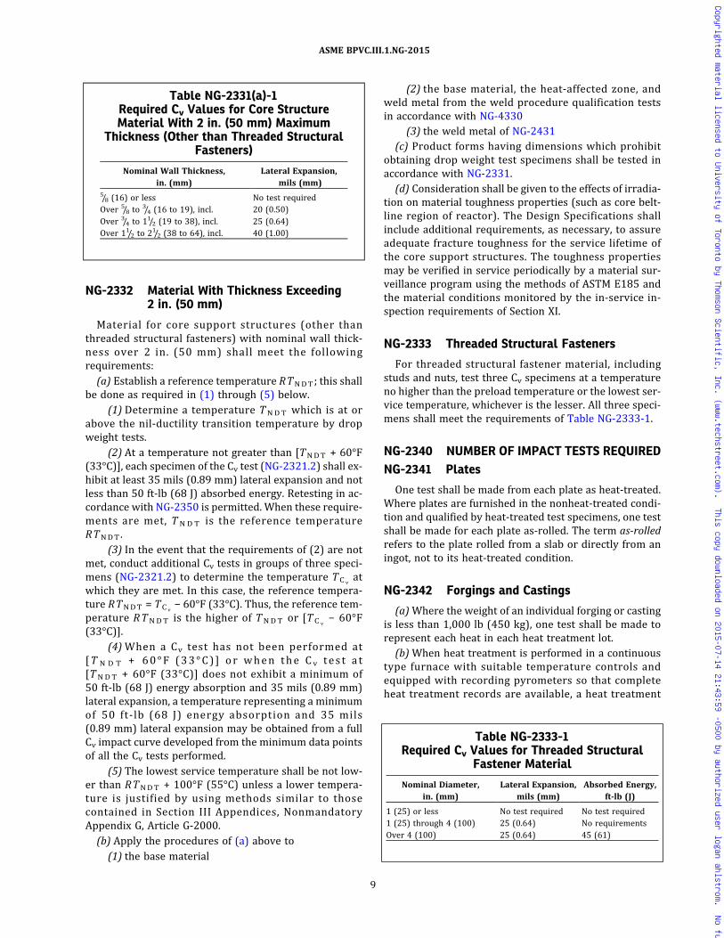
NG-2332 Material With Thickness Exceeding2 in. (50 mm)
Material for core support structures (other thanthreaded structural fasteners) with nominal wall thick-ness over 2 in. (50 mm) shall meet the followingrequirements:
(a) Establish a reference temperature RTNDT; this shallbe done as required in (1) through (5) below.
(1) Determine a temperature TNDT which is at orabove the nil‐ductility transition temperature by dropweight tests.
(2) At a temperature not greater than [TNDT + 60°F(33°C)], each specimen of the Cv test (NG-2321.2) shall ex-hibit at least 35 mils (0.89 mm) lateral expansion and notless than 50 ft-lb (68 J) absorbed energy. Retesting in ac-cordance with NG-2350 is permitted. When these require-ments are met, T N D T is the reference temperatureRTNDT.
(3) In the event that the requirements of (2) are notmet, conduct additional Cv tests in groups of three speci-mens (NG-2321.2) to determine the temperature TC v
atwhich they are met. In this case, the reference tempera-ture RTNDT = TC v
− 60°F (33°C). Thus, the reference tem-perature RTNDT is the higher of TNDT or [TC v
− 60°F(33°C)].
(4)When a Cv test has not been performed at[T N D T + 60°F (33°C) ] or when the Cv tes t a t[TNDT + 60°F (33°C)] does not exhibit a minimum of50 ft-lb (68 J) energy absorption and 35 mils (0.89 mm)lateral expansion, a temperature representing a minimumof 50 ft-lb (68 J) energy absorption and 35 mils(0.89 mm) lateral expansion may be obtained from a fullCv impact curve developed from the minimum data pointsof all the Cv tests performed.
(5) The lowest service temperature shall be not low-er than RTNDT + 100°F (55°C) unless a lower tempera-ture is justified by using methods similar to thosecontained in Section III Appendices, NonmandatoryAppendix G, Article G-2000.
(b) Apply the procedures of (a) above to(1) the base material
(2) the base material, the heat‐affected zone, andweld metal from the weld procedure qualification testsin accordance with NG-4330
(3) the weld metal of NG-2431(c) Product forms having dimensions which prohibit
obtaining drop weight test specimens shall be tested inaccordance with NG-2331.
(d) Consideration shall be given to the effects of irradia-tion on material toughness properties (such as core belt-line region of reactor). The Design Specifications shallinclude additional requirements, as necessary, to assureadequate fracture toughness for the service lifetime ofthe core support structures. The toughness propertiesmay be verified in service periodically by a material sur-veillance program using the methods of ASTM E185 andthe material conditions monitored by the in‐service in-spection requirements of Section XI.
NG-2333 Threaded Structural Fasteners
For threaded structural fastener material, includingstuds and nuts, test three Cv specimens at a temperatureno higher than the preload temperature or the lowest ser-vice temperature, whichever is the lesser. All three speci-mens shall meet the requirements of Table NG-2333-1.
NG-2340 NUMBER OF IMPACT TESTS REQUIREDNG-2341 Plates
One test shall be made from each plate as heat-treated.Where plates are furnished in the nonheat‐treated condi-tion and qualified by heat-treated test specimens, one testshall be made for each plate as‐rolled. The term as‐rolledrefers to the plate rolled from a slab or directly from aningot, not to its heat-treated condition.
NG-2342 Forgings and Castings
(a)Where the weight of an individual forging or castingis less than 1,000 lb (450 kg), one test shall be made torepresent each heat in each heat treatment lot.
(b)When heat treatment is performed in a continuoustype furnace with suitable temperature controls andequipped with recording pyrometers so that completeheat treatment records are available, a heat treatment
Table NG-2331(a)-1Required Cv Values for Core StructureMaterial With 2 in. (50 mm) Maximum
Thickness (Other than Threaded StructuralFasteners)
Nominal Wall Thickness,in. (mm)
Lateral Expansion,mils (mm)
5/8 (16) or less No test requiredOver 5/8 to
3/4 (16 to 19), incl. 20 (0.50)Over 3/4 to 11/2 (19 to 38), incl. 25 (0.64)Over 11/2 to 21/2 (38 to 64), incl. 40 (1.00)
Table NG-2333-1Required Cv Values for Threaded Structural
Fastener Material
Nominal Diameter,in. (mm)
Lateral Expansion,mils (mm)
Absorbed Energy,ft-lb (J)
1 (25) or less No test required No test required1 (25) through 4 (100) 25 (0.64) No requirementsOver 4 (100) 25 (0.64) 45 (61)
9
ASME BPVC.III.1.NG-2015
Copyrighted material licensed to University of Toronto by Thomson Scientific, Inc. (www.techstreet.com). This copy downloaded on 2015-07-14 21:43:59 -0500 by authorized user logan ahlstrom. No further reproduction or distribution is permitted.

charge shall be considered as the lesser of a continuousrun not exceeding 8 hr duration or a total weight, so treat-ed, not exceeding 2,000 lb (900 kg).(c) One test shall be made for each forging or casting of
1,000 lb to 10,000 lb (450 kg to 4 500 kg) in weight.(d) As an alternative to (c) above, a separate test for-
ging or casting may be used to represent forgings or cast-ings of different sizes in one heat and heat treat lot,provided the test piece is a representation of the greatestthickness in the heat treat lot. In addition, test forgingsshall have been subjected to substantially the same reduc-tion and working as the forgings represented.(e) Forgings or castings larger than 10,000 lb
(4 500 kg) shall have two tests per part for CharpyV‐notch and one test for drop weights. The location ofdrop weight or Cv impact test specimens shall be selectedso that an equal number of specimens is obtained frompositions in the forging or casting 180 deg apart.(f) As an alternative to (e) for static castings, a sepa-
rately cast test coupon (NG-2226.3) may be used; one testshall be made for Charpy V‐notch and one test for dropweight.
NG-2343 BarsOne test shall be made for each diameter or size having
a nominal cross‐sectional area greater than 1 in.2 in eachlot, where a lot is defined as one heat of material heat-treated in one charge or as one continuous operation,not to exceed 6,000 lb (2 700 kg).
NG-2344 Tubular Products and FittingsOn products which are seamless or welded without fil-
ler metal, one test shall be made from each lot. On pro-ducts which are welded with filler metal, one additionaltest with the specimens taken from the weld area shallalso be made on each lot. A lot shall be defined as statedin the applicable material specification but in no case shalla lot consist of products from more than one heat of ma-terial and of more than one diameter, with the nominalthickness of any product included not exceeding that tobe impact tested by more than 1/4 in. (6 mm); such a lotshall be in a single heat treatment load or in the same con-tinuous run in a continuous furnace controlled within a50°F (28°C) range and equipped with recordingpyrometers.
NG-2345 Threaded Structural Fastener MaterialOne test shall be made for each lot of material where a
lot is defined as one heat of material heat-treated in onecharge or as one continuous operation, not to exceed inweight the following:
Diameter Weight
13/4 in. (45 mm) and less 1,500 lb (700 kg)
Over 13/4 in. to 21/2 in. (45 mm to 64 mm) 3,000 lb (1 350 kg)
Over 21/2 in. to 5 in. (64 mm to 125 mm) 6,000 lb (2 700 kg)
Over 5 in. (125 mm) 10,000 lb (4 500 kg)
NG-2346 Test DefinitionUnless otherwise stated in NG-2341 through NG-2345,
the term one test is defined to include the combination ofthe drop weight test and the Cv test when RTNDT is re-quired (NG-2332) and only the Cv test when determina-tion of RTNDT is not required (NG-2331).
NG-2350 RETESTS(a) For Cv tests required by NG-2330, one retest at the
same temperature may be conducted, provided(1) the average value of the test results meets the
minimum requirements(2) not more than one specimen per test is below the
minimum requirements(3) the specimen not meeting the minimum require-
ments is not lower than 10 ft-lb (13.6 J) or 5 mils(0.13 mm) below the specified requirements(b) A retest consists of two additional specimens taken
as near as practicable to the failed specimens. For accep-tance of the retest, both specimens shall meet the mini-mum requirements.
NG-2360 CALIBRATION OF INSTRUMENTS ANDEQUIPMENT
Calibration of temperature instruments and Cv impacttest machines used in impact testing shall be performedat the frequency specified in the following:(a) Temperature instruments used to control test tem-
perature of specimens shall be calibrated and the resultsrecorded to meet the requirements of NCA‐3858.2 at leastonce in each 3‐month interval.(b) Cv test machines shall be calibrated and the results
recorded to meet the requirements of NCA‐3858.2. Thecalibrations shall be performed using the frequency andmethods outlined in ASTM E23 and employing standardspecimens obtained from the National Institute of Stan-dards and Technology, or any supplier of subcontractedcalibration services accredited in accordance with the re-quirements of NCA-3126 and NCA-3855.3(c).
NG-2400 WELDING MATERIAL
NG-2410 GENERAL REQUIREMENTS(a) All welding material used in the construction and
repair of components or material, except welding materi-al used for hard surfacing, shall conform to the require-ments o f the mater ia l spec i f i ca t ion or to therequirements for other welding material as permitted inSection IX. In addition, welding material shall conformto the requirements stated in this subarticle and to therules covering identification in NG-2150.(b) The Certificate Holder shall provide the organiza-
tion performing the testing with the following informa-tion, as applicable:
(1)welding process(2) SFA Specification and classification
10
ASME BPVC.III.1.NG-2015
Copyrighted material licensed to University of Toronto by Thomson Scientific, Inc. (www.techstreet.com). This copy downloaded on 2015-07-14 21:43:59 -0500 by authorized user logan ahlstrom. No further reproduction or distribution is permitted.
ð15Þ
(3) other identification if no SFA Specification applies(4)minimum tensile strength [NG-2431.1(e)] in
either the as‐welded or heat‐treated condition or both[NG-2431.1(c)]
(5) drop weight test for material as‐welded or heat-treated or both (NG-2332)
(6) Charpy V‐notch test for material as‐welded orheat-treated or both (NG-2331); the test temperature,and the lateral expansion or the absorbed energy, shallbe provided
(7) the preheat and interpass temperatures to beused during welding of the test coupon [NG-2431.1(c)]
(8) postweld heat treatment time, temperaturerange, and maximum cooling rate, if the production weldwill be heat-treated [NG-2431.1(c)]
(9) elements for which chemical analysis is requiredper the SFA Specification or WPS, and NG-2432
(10)minimum delta ferrite (NG-2433)
NG-2420 REQUIRED TESTSThe required tests shall be conducted for each lot of
covered, flux cored, or fabricated electrodes; for each heatof bare electrodes, rod, or wire for use with the OFW,GMAW, GTAW, PAW, and EGW (electro‐gas welding) pro-cesses (Section IX, QG-109); for each heat of consumableinserts; for each combination of heat of bare electrodesand lot of submerged arc flux; for each combination oflot of fabricated electrodes and lot of submerged arc flux;for each combination of heat of bare electrodes or lot offabricated electrodes and dry blend of supplementarypowdered filler metal and lot of submerged arc flux; orfor each combination of heat of bare electrodes and lotof electroslag flux. Tests performed on welding materialin the qualification of weld procedures will satisfy thetesting requirements for the lot, heat, or combination ofheat and batch of welding material used, provided thetests required by Article NG-4000 and this subarticleare made and the results conform to the requirementsof this Article. The following definitions apply:
(a) dry batch of covering mixture: the quantity of drycovering ingredients mixed at one time in one mixing ves-sel; a dry batch may be used singly or may be subse-quently subdivided into quantities to which the liquidbinders may be added to produce a number of wet mixes[see (c)].
(b) dry blend: one or more dry batches mixed in a mix-ing vessel and combined proportionately to produce auniformity of mixed ingredients equal to that obtainedby mixing the same total amount of dry ingredients atone time in one mixing vessel.
(c) wet mix: the combination of a dry batch or dry blend[(a) and (b), respectively] and liquid binder ingredients atone time in one mixing vessel.
(d) lot of covered, flux cored, or fabricated electrodes: thequantity of electrodes produced from the same combina-tion of heat of metal and dry batch, dry blend, or chemi-cally controlled mixes of flux or core materials.
Alternatively, a lot of covered, flux cored, or fabricatedelectrodes may be considered one type and size of elec-trode, produced in a continuous period, not to exceed24 hr and not to exceed 100,000 lb (45 000 kg), from che-mically controlled tube, wire, or strip and a dry batch, adry blend, or chemically controlled mixes of flux, pro-vided each container of welding materials is coded foridentification and traceable to the production period,the shift, line, and the analysis range of both the mixand the rod, tube, or strip used to make the electrodes.
(1) chemically controlled tube, wire, or strip: consum-able tube, wire, or strip material supplied on coils with amaximum of one splice per coil that has been chemicallyanalyzed to ensure that the material conforms to the elec-trode manufacturer’s chemical control limits for the spe-cific type of electrode. Both ends of each coil shall bechemically analyzed, except those coils which are splicefree need only be analyzed on one end of the coil.
(2) chemically controlled mixes of flux: flux materialthat has been chemically analyzed to assure that it con-forms to the percent allowable variation from the elec-trode manufacturer ’s standard for each chemicalelement for that type electrode. A chemical analysis shallbe made on each mix made in an individual mixing vesselafter blending.
(e) heat of bare electrode, rod, wire, or consumable in-sert: the material produced from the same melt of metal.
(f) Alternatively, for carbon and low alloy steel bareelectrode, rod, wire, or consumable inserts for use withSAW, OFW, GMAW, GTAW, PAW, and EGW processes, aheatmay be defined as either the material produced fromthe same melt of metal, or the material produced fromone type and size of wire when produced in a continuousperiod, not to exceed 24 hr and not to exceed 100,000 lb(45 000 kg), from chemically controlled wire, subject tothe following requirements:
(1) For the chemical control of the product of the rodmill, coils shall be limited to a maximum of one spliceprior to processing the wire. Chemical analysis shall bemade from a sample taken from both ends of each coilof mill coiled rod furnished by mills permitting splicedcoil practice of one splice maximum per coil. A chemicalanalysis need be taken from only one end of rod coilsfurnished by mills prohibiting spliced coil practice.
(2) Carbon, manganese, silicon, and other intention-ally added elements shall be determined to identify thematerial to ensure that it conforms to the SFA or user’smaterial specification.
(3) Each container of wire shall be coded for identifi-cation and traceability to the lot, production period, shift,line, and analysis of rod used to make the wire.
(g) lot of submerged arc or electroslag flux: the quantityof flux produced from the same combination of raw mate-rials under one production schedule.
(h) dry blend of supplementary powdered filler metal:one or more mixes of material produced in a continuousperiod, not to exceed 24 hr and not to exceed 20,000 lb
11
ASME BPVC.III.1.NG-2015
Copyrighted material licensed to University of Toronto by Thomson Scientific, Inc. (www.techstreet.com). This copy downloaded on 2015-07-14 21:43:59 -0500 by authorized user logan ahlstrom. No further reproduction or distribution is permitted.

(9 000 kg), from chemically controlled mixes of powderedfiller metal, provided each container of powdered metal iscoded for identification and traceable to the productionperiod, the shift, and the mixing vessel.(i) chemically controlled mix of powdered filler metal:
powdered filler metal material that has been chemicallyanalyzed to ensure that it conforms to the percent allow-able variation from the powdered filler metal manufac-turer’s standard, for each chemical element, for thattype of powdered filler metal. A chemical analysis shallbe made on each mix made in an individual mixing vesselafter blending. The chemical analysis range of the supple-mental powdered filler shall be the same as that of thewelding electrode, and the ratio of powder to electrodeused to make the test coupon shall be the maximum per-mitted for production welding.
NG-2430 WELD METAL TESTSNG-2431 Mechanical Properties Test
Tensile and impact tests shall be made, in accordancewith this paragraph, of welding material used to joinP‐Nos. 1, 3 through 7, 9, and 11 base materials in any com-bination, with the following exceptions:(a) austenitic stainless steel and nonferrous welding
material used to join the listed P‐Numbers(b) consumable inserts (backing filler material)(c) welding material used for GTAW root deposits with
a maximum of two layers(d) welding material to be used for the welding of base
material exempted from impact testing by NG-2300 shalllikewise be exempted from the impact testing required bythis paragraph
NG-2431.1 General Test Requirements. The weldingtest coupon shall be made in accordance with (a) through(f) below using each process with which the weld materi-al will be used in production welding.(a) Test coupons shall be of sufficient size and thick-
ness such that the test specimens required herein canbe removed.(b) The weld metal to be tested for all processes except
electroslag welding shall be deposited in such a manneras to eliminate substantially the influence of the base ma-terial on the results of the tests. Weld metal to be usedwith the electroslag process shall be deposited in such amanner as to conform to one of the applicable WeldingProcedure Specifications (WPS) for production welding.The base material shall conform with the requirementsof Section IX, QW‐403.1 or QW‐403.4, as applicable.(c) The welding of the test coupon shall be performed
within the range of preheat and interpass temperatureswhich will be used in production welding. Coupons shallbe tested in the as‐welded condition or they shall betested in the applicable postweld heat-treated conditionwhen the production welds are to be postweld heat-treated. The postweld heat treatment holding time4 shallbe at least 80% of the maximum time to be applied to the
weld metal in production application. The total time forpostweld heat treatment of the test coupon may be ap-plied in one heating cycle. The cooling rate from the post-weld heat treatment temperature shall be of the sameorder as that applicable to the weld metal in the compo-nent. In addition, weld coupons for weld metal to be usedwith the electroslag process that are tested in the as‐welded condition, or following a postweld heat treatmentwithin the holding temperature ranges of TableNG-4622.1-1 or Table NG-4622.4(c)-1, shall have a thick-ness within the range of 0.5 to 1.1 times the thickness ofthe welds to be made in production. Electroslag weld cou-pons to be tested following a postweld heat treatmentwhich will include heating the coupon to a temperatureabove the “Holding Temperature Range” of TableNG-4622.1-1 for the type of material being tested shallhave a thickness within the range of 0.9 to 1.1 times thethickness of the welds to be made in production.
(d) The tensile specimens, and the Cv impact specimenswhere required, shall be located and prepared in accor-dance with the requirements of SFA‐5.1, or the applicableSFA Specification. Drop weight impact test specimens,where required, shall be oriented so that the longitudinalaxis is transverse to the weld with the notch in the weldface or in a plane parallel to the weld face. For impact spe-cimen preparation and testing, the applicable parts ofNG-2321.1 and NG-2321.2 shall apply. The longitudinalaxis of the specimen shall be at a minimum depth of 1/4tfrom a surface, where t is the thickness of the test weld.
(e) One all weld metal tensile specimen shall be testedand shall meet the specified minimum tensile strength re-quirements of the base material specification. When basematerials of different specifications are to be welded, thetensile strength requirements shall conform to the speci-fied minimum tensile strength requirements of either ofthe base material specifications.
(f) Impact specimens of the weld metal shall be testedwhere impact tests are required for either of the base ma-terials of the production weld. The weld metal shall con-form to the requirements of NG-2330 applicable to thebase material. Where different requirements exist forthe two base materials, the weld metal may conform toeither of the two requirements.
NG-2431.2 Standard Test Requirements. In lieu ofthe use of the General Test Requirements specified inNG-2431.1, tensile and impact tests may be made in ac-cordance with this subparagraph where they are requiredfor mild and low alloy steel covered electrodes. The mate-rial combinations to require weld material testing, aslisted in NG-2431, shall apply for this Standard Test Re-quirements option. The limitations and testing under thisStandard Test option shall be in accordance with thefollowing:
(a) Testing to the requirements of this subparagraphshall be limited to electrode classifications included inSpecification SFA‐5.1 or SFA‐5.5.
12
ASME BPVC.III.1.NG-2015
Copyrighted material licensed to University of Toronto by Thomson Scientific, Inc. (www.techstreet.com). This copy downloaded on 2015-07-14 21:43:59 -0500 by authorized user logan ahlstrom. No further reproduction or distribution is permitted.

ð15Þ
(b) The test assembly required by SFA‐5.1 or SFA‐5.5,as applicable, shall be used for test coupon preparation,except that it shall be increased in size to obtain the num-ber of Cv specimens and the drop weight test specimensrequired by NG-2330, where applicable.
(c) The welding of the test coupon shall conform to therequirements of the SFA Specification for the classifica-tion of electrode being tested. Coupons shall be testedin the as‐welded condition and also in the postweld heat-treated condition. The postweld heat treatment tempera-tures shall be in accordance with Table NG-4622.1-1 forthe applicable P‐Number equivalent. The time at post-weld heat treatment temperature shall be 8 hr (this qua-lifies postweld heat treatments of 10 hr or less). Wherethe postweld heat treatment of the production weld ex-ceeds 10 hr or the PWHT temperature is other than thatrequired above, the general test of NG-2431.1 shall beused.
(d) The tensile and Cv specimens shall be located andprepared in accordance with the requirements ofSFA‐5.1 or SFA‐5.5, as applicable. Drop weight impact testspecimens, where required, shall be located and orientedas specified in NG-2431.1(d).
(e) One all weld metal tensile specimen shall be testedand shall meet the specified minimum tensile strength re-quirement of the SFA Specification for the applicable elec-trode classification.
(f) The requirements of NG-2431.1(f) shall be applic-able to the impact testing of this option.
NG-2432 Chemical Analysis Test
Chemical analysis of filler metal or weld deposits shallbe made in accordance with NG-2420 and as required bythe following subparagraphs.
NG-2432.1 Test Method. The chemical analysis testshall be performed in accordance with this subparagraphand Table NG-2432.1-1, and the results shall conform toNG-2432.2.
(a) A‐No. 8 welding material to be used with GTAW andPAW processes and any other welding material to be usedwith any GTAW, PAW, or GMAW process shall have
chemical analysis performed either on the filler metal oron a weld deposit made with the filler metal in accor-dance with (c) or (d) below.
(b) A‐No. 8 welding material to be used with other thanthe GTAW and PAW processes and other welding materialto be used with other than the GTAW, PAW, or GMAWprocess shall have chemical analysis performed on a welddeposit of the material or combination of materials beingcertified in accordance with (c) or (d) below. The removalof chemical analysis samples shall be from an undilutedweld deposit made in accordance with (c) below. As an al-ternative, the deposit shall be made in accordance with(d) below for material that will be used for corrosion re-sistant overlay cladding. Where the Welding ProcedureSpecification or the welding material specification speci-fies percentage composition limits for analysis, it shallstate that the specified limits apply for either the fillermetal analysis or the undiluted weld deposit analysis orfor in situ cladding deposit analysis in conformance withthe above required certification testing.
(c) The preparation of samples for chemical analysis ofundiluted weld deposits shall comply with the method gi-ven in the applicable SFA Specification. Where a weld de-posit method is not provided by the SFA Specification, thesample shall be removed from a weld pad, groove, orother test weld9 made using the welding process that willbe followed when the welding material or combination ofwelding materials being certified is consumed. The weldfor A‐No. 8 material to be used with the GMAW or EGWprocess shall be made using the shielding gas compositionspecified in the Welding Procedure Specifications thatwill be followed when the material is consumed. The testsample for ESW shall be removed from the weld metal ofthe Mechanical Properties Test coupon. Where a chemicalanalysis is required for a welding material which does nothave a Mechanical Properties Test requirement, a chemi-cal analysis test coupon shall be prepared as required byNG-2431.1(c), except that heat treatment of the coupon isnot required and the weld coupon thickness require-ments of NG-2431.1(c) do not apply.
(d) The alternative method provided in (b) above forthe preparation of samples for chemical analysis of weld-ing material to be used for corrosion‐resistant overlaycladding shall require a test weld made in accordancewith the essential variables of the Welding ProcedureSpecification that will be followed when the welding ma-terial is consumed. The test weld shall be made in confor-mance with the requirements of Section IX, QW‐214.1.The removal of chemical analysis samples shall conformwith QW‐453 for the minimum thickness for which theWelding Procedure Specification is qualified.
NG-2432.2 Requirements for Chemical Analysis.The chemical elements to be determined, the compositionrequirements of the weld metal, and the recording of re-sults of the chemical analysis shall be in accordance withthe following:
Table NG-2432.1-1Sampling of Welding Materials for Chemical
Analysis
GTAW/PAW GMAWAll OtherProcesses
A‐No. 8 filler metal Filler metalor welddeposit
Welddeposit
Welddeposit
All other filler metal Filler metalor welddeposit
Filler metalor welddeposit
Welddeposit
13
ASME BPVC.III.1.NG-2015
Copyrighted material licensed to University of Toronto by Thomson Scientific, Inc. (www.techstreet.com). This copy downloaded on 2015-07-14 21:43:59 -0500 by authorized user logan ahlstrom. No further reproduction or distribution is permitted.

(a) All welding material shall be analyzed for the ele-ments listed in Table NG-2432.2-1 and for other elementsspecified either in the welding material specification re-ferenced by the Welding Procedure Specification or inthe Welding Procedure Specification.
(b) The chemical composition of the weld metal or fillermetal shall conform to the welding material specificationfor elements having specified percentage compositionlimits. Where the Welding Procedure Specification con-tains a modification of the composition limits of SFA orother referenced welding material specifications, or pro-vides limits for additional elements, these compositionlimits of the Welding Procedure Specification shall applyfor acceptability.
(c) The results of the chemical analysis shall be re-ported in accordance with NCA‐3862.1. Elements listedin Table NG-2432.2-1 but not specified in the welding ma-terial specification shall be reported for information only.
NG-2433 Delta Ferrite Determination
A determination of delta ferrite shall be performed onA‐No. 8 weld material (Section IX, Table QW-442) backingfiller metal (consumable inserts); bare electrode, rod, orwire filler metal; or weld metal, except that delta ferritedeterminations are not required for SFA‐5.4, Type 16‐8‐2, or A‐No. 8 weld filler metal to be used for weld metalcladding.
NG-2433.1 Method. Delta ferrite determinations ofwelding material, including consumable insert material,shall be made using a magnetic measuring instrumentand weld deposits made in accordance with (b) below. Al-ternatively, the delta ferrite determinations for weldingmaterials may be performed by the use of chemical analy-sis of NG-2432 in conjunction with Figure NG-2433.1-1.
(a) Calibration of magnetic instruments shall conformto AWS A4.2.
(b) The weld deposit for magnetic delta ferrite determi-nation shall be made in accordance with NG-2432.1(c).
(c) A minimum of six ferrite readings shall be taken onthe surface of the weld deposit. The readings obtainedshall be averaged to a single Ferrite Number (FN).
NG-2433.2 Acceptance Standards. The minimum ac-ceptable delta ferrite shall be 5FN. The results of the deltaferrite determination shall be included in the CertifiedMaterial Test Report of NG-2130 or NG-4120.
NG-2440 STORAGE AND HANDLING OFWELDING MATERIAL
Suitable storage and handling of electrodes, flux, andother welding material shall be maintained. Precautionsshall be taken to minimize absorption of moisture byfluxes and cored, fabricated, and coated electrodes.
NG-2500 EXAMINATION AND REPAIR OFCORE SUPPORT STRUCTUREMATERIAL
NG-2510 EXAMINATION OF CORE SUPPORTSTRUCTURE MATERIAL
Material for core support structures shall be examinedby nondestructive methods applicable to the material andproduct form as required by the rules of this subarticle.
NG-2520 EXAMINATION AFTER QUENCHINGAND TEMPERING
Ferritic steel products that have their properties en-hanced by quenching and tempering shall be examinedby the methods specified in this subarticle for each pro-duct form after the quenching and tempering phase ofthe heat treatment.
NG-2530 EXAMINATION AND REPAIR OF PLATENG-2531 Required Examination
All plates for core support structures greater than 3/4 in.(19 mm) thickness shall be examined by the straightbeam ultrasonic method in accordance with NG-2532.1.
NG-2532 Examination ProceduresNG-2532.1 Straight Beam Examination. The re-
quirements for straight beam examination shall be in ac-cordance with SA-578, as shown in Section V, except thatthe extent of examination and the acceptance standardsto be applied are given in the following:(a) Extent of Examination. 100% of one major plate sur-
face shall be covered by moving the search unit in parallelpaths with not less than a 10% overlap.(b) Acceptance Standards
(1) Any area where one or more imperfections pro-duce a continuous total loss of back reflection accompa-nied by continuous indications on the same plane thatcannot be encompassed within a circle whose diameteris 3 in. (75 mm) or one‐half of the plate thickness, which-ever is greater, is unacceptable.
(2) In addition, two or more imperfections smallerthan described in (1) above shall be unacceptable unlessseparated by a minimum distance equal to the greatest
Table NG-2432.2-1Welding Material Chemical Analysis
Materials Elements
Carbon and low alloymaterials
C, Cr, Mo, Ni, Mn, Si, P, S, V, Cu
Chromium and Cr‐Nistainless material
C, Cr, Mo, Ni, Mn, Si, P, S, V, Cb + Ta, Ti, Cu
Nickel and Ni‐alloymaterials
C, Cr, Mo, Ni, Mn, Si, S, Cb + Ta, Cu, Fe, Co
14
ASME BPVC.III.1.NG-2015
Copyrighted material licensed to University of Toronto by Thomson Scientific, Inc. (www.techstreet.com). This copy downloaded on 2015-07-14 21:43:59 -0500 by authorized user logan ahlstrom. No further reproduction or distribution is permitted.

diameter of the larger imperfection, or unless they may becollectively encompassed by the circle described in (1)above.
NG-2532.2 Angle Beam Examination. The require-ments for angle beam examination shall be in accordancewith SA-577, Specification for Ultrasonic Shear Wave In-spection of Steel Plates, as shown in Section V, as supple-mented by this subparagraph. The calibration notch,extent of examination, and the acceptance standards tobe applied are given in the following:
(a) Calibration. Angle beam examination shall be cali-brated from a notch.
(b) Extent of Examination. 100% of one major plate sur-face shall be covered by moving the search unit in parallelpaths with not less than 10% overlap.
(c) Acceptance Standards. Material which shows one ormore imperfections which produce indications exceedingin amplitude the indication from the calibration notch isunacceptable.
NG-2537 Time of ExaminationAcceptance examinations shall be performed at the
time of manufacture as required in the following:(a) Ultrasonic examination shall be performed after
rolling to size and after heat treatment, except postweldheat treatment.
(b) Radiographic examination of repair welds, when re-quired, may be performed prior to any required postweldheat treatment.
(c) Magnetic particle or liquid penetrant examination ofrepair welds in ferritic material shall be performed afterfinal heat treatment, except that the examination maybe performed prior to postweld heat treatment of P‐No.1 material 2 in. (50 mm) and less nominal thickness. Allrepair welds in austenitic and nonferrous material maybe liquid penetrant examined prior to any required post-weld heat treatment.
Figure NG-2433.1-1Weld Metal Delta Ferrite Content
18
10
12
14
16
18
10
12
14
16
18
20 22 24
Creq � Cr � Mo � 0.7 Nb
Ni e
q �
Ni �
35
C �
20
N �
0.2
5 C
u
26 28 30
18 20
Ferr
ite n
umbe
r (FN
)0
22 24 26 28 30
2
4
6
8
12
16
18
14
10
20
24
22
26
28
30
35
40
45
50
70
80
90
100
55
65
75
85
95
60
GENERAL NOTES:(a) The actual nitrogen content is preferred. If this is not available, the following applicable nitrogen value shall be used:
(1) GMAW welds, 0.08%, except that when self‐shielding, flux‐cored electrodes are used, 0.12%(2) Welds made using other processes, 0.06%.
(b) This diagram is identical to the WRC‐1992 Diagram, except that the solidification mode lines have been removed for ease of use.
15
ASME BPVC.III.1.NG-2015
Copyrighted material licensed to University of Toronto by Thomson Scientific, Inc. (www.techstreet.com). This copy downloaded on 2015-07-14 21:43:59 -0500 by authorized user logan ahlstrom. No further reproduction or distribution is permitted.

NG-2538 Elimination of Surface Defects
Surface defects shall be removed by grinding or ma-chining, provided the following requirements are met:(a) The depression, after defect elimination, is blended
uniformly into the surrounding surface with not less thana 3:1 taper.(b) After defect elimination, the area is examined by the
magnetic particle method in accordance with NG-2545 orthe liquid penetrant method in accordance with NG-2546to assure that the defect has been removed or reduced toan imperfection of an acceptable size.(c) Areas ground to remove oxide scale or other me-
chanically caused impressions for appearance or to facil-itate proper ultrasonic testing need not be examined bythe magnetic particle or liquid penetrant test method.(d) If the elimination of the defect reduces the thickness
of the section below the minimum required to satisfy therules of Article NG-3000, the product shall be repaired inaccordance with NG-2539.
NG-2539 Repair by Welding
Material from which defects have been removed maybe repaired by welding, provided the requirements ofthe following subparagraphs are met. Prior approval ofthe Certificate Holder shall be obtained for any repair ofplates to be used in the manufacture of core supportstructures.
NG-2539.1 Defect Removal. The defect shall be re-moved or reduced to an imperfection of an acceptablesize by suitable mechanical or thermal cutting or gougingmethods and the cavity prepared for repair (NG-4211.1).
NG-2539.2 Qualification of Welding Procedures andWelders. The welding procedure and welders or weldingoperators shall be qualified in accordance with ArticleNG-4000 and Section IX.
NG-2539.3 Blending of Repaired Areas. After repair,the surface shall be blended uniformly into the surround-ing surface.
NG-2539.4 Examination of Repair Welds. Each re-pair weld shall be examined by the magnetic particlemethod (NG-2545) or by the liquid penetrant method(NG-2546). In addition, when the depth of the repair cav-ity exceeds the lesser of 3/8 in. (10 mm) or 10% of the sec-tion thickness, the repair weld shall be radiographed inaccordance with Article NG-5000 and to the acceptancestandards of NG-5320 or shall be ultrasonically examinedafter repair in accordance with NG-2532.2 or NG-2532.1.
NG-2539.5 Heat Treatment After Repairs. The pro-duct shall be heat-treated after repair in accordance withthe heat treatment requirements of NG-4620.
NG-2539.6 Material Report Describing Defects andRepairs. Each defect repair exceeding in depth the lesserof 3/8 in. (10 mm) or 10% of the section thickness and, inaddition, all repair welds exceeding an accumulated area
of 20% of the area of the part or 15 in.2 (9 700 mm2),whichever is less, shall be described in the Certified Mate-rial Test Report. The Certified Material Test Report foreach piece shall include a chart which shows the locationand size of the prepared cavity, the welding material iden-tification, the welding procedure, the heat treatment, andthe examination results, including radiographs.
NG-2540 EXAMINATION AND REPAIR OFFORGINGS AND BARS
NG-2541 Required Examinations
(a) Forgings and bars except as noted in NG-2551 shallbe examined by the ultrasonic method in accordance withNG-2542, except that forgings or sections of forgingswhich have coarse grains or configurations which donot yield meaningful examination results by ultrasonicmethods shall be examined by radiographic methods inaccordance with Section V, Article 2, and the acceptancestandards of NG-5320. In addition, selected surfaces, asdesignated by the Certificate Holder, shall be liquid pene-trant examined in accordance with NG-2546 or magneticparticle examined in accordance with NG-2545.(b) Forged flanges and fittings, such as elbows, tees,
and couplings, shall be examined in accordance with therequirements of NG-2550.(c) Bar material used for threaded structural fasteners
shall be examined in accordance with NG-2580.
NG-2542 Ultrasonic ExaminationNG-2542.1 Examination Procedure. All forgings in
the rough forged or finished condition, and bars, shallbe examined in accordance with one of the following spe-cifications: SA-745, Standard Practice for Ultrasonic Ex-amination of Austenitic Steel Forgings; or SA-388,Recommended Practice for Ultrasonic Testing and Inspec-tion of Heavy Steel Forgings, as shown in Section V, Article23. Contact, immersion, or water column coupling is per-missible. The following techniques are required, asapplicable:(a) All forgings and bars shall be examined by the ultra-
sonic method using the straight beam technique.(b) Ring forgings and other hollow forgings shall, in ad-
dition, be examined using the angle beam technique intwo circumferential directions, unless wall thickness orgeometric configuration makes angle beam examinationimpractical.(c) Forgings may be examined by the use of alternative
ultrasonic methods which utilize distance amplitude cor-rections provided the acceptance standards are shown tobe equivalent to those listed in NG-2542.2.
NG-2542.2 Acceptance Standards.(a) Straight Beam General Rule. A forging shall be unac-
ceptable if the results of straight beam examinationsshow one or more reflectors which produce indicationsaccompanied by a complete loss of back reflection not as-sociated with or attributable to geometric configurations.
16
ASME BPVC.III.1.NG-2015
Copyrighted material licensed to University of Toronto by Thomson Scientific, Inc. (www.techstreet.com). This copy downloaded on 2015-07-14 21:43:59 -0500 by authorized user logan ahlstrom. No further reproduction or distribution is permitted.

Complete loss of back reflection is assumed when theback reflection falls below 5% of full calibration screenheight.
(b) Angle Beam Rule. A forging shall be unacceptable ifthe results of angle beam examinations show one or morereflectors which produce indications exceeding in ampli-tude the indication from the appropriate calibrationnotches.
NG-2545 Magnetic Particle ExaminationNG-2545.1 Examination Procedure. The procedure
for magnetic particle examination shall be in accordancewith the methods of Section V, Article 7.
NG-2545.2 Evaluation of Indications.(a)Mechanical discontinuities at the surface are re-
vealed by the retention of the examination medium. All in-dications are not necessarily defects, however, sincecertain metallurgical discontinuities and magnetic perme-ability variations may produce similar indications whichare not relevant.
(b) Any indication in excess of the NG-2545.3 accep-tance standards which is believed to be nonrelevant shallbe reexamined by the same or other nondestructive ex-amination methods to verify whether or not actual de-fects are present. Surface conditioning may precede thereexamination. Nonrelevant indications which wouldmask defects are unacceptable.
(c) Relevant indications are indications which resultfrom imperfections. Linear indications are indications inwhich the length is more than three times the width.Rounded indications are indications which are circularor elliptical with the length equal to or less than threetimes the width.
NG-2545.3 Acceptance Standards.(a) Only imperfections producing indications with ma-
jor dimensions greater than 1/16 in. (1.5 mm) shall be con-sidered relevant imperfections.
(b) Imperfections producing the following relevant in-dications are unacceptable:
(1) any linear indications greater than 1/16 in.(1.5 mm) long for material less than 5/8 in. (16 mm) thick,greater than 1/8 in. (3 mm) long for material from 5/8 in.(16 mm) thick to under 2 in. (50 mm) thick, and 3/16 in.(5 mm) long for material 2 in. (50 mm) thick and greater
(2) rounded indications with dimensions greaterthan 1/8 in. (3 mm) for thicknesses less than 5/8 in.(16 mm) and greater than 3/16 in. (5 mm) for thicknesses5/8 in. (16 mm) and greater
(3) four or more relevant indications in a line sepa-rated by 1/16 in. (1.5 mm) or less edge to edge
(4) ten or more relevant indications in any 6 in.2
(4 000 mm2) of area whose major dimension is no morethan 6 in. (150 mm) with the dimensions taken in themost unfavorable location relative to the indicationsbeing evaluated
NG-2546 Liquid Penetrant ExaminationNG-2546.1 Examination Procedure. The procedure
for liquid penetrant examination shall be in accordancewith the methods of Section V, Article 6.
NG-2546.2 Evaluation of Indications.(a)Mechanical discontinuities at the surface are re-
vealed by bleeding out of the penetrant; however, loca-lized surface discontinuities such as may occur frommachining marks or surface conditions may produce sim-ilar indications which are not relevant.
(b) Any indication in excess of the NG-2546.3 accep-tance standards that is believed to be nonrelevant shallbe reexamined to verify whether or not actual defectsare present. Surface conditioning may precede the reexa-mination. Nonrelevant indications and broad areas of pig-mentation which would mask defects are unacceptable.
(c) Relevant indications are indications which resultfrom imperfections. Linear indications are indications inwhich the length is more than three times the width.Rounded indications are indications which are circularor elliptical with the length equal to or less than threetimes the width.
NG-2546.3 Acceptance Standards.(a) Only imperfections producing indications with ma-
jor dimensions greater than 1/16 in. (1.5 mm) shall be con-sidered relevant imperfections.
(b) Imperfections producing the following relevant in-dications are unacceptable:
(1) any linear indications greater than 1/16 in.(1.5 mm) long for material less than 5/8 in. (16 mm) thick,greater than 1/8 in. (3 mm) long for material from 5/8 in.(16 mm) thick to under 2 in. (50 mm) thick, and 3/16 in.(5 mm) long for materials 2 in. (50 mm) thick and greater
(2) rounded indications with dimensions greaterthan 1/8 in. (3 mm) for thicknesses less than 5/8 in.(16 mm) and greater than 3/16 in. (5 mm) for thicknesses5/8 in. (16 mm) and greater
(3) four or more relevant indications in a line sepa-rated by 1/16 in. (1.6 mm) or less edge to edge
(4) ten or more relevant indications in any 6 in.2
(4 000 mm2) of area whose major dimension is no morethan 6 in. (150 mm) with the dimensions taken in themost unfavorable location relative to the indicationsbeing evaluated
NG-2547 Time of ExaminationAcceptance examinations, including those for repair
welds, shall be performed at the time of manufacture asrequired in the following:
(a) Ultrasonic examination may be performed at anytime after forging, and the maximum practical volumeshall be examined after final heat treatment, excludingpostweld heat treatment.
(b) Radiographic examination of repair welds, if re-quired, may be performed prior to any required postweldheat treatment.
17
ASME BPVC.III.1.NG-2015
Copyrighted material licensed to University of Toronto by Thomson Scientific, Inc. (www.techstreet.com). This copy downloaded on 2015-07-14 21:43:59 -0500 by authorized user logan ahlstrom. No further reproduction or distribution is permitted.

NG-2548 Elimination of Surface Defects
Elimination of surface defects shall be made in accor-dance with NG-2538.
NG-2549 Repair by Welding
Repair by welding shall be in accordance withNG-2539, except that(a) the depth of repair that is permitted is not limited,
and(b) for ferritic steel forgings, the completed repair may
be examined by the ultrasonic methods in accordancewith the requirements of NG-2542 in lieu of radiography.
NG-2550 EXAMINATION AND REPAIR OFSEAMLESS AND WELDED TUBULARPRODUCTS AND FITTINGS
NG-2551 Required Examination
(a) The examination performed shall be practical andyield meaningful pertinent information for the productform being examined. Certain examination methods areineffective for some material conditions and product con-figuration. Some examples are
(1) it may not be practical or meaningful to examineirregular shapes such as welding flanges and fittings byultrasonic methods
(2) ultrasonic examination employing special techni-ques is required on coarse‐grained austenitic stainlesssteel or coarse‐grained, nickel‐base alloy materials(b)Welded tubular products and fittings, including
flanges and fittings, made from plate material greaterthan 3/4 in. (19 mm) in thickness shall be ultrasonicallyor radiographically examined in accordance withNG-2552 or NG-2553.(c) All welds in welded tubular products and fittings,
including flanges and fittings, shall be ultrasonically orradiographically examined in accordance with NG-2552or NG-2553. In addition, all welds shall be magnetic par-ticle or liquid penetrant examined on all accessible sur-faces in accordance with NG-2555 or NG-2556.(d)Wrought seamless tubular products and fittings, in-
cluding flanges and fittings machined from forgings andbars, greater than 3/8 in. (10 mm) thickness shall be ultra-sonically or radiographically examined in accordancewith NG-2552 or NG-2553.
NG-2552 Ultrasonic ExaminationNG-2552.1 Examination Procedure. The procedure
for ultrasonic examination shall provide a sensitivitywhich will consistently detect defects that produce indica-tions equal to and greater than the indication producedby standard defects included in the reference specimenspecified in NG-2552.2. Products with defects that pro-duce indications in excess of the indications producedby the standard defects in the reference specimens are
unacceptable unless the defects are eliminated or re-paired in accordance with NG-2558 or NG-2559, asapplicable.
NG-2552.2 Reference Specimens.(a) The reference specimen shall be of the same nom-
inal diameter and thickness and of the same nominal com-position and heat-treated condition as the product whichis being examined. The standard defects shall be axialnotches or grooves on the outside and the inside surfacesof the reference specimen and shall have a length of ap-proximately 1 in. (25 mm) or less, a width not to exceed1/16 in. (1.5 mm), and a depth not greater than the largerof 0.004 in. (0.10 mm) or 5% of the nominal wall thick-ness. The reference specimen may be the product beingexamined.(b) The reference specimen shall be long enough to si-
mulate the handling of the product being examinedthrough the examination equipment. When more thanone standard defect is placed in a reference specimen,the defects shall be located so that indications from eachdefect are separate and distinct without mutual interfer-ence or amplification.
NG-2552.3 Checking and Calibration of Equipment.The proper functioning of the examination equipmentshall be checked and the equipment shall be calibratedby the use of the reference specimens, as a minimum(a) at the beginning of each production run of a given
size and thickness of a given material(b) after each 4 hr or less during the production run(c) at the end of the production run(d) at any time that malfunctioning is suspected
If during any check it is determined that the testing equip-ment is not functioning properly, all of the product thathas been tested since the last valid equipment calibrationshall be reexamined.
NG-2553 Radiographic Examination
The radiographic examination shall be performed in ac-cordance with Section V, Article 2, as modified byNG-5111, using the acceptance requirements of NG-5320.
NG-2555 Magnetic Particle Examination
The magnetic particle examination shall be performedin accordance with the requirements of NG-2545.
NG-2556 Liquid Penetrant Examination
The liquid penetrant examination shall be performed inaccordance with the requirements of NG-2546.
NG-2557 Time of Examination
Time of acceptance examination, including that of re-pair welds, shall be in accordance with NG-2537.
18
ASME BPVC.III.1.NG-2015
Copyrighted material licensed to University of Toronto by Thomson Scientific, Inc. (www.techstreet.com). This copy downloaded on 2015-07-14 21:43:59 -0500 by authorized user logan ahlstrom. No further reproduction or distribution is permitted.
NG-2558 Elimination of Surface Defects
Surface defects shall be removed by grinding or ma-chining provided the following requirements are met:
(a) The depression, after defect elimination, is blendeduniformly into the surrounding surface.
(b) After defect elimination, the area is reexamined bythe method which originally disclosed the defect to assurethat the defect has been removed or reduced to an imper-fection of acceptable size.
(c) If the elimination of the defect reduces the thicknessof the section below the minimum required to satisfy therules of Article NG-3000, the product shall be repaired inaccordance with NG-2559.
NG-2559 Repair by Welding
Repair welding of base material defects shall be in ac-cordance with NG-2539. Repair welding of seam defectsshall be made in accordance with NG-4450.
NG-2570 EXAMINATION AND REPAIR OFSTATICALLY AND CENTRIFUGALLYCAST PRODUCTS
NG-2571 Required ExaminationsNG-2571.1 General Requirements. The portion of
castings, as specified by the Design Specifications ordrawings, used for core support structures shall be exam-ined over the maximum feasible volume by radiographicmethods, or ultrasonic methods, or a combination of bothmethods. Castings or sections of castings which havecoarse grains or configurations which do not yield mean-ingful examination results by ultrasonic methods shall beexamined by radiographic methods. In addition, the por-tion of castings used for core support structures shallbe examined on accessible surfaces by either magneticparticle or liquid penetrant methods. Accessible ma-chined surfaces, except threaded surfaces, of a cast pro-duct shall be examined by either liquid penetrant ormagnetic particle methods after machining.
NG-2571.2 Alternative General Requirements. Theportion of castings 2 in. (50 mm) thick and less, whichare specified by the Design Specifications or drawingsto be used for core support structures, may be utilizedwhen the following requirements are met:
(a) The design stress intensity values in Section II, PartD, Subpart 1, Tables 2A and 2B are reduced by applying aquality factor of 0.75.
(b) A fatigue strength reduction factor of 2.0 is appliedto the allowable S a values when peak stresses areconsidered.
(c) The portions of castings used as core support struc-tures are magnetic particle or liquid penetrant examinedper NG-2575 or NG-2576 on all accessible as‐cast or, ifmachined, machine‐finished surfaces. The acceptance
criteria of NG-2575 or NG-2576 shall be utilized exceptthat no linear indications greater than 1/16 in. (1.5 mm)are permitted.
(d) Five pilot castings10 made from a new or altered de-sign of a production run11 shall be radiographically exam-ined over the maximum feasible volume to therequirements of NG-2573.1. If all five pilot castings meetthe radiographic acceptance criteria, a production runmay be poured. The production run shall be examinedusing either of the sampling plans specified in (1) or (2)below. The five pilot castings, having passed examination,are not to be included in the following sampling examina-tion programs:
(1) The production run shall be considered a singlelot. Twenty castings shall be randomly selected from theproduction run and examined to the requirements ofthe pilot castings. The production run is accepted if all20 castings meet the examination requirements and it isrejected if any one of the 20 castings does not meet theexamination requirements. Acceptable castings may beretrieved from a rejected production run by examiningall castings from that production run.
(2) The production run castings shall, in order ofmanufacture, be grouped into sublots with a maximumof 25 castings each. Five castings shall be randomly se-lected from each sublot and examined to the require-ments of the pilot castings. The sublot is accepted if allfive castings meet the examination requirements and itis rejected if any one of the five castings does not meetthe examination requirements. In the event two sublotsare rejected by the sampling examination, succeedingsublots shall have eight castings randomly selected for ex-amination to the requirements of the pilot castings. In anyevent, acceptable castings may be retrieved from a re-jected sublot by examining all castings from that sublot.
NG-2572 Ultrasonic Examination of Castings
The requirements for ultrasonic examination of stati-cally and centrifugally cast products are given in the fol-lowing subparagraphs.
NG-2572.1 Straight Beam Method. When castingsare to be examined ultrasonically, all sections, regardlessof thickness, shall be examined in accordance withSA-609, Standard Method and Specification for Longitudi-nal Beam Ultrasonic Inspection of Carbon and Low AlloyCastings, as shown in Section V; however, supplementaryangle beam examination in accordance with NG-2572.2or radiographic examination in accordance withNG-2573 shall be performed in areas where a back reflec-tion cannot be maintained during the straight beam ex-amination, or where the angle between the two surfacesof the casting is more than 15 deg.
NG-2572.2 Angle Beam Method. Examination shallbe conducted in accordance with Section V, Article 5,T-571.4, except that the acceptance standards in SectionV do not apply.
19
ASME BPVC.III.1.NG-2015
Copyrighted material licensed to University of Toronto by Thomson Scientific, Inc. (www.techstreet.com). This copy downloaded on 2015-07-14 21:43:59 -0500 by authorized user logan ahlstrom. No further reproduction or distribution is permitted.

NG-2572.3 Acceptance Standards.(a) The Quality Levels of SA-609 as shown in Section V
shall apply for the casting thicknesses indicated.(1) Quality Level 1 for thicknesses up to 2 in.
(50 mm)(2) Quality Level 3 for thicknesses 2 to 4 in. (50 mm
to 100 mm)(3) Quality Level 4 for thicknesses greater than 4 in.
(100 mm)(b) In addition to the Quality Level requirements stated
in (a), the requirements in (1) through (5) shall apply forboth straight beam and angle beam examination.
(1) Area imperfections producing indications ex-ceeding the Amplitude Reference Line with any dimen-sion longer than those specified in the followingtabulation are unacceptable:
UT Quality Level
Longest Dimension of Area[Note (1)], [Note (2)],
[Note (3)]
1 1.5 in. (38 mm)2 2.0 in. (50 mm)3 2.5 in. (64 mm)4 3.0 in. (75 mm)
NOTES:(1) The areas for the Ultrasonic Quality Levels in
SA-609 as shown in Section V refer to thesurface area on the casting over which a con-tinuous indication exceeding the transfer‐corrected distance–amplitude curve ismaintained.
(2) Areas are to be measured from dimensionsof the movement of the search unit, usingthe center of the search unit as the referencepoint.
(3) In certain castings, because of very long me-tal path distances or curvature of the exam-ination surfaces, the surface area over whicha given discontinuity is detected may be con-siderably larger or smaller than the actualarea of the discontinuity in the casting; insuch cases, other criteria which incorporatea consideration of beam angles or beamspread must be used for realistic evaluationof the discontinuity.
(2) Quality Level 1 shall apply for the volume of cast-ings within 1 in. (25 mm) of the surface regardless of theoverall thickness.
(3) Imperfections indicated to have a change in depthequal to or greater than one‐half the wall thickness or1 in., whichever is less, are unacceptable.
(4) Two or more imperfections in the same planewith indication amplitudes exceeding the Amplitude Re-ference Line and separated by a distance less than thelongest dimension of the larger of the adjacent imperfec-tions are unacceptable if they cannot be encompassedwithin an area less than that of the Quality Level specifiedin (1) above.
(5) Two or more imperfections greater than per-mitted for Quality Level 1 for castings less than 2 in.(50 mm) in thickness, greater than permitted for QualityLevel 2 for thickness 2 in. through 4 in. (50 mmto 100 mm), and greater than permitted for Quality Level3 for thickness greater than 4 in. (100 mm), separated bya distance less than the longest dimension of the larger ofthe adjacent imperfections, are unacceptable if they can-not be encompassed in an area less than that of the Qual-ity Level requirements stated in (a) above.
NG-2573 Radiographic ExaminationNG-2573.1 Extent, Methods, and Acceptance Stan-
dards. Radiographic examination, where required, shallbe performed on castings used for core support struc-tures. The radiographic methods shall be in accordancewith ASTM E94, Recommended Practice for RadiographicTesting, and ASTM E142, Controlling Quality of Radio-graphic Testing, and shall meet the acceptance require-ments of Severity Level 3 for Category A and B defectsand Severity Level 2 for Category C defects of ASTME446,12 Reference Radiographs for Steel Castings Up To2 in. (50 mm) In Thickness, ASTM E186,12 ReferenceRadiographs for Heavy‐Walled [2 to 41/2 in. (50 mmto 114 mm)] Steel Castings, or ASTM E280,12 ReferenceRadiographs for Heavy‐Walled [41/2 to 12 in. (114 mmto 300 mm)] Steel Castings, as applicable for the thicknessbeing radiographed, except that Category D, E, F, or G de-fects are not acceptable. ASTM E28012 shall also apply forcastings over 12 in. (300 mm) in thickness.
NG-2573.2 Examination Requirements. Radio-graphic examination shall be performed in accordancewith Section V, Article 2, Mandatory Appendix VII Radio-graphic Examination of Metallic Castings, with the follow-ing modifications:(a) The geometric unsharpness limitations of Section V,
Article 2, T-274.2 need not be met.(b) The examination procedure or report shall also ad-
dress the following:(1) type and thickness of filters, if used(2) for multiple film technique, whether viewing is to
be single or superimposed, if used(3) blocking or masking technique, if used(4) orientation of location markers(5) description of how internal markers, when used,
locate the area of interest(c) The location of location markers (e.g., lead numbers
or letters) shall be permanently stamped on the surface ofthe casting in a manner permitting the area of interest ona radiograph to be accurately located on the casting andproviding evidence on the radiograph that the extent ofcoverage required by NG-2573.1 has been obtained. Forcastings or sections of castings where stamping is not fea-sible, the radiographic procedure shall so state and aradiographic exposure map shall be provided.
20
ASME BPVC.III.1.NG-2015
Copyrighted material licensed to University of Toronto by Thomson Scientific, Inc. (www.techstreet.com). This copy downloaded on 2015-07-14 21:43:59 -0500 by authorized user logan ahlstrom. No further reproduction or distribution is permitted.

NG-2575 Magnetic Particle Examination
The magnetic particle examination, when required,shall be performed in accordance with the requirementsof NG-2545.
NG-2576 Liquid Penetrant Examination
The liquid penetrant examination, when required, shallbe performed in accordance with the requirements ofNG-2546.
NG-2577 Time of Examination
Acceptance examinations, including those for weld re-pairs, shall be performed as stipulated in the followingsubparagraphs.
NG-2577.1 Ultrasonic Examination. Ultrasonic ex-amination, if required, shall be performed at the stageof manufacture as required for radiography.
NG-2577.2 Radiographic Examination.(a) Radiography shall be performed after final heat
treatment as required by the material specification, ex-cept radiography may be performed prior to postweldheat treatment. The examination shall be performed atthe stage of manufacture defined in this subparagraph.
(b) Castings prior to finish machining shall be radio-graphed at the limiting thicknesses stipulated in thefollowing:
(1) For thicknesses less than 2 in. (50 mm), castingsshall be radiographed within 50% of the finished thick-ness. The image quality indicator (IQI) shall be based onthe final thickness.
(2) For thicknesses less than 6 in. (150 mm) butgreater than 2 in. (50 mm), castings shall be radiographedwithin 20% of the finished thickness. The IQI shall bebased on the final thickness.
(3) For thicknesses 6 in. (150 mm) and greater, cast-ings shall be radiographed within 10% of the finishedthickness. The IQI shall be based on the final thickness.
(4)Where casting practices for core support struc-ture sections require thickness to exceed the finished ma-chined thickness limits of (2) and (3) above, radiographyof the as‐cast thickness is acceptable provided the accep-tance reference radiographs of the next lesser thicknessare met in those areas; e.g., if the section being radio-graphed exceeds 41/2 in. (114 mm), use ASTM E18612 re-ference radiographs. The IQI shall be based on thethickness of the section being radiographed.
NG-2577.3 Magnetic Particle or Liquid PenetrantExamination.Magnetic particle or liquid penetrant exam-ination shall be performed after the final heat treatmentrequired by the material specification. Repair weld areasshall be examined after postweld heat treatment when apostweld heat treatment is performed, except that repairwelds in P‐No. 1 material, 2 in. (50 mm) nominal thick-ness and less, may be examined prior to postweld heattreatment. For cast products with machined surfaces, all
accessible finished machined surfaces, except threadedsurfaces, shall also be examined by magnetic particle orliquid penetrant methods.
NG-2578 Elimination of Surface Defects
Elimination of surface defects shall be in accordancewith NG-2538.
NG-2579 Repair by Welding
The Material Organization may repair castings by weld-ing after removing the material containing defects. Thedepth of the repair is not limited. A cored hole or accesshole may be closed by the Material Organization by weld-ing in accordance with the requirements of this para-graph, provided the hole is closed by filler metal only. Ifthe hole is closed by welding in a metal insert, the weldingshall be in accordance with the requirements of ArticleNG-4000 by a Certificate of Authorization Holder.
NG-2579.1 Defect Removal. The defect shall be re-moved or reduced to an imperfection of an acceptablesize by suitable mechanical or thermal cutting or gougingmethods, and the cavity prepared for repair. When ther-mal cutting is performed, consideration shall be given topreheating the material.
NG-2579.2 Qualification of Welding Procedures andWelders. The welding procedure and welders or weldingoperators shall be qualified in accordance with ArticleNG-4000 and Section IX.
NG-2579.3 Blending of Repaired Areas. After weld-ing, the surface shall be blended uniformly into the sur-rounding surface.
NG-2579.4 Examination of Repair Welds. Each re-pair weld shall be examined by the magnetic particlemethod (NG-2545) or by the liquid penetrant method(NG-2546). In addition, repair welds in cavities the depthof which exceeds the lesser of 3/8 in. (10 mm) or 10% ofthe section thickness shall be radiographed in accordancewith NG-2573. The radiographic method and acceptancestandards of NG-2573 shall apply except that weld slag,including elongated slag, shall be considered as inclusionsunder Category B of the applicable reference radiographs.The total area of all inclusions, including slag inclusions,shall not exceed the limits of the applicable severity levelof Category B of the reference radiographs.
NG-2579.5 Heat Treatment After Weld Repair. Afterrepair, the casting shall be heat-treated in accordancewith NG-4620, except that the heating and cooling limita-tions of NG-4623 do not apply.
NG-2579.6 Material Report Describing Defects andRepairs. Each repair weld exceeding in depth either3/8 in. (10 mm) or 10% of the section thickness shall be de-scribed in the Certified Material Test Report. The CertifiedMaterial Test Report shall include a chart for each re-paired casting which shows the location and size of the
21
ASME BPVC.III.1.NG-2015
Copyrighted material licensed to University of Toronto by Thomson Scientific, Inc. (www.techstreet.com). This copy downloaded on 2015-07-14 21:43:59 -0500 by authorized user logan ahlstrom. No further reproduction or distribution is permitted.

repaired cavity, the welding material identification, thewelding procedure, the heat treatment, and the examina-tion results, including radiographs.
NG-2580 EXAMINATION OF THREADEDSTRUCTURAL FASTENERS
NG-2581 Required Examinations
Threaded structural fasteners shall be visually exam-ined in accordance with NG-2582. Externally threadedstructural fasteners 3/8 in. (10 mm) and greater and nutsgreater than 1 in. (25 mm) shall be examined by eitherthe magnetic particle or liquid penetrant method. In addi-tion, nominal sizes greater than 1/2 in. (13 mm) but notover 4 in. (100 mm) shall be examined by ultrasonicmethods in accordance with NG-2584, and nominal sizesgreater than 4 in. (100 mm) shall be examined by ultraso-nic methods in accordance with both NG-2584 andNG-2585.
NG-2582 Visual Examination
Externally threaded structural fasteners less than 3/8 in.(10 mm) and nuts 1 in. (25 mm) and smaller shall be vi-sually examined in the areas of threads, shanks, and headsof final machined parts prior to plating or other surfaceprotection type treatments. Harmful discontinuities suchas laps, seams, or cracks that would be detrimental tothe intended service are unacceptable.
NG-2583 Magnetic Particle or Liquid PenetrantExamination
Externally threaded structural fasteners 3/8 in. (10 mm)and greater and nuts greater than 1 in. (25 mm) shall beexamined by a magnetic particle method (NG-2545) or aliquid penetrant method (NG-2546). Such examinationshall be performed on the finished threaded structuralfastener after threading and prior to plating or other sur-face protection type treatments. On threaded surfaces norelevant indications are permitted. Relevant indicationsinclude any linear indications or rounded indicationsgreater than 1/16 in. (1.5 mm). Indications, caused by aparticular manufacturing method, that may appear to berelevant, such as the crest of rolled threads or root ofcut threads, may be shown to be nonrelevant and accept-able by prior process qualification or destructive metallo-graphic examination. On all other accessible surfaces, nolinear indications or rounded indications greater than1/16 in. (1.5 mm) are permitted, except that linear axial in-dications less than one diameter or 1 in. (25 mm) inlength are permitted.
NG-2584 Ultrasonic Examination for SizesGreater Than 1/2 in. (13 mm)
All threaded structural fasteners greater than 1/2 in.(13 mm) nominal bolt size shall be ultrasonically exam-ined over the entire cylindrical surface prior to threading,in accordance with the requirements of the followingsubparagraphs.
NG-2584.1 Ultrasonic Method. Examination shall becarried out by the straight beam, radial scan method.
NG-2584.2 Examination Procedure. Examinationshall be performed at a nominal frequency of 2.25 MHzunless variables such as production material grain struc-ture necessitate the use of a 1 MHz frequency in order toassure adequate penetration, with a search unit not to ex-ceed 1 in.2 (650 mm2) area.
NG-2584.3 Calibration of Equipment. Calibrationsensitivity shall be established by adjustment of the in-strument so that the first back reflection is 75% to 90%of full screen height.
NG-2584.4 Acceptance Standards. Any imperfectionwhich causes an indication in excess of 20% of the heightof the first back reflection or any imperfection which pre-vents the production of a first back reflection of 50% ofthe calibration amplitude is not acceptable.
NG-2585 Ultrasonic Examination for Sizes Over4 in. (100 mm)
In addition to the requirements of NG-2584, allthreaded structural fasteners over 4 in. (100 mm) shallbe ultrasonically examined over the entire surface of eachend before or after threading in accordance with the re-quirements of the following subparagraphs.
NG-2585.1 Ultrasonic Method. Examination shall becarried out by the straight beam, longitudinal mode scanmethod.
NG-2585.2 Examination Procedure. Examinationshall be performed at a nominal frequency of 2.25 MHzunless variables such as production material grain struc-ture necessitate the use of a 1 MHz frequency in order toassure adequate penetration with a search unit having acircular cross section with a diameter not less than1/2 in. (13 mm) nor more than 11/8 in. (29 mm).
NG-2585.3 Calibration of Equipment. Calibrationshall be established on a test bar of the same nominalcomposition and diameter as the production part and aminimum of one‐half of the length. A 3/8 in. (10 mm)diameter × 3 in. (75 mm) deep flat bottom hole shall bedrilled in one end of the bar and plugged to full depth.A distance–amplitude correction curve shall be estab-lished by scanning from both ends of the test bar.
22
ASME BPVC.III.1.NG-2015
Copyrighted material licensed to University of Toronto by Thomson Scientific, Inc. (www.techstreet.com). This copy downloaded on 2015-07-14 21:43:59 -0500 by authorized user logan ahlstrom. No further reproduction or distribution is permitted.

NG-2585.4 Acceptance Standards. Any imperfectionwhich causes an indication in excess of 50% of that pro-duced by the calibration hole in the reference specimen,as corrected by the distance–amplitude correction curve,is not acceptable.
NG-2586 Elimination of Surface DefectsSurface defects may be eliminated by grinding or ma-
chining, provided the final dimension of the affected por-tion meets the requirements of the design and the area isreexamined by the magnetic particle or liquid penetrantmethod in accordance with NG-2583.
NG-2600 MATERIAL ORGANIZATIONS’QUALITY SYSTEM PROGRAMS
NG-2610 DOCUMENTATION AND MAINTENANCEOF QUALITY SYSTEM PROGRAMS
(a) Except as provided in (b) below, Material Organiza-tions shall have a Quality System Program that meets therequirements of NCA‐3800.
(b) The requirements of NCA‐3862 shall be met as re-quired by NG-2130. The other requirements ofNCA‐3800 need not be used by Material Organizationsfor small products, as defined in (c), and for materialwhich is allowed by this Subsection to be furnished witha Certificate of Compliance. For these products, the Certi-ficate Holder’s Quality Assurance Program (ArticleNCA‐4000) shall include measures to provide assurancethat the material is furnished in accordance with the ma-terial specification and with the applicable special re-quirements of this Subsection.
(c) For the purpose of this paragraph, small productsare defined as given in the following:
(1) pipe, tube (except heat exchanger tube), pipe fit-tings, and flanges 2 in. nominal pipe size (DN 50) and less
(2) threaded structural fastener material, includingstuds and nuts of 1 in. (25 mm) nominal diameter andless
(3) bars with a nominal cross‐sectional area of 1 in.2
(650 mm2) and less
23
ASME BPVC.III.1.NG-2015
Copyrighted material licensed to University of Toronto by Thomson Scientific, Inc. (www.techstreet.com). This copy downloaded on 2015-07-14 21:43:59 -0500 by authorized user logan ahlstrom. No further reproduction or distribution is permitted.

ð15Þ
ARTICLE NG-3000DESIGN
NG-3100 GENERAL DESIGN
NG-3110 LOADING CRITERIANG-3111 Loading Conditions
The loadings that shall be taken into account in design-ing core support structures include, but are not limited to,those in the following:(a) pressure differences due to coolant flow(b) weight of the core support structure(c) superimposed loads such as those due to other
structures, the reactor core, steam separating equipment,flow distributors and baffles, thermal shields, and safetyequipment(d) earthquake loads or other loads which result from
motion of the reactor vessel(e) reactions from supports, restraints, or both(f) loads due to temperature effects, thermal gradients
and differential expansion, or both(g) loads resulting from the impingement or flow of re-
actor coolant, or other contained or surrounding fluids(h) transient pressure difference loads, such as those
which result from rupture of the main coolant pipe(i) vibratory loads(j) loads resulting from the operation of machinery,
such as snubbing of control rods(k) handling loads experienced in preparation for or
during refueling or in‐service inspection
NG-3112 Design Loadings
The Design Loadings are the pressure differences, tem-peratures, and various forces applicable to the design ofcore support structures as defined in the followingsubparagraphs.
NG-3112.1 Design Pressure Difference.(a) The specified internal and external Design Pressure
Difference shall not be less than the maximum differencein pressure between the inside and outside of the coresupport structure which exists under the specified nor-mal service conditions. It shall be used in the computa-tions made to show compliance with the stress intensitylimits of NG-3221, NG-3227.1, NG-3227.2, NG-3227.4,NG-3228.1, NG-3228.2, and NG-3231. The actual servicepressure difference at the appropriate time shall be usedin the computations made to show compliance with thestress intensity limits of NG-3222, NG-3228.3, andNG-3232. When the occurrence of different pressure dif-ferences during service can be predicted for different
zones of a structure, the Design Pressure Difference ofthe different zones may be based on their predicted pres-sure difference.(b) The Design Pressure Difference shall include allow-
ances for pressure difference surges.
NG-3112.2 Design Temperature. The Design Tem-perature shall be established in accordance withNCA‐2142.1(b). It shall be used in computations involvingthe Design Pressure Difference and coincidental DesignMechanical Loads. The actual metal temperature at thepoint under consideration shall be used in all computa-tions where the use of the actual service pressure differ-ence is required.(a) All temperatures referred to in this Article are the
metal temperatures expressed in degrees Fahrenheit(°F) [degrees Celsius (°C)].(b)Where a core support structure is heated by tracing,
induction coils, jacketing, or internal heat generation, theeffect of such heating shall be incorporated in the estab-lishment of the Design Temperature.
NG-3112.3 Design Mechanical Loads. The specificcombinations and values of mechanical loadings whichmust be considered in conjunction with the Design Pres-sure Difference and Design Temperature in evaluating therequirements of NG-3221.1 and NG-3221.2 shall be thoseidentified in the Design Specifications (NCA‐3250) anddesignated as the Design Mechanical Loads in accordancewith NCA‐2142.1(c). The actual mechanical loads at theappropriate time shall be used in the computations madeto show compliance with the stress intensity limits ofNG-3222.2 and NG-3222.4. The following requirementsshall also apply:(a) Impact forces caused by either external or internal
conditions shall be considered.(b) The effects of earthquake shall be considered in the
design of core support structures. The loadings, move-ments, and number of cycles to be used in the analysisshall be part of the Design Specifications. The stresses re-sulting from these earthquake effects shall be includedwith pressure differences or other applied loads.(c) Core support structures shall be arranged and sup-
ported so that vibration will be minimized.
NG-3112.4 Design Stress Intensity Values. Designstress intensity values for materials are listed in SectionII, Part D, Subpart 1, Tables 2A and 2B. The material shallnot be used at metal temperatures and Design Tempera-tures that exceed the temperature l imit in the
24
ASME BPVC.III.1.NG-2015
Copyrighted material licensed to University of Toronto by Thomson Scientific, Inc. (www.techstreet.com). This copy downloaded on 2015-07-14 21:43:59 -0500 by authorized user logan ahlstrom. No further reproduction or distribution is permitted.
applicability column for which stress intensity values arelisted. The values in the Table may be interpolated for in-termediate temperatures.
NG-3113 Service Loadings
Each loading to which the structure may be subjectedshall be classified in accordance with NCA‐2142 and Ser-vice Limits [NCA‐2142.4(b)] designated in the DesignSpecifications in such detail as will provide a complete ba-sis for design, construction, and inspection in accordancewith these rules.
NG-3120 SPECIAL CONSIDERATIONSNG-3121 Corrosion
Material subject to thinning by corrosion, erosion, me-chanical abrasion, or other environmental effects shallhave provision made for these effects during the designor specified life of the structure by a suitable increase inor addition to the thickness of the base metal over that de-termined by the design equations. Material added or in-cluded for these purposes need not be of the samethickness for all areas of the structure if different ratesof attack are expected for the various areas. It should benoted that the tests on which the design fatigue curves(Section III Appendices, Mandatory Appendix I) are baseddid not include tests in the presence of corrosive environ-ments which might accelerate fatigue failure.
NG-3122 Cladding
The rules of this paragraph apply to the design analysisof clad structures constructed of material permitted inSection II, Part D, Subpart 1, Tables 2A and 2B.
NG-3122.1 Primary Stresses. No structural strengthshall be attributed to the cladding in satisfyingNG-3221.1 and NG-3221.3.
NG-3122.2 Design Dimensions. The dimensions gi-ven in (a) and (b) shall be used in the design of thecomponent.
(a) For structures subjected to internal pressure differ-ence, the inside diameter shall be taken at the nominal in-ner face of the cladding.
(b) For structures subjected to external pressure differ-ence, the outside diameter shall be taken at the outer faceof the base metal.
NG-3122.3 Secondary and Peak Stresses. In satisfy-ing NG-3222.2 and NG-3222.4(b), the presence of thecladding shall be considered with respect to both thethermal analysis and the stress analysis. The stresses inboth materials shall be limited to the values specified inNG-3222.2 and NG-3222.4(b). However, when the clad-ding is of the integrally bonded type and the nominalthickness of the cladding is 10% or less of the total thick-ness of the structure, the presence of the cladding may beneglected.
NG-3122.4 Bear ing Stresses. In sat is fy ingNG-3227.1, the presence of cladding shall be included.
NG-3123 Welds Between Dissimilar Metals
In satisfying the requirements of this subarticle, cau-tion should be exercised in design and construction invol-ving dissimilar metals having different coefficients ofthermal expansion in order to avoid difficulties in service.
NG-3124 Environmental Effects
Changes in material properties may occur due to envir-onmental effects. In particular, fast (>1 MeV) neutron ir-radiation above a certain level may result in significantincrease in the brittle fracture transition temperatureand deterioration in the resistance to fracture at tempera-tures above the transition range (upper shelf energy).Therefore, structural discontinuities in ferritic structuresshould preferably not be placed in regions of high neutronflux.
NG-3130 GENERAL DESIGN RULESNG-3131 Scope
Design rules generally applicable to core support struc-tures are provided in the following paragraphs.
NG-3132 Reinforcement for Openings
The rules for reinforcing applicable to Class 1 vesselsand piping may be used in the design of core supportstructures if stipulated in the Design Specifications.
NG-3133 External Pressure DifferenceNG-3133.1 General. Rules are given in this paragraph
for determining the stresses under external pressure dif-ference loading in spherical shells, cylindrical shells withor without stiffening rings, and tubular products consist-ing of pipes, tubes, and fittings. Charts for determining thestresses in shells, hemispherical heads, and tubular pro-ducts are given in Section II, Part D, Subpart 3.
NG-3133.2 Nomenclature. The symbols used in thisparagraph are defined as follows:
A = factor determined from Section II, Part D, Subpart3, Figure G and used to enter the applicable materi-al chart in Section II, Part D, Subpart 3. For the caseof cylinders having Do/T values less than 10, seeNG-3133.3(b). Also, factor determined from the ap-plicable chart in Section II, Part D, Subpart 3 for thematerial used in a stiffening ring, corresponding tothe factor B and the design metal temperature forthe shell under consideration.
As = cross‐sectional area of a stiffening ringB = factor determined from the applicable chart in Sec-
tion II, Part D, Subpart 3 for the material used in ashell or stiffening ring at the design metaltemperature
25
ASME BPVC.III.1.NG-2015
Copyrighted material licensed to University of Toronto by Thomson Scientific, Inc. (www.techstreet.com). This copy downloaded on 2015-07-14 21:43:59 -0500 by authorized user logan ahlstrom. No further reproduction or distribution is permitted.

Do = outside diameter of the cylindrical shell course ortube under consideration
E = modulus of elasticity of material at Design Tem-perature (for this value, see Section II, Part D, Sub-part 2, Table TM). Use the curve with this value onthe material/temperature line of the applicablechart in Section II, Part D, Subpart 3.
I = available moment of inertia of the combined ring–shell section about its neutral axis, parallel to theaxis of the shell, in.4 (mm4). The width of the shellwhich is taken as contributing to the combined mo-ment of inert ia shal l not be greater than
and shall be taken as lying one‐half
on each side of the centroid of the ring. Portionsof shell plates shall not be considered as contribut-ing area to more than one stiffening ring.
I s = required moment of inertia of the combined ring–shell section about its neutral axis parallel to theaxis of the shell
L = total length of a tube between tubesheets, or the de-sign length of a cylindrical section, taken as the lar-gest of the following:
(a) the distance between head tangent lines plusone‐third of the depth of each head if there are nostiffening rings
(b) the greatest center‐to‐center distance be-tween any two adjacent stiffening rings or
(c) the distance from the center of the first stif-fening ring to the head tangent line plus one‐thirdof the depth of the head, all measured parallel tothe axis of the cylinder, in. (mm)
Ls = one‐half of the distance from the center line of thestiffening ring to the next line of support on oneside, plus one‐half of the center line distance tothe next line of support on the other side of the stif-fening ring, both measured parallel to the axis ofthe component. A line of support is
(a) a stiffening ring that meets the requirementsof this paragraph
(b) a circumferential line on a head at one‐thirdthe depth of the head from the head tangent line or
(c) a circumferential connection to a jacket for ajacketed section of a cylindrical shell
P = external design pressure (gage or absolute, asrequired)
Pa = allowable external pressure (gage or absolute, asrequired)
R = inside radius of spherical shellS = the lesser of 1.5 times the stress intensity at design
metal temperature from Section II, Part D, Subpart1, Tables 2A and 2B or 0.9 times the tabulated yieldstrength at design metal temperature from SectionII, Part D, Subpart 1, Table Y-1
T = minimum required thickness of cylindrical shell ortube, or spherical shell
Tn = nominal thickness used, less corrosion allowance,of a cylindrical shell or tube
NG-3133.3 Cylindrical Shells and Tubular Products.
(a) The minimum thickness of cylindrical shells or tub-ular products under external pressure difference havingDo/T values equal to or greater than 10 shall be deter-mined by the procedure given in Steps 1 through 8.
Step 1. Assume a value for T . Determine the ratios L/Do
and Do/T .
Step 2. Enter Section II, Part D, Subpart 3, Figure G atthe value of L/Do determined in Step 1. For values ofL/Do greater than 50, enter the chart at a value of L/Do
of 50. For values of L/Do less than 0.05, enter the chartat a value of L/Do of 0.05.
Step 3. Move horizontally to the line for the value ofDo/T determined in Step 1. Interpolation may be madefor intermediate values of Do/T . From this intersectionmove vertically downwards and read the value of factorA .
Step 4. Using the value of A calculated in Step 3, enterthe applicable material chart in Section II, Part D, Subpart3 for the material/temperature under consideration.Move vertically to an intersection with the material/tem-perature line for the Design Temperature. Interpolationmay be made between lines for intermediate tempera-tures. In cases where the value of A falls to the right ofthe end of the material/temperature line, assume an in-tersection with the horizontal projection of the upperend of the material/temperature line. For values of A fall-ing to the left of the material line, see Step 7.
Step 5. From the intersection obtained in Step 4 movehorizontally to the right and read the value of B .
Step 6. Using this value of B , calculate the maximum al-lowable pressure difference Pa by the following equation:
Step 7. For values of A falling to the left of the applic-able material/temperature line, the value of Pa can be cal-culated using the following equation:
Step 8. Compare Pa with P . If Pa is smaller than P , se-lect a larger value for T and repeat the design procedureuntil a value for Pa is obtained that is equal to or greaterthan P .
(b) The minimum thickness of cylindrical shells or tub-ular products under external pressure difference havingDo/T values less than 10 shall be determined by the pro-cedure given in Steps 1 through 4.
26
ASME BPVC.III.1.NG-2015
Copyrighted material licensed to University of Toronto by Thomson Scientific, Inc. (www.techstreet.com). This copy downloaded on 2015-07-14 21:43:59 -0500 by authorized user logan ahlstrom. No further reproduction or distribution is permitted.

Step 1. Using the same procedure as given in (a) above,obtain the value of B . For values of Do/T less than 4, thevalue of factor A can be calculated using the followingequation:
For values of A greater than 0.10 use a value of 0.10.Step 2. Using the value of B obtained in Step 1, calculate
a value Pa1 using the following equation:
Step 3. Calculate a value P a 2 using the followingequation:
Step 4. The smaller of the values of Pa1 calculated inStep 2 or Pa2 calculated in Step 3 shall be used for themaximum allowable external pressure Pa . Compare Pa
with P . If Pa is smaller than P , select a larger value forT and repeat the design procedure until a value for Pa
is obtained that is equal to or greater than P .
NG-3133.4 Spherical Shells. The minimum requiredthickness of a spherical shell under external pressure,either seamless or of built‐up construction with buttjoints, shall be determined by the procedure given inSteps 1 through 6.
Step 1. Assume a value for T and calculate the value offactor A using the following equation:
Step 2. Using the value of A calculated in Step 1, enterthe applicable material chart in Section II, Part D, Subpart3 for the material under consideration. Move vertically toan intersection with the material/temperature line for thedesign temperature. Interpolation may be made betweenlines for intermediate temperatures. In cases where thevalue at A falls to the right of the end of the material/tem-perature line, assume an intersection with the horizontalprojection of the upper end of the material/temperatureline. For values at A falling to the left of the material/tem-perature line, see Step 5.
Step 3. From the intersection obtained in Step 2, movehorizontally to the right and read the value of factor B .
Step 4. Using the value of B obtained in Step 3, calculatethe value of the maximum allowable external pressure Pa
using the following equation:
Step 5. For values of A falling to the left of the applic-able material/temperature line for the Design Tempera-ture, the value of P a can be calculated using thefollowing equation:
Step 6. Compare Pa obtained in Steps 4 or 5 with P . IfPa is smaller than P , select a larger value for T and repeatthe design procedure until a value for Pa is obtained thatis equal to or greater than P .
NG-3133.5 Stiffening Rings for Cylindrical Shells.(a) The required moment of inertia of the combined
ring–shell section is given by the following equation:
The available moment of inertia I for a stiffening ringshall be determined by the procedure given in Steps 1through 6.
Step 1. Assuming that the shell has been designed andDo , Ls , and Tn are known, select a member to be usedfor the stiffening ring and determine its area As and thevalue of I defined in NG-3133.2. Then calculate B by thefollowing equation:
Step 2. Enter the right‐hand side of the applicable mate-rial chart in Section II, Part D, Subpart 3 for the materialunder consideration at the value of B determined in Step1. If different materials are used for the shell and stiffen-ing ring, then use the material chart resulting in the largervalue for factor A in Step 4 or 5.
Step 3. Move horizontally to the left to the material/temperature line for the design metal temperature. Forvalues of B falling below the left end of the material/tem-perature line, see Step 5.
Step 4. Move vertically to the bottom of the chart andread the value of A .
Step 5. For values of B falling below the left end of thematerial/temperature line for the Design Temperature,the value of A can be calculated using the followingequation:
Step 6. If the required I s is greater than the computedmoment of inertia I for the combined ring– shell sectionselected in Step 1, a new section with a larger momentof inertia must be selected and a new I s determined. Ifthe required I s is smaller than the computed I for the sec-tion selected in Step 1, that section should be satisfactory.
(b) Stiffening rings may be attached to either the out-side or the inside of the component by continuouswelding.
27
ASME BPVC.III.1.NG-2015
Copyrighted material licensed to University of Toronto by Thomson Scientific, Inc. (www.techstreet.com). This copy downloaded on 2015-07-14 21:43:59 -0500 by authorized user logan ahlstrom. No further reproduction or distribution is permitted.

NG-3133.6 Cylinders Under Axial Compression. Themaximum allowable compressive stress to be used in thedesign of cylindrical shells and tubular products sub-jected to loadings that produce longitudinal compressivestresses in the shell or wall shall be the lesser of the val-ues given in (a) or (b).
(a) the Sm value for the applicable material at DesignTemperature given in Section II, Part D, Subpart 1, Tables2A and 2B
(b) the value of the factor B determined from the ap-plicable chart contained in Section II, Part D, Subpart 3,using the following definitions for the symbols on thecharts:
R = inside radius of the cylindrical shell or tubular pro-duct, in. (mm)
T = minimum required thickness of the shell or tubularproduct, exclusive of the corrosion allowance, in.(mm)
The value of B shall be determined from the applicablechart contained in Section II, Part D, Subpart 3 in the man-ner given in Steps 1 through 5.
Step 1. Using the selected values of T and R , calculatethe value of factor A using the following equation:
Step 2. Using the value of A calculated in Step 1, enterthe applicable material chart in Section II, Part D, Subpart3 for the material under consideration. Move vertically toan intersection with the material/temperature line for theDesign Temperature. Interpolation may be made betweenlines for intermediate temperatures. In cases where thevalue at A falls to the right of the end of the material/tem-perature line, assume an intersection with the horizontalprojection of the upper end of the material/temperatureline. For values of A falling to the left of the material/tem-perature line, see Step 4.
Step 3. From the intersection obtained in Step 2, movehorizontally to the right and read the value of factor B .This is the maximum allowable compressive stress forthe values of T and R used in Step 1.
Step 4. For values of A falling to the left of the applic-able material/temperature line, the value of B shall becalculated using the following equation:
Step 5. Compare the value of B determined in Step 3 or4 with the computed longitudinal compressive stress inthe cylindrical shell or tube, using the selected values ofT and R . If the value of B is smaller than the computedcompressive stress, a greater value of T must be selectedand the design procedure repeated until a value of B isobtained which is greater than the compressive stresscomputed for the loading on the cylindrical shell or tube.
NG-3200 DESIGN BY ANALYSIS
NG-3210 DESIGN CRITERIANG-3211 Requirements for Acceptability
The requirements for the acceptability of a design byanalysis are those set forth in (a) through (d).(a) The design shall be such that stress intensities will
not exceed the limits of NG-3200 using the design stressintensity values Sm as tabulated in Section II, Part D, Sub-part 1, Tables 2A and 2B.(b) The design details shall conform to the rules given
in NG-3100 and NG-3350.(c) For configurations where compressive stresses oc-
cur, in addition to the requirements in (a) and (b), the cri-tical buckling stress shall be taken into account; seeNG-3133. (For the special case of external pressure differ-ence, see NG-3133.1. Where dynamic pressure differencesare involved, the permissible external pressure differenceshall satisfy the requirements of NG-3133 or be limited to25% of the dynamic instability pressure difference fornormal service conditions.)(d) Protection against nonductile fracture shall be pro-
vided. An acceptable procedure for nonductile failure pre-vention is given in Section III Appendices, NonmandatoryAppendix G.
NG-3212 Basis for Determining Stresses
The theory of failure used in the rules of this Subsectionfor combining stresses is the maximum shear stress the-ory. The maximum shear stress at a point is equal to one‐half the difference between the algebraically largest andthe algebraically smallest of the three principal stressesat the point.
NG-3213 Terms Relating to Stress Analysis
Terms used in this Subsection relating to stress analy-sis are defined in the following subparagraphs.
NG-3213.1 Stress Intensity.13 Stress intensity is de-fined as twice the maximum shear stress, which is the dif-ference between the algebraically largest principal stressand the algebraically smallest principal stress at a givenpoint. Tensile stresses are considered positive and com-pressive stresses are considered negative.
NG-3213.2 Gross Structural Discontinuity. Grossstructural discontinuity is a geometric or material discon-tinuity that affects the stress or strain distributionthrough the entire wall thickness. Gross discontinuity‐type stresses are those portions of the actual stress distri-butions that produce net bending andmembrane force re-sultants when integrated through the wall thickness.Examples of a gross structural discontinuity are head‐to‐shell junctions, flange‐to‐shell junctions, nozzles, andjunctions between shells of different diameters orthicknesses.
28
ASME BPVC.III.1.NG-2015
Copyrighted material licensed to University of Toronto by Thomson Scientific, Inc. (www.techstreet.com). This copy downloaded on 2015-07-14 21:43:59 -0500 by authorized user logan ahlstrom. No further reproduction or distribution is permitted.

NG-3213.3 Local Structural Discontinuity. Localstructural discontinuity is a geometric or material discon-tinuity that affects the stress or strain distributionthrough a fractional part of the wall thickness. The stressdistribution associated with a local discontinuity causesonly very localized deformation or strain and has no sig-nificant effect on the shell‐type discontinuity deforma-tions. Examples are small fillet radii, small attachments,and partial penetration welds.
NG-3213.4 Normal Stress. Normal stress is the com-ponent of stress normal to the plane of reference. This isalso referred to as direct stress. Usually the distribution ofnormal stress is not uniform through the thickness of apart, so this stress is considered to have two components— one uniformly distributed and equal to the averagestress across the thickness under consideration, and theother varying from this average value across thethickness.
NG-3213.5 Shear Stress. Shear stress is the compo-nent of stress tangent to the plane of reference.
NG-3213.6 Membrane Stress. Membrane stress isthe component of normal stress that is uniformly distrib-uted and equal to the average stress across the thicknessof the section under consideration.
NG-3213.7 Bending Stress. Bending stress is thecomponent of normal stress that varies across the thick-ness. The variation may or may not be linear.
NG-3213.8 Primary Stress. Primary stress is anynormal stress or shear stress developed by an imposedloading that is necessary to satisfy the laws of equilibriumof external and internal forces and moments. The basiccharacteristic of a primary stress is that it is not self‐limiting. Primary stresses that considerably exceed theyield strength will result in failure or, at least, in gross dis-tortion. Primary membrane stress is divided into generaland local categories. A general primary membrane stressis one that is so distributed in the structure that no redis-tribution of load occurs as a result of yielding. Examplesof primary stress are
(a) general membrane stress in a circular cylindricalshell or a spherical shell due to internal pressure or to dis-tributed loads
(b) bending stress in the central portion of a flat headdue to pressure
Refer to Table NG-3217-1 for examples of primarystress.
NG-3213.9 Secondary Stress. Secondary stress is anormal stress or a shear stress developed by the con-straint of adjacent material or by self‐constraint of thestructure. The basic characteristic of a secondary stressis that it is self‐limiting. Local yielding and minor distor-tions can satisfy the conditions that cause the stress to oc-cur and failure from one application of the stress is not tobe expected. Examples of secondary stress are
(a) general thermal stress [NG-3213.12(a)]
(b) bending stress at a gross structural discontinuity
Refer to Table NG-3217-1 for examples of secondarystress.
NG-3213.10 Peak Stress. Peak stress is that incre-ment of stress that is additive to the primary plus second-ary stresses by reason of local discontinuities or localthermal stress [NG-3213.12(b)] including the effects, ifany, of stress concentrations. The basic characteristic ofa peak stress is that it does not cause any noticeable dis-tortion and is objectionable only as a possible source of afatigue crack or a brittle fracture. A stress that is nothighly localized falls into this category if it is of a type thatcannot cause noticeable distortion. Examples of peakstress are
(a) the thermal stress in the austenitic steel cladding ofa carbon steel part
(b) certain thermal stresses that may cause fatigue butnot distortion
(c) the stress at a local structural discontinuity
(d) surface stresses produced by thermal shock
NG-3213.11 Load Controlled Stress. Load controlledstress is the stress resulting from application of a loading,such as pressure difference, inertial loads, or gravity,whose magnitude is not reduced as a result ofdisplacement.
NG-3213.12 Thermal Stress. Thermal stress is a self‐balancing stress produced by a nonuniform distributionof temperature or by differing thermal coefficients of ex-pansion. Thermal stress is developed in a solid bodywhenever a volume of material is prevented from assum-ing the size and shape that it normally would under achange in temperature. For the purpose of establishing al-lowable stresses, two types of thermal stress are recog-nized, depending on the volume or area in whichdistortion takes place, as described in (a) and (b) below.
(a) General thermal stress is associated with distortionof the structure in which it occurs. If a stress of this type,neglecting stress concentrations, exceeds twice the yieldstrength of the material, the elastic analysis may be inva-lid and successive thermal cycles may produce incremen-tal distortion. Therefore this type is classified assecondary stress in Table NG-3217-1. Examples of gener-al thermal stress are
(1) stress produced by an axial temperature distribu-tion in a cylindrical shell
(2) stress produced by the temperature differencebetween a nozzle and the shell to which it is attached
(3) the equivalent linear stress14 produced by the ra-dial temperature distribution in a cylindrical shell
(b) Local thermal stress is associated with almost com-plete suppression of the differential expansion and thusproduces no significant distortion. Such stresses shall beconsidered only from the fatigue standpoint and arethere fore c lass i f ied as peak stresses in Table
29
ASME BPVC.III.1.NG-2015
Copyrighted material licensed to University of Toronto by Thomson Scientific, Inc. (www.techstreet.com). This copy downloaded on 2015-07-14 21:43:59 -0500 by authorized user logan ahlstrom. No further reproduction or distribution is permitted.

NG-3217-1. In evaluating local thermal stresses the pro-cedures of NG-3227.6(b) shall be used. Examples of localthermal stress are
(1) the stress in a small hot spot in a vessel wall(2) the difference between the actual stress and the
equivalent linear stress resulting from a radial tempera-ture distribution in a cylindrical shell
(3) the thermal stress in a cladding material that hasa coefficient of expansion different from that of the basemetal
NG-3213.13 Total Stress. Total stress is the sum ofthe primary, secondary, and peak stress contributions.Recognition of each of the individual contributions is es-sential to establishment of appropriate stress limitations.
NG-3213.14 Service Cycle. Service cycle is defined asthe initiation and establishment of new conditions fol-lowed by a return to the conditions that prevailed at thebeginning of the cycle. The types of service conditionsthat may occur are further defined in NG-3113.
NG-3213.15 Stress Cycle. Stress cycle is a conditioni n wh i c h t h e a l t e r n a t i n g s t r e s s d i f f e r e n c e[NG-3222.4(e)] goes from an initial value through an alge-braic maximum value and an algebraic minimum value,then returns to the initial value. A single service cyclemay result in one or more stress cycles. Dynamic effectsshall also be considered as stress cycles.
NG-3213.16 Fatigue Strength Reduction Factor. Fa-tigue strength reduction factor is a stress intensificationfactor which accounts for the effect of a local structuraldiscontinuity (stress concentration) on the fatiguestrength. In the absence of experimental data, the theore-tical stress concentration factor may be used.
NG-3213.17 Shakedown. Shakedown is the absenceof a continuing cycle of plastic deformation. A structureshakes down if after a few cycles of load application, thedeformation stabilizes and subsequent structural re-sponse is elastic, excluding creep effects.
NG-3213.18 Free End Displacement. Free end dis-placement consists of the relative motions that would oc-cur between an attachment and connected structure orequipment if the two members were separated. Examplesof such motions are those that would occur because of re-lative thermal expansion of piping, equipment, and equip-ment supports or because of rotations imposed upon theequipment by sources other than the piping.
NG-3213.19 Expansion Stresses. Expansion stressesare those stresses resulting from restraint of free end dis-placement of piping which may act as a core supportstructure.
NG-3213.20 Limit Analysis — Collapse Load. Themethods of limit analysis are used to compute the maxi-mum load or combination of loads a structure made ofideally plastic (nonstrain‐hardening) material can carry.The deformations of an ideally plastic structure increase
without bound at this load, which is termed the collapseload. Among the methods used in limit analysis is a tech-nique which assumes elastic, perfectly plastic, materialbehavior and a constant level of moment or force in thoseredundant structural elements in which membrane yield,plastic hinge, or critical buckling load has been reached.Any increase in load must be accompanied by a stable pri-mary structure until a failure mechanism defined by thelower bound theorem of limit analysis is reached in theprimary structure.
NG-3213.21 Collapse Load — Lower Bound. If, for agiven load, any system of stresses can be found whicheverywhere satisfies equilibrium and nowhere exceedsthe material yield strength, the load is at or below the col-lapse load. This is the lower bound theorem of limit ana-lysis which permits calculations of a lower bound to thecollapse load.
NG-3213.22 Stress Ratio Method. The methods ofplastic analysis which utilize the stress ratio combina-tions are used to compute the maximum load a strain‐hardened material can carry (Section III Appendices, Non-mandatory Appendix A, Article A-9000). Stress ratio com-binations are useful since the actual shape factor(function of cross section) and the type and magnitudeof different stress fields may be considered in determin-ing the load.
NG-3214 Stress Analysis
A detailed stress analysis of all major structural compo-nents shall be prepared in sufficient detail to show thateach of the stress limitations of NG-3220 and NG-3230is satisfied when the core support structure is subjectedto the loadings of NG-3110. As an aid to the evaluationof these stresses, equations and methods for the solutionof certain recurring problems have been placed in SectionIII Appendices, Nonmandatory Appendix A.
NG-3215 Derivation of Stress Intensities
One requirement for the acceptability of a design(NG-3210) is that the calculated stress intensities shallnot exceed specified allowable limits. These limits differdepending on the stress category (primary, secondary,etc.) from which the stress intensity is derived. This para-graph describes the procedure for the calculation of thestress intensities which are subject to the specified limits.The steps in the procedure are stipulated in (a) through(e).
(a) At the point on the component which is being inves-tigated, choose an orthogonal set of coordinates, such astangential, longitudinal, and radial, and designate themby the subscripts t , l , and r . The stress components inthese directions are then designated σ t , σ l , and σ r for di-rect stresses and τ l t , τ l r , and τ r t for shear stresses.
30
ASME BPVC.III.1.NG-2015
Copyrighted material licensed to University of Toronto by Thomson Scientific, Inc. (www.techstreet.com). This copy downloaded on 2015-07-14 21:43:59 -0500 by authorized user logan ahlstrom. No further reproduction or distribution is permitted.
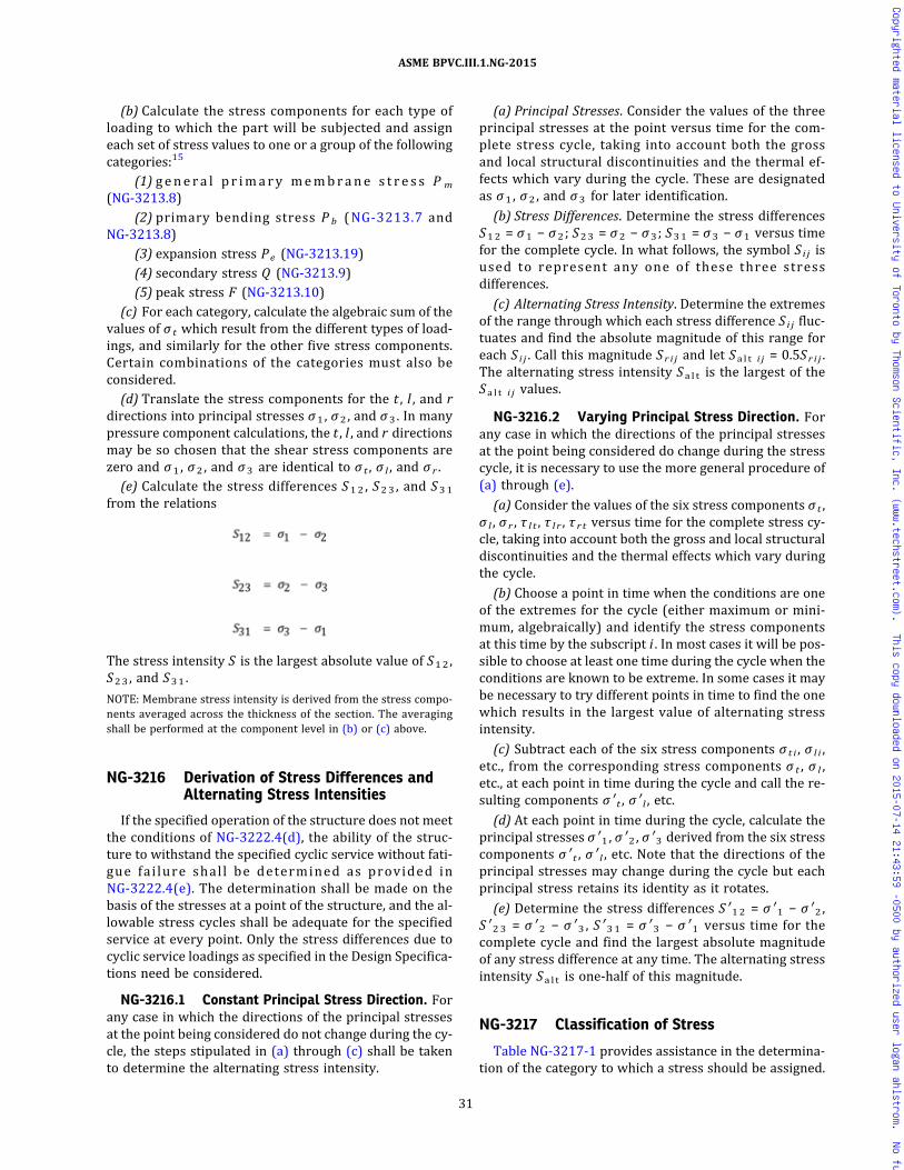
(b) Calculate the stress components for each type ofloading to which the part will be subjected and assigneach set of stress values to one or a group of the followingcategories:15
(1) gene r a l p r ima ry membrane s t r e s s P m
(NG-3213.8)(2) primary bending stress P b (NG-3213.7 and
NG-3213.8)(3) expansion stress Pe (NG-3213.19)(4) secondary stress Q (NG-3213.9)(5) peak stress F (NG-3213.10)
(c) For each category, calculate the algebraic sum of thevalues of σ t which result from the different types of load-ings, and similarly for the other five stress components.Certain combinations of the categories must also beconsidered.
(d) Translate the stress components for the t , l , and rdirections into principal stresses σ1 , σ2 , and σ3 . In manypressure component calculations, the t , l , and r directionsmay be so chosen that the shear stress components arezero and σ1 , σ2 , and σ3 are identical to σ t , σ l , and σ r .
(e) Calculate the stress differences S12 , S23 , and S31
from the relations
The stress intensity S is the largest absolute value of S12 ,S23 , and S31 .
NOTE: Membrane stress intensity is derived from the stress compo-nents averaged across the thickness of the section. The averagingshall be performed at the component level in (b) or (c) above.
NG-3216 Derivation of Stress Differences andAlternating Stress Intensities
If the specified operation of the structure does not meetthe conditions of NG-3222.4(d), the ability of the struc-ture to withstand the specified cyclic service without fati-gue fai lure shal l be determined as provided inNG-3222.4(e). The determination shall be made on thebasis of the stresses at a point of the structure, and the al-lowable stress cycles shall be adequate for the specifiedservice at every point. Only the stress differences due tocyclic service loadings as specified in the Design Specifica-tions need be considered.
NG-3216.1 Constant Principal Stress Direction. Forany case in which the directions of the principal stressesat the point being considered do not change during the cy-cle, the steps stipulated in (a) through (c) shall be takento determine the alternating stress intensity.
(a) Principal Stresses. Consider the values of the threeprincipal stresses at the point versus time for the com-plete stress cycle, taking into account both the grossand local structural discontinuities and the thermal ef-fects which vary during the cycle. These are designatedas σ1 , σ2 , and σ3 for later identification.
(b) Stress Differences. Determine the stress differencesS12 = σ1 − σ2 ; S23 = σ2 − σ3; S31 = σ3 − σ1 versus timefor the complete cycle. In what follows, the symbol Si j isused to represent any one of these three stressdifferences.
(c) Alternating Stress Intensity. Determine the extremesof the range through which each stress difference Si j fluc-tuates and find the absolute magnitude of this range foreach S i j . Call this magnitude Sr i j and let Sa l t i j = 0.5Sr i j .The alternating stress intensity Sa l t is the largest of theSa l t i j values.
NG-3216.2 Varying Principal Stress Direction. Forany case in which the directions of the principal stressesat the point being considered do change during the stresscycle, it is necessary to use the more general procedure of(a) through (e).
(a) Consider the values of the six stress components σ t ,σ l , σ r , τ l t , τ l r , τ r t versus time for the complete stress cy-cle, taking into account both the gross and local structuraldiscontinuities and the thermal effects which vary duringthe cycle.
(b) Choose a point in time when the conditions are oneof the extremes for the cycle (either maximum or mini-mum, algebraically) and identify the stress componentsat this time by the subscript i . In most cases it will be pos-sible to choose at least one time during the cycle when theconditions are known to be extreme. In some cases it maybe necessary to try different points in time to find the onewhich results in the largest value of alternating stressintensity.
(c) Subtract each of the six stress components σ t i , σ l i ,etc., from the corresponding stress components σ t , σ l ,etc., at each point in time during the cycle and call the re-sulting components σ ′ t , σ ′ l , etc.
(d) At each point in time during the cycle, calculate theprincipal stresses σ ′1 , σ ′2 , σ ′3 derived from the six stresscomponents σ ′ t , σ ′ l , etc. Note that the directions of theprincipal stresses may change during the cycle but eachprincipal stress retains its identity as it rotates.
(e) Determine the stress differences S ′12 = σ ′1 − σ ′2 ,S ′23 = σ ′2 − σ ′3 , S ′31 = σ ′3 − σ ′1 versus time for thecomplete cycle and find the largest absolute magnitudeof any stress difference at any time. The alternating stressintensity Sa l t is one‐half of this magnitude.
NG-3217 Classification of Stress
Table NG-3217-1 provides assistance in the determina-tion of the category to which a stress should be assigned.
31
ASME BPVC.III.1.NG-2015
Copyrighted material licensed to University of Toronto by Thomson Scientific, Inc. (www.techstreet.com). This copy downloaded on 2015-07-14 21:43:59 -0500 by authorized user logan ahlstrom. No further reproduction or distribution is permitted.

Table NG-3217-1Classification of Stress Intensities for Some Typical Cases
Core SupportStructure Location Origin of Stress Type of Stress Classification
Discontinuity
Gross Local
Cylindrical orspherical shell
Shell plate remotefromdiscontinuities
Pressure difference General membrane Pm No No
Gradient through plate thickness Q Yes No
Axial thermal gradient Membrane Q Yes No
Bending Q Yes No
Junction withhead or flange
Pressure difference Membrane Q Yes No
Bending Q Yes No
Any shell or head Any section acrossentire shell
External load or moment, orpressure difference
General membrane averaged across fullsection. Stress componentperpendicular to cross section.
Pm No No
External load or moment Bending across full section. Stresscomponent perpendicular to crosssection.
Pm No No
Near nozzle orother opening
External load or moment, orpressure difference
Membrane Q Yes No
Bending Q Yes No
Peak (fillet or corner) F Yes Yes
Any location Temp. difference betweenshell and head
Membrane Q Yes No
Bending Q Yes No
Dished head orconical
Crown Pressure difference General membrane Pm No No
Bending Pb No No
Knuckle ofjunction to shell
Pressure difference Membrane Q [Note (1)] Yes No
Bending Q Yes No
Flat head Center region Pressure difference General membrane Pm No No
Bending Pb No No
Junction to shell Pressure difference Membrane Q Yes No
Bending Q Yes No
Perforated head orshell
Typical ligamentin a uniformpattern
Pressure difference orexternal load
General membrane (avg. through crosssection)
Pm No No
Bending (avg. through width of ligament,but gradient through plate)
Pb No No
Peak F No Yes
Isolated oratypicalligament
Pressure difference Membrane Q Yes No
Bending F Yes Yes
Peak F Yes Yes
Nozzle Cross sectionperpendicularto nozzle axis
Pressure difference orexternal load or moment
General membrane avg. across fullsection. Stress componentperpendicular to section.
Pm No No
External load or moment Bending across nozzle section Pm No No
Nozzle wall Pressure difference General membrane Pm No No
Membrane Q Yes No
Bending Q Yes No
Peak F Yes Yes
Differential expansion Membrane Q Yes No
Bending Q Yes No
Peak F Yes Yes
Cladding Any Differential expansion Membrane F Yes Yes
Bending F Yes Yes
Any Any Radial thermal gradientthrough plate thickness[Note (2)]
Stress due to equivalent bending portion Q [Note (3)] Yes No
Stress due to nonlinear portion F Yes Yes
Any Any Any Stress concentration (notch effect) F Yes Yes
32
ASME BPVC.III.1.NG-2015
Copyrighted material licensed to University of Toronto by Thomson Scientific, Inc. (www.techstreet.com). This copy downloaded on 2015-07-14 21:43:59 -0500 by authorized user logan ahlstrom. No further reproduction or distribution is permitted.
ð15Þ
NG-3220 STRESS LIMITS FOR OTHER THANTHREADED STRUCTURAL FASTENERS
NG-3221 Design Loadings
The stress intensity limits which must be satisfied forthe Design Loadings (NG-3112) stated in the Design Spe-cifications are the three limits of this paragraph and thespecial stress limits of NG-3227. The provisions ofNG-3228 may provide relief from certain of these stresslimits if plastic analysis techniques or tests are applied.The design stress intensity values Sm are given byNG-3229. The limits are summarized by FigureNG-3221-1.
NG-3221.1 General Primary Membrane Stress Inten-sity. This stress intensity (derived from Pm in FigureNG-3221-1) is derived from the average value acrossthe thickness of a section of the general primary stresses(see NG-3213.8) produced by design internal pressuredifference and other specified Design Mechanical Loads,but excluding all secondary and peak stresses. Averagingis to be applied to the stress components prior to determi-nation of the stress intensity values. The allowable valueof the stress intensity is Sm at the Design Temperature.
NG-3221.2 Primary Membrane Plus Primary Bend-ing Stress Intensity. This stress intensity (derived fromPm + Pb in Figure NG-3221-1) is derived from the highestvalue across the thickness of a section of the general pri-mary membrane stresses plus primary bending stressesproduced by Design Pressure Difference and other speci-fied Design Mechanical Loads, but excluding all secondaryand peak stresses. The allowable value of this stress in-tensity is 1.5Sm .
NG-3221.3 External Pressure Difference. The provi-sions of NG-3133 apply.
NG-3222 Level A Service Limits
The Level A Service Limits must be satisfied for the Ser-vice Conditions [NCA‐2142.4(b)(1)] for which these limitsare designated in the Design Specifications and are thefour limits of this paragraph and NG-3227. The provisionsof NG-3228may provide relief from certain of these stresslimits if plastic analysis techniques are applied. The de-sign stress intensity values Sm are given by NG-3229.The limits are summarized by Figure NG-3221-1.
NG-3222.1 Primary Membrane and Bending StressIntensities. The stresses due to primary loads presentedduring normal service must be computed and satisfy thelimits of NG-3221.
NG-3222.2 Primary Plus Secondary StressIntensity.16 This stress intensity is derived from the high-est value at any point across the thickness of a section ofthe general or local primary membrane stresses, plus pri-mary bending stresses, plus secondary stresses, producedby the specified service pressure differences and otherspecified mechanical loads and by general thermal effectsassociated with normal service loadings. The effects ofgross structural discontinuities but not of local structuraldiscontinuities (stress concentrations) shall be included.The allowable value for the maximum range of this stressintensity is 3Sm [Figure NG-3221-1, Note (1)], except forcertain cyclic events which may exceed the 3Sm limit dur-ing the design life of the plant. For this exception, in lieu ofmeeting the 3Sm limit, an elastic–plastic fatigue analysisin accordance with NG-3228.3 may be performed to de-monstrate that the cumulative fatigue usage attributableto the combination of these low cycle events plus all othercyclic events does not exceed a value of 1.0 when calcu-lated in accordance with NG-3222.4.
NG-3222.3 Expansion Stress Intensity.16 This stressintensity is the highest value of stress, neglecting localstructural discontinuities, produced at any point acrossthe thickness of a section by the loadings which resultfrom restraint of free end displacement and the effect ofanchor point motions. The allowable value of the maxi-mum range of this stress intensity when combined withall other primary and secondary stress intensities is 3Sm .
NG-3222.4 Analysis for Cyclic Operation.(a) Suitability for Cyclic Condition. The suitability of a
structure for specified Service Loadings involving cyclicapplication of loads and thermal conditions shall be de-termined by the methods described herein, except thatthe suitability of high strength threaded structural fasten-ers shall be determined by the methods of NG-3232.3(b)and the possibility of thermal stress ratchet shall be in-vestigated in accordance with NG-3222.5. If the specifiedService Loadings of the structure meet all of the condi-tions of (d) below, no analysis for cyclic service is re-quired, and it may be assumed that the limits on peakstress intensities as governed by fatigue have been
Table NG-3217-1Classification of Stress Intensities for Some Typical Cases (Cont'd)
NOTES:(1) Consideration must also be given to the possibility of wrinkling and excessive deformation in shells with large diameter‐to‐thickness
ratio.(2) Consider the possibility of thermal stress ratchet.(3) Equivalent linear stress is defined as the linear stress distribution which has the same net bending moment as the actual stress
distribution.
33
ASME BPVC.III.1.NG-2015
Copyrighted material licensed to University of Toronto by Thomson Scientific, Inc. (www.techstreet.com). This copy downloaded on 2015-07-14 21:43:59 -0500 by authorized user logan ahlstrom. No further reproduction or distribution is permitted.

Figure NG-3221-1Stress Categories and Limits of Stress Intensities for Service Levels A and B
0.67LL
Elastic [Note (5)]
Level Aand
Level BServiceLimits
Stress
Category
Membrane, Pm
[Notes (1), (2), and (3)]
Bending, Pb
[Notes (1), (2), and (3)]
Peak Stresses, F
[Note (1)]
Secondary Stresses
Membrane and Bending, Q
[Notes (1) and (4)]
Primary Stresses
Limit analysis [Note (9)]
Test [Note (11)] (NG-3228.4)
0.44Lu
Sm
or
or
Pm
0.67LL
Elastic [Note (5)]
Limit analysis [Note (9)]
Test [Note (11)] (NG-3228.4)
0.44Lu
1.5Sm
or
or
Pm � Pb
SL
Elastic [Note (6)]
Elastic fatigue [Notes (7) and (8)]
Elastic-plastic fatigue [Notes (7) and (8)] (NG-3222.2)
Plastic [Note (10)]
Test [Note (11)] (NG-3228.4)
0.44Lu
Sa
Sa3Sm
or
or
or
Pm � Pb � Q Pm � Pb � Q � F
Pm � Pb � Q � F
NOTES:(1) The symbols Pm , Pb , Q , and F do not represent single quantities, but rather sets of six quantities representing the six stress components σ t , σ l , σ r , τ l t , τ l r , and τ r t .(2) For configurations where compressive stresses occur, the stress limits shall be reviewed to take into account critical buckling stresses [NG-3211(c)].(3) When loads are transiently applied, consideration should be given to the use of dynamic load amplification.(4) The stresses in Category Q are those parts of the total stress which are produced by thermal gradients, structural discontinuities, etc., and do not include primary stresses which may also
exist at the same point. It should be noted, however, that a detailed stress analysis frequently gives the combination of primary and secondary stresses directly and, when appropriate, thiscalculated value represents the total of Pm + Pb + Q , and not Q alone. Similarly, if the stress in Category F is produced by a stress concentration, the quantity F is the additional stressproduced by the notch, over and above the nominal stress. For example, if a plate has a nominal stress intensity, Pm = S , Pb = 0, Q = 0, and a notch with a stress concentration K is in-troduced, then F = Pm(K − 1) and the peak stress intensity equals Pm + Pm(K − 1) = KPm .
(5) The triaxial stresses represent the algebraic sum of the three primary principal stresses (σ1 + σ2 + σ3) for the combination of stress components. Where uniform tension loading ispresent, triaxial stresses are limited to 4Sm .
(6) This limitation applies to the range of stress intensity. When the secondary stress is due to a temperature excursion at the point at which the stresses are being analyzed, the value of Smshall be taken as the average of the Sm values tabulated in Section II, Part D, Subpart 1, Tables 2A and 2B for the highest and the lowest temperature of the metal during the transient. Whenpart or all of the secondary stress is due to mechanical load, the value of Sm shall be taken as the Sm value for the highest temperature of the metal during the transient.
(7) Sa is obtained from the fatigue curves of Section III Appendices, Mandatory Appendix I. The allowable stress intensity for the full range of fluctuation is 2Sa .(8) Values of Sa l t , calculated on an elastic basis, shall not exceed the Sa value associated with 10 cycles when using the fatigue curves of Section III Appendices, Mandatory Appendix I.(9) LL = lower bound limit load with yield point equal to 1.5Sm (where Sm is the value of allowable stress intensity at temperature as contained in Section II, Part D, Subpart 1, Tables 2A and
2B. The lower bound limit load is here defined as that produced from the analysis of an ideally plastic (nonstrain-hardening) material where deformations increase with no further increasein applied load. The lower bound load is one in which the material everywhere satisfies equilibrium and nowhere exceeds the defined material yield strength using either a shear theory ora strain energy of distortion theory to relate multiaxial yielding to the uniaxial case.
(10) SL denotes the structural action of shakedown load as defined in NG-3213.17, calculated on a plastic basis as applied to a specific location on the structure.(11) Lu is defined in NG-3228.4.
34
ASM
EBPVC.III.1
.NG-2015
Copyrighted material licensed to University of Toronto by Thomson Scientific, Inc. (www.techstreet.com). This copy downloaded on 2015-07-14 21:43:59 -0500 by authorized user logan ahlstrom. No further reproduction or distribution is permitted.

satisfied by compliance with the applicable requirementsfor material, design, fabrication, examination, and testingof this Subsection. If the Service Loadings do not meet allthe conditions of (d) below, a fatigue analysis shall bemade in accordance with (e) below or a fatigue test shallbe made in accordance with Section III Appendices, Man-datory Appendix II, II-1500.
(b) Peak Stress Intensity. This stress intensity is derivedfrom the highest value at any point across the thickness ofa section of all primary, secondary, and peak stresses pro-duced by specified service pressure differences and othermechanical loads, and by general and local thermal effectsassociated with normal Service Conditions and includingthe effects of gross and local structural discontinuities.
(c) Conditions and Procedures. The conditions and pro-cedures of NG-3222.4 are based on a comparison of peakstresses with strain cycling fatigue data. The strain cyclingfatigue data are represented by design fatigue strengthcurves of Section III Appendices, Mandatory Appendix I.These curves show the allowable amplitude Sa of the al-ternating stress intensity component (one‐half of the al-ternating stress intensity range) plotted against thenumber of cycles. This stress intensity amplitude is calcu-lated on the assumption of elastic behavior and, hence,has the dimensions of stress, but it does not represent areal stress when the elastic range is exceeded. The designfatigue curves in Section III Appendices, MandatoryAppendix I are derived from both strain-controlled testdata and load-controlled fatigue data. When strain-controlled test data is used, the fatigue curves are ob-tained from uniaxial strain cycling data in which the im-posed strains have been multiplied by the elasticmodulus and a design margin has been provided so asto make the calculated stress intensity amplitude andthe allowable stress intensity amplitude directly compar-able. The curves have been adjusted, where necessary, toinclude the maximum effects of mean stress, which is thecondition where the stress fluctuates about a mean valuewhich is different from zero. As a consequence of this pro-cedure, it is essential that the requirements of NG-3222.2be satisfied at all times with transient stresses included,and that the calculated value of the alternating stress in-tensity be proportional to the actual strain amplitude. Toevaluate the effect of alternating stresses of varying am-plitudes, a linear damage relation is assumed in (e)(5)below.
(d) Components Not Requiring Analysis for Cyclic Ser-vice. An analysis for cyclic service is not required, and itmay be assumed that the limits on peak stress intensitiesas governed by fatigue have been satisfied for a structureby compliance with the applicable requirements for mate-rial, design, fabrication, examination, and testing of thisSubsection, provided the specified Service17 Loadings ofthe structure or portion thereof meets all the conditionsstipulated in (1) through (4) below.
(1) Temperature Difference— Startup and Shutdown.The temperature difference in °F (°C) between any twoadjacent points18 of the structure during normal servicedoes not exceed Sa/(2Eα), where Sa is the value obtainedfrom the applicable design fatigue curves for the specifiednumber of startup–shutdown cycles, α is the value of theinstantaneous coefficient of thermal expansion at themean value of the temperatures at the two points as givenby Section II, Part D, Subpart 2, Table TE, and E is takenfrom Section II, Part D, Subpart 2, Table TM at the meanvalue of the temperature at the two points.
(2) Temperature Difference — Normal Service. Thetemperature difference in °F (°C) between any two adja-cent points18 does not change19 during normal serviceby more than the quantity Sa/(2Eα), where Sa is the val-ue obtained from the applicable design fatigue curve ofSection III Appendices, Mandatory Appendix I for the totalspecified number of significant temperature differencefluctuations. A temperature difference fluctuation shallbe considered to be significant if its total algebraic rangeexceeds the quantity S /2Eα , where S is defined asfollows:
(-a) If the total specified number of service cyclesis 106 cycles or less, S is the value of Sa obtained from theapplicable design fatigue curve for 106 cycles.
(-b) If the total specified number of service cyclesexceeds 106 cycles, S is the value of Sa obtained from theapplicable design fatigue curve for the maximum numberof cycles defined on the curve.
(3) Temperature Difference — Dissimilar Materials.For structures fabricated frommaterials of differing mod-uli of elasticity and coefficients of thermal expansion orboth, the total algebraic range of temperature fluctuationin °F (°C) experienced by the component during normals e r v i c e d o e s n o t e x c e e d t h e m a g n i t u d eSa/2(E1α1 −E2α2), where Sa is the value obtained fromthe applicable design fatigue curve for the total specifiednumber of significant temperature fluctuations, E1 and E2
are the moduli of elasticity, and α1 and α2 are the valuesof the instantaneous coefficients of thermal expansion atthe mean temperature value involved for the two materi-als of construction (Section II, Part D, Subpart 2, Tables TEand TM). A temperature fluctuation shall be considered tobe significant if its total excursion exceeds the quantity S/2(E1α1 − E2α2), where S is defined as follows:
(-a) If the total specified number of service cyclesis 106 cycles or less, S is the value of Sa obtained from theapplicable design fatigue curve for 106 cycles.
(-b) If the total specified number of service cyclesexceeds 106 cycles, S is the value of Sa obtained from theapplicable design fatigue curve for the maximum numberof cycles defined on the curve. If the two materials usedhave different applicable design fatigue curves, the lowervalue of Sa shall be used in applying the rules of thisparagraph.
35
ASME BPVC.III.1.NG-2015
Copyrighted material licensed to University of Toronto by Thomson Scientific, Inc. (www.techstreet.com). This copy downloaded on 2015-07-14 21:43:59 -0500 by authorized user logan ahlstrom. No further reproduction or distribution is permitted.

(4) Mechanical Loads. The specified full range of me-chanical loads, including pipe reactions and pressure dif-ferences, does not result in load stresses whose rangeexceeds the Sa value obtained from the applicable designfatigue curve of Section III Appendices, MandatoryAppendix I for the total specified number of significantload fluctuations. If the total specified number of signifi-cant load fluctuations exceeds 106, the S a value atN = 106 may be used. A load fluctuation shall be consid-ered to be significant if the total excursion of load stressexceeds the value of Sa , where S is defined as follows:
(-a) If the total specified number of service cyclesis 106 cycles or less, S is the value of Sa obtained from theapplicable design fatigue curve for 106 cycles.
(-b) If the total specified number of service cyclesexceeds 106 cycles, S is the value of Sa obtained from theapplicable design fatigue curve for the maximum numberof cycles defined on the curve.
(e) Procedure for Analysis for Cyclic Loading. If the spe-cified service loadings for the structure do not meet theconditions of (d) above, the ability of the structure towithstand the specified cyclic service without fatigue fail-ure shall be determined as provided herein. The determi-nation shall be made on the basis of the stresses at a pointand the allowable stress cycles shall be adequate for thespecified Service Loadings at every point. Only the stres-ses due to service cycles as specified in the Design Speci-fications need be considered. Compliance with theserequirements means only that the structure is suitablefrom the standpoint of possible fatigue failure; completesuitability for the specified Service Loadings is also de-pendent on meeting the general stress limits ofNG-3222 and any applicable special stress limits ofNG-3227.
(1) Stress Differences. For each condition of normalservice, determine the stress differences and the alternat-ing stress intensity Sa in accordance with NG-3216.
(2) Local Structural Discontinuities. These effectsshall be evaluated by the use of theoretical stress concen-tration factors for all conditions, except that experimen-tally determined fatigue strength reduction factors maybe used when stated herein or when determined in accor-dance with the procedures of Section III Appendices, Man-datory Appendix II, II-1600. Except for the case ofcracklike defects and specific piping geometries for whichspecific values are given in NB‐3680, no fatigue strengthreduction factor greater than 5 need be used.
(3) Design Fatigue Curves. Section III Appendices,Mandatory Appendix I contains the applicable fatigue de-sign curves for the materials permitted by this Subsec-tion. When more than one curve is presented for agiven material, the applicability of each curve to materialof various strength levels is identified. Linear interpola-tion may be used for intermediate strength levels of thesematerials. As used herein the strength level is the speci-fied minimum room temperature value.
(4) E f f ec t o f E las t i c Modulus . Mul t ip ly S a l t
(NG-3216.1 or NG-3216.2) by the ratio of the modulusof elasticity given on the design fatigue curve to the valueof the modulus of elasticity used in the analysis. Enter theapplicable design fatigue curve of Section III Appendices,Mandatory Appendix I at this value on the ordinate axisand find the corresponding number of cycles on the ab-scissa. If the service cycle being considered is the onlyone which produces significant fluctuating stresses, thisis the allowable number of cycles.
(5) Cumulative Damage. If there are two or moretypes of stress cycle which produce significant stresses,their cumulative effect shall be evaluated as stipulatedin Steps 1 through 6 below.
Step 1. Designate the specified number of times eachtype of stress cycle of types 1, 2, 3, etc., will be repeatedduring the life of the component as n 1 , n 2 , n 3 , …, nn ,respectively.
NOTE: In determining n1 , n2 , n3 , …, nn , consideration shall be givento the superposition of cycles of various origins which produce a to-tal stress difference range greater than the stress difference rangesof the individual cycles. For example, if one type of stress cycle pro-duces 1000 cycles of a stress difference variation from zero to+60,000 psi and another type of stress cycle produces 10,000 cyclesof a stress difference variation from zero to −50,000 psi, the twotypes of cycle to be considered are defined by the followingparameters:
Step 2. For each type of stress cycle, determine the al-ternating stress intensity S a l t by the procedures ofNG-3216.1 or NG-3216.2 above. Call these quantitiesSa l t1 , Sa l t2 , Sa l t 3 , …, Sa l t n .
Step 3. For each value Sa l t1 , Sa l t 2 , Sa l t 3 , …, Sa l t n , usethe applicable design fatigue curve to determine the max-imum number of repetitions which would be allowable ifthis type of cycle were the only one acting. Call these val-ues N1 , N2 , N3 , …, Nn .
Step 4. For each type of stress cycle, calculate the usagefactors U1 , U2 , U3 , …, Un , from U1 = n1/N1 , U2 = n2/N2 ,U3 = n3/N3 , …, Un = nn/Nn .
Step 5. Calculate the cumulative usage factor U fromU = U1 + U2 + U3 + … + Un .
Step 6. The cumulative usage factor U shall not exceed1.0.
NG-3222.5 Thermal Stress Ratchet. It should benoted that under certain combinations of steady stateand cyclic loadings there is a possibility of large distor-tions developing as the result of ratchet action; that is,
36
ASME BPVC.III.1.NG-2015
Copyrighted material licensed to University of Toronto by Thomson Scientific, Inc. (www.techstreet.com). This copy downloaded on 2015-07-14 21:43:59 -0500 by authorized user logan ahlstrom. No further reproduction or distribution is permitted.

the deformation increases by a nearly equal amount foreach cycle. Examples of this phenomenon are treated inthis subparagraph and in NG-3227.3.
(a) The limiting value of the maximum cyclic thermalstress permitted in a portion of an axisymmetric shellloaded by steady‐state internal pressure difference in or-der to prevent cyclic growth in diameter is as follows:
Let y ′ = maximum allowable range of thermal stresscomputed on an elastic basis divided by theyield strength Sy
20
x = maximum general membrane stress due to pres-sure difference divided by the yield strengthSy
20
(1) Case 1 — linear variation of temperaturethrough the wall
(2) Case 2 — parabolic constantly increasing orconstantly decreasing variation of temperaturethrough the wall
y ′ = 5.2(1 − x) for 0.615 < x < 1.0 and approximatelyfor x < 0.615 as follows:for x = 0.3, 0.4, 0.5y ′ = 4.65, 3.55, 2.70
(b) Use of yield strength Sy in the above relations in-stead of the proportional limit allows a small amount ofgrowth during each cycle until strain hardening raisesthe proportional limit to Sy . If the yield strength of thematerial is higher than two times the Sa value for themaximum number of cycles on the applicable fatiguecurve of Figs. I‐9.0 for the material, the latter value shallbe used if there is to be a large number of cycles becausestrain softening may occur.
NG-3222.6 Deformation Limits. Any deformationlimits prescribed by the Design Specifications shall besatisfied.
NG-3223 Level B Service Limits
For components operating within the temperature lim-its of this Section the requirements of (a) and (b) apply.
(a) The Level A Service Limits in NG-3222 shall applyto Service Level B, except that the primary stress intensitylimits shall be increased by 10%.
(b) The Design Specifications shall be satisfied.
NG-3224 Level C Service Limits
Level C Service Limits must be satisfied for ServiceLoadings for which they are designated by the DesignSpecifications and are those of one of the five methodspermitted in NG-3224.1. These stress intensity limitsare summarized by Figure NG-3224-1. Dynamic
instability shall be considered in meeting the load, stress,and deformation limits. The requirements of NG-3224.2through NG-3224.6 shall also be met.
NG-3224.1 Stress Intensity Limits.(a) Elastic Analysis Method(1) The general primary membrane stress intensity
(NG-3213.6, NG-3213.8, and NG-3221.1) shall not exceed1.5 times the allowable stress intensity Sm as given in Sec-tion II, Part D, Subpart 1, Tables 2A and 2B.
(2) The primary membrane plus primary bendingstress intensity (NG-3213.7, NG-3213.8, and NG-3221.3)shall not exceed 2.25 times the allowable stress intensitySm as given in Section II, Part D, Subpart 1, Tables 2A and2B.
(b) Limit Load Analysis. Instead of the elastic analysis of(a), a limit load analysis may be performed as set forthbelow.
(1) The lower bound limit load LL is determined withmaterial yield point equal to 1.5 times the allowablestress intensity Sm at temperatures where Sm is givenin Section II, Part D, Subpart 1, Tables 2A and 2B. The low-er bound limit load (NG-3213.21) is that load, determinedfrom the analysis (NG-3213.20) of an ideally plastic(nonstrain‐hardening) material, which produces increas-ing deformations with no further increase in applied load.The lower bound load is one in which the material every-where satisfies equilibrium and nowhere exceeds the de-fined material yield strength, using either the maximumshear stress theory or a strain energy of distortion theoryto relate multiaxial yielding to the uniaxial case.
(2) For Service Loadings for which Level C Limits aredesignated, the general primary membrane stress inten-sity shall not exceed the lower bound limit load LL .
(3) For Service Loadings for which Level C Limits aredesignated, the general primary membrane plus primarybending stress intensities shall not exceed the lowerbound limit load LL .
(c) Plastic Analysis. Instead of the elastic analysis of (a),a plastic analysis may be performed as set forth in (1) and(2) below.
(1) For Service Loadings for which Level C Limits aredesignated, general primary membrane stress intensityvalues shall not exceed 1.5 times the allowable stress in-tensity Sm at temperatures where Sm is given in SectionII, Part D, Subpart 1, Tables 2A and 2B.
(2) For Service Loadings for which Level C Limits aredesignated, the general primary membrane plus primarybending stress intensities shall not exceed the greater ofeither one‐half of the ultimate strength values at tempera-ture or 2.25 times the allowable stress intensity values Smat temperature as given in Section II, Part D, Subpart 1,Tables 2A and 2B.
(d) Stress Ratio Analysis. Instead of the elastic analysisof (a), a stress ratio analysis (NG-3213.22) may be per-formed, in which event the limits of (1) and (2) belowshall be met.
37
ASME BPVC.III.1.NG-2015
Copyrighted material licensed to University of Toronto by Thomson Scientific, Inc. (www.techstreet.com). This copy downloaded on 2015-07-14 21:43:59 -0500 by authorized user logan ahlstrom. No further reproduction or distribution is permitted.
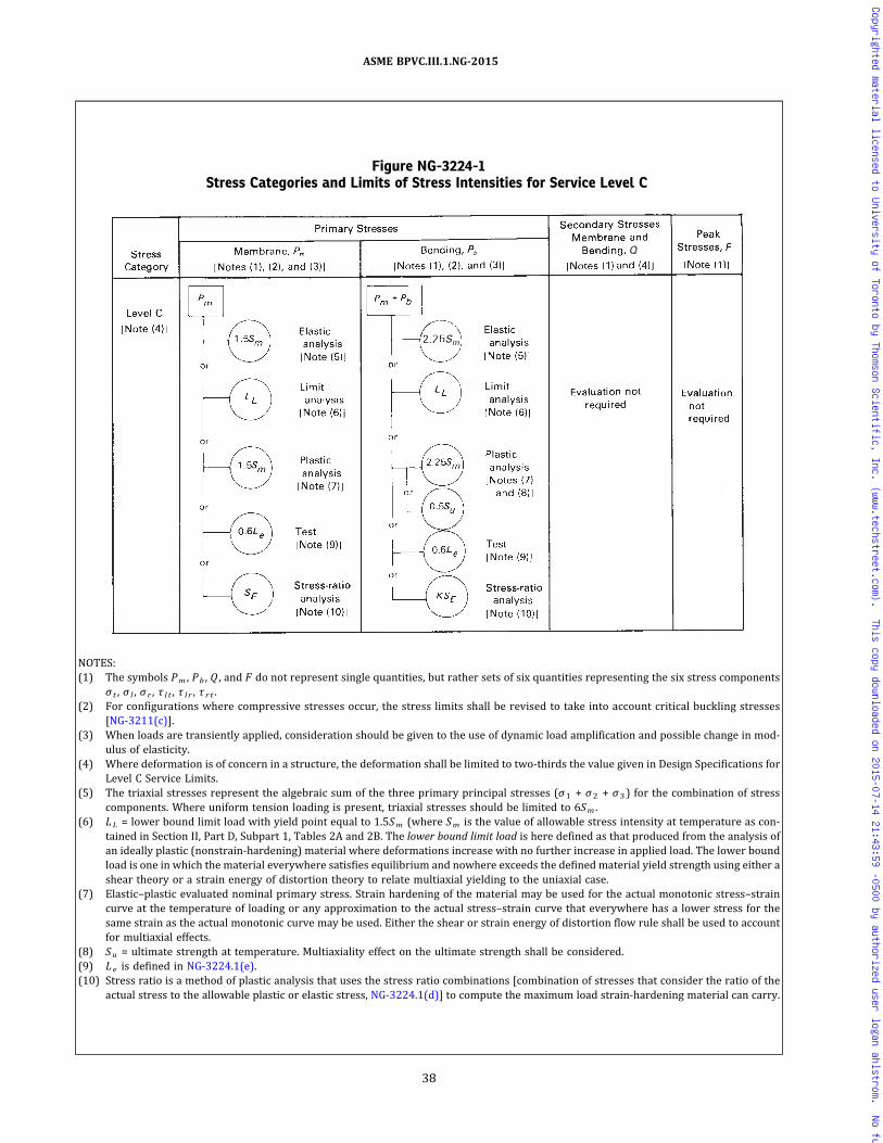
Figure NG-3224-1Stress Categories and Limits of Stress Intensities for Service Level C
Sm
Q
NOTES:(1) The symbols Pm , Pb , Q , and F do not represent single quantities, but rather sets of six quantities representing the six stress components
σ t , σ l , σ r , τ l t , τ l r , τ r t .(2) For configurations where compressive stresses occur, the stress limits shall be revised to take into account critical buckling stresses
[NG-3211(c)].(3) When loads are transiently applied, consideration should be given to the use of dynamic load amplification and possible change in mod-
ulus of elasticity.(4) Where deformation is of concern in a structure, the deformation shall be limited to two-thirds the value given in Design Specifications for
Level C Service Limits.(5) The triaxial stresses represent the algebraic sum of the three primary principal stresses (σ1 + σ2 + σ3) for the combination of stress
components. Where uniform tension loading is present, triaxial stresses should be limited to 6Sm .(6) LL = lower bound limit load with yield point equal to 1.5Sm (where Sm is the value of allowable stress intensity at temperature as con-
tained in Section II, Part D, Subpart 1, Tables 2A and 2B. The lower bound limit load is here defined as that produced from the analysis ofan ideally plastic (nonstrain-hardening) material where deformations increase with no further increase in applied load. The lower boundload is one in which the material everywhere satisfies equilibrium and nowhere exceeds the defined material yield strength using either ashear theory or a strain energy of distortion theory to relate multiaxial yielding to the uniaxial case.
(7) Elastic–plastic evaluated nominal primary stress. Strain hardening of the material may be used for the actual monotonic stress–straincurve at the temperature of loading or any approximation to the actual stress–strain curve that everywhere has a lower stress for thesame strain as the actual monotonic curve may be used. Either the shear or strain energy of distortion flow rule shall be used to accountfor multiaxial effects.
(8) Su = ultimate strength at temperature. Multiaxiality effect on the ultimate strength shall be considered.(9) Le is defined in NG-3224.1(e).(10) Stress ratio is a method of plastic analysis that uses the stress ratio combinations [combination of stresses that consider the ratio of the
actual stress to the allowable plastic or elastic stress, NG-3224.1(d)] to compute the maximum load strain-hardening material can carry.
38
ASME BPVC.III.1.NG-2015
Copyrighted material licensed to University of Toronto by Thomson Scientific, Inc. (www.techstreet.com). This copy downloaded on 2015-07-14 21:43:59 -0500 by authorized user logan ahlstrom. No further reproduction or distribution is permitted.

(1) Service loads producing primary membranestresses shall not result in stress intensities exceedingSE where SE ≤ 2.0Sm .
(2) The stress intensity limits for other stress fieldsshall be as specified in Section III Appendices, Nonmanda-tory Appendix A, Article A-9000. For example, for bending
for rectangular sections, where
where K is the Section Factor for n = 1 as determined bythe method of Section III Appendices, NonmandatoryAppendix A, Article A-9000.
(e) Prototype or Model Tests. For Service Loadings forwhich Level C Limits are designated, the limits of (a) neednot be satisfied if it can be shown from the test of a pro-totype or model that the specified loads (dynamic or sta-tic equivalent) do not exceed 60% of Le , where Le is theultimate load or the maximum load or load combinationused in the test. In using this method, account shall be ta-ken of the size effect and dimensional tolerances whichexist between the actual part and the test part or parts,as well as differences which may exist in the ultimatestrength or other governing material properties of the ac-tual part and the tested parts, to assure that the loads ob-tained from the test are a conservative representation ofthe load carrying capability of the actual structure underpostulated Service Loadings for which Level C Limits aredesignated.
NG-3224.2 External Pressure. The permissibleequivalent static external pressure shall be taken as150% of that permitted by the rules of NG-3133. Wheredynamic pressures are involved, the permissible externalpressure shall satisfy the preceding requirements or belimited to one‐half the dynamic instability pressure.
NG-3224.3 Special Stress Limits. The permissiblevalues for special stress limits shall be taken as 150%of the values given in NG-3227 and NG-3228.1.
NG-3224.4 Secondary and Peak Stresses. The re-quirements of NG-3222.2, NG-3222.4(b), NG-3222.5, andNG-3227.3 need not be satisfied.
NG-3224.5 Fatigue Requirements. Service Loadingsfor which Level C Limits are designated need not be con-sidered when applying the procedures of NG-3222.4(a) todetermine whether or not a fatigue analysis is required.
NG-3224.6 Deformation Limits. Any deformationlimits prescribed by the Design Specifications shall beconsidered [Figure NG-3224-1, Note (4)].
NG-3225 Level D Service Limits
If the Design Specifications specify any Service Load-ings for which Leve l D L imi ts are des ignated[NCA‐2142.4(b)(4)], the rules contained in Section III Ap-pendices, Nonmandatory Appendix F may be used in eval-uating these loadings, independently of all other Designand Service Loadings. In addition, when the special stresslimits of NG-3227 are applicable for Level D Limits, thecalculated stresses shall not exceed twice the stress limitsgiven in NG-3227 as applied for Level A and Level B Ser-vice Limits.
NG-3227 Special Stress Limits
The following deviations from the basic stress limitsare provided to cover special Service Loadings or config-urations. Some of these deviations are more restrictiveand some are less restrictive than the basic stress limits.Rules governing application of these special stress limitsfor Level C and Level D Service Limit applications are con-tained in NG-3224.3 and NG-3225, respectively. In casesof conflict between these requirements and the basicstress limits, the rules of NG-3227 take precedence forthe particular situations to which they apply. NG-3227does not apply to threaded structural fasteners(NG-3230).
NG-3227.1 Bearing Loads.(a) The average bearing stress for resistance to crush-
ing under the maximum load, experienced as a result ofDesign Loadings or of Service Loadings for which LevelA Limits are designated, shall be limited to Sy at tempera-ture, except that when the distance to a free edge is largerthan the distance over which the bearing load is applied, astress of 1.5Sy at temperature is permitted. For clad sur-faces the yield strength of the base metal may be used if,when calculating the bearing stress, the bearing area is ta-ken as the lesser of the actual contact area or the area ofthe base metal supporting the contact surface.
(b)When bearing loads are applied near free edges,such as at a protruding ledge, the possibility of a shearfailure shall be considered. In the case of load stress only,the average shear stress shall be limited to 0.6Sm . In thecase of load stress plus secondary stress, the averageshear stress shall not exceed the following:
(1) for material of Section II, Part D, Subpart 1, Table2A to which Note G7 is applicable and Section II, Part D,Subpart 1, Table 2B to which Note G1 is applicable, thelower of 0.5S y at 100°F (38°C) and 0.675 S y attemperature;
(2) for all other material, 0.5Sy at temperature.(c) For clad surfaces, if the configuration or thickness is
such that a shear failure could occur entirely within theclad material, the allowable shear stress for the claddingshall be determined from the properties of the equivalentwrought material. If the configuration is such that a shearfailure could occur across a path that is partially base
39
ASME BPVC.III.1.NG-2015
Copyrighted material licensed to University of Toronto by Thomson Scientific, Inc. (www.techstreet.com). This copy downloaded on 2015-07-14 21:43:59 -0500 by authorized user logan ahlstrom. No further reproduction or distribution is permitted.

metal and partially clad material, the allowable shearstresses for each material shall be used when evaluatingthe combined resistance to this type of failure.(d)When considering bearing stresses in pins and sim-
ilar members, the Sy at temperature value is applicable,except that a value of 1.5Sy may be used if no credit is gi-ven to bearing area within one pin diameter from a plateedge.
NG-3227.2 Pure Shear.(a) The average primary shear stress across a section
loaded in pure shear, experienced as a result of DesignLoadings or Service Loadings for which Level A Limitsare designated (e.g., keys, shear rings), shall be limitedto 0.6Sm .(b) The maximum primary shear, experienced as a re-
sult of Design Loadings or Service Loadings for which Lev-e l A Limits are des ignated exclus ive of s tressconcentration at the periphery of a solid circular sectionin torsion, shall be limited to 0.8Sm . Primary plus second-ary and peak shear stresses shall be converted to stressintensities (equal to two times pure shear stress) and assuch shall not exceed the basic stress l imits ofNG-3222.2 and NG-3222.4(b).
NG-3227.3 Progressive Distortion of NonintegralConnections. Screwed on caps, screwed in plugs, shearring closures, and breechlock closures are examples ofnonintegral connections which are subject to failure bybell mouthing or other types of progressive deformation.If any combination of applied loads produces yielding,such joints are subject to ratcheting because the matingmembers may become loose at the end of each completeoperating cycle and start the next cycle in a new relation-ship with each other, with or without manual manipula-tion. Additional distortion may occur in each cycle sothat interlocking parts, such as threads, can eventuallylose engagement. Therefore, primary plus secondarystress intensities (NG-3222.2) which result in slippage be-tween the parts of a nonintegral connection in which dis-engagement could occur as a result of progressivedistortion shall be limited to the value Sy (Section II, PartD, Subpart 1, Table Y-1).
NG-3227.4 Triaxial Stresses. The algebraic sum ofthe three primary principal stresses (σ1 + σ2 + σ3) shallnot exceed four times the tabulated value of Sm .
NG-3227.5 Nozzle Piping Transition. The Pm classi-fication of stresses in nozzle resulting from pressure dif-ference, external loads, and moments is applicable forthat length of nozzle which lies within the limits or rein-forcement given by NG-3132, whether or not nozzle rein-f o r c emen t i s p rov ided . Beyond the l im i t s o freinforcement, a Pm classification shall be applied to thegeneral primary membrane stress intensity averagedacross the section (not thickness) resulting from com-bined pressure difference and external mechanical loads;Pm + P b classification shall be applied to primary
membrane plus primary bending stress intensities thatresult from Design Pressure Difference and external me-chanical loads; and a Pm + Pb + Q classification shall beapplied to primary plus secondary stress intensities re-sulting from all loads including external load or momentattributable to restrained free end displacement of the at-tached pipe. Beyond the limits of reinforcement, the 3Smlimit on the range of primary plus secondary stress inten-sity may be exceeded as provided in NG-3228.3 exceptthat in the evaluation of NG-3228.3(a), stresses from at-tached pipe thermal expansion loads and moments mayalso be excluded. The range of membrane plus bendingstress intensity attributable solely to thermal expansionof the attached piping shall be ≤ 3Sm . The nozzle, outsidethe reinforcement limit, shall not be thinner than the larg-er of the pipe thickness or the quantity t p (Smp/Smn )where t p is the nominal thickness of the mating pipe,Smp is the allowable stress intensity value for the pipematerial, and Smn is the allowable stress intensity valuefor the nozzle material.
NG-3227.6 Applications of Elastic Analysis forStresses Beyond the Yield Strength. Certain of the allow-able stresses permitted in the design criteria are such thatthe maximum stress calculated on an elastic basis may ex-ceed the yield strength of the material. The limit on pri-mary p lus secondary s t r es s in tens i t y o f 3S m
(NG-3222.2) has been placed at a level which assures sha-kedown to elastic action after a few repetitions of thestress cycle except in regions containing significant localstructural discontinuities or local thermal stresses. Theselast two factors are considered only in the performance ofa fatigue evaluation. Therefore(a) in evaluating stresses for comparison with the
stress limits on other than fatigue allowables, stressesshall be calculated on an elastic basis(b) in evaluating stresses for comparison with fatigue
allowables, all stresses except those which result from lo-cal thermal stresses [NG-3213.12(b)] shall be evaluatedon an elastic basis. In evaluating local thermal stresses,the elastic equations shall be used except that the numer-ical value substituted for Poisson’s ratio shall be deter-mined from the expression
where
Sa = alternating stress intensity determined inNG-3222.4(e) prior to the elastic modulus adjust-ment in NG-3222.4(e)(4)
Sy = the yield strength of the material at the mean valueof the temperature of the cycle
40
ASME BPVC.III.1.NG-2015
Copyrighted material licensed to University of Toronto by Thomson Scientific, Inc. (www.techstreet.com). This copy downloaded on 2015-07-14 21:43:59 -0500 by authorized user logan ahlstrom. No further reproduction or distribution is permitted.

NG-3228 Applications of Plastic Analysis
The following subparagraphs provide guidance in theapplication of plastic analysis and some relaxation ofthe basic stress limits which are allowed if plastic analysisis used.
NG-3228.1 Plastic Analysis. The limits on primaryplus secondary stress intensity (NG-3222.2), thermalstress ratchet in shell (NG-3222.5), and progressive dis-tortion of nonintegral connections (NG-3227.3) need notbe satisfied at a specific location if, at the location, the pro-cedures of (a) through (c) are used.
(a) In evaluating stresses for comparison with the re-maining stress limits, the stresses are calculated on anelastic basis.
(b) In lieu of satisfying the specific requirements ofNG-3222.2, NG-3222.5, and NG-3227.3 at a specific loca-tion, the structural action is calculated on a plastic basis,and the design shall be considered to be acceptable if sha-kedown occurs (as opposed to continuing deformation)and if the deformations which occur prior to shakedowndo not exceed specified limits. However, this shakedownrequirement need not be satisfied provided the followingconditions are met:
(1) The requirements on primary plus secondarystress intensity (NG-3222.2), thermal stress ratchet inshell (NG-3222.5), and progressive distortion of non‐integral connections (NG-3227.3) need not be satisfiedat a specific location, provided that at the location the eva-luation of stresses for comparison with all the other de-sign, service, testing, and special limits specified inNG-3220 is calculated on an elastic basis.
(2) The maximum accumulated strain at any point, asa result of cyclic operations to which plastic analysis is ap-plied, does not exceed 5.0%.
(3) The maximum deformations do not exceed speci-fied limits.
(4) In evaluating stresses for comparison with fati-gue allowables, the numerically maximum principal totalstrain range shall be multiplied by one‐half the modulusof elasticity of the material (Section II, Part D, Subpart2, Table TM) at the mean value of temperature of thecycle.
(5) The material shall have a minimum specifiedyield strength to specified minimum ultimate strength ra-tio of less than 0.80.
(c) In evaluating stresses for comparison with fatigueallowables, the numerically maximum principal totalstrain range which occurs after shakedown shall be multi-plied by one‐half of the modulus of elasticity of the mate-rial (Section II, Part D, Subpart 2, Table TM) at the meanvalue of the temperature of the cycle.
NG-3228.2 Limit Analysis. The limits on primarymembrane stress intensity (NG-3221.1) and primarymembrane plus primary bending stress intensity(NG-3221.2) need not be satisfied at a specific locationif it can be shown by means of limit analysis or by tests
that the specified loadings do not exceed two‐thirds ofthe lower bound collapse load, except for those materialsof Section II, Part D, Subpart 1, Table 2A to which Note G7is applicable and Section II, Part D, Subpart 1, Table 2B towhich Note G1 is applicable. For these latter materials, thespecified loading shall not exceed the product of the ap-plicable permanent strain limiting factor of Section II,Part D, Subpart 1, Table Y-2 times the lower bound col-lapse load.
NG-3228.3 Simplified Elastic–Plastic Analysis. The3Sm limit on the range of primary plus secondary stressintensity (NG-3222.2) may be exceeded, provided thatthe requirements of (a) through (f) below are met
(a) The range of primary plus secondary membraneplus bending stress intensity, excluding thermal bendingstresses, shall be ≤ 3Sm .
(b) The value of Sa used for entering the design fatiguecurve is multiplied by the factor Ke where
Sn = range of primary plus secondary stress intensity
The values of the material parameters m and n for thevarious classes of permitted materials are as follows:
Material m n Tmax, °F (°C)
Low alloy steel 2.0 0.2 700 (370)
Martensitic stainless steel 2.0 0.2 700 (370)
Carbon steel 3.0 0.2 700 (370)
Austenitic stainless steel 1.7 0.3 800 (425)
Nickel–chromium–iron 1.7 0.3 800 (425)
Nickel–copper 1.7 0.3 800 (425)
(c) The rest of the fatigue evaluation stays the same asrequired in NG-3222.4, except that the procedure ofNG-3227.6 need not be used.
(d) The structure meets the thermal ratcheting require-ment of NG-3222.5.
(e) The temperature does not exceed those listed in theabove table for the various classes of materials.
(f) The material shall have a specified minimum yieldstrength to specified minimum tensile strength ratio ofless than 0.80.
NG-3228.4 Tests for Level A and B Service Limits.For Level A and B Service Limits, the limits on primarymembrane plus primary bending need not be satisfiedin a structure if it can be shown from the test of a proto-type or model that the specified loads (dynamic or staticequivalent) do not exceed 44% of Lu , where Lu is the ul-timate load or the maximum load or load combinationused in the test. In using this method, account shall be
41
ASME BPVC.III.1.NG-2015
Copyrighted material licensed to University of Toronto by Thomson Scientific, Inc. (www.techstreet.com). This copy downloaded on 2015-07-14 21:43:59 -0500 by authorized user logan ahlstrom. No further reproduction or distribution is permitted.
taken of the size effect and dimensional tolerances whichmay exist between the actual part and test part or parts,as well as differences which may exist in the ultimatestrength or other governing material properties of the ac-tual part and the tested parts to assure that the loads ob-tained from the test are a conservative representation ofthe load‐carrying capability of the actual structure underthe postulated Service Loading.
NG-3229 Design Stress Values
The design stress intensity values Sm are given in Sec-tion II, Part D, Subpart 1, Tables 2A and 2B for core sup-port structure material . Values for intermediatetemperatures may be found by interpolation. These formthe basis for the various stress limits. Values of yieldstrength are given in Section II, Part D, Subpart 1, TableY-1. Values of the coefficient of thermal expansion arein Section II, Part D, Subpart 2, Table TE, and values ofthe modulus of elasticity are in Section II, Part D, Subpart2, Table TM. The basis for establishing stress values is gi-ven in Section III Appendices, Mandatory Appendix III.The design fatigue curves used in conjunction withNG-3222.4 are those of Section III Appendices, MandatoryAppendix I.
NG-3230 STRESS LIMITS FOR THREADEDSTRUCTURAL FASTENERS
NG-3231 Design Conditions
(a) The rules of this paragraph apply to mechanicalconnections joining parts in core support structures lo-cated within a pressure-retaining boundary. Deviceswhich are used to assemble structural elements of coresupport structures are referred to as threaded structuralfasteners. The design stress intensity values Sm and yieldstrength values Sy for threaded structural fasteners shallbe the values given in Section II, Part D, Subpart 1, Tables2A and 2B and in Section II, Part D, Subpart 1, Table Y-1,respectively.
(b) The special stress limits of NG-3227 do not apply tothreaded structural fasteners. For connections joiningparts of pressure-retaining boundaries see NB‐3230.
NG-3232 Level A Service Limits
The number and cross‐sectional area of threaded struc-tural fasteners shall be such that the stress intensity lim-its of this paragraph are satisfied for the Service Loadingsfor which Level A Limits are designated in the Design Spe-cifications. The stress intensity limits are summarized inFigure NG-3232-1. Any deformation limit prescribed inthe Design Specifications shall be considered. The totalaxial load transferred through the fastener threads shallnot go to or through zero during the specified ServiceLoadings.
NG-3232.1 Average Stress. Elastic analysis of speci-fied conditions shall show that the average primary plussecondary membrane stress including stress from pre-load meets the following requirements:
(a) The maximum value of the membrane stress inten-sity averaged across either the area of the fastener shankor the tensile stress area of the threads shall be no greaterthan the lesser of either 0.9Sy or 2/3Su , where Sy and Suare determined at service temperature.
(b) The average shear stress across the threads whenloaded in pure shear shall be no greater than 0.6Sy , whereSy is determined at service temperature.
(c) The average value of bearing stress under the fas-tener head shall be no greater than 2.7Sy , where Sy is de-termined at service temperature.
(d) The primary membrane stress intensity Pm dueonly to Design Mechanical Loads applied to the fastenershall be no greater than Sm , where Sm is determined atservice temperature.
(e) If a tight joint is required, the stress due to preloadshall be greater than that due to primary and secondarymembrane stress excluding preload.
(f) The primary shear stress across the threads whenloaded in pure shear due only to Design Mechanical Loadsapplied to the fastener shall be no greater than 0.6Sm ,where Sm is determined at service temperature.
NG-3232.2 Maximum Stress.
(a) The maximum primary membrane and bendingplus secondary membrane and bending stress intensities,produced by the combination of all primary loads and sec-ondary loads but excluding effects of stress concentra-tions, shall be no greater than 1.33 times the limits ofNG-3232.1(a).
(b) For torquing during installation of fasteners, themaximum value of membrane stress intensity shall beno greater than 1.2 times the limits of NG-3232.1(a),and the maximum value of membrane plus bending stressintensity shall be no greater than 1.2 times the limits of(a) at installation temperature.
NG-3232.3 Fatigue Analysis of Threaded StructuralFasteners. Unless threaded structural fasteners meet theconditions of NG-3222.4(d) and thus require no fatigueanalysis, the suitability of threaded structural fastenersfor cyclic service shall be determined in accordance withthe procedures of (a) through (e) below.
(a) Threaded Structural Fasteners Having Less Than100 ksi (690 MPa) Tensile Strength. Fasteners made of ma-terial which has specified minimum tensile strength ofless than 100 ksi (690 MPa) shall be evaluated for cyclicservice by the methods of NG-3222.4(e), using the applic-able design fatigue curves of Section III Appendices, Man-datory Appendix I and an appropriate fatigue strengthreduction factor [see (c)].
42
ASME BPVC.III.1.NG-2015
Copyrighted material licensed to University of Toronto by Thomson Scientific, Inc. (www.techstreet.com). This copy downloaded on 2015-07-14 21:43:59 -0500 by authorized user logan ahlstrom. No further reproduction or distribution is permitted.

ð15Þ NG-3232-1Stress Intensity Limits for Design of Threaded Structural Fasteners
0.9Sy
For Level A and Level B
Service Limits [Notes (9) and (10)]
Stress
Categories Peak Stresses
Primary Membrane and Bending
Plus Secondary Membrane and
Bending
[Notes (2) and (3)]
Average Primary Membrane
Plus Secondary
Membrane Including
Stress From Preload
[Notes (1) and (2)]
Shank or threads [Note (4)] (NG-3232.1)
or
or
or
2/3Su [Note (5)]
0.67LL Limit analysis [Note (7)]
0.44Lu
0.6Sy
Test [Note (8)]
Thread shear (NG-3232.1)
2.7Sy Bearing under head
Sm Shank or threads
1.2Sy Shank or threads [Note (4)]
or
or
or
0.67LL Limit analysis [Note (7)]
(NG-3232.3) [Note (6)]
8/9Su (NG-3232.2) [Note (5)]
0.44Lu Test [Note (8)]
Pm � Qm Pm � Qm � Pb � QB
Sa
Pm � Qm � Pb � QB � F
Pm
NOTES:(1) If a tight joint is required, the stress due to preload should exceed that due to primary plus secondary membrane other than preload.(2) Qm are secondary membrane stresses.(3) QB are secondary bending stresses.
43
ASM
EBPVC.III.1
.NG-2015
Copyrighted material licensed to University of Toronto by Thomson Scientific, Inc. (www.techstreet.com). This copy downloaded on 2015-07-14 21:43:59 -0500 by authorized user logan ahlstrom. No further reproduction or distribution is permitted.

NG-3232-1Stress Intensity Limits for Design of Threaded Structural Fasteners (Cont'd)
NOTES (CONT'D):(4) For torquing during installation, the maximum membrane stress intensity shall not exceed 1.2 times these values at installation temperature.(5) Figure NG-3224-1, Note (5).(6) Figure NG-3221-1, Note (7) and Note (8).(7) Figure NG-3221-1, Note (9).(8) Lu is defined in NG-3228.4.(9) For Level C Service Limits, comply with NG-3234.(10) For Level D Service Limits, comply with NG-3235.
44
ASM
EBPVC.III.1
.NG-2015
Copyrighted material licensed to University of Toronto by Thomson Scientific, Inc. (www.techstreet.com). This copy downloaded on 2015-07-14 21:43:59 -0500 by authorized user logan ahlstrom. No further reproduction or distribution is permitted.

(b) High‐Strength Threaded Structural Fasteners. High‐strength fasteners may be evaluated for cyclic serviceby the methods of NG-3222.4(e) using the applicable de-sign fatigue curve of Section III Appendices, MandatoryAppendix I, provided
(1) the maximum value of primary and secondarystresses, including preload, at the periphery of the fasten-er cross section (resulting from direct tension plus bend-ing and neglecting stress concentrations) shall not exceed0.9Sy , where Sy is determined at service temperature
(2) threads shall have a minimum thread root radiusno smaller than 3 mils (0.08 mm)
(3) fillet radii at the end of the shank shall be suchthat the ratio of fillet radius to shank diameter is not lessthan 0.06
(c) Fatigue Strength Reduction Factor (NG-3213.16).Unless it can be shown by analysis or tests that a lowervalue is appropriate, the fatigue strength reduction factorused in the fatigue evaluation of threaded members shallnot be less than 4. However, when applying the rules of(b) for high‐strength fasteners, the value used shall notbe less than 4.
(d) Effect of Elastic Modulus. Multiply Sa l t (NG-3216.1or NG-3216.2) by the ratio of the modulus of elasticity gi-ven on the design fatigue curve to the value of the modu-lus of elasticity used in the analysis. Enter the applicabledesign fatigue curve at this value on the ordinate axis andfind the corresponding number of cycles on the abscissa.If the service cycle being considered is the only one whichproduces significant fluctuating stresses, this is the allow-able number of cycles.
(e) Cumulative Damage. The fasteners shall be accept-able for the specified cyclic application of loads and ther-mal stress provided the cumulative usage factor U asdetermined in NG-3222.4(e)(5) does not exceed 1.
NG-3233 Level B Service Limits
Level A Service Limits (NG-3232) apply.
NG-3234 Level C Service Limits for ThreadedStructural Fasteners
The number and cross‐sectional area of threaded struc-tural fasteners shall be such that the requirements ofNG-3224 are satisfied for the Service Loadings for whichLevel C Limits are designated in the Design Specifications.For high‐strength structural fasteners [specified mini-mum tensile strength Su ≥ 100 ksi (690 MPa)], the limitsof NG-3232.1 and NG-3232.2(a) also apply for these Ser-vice Loadings. Any deformation limit prescribed in theDesign Specifications shall be considered.
NG-3235 Level D Service Limits for ThreadedStructural Fasteners
The number and cross‐sectional area of threaded struc-tural fasteners shall be such that the requirements ofNG-3225 are satisfied for the Service Loadings for which
Level D Limits are designated [NCA‐2142.4(b)(4)] in theDesign Specifications. Any deformation limit prescribedin the Design Specifications shall be considered.
NG-3300 CORE SUPPORT STRUCTUREDESIGN
NG-3310 GENERAL REQUIREMENTSNG-3311 Acceptability
The requirements for acceptability of a core supportstructure design are given in (a) through (c).
(a) The design shall be such that the requirements ofNG-3100 and NG-3200 are satisfied.
(b) The requirements of NG-3300 are satisfied. In caseof conflict between NG-3200 and NG-3300, the require-ments of NG-3300 shall govern.
(c) The requirements of this subarticle apply to inter-nal structures, NG-1122, only as specifically stipulatedby the Certificate Holder; however, the Certificate Holdershall certify that the design used for the internal struc-tures shall not adversely affect the integrity of the coresupport structure.
NG-3320 DESIGN CONSIDERATIONSNG-3321 Design and Service Loadings
The provisions of NG-3110 apply.
NG-3322 Special Considerations
The provisions of NG-3120 apply.
NG-3323 General Design Rules
The provisions of NG-3130 apply, except when theyconflict with rules of this subarticle. In case of conflict,this subarticle governs in the design of core supportstructures.
NG-3350 DESIGN FOR WELDED CONSTRUCTIONNG-3351 Welded Joint Categories
(a) The term category as used herein defines the loca-tion of a joint. The categories established by this para-graph are for use elsewhere in this Subsection toidentify special restrictions regarding type of joint per-mitted for the location. Figures NG-3351(a)-1 andNG-3351(a)-2 illustrate locations of some typical weldedjoints in each category. Joints whose design functions areneither to restrain nor support the core do not fall intoany category.
(b) The types of joints that may be used at the variouslocations are defined in NG-3352.
NG-3351.1 Joints of Category A. Joints of Category Aare longitudinal joints in cylindrical members. Category Ajoints may be of Type I, II, or, with the following
45
ASME BPVC.III.1.NG-2015
Copyrighted material licensed to University of Toronto by Thomson Scientific, Inc. (www.techstreet.com). This copy downloaded on 2015-07-14 21:43:59 -0500 by authorized user logan ahlstrom. No further reproduction or distribution is permitted.
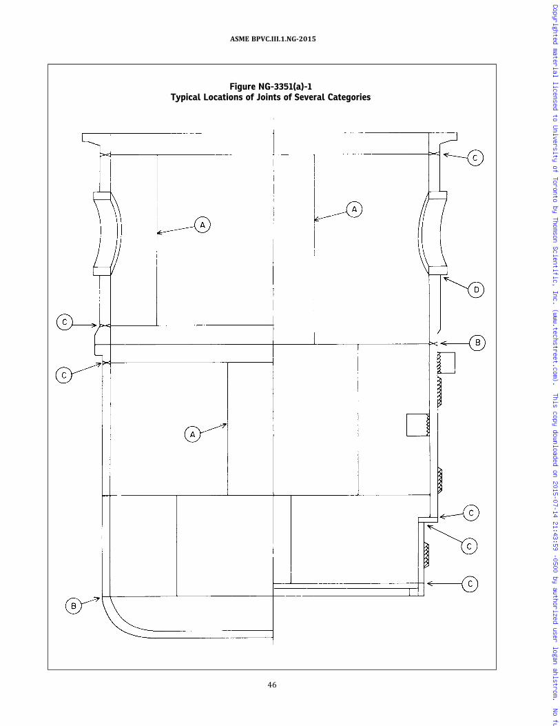
Figure NG-3351(a)-1Typical Locations of Joints of Several Categories
46
ASME BPVC.III.1.NG-2015
Copyrighted material licensed to University of Toronto by Thomson Scientific, Inc. (www.techstreet.com). This copy downloaded on 2015-07-14 21:43:59 -0500 by authorized user logan ahlstrom. No further reproduction or distribution is permitted.

Figure NG-3351(a)-2Typical Welded Joint Category Locations
47
ASME BPVC.III.1.NG-2015
Copyrighted material licensed to University of Toronto by Thomson Scientific, Inc. (www.techstreet.com). This copy downloaded on 2015-07-14 21:43:59 -0500 by authorized user logan ahlstrom. No further reproduction or distribution is permitted.

restriction, Type IV. When a Type IV joint is used in Cate-gory A, the quality factor shall be one‐half that permittedfor Type I or II by Table NG-3352-1 for the examinationused.
NG-3351.2 Joints of Category B. Joints of Category Bare girth welds in cylindrical members. Category B jointsmay be of Type I, II, or, with the following restriction,Type IV or V. When Type IV or V joints are used in Cate-gory B, the quality factor shall be one‐half that permittedfor Type I or II by Table NG-3352-1 for the examinationused.
NG-3351.3 Joints of Category C. Joints of Category Care primarily for joining flanges to cylinders. Category Cjoints may be of Type I, II, III, or, with the following re-striction, Type IV or V. When Type IV or V joints are usedin Category C, the quality factor shall be one‐half that per-mitted for Type I or II by Table NG-3352-1 for the exam-ination used.
NG-3351.4 Joints of Category D. Joints of Category Dare primarily for attaching nozzles to other members. Ca-tegory D joints may be of Type I, II, III, IV, V, VI, or VII.
NG-3351.5 Joints of Category E. Joints of Category Eare for joints at the ends of webs of beams. Category Ejoints may be of Type I, II, III, IV, V, VI, VII, or VIII.
NG-3352 Permissible Types of Welded JointsSubject to the limitations given in NG-3351, core sup-
port structures may use any of the types of joints de-scribed in the following subparagraphs, providing thequality factor n and fatigue factor f used in the analysismeet the requirements of Table NG-3352-1 for the meth-od of examination employed. The quality factor is used bymultiplying the allowable stress limit for primary and sec-ondary categories times the quality factor in evaluatingthe design. The use of weld quality factor n is for static,not fatigue applications. In performing a fatigue analysis,use the fatigue factor f , designated in Table NG-3352-1,and the applicable fatigue curve in Section III Appendices,Mandatory Appendix I.
NG-3352.1 Type I Joints. Full penetration welds be-tween plates or other elements that lie approximately inthe same plane or have an offset angle not greater than30 deg meet the intent of this subparagraph when madeeither as double welded butt joints, or with consumableinserts or gas backup, or with metal backing strips thatare later removed, provided the backface of such jointsmeets the requirements of NG-4424.
NG-3352.2 Type II Joints. Full penetration welds be-tween plates or other elements meet the intent of thissubparagraph when made ei ther according to
NG-3352.1 or with edges of the joint prepared with op-posing lips to form an integral backing strip, or with metalbacking strips which are not later removed, except thatthe suitability for cyclic operation shall be analyzed bythe method of NG-3222.4 (when used, backing strips shallbe continuous and any splices shall be full penetrationwelded).
NG-3352.3 Type III Joints. Full penetration welds be-tween plates or other elements that may have an offsetangle up to 90 deg meet the intent of this subparagraphwhen either made according to NG-3352.2 or are cornerwelds. Attachment of connections using deposited weldmetal as reinforcement and oblique connections meetthe intent of this subparagraph.
NG-3352.4 Type IV Joints. Partial penetration weldsof double groove design (minimum depth of each grooveequals one‐eighth times the thickness of the thinnest ele-ment) meet the intent of this subparagraph when the areaof the connection is determined by the product of thethroat thickness times the length of welds.
NG-3352.5 Type V Joints. Double fillet welds meetthe intent of this subparagraph when the area of the con-nection is determined by the product of the theoreticalthroat thickness times the length of the welds (). Jointsmade having one side a single fillet and the other side asingle groove meet the intent of this subparagraph.
NG-3352.6 Type VI Joints. Partial penetration weldsof single groove design meet the intent of this subpara-graph when the area of the connection is determined asthe product of the weld throat thickness times the lengthof weld.
NG-3352.7 Type VII Joints. Single fillet welds meetthe intent of this subparagraph when the area of the con-nection is determined as the product of the theoreticalthroat thickness of the fillet welds times the length ofweld ().
NG-3352.8 Type VIII Joints. Intermittent fillet orplug welds meet the intent of this subparagraph whenthe area of the intermittent fillet weld connection is deter-mined as the product of the theoretical throat thicknesstimes the sum of weld lengths and the area of plug weldconnection is determined as the product of the numberof plug welds times the area of the minimum crosssection.
NG-3352.9 Limitations on Types of Joints. The typeof joint used for service shall be one of those permittedfor the Category of the joint (NG-3351). Reduced qualityfactors must be used for certain types of joints when usedin Categories A, B, and C (Table NG-3352-1).
48
ASME BPVC.III.1.NG-2015
Copyrighted material licensed to University of Toronto by Thomson Scientific, Inc. (www.techstreet.com). This copy downloaded on 2015-07-14 21:43:59 -0500 by authorized user logan ahlstrom. No further reproduction or distribution is permitted.

Table NG-3352-1Permissible Welded Joints and Design Factors
Type of Welded Joint
Permissiblefor CategoryShown Below
Quality Factor and Fatigue Factor [Note (1)]
RT or UT [Note(2)] and PT or
MT ExaminationNG-5220
Progressive PTor MT
ExaminationNG-5231
Root and FinalPT or MT
ExaminationNG-5232
Surface PT or MTExamination
NG-5233
Surface VisualExaminationNG-5260
I. Full penetration A, B, C, D, E n = 1.0 f = 1 n = 0.9 f = 1 n = 0.75 f = 1 n = 0.65 f = 1 n = 0.5 f = 1
II. Full penetration A, B, C, D, E n = 1.0 f = 2 n = 0.9 f = 2 n = 0.75 f = 2 n = 0.65 f = 2 n = 0.5 f = 2
III. Full penetration C, D, E n = 1.0 f = 1 n = 0.9 f = 1[Note (3)]
n = 0.75 f = 1[Note (3)]
n = 0.65 f = 1[Note (3)]
n = 0.5 f = 1[Note (3)]
IV. Double groove (RT not applicable) A, B, C n = 0.5 f = 4 n = 0.45 f = 4 n = 0.4 f = 4 n = 0.35 f = 4 n = 0.25 f = 4D, E n = 0.9 f = 4 n = 0.8 f = 4 n = 0.7 f = 4 n = 0.6 f = 4 n = 0.4 f = 4
V. Double fillet (RT not applicable) B, C n = 0.5 f = 4 n = 0.45 f = 4 n = 0.4 f = 4 n = 0.35 f = 4 n = 0.25 f = 4D, E n = 0.9 f = 4 n = 0.8 f = 4 n = 0.7 f = 4 n = 0.6 f = 4 n = 0.4 f = 4
VI. Single groove (RT not applicable) D, E n = 0.6 f = 4 n = 0.55 f = 4 n = 0.45 f = 4 n = 0.4 f = 4 n = 0.35 f = 4
VII. Single fillet (RT not applicable) D, E n = 0.6 f = 4 n = 0.55 f = 4 n = 0.45 f = 4 n = 0.4 f = 4 n = 0.35 f = 4
VIII. Intermittent fillet or plug E Not applicable n = 0.45 f = 4 n = 0.4 f = 4 n = 0.35 f = 4 n = 0.3 f = 4
NOTES:(1) See NG-3352 for definitions.(2) Electroslag butt welds shall be examined by radiography. Electroslag welds in ferritic material shall also be examined for their full length by the ultrasonic
method after a grain refining heat treatment, when performed, or after a postweld heat treatment.(3) A minimum fatigue strength reduction factor of 1.0 is permitted when both sides of weld are examined; otherwise a factor of 2.0 must be used in analysis
for cyclic operation.
49
ASM
EBPVC.III.1
.NG-2015
Copyrighted material licensed to University of Toronto by Thomson Scientific, Inc. (www.techstreet.com). This copy downloaded on 2015-07-14 21:43:59 -0500 by authorized user logan ahlstrom. No further reproduction or distribution is permitted.

ARTICLE NG-4000FABRICATION AND INSTALLATION
NG-4100 GENERAL REQUIREMENTS
NG-4110 INTRODUCTION(a) Core support structures (NG-1121) shall be manu-
factured and installed in accordance with the require-ments of this Article and shall be manufactured frommaterials which meet the requirements of ArticleNG-2000.(b) The rules of this Article apply to the internal struc-
tures (NG-1122) only as specifically implemented by theCertificate Holder; however, the Certificate Holder shallcertify that each internal structure has been fabricatedso as to avoid creating an adverse effect on the integrityof the core support structure.
NG-4120 CERTIFICATION OF MATERIAL ANDFABRICATION BY CERTIFICATEHOLDER
NG-4121 Means of CertificationThe Certificate Holder for an item shall certify, by appli-
cation of the appropriate Certification Mark and comple-tion of the appropriate data report in accordance withNCA‐8000, that the materials used comply with the re-quirements of Article NG-2000 and that the fabricationand installation comply with the requirements of thisArticle.
NG-4121.1 Certification of Treatments, Tests, andExaminations. If the Certificate Holder performs treat-ments, tests, repairs, or examinations required by otherArticles, he shall certify that he has fulfilled such require-ments. Reports of all required treatments and of the re-sults of all required tests, repairs, and examinationsperformed shall be available to the Inspector.
NG-4121.2 Repetition of Tensile or Impact Tests. Ifduring the fabrication or installation of the item the mate-rial is subjected to heat treatment that has not been cov-ered by treatment of the test coupons (NG-2200), and thatmay reduce either tensile or impact properties below therequired values, the tensile and impact tests shall be re-peated by the Certificate Holder on test specimens takenfrom test coupons which have been taken and treated inaccordance with the requirements of Article NG-2000.
NG-4122 Material IdentificationMaterial for core support structures shall carry identi-
fication markings which will remain distinguishable untilthe core support structure is fabricated or installed. If the
original identification markings are cut off or the materialis divided, the marks shall be accurately transferred to theparts or a coded marking shall be used to assure identifi-cation of each piece of material during subsequent fabri-cation or installation, unless otherwise provided byNG-2150. Material supplied with a Certificate of Compli-ance and welding and brazing material shall be identifiedand controlled so that they can be traced to the core sup-port structure, or else a control procedure shall be em-ployed which ensures that the specified material is used.
NG-4123 Examinations
Visual examination activities that are not referenced forexamination by other specific Code paragraphs, and areperformed solely to verify compliance with requirementsof Article NG-4000, may be performed by the personswho perform or supervise the work. These visual exami-nations are not required to be performed by personneland procedures qualified to NG-5500 and NG-5100, re-spectively, unless so specified.
NG-4125 Testing of Welding Material
All welding material shall meet the requirements ofNG-2400.
NG-4130 REPAIR OF MATERIALNG-4131 Elimination and Repair of Defects
Material originally accepted on delivery in which de-fects exceeding the limits of NG-2500 are known or dis-covered during the process of fabrication or installationis unacceptable. The material may be used provided thecondition is corrected in accordance with the require-ments of NG-2500 for the applicable product form, except(a) the limitation on the depth of the weld repair does
not apply(b) the time of examination of the weld repairs to weld
edge preparations shall be in accordance with NG-5130
NG-4132 Documentation of Repair Welds of BaseMaterial
The Certificate Holder who makes a repair weld, ex-ceeding in depth the lesser of 3/8 in. (10 mm) or 10% ofthe section thickness, shall prepare a report which shallinclude a chart which shows the location and size of theprepared cavity, the welding material identification, thewelding procedure, the heat treatment, and the examina-tion results of repair welds. In addition, all repair welds
50
ASME BPVC.III.1.NG-2015
Copyrighted material licensed to University of Toronto by Thomson Scientific, Inc. (www.techstreet.com). This copy downloaded on 2015-07-14 21:43:59 -0500 by authorized user logan ahlstrom. No further reproduction or distribution is permitted.

ð15Þ
exceeding an accumulated area of 20% of the area of thepart or 15 in.2 (9 700 mm2), whichever is less, shall re-quire the same documentation as welds exceeding theminimum depth.
NG-4200 FORMING, FITTING, ANDALIGNING
NG-4210 CUTTING, FORMING, AND BENDINGNG-4211 Cutting
Materials may be cut to shape and size by mechanicalmeans, such as machining, shearing, chipping, or grinding,or by thermal cutting.
NG-4211.1 Preheating Before Thermal Cutting.When thermal cutting is performed to prepare weld jointsor edges, to remove attachments or defective material, orfor any other purpose, consideration shall be given to pre-heating the material, using preheat schedules, such assuggested in Section III Appendices, NonmandatoryAppendix D.
NG-4211.2 Material Preparation After Thermal Cut-ting for P-No. 8 Material. When metal is to be removedby thermal cutting methods, additional material shall beremoved by mechanical means to the extent required inthe Design Specifications.
NG-4212 Forming and Bending Processes
Any process may be used to hot or cold form or bendcore support structure material, including weld metal,provided the required dimensions are attained (seeNG-4214), and provided the specified impact propertiesof the material, when required, are not reduced belowthe minimum specified values or they are effectively re-stored by heat treatment following the forming operation.Hot forming is defined as forming with the material tem-perature higher than 100°F (56°C) below the lower trans-formation temperature of the material. When required,the process shall be qualified for impact properties as out-lined in NG-4213.
NG-4213 Qualification of Forming Processes forImpact Property Requirements
A procedure qualification test shall be conducted usingspecimens taken from material of the same specification,grade or class, heat treatment, and with similar impactproperties as required for the material in the structure.These specimens shall be subjected to the equivalentforming or bending process and heat treatment as the ma-terial in the structure. Applicable tests shall be conductedto determine that the required impact properties ofNG-2300 are met after straining.
NG-4213.1 Exemptions. Procedure qualification testsare not required for materials listed in (a) through (f)
(a) hot formed material, such as forgings, in which thehot forming is completed by the Material Organizationprior to removal of the impact test specimens
(b) hot formed material represented by test couponsrequired in either NG-2211 or NG-4121.2 which has beensubjected to heat treatment representing the hot formingprocedure and the heat treatments to be applied to theparts
(c) material which does not require impact tests in ac-cordance with NG-2300
(d)material which has a final strain less than 0.5%(e) material where the final strain is less than that of a
previously qualified procedure for that material(f) material from which the impact testing required by
NG-2300 is performed on each heat and lot, as applicable,after forming
NG-4213.2 Procedure Qualification Test. The proce-dure qualification test shall be performed in the mannerstipulated in (a) through (f).
(a) The tests shall be performed on three differentheats of material both before and after straining to estab-lish the effects of the forming and subsequent heat treat-ment operations.
(b) Specimens shall be taken in accordance with the re-quirements of Article NG-2000 and from the tension sideof the strained material.
(c) The percent strain shall be established by the fol-lowing equations:
For cylinders
For spherical or dished surfaces
For pipe
where
R = nominal bending radius to the center line of thepipe
r = nominal radius of the pipeRf = final radius to center line of shellRo = original radius (equal to infinity for a flat part)t = nominal thickness
(d) The procedure qualification shall simulate the max-imum percent surface strain, employing a bending pro-cess similar to that used in the fabrication of thematerial or by direct tension on the specimen.
(e) Sufficient Cv specimens shall be taken from each ofthe three heats of material to establish a transition curveshowing both the upper and lower shelves. On each of thethree heats, tests consisting of three impact specimensshall be conducted at a minimum of five different
51
ASME BPVC.III.1.NG-2015
Copyrighted material licensed to University of Toronto by Thomson Scientific, Inc. (www.techstreet.com). This copy downloaded on 2015-07-14 21:43:59 -0500 by authorized user logan ahlstrom. No further reproduction or distribution is permitted.

temperatures distributed throughout the transition re-gion. The upper and lower shelves may be establishedby the use of one test specimen each. Depending on theproduct form, it may be necessary to plot the transitioncurves using both lateral expansion and energy level data(NG-2300). In addition, drop weight tests shall be madewhen required by NG-2300.(f) Using the results of the impact test data from each
of three heats, taken both before and after straining, de-termine either
(1) the maximum change in NDT temperature alongwith
(-a) the maximum change of lateral expansion andenergy at the temperature under consideration or
(-b) the maximum change in temperature at thelateral expansion or energy levels under consideration or
(2)where lateral expansion is the acceptance criter-ion (NG-2300), either the maximum change in tempera-ture or the maximum change in lateral expansion
NG-4213.3 Acceptance Criteria for Formed Materi-al. To be acceptable, the formed material used in the com-ponent shall have impact properties before formingsufficient to compensate for the maximum loss of impactproperties due to the qualified forming procedure used.
NG-4213.4 Requalification. A new procedure qualifi-cation test is required when any of the following changesare made:(a) the actual postweld heat treatment time at tem-
perature is greater than previously qualified consideringNG-2211. If the material is not postweld heat-treated,the procedure must be qualified without postweld heattreatment.(b) the maximum calculated strain of the material ex-
ceeds the previously qualified strain by more than 0.5%.(c) preheat over 250°F (120°C) is used in the forming
or bending operation but not followed by a subsequentpostweld heat treatment.
NG-4214 Minimum Thickness of FabricatedMaterial
If any fabrication operation reduces the thickness be-low the minimum required to satisfy the rules of ArticleNG-3000, the material may be repaired in accordancewith NG-4130.
NG-4230 FITTING AND ALIGNINGNG-4231 Fitting and Aligning Methods
Parts that are to be joined by welding may be fitted,aligned, and retained in position during the welding op-eration by the use of bars, jacks, clamps, tack welds, ortemporary attachments.
NG-4231.1 Tack Welds. Tack welds used to securealignment shall either be removed completely, when theyhave served their purpose, or their stopping and startingends shall be properly prepared by grinding or other
suitable means so that they may be satisfactorily incorpo-rated into the final weld. Tack welds shall be made byqualified welders using qualified welding procedures.When tack welds are to become part of the finished weld,they shall be visually examined in accordance withNG-5261 and defective tack welds removed.
NG-4232 Maximum Offset of Aligned Sections
Alignment of sections shall be such that the maximumoffset of the finished welded joint will not be greater than1/2t , where t is the nominal thickness of the thinner sec-tion at the joint. Alternatively, smaller alignment toler-ances may be specified by the Design Specifications.
NG-4232.1 Fairing of Offsets. Any offset within theallowable limit provided shall be faired to at least a 3:1 ta-per, length to offset, over the width of the finished weldor, if necessary, by adding additional weld metal beyondwhat would otherwise be the edge of the weld. In addi-tion, offsets greater than those stated in NG-4232 are ac-ceptable provided the requirements of NG-3200 are met.
NG-4240 REQUIREMENTS FOR WELD JOINTS INCOMPONENTS
NG-4245 Complete Joint Penetration Welds
Complete joint penetration is considered to be achievedwhen the acceptance criteria for the examinations speci-fied by this Subsection have been met. No other examina-tion is required to assess that complete penetration hasbeen achieved.
NG-4300 WELDING QUALIFICATIONS
NG-4310 GENERAL REQUIREMENTSNG-4311 Types of Processes Permitted
Only those welding processes which are capable of pro-ducing welds in accordance with the welding procedurequalification requirements of Section IX and this Subsec-tion may be used for welding core support structure ma-terial or attachments thereto. Any process used shall besuch that the records required by NG-4320 can be pre-pared. Stud welds are not permitted.
NG-4311.2 Capacitor Discharge Welding. Capacitordischarge welding may be used for welding temporary at-tachments and permanent nonstructural attachmentsprovided that(a) temporary attachments are removed in accordance
with the provisions of NG-4430(b),(b) the energy output for permanent nonstructural at-
tachments such as strain gages and thermocouples is lim-ited to 125 W‐sec and the minimum thickness of thematerial to which the attachment is made is greater than0.09 in. (2.3 mm), and
52
ASME BPVC.III.1.NG-2015
Copyrighted material licensed to University of Toronto by Thomson Scientific, Inc. (www.techstreet.com). This copy downloaded on 2015-07-14 21:43:59 -0500 by authorized user logan ahlstrom. No further reproduction or distribution is permitted.
ð15Þ
(c) a Welding Procedure Specification is prepared de-scribing the capacitor discharge equipment, the combina-tion of materials to be joined, and the technique ofapplication; qualification of the welding procedure isnot required.
NG-4311.3 Inertia and Continuous Drive FrictionWelding. Inertia and continuous drive friction weldingshall not be used for the fabrication of core supportstructures.
NG-4320 WELDING QUALIFICATIONS, RECORDS,AND IDENTIFYING STAMPS
NG-4321 Required Qualifications(a) Each Certificate Holder is responsible for the weld-
ing done by his organization, and he shall establish theprocedure and conduct the tests required by this Articleand by Section IX in order to qualify both the welding pro-cedures and the performance of welders and welding op-erators who apply these procedures.
(b) Procedures, welders, and welding operators used tojoin permanent or temporary attachments to core sup-port structure parts and to make permanent or tempor-ary tack welds used in such welding shall also meet thequalification requirements of this Article.
(c) When making procedure test plates for butt welds,consideration shall be given to the effect of angular, lat-eral, and end restraint on the weldment. This applies par-ticularly to material and weld metal of 80.0 ksi (550 MPa)tensile strength or higher and heavy sections of both lowand high tensile strength material. The addition of re-straint during welding may result in cracking difficultiesthat otherwise might not occur.
NG-4322 Maintenance and Certification ofRecords
The Certificate Holder shall maintain a record of theirqualified welding procedures and of the welders andwelding operators qualified by them, showing the dateand results of tests and the identification mark assignedto each welder. These records shall be reviewed, verified,and certified by the Certificate Holder by signature orsome other method of control in accordance with the Cer-tificate Holder’s Quality Assurance Program and shall beavailable to the Authorized Nuclear Inspector.
NG-4322.1 Identification of Joints by Welder orWelding Operator.
(a) Each welder or welding operator shall apply theidentification mark assigned to him by the CertificateHolder on or adjacent to all permanent welded joints orseries of joints on which he welds. The marking shall beat intervals of 3 ft (1 m) or less and shall be done witheither blunt nose continuous or blunt nose interrupteddot die stamps. As an alternative, the Certificate Holdershall keep a record of permanent welded joints in eachitem and of the welders and welding operators used inmaking each of the joints.
(b)When a multiple number of permanent structuralattachment welds, nonstructural welds, fillet welds, sock-et welds, welds of specially designed seals, weld metalcladding, hard surfacing, and tube‐to‐tubesheet weldsare made on an item, the Certificate Holder need not iden-tify the welder or welding operator who welded each in-dividual joint, provided
(1) the Certificate Holder maintains a system thatwill identify the welders or welding operators that madesuch welds on each item so that the Inspector can verifythat the welders or welding operators were all properlyqualified
(2) the welds in each category are all of the sametype and configuration and are welded with the sameWelding Procedure Specification
(c) The identification of welder or welding operator isnot required for tack welds.
NG-4323 Welding Prior to Qualification
No welding shall be undertaken until after the weldingprocedures which are to be used have been qualified.Only welders and welding operators who are qualifiedin accordance with NG-4320 and Section IX shall be used.
NG-4324 Transferring Qualifications
The welding procedure qualifications and the perfor-mance qualification tests for welders and welding opera-tors conducted by one Certificate Holder shall not qualifywelding procedures and shall not qualify welders orwelding operators to weld for any other CertificateHolder except as provided in Section IX.
NG-4330 GENERAL REQUIREMENTS FORWELDING PROCEDUREQUALIFICATION TESTS
NG-4331 Conformance to Section IXRequirements
All welding procedure qualification tests shall be in ac-cordance with the requirements of Section IX as supple-mented by the requirements of this Article.
NG-4333 Heat Treatment of Qualification Weldsfor Ferritic Material
Postweld heat treatment of procedure qualificationwelds shall conform to the applicable requirements ofNG-4600 and Section IX. The postweld heat treatmenttime at temperature shall be at least 80% of the maximumtime to be applied to the weld material. The postweld heattreatment total time may be applied in one heating cycle.
53
ASME BPVC.III.1.NG-2015
Copyrighted material licensed to University of Toronto by Thomson Scientific, Inc. (www.techstreet.com). This copy downloaded on 2015-07-14 21:43:59 -0500 by authorized user logan ahlstrom. No further reproduction or distribution is permitted.

NG-4334 Preparation of Test Coupons andSpecimens
(a) Removal of test coupons from the test weld and thedimensions of specimens made from them shall conformto the requirements of Section IX, except that the removalof impact test coupons and the dimensions of impact testspecimens shall be in accordance with (b).(b)Weld deposit of each process in a multiple process
weld shall, where possible, be included in the impact testspecimens. When each process cannot be included in thefull‐size impact test specimen at the 1/4t location requiredby this Section, additional full‐size specimens shall be ob-tained from locations in the test weld that will ensure thatat least a portion of each process has been included infull‐size test specimens. As an alternative, additional testwelds can be made with each process so that full‐size spe-cimens can be tested for each process.
NG-4334.1 Coupons Representing the Weld Depos-its. Impact test specimens and testing methods shall con-form to NG-2321. The impact specimen shall be locatedso that the longitudinal axis of the specimen is at least1/4t and, where the thickness of the test assembly permits,not less than 3/8 in. (10 mm) from the weld surface of thetest assembly. In addition, when the postweld heat treat-ment temperature exceeds the maximum temperaturespecified in NG-4620 and the test assembly is cooled atan accelerated rate, the longitudinal axis of the specimenshall be a minimum of t from the edge of the test assem-bly. The specimen shall be transverse to the longitudinalaxis of the weld with the area of the notch located in theweld. The length of the notch of the Charpy V‐notch speci-men shall be normal to the surface of the weld. Wheredrop weight specimens are required, the tension surfaceof the specimen shall be oriented parallel to the surfaceof the test assembly.
NG - 4 3 3 4 . 2 C o u p o n s R e p r e s e n t i n g t h eHeat-Affected Zone. Where impact tests of theheat-affected zone are required by NG-4335.2, specimensshall be taken from the welding procedure qualificationtest assemblies in accordance with (a) through (c).(a) If the qualification test material is in the form of a
plate or a forging, the axis of the weld shall be orientedin the direction parallel to the principal direction of roll-ing or forging.(b) The heat-affected zone impact test specimens and
testing methods shall conform to the requirements ofNG-2321.2. The specimens shall be removed from a loca-tion as near as practical to a depth midway between thesurface and center thickness . The coupons forheat-affected zone impact specimens shall be taken trans-verse to the axis of the weld and etched to define theheat-affected zone. The notch of the Charpy V‐notch spe-cimen shall be cut approximately normal to the materialsurface in such a manner as to include as muchheat-affected zone as possible in the resulting fracture.Where the material thickness permits, the axis of a
specimen may be inclined to allow the root of the notchto align parallel to the fusion line. When a grain‐refiningheat treatment is not performed on welds made by theelectroslag or electrogas welding process, the notch forthe impact specimens shall be located in the grain‐coarsened region.(c) For the comparison of heat-affected zone values
with base material values [NG-4335.2(b)], CharpyV‐notch specimens shall be removed from the unaffectedbase material at approximately the same distance fromthe base material surface as the heat-affected zone speci-mens. The axis of the unaffected base material specimensshall be parallel to the axis of the heat-affected zone speci-mens, and the axis of the notch shall be normal to the sur-f a ce o f the base mater i a l . When requ i red byNG-4335.2(b), drop weight specimens shall be removedfrom a depth as near as practical to midway betweenthe surface and center thickness of the unaffected basematerial and shall be tested in accordance with the re-quirements of NG-2321.1.
NG-4335 Impact Test Requirements
When materials are required to be impact tested perNG-2300, impact tests of the weld metal and heat-affectedzone shall be performed in accordance with the followingsubparagraphs. The weld procedure qualification impacttest specimens shall be prepared and tested in accordancewith the applicable requirements of NG-2330 andNG-4334. Retests in accordance with the provisions ofNG-2350 are permitted.
NG-4335.1 Impact Tests of Weld Metal.(a) Impact tests of the weld metal shall be required for
welding procedure qualification tests for production weldjoints exceeding 5/8 in. (16 mm) in thickness when theweld will be made on the surface or will penetrate thebase material that requires impact testing in accordancewith NG-2310. In addition, such testing of the weld metalis required for the welding procedure qualification testsfor any weld repair to base material that requires impacttesting in accordance with NG-2310, regardless of thedepth of the repair.(b) The impact test requirements and acceptance stan-
dards for welding procedure qualification weld metalshall be the same as specified in NG-2330 for the base ma-terial to be welded or repaired. Where two materials areto be joined by welding and have different fracture tough-ness requirements, the test requirements and acceptancestandards of either material may be used for the weld me-tal except where otherwise specified by NCA‐1280 orother parts of this Section.
NG-4335.2 Impact Tests of Heat-Affected Zone.(a) Charpy V‐notch tests of the heat-affected zone of the
welding procedure qualification test assembly are re-quired whenever the thickness of the weld exceeds5/8 in. (16 mm) and either of the base materials requires
54
ASME BPVC.III.1.NG-2015
Copyrighted material licensed to University of Toronto by Thomson Scientific, Inc. (www.techstreet.com). This copy downloaded on 2015-07-14 21:43:59 -0500 by authorized user logan ahlstrom. No further reproduction or distribution is permitted.

impact testing in accordance with the rules of NG-2310.The only exceptions to the requirements are thefollowing:
(1) the qualification for welds in P‐Nos. 1 and 3 andSA-336 F12 materials that are postweld heat-treatedand are made by any process other than electroslag, elec-trogas, or thermit
(2) the qualification for weld deposit cladding orhard‐facing on any base material
(3) that portion of the heat‐affected zone associatedwith GTAW root deposits with a maximum of two layersor 3/16 in. (5 mm) thickness, whichever is less
(b) The required testing shall be in accordance with (c)for base material tested under NG-2332 and in accor-dance with (d) for base material tested under NG-2331.
(c) For heat‐affected zones associated with base mate-rial tested under NG-2332, the required testing shall be inaccordance with (1) through (7).
(1) Determine the TNDT of the unaffected base mate-rial to be used in the welding procedure qualification testassembly.
(2) Charpy V‐notch test specimens representing boththe heat-affected zone and the unaffected base materialshall be tested at the [TNDT + 60°F (33°C)] temperature.
(3) The Charpy V‐notch tests of the unaffected basematerial shall meet the applicable requirements ofNG-2332 or additional testing shall be performed at high-er temperatures until the requirements of NG-2332 aremet.
(4) The heat‐affected zone specimens shall be testedat the test temperature determined in (3). If the averagelateral expansion value of the specimens equals or ex-ceeds the average lateral expansion value of the unaf-fected base material the qualification test is acceptablefor the essential and supplemental essential variables re-corded on the Welding Procedure Qualification Record. Ifthe heat‐affected zone average lateral expansion value isless than the unaffected base material average lateral ex-pansion value, the adjustment given in (5) through (7)shall be determined and applied as provided in (e). Alter-natively, another test coupon may be welded and tested.
(5) Additional Charpy V‐notch tests shall be per-formed on either the heat‐affected zone or the unaffectedbase material, or both, at temperatures where the lateralexpansion value of all three specimens tested is not lessthan 35 mils (0.89 mm). The average lateral expansionvalue for each test meeting this requirement shall beplotted on a lateral expansion versus temperature graph.The difference in temperature THAZ and TUBM where theheat‐affected zone and the unaffected base material aver-age lateral expansion values are the same and not lessthan 35 mils (0.89 mm) shall be used to determine the ad-justment temperature TADJ where
If TADJ ≤ 0, then TADJ = 0.
(6) As an alternative to (5), if the average lateral ex-pansion value of the heat‐affected zone specimens is noless than 35 mils (0.89 mm) and the average of theheat‐affected zone specimens is not less than 5 mils(0.13 mm) below the average lateral expansion value ofthe unaffected base material specimens, TADJ may be ta-ken as 15°F (8°C).
(7) As a second alternative to (5), if the average lat-eral expansion value of the heat‐affected zone specimensis no less than 35 mils (0.89 mm), the difference betweenthe average lateral expansion of the heat‐affected zoneand the unaffected base material specimens shall be cal-culated and used as described in (e)(3).
(d) For heat‐affected zones associated with base mate-rials tested under NG-2331, the required testing shall bein accordance with (1) through (5).
(1) Three Charpy V‐notch specimens shall be re-moved from both the unaffected base material and theheat‐affected zone. The unaffected base material speci-mens shall be tested at the lowest service temperature es-tablished in the Design Specification or additional testingshall be performed at higher temperatures until the ap-plicable requirements of Table NG-2331(a)-1 are metfor the thickness of material to be welded in production.
(2) The heat‐affected zone specimens shall be testedat the test temperature determined in (1). If the averagelateral expansion value of the specimens equals or ex-ceeds the average lateral expansion value of the unaf-fected base material the qualification test is acceptablefor the essential and supplemental essential variables re-corded on the Welding Procedure Qualification Record. Ifthe heat‐affected zone average lateral expansion value isless than the unaffected base material lateral expansionvalue, the adjustment given in (3) through (5) shall be de-termined and applied as provided in (e). Alternatively, an-other test coupon may be welded and tested.
(3) Additional Charpy V‐notch tests shall be per-formed on either the heat‐affected zone or the unaffectedbase material, or both, at temperatures where the lateralexpansion value of all three specimens tested is not lessthan the values shown in Table NG-2331(a)-1 for thethickness of base material to be welded in production.The average lateral expansion value for each test meetingthis requirement shall be plotted on a lateral expansionversus temperature graph. The difference in temperatureTHAZ and TUBM where the heat‐affected zone and the un-affected base material average lateral expansion valuesare the same shall be used to determine the adjustmenttemperature TADJ where
If TADJ ≤ 0, then TADJ = 0.
(4) As an alternative to (3), if the average lateral ex-pansion value of the heat‐affected zone is no less than35 mils (0.88 mm) and the average of the heat‐affected
55
ASME BPVC.III.1.NG-2015
Copyrighted material licensed to University of Toronto by Thomson Scientific, Inc. (www.techstreet.com). This copy downloaded on 2015-07-14 21:43:59 -0500 by authorized user logan ahlstrom. No further reproduction or distribution is permitted.

zone specimens is not less than 5 mils (0.13 mm) belowthe average lateral expansion value of the unaffected basematerial, TADJ may be taken as 15°F (8°C).
(5) As a second alternative to (3), if the average lat-eral expansion value of the heat-affected zone specimensis no less than 35 mils (0.88 mm), the difference betweenthe average lateral expansion of the heat‐affected zoneand the unaffected base material specimens shall be cal-culated and used as described in (e)(3).(e) At least one of the following methods shall be used
to compensate for the heat‐affected zone toughness de-crease due to the welding procedure:
(1) The RTNDT temperature established in NG-2332or the lowest service temperature specified in NG-2331for all of the material to be welded in production WeldingProcedure Specifications supported by this Welding Pro-cedure Qualification Record shall be increased by the ad-justment temperature TADJ .
(2) The specified testing temperature for the produc-tion material may be reduced by TADJ .
(3) The materials to be welded may be welded usingthe Welding Procedure Specification provided they exhi-bit Charpy V‐notch values which are no less than the mini-mum required lateral expansion value required byNG-2300 plus the difference in average lateral expansionvalues established in (c)(7) or (d)(5).(f) The Charpy V‐notch testing results shall be re-
corded on the Welding Procedure Qualification Recordand any offsetting TADJ or increased toughness require-ments shall be noted on the Welding Procedure Qualifica-tion Record and on the Welding Procedure Specification.More than one compensation method may be documen-ted on the Welding Procedure Qualification Record.
NG-4336 Qualification Requirements forBuilt-Up Weld Deposits
Built‐up weld deposits for base metal reinforcementshall be qualified in accordance with the requirementsof NG-4331 to NG-4335, inclusive.
NG-4400 RULES GOVERNING MAKING,EXAMINING, AND REPAIRINGWELDS
NG-4410 PRECAUTIONS TO BE TAKEN BEFOREWELDING
NG-4411 Identification, Storage, and Handling ofWelding Material
Each Certificate Holder is responsible for control of thewelding electrodes and other material which is used inthe fabrication and installation of core support structures(NG-4120). Suitable identification, storage, and handlingof electrodes, flux, and other welding material shall bemaintained. Precautions shall be taken to minimize ab-sorption of moisture by electrodes and flux.
NG-4412 Cleanliness and Protection of WeldingSurfaces
The method used to prepare the base metal shall leavethe weld preparation with reasonably smooth surfaces.The surfaces for welding shall be free of scale, rust, oil,grease, and other deleterious material. The work shallbe protected from deleterious contamination and fromrain, snow, and wind during welding. Welding shall notbe performed on wet surfaces.
NG-4420 RULES FOR MAKING WELDED JOINTSNG-4421 Backing Rings
Backing rings shall conform to the requirements ofNG-3350. The material for backing rings, when used, shallbe compatible with the base metal. Permanent backingrings, when permitted by NG-3350, shall be continuous,and any splices shall be made by full penetration welds.Spacer pins shall not be incorporated into the welds.
NG-4422 Peening
Controlled peening may be performed to minimize dis-tortion. Peening shall not be used on the initial layer, rootof the weld metal, nor on the final layer unless the weld ispostweld heat-treated.
NG-4423 Double Welded Joints
Before applying weld metal on the second side to bewelded, the root of full penetration double welded jointsshall be prepared by suitable methods such as chipping,grinding, or thermal gouging, except for those processesof welding by which proper fusion and penetration areotherwise obtained and demonstrated to be satisfactoryby welding procedure qualification.
NG-4424 Surfaces of Welds
As‐welded surfaces are permitted. However, the sur-face of welds shall be sufficiently free from coarse ripples,grooves, overlaps, abrupt ridges, and valleys to meet thefollowing requirements:(a) The surface condition of the finished weld shall be
suitable for the proper interpretation of radiographicand any other required nondestructive examinations ofthe welds. In those cases where there is a question re-garding the surface condition on the interpretation of aradiographic film, the film shall be compared to the actualweld surface for interpretation and determination ofacceptability.(b) Reinforcements are permitted in accordance with
NG-4426.(c) Undercuts shall not exceed 1/32 in. (0.8 mm) and
shall not encroach on the required section thickness.(d) Concavity on the root side of a single welded cir-
cumferential butt weld is permitted when the resultingthickness of the weld meets the requirements of ArticleNG-3000.
56
ASME BPVC.III.1.NG-2015
Copyrighted material licensed to University of Toronto by Thomson Scientific, Inc. (www.techstreet.com). This copy downloaded on 2015-07-14 21:43:59 -0500 by authorized user logan ahlstrom. No further reproduction or distribution is permitted.

(e) If the surface of the weld requires grinding to meetthe above criteria, care shall be taken to avoid reducingthe weld or base material below the required thickness.
NG-4425 Welding Items of Different DiametersWhen items of different diameters are welded together,
there shall be a gradual transition between the two sur-faces. The length of the transition may include the weld.The slope of the transition shall be such that the length–offset ratio shall not be less than 3:1, unless greater slopesare shown to be acceptable by analysis in accordance withNG-3200.
NG-4426 Reinforcement of WeldsThe surface of the reinforcement of all butt-welded
joints in core support structures may be flush with thebase material or may have uniform crowns. The heightof reinforcement on each face of the weld shall not exceedthe following thickness:
Nominal Thickness,in. (mm)
Maximum Reinforcement,in. (mm)
Up to 1 (25) incl. 3/32 (2.5)
Over 1 to 2 (25 to 50), incl. 1/8 (3.0)
Over 2 to 3 (50 to 75), incl. 5/32 (4.0)
Over 3 to 4 (75 to 100), incl. 7/32 (5.5)
Over 4 to 5 (100 to 125), incl. 1/4 (6.5)
Over 5 (125) 5/16 (8.0)
NG-4427 Shape and Size of Fillet Welds(a) Fillet welds may vary from convex to concave. The
shape and size of the weld shall be in accordance withthe requirements of . A fillet weld in any single continuousweld may be less than the specified fillet weld dimensionby not more than 1/16 in. (1.5 mm), provided that the totalundersize portion of the weld does not exceed 10% of thelength of the weld. Individual undersize weld portionsshall not exceed 2 in. (50 mm) in length. On web‐to‐flangewelds on girders, no underrun is permitted at the ends fora length equal to twice the width of the flange. In makingsocket welds, a gap as shown in shall be provided prior towelding. The gap need not be present nor be verified afterwelding. For sleeve type joints without internal shoulder,the gap shall be between butting ends of the pipe or tube.
(b) Socket welds smaller than those specified in may beused provided the requirements of Article NG-3000 aremet.
NG-4429 Welding of Clad Parts21
The joint types and welding procedures used for clad-ding shall be such as to prevent the formation of brittleweld composition. Any such weld deposited cladding shallbe examined by a liquid penetrant method in accordancewith the requirements of NG-5110 and meet the accep-tance standards of NG-5350. Parts welded to clad itemsshall be welded directly to the base metal and not tothe cladding, except in the case of weld overlay cladding.
NG-4430 WELDING OF TEMPORARYATTACHMENTS AND THEIR REMOVAL
(a) Temporary attachments (NG-1123) may be noncer-tified material and may be welded to the core supportstructure or its parts with continuous or intermittent fil-let or partial penetration welds, provided the followingconditions are met:
(1) the welding procedure and the welders havebeen qualified in accordance with NG-4321.
(2) the material is identified and is suitable forwelding.
(3) the material is compatible with the material towhich it is attached.
(4) the welding material is identified and compatiblewith the materials joined, and
(5) the welds are postweld heat-treated when re-quired by NG-4620.
(b) Removal of temporary attachments shall be accom-plished as follows:
(1) The immediate area around the temporary at-tachment is marked in a suitable manner so that after re-moval the area can be identified until after it has beenexamined in accordance with (3) below.
(2) The temporary attachment is completely re-moved in accordance with the procedures of NG-4211.
(3) After the temporary attachment has been re-moved, the marked area is examined by the liquid pene-trant or magnetic particle method in accordance withthe requirements of NG-5110 and meets the acceptancestandards of NG-5340 or NG-5350, whichever is applic-able; this examination is not required if more than 1/8 in.(3.0 mm) of material will be removed by any subsequentmachining operations.
(4) As an alternative to (a)(5) above, postweld heattreatment may be deferred until after removal of theattachment.
NG-4450 REPAIR OF WELD METAL DEFECTSNG-4451 General Requirements
Defects in weld metal detected by the examinations re-quired by Article NG-5000 shall be eliminated and re-paired when necessary.
NG-4452 Elimination of Surface DefectsWeld metal surface defects may be removed by grind-
ing or machining and need not be repaired by welding,provided that the following requirements are met:
(a) The remaining thickness of the section is not re-duced below that required by Article NG-3000.
(b) The depression, after defect elimination, is blendeduniformly into the surrounding surface.
(c) The area is examined by a magnetic particle or li-quid penetrant method in accordance with NG-5110 afterblending and meets the acceptance standards of NG-5300to ensure that the defect has been removed or the indica-tion reduced to an acceptable limit. Defects detected by
57
ASME BPVC.III.1.NG-2015
Copyrighted material licensed to University of Toronto by Thomson Scientific, Inc. (www.techstreet.com). This copy downloaded on 2015-07-14 21:43:59 -0500 by authorized user logan ahlstrom. No further reproduction or distribution is permitted.

ð15Þ Figure NG-4427-1Fillet and Socket Weld Details and Dimensions
Theoretical throat
Surface of vertical member
Convex fillet weld
Surface of horizontal member
Theoretical throat
Concave fillet weld
Size of weld
Size of weld
Surface of vertical member
(a) Equal Leg Fillet Weld [Note (1)]
Theoretical throat Theoretical throat
Surface of vertical member
Convex fillet weld
Surface of horizontal member
Concave fillet weld
Surface of vertical member
(b) Unequal Leg Fillet Weld [Note (2)]
Face and Back Weld
(c-1) Slip-On Flange (c-2) Socket Welding Flange
Front and Back Weld
x min.x min.
tn
tn or 1/4 in. (6 mm), whichever is smaller
x min.x min.
tn
tn or 1/4 in. (6 mm), whichever is smaller
x min.
x min.tn
1/16 in. (1.5 mm)approx. before welding
(c) Minimum Welding Dimensions for Slip-On and Socket Welding Flanges [Note (3)]
NOTES:(1) The size of an equal leg fillet weld is the leg length of the largest inscribed right isosceles triangle. Theoretical throat = 0.7 × size of weld.(2) The size of an unequal leg fillet weld is the shorter leg length of the largest right triangle which can be inscribed within the fillet weld cross
section.(3) x min. = 1.4tn or the thickness of the hub, whichever is smaller, but not less than 1/8 in. (3 mm), where tn = nominal pipe wall thickness.
58
ASME BPVC.III.1.NG-2015
Copyrighted material licensed to University of Toronto by Thomson Scientific, Inc. (www.techstreet.com). This copy downloaded on 2015-07-14 21:43:59 -0500 by authorized user logan ahlstrom. No further reproduction or distribution is permitted.

the visual or volumetric method and located on an inter-ior surface need only be reexamined by the method whichinitially detected the defect when the interior surface isinaccessible for surface examination.
NG-4453 Requirements for Making Repairs ofWelds
Excavations in weld metal, when repaired by welding,sha l l meet the requ i rements o f the fo l lowingsubparagraphs.
NG-4453.1 Defect Removal. Defects may be re-moved by mechanical means or by thermal gouging pro-cesses. The area prepared for repair shall be examinedby a liquid penetrant or magnetic particle method in ac-cordance with NG-5110 and meet the acceptance stan-dards of NG-5340 or NG-5350. This examination is notrequired where defect elimination removes the full thick-ness of the weld and where the backside of the weld jointis not accessible for removal of examination materials.
NG-4453.2 Requirements for Welding Material,Procedures, and Welders. The weld repair shall be madeusing welding material, welders, and welding proceduresqualified in accordance with NG-4125 and NG-4300.
NG-4453.3 Blending of Repaired Areas. After repairthe surface shall be blended uniformly into the surround-ing surface.
NG-4453.4 Examination of Repair Welds. The exam-ination of a weld repair shall be repeated as required forthe original weld, except that it need only be reexaminedby the liquid penetrant or magnetic particle method whenthe unacceptable indication was originally detected bythe liquid penetrant or magnetic particle method andwhen the repair cavity does not exceed the following:
(a) 1/3t for t ≤ 1/2 in. (13 mm)(b) 1/4 in. (6 mm) for 1/2 in. (13 mm) < t ≤ 21/2 in.
(64 mm)(c) the lesser of 3/8 in. (10 mm) or 10% t for t > 21/2 in.
(64 mm)
where t equals the thickness of the weld.
NG-4500 BRAZING
Brazing is not permitted for core support structures.
NG-4600 HEAT TREATMENT
NG-4610 WELDING PREHEAT REQUIREMENTSNG-4611 When Preheat Is Necessary
The need for and temperature of preheat are depen-dent on a number of factors, such as the chemical analysis,degree of restraint of the parts being joined, elevated tem-perature, physical properties, and material thickness.Some practices used for preheating are given in SectionIII Appendices, Nonmandatory Appendix D as a general
guide for the materials listed by P‐Numbers of SectionIX. It is cautioned that the preheating suggested in SectionIII Appendices, Nonmandatory Appendix D does not ne-cessarily ensure satisfactory completion of the weldedjoint and that the requirements for individual materialswithin the P‐Number listing may be more or less restric-tive. The Welding Procedure Specification for the materialbeing welded shall specify the minimum preheating re-quirements under the welding procedure qualification re-quirements of Section IX.
NG-4612 Preheating MethodsPreheat for welding or thermal cutting, when em-
ployed, may be applied by any method which does notharm the base material or any weld metal already appliedor which does not introduce deleterious material into thewelding area which is harmful to the weld.
NG-4613 Interpass TemperatureConsideration shall be given to the limitations of inter-
pass temperatures for quenched and tempered materialto avoid detrimental effects on the mechanical properties.
NG-4620 POSTWELD HEAT TREATMENTNG-4621 Heating and Cooling Methods
Postweld heat treatment (PWHT) may be accomplishedby any suitable methods of heating and cooling, providedthe required heating and cooling rates, metal tempera-ture, metal temperature uniformity, and temperaturecontrol are maintained.
NG-4622 PWHT Time and TemperatureRequirements
NG-4622.1 General Requirements.4 Except as other-wise permitted in NG-4622.7, all welds, including repairwelds, shall be postweld heat-treated. During postweldheat treatment, the metal temperature shall be main-tained within the temperature range and for the mini-mum holding time specified in Table NG-4622.1-1,except as otherwise permitted in NG-4622.4(c) .P‐Number groups in Table NG-4622.1-1 are in accordancewith Section IX, QW‐420. Except as provided inNG-4624.3, PWHT shall be performed in temperature‐surveyed and ‐calibrated furnaces, or PWHT shall be per-formed with thermocouples in contact with the materialor attached to blocks in contact with the material. In ad-dition, the requirements of the following subparagraphsshall apply.
NG-4622.2 Time–Temperature Recordings. Time–temperature recordings of all postweld heat treatmentsshall be made available for review by the Authorized In-spector. Identification on the time–temperature recordingshall be to the weld, part, or core support structure. Asummary of the time–temperature recording may be pro-vided for permanent records in accordance withNCA‐4134.17.
59
ASME BPVC.III.1.NG-2015
Copyrighted material licensed to University of Toronto by Thomson Scientific, Inc. (www.techstreet.com). This copy downloaded on 2015-07-14 21:43:59 -0500 by authorized user logan ahlstrom. No further reproduction or distribution is permitted.

NG-4622.3 Definition of Nominal Thickness Gov-erning PWHT. The nominal thickness in TableNG-4622.7(b)-1 is the thickness of the weld, the base ma-terial, or the thinner of the base materials being joined,whichever is least. It is not intended that nominal thick-ness include material provided for forming allowance,thinning, or mill overrun when the excess material doesnot exceed 1/8 in. (3 mm). For fillet welds the nominalthickness is the throat thickness, and for partial penetra-tion and material repair welds the nominal thickness isthe depth of the weld groove or preparation.
NG-4622.4 Holding Times at Temperature.
(a) The holding time at temperature as specified inTable NG-4622.1-1 shall be based on the nominal thick-ness of the weld. The holding time need not be continu-ous. It may be an accumulation of the times of multiplepostweld heat treat cycles.
(b) Holding time at temperature in excess of the mini-mum requirements of Table NG-4622.1-1 may be used,provided that specimens so heat-treated are tested in ac-cordance with NG-2200, NG-2400, and NG-4300.
(c) Alternatively, when it is impractical to postweldheat treat at the temperature range specified in TableNG-4622.1-1, it is permissible to perform the postweld
Table NG-4622.1-1Mandatory Requirements for Postweld Heat Treatment (PWHT) of Welds
P‐No. (Sect. IX, QW‐420)
HoldingTemperatureRange, °F (°C)[Note (1)]
Minimum Holding Time at Temperature for Weld Thickness (Nominal), in. (mm)1/2 in.
(13 mm) orLess
Over 1/2 in. (13 mm)to 2 in. (50 mm)
Over 2 in. (50 mm) to5 in. (125 mm) Over 5 in. (125 mm)
1, 3 1100–1250(595–675)
30 min 1 hr/in. (2 min/mm) 2 hr plus 15 min eachadditional inch (2 hplus 0.5 min/mm)over 2 in. (50 mm)
2 hr plus 15 min each additionalinch (2 h plus 0.5 min/mm)over 2 in. (50 mm)
4 1100–1250(595–675)
30 min 1 hr/in. (2 min/mm) 1 hr/in. (2 min/mm) 5 hr plus 15 min each additionalinch (5 h plus 0.5 min/mm)over 5 in. (125 mm)
5A, 5B, 5C, 6 except P‐No. 6Gr. 4
1250–1400(675–760)
30 min 1 hr/in. (2 min/mm) 1 hr/in. (2 min/mm) 5 hr plus 15 min each additionalinch (5 h plus 0.5 min/mm)over 5 in. (125 mm)6 Gr. 4 1050–1150
(565–620)
7 1300–1400(705–760)
30 min 1 hr/in. (2 min/mm) 1 hr/in. (2 min/mm) 5 hr plus 15 min each additionalinch (5 h plus 0.5 min/mm)over 5 in. (125 mm)
9A Gr. 1 1100–1250(595–675)
30 min 1 hr/in. (2 min/mm) 1 hr/in. (2 min/mm) 5 hr plus 15 min each additionalinch (5 h plus 0.5 min/mm)over 5 in. (125 mm)9B Gr. 1 1100–1175
(595–635)
10F Gr. 1 1100–1250(595–675)
30 min 1 hr/in. (2 min/mm) 1 hr/in. (2 min/mm) 5 hr plus 15 min each additionalinch (5 h plus 0.5 min/mm)over 5 in. (125 mm)10I Gr. 1 1300–1400
(705–760)
11A Gr. 4 1000–1050(540–565)
30 min 1 hr/in. (2 min/mm) 1 hr/in. (2 min/mm) 1 hr/in. (2 min/mm)
15E Gr. 1 1350–1425(730–775)
30 min 1 hr/in. (2 min/mm) 1 hr/in. (2 min/mm) 5 hr plus 15 min each additionalinch (5 h plus 0.5 min/mm)over 5 in. (125 mm)
P‐Nos. 8, 34, 42, 43, 45, andhard surfacing on P‐No. 1base metal whosereported carbon contentis not more than 0.30%
PWHT neither required nor prohibited
GENERAL NOTE: Exemptions to the mandatory requirements of this Table are defined in NG-4622.7.
NOTE:(1) All temperatures are metal temperatures.
60
ASME BPVC.III.1.NG-2015
Copyrighted material licensed to University of Toronto by Thomson Scientific, Inc. (www.techstreet.com). This copy downloaded on 2015-07-14 21:43:59 -0500 by authorized user logan ahlstrom. No further reproduction or distribution is permitted.

heat treatment of certain materials at lower temperaturesfor longer periods of time in accordance with TableNG-4622.4(c)-1 and the following:
(1) Except for P‐No. 1 materials, when welds in thematerials listed in Table NG-4622.4(c)-1 are to be post-weld heat-treated at these lower minimum temperatures,impact test specimens for the welding procedure qualifi-cation required by NG-4300 shall be made using the sameminimum temperatures and increased minimum holdingtime. Welding procedures, qualified at the temperaturerange and minimum holding time specified in TableNG-4622.1-1 and at the lower temperature and increasedminimum holding time permitted by this subparagraph,are also qualified for any temperature in between. Whensuch an in‐between temperature is used, the minimumholding t ime shal l be extrapolated from TableNG-4622.1-1 and the alternative requirements of TableNG-4622.4(c)-1.
(2) Except for P‐No. 1 materials, when welds in thematerials listed in Table NG-4622.4(c)-1 are to be post-weld heat-treated at these lower minimum temperatures,the welding material certification required by NG-2400shall be made using the same minimum temperatureand increased minimum holding time. Welding materialcertified at the temperature range and minimum holdingtime specified in Table NG-4622.1-1 and at the lowerminimum temperatures and increased minimum holdingtime permitted by Table NG-4622.4(c)-1 is also certifiedfor any temperatures in between.
(3) Base material certified in accordance withNG-2200 may be postweld heat-treated at the lower mini-mum temperatures and increased minimum holdingtimes without recertification. Postweld heat treatmentat these lower minimum temperatures and increasedminimum holding times may also be the tempering opera-tion, provided a higher tempering temperature is not re-quired by the material specification.
NG-4622.5 PWHT Requirements When DifferentP-Number Materials Are Joined. When materials of twodifferent P‐Number groups are joined by welding, the
applicable postweld heat treatment shall be that specifiedin Table NG-4622.1-1 for the material requiring the high-er PWHT temperature range.
NG-4622.7 Exemptions to Mandatory Require-ments. Postweld heat treatment in accordance with thissubarticle is not required for
(a) nonferrous materials(b) welds exempted in Table NG-4622.7(b)-1(c) welds subjected to temperatures above the PWHT
temperature range specified in Table NG-4622.1-1, pro-vided the Welding Procedure Specification is qualifiedin accordance with Section IX and the base material andthe deposited weld material have been heat-treated atthe higher temperature
(d) postweld heat treatment is not required for coresupport structures constructed of P‐No. 7 Type 405 mate-rial or of Type 410 material with carbon content not ex-ceeding 0.08%, welded with electrodes that produce anaustenitic chromium–nickel weld deposit or a nonair‐hardening nickel–chromium–iron weld deposit, providedthe plate thickness at the welded joint does not exceed3/8 in. (10 mm)
NG-4623 PWHT Heating and Cooling RateRequirements
Above 800°F (425°C) the rate of heating and cooling inany hourly interval shall not exceed 400°F (220°C) di-vided by the maximum thickness in inches of the materialbeing heat-treated, but shall not exceed 400°F (220°C)and need not be less than 100°F (56°C) in any hourly in-terval. During the heating and cooling period there shallnot be a greater variation in temperature than 250°F(138°C) within any 15 ft (4.6 m) interval of weld length.The following exceptions are permitted:
(a) P‐No. 6 material may be cooled in air from the post-weld heat treatment holding temperature specified inTable NG-4622.1-1.
(b) For P‐No. 7 material the cooling rate at tempera-tures above 1200°F (650°C) shall not exceed 100°F/hr(56°C/hr), after which the rate of cooling shall be suffi-ciently rapid to prevent embrittlement.
NG-4624 Methods of Postweld Heat TreatmentThe postweld heat treatment shall be performed in ac-
cordance with the requirements of one of the followingsubparagraphs.
NG-4624.1 Furnace Heating — One Heat. Heatingthe core support structure or item in a closed furnace inone heat is the preferred procedure and should be usedwhenever practical. The furnace atmosphere shall be con-trolled so as to avoid excessive oxidation, and direct im-pingement of flame on the core support structure oritem is prohibited.
NG-4624.2 Furnace Heating — More Than OneHeat. The core support structure or item may be heatedin more than one heat in a furnace, provided the furnace
Table NG-4622.4(c)-1Alternative Holding Temperatures and Times
MaterialP-Numbers
AlternativeMinimum HoldingTemperatures
Alternative MinimumHolding Times
[Note (1)]
1, 3, 9A Gr. 1, 9BGr. 1
1,050°F (565°C) 2 hr/in. (4 min/mm)thickness
1, 3, 9A Gr. 1, 9BGr. 1
1,000°F (540°C) 4 hr/in.(8 min/mm)thickness
NOTE:(1) All other requirements of NG-4622 shall apply.
61
ASME BPVC.III.1.NG-2015
Copyrighted material licensed to University of Toronto by Thomson Scientific, Inc. (www.techstreet.com). This copy downloaded on 2015-07-14 21:43:59 -0500 by authorized user logan ahlstrom. No further reproduction or distribution is permitted.

Table NG-4622.7(b)-1Exemptions to Mandatory PWHT
P‐No. (Sect. IX,QW‐420) Type of Weld [Note (1)] Nominal Thickness (NG-4622.3)
Max.ReportedCarbon, %[Note (2)]
Min. PreheatReq’d., °F (°C)
1 All welds where the materials being joined are11/2 in. (38 mm) and less
11/4 in. (32 mm) or less 0.30 or less …
Over 11/4 in. (32 mm) to 11/2 in. (38 mm) 0.30 or less 200 (95)3/4 in. (19 mm) or less Over 0.30 …
Over 3/4 in. (19 mm) to 11/2 in. (38 mm) … 200 (95)
All welds in material over 11/2 in. (38 mm) 3/4 in. (19 mm) or less … 200 (95)
1 Gr. 1 or Gr. 2 Cladding or repair of cladding [Note (3)] withA‐No. 8 or F‐No. 43 filler metal in basematerial of: 11/2 in. (38 mm) or less
… 0.30 100 (38)
Over 11/2 in. (38 mm) to 3 in. (75 mm) … 0.30 200 (95)[Note (4)]
Over 3 in. (75 mm) … 0.30 250 (120) [Note(5)]
3 except Gr. 3 All welds 1/2 in. (13 mm) or less 0.25 or less 200 (95)
4 All welds in pipes NPS 4 (DN 100) and less ortubes with nominal O.D. 4.5 in. (114 mm) orless
1/2 in. (13 mm) or less 0.15 or less 250 (120)
5A, 5B, 5C All welds in pipes or tubes with maximumspecified chromium 3.00% or less, NPS 4(DN 100) or less pipe, and nominal O.D. 4.5 in.(114 mm) or less tubes
1/2 in. (13 mm) or less 0.15 or less 300 (150)
7 Type 405 and 410S welded with A‐No. 8, A‐No. 9,or F‐No. 43 filler metal
3/8 in. (10 mm) or less 0.08 or less …
9A Gr. 1 All welds provided the procedure qualification ismade using equal or greater thickness basematerial than the production weld
5/8 in. (16 mm) or less … 200 (95)
Attachment welds joining nonpressure-retainingmaterial to pressure‐retaining material over5/8 in. (16 mm)
1/2 in. (13 mm) or less … 200 (95)
Circumferential butt welds or socket welds inpipe NPS 4 (DN 100) or less and tubes withnominal O.D. 4.5 in. (114 mm) or less andattachment welds
1/2 in. (13 mm) or less 0.15 or less 250 (120)
9B Gr. 1 All welds provided the procedure qualification ismade using equal or greater thickness basematerial than the production weld
5/8 in. (16 mm) or less … 200 (95)
Attachment welds joining nonpressure‐retainingmaterial to pressure‐retaining material over5/8 in. (16 mm)
1/2 in. (13 mm) or less … 200 (95)
10I Gr. 1 All welds in material 1/2 in. (13 mm) and less 1/2 in. (13 mm) or less … …
11A Gr. 4 All welds in material 1/2 in. (13 mm) and less 1/2 in. (13 mm) or less … 250 (120)
GENERAL NOTE: The exemptions noted in this table do not apply to electron beam welds in ferritic materials over 1/8 in. (3 mm) inthickness.
NOTES:(1) Where the thickness of material is identified in the Type of Weld column, it is the thickness of the base material at the welded joint.(2) Carbon level of the pressure‐retaining materials being joined.(3) The maximum resulting hardness of the heat-affected zone in the procedure qualification test plate shall not exceed 35 Rc.(4) Intermediate postweld soak at not less than 200°F (95°C) for 2 hr minimum.(5) Intermediate postweld soak at not less than 300°F (150°C) for 2 hr minimum.
62
ASME BPVC.III.1.NG-2015
Copyrighted material licensed to University of Toronto by Thomson Scientific, Inc. (www.techstreet.com). This copy downloaded on 2015-07-14 21:43:59 -0500 by authorized user logan ahlstrom. No further reproduction or distribution is permitted.

atmosphere control requirements of NG-4624.1 applyand overlap of the heated sections of the core supportstructure or item is at least 5 ft (1.5 m). When this proce-dure is used, the portion of the core support structure oritem outside the furnace shall be shielded so that the tem-perature gradient is not harmful. The cross section wherethe core support structure or item projects from the fur-nace shall not intersect a structural discontinuity.
NG-4624.3 Local Heating. Welds may be locallypostweld heat-treated when it is not practical to heattreat the entire core support structure or item. Local post-weld heat treatment shall consist of heating a circumfer-ential band around the core support structure or item attemperature within the ranges specified in this subarticle.The minimum width of the controlled band at each side ofthe weld, on the face of the greatest weld width, shall bethe thickness of the weld or 2 in. (50 mm), whichever isless. The temperature of the core support structure oritem from the edge of the controlled band outward shallbe gradually diminished so as to avoid harmful thermalgradients. This procedure may also be used for postweldheat treatment after repairs.
NG-4624.4 Heating Structures Internally. The coresupport structure or item may be heated internally byany appropriate means and with adequate indicatingand recording temperature devices to aid in the controland maintenance of a uniform distribution of tempera-ture in the core support structure or item. Previous to thisoperation, the core support structure or item should befully enclosed with insulating material.
NG-4630 HEAT TREATMENT OF WELDS OTHERTHAN THE FINAL POSTWELD HEATTREATMENT
The holding temperature, the time at temperature, theheating rate, and the cooling rate need not conform to therequirements of this Article for heat treatments otherthan the final postweld heat treatment.
NG-4650 HEAT TREATMENT AFTER BENDINGOR FORMING
NG-4651 Ferritic MaterialsFerritic materials may be used in the as‐formed or as-
bent condition, heat-treated in accordance withNG-4620, fully annealed, normalized and tempered, orquenched and tempered, provided the requirements ofNG-2210, NG-4212, and NG-4213 are met.
NG-4652 Austenitic and Nonferrous MaterialsHeat treatment of austenitic and nonferrous materials
is neither required nor prohibited after bending or form-ing operations.
NG-4660 HEAT TREATMENT OF ELECTROSLAGWELDS
Electroslag welds in ferritic material over 11/2 in.(38 mm) in thickness at the joints shall be given a grainrefining heat treatment.
NG-4700 MECHANICAL JOINTS
NG-4710 THREADED STRUCTURAL FASTENERSNG-4711 Thread Engagement
All threaded structural fasteners shall be engaged in ac-cordance wi th the des ign drawings or Des ignSpecifications.
NG-4712 Thread LubricantsAny lubricant or compound used in threaded joints
shall be suitable for the Service Conditions and shall notreact unfavorably with either the service fluid or anycomponent material in the system.
NG-4713 Removal of Thread LubricantsAll threading lubricants or compounds shall be re-
moved from surfaces which are to be seal welded.
NG-4720 TEMPORARY FASTENERS AND THEIRREMOVAL
All fasteners used to connect temporary attachments tothe core support structure shall be removed prior tooperation.
63
ASME BPVC.III.1.NG-2015
Copyrighted material licensed to University of Toronto by Thomson Scientific, Inc. (www.techstreet.com). This copy downloaded on 2015-07-14 21:43:59 -0500 by authorized user logan ahlstrom. No further reproduction or distribution is permitted.

ð15Þ
ARTICLE NG-5000EXAMINATION
NG-5100 GENERAL REQUIREMENTS FOREXAMINATION
NG-5110 PROCEDURES, QUALIFICATIONS, ANDEVALUATION
NG-5111 General Requirements
Nondestructive examinations shall be conducted in ac-cordance with the examination methods of Section V, ex-cept as they may be modified by the requirements of thisArticle. Radiographic examination shall be performed inaccordance with Section V, Article 2, except that fluores-cent screens are not permitted for film radiography, thegeometric unsharpness shall not exceed the limits of Sec-tion V, Article 2, T-274.2, and the image quality indicators(IQIs) of Table NG-5111-1 shall be used in lieu of thoseshown in Section V, Article 2, Table T-276. The require-ments for the retention of electronic and digital radio-graphic images are the same as that for radiographicfilm. Ultrasonic examination shall be in accordance withSection V, Article 4; magnetic particle examination shallbe in accordance with Section V, Article 7; liquid pene-trant examination shall be in accordance with Section V,Article 6; and visual examination shall be in accordancewith Section V, Article 9. The examinations required bythis Article or by reference to this Article shall be per-formed by personnel who have been qualified as requiredby this Article. The results of the examinations shall beevaluated in accordance with the acceptance standardsof this Article.
NG-5112 Nondestructive ExaminationProcedures
All nondestructive examinations required by thisArticle shall be performed in accordance with detailedwritten procedures which have been proven by actual de-monstration to the satisfaction of the Inspector. The pro-cedures shall comply with the appropriate Article ofSection V for the particular examination method. The di-gitization of radiographic film and radioscopic imagesshall meet the requirements of Section V, Article 2, Man-datory Appendix III, “Digital Image Acquisition, Display,and Storage for Radiography and Radioscopy.” Writtenprocedures and records of demonstration of procedurecapability and personnel qualification shall be made avail-able to the Inspector on request. At least one copy of theprocedure shall be readily available to all applicable non-destructive examination personnel for reference and use.
NG-5113 Post-Examination Cleaning
Following any nondestructive examination in which ex-amination materials are applied to the piece, the pieceshall be thoroughly cleaned in accordance with applicablematerial or procedure specifications.
NG-5120 TIME OF EXAMINATION OF WELDS
Acceptance examinations of welds required byNG-5200 shall be performed at the time stipulated inthe following subparagraphs during fabrication andinstallation:(a) For welds in core support structure components,
radiographic or ultrasonic examination, when required,shall be performed after an intermediate or final post-weld heat treatment if heat treatment is required byNG-4622.(b)Magnetic particle, liquid penetrant, or visual exam-
inations shall be performed on the final surface after anyrequired postweld heat treatment, except that welds inP‐No. 1 material may be examined either before or afterpostweld heat treatment. Weld surfaces that are coveredwith weld metal cladding shall be examined before theweld metal cladding is applied. Weld surfaces which arenot accessible after a postweld heat treatment shall be ex-amined prior to the operations which caused thisinaccessibility.(c) All dissimilar metal weld joints, such as in austenitic
or high nickel to ferritic material or using austenitic orhigh nickel alloy filler metal to join ferritic material, shallbe examined on the final surface after final postweld heattreatment.
NG-5130 EXAMINATION OF WELD EDGEPREPARATION SURFACES
All full penetration weld edge preparation surfaces inmaterial 1 in. (25 mm) or more in thickness shall be ex-amined by the magnetic particle or liquid penetrant meth-od. Indications shall be evaluated in accordance with theacceptance standards of (a) through (c) below.(a) Only indications with major dimensions greater
than 1/16 in. (1.6 mm) shall be considered relevant.(b) Laminar‐type discontinuities are acceptable with-
out repair if they do not exceed 1/2 in. (13 mm) in length.The extent of all laminar‐type indications exceeding 1/2 in.(13 mm) in length shall be determined by ultrasonic ex-amination. Indications exceeding 1/2 in. (13 mm) in lengthshall be repaired by welding to a depth of 3/8 in. (10 mm)
64
ASME BPVC.III.1.NG-2015
Copyrighted material licensed to University of Toronto by Thomson Scientific, Inc. (www.techstreet.com). This copy downloaded on 2015-07-14 21:43:59 -0500 by authorized user logan ahlstrom. No further reproduction or distribution is permitted.

ð15Þ Table NG-5111-1Thickness, IQI Designations, Essential Holes, and Wire Diameters
Single Wall MaterialThickness Range,
in (mm)
IQI(s) — Hole or Wire Type [Note (1)]
Source Side Radiograph Side
DesignationHole Size,in. (mm)
EssentialHole
Required WireDiameter — IQI,
in. (mm) DesignationHole Size,in. (mm)
EssentialHole
Required WireDiameter — IQI,
in. (mm)
Up to 1/4 (6) incl. 5 0.040 (1.02) 4T 0.006 (0.15) 5 0.040 (1.02) 4T 0.006 (0.15)Over 1/4–
3/8 (6–10) 7 0.040 (1.02) 4T 0.006 (0.15) 7 0.040 (1.02) 4T 0.006 (0.15)Over 3/8–
1/2 (10–13) 10 0.040 (1.02) 4T 0.010 (0.25) 10 0.040 (1.02) 4T 0.010 (0.25)Over 1/2–
5/8 (13–16) 12 0.050 (1.27) 4T 0.013 (0.33) 12 0.050 (1.27) 4T 0.013 (0.33)Over 5/8–
3/4 (16–19) 15 0.060 (1.52) 4T 0.016 (0.41) 12 0.050 (1.27) 4T 0.013 (0.33)Over 3/4–1 (19–25) 20 0.040 (1.02) 2T 0.016 (0.41) 17 0.035 (0.89) 2T 0.013 (0.33)Over 1–11/4 (25–32) 25 0.050 (1.27) 2T 0.020 (0.51) 17 0.035 (0.89) 2T 0.013 (0.33)Over 11/4–1
1/2 (32–38) 30 0.060 (1.52) 2T 0.025 (0.64) 20 0.040 (1.02) 2T 0.016 (0.41)Over 11/2–2 (38–50) 35 0.070 (1.78) 2T 0.032 (0.81) 25 0.050 (1.27) 2T 0.020 (0.51)Over 2–21/2 (50–64) 40 0.080 (2.03) 2T 0.040 (1.02) 30 0.060 (1.52) 2T 0.025 (0.64)Over 21/2–3 (64–75) 45 0.090 (2.29) 2T 0.040 (1.02) 35 0.070 (1.78) 2T 0.032 (0.81)Over 3–4 (75–100) 50 0.100 (2.54) 2T 0.050 (1.27) 40 0.080 (2.03) 2T 0.040 (1.02)Over 4–6 (100–150) 60 0.120 (3.05) 2T 0.063 (1.60) 45 0.090 (2.29) 2T 0.040 (1.02)Over 6–8 (150–200) 80 0.160 (4.06) 2T 0.100 (2.54) 50 0.100 (2.54) 2T 0.050 (1.27)Over 8–10 (200–250) 100 0.200 (5.08) 2T 0.126 (3.20) 60 0.120 (3.05) 2T 0.063 (1.60)Over 10–12 (250–300) 120 0.240 (6.10) 2T 0.160 (4.06) 80 0.160 (4.06) 2T 0.100 (2.54)Over 12–16 (300–400) 160 0.320 (8.13) 2T 0.250 (6.35) 100 0.200 (5.08) 2T 0.126 (3.20)Over 16–20 (400–500) 200 0.400 (10.16) 2T 0.320 (8.13) 120 0.240 (6.10) 2T 0.160 (4.06)
NOTE:(1) Hole (plaque) type IQIs may be used on flat plates and on objects with geometries such that the IQI hole image is not distorted.
65
ASM
EBPVC.III.1
.NG-2015
Copyrighted material licensed to University of Toronto by Thomson Scientific, Inc. (www.techstreet.com). This copy downloaded on 2015-07-14 21:43:59 -0500 by authorized user logan ahlstrom. No further reproduction or distribution is permitted.

or the depth of the indication, whichever is less, unlessthe ultrasonic examination reveals that additional depthof repair is required to meet the ultrasonic examinationrequirement for the product form.
(c) The f o l l ow i n g r e l e v an t i n d i c a t i o n s a r eunacceptable:
(1) any linear indication greater than 1/8 in. (3 mm)long for materials 1 in. (25 mm) thick to under 2 in.(50 mm) thick and 3/16 in. (5 mm) long for materials2 in. (50 mm) thick and greater
(2) rounded indications with dimensions greaterthan 3/16 in. (5 mm)
(3) four or more indications greater than 1/16 in.(1.5 mm) long in a line separated by 1/16 in. (1.5 mm) orless edge to edge
(4) ten or more indications greater than 1/16 in.(1.5 mm) long in any 6 in.2 (4 000 mm2) of area whosemajor dimension is no more than 6 in. (150 mm) withthe dimensions taken in the most unfavorable location re-lative to the indications being evaluated
(d)Weld repairs made to weld edge preparations forTypes I, II, and III welds shall be examined by the mag-netic particle or liquid penetrant method before the sur-faces become inaccessible. The examination may beperformed before or after postweld heat treatment.
NG-5200 REQUIRED EXAMINATION OFWELDS
NG-5210 PERMISSIBLE EXAMINATIONMETHODS
Welds used in core support structures shall be exam-ined in accordance with the requirements of this subarti-cle for the type of examination specified by the CertificateHolder to meet the requirement of Table NG-3352-1. TheCertificate Holder may upgrade the examination in TableNG-3352-1 to a level higher than originally specified.
NG-5220 REQUIREMENTS FOR RADIOGRAPHYOR ULTRASONIC AND LIQUIDPENETRANT OR MAGNETIC PARTICLEEXAMINATION
When required by the Certificate Holder (TableNG-3352-1), welds shall be radiographically examinedand the external and accessible internal weld surfacesand adjacent base metal for at least 1/2 in. (13 mm) oneach side of the weld examined by either the magneticparticle or liquid penetrant method. Ultrasonic examina-tion may be substituted for radiography except for thosematerials and welds which have coarse grains or config-urations which do not yield meaningful results by ultraso-nic methods.
NG-5230 REQUIREMENTS FOR LIQUIDPENETRANT OR MAGNETIC PARTICLEEXAMINATION
NG-5231 Requirements for Progressive LiquidPenetrant or Magnetic ParticleExamination
When required by the Certificate Holder (TableNG-3352-1), welds shall be either liquid penetrant ormagnetic particle examined progressively at the lesserof either one‐third of the thickness of the weld joint oreach 1/2 in. (13 mm), and on the external and accessibleinternal weld surfaces and the adjacent base materialfor 1/2 in. (13 mm) on each side of the weld. For welds3/8 in. (10 mm) thick or less, examination of the root, eachsubsequent layer, and the external and accessible internalweld surfaces and adjacent base material for at least 1/2 in.(13 mm) on each side of the weld is permitted in lieu ofthe above.
NG-5232 Requirements for Root and Final LiquidPenetrant or Magnetic ParticleExamination
When required by the Certificate Holder (TableNG-3352-1), welds shall be either liquid penetrant ormagnetic particle examined after the root and final passeson the external and accessible internal weld surfaces andthe adjacent base material for at least 1/2 in. (13 mm) oneach side of the weld.
NG-5233 Requirements for Surface LiquidPenetrant or Magnetic ParticleExamination
When required by the Certificate Holder (TableNG-3352-1), welds shall be either liquid penetrant ormagnetic particle examined on the external and accessi-ble internal weld surfaces and the adjacent base materialfor at least 1/2 in. (13 mm) on each side of the weld.
NG-5260 REQUIREMENTS FOR SURFACE VISUALEXAMINATION
NG-5261 Visual Examination in Addition to OtherNDT Examination
All welds shall be visually examined to the acceptancecriteria of NG-5361. This visual examination shall be inaddition to all other required examinations.
NG-5262 Visual Examination for Weld SurfaceIntegrity
When required by the Certificate Holder (TableNG-3352-1), welds shall be visually examined on the finalsurface to the acceptance criteria of NG-5362.
66
ASME BPVC.III.1.NG-2015
Copyrighted material licensed to University of Toronto by Thomson Scientific, Inc. (www.techstreet.com). This copy downloaded on 2015-07-14 21:43:59 -0500 by authorized user logan ahlstrom. No further reproduction or distribution is permitted.

NG-5270 HARD SURFACING
Hard surfacing shall be examined by the liquid pene-trant method in accordance with NG-2546, and the accep-tance standards applicable to materials 2 in. (50 mm)thick and greater shall apply.
NG-5300 ACCEPTANCE STANDARDS
NG-5320 RADIOGRAPHIC ACCEPTANCESTANDARDS
NG-5321 Evaluation of Indications
Indications shown on the radiographs of welds andcharacterized as imperfections are unacceptable underthe following conditions:
(a) any indication characterized as a crack or zone ofincomplete fusion or penetration
(b) any other elongated indication that has a lengthgreater than
(1) 1/4 in. (6 mm) for t up to 3/4 in. (19 mm), inclusive(2) 1/3t for t from
3/4 in. (19 mm) to 21/4 in. (57 mm),inclusive
(3) 3/4 in. (19 mm) for t over 21/4 in. (57 mm)
where t is the thickness of the thinner portion of the weld(c) internal root weld conditions are acceptable when
the density change or image brightness difference as indi-cated in the radiograph is not abrupt; elongated indica-t ions on the radiograph at either edge of suchconditions shall be unacceptable as provided in (b)
(d) any group of aligned indications having an aggre-gate length greater than t in a length of 12t , unless theminimum distance between successive indications ex-ceeds 6L , in which case the aggregate length is unlimited,L being the length of the largest indication
(e) any group of aligned indications whose aggregatelength exceeds the permissible length of a single indica-tion and with the minimum distance between these suc-cessive indications less than 3L , L being the length ofthe largest indication
(f) rounded indications in excess of that shown as ac-ceptable in Section III Appendices, Mandatory AppendixVI; four or more rounded indications shall constitutealigned rounded indications for welds covered by SectionIII Appendices, Mandatory Appendix VI
NG-5330 ULTRASONIC ACCEPTANCESTANDARDS
All imperfections which produce a response equal to orgreater than 50% of the reference level are unacceptable,except as noted in (a).
(a) Imperfections are unacceptable if the indicationsexceed the reference level amplitude and have lengthsexceeding
(1) 1/4 in. (6 mm) for t up to 3/4 in. (19 mm), inclusive(2) 1/3t for t from
3/4 in. (19 mm) to 21/4 in. (57 mm),inclusive
(3) 3/4 in. (19 mm) for t over 21/4 in. (57 mm)
where t is the thickness of the weld being examined; if aweld joins two members having different thicknesses atthe weld, t is the thinner of these two thicknesses.
(b) Indications characterized as cracks, lack of fusion,or incomplete penetration are unacceptable regardlessof length.
NG-5340 MAGNETIC PARTICLE ACCEPTANCESTANDARDS
NG-5341 Evaluation of Indications
(a)Mechanical discontinuities at the surface are re-vealed by the retention of the examination medium. All in-dications are not necessarily defects, however, sincecertain metallurgical discontinuities and magnetic perme-ability variations may produce similar indications whichare not relevant.
(b) Any indication which is believed to be nonrelevantshall be reexamined by the same or other nondestructiveexamination methods to verify whether or not actual de-fects are present. Surface conditioning may precede thereexamination. After an indication has been verified tobe nonrelevant, it is not necessary to reinvestigate repeti-tive nonrelevant indications of the same type. Nonrele-vant indications which would mask defects areunacceptable.
(c) Relevant indications are indications which resultfrom imperfections. Linear indications are indications inwhich the length is more than three times the width.Rounded indications are indications which are circularor elliptical with the length equal to or less than threetimes the width.
NG-5342 Acceptance Standards
(a) Only imperfections producing indications whosemajor dimensions are greater than 1/16 in. (1.5 mm) shallbe considered relevant imperfections.
(b) Imperfections producing the following indicationsare unacceptable:
(1) any cracks and linear indications
(2) rounded indications with dimensions greaterthan 3/16 in. (5 mm)
(3) four or more rounded indications in a line sepa-rated by 1/16 in. (1.5 mm) or less edge to edge
(4) ten or more rounded indications in any 6 in.2
(4 000 mm2) of surface with the major dimension of thisarea not to exceed 6 in. (150 mm), with the area taken inthe most unfavorable location relative to the indicationsbeing evaluated
67
ASME BPVC.III.1.NG-2015
Copyrighted material licensed to University of Toronto by Thomson Scientific, Inc. (www.techstreet.com). This copy downloaded on 2015-07-14 21:43:59 -0500 by authorized user logan ahlstrom. No further reproduction or distribution is permitted.
ð15Þ
NG-5350 LIQUID PENETRANT ACCEPTANCESTANDARDS
NG-5351 Evaluation of Indications
(a)Mechanical discontinuities at the surface are re-vealed by bleeding out of the penetrant; however, loca-lized surface discontinuities such as may occur frommachining marks or surface conditions may produce sim-ilar indications which are nonrelevant.(b) Any indication which is believed to be nonrelevant
shall be reexamined to verify whether or not actual de-fects are present. Surface conditioning may precede thereexamination. Nonrelevant indications and broad areasof pigmentation which would mask defects areunacceptable.(c) Relevant indications are indications which result
from imperfections. Linear indications are indications inwhich the length is more than three times the width.Rounded indications are indications which are circularor elliptical with the length equal to or less than threetimes the width.
NG-5352 Acceptance Standards
(a) Only imperfections producing indications whosemajor dimensions are greater than 1/16 in. (1.5 mm) shallbe considered relevant imperfections.(b) Imperfections producing the following indications
are unacceptable:(1) any cracks or linear indications(2) rounded indications with dimensions greater
than 3/16 in. (5 mm)(3) four or more rounded indications in a line sepa-
rated by 1/16 in. (1.5 mm) or less edge to edge(4) ten or more rounded indications in any 6 in.2
(4 000 mm2) of surface with the major dimension of thisarea not to exceed 6 in. (150 mm) with the area taken inthe most unfavorable location relative to the indicationsbeing evaluated
NG-5360 VISUAL EXAMINATION ACCEPTANCESTANDARDS
NG-5361 General Acceptance Standards
When visual examination is performed in accordancewith NG-5261, the following acceptance standards shallbe met:(a)Weld reinforcement, underfill, undercut, and over-
lap shall not exceed the allowable limits of thisSubsection.(b) The examined surface shall be free of abrupt
irregularities.
NG-5362 Acceptance Standards for VisualExamination for Weld Surface Integrity
(a)When visual examination is performed in accor-dance with NG-5262, the weld surface shall meet the ac-ceptance criteria given in NG-5361.
(b) The following imperfections are unacceptable:(1) any imperfection characterized as a crack, or lack
of penetration(2) rounded imperfections whose major dimension
exceeds 1/8 in. (3 mm)(3) four or more rounded imperfections greater than
1/32 in. (0.8 mm) in a line separated by 1/16 in. (1.5 mm) orless edge to edge
(4) ten or more rounded imperfections greater than1/32 in. (0.8 mm) in any 6 in.2 (4 000 mm2) of surface withthe major dimension of this area not to exceed 6 in.(150 mm) with the area taken in the most unfavorable lo-cation relative to the imperfections being evaluated
NG-5500 QUALIFICATIONS ANDCERTIFICATION OFNONDESTRUCTIVE EXAMINATIONPERSONNEL
NG-5510 GENERAL REQUIREMENTSOrganizations performing Code‐required nondestruc-
tive examinations shall use personnel competent andknowledgeable to the degree specified by NG-5520. Whenthese services are subcontracted by the Certificate Holderor Quality System Certificate Holder, he shall verify thequalification of personnel to the requirements ofNG-5520. All nondestructive examinations required bythis Subsection shall be performed by, and the resultsevaluated by, qualified nondestructive examinationpersonnel.
NG-5520 PERSONNEL QUALIFICATION,CERTIFICATION, AND VERIFICATION
NG-5521 Qualification Procedure(a) Personnel performing nondestructive examinations
shall be qualified in accordance with the recommendedguidelines of SNT‐TC‐1A.22, 23 The ACCP Level II and IIIprovisions for qualification and certification and theASNT administered Level II certification provision forqualification and certification of NDE Personnel shallnot be used for Section III. The Employer’s24 written prac-tice required by paragraph 5 of SNT‐TC‐1A shall identifyEmployer requirements relative to the recommendedguidelines. The recommended guidelines of SNT‐TC‐1Ashall be considered minimum requirements except asmodified in the following:
(1) Qualification of Level III nondestructive examina-tion personnel shall be by examination.
(-a) The basic and method examinations, para-graphs 8.8.1 and 8.8.2 of SNT‐TC‐1A, may be preparedand administered by the Employer, ASNT, or an outsideagency.
(-b) The specific examination, paragraph 8.8.3 ofSNT‐TC‐1A, shall be prepared and administered by theEmployer or an outside agency. The Employer or outsideagency administering the specific examination shall
68
ASME BPVC.III.1.NG-2015
Copyrighted material licensed to University of Toronto by Thomson Scientific, Inc. (www.techstreet.com). This copy downloaded on 2015-07-14 21:43:59 -0500 by authorized user logan ahlstrom. No further reproduction or distribution is permitted.

identify the minimum grade requirement in a written pro-gram when the basic and method examinations have beenadministered by ASNT which issues grades on a pass/failbasis. In this case, the minimum grade for the specific ex-amination may not be less than 80%.
(2) The written practice identified in paragraph 5 ofSNT‐TC‐1A and the procedures used for examination ofpersonnel shall be referenced in the Employer’s QualityProgram.
(3) The number of hours of training and experiencefor nondestructive examination personnel who performonly one operation of a nondestructive examinationmethod that consists of more than one operation, or per-form a nondestructive examination of limited scope, maybe less than that recommended in Table 6.3.1 A and Table6.3.1 B of SNT‐TC‐1A. The time of training and experienceshall be described in written practice, and any limitationsor restrictions placed on the certification shall be de-scribed in the written practice and on the certificate.
The minimum classroom training times for visual ex-amination personnel identified in Table 6.3.1 A of SNT-TC-1A for Level II certification may be reduced from16 hr to 8 hr.
(4) For the near-vision acuity examination, the JaegerNumber 1 letters shall be used in lieu of the Jaeger Num-ber 2 letters specified in para. 8.2.1 of SNT-TC-1A. The useof equivalent type and size letters is permitted.
(5) An NDE Level I individual shall be qualified toproperly perform specific setups, specific calibrations,specific NDE, and specific evaluations for acceptance orrejection determinations according to written instruc-tions and to record results. The NDE Level I individualshall receive the necessary instruction and supervisionfrom a certified NDE Level II or Level III individual. A Lev-el I individual may independently accept the results ofnondestructive examinations when the specific accep-tance criteria are defined in the written instructions.
(b) For nondestructive examination methods not cov-ered by SNT‐TC‐1A documents, personnel shall be quali-fied to comparable levels of competency by subjectionto comparable examinations on the particular methodinvolved.
(c) The emphasis shall be on the individual’s ability toperform the nondestructive examination in accordancewith the applicable procedure for the intendedapplication.
(d) For nondestructive examination methods that con-sist of more than one operation or type, it is permissibleto use personnel qualified to perform one or more opera-tions. As an example, one person may be used who isqualified to conduct radiographic examination and an-other may be used who is qualified to interpret and eval-uate the radiographic film.
NG-5522 Certification of Personnel
(a) The Employer retains responsibility for the ade-quacy of the program and is responsible for certificationof the Levels I, II, and III nondestructive examinationpersonnel.
(b)When ASNT is the outside agency administering theLeve l I I I bas ic and method examinat ions [seeNG-5521(a)(2)], the Employer may use a letter fromASNT as evidence on which to base the certification.
(c) When an outside agency is the examining agent forLevel III qualification of the Employer’s personnel, the ex-amination results shall be included with the Employer’srecord.
NG-5523 Verification of NondestructiveExamination Personnel Certification
The Certificate Holder has the responsibility to verifythe qualification and certification of nondestructive ex-amination personnel employed by Material Organizationsqualified by them in accordance with NCA‐3820 and sub-contractors who provide nondestructive examination ser-vices to them.
NG-5530 RECORDS
Personnel qualification records identified in paragraph9.4 of SNT‐TC‐1A shall be retained by the Employer.
69
ASME BPVC.III.1.NG-2015
Copyrighted material licensed to University of Toronto by Thomson Scientific, Inc. (www.techstreet.com). This copy downloaded on 2015-07-14 21:43:59 -0500 by authorized user logan ahlstrom. No further reproduction or distribution is permitted.

ARTICLE NG-8000NAMEPLATES, STAMPING WITH CERTIFICATION MARK, AND
REPORTS
NG-8100 REQUIREMENTS
The applicable requirements given in NCA‐8000 shallapply to core support structures.
70
ASME BPVC.III.1.NG-2015
Copyrighted material licensed to University of Toronto by Thomson Scientific, Inc. (www.techstreet.com). This copy downloaded on 2015-07-14 21:43:59 -0500 by authorized user logan ahlstrom. No further reproduction or distribution is permitted.

ENDNOTES
1 See below.(a) The rules of Subsection NG are not directed to sealing against coolant leakage. Further, gross hydrostatic loadingmay not be typical of the loads experienced by core support structures. Thus, hydrostatic testing of the structures isnot required.(b) Core support structures need not remain leak tight to perform their function. However, if leak tightness is re-quired for a structure, the rules for pressure boundary construction may be appropriate.
2 In Subsection NG it is recognized that the design functions are frequently handled separately from the fabricationfunctions of the Certificate Holder manufacturing core supports. The separation of these functions is necessary be-cause the design of core support structures cannot be performed completely independent of the nuclear or hydraulicdesign of the coolant system. Furthermore, portions of a set of structures may be fabricated by a specialist and as-sembled at the site without any one fabricator having a controlling position for fabrication of the complete structure.Therefore, provisions are made herein for separate organizations to perform the design and fabricating functions ofthe Certificate Holder. This Section (NCA‐3510), however, requires that one organization have overall responsibilityfor compliance with the requirements of this Subsection NG. The use of the term Certificate Holder therefore must beunderstood to mean the design or fabricating organization assuming the overall responsibility for compliance withthis Section. The term Certificate Holder, as used in this Subsection, applies to the Certificate Holder manufacturingcore supports who shall be responsible for certifying that all core support structures and internal structures, as de-fined in NG-1120, comply with the requirements of this Subsection.
3 Note that some fuel and blanket positions in the core matrix may be filled with structures related to reflector orshielding functions. These structures also fall into the fuel and blanket category described above.
4 Any postweld heat treatment time that is anticipated to be applied to the material or item after it is completed shallbe specified in the Design Specifications. The Certificate Holder shall include this time in the total time at tempera-ture specified to be applied to the test specimens.
5 When impact testing is required, the methods of Section III Appendices, Nonmandatory Appendix G may be used asan alternative procedure for assuring protection against nonductile fracture.
6 In addition to providing a basis for acceptance standards for material, the test data are designated to be used as abasis for establishing in‐service operation and for use in fracture prevention evaluation (Section III Appendices,Nonmandatory Appendix G).
7 Lowest service temperature is the minimum temperature of the fluid around the component or, alternatively, thecalculated volumetric average metal temperature expected during normal operation whenever the pressure withinthe reactor vessel exceeds 20% of the preoperational system hydrostatic test pressure.
8 The requirements for impact‐testing of the heat‐affected zone (NG-4335.2) may result in reduced test temperaturesor increased toughness requirements for the base material.
9 The methods given in the Appendix of SFA 5.9, Specification for Corrosion‐Resisting Chromium and Chromium‐Nickel Steel Welding Rods and Bare Electrodes shall be used to establish a welding and sampling method for thepad, groove, or other test weld to ensure that the weld deposit being sampled will be substantially free of base metaldilution.
10 pilot casting: a casting poured to a production run to prove the casting process. Pilot castings shall be made from thesame pattern, poured of the same type or grade of material, and use the identical foundry procedure (risering, gat-ing, pouring, and melting) as each casting in the production run.
11 production run: a maximum of 100 castings made from the same pattern, poured of the same type or grade of ma-terial, and using the identical foundry procedure (risering, gating, pouring, and melting) as the pilot castings. Allcastings in a production run need not be made from the same heat of material.
ASME BPVC.III.1.NG-2015
71
Copyrighted material licensed to University of Toronto by Thomson Scientific, Inc. (www.techstreet.com). This copy downloaded on 2015-07-14 21:43:59 -0500 by authorized user logan ahlstrom. No further reproduction or distribution is permitted.

12 The reference radiographs accompanying previous editions of ASTM E186, E280, and E446 may be used with latereditions of the specification, provided the text of the specified edition is used.
13 This definition of stress intensity is not related to the definition of stress intensity applied in the field of FractureMechanics.
14 Equivalent linear stress is defined as the linear stress distribution which has the same net bending moment as theactual stress distribution.
15 See Table NG-3217-1 and Figure NG-3221-1, Note (4).
16 The concept of stress differences discussed in NG-3216 is essential to determination of the maximum range, sincealgebraic signs must be retained in the computation. Note that this limitation on range is applicable to the entirehistory of normal Service Loadings, not just to the stresses resulting from each individual transient.
17 As stated in NG-3223, for structures operating within the temperature limits of this Subsection, Service Loadings forwhich Level B Limits are designated must be considered as though Level A Limits were designated in evaluatingexemptions from fatigue analysis.
18 Adjacent points are defined as points which are spaced less than the distance
from each other, where R and t are the mean radius and thickness, respectively, of the shell of revolution. In con-figurations other than a shell of revolution, either the allowable distance between adjacent points must be deter-mined in appropriate configurations or a fatigue analysis shall be accomplished.
19 The algebraic range of the difference shall be used.
20 It is permissible to use 1.5Sm whenever it is greater than Sy .
21 Welds that are exposed to corrosive action should have a resistance to corrosion that is not substantially less thanthat of the cladding. The use of filler metal that will deposit weld metal which is similar to the composition of thecladding material is recommended. If weld metal of different composition is used, it should have properties compa-tible with the application.
22 SNT‐TC‐1A is a Recommended Practice for Nondestructive Testing Personnel Qualification and Certification pub-lished by the American Society for Nondestructive Testing, 1711 Arlingate Lane, P.O. Box 28518, Columbus, OH43228‐0518.
23 Personnel qualified by examination and certified to previous editions of SNT‐TC‐1A are considered to be qualified tothe edition referenced in Table NCA‐7100-2 when the recertification is based on continuing satisfactory perfor-mance. All reexaminations and new examinations shall be in accordance with the edition referenced inTableNCA‐7100-2.
24 Employer as used in this Article shall include: N Certificate Holders, Quality System Certificate Holders, Material Or-ganizations who are qualified in accordance with NCA‐3842, and organizations who provide subcontracted nondes-tructive examination services to organizations described above.
ASME BPVC.III.1.NG-2015
72
Copyrighted material licensed to University of Toronto by Thomson Scientific, Inc. (www.techstreet.com). This copy downloaded on 2015-07-14 21:43:59 -0500 by authorized user logan ahlstrom. No further reproduction or distribution is permitted.

ASME CODES AND STANDARDS TRAINING
To assist in a better understanding of the practical applications of ASME Codes and Standards and their impact onsafety, quality, and integrity, ASME Training & Development provides more than 200 different courses, ranging fromfundamental to advanced, that focus on various ASME Codes and Standards.
Developed and taught by ASME-approved instructors who are recognized experts within their respective professionaldisciplines, training programs are offered in multiple learning formats, including face-to-face “live” courses and eLearningcourses, as well as In-Company Training held onsite at an organization’s location.
For more information and to explore the wide range of ASME Codes and Standards training programs, you can reachus in the following ways:
Website: go.asme.org/standardstrainingEmail: [email protected]: ASME Customer Care at +1 973 882 1170
Copyrighted material licensed to University of Toronto by Thomson Scientific, Inc. (www.techstreet.com). This copy downloaded on 2015-07-14 21:43:59 -0500 by authorized user logan ahlstrom. No further reproduction or distribution is permitted.

ASME Services
ASME is committed to developing and delivering technical information. At ASME’s Customer Care, we make every effort to answer your questionsand expedite your orders. Our representatives are ready to assist you in the following areas:
ASME Press Member Services & Benefits Public InformationCodes & Standards Other ASME Programs Self-Study CoursesCredit Card Orders Payment Inquiries Shipping InformationIMechE Publications Professional Development Subscriptions/Journals/MagazinesMeetings & Conferences Short Courses Symposia VolumesMember Dues Status Publications Technical Papers
How can you reach us? It’s easier than ever!
There are four options for making inquiries* or placing orders. Simply mail, phone, fax, or email us and a Customer Care representative willhandle your request.
Mail Call Toll Free Fax—24 hours E il—24 hoursASME US & Canada: 800-THE-ASME 973-882-1717 [email protected]
973-882-5155Mexico: 95-800-THE-ASME
07424-2138 (95-800-843-2763)Universal: 973-882-1167
* Customer Care staff are not permitted to answer inquiries about the technical content of this code or standard. Information as to whetheror not technical inquiries are issued to this code or standard is shown on the copyright page. All technical inquiries must be submitted inwriting to the staff secretary. Additional procedures for inquiries may be listed within.
150 Clove Road, 6th Floor (800-843-2763)Little Falls, New Jersey
ma
Copyrighted material licensed to University of Toronto by Thomson Scientific, Inc. (www.techstreet.com). This copy downloaded on 2015-07-14 21:43:59 -0500 by authorized user logan ahlstrom. No further reproduction or distribution is permitted.

ASME Boiler andPressure Vessel CodeAN I N T E R N A T I O N A L C O D E
• referenced standards• related standards and guidelines• conformity assessment programs• training and development courses• ASME Press books and journals• conferences and proceedings
You gain unrivaled insight direct from the BPVC source, along with the professional quality and real-world solutions you have come to expect from ASME.
For additional information and to order:Phone: 1.800.THE.ASME (1.800.843.2763)Email: [email protected]: go.asme.org/bpvc15
The ASME Boiler and Pressure Vessel Code (BPVC) is “An International Historic Mechanical Engineering Landmark,” widely recognized as a model for codes and standards worldwide. Its development process remains open and transparent throughout, yielding “living documents” that have improved public safety and facilitated trade across global markets and jurisdictions for a century. ASME also provides BPVC users with integrated suites of related offerings:
2015
20003G
Copyrighted material licensed to University of Toronto by Thomson Scientific, Inc. (www.techstreet.com). This copy downloaded on 2015-07-14 21:43:59 -0500 by authorized user logan ahlstrom. No further reproduction or distribution is permitted.