Update on Diesel Exhaust Emission Control Technology and ...

State of California AIR RESOURCES BOARD
CALIFORNIA EXHAUST EMISSION STANDARDS AND TEST PROCEDURES FOR 1995 AND LATER
UTILITY AND LAWN AND GARDEN EQUIPMENT SMALL OFF-ROAD ENGINES
Adopted: March 20, 1992 Amended: April 8, 1993 Amended: August 29, 1994 Amended: May 26, 1995 Amended: March 23, 1999
NOTE: This document is printed in a style to indicate changes from the existing provisions.
All existing language in Parts I-V is indicated by plain type. All additions to language in parts I-V are indicated by underlined text. All deletions to language are indicated by strikeout.
The language included in Part VI (Compression-Ignition Engines - General Provisions and Test Procedures for 2000 and Subsequent Model Years) is entirely new. Additions to the incorporated federal language are indicated by underlined text, and deletions from the incorporated federal language are indicated by strikeout.
The numbering convention employed in this document, in order of priority, is: I.1.a.1.i.A.

TABLE OF CONTENTS
Section Page
Part I. Emission Regulations for 1995 and Later New Lawn and Garden and Utility Equipment Small Off-Road Engines, General Provisions. . . . . . . . . . . . . . . . . . . 1
1. General Applicability. . . . . . . . . . . . . . . . . . . . . . . . . . . . . . . . . . . . . . . . . . . . . . . . . . . . 1
2. Definitions. . . . . . . . . . . . . . . . . . . . . . . . . . . . . . . . . . . . . . . . . . . . . . . . . . . . . . . . . . . 1
3. Abbreviations. . . . . . . . . . . . . . . . . . . . . . . . . . . . . . . . . . . . . . . . . . . . . . . . . . . . . . . . 4
4. Measurement System. . . . . . . . . . . . . . . . . . . . . . . . . . . . . . . . . . . . . . . . . . . . . . . . . . . 5
5. General Standards; Increase In Emissions; Unsafe Conditions. . . . . . . . . . . . . . . . . . . . 5
6. Defeat Devices, Prohibition. . . . . . . . . . . . . . . . . . . . . . . . . . . . . . . . . . . . . . . . . . . . . . 6
7. [Reserved]. . . . . . . . . . . . . . . . . . . . . . . . . . . . . . . . . . . . . . . . . . . . . . . . . . . . . . . . . . 6
8. Replacement Engines. . . . . . . . . . . . . . . . . . . . . . . . . . . . . . . . . . . . . . . . . . . . . . . . . . . 6
9. Exhaust Emission Standards For 1995 and Later Utility and Lawn and Garden Small Off-Road Engines. . . . . . . . . . . . . . . . . . . . . . . . . . . . . . . . . . . . . . . . . . . . . . . . . . . . . . . . . 7
10. Maintenance and Warranty Instructions. . . . . . . . . . . . . . . . . . . . . . . . . . . . . . . . . . . . . 11
11. Labeling. . . . . . . . . . . . . . . . . . . . . . . . . . . . . . . . . . . . . . . . . . . . . . . . . . . . . . . . . . . 11
12. Submission of Engine Identification Number. . . . . . . . . . . . . . . . . . . . . . . . . . . . . . . . 11
13. [Reserved]. . . . . . . . . . . . . . . . . . . . . . . . . . . . . . . . . . . . . . . . . . . . . . . . . . . . . . . . . . 11
14. Application For Certification. . . . . . . . . . . . . . . . . . . . . . . . . . . . . . . . . . . . . . . . . . . . 11
15. Approval of Application For Certification. . . . . . . . . . . . . . . . . . . . . . . . . . . . . . . . . . 13
16. Engine Displacement of Utility and Lawn and Garden Equipment Small Off-Road Engines. . . . . . . . . . . . . . . . . . . . . . . . . . . . . . . . . . . . . . . . . . . . . . . . . . . . . . . . . . . . 14
17. Engine Families and Engine Family Groups. . . . . . . . . . . . . . . . . . . . . . . . . . . . . . . . . 14
18. Test Engines. . . . . . . . . . . . . . . . . . . . . . . . . . . . . . . . . . . . . . . . . . . . . . . . . . . . . . . . 15

19. Executive Officer's Engines. . . . . . . . . . . . . . . . . . . . . . . . . . . . . . . . . . . . . . . . . . . . . 17
20. Test Procedures, General Requirements. . . . . . . . . . . . . . . . . . . . . . . . . . . . . . . . . . . 17
21. Service Accumulation Procedures; Test Engines. . . . . . . . . . . . . . . . . . . . . . . . . . . . . 19
22. Scheduled Maintenance; Test Engines. . . . . . . . . . . . . . . . . . . . . . . . . . . . . . . . . . . . . 20
23. Unscheduled Maintenance; Test Engines. . . . . . . . . . . . . . . . . . . . . . . . . . . . . . . . . . . 20
24. Engine Failure. . . . . . . . . . . . . . . . . . . . . . . . . . . . . . . . . . . . . . . . . . . . . . . . . . . . . . . 21
25. Data Submission. . . . . . . . . . . . . . . . . . . . . . . . . . . . . . . . . . . . . . . . . . . . . . . . . . . . . 21
26. Testing by the Executive Officer. . . . . . . . . . . . . . . . . . . . . . . . . . . . . . . . . . . . . . . . . 22
27. Certification. . . . . . . . . . . . . . . . . . . . . . . . . . . . . . . . . . . . . . . . . . . . . . . . . . . . . . . . 23
28. Amendments to the Application. . . . . . . . . . . . . . . . . . . . . . . . . . . . . . . . . . . . . . . . . 24
29. Alternative Procedure For Notification of Additions and Changes. . . . . . . . . . . . . . . . 24
30. Maintenance of Records. . . . . . . . . . . . . . . . . . . . . . . . . . . . . . . . . . . . . . . . . . . . . . . 25
31. Right of Entry. . . . . . . . . . . . . . . . . . . . . . . . . . . . . . . . . . . . . . . . . . . . . . . . . . . . . . . 27
32. Denial, Revocation, or Suspension of Certification . . . . . . . . . . . . . . . . . . . . . . . . . . . . 28
33. Adjudicatory Hearing. . . . . . . . . . . . . . . . . . . . . . . . . . . . . . . . . . . . . . . . . . . . . . . . . . 30
Part II. Spark-Ignition Engines - Determination of Emissions Durability Level . . . . . . . 31
1. Emissions Durability Period. . . . . . . . . . . . . . . . . . . . . . . . . . . . . . . . . . . . . . . . . . . . . 31
2. Emissions Durability Cycle . . . . . . . . . . . . . . . . . . . . . . . . . . . . . . . . . . . . . . . . . . . . . . 31 -
3. Deterioration Factor . . . . . . . . . . . . . . . . . . . . . . . . . . . . . . . . . . . . . . . . . . . . . . . . . . . 31 -
Part II III. Spark-Ignition Engines - Raw Gas Method Test Procedures . . . . . . . . . . . . . 33
1. Purpose. . . . . . . . . . . . . . . . . . . . . . . . . . . . . . . . . . . . . . . . . . . . . . . . . . . . . . . . . . . . 33
2. Engine Test Setup; Exhaust Gas Analytical System; Engine Parameters. . . . . . . . . . . . 33

3. Analytical Gases. . . . . . . . . . . . . . . . . . . . . . . . . . . . . . . . . . . . . . . . . . . . . . . . . . . . . . 38
4. Calibrations, Frequency and Overview. . . . . . . . . . . . . . . . . . . . . . . . . . . . . . . . . . . . 39
5. Dynamometer Calibration. . . . . . . . . . . . . . . . . . . . . . . . . . . . . . . . . . . . . . . . . . . . . . 40
6. Hydrocarbon Analyzer Calibration. . . . . . . . . . . . . . . . . . . . . . . . . . . . . . . . . . . . . . . 40
7. Carbon Monoxide Analyzer Calibration. . . . . . . . . . . . . . . . . . . . . . . . . . . . . . . . . . . . . 41
8. Oxides of Nitrogen Analyzer Calibration. . . . . . . . . . . . . . . . . . . . . . . . . . . . . . . . . . . . 42
9. Carbon Dioxide Analyzer Calibration. . . . . . . . . . . . . . . . . . . . . . . . . . . . . . . . . . . . . 43
10. Test Conditions, General Requirements. . . . . . . . . . . . . . . . . . . . . . . . . . . . . . . . . . . . 43
11. Engine Fuel and Lubricant Specifications. . . . . . . . . . . . . . . . . . . . . . . . . . . . . . . . . . 44
12. Engine Test Procedure. . . . . . . . . . . . . . . . . . . . . . . . . . . . . . . . . . . . . . . . . . . . . . . . 45
13. Records Required. . . . . . . . . . . . . . . . . . . . . . . . . . . . . . . . . . . . . . . . . . . . . . . . . . . . 49
14. Data Reduction and Presentation of Results. . . . . . . . . . . . . . . . . . . . . . . . . . . . . . . . 51
APPENDIX A . . . . . . . . . . . . . . . . . . . . . . . . . . . . . . . . . . . . . . . . . . . . . . . . . . . . . . . . . . . . 58
APPENDIX B . . . . . . . . . . . . . . . . . . . . . . . . . . . . . . . . . . . . . . . . . . . . . . . . . . . . . . . . . . . . 59
APPENDIX C . . . . . . . . . . . . . . . . . . . . . . . . . . . . . . . . . . . . . . . . . . . . . . . . . . . . . . . . . . . . 61
Part III IV . Spark-Ignition Engines - Constant Volume Sampling Test Procedures . . . . . . . 64
1. [Reserved]. . . . . . . . . . . . . . . . . . . . . . . . . . . . . . . . . . . . . . . . . . . . . . . . . . . . . . . . . 64
2. Exhaust Gas Sampling System. . . . . . . . . . . . . . . . . . . . . . . . . . . . . . . . . . . . . . . . . . 64
3. Exhaust Gas Analytical System. . . . . . . . . . . . . . . . . . . . . . . . . . . . . . . . . . . . . . . . . . 67
4. Engine Fuel and Lubricant Specifications. . . . . . . . . . . . . . . . . . . . . . . . . . . . . . . . . . 69
5. Analytical Gases. . . . . . . . . . . . . . . . . . . . . . . . . . . . . . . . . . . . . . . . . . . . . . . . . . . . . 70
6. [Reserved]. . . . . . . . . . . . . . . . . . . . . . . . . . . . . . . . . . . . . . . . . . . . . . . . . . . . . . . . . 71
7. Calibrations, Frequency and Overview. . . . . . . . . . . . . . . . . . . . . . . . . . . . . . . . . . . . 71

8. Dynamometer Calibration. . . . . . . . . . . . . . . . . . . . . . . . . . . . . . . . . . . . . . . . . . . . . . 71
9. Constant Volume Sampler Calibration. . . . . . . . . . . . . . . . . . . . . . . . . . . . . . . . . . . . . 72
10. Hydrocarbon Analyzer Calibration. . . . . . . . . . . . . . . . . . . . . . . . . . . . . . . . . . . . . . . 79
11. Carbon Monoxide Analyzer Calibration. . . . . . . . . . . . . . . . . . . . . . . . . . . . . . . . . . . . . 81
12. Oxides of Nitrogen Analyzer Calibration. . . . . . . . . . . . . . . . . . . . . . . . . . . . . . . . . . . . 81
13. Carbon Dioxide Analyzer Calibration. . . . . . . . . . . . . . . . . . . . . . . . . . . . . . . . . . . . . 83
14. Calibration of Other Equipment. . . . . . . . . . . . . . . . . . . . . . . . . . . . . . . . . . . . . . . . . . 84
15. Test Procedures, Overview. . . . . . . . . . . . . . . . . . . . . . . . . . . . . . . . . . . . . . . . . . . . . 84
16. Test Conditions, General Requirements. . . . . . . . . . . . . . . . . . . . . . . . . . . . . . . . . . . . 84
17. Engine Preparation. . . . . . . . . . . . . . . . . . . . . . . . . . . . . . . . . . . . . . . . . . . . . . . . . . . 84
18. Engine Preconditioning. . . . . . . . . . . . . . . . . . . . . . . . . . . . . . . . . . . . . . . . . . . . . . . . 85
19. Dynamometer Procedure. . . . . . . . . . . . . . . . . . . . . . . . . . . . . . . . . . . . . . . . . . . . . . . 86
20. Engine Starting and Restarting. . . . . . . . . . . . . . . . . . . . . . . . . . . . . . . . . . . . . . . . . . 87
21. Dynamometer Test Runs. . . . . . . . . . . . . . . . . . . . . . . . . . . . . . . . . . . . . . . . . . . . . . . 87
22. Exhaust Sample Analysis. . . . . . . . . . . . . . . . . . . . . . . . . . . . . . . . . . . . . . . . . . . . . . . 89
23. [Reserved]. . . . . . . . . . . . . . . . . . . . . . . . . . . . . . . . . . . . . . . . . . . . . . . . . . . . . . . . . 89
24. [Reserved]. . . . . . . . . . . . . . . . . . . . . . . . . . . . . . . . . . . . . . . . . . . . . . . . . . . . . . . . . 89
25. Records Required. . . . . . . . . . . . . . . . . . . . . . . . . . . . . . . . . . . . . . . . . . . . . . . . . . . . 90
26. Calculations: Exhaust Emissions. . . . . . . . . . . . . . . . . . . . . . . . . . . . . . . . . . . . . . . . . 91
27. [Reserved]. . . . . . . . . . . . . . . . . . . . . . . . . . . . . . . . . . . . . . . . . . . . . . . . . . . . . . . . . 94
Part IV V. Particulate Matter Test Procedures. . . . . . . . . . . . . . . . . . . . . . . . . . . . . . . . . . 95
1. Scope. . . . . . . . . . . . . . . . . . . . . . . . . . . . . . . . . . . . . . . . . . . . . . . . . . . . . . . . . . . . . 95

2. Normative References. . . . . . . . . . . . . . . . . . . . . . . . . . . . . . . . . . . . . . . . . . . . . . . . . 95
3. Definitions. . . . . . . . . . . . . . . . . . . . . . . . . . . . . . . . . . . . . . . . . . . . . . . . . . . . . . . . . 95
4. Symbols and Abbreviations. . . . . . . . . . . . . . . . . . . . . . . . . . . . . . . . . . . . . . . . . . . . . 95
5. Test Conditions. . . . . . . . . . . . . . . . . . . . . . . . . . . . . . . . . . . . . . . . . . . . . . . . . . . . . . 95
6. Test Fuels. . . . . . . . . . . . . . . . . . . . . . . . . . . . . . . . . . . . . . . . . . . . . . . . . . . . . . . . . . 96
7. Measurement Equipment and Data to be Measured. . . . . . . . . . . . . . . . . . . . . . . . . . . 96
8. Calibration of the Analytical Instruments. . . . . . . . . . . . . . . . . . . . . . . . . . . . . . . . . . . 96
9. Calibration of the Particulate Sampling System. . . . . . . . . . . . . . . . . . . . . . . . . . . . . . 96
10. Running Conditions (Test Cycles). . . . . . . . . . . . . . . . . . . . . . . . . . . . . . . . . . . . . . . . 96
11. Test Run. . . . . . . . . . . . . . . . . . . . . . . . . . . . . . . . . . . . . . . . . . . . . . . . . . . . . . . . . . . 96
12. Data Evaluation for Gaseous Emissions and Particulate Emissions. . . . . . . . . . . . . . . 96
13. Calculation of Gaseous Emissions. . . . . . . . . . . . . . . . . . . . . . . . . . . . . . . . . . . . . . . . 97
14. Calculation of Particulate Emissions. . . . . . . . . . . . . . . . . . . . . . . . . . . . . . . . . . . . . . 97
15. Determination of the Gaseous Emissions. . . . . . . . . . . . . . . . . . . . . . . . . . . . . . . . . . . 97
16. Determination of the Particulates. . . . . . . . . . . . . . . . . . . . . . . . . . . . . . . . . . . . . . . . . 97
17. Figures and Explanations. . . . . . . . . . . . . . . . . . . . . . . . . . . . . . . . . . . . . . . . . . . . . . . 97
Part VI. Compression-Ignition Engines - General Provisions and Test Procedures for 2000 and Subsequent Model Years . . . . . . . . . . . . . . . . . . . . . . . . . . . . . . . . . . . . . . 98
§89.1 Applicability. . . . . . . . . . . . . . . . . . . . . . . . . . . . . . . . . . . . . . . . . . . . . . . . . . . . . . . . . . 98
§89.2 Definitions. . . . . . . . . . . . . . . . . . . . . . . . . . . . . . . . . . . . . . . . . . . . . . . . . . . . . . . . . . . 98
§89.3 Acronyms and abbreviations. . . . . . . . . . . . . . . . . . . . . . . . . . . . . . . . . . . . . . . . . . . . . 100
§89.4 Section Numbering. . . . . . . . . . . . . . . . . . . . . . . . . . . . . . . . . . . . . . . . . . . . . . . . . . . 100
§89.6 Reference materials. . . . . . . . . . . . . . . . . . . . . . . . . . . . . . . . . . . . . . . . . . . . . . . . . . . . 100

§89.101-96 Applicability. . . . . . . . . . . . . . . . . . . . . . . . . . . . . . . . . . . . . . . . . . . . . . . . . . . . . 101
§89.102-96 Effective dates, optional inclusion . . . . . . . . . . . . . . . . . . . . . . . . . . . . . . . . . . . 101
§89.104-96 Useful life, recall, and warranty periods . . . . . . . . . . . . . . . . . . . . . . . . . . . . . . . . 104
§89.109-96 Maintenance instructions and minimum allowable maintenance intervals . . . . . . . 105
§89.110-96 Emission control information label . . . . . . . . . . . . . . . . . . . . . . . . . . . . . . . . . . . 108
§89.112-96 Oxides of nitrogen, carbon monoxide, hydrocarbon, and particulate matter exhaust emission standards . . . . . . . . . . . . . . . . . . . . . . . . . . . . . . . . . . . . . . . . . . . . . . . . . . . 109
§89.117-96 Test fleet selection . . . . . . . . . . . . . . . . . . . . . . . . . . . . . . . . . . . . . . . . . . . . . . . 112
§89.118-96 Service accumulation . . . . . . . . . . . . . . . . . . . . . . . . . . . . . . . . . . . . . . . . . . . . . 112
§89.120-96 Compliance with emission standards . . . . . . . . . . . . . . . . . . . . . . . . . . . . . . . . . 113
§89.126-96 Denial, revocation of certificate of conformity . . . . . . . . . . . . . . . . . . . . . . . . . . . 115
§89.130 Rebuild practices . . . . . . . . . . . . . . . . . . . . . . . . . . . . . . . . . . . . . . . . . . . . . . . . . . . 116
§89.203-96 General provisions . . . . . . . . . . . . . . . . . . . . . . . . . . . . . . . . . . . . . . . . . . . . . . . 118
§89.204-96 Averaging . . . . . . . . . . . . . . . . . . . . . . . . . . . . . . . . . . . . . . . . . . . . . . . . . . . . . 120
§89.205-96 Banking . . . . . . . . . . . . . . . . . . . . . . . . . . . . . . . . . . . . . . . . . . . . . . . . . . . . . . . 121
§89.206-96 Trading . . . . . . . . . . . . . . . . . . . . . . . . . . . . . . . . . . . . . . . . . . . . . . . . . . . . . . . 122
§89.207-96 Credit calculation . . . . . . . . . . . . . . . . . . . . . . . . . . . . . . . . . . . . . . . . . . . . . . . . 122
§89.208-96 Labeling . . . . . . . . . . . . . . . . . . . . . . . . . . . . . . . . . . . . . . . . . . . . . . . . . . . . . . . 123
§89.209-96 Certification . . . . . . . . . . . . . . . . . . . . . . . . . . . . . . . . . . . . . . . . . . . . . . . . . . . . 123
§89.210-96 Maintenance of records . . . . . . . . . . . . . . . . . . . . . . . . . . . . . . . . . . . . . . . . . . . 124
§89.211-96 End-of-year and final reports . . . . . . . . . . . . . . . . . . . . . . . . . . . . . . . . . . . . . . 124
§89.212-96 Notice of opportunity for hearing . . . . . . . . . . . . . . . . . . . . . . . . . . . . . . . . . . 125
§89.302-96 Definitions . . . . . . . . . . . . . . . . . . . . . . . . . . . . . . . . . . . . . . . . . . . . . . . . . . . . . 125

89.906-96 Manufacturer-owned exemption and precertification exemption. . . . . . . . . . . . . . 128-

CALIFORNIA EXHAUST EMISSION STANDARDS AND TEST PROCEDURES FOR 1995 AND LATER
UTILITY AND LAWN AND GARDEN EQUIPMENT SMALL OFF-ROAD ENGINES
Part I. Emission Regulations for 1995 and Later New Lawn and Garden and Utility Equipment Small Off-Road Engines, General Provisions.
1. General Applicability.
(a) Parts I-V of T these provisions shall be applicable apply to utility and lawn and garden spark-ignition small off-road engines produced on or after January 1, 1995, and any utility and lawn and garden equipment which that uses such engines produced on or after January 1, 1995. Parts I-V of these provisions apply to compression-ignition small off-road engines produced on or after January 1, 1995 and prior to the 2000 model year, and any equipment that uses such engines produced on or after January 1, 1995 and prior to the 2000 model year. Parts I and VI of these provisions apply to compression-ignition engines produced during the 2000 and later model years, and any equipment that uses such engines produced during the 2000 and later model years. These provisions do not apply to all engines and equipment that fall within the scope of the preemption of Section 209(e)(1)(A) of the Federal Clean Air Act, as amended, and as defined by regulation of the Environmental Protection Agency.
(b) Every new utility and lawn and garden equipment small off-road engine that is manufactured for sale, sold, offered for sale, introduced or delivered or imported into California for introduction into commerce in, or imported into California and that which is subject to any of the standards prescribed in these provisions herein is required to be covered by an Executive Order issued pursuant to these provisions Article 1, Chapter 9, Title 13, California Code of Regulations.
2. Definitions.
The definitions in Section 2401, Chapter 9, Title 13 of the California Code of Regulations apply with the following additions:
“Basic Engine” means an engine manufacturer's unique combination of engine displacement, number of cylinders, fuel system, emission control system and other engine and emission control system characteristics specified by the Executive Officer.
“Class”, see Section 9.
“Complete Engine Assembly” or “Engine Configuration” is an assembly of a basic engine and all of the specific applicable components (e.g., air inlet, fuel and exhaust systems, etc.) and
-1-

calibrations (e.g., carburetor jet size, valve timing, etc.) in order that the assembly can be installed into a new unit of equipment.
“Crankcase Emissions” means airborne substances emitted into the atmosphere from any portion of the engine crankcase ventilation or lubrication system.
“Displacement”, and “Displacement Class”, see Section 16.
“Emission Control System” includes any component, group of components, or engine modification which controls or causes the reduction of substances emitted from an engine.
“Engine Family” is a subclass of a basic engine based on similar emission characteristics. The engine family is the grouping of engines that is used for the purposes of certification, and is determined in accordance with Section 17.
“Engine Family Group” means a collection of similar diesel-cycle engine families used for the purpose of engine certification, and determined in accordance with Section 17(d).
“Engine Family Name” means a multi-character alphanumeric sequence that represents certain specific and general information about an engine family.
“Engine-Displacement-System Combination” or “Engine Family-Displacement-Emission Control System Combination” is a subclass of an engine family based on engine displacement and specific emission control system components, and is used for purposes of test engine selection.
“Engine Model” or “Engine Code” is a subclass of an engine-displacement-system combination on the basis of the engine calibration (e.g., carburetor jet size, valve timing, etc), and other parameters that may be designated by the Executive Officer.
“Executive Order” means an order issued by the Executive Officer certifying engines for sale in California.
“Exhaust Emissions” means substances emitted to the atmosphere from any opening downstream from the exhaust port of an off-highway vehicle.
“Fuel System” means the combination of any of the following components: fuel tank, fuel pump, fuel lines, oil injection metering system, carburetor or fuel injection components, or all fuel system vents.
“Gross Power” means the power measured at the engine crankshaft (or equivalent) and produced by an engine that is equipped with only the accessories that are necessary for engine operation.
-2-

“Hang-up” means the situation whereby hydrocarbon molecules are absorbed, condensed, or otherwise removed from the sample flow prior to the instrument detector; and any subsequent desorption of the molecules into the sample flow when such molecules are assumed to be absent.
“Horizontal-shaft engine” means any engine that is designed to operate with the axis of the crankshaft in a horizontal position.
“Intermediate Speed” means eighty-five (85) percent of rated speed.
“Incomplete Engine Assembly” is a basic engine assembly that does not include all of the components necessary for designation as a complete engine assembly, and is marketed in order to be a part of, and assembled into, a new unit of equipment.
“Lawn and Garden and Utility Engines” or “Lawn and Garden and Utility Engines and Equipment” or “Engines” are identified as: small two-stroke and four-stroke, air-cooled, liquid-cooled, gasoline and diesel and alternate fuel powered engines under 25 horsepower (18.6 kW). They are designed for powering lawn, garden and turf maintenance implements and timber operations equipment; for generating electricity; and for pumping fluids. They are designed to be used in, but not limited to use in, the following applications: walk-behind mowers, riding mowers/lawn tractors, garden tractors, snow blowers, edge trimmers, string trimmers, blowers, vacuums, tillers, chain saws, pumps, generators, compressors, shredders, grinders, welding machines, stump beaters, vibrators/finishers, portable saw mills and refrigeration units, and other miscellaneous applications. All engines and equipment that fall within the scope of the preemption of Section 209(e)(1)(A) of the Federal Clean Air Act, as amended, and as defined by regulation of the Environmental Protection Agency, are specifically not included within this category.
“Off-Road Vehicle “ means any non-stationary device, powered by an internal combustion engine or motor, used primarily off the highways to propel, move, or draw persons or property including any device propelled, moved, or drawn exclusively by human power, and used in any of the following applications: Marine Vessels, Construction/Farm Equipment, Locomotives, Utility and Lawn and Garden Equipment, Off-Road Motorcycles, and Off-Highway Vehicles.
“Oxides of Nitrogen” means the sum of the nitric oxide and nitrogen dioxide contained in a gas sample as if the nitric oxide were in the form of nitrogen dioxide.
“Rated Power” means the maximum brake power output (horsepower and kilowatt) of an engine as specified by an engine manufacturer.
“Rated Speed” means the engine speed (revolutions per minute [rpm]) at which the manufacturer specifies the maximum rated power of an engine. that corresponds to the rated power output of an engine as specified by an engine manufacturer; or, when not so specified, the engine speed that corresponds to the maximum power output of an engine.
-3-

“Span gas” means a gas of known concentration which that is used routinely to set the output level of any analyzer.
“Special Tool” means a tool or fixture specified by an engine manufacturer that is intended to perform only a specific function with respect to an engine; and the effective usage of the tool or fixture requires special expertise.
“Ultimate Purchaser” means, with respect to any new utility and lawn and garden equipment or engines used in such equipment, the first person who in good faith purchases a new utility and lawn and garden equipment or engine used in such equipment for purposes other than resale.
“Unscheduled Maintenance” means any inspection, adjustment, repair, removal, disassembly, cleaning, or replacement of components or systems which is performed to correct or diagnose an engine or engine part failure which was not anticipated.
“Useful Life” is defined for all utility and lawn and garden equipment engines to be 2 years.
“Vertical-shaft engine” means any engine that is designed to operate with the axis of the crankshaft in a vertical position.
3. Abbreviations.
ARB- California Air Resources Board. Bhp- Brake-horsepower. Bhp-hr- Brake horsepower-hour. C- Celsius. cc- Cubic centimeter(s). cfm- Cubic feet per minute. cfh- Cubic feet per hour. cm- Centimeter(s). CO- Carbon monoxide. CO2 - Carbon Dioxide. Conc- Concentration. cu.- Cubic. CVS- Constant Volume Sample. EGR- Exhaust gas recirculation. EP- End point. F- Fahrenheit. FEL - Family Emission Level
g- Gram(s). h- hour.
-4-

HC- Hydrocarbon(s). Hg- Mercury. Hp- Horsepower. H O- Water.2
in.- Inch(es) K- Kelvin. kg- Kilogram(s). km- Kilometer(s). kPa- Kilopascals. kW - kilowatt kW-hr - kilowatt-hour
lb- Pound(s). m- meter(s). mph- Miles per hour. mm- Millimeter(s). N - Newton. N2 - Nitrogen. NOx - Oxides of nitrogen. No.- Number. O2 - Oxygen. Pa- Pascals. Pb- Lead. PM- Particulate ppm- Parts per million by volume.
psi- Pounds per square inch. psig- Pounds per square inch gauge. R- Rankine. rpm- Revolutions per minute. wt- Weight. o - Degree(s).
%- Percent.
4. Measurement System.
(a) These provisions utilize the International System of Units (SI); English units are indicated for convenience. The exhaust emission standard is an exception; it is specified by units of horsepower instead of kilowatt.
5. General Standards; Increase In Emissions; Unsafe Conditions.
(a) Any emission control system installed on or incorporated in a new utility and lawn and garden equipment small off-road engine to enable such an equipment engine to conform to standards imposed by these provisions:
-5-

(1) Shall Must not in its operation or function cause the emission into the ambient air of any noxious or toxic substances that would not be emitted in the operation of such engine without such emission control system, except as specifically permitted by regulation; and,
(2) Shall Must not in its operation, function, malfunction result in any unsafe condition endangering the equipment, its user(s), or persons or property in close proximity to the equipment.
(b) Every manufacturer of new utility and lawn and garden small off-road engines subject to any of the standards imposed by these provisions shall must test, or cause to be tested,- -_ engines in accordance with good engineering practice to ascertain that such test engines will meet the requirements of this Section for the useful life of the engine.
6. Defeat Devices, Prohibition.
(a) No utility and lawn and garden equipment small off-road engine shall may be equipped with a defeat device.
(b) Defeat device means any element of design which that:
(1) Senses temperature, engine RPM, manifold vacuum, or any other parameter for the purpose of activating, modulating, delaying or deactivating the operation of any part of the emission control system; and,
(2) Reduces the effectiveness of the emission control system under conditions which that may reasonably be expected to be encountered in normal equipment operation and use, unless:
(i) Such conditions are substantially included in the test procedure; or, (ii) The need for the device is justified in terms of protecting the utility and
lawn and garden equipment small off-road engine against damage or accident; or, (iii) The device does not go beyond the requirements of engine starting or
warm-up.
7. [Reserved].
8. Replacement Engines.
(a) No new engines below 225 cc shall may be produced for sale to replace pre-1995 model equipment after January 1, 1999, unless such new those engines comply with the 1995 model emission standards.
(b) (1) A new small off-road engine equal to or greater than 225 cc, intended solely to replace an engine in a piece of off-road equipment that was originally produced with an engine manufactured prior to the applicable implementation date as described in paragraph (b), shall not be subject to the emissions requirements of paragraph (b) provided that:
-6-

(i) The engine manufacturer has ascertained that no engine produced by itself or the manufacturer of the engine that is being replaced, if different, and certified to the requirements of this article, is available with the appropriate physical or performance characteristics to repower the equipment; and
(ii) Unless an alternative control mechanism is approved in advance by the Executive Officer, the engine manufacturer or its agent takes ownership and possession of the engine being replaced; and
(iii) The replacement engine is clearly labeled with the following language, or similar alternate language approved in advance by the Executive Officer:
THIS ENGINE DOES NOT COMPLY WITH CALIFORNIA OFF-ROAD OR ON-HIGHWAY EMISSION REQUIREMENTS. SALE OR INSTALLATION OF THIS ENGINE FOR ANY PURPOSE OTHER THAN AS A REPLACEMENT ENGINE IN AN OFF-ROAD VEHICLE OR PIECE OF OFF-ROAD EQUIPMENT WHOSE ORIGINAL ENGINE WAS NOT CERTIFIED IS A VIOLATION OF CALIFORNIA LAW SUBJECT TO CIVIL PENALTY.
(2) At the beginning of each model year, the manufacturer of replacement engines must provide, by engine model, an estimate of the number of replacement engines it expects to produce for California for that model year.
(3) At the conclusion of the model year, the manufacturer must provide, by engine model, the actual number of replacement engines produced for California during the model year, and a description of the physical or performance characteristics of those models that indicate that certified replacement engine(s) were not available as per paragraph (1) .
9. Exhaust Emission Standards For 1995 and Later Utility and Lawn and Garden Small Off-Road Engines.
(a) This section shall be applicable applies to utility and lawn and garden equipment small off-road engines produced on or after January 1, 1995.
(b) Exhaust emissions from utility and lawn and garden equipment small off-road engines manufactured for sale, sold, offered for sale, introduced, or delivered or imported into California for introduction into commerce in, or imported into California, shall must not exceed:
Exhaust Emission Standards (grams per brake horsepower-hour)
[grams per kilowatt-hour]
Calendar Engine Hydrocarbon Hydrocarbon(2) Carbon Oxides of Particulate Class(1) plus oxides MonoxideYear Nitrogen
of nitrogen(2)
0.9(3)1995 I 12.0 -- 300 --
-7-

1996 to 1998 1999
1999 and subsequent(6)-
Model Year
2000-2001(5)
1 1
(5)2002-2005
II 10.0 -- 300 -- 0.9( 3)
(4)III -- 220 600 4.0 --
(4)IV -- 180 600 4.0 --
(4)V -- 120 300 4.0 --
(6)(5)I 12.0- - -- 350 -- (3)0.9
(6)(5)II 10.0-_ -- 350 -- (3)0.9
(4) (6)(5)III -- 220 600 (6)(5)4.0 --
(4) (6)(5)IV -- 180 600 (6)(5)4.0 --
(4) (6)(5)V -- 120 300 (6)(5)4.0 --
(6)I, II 3.2 -- 100- -- (5)0.25
(4) (6)III, IV, V --- 50 130 (6)4.0- - (5)0.25
(1)Engine Class Durability Hydrocarbon Carbon Particulate Periods (hours) plus oxides of
nitrogen(2)Monoxide
SI 50/125/300 54 400 (4)1.5 0-65 cc, [72] [536] [2.0] inclusive
SI N/A 12.0 350 >65 cc - <225 cc [16.1] [467]
SI N/A 10.0 350 $225 cc [13.4] [467]
Spark-Ignition 50/125/300 54 400 (4)1.5 (SI) Engines [72] [536] [2.0]
0-65 cc, inclusive
SI 125/250/500 12.0 410 > 65 cc - <225 [16.1] [549]
cc Horizontal
-8-

SI NA 12.0 350 >65 cc - <225 cc [16.1] [467]
Vertical
SI 125/250/500 9.0 410 $225 cc [12.0] [549]
2006 and SI 50/125/300 54 400 1.5(4)
sub- 0-65 cc, [72] [536] [2.0] sequent(5) inclusive
SI 125/250/500 12.0 410 >65 cc - <225 cc [16.1] [549]
SI 125/250/500 9.0 410 $225 cc [12.0] [549]
(5)2000-2004 CI 3000 hours 7.8 6.0 0.75 <11 hp or 5 years [10.4] [8.0]
CI $11-<25 hp
3000 hours or 5 years
7.1 [9.5]
4.9 [6.6]
2005 and sub-
CI <11 hp
3000 hours or 5 years
5.6 [7.5]
6.0 [8.0]
sequent(5)
CI 3000 hours 5.6 4.9 $11-<25 hp or 5 years [7.5] [6.6]
[1.0]
0.6 [0.8]
0.6 [0.8]
0.6 [0.8] 11
1 1
1 1
1 1
(1) "Class I" means utility and lawn and garden equipment small off-road engines greater than 65 cc to less than 225 cc in displacement. "Class II" means utility and lawn and garden equipment small off-road engines greater than or equal to 225 cc in displacement. "Class III" means hand held utility and lawn and garden equipment small off-road engines less than 20 cc in displacement. "Class IV" means hand held utility and lawn and garden equipment small off-road engines 20 cc to less than 50 cc in displacement. "Class V" means hand held utility and lawn and garden equipment small off-road engines greater than or equal to 50 cc to 65 cc in displacement.
(2) The Executive Officer may allow gaseous-fueled (i.e., propane, natural gas) engine families, that satisfy the requirements of the regulations, to certify to either the hydrocarbon plus oxides of nitrogen or hydrocarbon emission standard, as applicable, on the basis of the non-methane hydrocarbon (NMHC) portion of the total hydrocarbon emissions.
(3) Applicable to all diesel-cycle engines. (4) These standards may be used for engines that meet the requirements of (i) and (ii) below, and for
two-stroke engines that exclusively power snow throwers.
-9-

(i) The engine must be used in a hand-held piece of equipment. To be classified as a hand-held piece of equipment, the equipment must require its full weight to be supported by the operator in the performance of its requisite function.
(ii) The engine and equipment must require multi-positional characteristics for use (e.g., it must be capable of operating in any position, upside down, or sideways as required to complete the job).
(54) Applicable to all diesel-cycle engines, and all two-stroke engines. (65) Engines used exclusively in snowthrowers and ice augers need not certify to or comply with the HC
and NOx standards or the crankcase requirements at the option of the manufacturer.
(c) In 1995 and subsequent years, fire and police departments, and other entities which that specialize in emergency response may purchase emergency equipment powered by a non-California-certified engine only when such equipment with a California-certified engine is not available. For purposes of this Section, a request to purchase emergency equipment powered by a non-California-certified engine shall must be submitted for approval to the Executive Officer. - -
(d) Averaging. For new 2000 and subsequent model year small off-road engines, a manufacturer may comply with the standards established in paragraph (b), above, by choosing either to certify an engine family to these standards or to use of the corporate average described below.
(1) For each model year, the corporate average value for a pollutant is defined by the following equation:
n 3 (FEL ) (Sales ) (HP ) (Load Factor) (EDP ) - credits expendedj j j j
j=1 = AVG n 3 (Sales ) (HP ) (Load Factor (EDP )j j j
j=1
where n = the number of small off-road engine families. FEL = the Family emission level for an engine family. Salesj = the eligible sales of engine family j. HP = sales-weighted maximum modal Horsepower of engine family j, or an
alternative approved by the Executive Officer. EDPj = Emissions durability period of engine family j. AVG = For a given pollutant (HC+NOx, CO, or Particulate Matter), a
manufacturer’s corporate average of the exhaust emissions from those California small off-road engines subject to the California corporate average pollutant exhaust emission standard, as established by an Executive Order certifying the California production for the model year.
Credits expended = HC+NOx or Particulate Matter credits, as defined in Sections 2408 and 2409, Title 13 of the California Code of Regulations, that are expended by the manufacturer to adjust the corporate average. This term
-10-

-
has no meaning for any pollutants other than HC+NOx and Particulate Matter.
(2) The manufacturer’s average pollutant exhaust emissions must meet the corporate average standard at the end of the manufacturer’s production for the model year. At the end of the model year, the manufacturer must calculate a corrected corporate average using actual rather than projected sales. Any discrepancy must be made up with emission reduction credits as explained in paragraph (3).
(3) All excess HC+NOx and Particulate Matter emissions resulting from final non-compliance with the California standard must be made up with emission reduction credits or through incorporation in the following model year’s corporate average.
(A) Emission reduction credits expended within the next model year to remedy final non-compliance will be used at a rate of 1 gram to 1 gram.
(B) Emission reduction credits expended after the end of the next model year to remedy final non-compliance must be used at a rate of 1.5 grams to 1 gram.
10. Maintenance and Warranty Instructions.
(a) Maintenance and warranty instructions shall must conform with the requirements pursuant to Sections 2405 and 2406, Title 13, California Code of Regulations.
- -
11. Labeling.
(a) Labeling required pursuant to Section 2404, Title 13 of the California Code of Regulations shall must conform with the requirements specified therein.
12. Submission of Engine Identification Number.
(a) The manufacturer of any utility and lawn and garden equipment small off-road engine covered by an Executive Order shall must furnish to the Executive Officer, at the beginning of each calendar or model year (as applicable), information and an explanation about an engine identification number system (e.g., engine serial number) which that identifies production engines that are covered by an Executive Order.
(b) Within 30 days of receiving a request by the Executive Officer, the manufacturer of any utility and lawn and garden equipment small off-road engine covered by an Executive Order shall must identify such engines by their identification number system provided under the requirements of paragraph (a) above.
13. [Reserved].
14. Application For Certification.
-11-

(a) The Executive Officer may request notification, sixty (60) days prior to the initial calendar model year submission of an engine manufacturer's certification application(s), of the engine manufacturer's intent to seek engine family certification (i.e., a letter of intent) so that the Executive Officer can adequately allocate resources required for reviewing such certification applications in a timely manner. Such letters of intent shall must provide the engine manufacturer's best estimate of general information for the applicable calendar model-year certification, such as identification of each engine family, date of expected submission, etc.
(b) New lawn and garden and utility equipment small off-road engines are covered by the following:
(1) Manufacturers of new utility and lawn and garden equipment small off-road engines shall must complete and submit to the Executive Officer a written or electronic application, in the English language, requesting an Executive Order that certifies such engines be issued. If a manufacturer wishes to submit an electronic application, it must be in a format approved by the Executive Officer before the start of the model year. The engine manufacturer shall must update and correct by amendment such applications whenever changes are made to engines that are delineated in the certification application (see Section 28). An engine manufacturer shall must include within a single application for certification all engine models within an engine family (see Section 17 to determine what is an engine family). The application shall must describe each applicable engine model in the engine family. An engine manufacturer may, however, choose to apply separately for certification of part of its engine product line. The selection of test engines and the computation of emission test results shall must be determined by the Executive Officer for each separate and individual engine family certification application.
(2) The certification application shall must be signed by an authorized representative of the engine manufacturer. The certification application shall must include the following:
(i) Identification and description of the engines covered by the engine family certification application; descriptions of the engine designs (e.g., combustion chamber, valves, etc.); and, identifications (i.e., part numbers) and descriptions of the emission control system and components, auxiliary emission control devices, fuel system and components, air inlet system and components, exhaust system and components, and any optional equipment. For purposes of this Section, “auxiliary emission control device” means any element of design which that senses temperature, engine RPM, manifold vacuum, or any other parameter for the purpose of activating, modulating, delaying, or deactivating the operation of any part of the emission control system.
(ii) Emission control label information as set forth in Section 11, including a label format for approval by the Executive Officer actual production labels and descriptions of all applicable label attachment locations.
(iii) Identification and description (i.e., range, value, etc.) of any adjustable engine parameters (e.g., idle fuel/air, ignition timing, etc.); and a description of the method used to ensure that the emission characteristics of the certification test engines remain representative of those of the production engines with respect to any adjustments of such engine parameters.
-12-

(iv) Projected California sales data of the engine family for which certification is requested. Such estimated sales data shall must include an explanation of the method used to make the estimate.
(v) A description of the facility and equipment used to test the engines for certification including (as applicable) specifications about the dynamometers, gas analyzers, data collection devices, etc.
(vi) Information about the certification test fuels and lubricants, and information about the commercially available fuels and lubricants recommended for use in the production engines.
(vii) A description of the proposed certification test engine service accumulation (e.g., break-in) procedure and the certification test engine maintenance schedule.
(viii) A statement of recommended periodic and anticipated procedures for maintenance necessary to assure that the engine covered by a Executive Order conforms to the regulations. The statement must include a listing of the fuels and lubricants recommended for use by the ultimate purchaser and a description of the training program for personnel who will perform such maintenance, and the equipment required to perform such maintenance.
(v) A statement indicating the engine family’s emissions durability period.
(vi) A statement indicating whether the manufacturer intends to include the engine family in a corporate average, and, if so, the engine family’s expected Family Emission Levels and an estimate of the overall corporate average emissions for that model year.
(vii) Information about high-altitude adjustments, and an engineering evaluation of one engine family within the manufacturer’s line that demonstrates the manufacturer’s recommended high-altitude adjustments will not increase emissions beyond those of the unadjusted engine at high altitude.
(3) If the engine manufacturer has not previously submitted the following information, or if that information has changed since the last submission, the certification application must include the following:
(i) A description of the facility and equipment used to test the engines-for certification including (as applicable) specifications about the dynamometers, gas analyzers, data collection devices, etc.
(ii) Information about the certification test fuels and lubricants, and information about the commercially available fuels and lubricants recommended for use in the production engines.
(iii) A description of the proposed certification test engine service accumulation (e.g., break-in) procedure and the certification test engine maintenance schedule.
(iv) A statement of recommended periodic and anticipated procedures for maintenance necessary to assure that the engine covered by a Executive Order conforms to the regulations. The statement must include a listing of the fuels and lubricants recommended for use by the ultimate purchaser and a description of the training program for personnel who will perform such maintenance, and the equipment required to perform such maintenance.
-13-

-
(4) Completed copies of the engine family certification application and of any -amendments thereto, and all notifications under Sections 28 and 29 shall must be submitted in
such multiple copies as the Executive Officer requires.
15. Approval of Application For Certification.
(a) After a review of the complete engine family application for certification and any other information which that the Executive Officer shall requires, the Executive Officer shall will approve the application if all the foregoing conditions are satisfied.
- -
(b) The Executive Officer may disapprove an engine family application for certification, in whole or in part, for reasons including, but not limited to, being incomplete, inaccurate, or providing inappropriate information regarding proposed break-in procedures, maintenance, test equipment, emission control label content or locations, test fuel or lubricant. It may also be disapproved if the described engines incorporate any defeat devices. If an engine family certification application or part thereof is rejected, the Executive Officer shall will notify the engine manufacturer in writing and set forth the reasons for such rejection.
16. Engine Displacement of Utility and Lawn and Garden Equipment Small Off-Road Engines.
(a) Engine displacements shall must be calculated using nominal engine values and-rounded to the nearest tenth of a cubic centimeter, in accordance with ASTM E 29-903a, (August May 19903), which is incorporated by reference herein.
17. Engine Families and Engine Family Groups.
(a) Certification applications submitted by engine manufacturers shall must divide engines covered therein into groupings that are expected to have similar emission characteristics throughout their useful life. Each group of engines with similar emission characteristics shall must be defined as a separate engine family.
(b) In order to be included within the same engine family, engines must be identical in all of the following specifications:
(1) The combustion cycle. (2) The cooling mechanism. (3) The cylinder block configuration (i.e., inline, vee, opposed, bore spacings,
etc.). (4) The number of cylinders. (5) The engine displacement class; see Section 9. Engines of different
displacements that are within fifteen percent of the largest displacement may be included within the same engine family provided the engine displacement class requirement is satisfied.
(6) The method of air aspiration.
-14-

(7) The number, location, volume, and composition of any catalytic converters. (8) The thermal reactor characteristics. (9) The number of carburetors, as applicable. (10) The prechamber characteristics. (11) The exhaust port(s) and cylinder design of two-stroke engines.
(c) At the engine manufacturer's option, reciprocating engines identical in all the specifications listed in paragraph (b) of this Section may be further divided into different engine families if the Executive Officer determines that they may be expected to have different emission characteristics. This determination will be based upon consideration of factors such as:
(1) The bore and stroke. (2) The combustion chamber configuration. (3) The intake and exhaust timing method of actuation (i.e., poppet valve, reed
valve, rotary valve, etc.). (4) The intake and exhaust valve or port sizes, as applicable. (5) The fuel system. (6) The exhaust system.
(d) The Executive Officer may allow diesel-cycle engines that are expected to have similar emission characteristics throughout their useful lives to be combined into an engine family group. The Executive Officer shall will base a determination of an engine family group on the displacement per cylinder instead of the cylinder block configuration. Each engine family group shall must be considered a separate engine family. In order to be included within the same engine family group, diesel-cycle engines must have the same displacement per cylinder (within fifteen percent), and be identical in all of the following specifications:
- -
(1) The combustion cycle. (2) The cooling mechanism. (3) The combustion chamber configuration. (4) The fuel system. (5) The engine displacement class; see Section 9. (6) The method of air aspiration. (7) The number, location and design of any exhaust gas after-treatment
devices. (8) The thermal reactor characteristics. (9) The prechamber characteristics. (10) The exhaust port(s) and cylinder design.
18. Test Engines.
(a) Test engines will be selected by the Executive Officer to represent each engine-displacement-system combination. The Executive Officer shall will select the engine configuration (i.e., air inlet system, exhaust system, engine calibration, etc.) of each
- -
-15-

- -
engine-displacement-system combination in the engine family that is expected to have the greatest probability of exceeding the emission standards.
(b) A test engine shall must be a complete engine assembly with all emission control systems and components that are specified in the certification application installed and functional for test purposes.
(c) A forced air-cooled engine family test engine shall must be tested with the cooling fan installed except when the Executive Officer has prescribed test procedures under the requirements of Section 20 (d) (e).
- -
- -
(d) Concurrent with the selection of an engine family test engine, the Executive Officer shall will determine the engine parameters subject to adjustment for certification, assembly-line quality-audit and compliance tests. The Executive Officer shall will also evaluate the adequacy of the limits, stops, seals, or other methods utilized to control, restrict or inhibit adjustment, and shall will evaluate resultant adjustable ranges of each parameter. The Executive Officer shall will notify the engine manufacturer of each determination.
- -
(1) The Executive Officer shall will consider an engine parameter to be subject to adjustment if the parameter is capable of adjustment and the adjustment may significantly affect emissions.
- -
(2) In order to determine if an engine parameter is subject to adjustment, the Executive Officer shall will consider the in-use probability that the parameter may be changed from the values, or beyond the positions, specified in the engine family certification application (i.e., misadjustment). The Executive Officer may evaluate this probability on the basis of factors such as: ease of access to the parameter, damage to the engine or equipment that may result from an attempt to misadjust the parameter, consequence with respect to emissions of a misadjustment, information provided in the preliminary engine family application, and information obtained from any compliance-related activities that are, or may be, required.
(3) The Executive Officer shall will determine an adjustable parameter to be adequately inaccessible when:
(i) The physical device that controls the adjustable parameter can be accessed only by the disassembly of the engine or equipment, and this disassembly requires the use of special tools.
(ii) Adequate deterrence to restrict access to an adjustable parameter will not be demonstrated by the necessity to remove an engine component that is routinely removed in maintenance, or that is required to be removed in order to perform an adjustment. (iii) Adequacy of inaccessibility of an adjustable engine parameter shall must be satisfied by a demonstration of one or more of the provisions listed above.
(4) The Executive Officer shall will determine an adjustable parameter to be adequately controlled or restricted when:
(i) The device that controls the adjustable parameter is restricted from adjustment beyond the range or values specified in the engine family certification application.
-16-

(ii) The restriction may be circumvented only through the use of special tools.
(iii) Attempts to misadjust the parameter would result in breakage of the restrictive device and/or the parameter and thereby result in unsatisfactory engine operation.
(5) The Executive Officer may also determine an adjustable parameter to be adequately controlled or restricted when:
(i) Attempts to misadjust the parameter are ineffective. For example, an adjustment beyond the values or positions specified in the engine family certification application would not alter significantly the engine performance; hence, the emission levels as projected in certification are representative of in-use engine family emissions.
(ii) Any solid-state memory devices that control or monitor emission control systems or components are protected adequately against unauthorized or inappropriate changes.
(iii) Adequacy of control or restriction of an adjustable engine parameter shall must be satisfied by a demonstration of one or more of the provisions listed above.
(f) [Reserved].
(g) In lieu of testing an engine and submitting data thereon, an engine manufacturer may, with the prior written approval of the Executive Officer, submit exhaust emission data on a similar engine for which certification has previously been obtained or for which all applicable data have previously been submitted (i.e., carry over).
(h) All engines must have closed crankcases. For purposes of this section, “crankcase” means the housing for the crankshaft and other related internal parts.
19. Executive Officer's Engines.
(a) The Executive Officer may require the testing of additional engines identical in all-material respects to engines selected in accordance with Section 18.
20. Test Procedures, General Requirements.
(a) For each engine family, engine manufacturers must determine a deterioration factor for each regulated pollutant, according to the procedures set forth in Part II- Determination of Emissions Durability Level.
(a)(b) Certification testing of exhaust emissions. - - (1) Engine Manufacturers of spark-ignition engines shall must use the
following: (i) The test procedures outlined in Part II III, Spark-Ignition Engines -
Raw Gas Method (RGM).
-17-

(ii) Or, upon approval from the Executive Officer, the Constant Volume Sampling (CVS) test method set forth in Part III IV.
(2) Manufacturers of compression-ignition engines must use the test procedures outlined in Part VI, Compression-Ignition Engines - General Provisions and Test Procedures.
(2)(3) The exhaust emission test consists of prescribed sequences of engine operating conditions to be conducted on an engine dynamometer. The exhaust gases generated during engine operation are sampled either raw or dilute (as required), and specific components are analyzed through the exhaust gas analytical system. The test is designed to measure (as applicable) the concentration of hydrocarbons (HC), carbon monoxide (CO), carbon dioxide (CO ), oxides of nitrogen (NOx), particulate matter (PM), exhaust volume, fuel flow, and the
- -
2
gross power output. The measured values are weighted and used to calculate the brake-specific emissions of each pollutant (in both g/bhp-hr and g/kW-hr).
(4) For engines with adjustable parameters, manufacturers must test the engines at both extremes of the adjustment, as applicable.
(3)(5) The exhaust emission test uses prescribed sequences of engine operation that include three separate engine test cycles as indicated in Table 1-1 Engine Test Cycles. The three different engine test cycles (i.e., A, B and C) are specific to the particular range of engine operation of the production engines of an engine family. Test Cycles A and B each consist of one idle-speed mode and five power modes at one engine speed (i.e., either intermediate or rated, as applicable). Test Cycle C consists of one idle-speed mode and one power mode at the rated engine speed.
(b)(c) For particulate matter (PM) testing, engine manufacturers shall must use the particulate sampling test procedure specified in Part IV V; or any similar procedure that has been approved by the Executive Officer. For two-stroke engines, engine manufacturers will be allowed, in lieu of testing, to determine PM emissions through the following formula:
PMest = HC/(fuel to oil ratio)
Where HC = weighted hydrocarbons in g/bhp-hr, and Fuel to oil ratio = the fuel to oil ratio used in the test engine.
Engine manufacturers may report this estimate as PMest, and indicate that the PM emissions were estimated as per this paragraph.
(c)(d) Spark-ignition test engines shall must be assigned to one of the three test cycles as follows:
(1) An non-handheld equipment engine greater than 65 cc displacement volume that is configured by the engine manufacturer to operate primarily at an intermediate speed shall must be tested using Test Cycle A.
-18-

- -
(2) An non-handheld equipment engine greater than 65 cc displacement volume that is configured by the engine manufacturer to operate at only a rated speed shall must be tested using Test Cycle B.
(3) An handheld equipment engine less than or equal to 65 cc displacement volume shall must be tested using Test Cycle C.
(d)(e) The Executive Officer shall will prescribe emission test procedures for any utility and lawn and garden equipment small off-road engine which that the Executive Officer determines is not susceptible to satisfactory testing by the methods set forth in the test procedures.
(e)(f) Integrated equipment, i.e., generator sets, may be tested in the final equipment assembly configuration. The engine manufacturer shall must submit an alternate test procedure and supporting documentation to the Executive Officer, and receive Executive Officer approval prior to certification testing.
- -
(f)(g) The Executive Officer may allow a manufacturer of gaseous-fueled (i.e., natural gas and propane) engines to certify such engines on the basis of the non-methane hydrocarbon (NMHC) portion of the total hydrocarbon exhaust emissions. Such an allowance shall will be based upon a review and acceptance by the Executive Officer of a NMHC test procedure that is proposed by the engine manufacturer.
(g)(h) The Executive Officer may revise these procedures on a case-by-case basis when a request to do so is supported by data and results, or other information, showing the necessity for the revision.
- -
-19-

TABLE 1-1. Spark-Ignition Engine Test Cycles
MODE 1 2 3 4 5 6 7 8 9 10 11
SPEED RATED SPEED INTERMEDIATE SPEED IDLE
MODE POINTS -A Cycle-
1 2 3 4 5 6
LOAD PERCENT -A Cycle-
100 75 50 25 10 0
WEIGHTING [%] 9 20 29 30 7 5
MODE POINTS -B Cycle-
1 2 3 4 5 6
LOAD PERCENT -B Cycle-
100 75 50 25 10 0
WEIGHTING [%] 9 20 29 30 7 5
MODE POINTS -C Cycle-
1 2
LOAD PERCENT -C Cycle-
100 0
WEIGHTING [%] 90 85
10 15
21. Service Accumulation Procedures; Test Engines.
(a) The service accumulation (i.e., break-in or service accumulated to determine the deterioration factor) procedure for an emission test engine shall be the procedure specified by the engine manufacturer, and which must be approved by the Executive Officer prior to the accumulation of hours.
(b) During the service accumulation period, engine manufacturers shall must not operate engines for a total of more than 12 hours prior to the initial "zero hour" emissions test unless an allowance to do so is approved by the Executive Officer. Engine shutdowns shall are permitted during the operating sequence; however, the periods of shutdown shall will not be included in the 12 hour total.
-20-

22. Scheduled Maintenance; Test Engines.
(a) Engine manufacturers may schedule and perform break-in maintenance on the emission test engine and its emission control and fuel systems at the same time intervals specified in the engine manufacturer's break-in maintenance instructions furnished to the ultimate purchaser.
(b) During service accumulation, an engine manufacturer shall will be restricted to inspecting, replacing, cleaning, adjusting and service of the following items: (1) idle speed and idle air/fuel mixture; and, (2) spark plugs. Such procedures shall must be conducted in a manner consistent with service instructions and specifications provided by the engine manufacturer for use by the ultimate purchaser. Such procedures shall must not render the certification test engines unrepresentative of the emission characteristics of the engine family production engines.
(c) The Executive Officer may specify, within the physically available range, the ignition timing, idle air/fuel mixture and other fuel system adjustments to be used at each tune-up.
(d) Engine manufacturers may perform periodic changes of engine oil, and may change or service oil, air and fuel filters at the time intervals specified in the engine manufacturer's break-in maintenance instructions that are furnished to the ultimate purchaser.
(e) Engine manufacturers may request from the Executive Officer authorization to perform service accumulation maintenance of emission control related components not specifically authorized by this Section, and for anticipated maintenance, prior to the beginning of the service accumulation period. The Executive Officer shall will approve the performance of such maintenance, if the engine manufacturer makes a satisfactory showing that the maintenance will be performed by and/or for the ultimate purchaser on engines in use and that the maintenance is reasonable and necessary.
23. Unscheduled Maintenance; Test Engines.
(a) Engine manufacturers shall must not perform any unscheduled engine, emission control system, or fuel system adjustment, repair, removal, disassembly, cleaning, or replacement on engines without the advance approval of the Executive Officer.
- -
(1) In the case of unscheduled maintenance the Executive Officer shall will approve such maintenance if the Executive Officer:
(i) Has made a preliminary determination that part failure or system malfunction, or the repair of such failure or malfunction, does not render the engine unrepresentative of engines in use, and does not require direct access to the combustion chamber, except for spark plug, fuel injection component, or removable prechamber removal or replacement; and
(ii) Has made a determination that the need for maintenance or repairs is indicated by an overt indication of malfunction such as persistent misfire, engine stall, overheating, fluid leakage, loss of oil pressure, or charge indicator warning.
-21-

- -
(2) Emission measurements may not be used as a means of determining the need for unscheduled maintenance under paragraph (a)(1)(i) of this Section.
(b) Engine manufacturers shall may perform repairs of engine components of test engines, other than the engine, emission control system, or fuel system, only as a result of part failure or with the prior approval of the Executive Officer.
(c) The Executive Officer shall must be given the opportunity to verify the extent of any overt indication of part failure (e.g., misfire, stall), or an activation of an audible and/or visual signal, prior to the engine manufacturer performing any maintenance related to such overt indication or signal.
(d) Unless approved by the Executive Officer prior to use, engine manufacturers shall must not use any equipment, instruments, or tools to identify malfunctioning, maladjusted, or defective engine components unless the same or equivalent equipment, instruments, or tools will be available at dealerships and other service outlets; and:
(1) Are used in conjunction with scheduled maintenance on such components; and,
(2) Are used subsequent to the identification of a engine malfunction, as provided in paragraph (a)(1) of this Section for emission data engines.
(e) If the Executive Officer determines that part failure or system malfunction occurrence and/or repair rendered the engine unrepresentative of engines in use, the engine shall must not be used as a test engine.
(f) Unless waived by the Executive Officer, complete emission tests are required before and after any engine maintenance which that may reasonably be expected to affect emissions.
- -
24. Engine Failure.
Engine manufacturers shall must not use as a test engine any test engine which that incurs major mechanical failure necessitating disassembly of the engine. This prohibition does not apply to failures which that occur after completion of the service accumulation period.
- -
25. Data Submission.
(a) Engine manufacturers shall must submit the test engine emission data and results for all emission data tests (including voided tests) that were conducted on the test engines.
-22-

(b) The engine manufacturer shall must furnish to the Executive Officer, with the submission of the information required by paragraph (a), explanations of the cause for any voided emission tests. The Executive Officer shall will determine if voiding the test was appropriate based upon the explanation given by the engine manufacturer.
(c) When unscheduled or unanticipated maintenance is performed, the engine manufacturer shall must furnish to the Executive Officer a complete record of all pertinent maintenance, including the malfunction diagnosis, the corrective action taken, and the test data obtained.
(d) A complete record of all maintenance that was performed on any test engines shall must be furnished to the Executive Officer for as part of the certification application.
26. Testing by the Executive Officer.
(a) At the conclusion of the service accumulation procedure and emission tests, the engine manufacturer shall must submit the test engine data and results to the Executive Officer in accordance with the requirements of Section 25. After reviewing the test data and results, the Executive Officer may conduct emission testing on the test engine(s) (i.e., confirmatory testing) to verify the engine manufacturer's test results, and to determine that the test engine emission characteristics are representative of production engines.
- -
(b) As part of the test data and results submission, an engine manufacturer may request that the Executive Officer not conduct confirmatory testing of the test engine(s) (i.e., test-waiver request), and that the engine manufacturer's test data and results be accepted as officially representative of production engines (i.e., projected emission levels).
(c) The Executive Officer shall will consider an engine manufacturer's test-waiver request by evaluating information submitted under the requirements of Section 25, information contained in the engine family application, and other certification-related information. The Executive Officer shall will determine whether or not to conduct confirmatory emission testing on the basis of, but not limited to, such factors as:
- -
(1) Marginal compliance with the applicable emission standards; (2) Demonstrated capability of the engine manufacturer's prior
certification-related activities; (3) Use of new or different technologies that may affect engine
emission characteristics, or that may not be compatible with existing procedures; and, (4) Reasonableness of emission test data and results.
(d) Whenever the Executive Officer determines that confirmatory testing is not warranted, the engine manufacturer's test data and results shall will be accepted as the official test data and results for purposes of the certification review specified in Section 27(a)(2)(i).
-23-

- -
(e) Whenever the Executive Officer determines that confirmatory testing is warranted, the Executive Officer shall will notify the engine manufacturer to submit one or more of the test engines, at such a place or places as the Executive Officer may designate, for purposes of conducting confirmatory testing. The data and results from that test shall will, unless subsequently invalidated by the Executive Officer, comprise the official test engine(s) data and results for purposes of the certification review specified in Section 27(a)(2)(i).
(f) The engine manufacturer may request a retest. The results of the retest will be used to determine compliance with the applicable emission standards.
(g) If the emission test results exceed the applicable standard, the Executive Officer shall will deny certification.
27. Certification.
(a) New utility and lawn and garden equipment small off-road engines produced by a manufacturer are covered by the following certification requirements:
(1) The engine manufacturer shall must submit to the Executive Officer a statement that the test engine for which data have been submitted has been tested in accordance with the applicable test procedures, that it meets the requirements of such tests, and that, on the basis of such tests, it conforms to the requirements of the regulations in this Part. If such statements cannot be made with respect to any engine tested, the engine shall must be identified, and all pertinent test data relating thereto shall must be supplied.
(2) (i) If, after review of the test reports and data submitted by the engine manufacturer, data derived from any inspection carried out under Section 31, and any other pertinent data or information, the Executive Officer determines that a test engine(s) meets the requirements of Section 43013 of the California Clean Air Act and of these provisions, the Executive Officer shall will issue an Executive Order certifying such engine(s) except for engines covered by Section 32.
- -
(ii) The engine family certification shall will be granted only for the calendar model-year engine production as specified by the Executive Officer in the Executive Order; and upon such terms as the Executive Officer may deem necessary to assure that any new utility and lawn and garden equipment small off-road engine covered by the Executive Order will meet the requirements of these provisions.
- -
(iii) The Executive Order shall will apply to all engines within the engine family represented by the test engine and shall will certify compliance with no more than one set of applicable standards or Family Emission Levels.
(iv) The engine manufacturer may, at its option, proceed with any of the following alternatives with respect to engines represented by a test engine(s) determined not to be in compliance with applicable standards:
-24-

- -
(A) Delete from the application for certification engines which that were represented by the failed test engine. The Executive Officer shall will then select in place of each failed engine an alternate engine chosen in accordance with the selection criteria that were employed in selecting the engine that failed; or,
(B) Repair and retest the failed engine to demonstrate that it meets the applicable standards. The engine manufacturer shall must then test a second engine which that is in all material respects the same as the first engine (as repaired) in accordance with the applicable test procedures.
- -
(v) If the engine manufacturer does not submit the data required under paragraphs (2)(i), (ii) and (iii) of this Section, the Executive Officer shall will deny certification.
(b) As specifically allowed by the Executive Officer, the engine manufacturer may assume the responsibility for decisions applicable to the engine family for which certification is sought to the same extent such authority is provided to manufacturers of new motorcycles under Title 40, Code of Federal Regulations, Sections 86.416-80(d) and (e).
28. Amendments to the Application.
(a) The engine manufacturer shall must inform the Executive Officer by written amendment to the certification application of any proposed changes to engines that are in production or will be produced. The Executive Officer shall will, if appropriate, select a new test engine. Except as provided in Section 29, the engine manufacturer shall must not institute any changes until approved by the Executive Officer.
- -
(b) The Executive Officer may allow reduced testing with respect to the requirements of this Section.
29. Alternative Procedure For Notification of Additions and Changes.
(a) (1) If the engine manufacturer determines that a change in an engine family model will not affect the subject engines and all such engines will continue to meet applicable emission standards, an engine manufacturer may elect to notify the Executive Officer at the time such a change is made rather than in advance as required by Section 28.
(2) Such notification shall must include a full description of the addition or change and any supporting documentation provided by the engine manufacturer to support its determination that the addition or change does not cause noncompliance.
(3) The engine manufacturer's determination that the addition or change does not cause noncompliance shall must be based on an engineering evaluation of the addition or change and/or testing.
- -
(b) (1) The Executive Officer may require that additional emission testing be performed to support the engine manufacturer's original determination submitted in accordance with paragraph(a) of this Section.
-25-

- -
(2) If additional testing is required, the Executive Officer shall will proceed as in Section 28.
- -
(3) If the Executive Officer requests additional test data, the engine manufacturer must provide such data within 30 days of the request or the engine manufacturer must rescind the addition or change immediately after the expiration of the 30 day period.
(4) The Executive Officer may grant additional time to complete testing if additional testing is required.
(5) If based on this additional testing or any other information, the Executive Officer determines that the engines affected by the addition or change do not meet the applicable standards, the Executive Officer shall will notify the engine manufacturer to rescind the addition or change immediately upon receipt of the notification, and to cease selling engines affected by such addition or change.
(c) If an engine manufacturer elects to produce engines under this Section, the engine manufacturer, upon notification from the ARB that engines that it has produced do not meet the standards set forth herein, shall will be subject to being enjoined from any further sales of such products in the State of California pursuant to Section 43017 of the Health and Safety Code. Prior to seeking to enjoin an engine manufacturer, the Executive Officer shall will consider any information provided by the engine manufacturer.
- -
30. Maintenance of Records.
(a) The manufacturer of any utility and lawn and garden equipment small off-road engine subject to any of the standards or procedures prescribed in these provisions shall must establish, maintain and retain the following adequately organized and indexed records;
(1) General records. (i) (A) Identification and description of all certification engines for
which testing is required under this subpart. (B) A description of all emission control systems which that are
installed on or incorporated in each certification engine. (C) A description of all procedures used to test each
certification engine. (ii) A properly completed application, following the format prescribed
by the California Air Resources Board for the appropriate year of production, shall must fulfill each of the requirements set forth in paragraph (a)(1)(i) of this Section.
(2) Individual records. (i) A brief history of each utility and lawn and garden equipment small
off-road engine used for certification under these provisions including: (A) (1) In the case where a current production engine is
modified for use as a certification engine, a description of the process by which the engine was selected and of the modification made.
-26-

(2) In the case where the certification engine is not derived from a current production engine, a general description of the build-up of the engine (e.g., experimental heads were cast and machined according to supplied drawings, etc.).
(3) In both of the above cases, a description (as applicable) of the origin and selection process for the carburetor, fuel system, emission control system components, and exhaust aftertreatment device shall must be included. The required description shall must specify the steps taken to assure that the certification engine is representative of production engines with respect to its fuel system, emission control system components, exhaust aftertreatment device, or any other device or component that can reasonably be expected to influence exhaust emissions. The description shall must also state that all components and/or engine construction processes, component inspection and selection techniques, and assembly techniques employed in constructing such engines are reasonably likely to be implemented for production engines, or that they are as closely analogous as practicable to planned construction and assembly processes.
(B) A complete record of all certification emission tests performed (except tests performed by ARB directly) including test results, and the date and purpose of each test, and the hours accumulated on the engine.
(C) The date of each service accumulation procedure. (D) [Reserved]. (E) A record and description of all maintenance and other
service performed, including the date of the maintenance or service and the reason for it. (F) A record and description of each test performed to diagnose
engine or emissions control system performance, giving the date and time of the test and the reason for it.
(G) [Reserved]. (H) A brief description of any significant events affecting the
engine during the period covered by the history, including such extraordinary events as engine accidents or dynamometer runaway.
(ii) Each such history shall must state the date that any of the selection or build-up activities in paragraph (a)(2)(i)(A) of this Section occurred with respect to the certification engine. The history shall must be updated each time the operation status of the engine changes or additional work is performed on it.
(3) All records, other than routine emission test records, required to be maintained under these provisions shall must be retained by the engine manufacturer for a period of six (6) years after the issuance of all Executive Orders to which they relate. Routine emission test records shall must be retained by the manufacturer for a period of one (1) year after issuance of all Executive Orders to which they relate. Records may be retained as hard copy or reduced to microfilm, punch cards, etc., depending on the record retention procedures of the engine manufacturer, provided, in every case, all the information contained in the hard copy shall must be retained.
- -
-27-

31. Right of Entry.
(a) Any engine manufacturer affected by these regulations, upon receipt of prior notice shall must admit or cause to be admitted during operating hours any ARB Enforcement Officer that has presented proper credentials to any of the following:
(1) Any facility where tests or procedures or activities connected with such tests or procedures are or were performed.
(2) Any facility where any new utility and lawn and garden equipment small off-road engine is present and is being, has been, or will be tested.
(3) Any facility where a manufacturer constructs, assembles, modifies, or builds-up an engine into a certification engine that will be tested for certification.
(4) Any facility where any record or other document relating to any of the above is located.
(b) Upon admission to any facility referred to in paragraph (c)(1) of this Section, any ARB Enforcement Officer shall must be allowed:
(1) To inspect and monitor any part or aspect of such procedures, activities, and testing facilities, including, but not limited to, monitoring engine preconditioning, emissions tests and break-in, maintenance, and engine storage procedures.
(2) To verify correlation or calibration of test equipment; and, (3) To inspect and make copies of any such records, designs, or other
documents; and, (4) To inspect and/or photograph any part or aspect of any such certification
engine and any components to be used in the construction thereof.
(c) To permit an ARB determination whether production utility and lawn and garden equipment small off-road engines conform in all material respects to the design specifications which that apply to those engines described in the Executive Order certifying such engines and to standards prescribed herein. Engine manufacturers shall must, upon receipt of prior notice, admit any ARB Enforcement Officer, upon presentation of credentials, to:
(1) Any facility where any document design, or procedure relating to the translation of the design and construction of engines and emission related components described in the application for certification or used for certification testing into production engines is located or carried on; and,
(2) Any facility where any utility and lawn and garden equipment small off-road engines to be introduced into commerce are manufactured or assembled.
(3) Any California retail outlet where any utility and lawn and garden equipment small off-road engine is sold.
(d) On admission to any such facility referred to in this Section, any ARB Enforcement Officer shall must be allowed:
(1) To inspect and monitor any aspects of such manufacture or assembly and other procedures;
-28-

- -
(2) To inspect and make copies of any such records, documents or designs; and,
(3) To inspect and photograph any part or aspect of any such new utility and lawn and garden equipment small off-road engines and any component used in the assembly thereof that are reasonably related to the purpose of the Enforcement Officer's entry.
(e) Any ARB Enforcement Officer shall must be furnished by those in charge of a facility being inspected with such reasonable assistance as may be necessary to discharge any function listed in this paragraph. Each applicant for or recipient of certification is required to cause those in charge of a facility operated for its benefit to furnish such reasonable assistance without charge to the ARB irrespective of whether or not the applicant controls the facility.
(f) The duty to admit or cause to be admitted any ARB Enforcement Officer applies whether or not the applicant owns or controls the facility in question and applies both to domestic and foreign engine manufacturers and facilities. The ARB will not attempt to make any inspections which that it has been informed that local law forbids. However, if local law makes it impossible to insure the accuracy of data generated at a facility, no informed judgment that an engine is certifiable or is covered by an Executive Order can properly be based on the data. It is the responsibility of the engine manufacturer to locate its testing and manufacturing facilities in jurisdictions where this situation will not arise.
(g) For purposes of this Section: (1) “Presentation of credentials” shall means a display of a document
designating a person to be an ARB Enforcement Officer. (2) Where engine, component, or engine storage areas or facilities are
concerned, “operating hours” shall means all times during which personnel are at work in the vicinity of the area or facility and have access to it.
(3) Where facilities or areas other than those covered by paragraph (g)(2) of this Section are concerned, “operating hours” shall means all times during which an assembly line-is in operation or during which testing, maintenance, break-in procedure, production or compilation of records, or any other procedure or activity is being conducted related to certification testing, translation of designs from the test stage to the production stage, or engine manufacture or assembly.
(4) “Reasonable assistance” includes, but is not limited to, providing clerical, copying, interpretation and translation services; making personnel available upon request to inform the ARB Enforcement Officer of how the facility operates and to answer questions; and performing requested emissions tests on any engine which that is being, has been, or will be used for certification testing. Such tests shall must be nondestructive, but may require appropriate break-in. The engine manufacturer shall must be compelled to cause the personal appearance of any employee at such a facility before an ARB Enforcement Officer, upon written request from the Executive Officer for the appearance of any employee of a facility, and service of such request upon the engine manufacturer. Any such employee who has been instructed by the engine manufacturer to appear will be entitled to be accompanied, represented, and advised by counsel.
-29-

32. Denial, Revocation, or Suspension of Certification.
(a) Notwithstanding the fact that any engine(s) tested for certification may comply with the provisions set forth herein, the Executive Officer may withhold or deny the issuance of an Executive Order (or suspend or revoke any such Executive Order which that has been issued) with respect to any such engine(s) if:
(1) The engine manufacturer submits false or incomplete information in its application for certification; or,
(2) The engine manufacturer renders inaccurate or invalid any test data which that it submits pertaining to the certification or otherwise circumvents the intent of Section 43013 of the California Clean Air Act or of these provisions with respect to such engine; or,
(3) Any ARB Enforcement Officer is denied access on the terms specified in Section 31 to any facility which that contains any of the following:
(i) The engine; (ii) Any components used or considered for use in its modification or
build-up into a certification engine; (iii) Any production engine which that is or will be claimed by the
engine manufacturer to be covered by the certificate; (iv) Any step in the construction of an engine described in paragraph (c)
of this Section; (v) Any records, documents, reports, or histories required by this Part
to be kept concerning any of the above. (4) Any ARB Enforcement Officer is denied “reasonable assistance” in
examining any of the items listed in paragraph (a)(3) of this Section.
(b) The sanctions of withholding, denying, revoking, or suspending of an Executive Order may be imposed for the reasons in paragraph (a) of this Section only when the infraction is substantial.
(c) In any case in which an engine manufacturer knowingly submits false or inaccurate information, or knowingly renders inaccurate or in valid any test data, or commits any fraudulent acts and such acts contribute substantially to the Executive Officer decision to issue an order, the Executive Officer may deem such Executive Order void ab initio.
(d) In any case in which certification of an engine is proposed to be withheld, denied, revoked, or suspended under paragraph (a)(3) or (4) of this Section, and in which the Executive Officer has presented to the engine manufacturer involved reasonable evidence that a violation of Section 31 has occurred, the engine manufacturer, shall will have the burden of establishing any contention to the satisfaction of the Executive Officer, that even though the violation occurred, the engine in question was not involved to such a degree that would warrant withholding, denial, revocation, or suspension of certification under either paragraph (a)(3) or (4) of this Section.
-30-

(e) Any revocation or suspension of certification under paragraph (a) of this Section shall will:
(1)- Extend no further then than to forbid the introduction into commerce of engines previously covered by the certification which that are still in the possession of the engine manufacturer, except in cases of such fraud or other misconduct as makes the certification invalid ab initio.
33. Adjudicatory Hearing.
Parties affected by an Executive Officer's Determination, may file for an adjudicatory hearing pursuant to Subchapter 1.25, Title 17, California Code of Regulations. , Section 60040, et seq. The provisions of Subchapter 1.25, Title 17, California Code of Regulations,, Section 60040, et seq. Section 60040, et seq. shall be apply fully applicable to filings made under these provisions.
-31-

Part II. Spark-Ignition Engines - Determination of Emissions Durability Level.
1. Emissions Durability Period.
For all engines subject to a durability period, manufacturers must select an emissions durability period for each engine family as detailed below.
(a) Spark-ignition engines less than or equal to 65 cc displacement. For each engine family, a manufacturer will select an emissions durability period from those listed below:
50 hours 125 hours 300 hours
(b) Spark-ignition engines greater than 65 cc displacement. For each engine family, a manufacturer will select an emissions durability period form those listed below:
125 hours 250 hours 500 hours
2. Emissions Durability Cycle.
The emissions durability cycle referred to below must be repeated applications of the certification test cycle, unless an alternative procedure is approved by the Executive Officer as noted in Part I, Section 21.
3. Deterioration Factor.
(a) The manufacturer must determine the deterioration factor for each engine family and pollutant as follows:
(1) The new prototype engine must be emissions tested at break-in with all emission control systems (e.g., EGR, catalysts, etc.) installed.
(2) The engine must be aged on the emissions durability cycle to the first test point. The manufacturer may choose its test points provided that,
A) The points are equally divided (same number of hours ± 2 hours). B) An emissions test is conducted at half the emissions durability
period ± 2 hours. (3) The prototype engine must be emissions tested at each test point.
Following testing the durability cycle must be continued to the next point.
(4) Only specified maintenance may be performed during durability cycle testing.
-32-

(5) When the prototype engine has been aged on the durability cycle to the full emissions durability cycle, a final emissions test must be conducted.
(6) For each pollutant (NMHC+NOx, CO), a line must be fitted to the data points treating the initial test as occurring at hour=0, and using the method of least-squares. The deterioration factor is the calculated emissions at the end of the emissions durability period divided by the calculated emissions at zero hours.
(7) The product of the zero-hour (break-in) results from the engine multiplied by the deterioration factor is the emissions certification value for that engine family and pollutant.
(b) Small Volume Manufacturers. Manufacturers with total annual California production of less than 500 engines may choose to select deterioration factors that have been assigned by ARB rather than conduct a durability demonstration. Assigned deterioration factors will be based on deterioration factors associated with similar technology, where available. If no deterioration factor information is available for similar technology, ARB will use best engineering judgement to determine an appropriate deterioration factor. If a manufacturer does not believe the assigned deterioration factor is appropriate, the manufacturer may conduct its own durability testing as per paragraph (a), above.
-33-

Part II- _ III. Spark-Ignition Engines - Raw Gas Method Test Procedures
1. Purpose.
(a) The purpose of this Part is to specify a raw gas measurement (i.e., undiluted) procedure for the evaluation of exhaust emissions from small utility off-road engines (i.e., brake power less than 18.6 kW [25 hp]). Details of engine test setup and exhaust gas analysis techniques are specified with the intent of providing a uniform and reproducible method of measurement.
(b) The intent has been to allow as much flexibility as possible in the physical construction of the experimental apparatus. Therefore, only those portions of the apparatus whose operation is critical to the accurate measurement of emissions levels are prescribed in detail.
(c) Set forth in this Part is the engine test procedure, including test sequence, for the various equipment applications in which small utility off-road engines are used. The intent of the test procedure is to provide an understanding of the levels of exhaust emissions and does not imply that in a given equipment application, an engine would operate in all the modes outlined in the test procedure.
2. Engine Test Setup; Exhaust Gas Analytical System; Engine Parameters.
(a) Figure 2-1 illustrates a recommended engine test setup. The engine test setup shall must be instrumented so that the parameters specified in Section 13 (as applicable) can be measured or calculated.
(b) Exhaust Gas Analytical System. (1) The exhaust gas analytical system shall must provide a continuous
measurement of emission levels. Exhaust gases shall must be sampled by one probe and then be split internally to the different analyzers. The schematic diagrams in Figures 2-2 and 2-3 indicate possible exhaust gas analytical systems, and serve to illustrate only the essential elements of such systems. Such systems operate as follows:
(i) Exhaust gases from the sample probe are separated into two or three streams depending on the sampling requirements. One sample line passes through a heated filter and leads to a heated flame ionization detector (HFID). A second sample line passes through a water trap and a filter, and leads to a nondispersive infrared analyzer (NDIR), and a chemiluminescent analyzer (CLA) or a heated CLA (HCLA). Diaphragm pumps move the filtered, dry exhaust gases to the analytical instruments. Each analyzer inlet has a valve to meter the flow rate, and gauges to measure the pressure. Flow meters located in the exhaust of each analyzer indicate the sample flow rate. If a cold trap is used, it must be located downstream of the NOx converter unless otherwise allowed by the Executive Officer.
(ii) The HFID analyzer oven temperature shall must be maintained o obetween 175 to 200 C (347 to 392 F).
-34-

LAMINAR AIR AIR FILTER FLOW METER (OPTIONAL) SAMPLE PROBE IOPTIONAL
AS APPLICABLE
DAMPING CHAMBER MUFFLER/CATALYST
(OPTIONAL) AIR INLET OPTIONAL MIXING CHAMBER
OPTIONAL AIR SAMPLE PROBE INLET
AIR
CLEANER
CARBURETOR ENGINE DYNAMOMETER LAS APPLICABLEI
FIGURE 2-1: Engine Test Setup.
HEATED FILTER - HEATED FILTER -
HEATED LINE
EXHAUST
SAMPLE
COLD TRAP
HEATED LINE FILTER
HC 02 CO CO2 NOX HFIC NDIRNDIR HCLA
FIGURE 2-2: Exhaust Gas Analytical System with HCLA.
-35-

HEATED
FILTER
EXHAUST SAMPLE
COLD TRAP
- FILTER
HC 02 CO CO2 NOz HFIC NDIR NDIR CLA
FIGURE 2-3: Exhaust Gas Analytical System with CLA.
C B
O O
L.
SECTION C-C SECTION B-B SECTION A-A (Not Allowed) (Allowed) (Allowed)
FIGURE 2-4: Exhaust Sample Probe.
-36-

(c) Air and Fuel Measurements. (1) Emissions measurements are made on a molar basis, results are given in
terms of concentration, and emissions are reported in terms of mass (i.e., grams). Conversion of concentrations into mass may be based either on engine airflow or fuel flow; however, the fuel flow measurement is recommended for all engines. Conversion methods for air and fuel flow measurements are outlined in Section 14(c)(3); conversion methods for fuel flow measurements are outlined in Section 14(c)(4).
(2) Inlet Air Flow Measurement. (i) The schematic test setup of Figure 2-1 indicates an optional inlet
airflow measurement system. This measurement system consists of a laminar flow meter used in conjunction with a pressure wave damping chamber. The damping chamber has an internal volume not less than 100 times the displacement per cylinder of the engine under test. The damping chamber should be installed between the airflow metering element and the engine air inlet; thus, serving to isolate the meter from the engine. Alternative airflow measurement systems may be substituted for the system shown. Such systems should adhere to the practices specified by SAE J244 (approved May 1971, revised June 1983), which is incorporated by reference herein.
(ii) If the airflow element reduces the engine airflow and results in a pressure drop that is greater than 100 Pa (0.4 in. H O), an auxiliary blower can be used to2
compensate for the effect of the air meter. If a blower is used, engine inlet pressure should be measured and controlled to +/- 50 Pa (+/- 0.2 in. H O) of barometer readings.2
(iii) The engine air inlet air flow measurement range shall must be sufficient to measure accurately the air flow over the operational range of the test engine. Overall measurement accuracy shall must be +/- 2 percent of full-scale value of the measurement device for all power modes; it shall must be five (5) percent or less of the full-scale value of the measurement device for the idle mode. The Executive Officer shall must be notified of the measurement method used prior to the test.
- -
(iv) When an engine system incorporates devices that affect the air flow measurement (e.g., air bleeds, air injection, pulsed air, etc.) resulting in understated exhaust emission results, the exhaust emission results shall must be corrected accordingly. The Executive Officer shall must be notified of such corrections.
- -
(3) Fuel Flow Measurement. The fuel flow rate measurement instrumentation must have a combined accuracy of +/- 2 percent of the reading.
(d) Exhaust Gas Sampling System. (1) The exhaust gas sampling system consists of the exhaust system
configuration that is specified for the test engine, an exhaust sampling probe, and an exhaust gas mixing chamber (as applicable).
(2) Exhaust Sample Probe. (i) The sample probe shall must be a straight, closed-end, stainless
steel, multi-hole probe (See Figure 2-4). The inside diameter shall must not be greater than the inside diameter of the sample line plus 0.3 mm (0.01 in.). The wall thickness of the probe shall
-37-

must not be greater than 1.0 mm (0.04 in.). The fitting that attaches the probe to the exhaust pipe shall must be as small as practical in order to minimize heat loss from the probe.
(ii) The probe shall must have a minimum of three holes. The radii planes of each hole shall must be spaced such that equal (approximately) cross-sectional areas of the exhaust duct are covered. The angular spacing of any two holes in one plane may not be 180 +/- 20 (i.e., Section C-C of Figure 2-4). The holes should be sized such that each has approximately the same flow. If only three holes are used, the holes cannot be in the same radial plane.
- -
(iii) The probe shall must extend radially across the exhaust duct. The probe must pass through the approximate center and must extend across at least 80 percent of the diameter of the duct.
- -
(iv) The probe should be located in a position that yields a well-mixed, homogenous sample of the exhaust gas.
(v) The probe should be located in the high pressure side of a muffler when the probe is located in the muffler.
(vi) The exhaust sample probe shall must be located downstream from an exhaust catalytic converter element when the test engine is equipped with an exhaust catalytic converter. The exhaust sample probe shall must not be so close to the exhaust outlet as to ingest air from the atmosphere due to pressure pulsations in the exhaust.
- -
(vii) The exhaust sample probe shall must be located in the exhaust conduit downstream of the exhaust valve or exhaust port of a single-cylinder engine, or downstream of the final junction of the exhaust manifold of a multi-cylinder engine, and shall must not be so close to the exhaust outlet as to ingest air from the atmosphere due to pressure pulsations in the exhaust.
(viii) The exhaust sample probe shall must be located at the exit of a mixing chamber when a mixing chamber (optional) is used in the test setup. The exhaust sample probe shall must not be so close to the exhaust outlet as to ingest air from the atmosphere due to pressure pulsations in the exhaust.
(ix) The Executive Officer may allow an alternative location for an exhaust sample probe when the above criteria are not applicable to a particular test engine exhaust system. Such an alternative location shall must be located in order to measure a well mixed, homogeneous exhaust gas sample.
(3) Exhaust Mixing Chamber. (i) The schematic test setup of Figure 2-1 indicates an optional mixing
chamber component. The exhaust mixing chamber is located in the exhaust system between the muffler and the sample probe. Its purpose is to ensure complete mixing of the engine exhaust before sample extraction so that a truly representative average exhaust sample is obtained.
(ii) The internal volume of the mixing chamber shall must not be less than 10 times the cylinder displacement of the engine under test. The shape of the mixing chamber shall must be such that the chamber provides a well-mixed, homogenous sample at the sample probe location. To minimize dropout of heavy hydrocarbon fractions in the exhaust mixing chamber during part throttle, light load operation, the tank size should be kept as small as practicable, consistent with the minimum size limitation. Restricting the size of the chamber will
- -
-38-

- -
keep internal turbulence as high as possible, thus, promoting thorough mixing of the exhaust gas. The chamber should be coupled as close as possible to the engine exhaust outlet.
(iii) The exhaust line leaving the chamber should extend a sufficient length (e.g., 610 mm [24 in.]) beyond the sample probe location to eliminate possible sampling errors due to strong exhaust pulsations pulling air back into the exhaust system. The exhaust line should be of sufficient size to hold exhaust back pressure to a minimum.
(iv) The temperature of the inner surface of the mixing chamber shall omust be maintained above the dew point of the exhaust gases (i.e., between 175 to 400 C [347 to
o752 F]). (v) Thermocouple temperature monitoring of the mixing chamber is
required to ensure operation at the temperatures specified in this Section. (4) Sample Transfer Lines.
(i) The maximum inside diameter of a sample line shall must be 13.2 mm (0.52 in.).
(ii) Heated sample transfer lines shall must be maintained at the same temperature range as specified for the applicable heated analyzer's oven temperature.
(iii) The sample transfer lines for the CO, CO2 and NOx analyzers may be heated.
(5) Venting. (i) All vents, including analyzer vents and pressure regulator vents,
should be vented in such a manner as to avoid endangerment of test personnel.
(e) Any variation from the specifications in this Part II procedure, including performance specifications and emission detection methods, may be used only with the approval of the Executive Officer.
(f) Additional components, such as instruments, valves, solenoids, pumps, switches, and so forth, may be employed to provide additional information and coordinate the functions of the component systems.
3. Analytical Gases.
(a) Analyzer gases. (1) Calibration or span gases for the CO and CO2 analyzers shall must have
zero-grade nitrogen as the diluent. Combined CO and CO2 span gases are permitted. Zero-grade nitrogen shall- - must be the diluent for CO and CO2 span gases.
(2) Calibration or span gases for the hydrocarbon analyzer shall must be propane with zero-grade nitrogen as the diluent when testing gasoline-, propane-, and natural gas-fueled engines. The diluent shall must be zero-grade air when testing diesel-fueled engines. - -
(3) Calibration or span gases for NOx analyzer shall must be NO named as NOx with a maximum NO2 concentration of 5 percent of the nominal value using zero-grade nitrogen as the diluent.
-39-
(4) Zero-grade gases for hydrocarbon analyzers shall must be nitrogen when testing gasoline-fueled engines and air when testing diesel- fueled engines. Zero-grade gases for the carbon monoxide, carbon dioxide and oxides of nitrogen analyzers shall must be either zero-grade air or zero- grade nitrogen.
(5) The allowable zero-grade gas (air or nitrogen) impurity concentrations shall must not exceed 1 ppm equivalent carbon response, 1 ppm carbon monoxide, 0.04 percent (400 ppm) carbon dioxide, and 0.1 ppm nitric oxide.
(6) “Zero-grade air” includes artificial “air” consisting of a blend of nitrogen and oxygen with oxygen concentrations between 18 and 21 mole percent.
(7) The use of proportioning and precision blending devices (i.e., gas dividers) to obtain the required analyzer gas concentrations is allowed provided such devices are maintained in accordance with the instructions of the device manufacturer.
(b) Calibration gas. (1) Calibration gas values are to be derived from the National Institute for
Standards and Technology's (NIST's) “Standard Reference Materials” (SRM's), and are to be single blends as follows:
(i) Mixtures of gases that have the following chemical compositions shall must be available: C H8 and zero-grade nitrogen; CO and zero-grade nitrogen; NOx and3
zero-grade nitrogen (the amount of NO2 contained in this calibration must not exceed 5 percent of the NO content); and, CO2 and zero-grade nitrogen.
(ii) The true concentration of a span gas must be within +/- 2 percent of the NIST gas standard. The true concentration of a calibration gas must be within +/- 1 percent of the NIST gas standard. All concentrations of calibration gas shall must be given on a volume basis (volume percent or volume ppm).
(iii) When the gas concentration used for calibration and span is obtained by means of a gas divider the gas concentration shall must be diluted with either zero-grade N2 or zero-grade air (as applicable). The accuracy of the diluted gases may be determined to within +/- 2 percent.
(iv) Fuel for the HFID detector shall must be a blend of 40 +/- 2 percent hydrogen with the balance as helium. The mixture must contain less than 1 ppm equivalent carbon response; 98 to 100 percent hydrogen fuel may be used with advance approval of the Executive Officer.
4. Calibrations, Frequency and Overview.
(a) Calibrations shall must be performed as specified in Sections 5 through 9. - -
(b) [Reserved].
-40-

(c) At least monthly or after any maintenance which that could alter calibration, the following calibrations and checks shall must be performed:
(1) Calibrate the hydrocarbon analyzer, carbon dioxide analyzer, carbon monoxide analyzer, and oxides of nitrogen analyzer (certain analyzers may require more frequent calibration depending on particular equipment and uses).
(2) Calibrate the dynamometer as specified in Section 5.
(d) Sample conditioning columns, if used in the CO analyzer train, should be checked at a frequency consistent with observed column life or when the indicator of the column packing begins to show deterioration.
5. Dynamometer Calibration.
(a) The dynamometer shall must be calibrated at least once each month using the dynamometer manufacturer's method of calibration. If required by the dynamometer manufacturer, the dynamometer shall must be performance verified at least once each week, and then calibrated accordingly.
6. Hydrocarbon Analyzer Calibration.
(a) The HFID hydrocarbon analyzer shall must receive the following initial and periodic calibration.
- -
(b) Initial and periodic optimization of detector response. Prior to its introduction into service and at least annually thereafter, the HFID hydrocarbon analyzer shall must be adjusted for optimum hydrocarbon response as specified in this Section. Alternate methods yielding equivalent results may be used, if approved in advance by the Executive Officer. For natural gas-fueled engines, the analyzer must be optimized using propane. The analyzer’s response factor for methane must be determined and accounted for in the measurements of total hydrocarbons. (See section (d).)
(1) Follow the analyzer manufacturer's instructions or good engineering practice for instrument startup and basic operating adjustment using the HFID fuel and zero-grade gas specified in Section 3.
(2) Optimize on the common operating range. Introduce into the analyzer the appropriate gas mixture as specified in Section 3(a)(2), and with a propane concentration equal to approximately 90 percent of the most common operating range.
(3) Select an operating HFID fuel flow rate that will give near maximum response and least variation in response with minor fuel flow variations.
(4) To determine the optimum air flow, use the HFID fuel flow setting determined above and vary air flow.
(5) After the optimum flow rates have been determined, record them for future reference.
-41-

(c) Initial and periodic calibration. Prior to its introduction into service and monthly thereafter the HFID hydrocarbon analyzer shall must be calibrated on all normally used instrument ranges. Use the same flow rate as when analyzing sample.
(1) Adjust analyzer to optimize performance. (2) Zero the hydrocarbon analyzer with zero-grade air or zero- grade nitrogen
(as applicable). (3) Calibrate on each normally used operating range with propane in air (or
nitrogen, as applicable) calibration gases having nominal concentrations of 10, 20, 30, 40, 50, 60, 70, 80 and 90 percent of that range. For each range calibrated, if the deviation from a least squares best-fit straight line is 2 percent or less of the value at each data point, concentration values may be calculated by use of a single calibration factor for that range. If the deviation exceeds 2 percent at any point, the best-fit non linear equation which that represents the data to within 2 percent of each test point shall must be used to determine concentration.
(d) FID Response factor to methane. When the FID analyzer is to be used for the analysis of natural-gas fueled engine hydrocarbon samples, the methane response factor of the analyzer must be established. To determine the total hydrocarbon FID response to methane, known methane in nitrogen concentrations traceable to a NIST gas standard must be analyzed by the FID. Several methane concentrations must be analyzed by the FID in the range of concentrations in the exhaust sample. The total hydrocarbon FID response to methane is calculated as follows:
r = FIDppm/SAMppmCH4 .
where: (1) rCH4 = FID response factor to methane. (2) FIDppm = FID reading in ppmC. (3) SAMppm = the known methane concentration in ppmC.
7. Carbon Monoxide Analyzer Calibration.
(a) Initial and periodic interference check. Prior to its introduction into service and annually thereafter the NDIR carbon monoxide analyzer shall must be checked for response to water vapor and CO2:
- - (1) Follow the analyzer manufacturer's instruction for instrument startup and
operation. Adjust the analyzer to optimize performance on the most sensitive range. (2) Zero the carbon monoxide analyzer with either zero-grade air or
zero-grade nitrogen. (3) Bubble a mixture of 3 percent CO2 in N2 through water at room
temperature and record analyzer response. (4) An analyzer response of more than 1 percent of full scale for ranges above
300 ppm full scale or of more than 3 ppm on ranges below 300 ppm full scale will require corrective action. (Use of conditioning columns is one form of corrective action which that may be taken.)
-42-

(b) Initial and periodic calibration. Prior to its introduction into service and monthly thereafter the NDIR carbon monoxide analyzer shall must be calibrated.
(1) Adjust the analyzer to optimize performance. (2) Zero the carbon monoxide analyzer with either zero-grade air or
zero-grade nitrogen. (3) Calibrate on each normally used operating range with carbon monoxide in
N2 calibration gases having nominal concentrations of 10, 20, 30, 40, 50, 60, 70, 80 and 90 percent of that range. Additional calibration points may be generated. For each range calibrated, if the deviation from a least-squares best-fit straight line is 2 percent or less of the value at each data point, concentration values may be calculated by use of a single calibration factor for that range. If the deviation exceeds 2 percent at any point, the best-fit non-linear equation which that represents the data to within 2 percent of each test point shall must be used to determine
-concentration.
8. Oxides of Nitrogen Analyzer Calibration.
(a) Prior to its introduction into service and monthly thereafter the chemiluminescent oxides of nitrogen analyzer shall must be checked for NO to NO converter efficiency. Refer to Figure F78-8 of Section 12, Part III and perform this efficiency check as follows:
- -
(1) Follow the analyzer manufacturer's instructions for instrument startup and operation. Adjust the analyzer to optimize performance.
(2) Zero the oxides of nitrogen analyzer with zero-grade air or zero-grade nitrogen.
(3) Connect the outlet of the NOx generator to the sample inlet of the oxides of nitrogen analyzer which that has been set to the most common operating range. - -
(4) Introduce into the NOx generator analyzer-system a NO in nitrogen (N )2
mixture with a NO concentration equal to approximately 80 percent of the most common operating range. The NO content of the gas mixture shall must be less than 5 percent of the NO2 - -concentration.
(5) With the oxides of nitrogen analyzer in the NO mode, record the concentration of NO indicated by the analyzer.
(6) Turn on the NOx generator O2 (or air) supply and adjust the O2 (or air) flow rate so that the NO indicated by the analyzer is about 10 percent less than indicated in step 5. Record the concentration of NO in this NO+O2 mixture.
(7) Switch the NOx generator to the generation mode and adjust the generation rate so that the NO measured on the analyzer is 20 percent of that measured in step 5. There must be at least 10 percent unreacted NO at this point. Record the concentration of residual NO.
(8) Switch the oxides of nitrogen analyzer to the NOx mode and measure total NOx. Record this value.
(9) Switch off the NOx generation but maintain gas flow through the system. The oxides of nitrogen analyzer will indicate the NO in the NO+O2 mixture. Record this value.
-43-

(10) Turn off the NOx generator O2 (or air) supply. The analyzer will now indicate the NOx in the original NO in N2 mixture. This value should be no more than 5 percent above the value indicated in step 4.
(11) Calculate the efficiency of the NOx converter by substituting the concentrations obtained into the following equation:
Percent Efficiency={1+(a-b)/(c-d)}x100 where:
a=concentration obtained in step (8). b=concentration obtained in step (9). c=concentration obtained in step (6). d=concentration obtained in step (7).
If converter efficiency is not greater than 90 percent corrective action will be required.
(b) Initial and periodic calibration. Prior to its introduction into service and monthly thereafter, if oxides of nitrogen are measured, the chemiluminescent oxides of nitrogen analyzer shall must be calibrated on all normally used instrument ranges. Use the same flow rate as when analyzing samples. Proceed as follows:
(1) Adjust analyzer to optimize performance. (2) Zero the oxides of nitrogen analyzer with zero-grade air or zero-grade
nitrogen. (3) Calibrate on each normally used operating range with NO in N2 calibration
gases with nominal concentrations of 50 and 100 percent of that range. Additional calibration points may be generated.
9. Carbon Dioxide Analyzer Calibration.
(a) Prior to its introduction into service and monthly thereafter the NDIR carbon dioxide analyzer shall must be calibrated.
(1) Follow the analyzer manufacturer's instructions for instrument startup and operation. Adjust the analyzer to optimize performance.
(2) Zero the carbon dioxide analyzer with either zero-grade air or zero-grade nitrogen.
(3) Calibrate on each normally used operating range with carbon dioxide in N2
calibration gases having nominal concentrations of 10, 20, 30, 40, 50, 60, 70, 80 and 90 percent of that range. Additional calibration points may be generated. For each range calibrated, if the deviation from a least-squares best-fit straight line is 2 percent or less of the value at each data point, concentration values may be calculated by use of a single calibration factor for that range. If the deviation exceeds 2 percent at any point, the best-fit non-linear equation which that represents the data to within 2 percent of each test point shall must be used to determine concentration.
-44-

10. Test Conditions, General Requirements.
(a) Ambient temperature levels encountered by the test engine throughout the test o o o osequence shall must not be less than 20 C (68 F) nor more than 30 C (86 F). Non-handheld
equipment Engines greater than 65 cc displacement volume shall must be level during the emission test to prevent abnormal fuel distribution.
11. Engine Fuel and Lubricant Specifications.
(a) Engine Fuel Specifications. (1) Certification Fuels.
(i) Petroleum-based fuels. The certification test fuel used for emission testing shall must be consistent with the fuel specifications as outlined in the California Code of Regulations, Title 13, Section 1960.1, and the latest amendment of the “California Exhaust Emission Standards and Test Procedures for 1988 and Subsequent Model Passenger Cars, Light-Duty Trucks, and Medium-Duty Vehicles”, incorporated by reference herein. The test fuel specification should remain consistent from batch to batch. If a particular engine requires a different octane (or cetane) fuel, test records should indicate the fuel used.
(ii) Alcohol-based fuels. Alcohol-based fuels shall must be allowed for emission test purposes when the appropriate emission standards with respect to such fuels are a part of these provisions. Such fuels shall must be as specified in subparagraph (a)(1)(i) above.
- -
- - (2) Service Accumulation Fuels.
(i) Gasoline. (A) The engine manufacturer has the option to use a gasoline
that satisfies the same fuel specifications as any of the certification test gasolines, or unleaded gasoline representative of commercial gasoline which that will be generally available through retail outlets shall must be used in service accumulation for gasoline-fueled otto-cycle engines. Leaded fuel shall must not be used during service accumulation.
- -
(B) The octane rating of the gasoline used shall must be no higher than 4.0 Research Octane Numbers above the minimum recommended by the engine manufacturer when a certification fuel is not used for service accumulation, and shall must have a minimum sensitivity of 7.5 Octane Numbers. Sensitivity is the Research Octane Number minus the Motor Octane Number.
(C) The Reid Vapor Pressure of a gasoline shall must be characteristic of the engine fuel during the season in which the service accumulation takes place in the outdoors, or shall must be characteristic of the engine fuel appropriately suited to the ambient conditions of an indoor test cell in which the entire service accumulation takes place.
(ii) Diesel fuel. (A) As specified in subparagraph (a)(1)(i) of this Section.
(iii) Alternative fuels. (A) As specified in subparagraph (a)(1)(i) of this Section.
Liquefied petroleum gas meeting the ASTM D1835 (11/10/97) or NGPA HD-5 (1970) specifications must be used for service accumulation.
-45-

(B) Natural gas representative of commercial natural gas that is available locally to the manufacturer’s test site may be used in service accumulation. The manufacturer must provide the Executive Officer with details of how the commercial natural gas differs from the certification test fuel specifications.
(b) Engine Lubrication. (1) Certification Test Lubricants.
(i) Engines shall must use the lubricants specified by the engine manufacturer.
(ii) Two-stroke engines shall must use the fuel-oil mixture ratio specified by the engine manufacturer. Emission compliance shall must be demonstrated for each fuel-oil mixture ratio that is recommended to the ultimate purchaser.
(2) Service Accumulation Lubricants. (i) Engine lubricants that are representative of commercially available
engine lubricants shall must be used in the engine service accumulation. - -
12. Engine Test Procedure.
(a) Engine Pre-Test Procedures.
(1) Engine Service Accumulation and Stabilization Procedure. (i) The procedure for stabilizing the exhaust emissions of an engine
shall must be the service accumulation procedure determined by the engine manufacturer, and shall must be consistent with good engineering practice.
(ii) The engine manufacturer shall must determine, for each engine family, the amount of time required for stabilization of the engine- displacement-system combination with respect to emission test purposes. However, this stabilization time period shall must not exceed 12 hours unless an allowance to do so is approved by the Executive Officer. In the event an engine manufacturer requests approval for a stabilization time period that is greater than 12 hours, the engine manufacturer shall must maintain, and provide to the Executive Officer upon request, a record of the rationale used to determine the time period required for emission control system stabilization. The engine manufacturer may elect to accumulate up to 12 hours on each test engine within an engine family without making this determination.
(iii) The appropriate fuel and lubricants specified in Section 11 of this Part shall must be used in service accumulation.
(iv) Engine maintenance that is performed in service accumulation shall must be conducted in accordance with Part I, Section 22.
(2) Engine Pre-Test Preparation. (i) [Reserved]. (ii) Measure the engine's fuel consumption and the power output before
and after the emission sampling equipment (including the sample probe) is installed on the engine when the engine is operated on the dynamometer at the appropriate Test Mode (see Table 1-1 Engine Test Cycles, Part I, Section 20), and as follows.
-46-

(A) Non-handheld equipment Engines greater than 65 cc displacement volume to be tested as per Test Cycle A shall must be operated at Test Mode 6;
(B) Non-handheld equipment Engines greater than 65 cc displacement volume to be tested as per Test Cycle B shall must be operated at Test Mode 1; and,
(C) Handheld equipment Engines less than or equal to 65 cc displacement volume to be tested as per Test Cycle C shall must be operated at Test Mode 1.
(iii) The emission sampling equipment shall must not have a significant affect on the operational characteristics of the engine (i.e., the before and after results shall must be within five (5) percent).
(3) Analyzer Pre-Test Procedures. (i) Filter elements shall must be replaced or cleaned as necessary; and
the system shall must be leak checked. The maximum allowable leakage rate on a vacuum side of a portion of the system is 0.5 percent of the in-use flow rate in that portion of the system. The maximum allowable leakage rate on a pressure side of a portion of the system is five (5) percent of the in-use flow rate in that portion of the system. The emission analyzers shall must be stabilized as necessary prior to calibration; heated sample lines, filters and pumps shall must be stabilized thermally as necessary.
- -
(ii) Perform (as applicable) system checks, such as, sample-line temperatures, system response time, hydrocarbon hang-up, etc.
test cycle.
as required.
(iii)
(iv)
Analyzer zero and span shall must be checked before and after each
System flow rates and pressures shall must be checked, and re-set
(b) Engine Dynamometer Test Run.
(1) Engine and Dynamometer Start-up. (i) Only engine adjustments in accordance with Section 22 of Part I
shall must be allowed prior to the start of a test. (ii) The dynamometer shall must be warmed up as necessary, and as
recommended by the dynamometer manufacturer; or use good engineering practice. (iii) An engine may be operated using the engine's speed governor if the
engine is so equipped, or with the throttle in a fixed position. The requirements of paragraph (d) of this Section must be satisfied.
(2) The following steps shall must be conducted for each test. - - (i) Record applicable data as specified in Section 13. (ii) Spark-ignition engines are recommended to be preconditioned by
operating the engine at a power greater than or equal to 50 percent maximum power at the rated or intermediate speed (as applicable) for 20 minutes.
(iii) Diesel-cycle engines shall must be preconditioned as follows.
-47-

- -
- -
(A) Operate the engine at idle for 2 to 3 minutes; (B) Operate the engine at approximately 50 percent power at
the maximum torque speed for 5 to 7 minutes; and, (C) Operate the engine at rated speed and maximum power for
25 to 30 minutes. (iv) For both spark-ignition and diesel-cycle engines, the engine service
accumulation may be substituted for the engine preconditioning if such service accumulation has been occurring for at least 40 minutes prior to commencing the test cycle.
(v) The test cycle portion of the emission test (i.e., the initial thermal stabilization determination) shall must begin within 5 minutes after completing the engine preconditioning.
(vi) Test modes shall must be performed in the numerical order specified for the appropriate test cycle.
(vii) Determine the maximum engine torque output at the rated or intermediate engine speed, as applicable. For non-handheld engines greater than 65 cc displacement volume, determine and record the torque values that correspond to 75, 50, 25 and 10 percent of the maximum engine torque output. The minimum torque capability of an engine may be substituted for the 10-percent value when a 10-percent value of the maximum engine torque output is not attainable.
(viii) Once engine speed and load are set for a particular mode, the engine shall must be operated for a sufficient period of time to achieve thermal stability. The objective is to stabilize all engine parameters that affect emissions prior to the start of any emissions measurements. The method used to determine thermal stability (e.g., variation in cylinder temperature, engine oil temperature, etc.) shall must be recorded.
(ix) Record continuously all modal emission data specified in Section 13 (as applicable) for a minimum of two (2) minutes and as dictated by good engineering practice in order to obtain accurate and reproducible data. The duration of time during which these data are recorded shall must be labeled as the “sampling period”. Data sample intervals should be one second. The data collected during the sampling period shall must be used for modal emission calculations.
- -
(x) Continuously record the analyzer's output to the exhaust gas during each mode.
(xi) A test mode may be repeated. (xii) If a delay of more than one (1) hour occurs between the end of one
mode and the beginning of another mode, the test is void and shall must be re-started at paragraph (b)(1)(iv)(A) (2) (i) of this Section.
- -
(xiii) If the test equipment malfunctions at any time during a test mode, the test is void and shall must be aborted. Corrective action should be taken and the test re-started.
(xiv) If the engine stalls while in a test mode, the engine shall must be restarted immediately and the test continued at paragraph (b)(1)(iv)(G) (2)(vi) of this Section. If the engine is not restarted within two (2) minutes, the test shall must be voided. If maintenance is required on the engine, advance approval from the Executive Officer is required as specified in
-48-

Section 23 of Part I. After corrective action is taken, a test of the engine may be rescheduled. The reason for the malfunction (if determined) and the corrective action implemented shall must be recorded.
(xv) Idle-mode fuel and air flow measurements may be determined immediately before or after the dynamometer sequence or as dictated by good engineering practice.
(c) Exhaust Gas Measurements. (1) Measure HC, CO, CO and NOx concentrations in the exhaust sample. (2) Each analyzer range that may be used during a test cycle shall must have- -
the zero and span response recorded prior to the execution of each test cycle. Only the range(s) used to measure the emissions during a test cycle is required to have its zero and span recorded after the completion of the test cycle. The span shall must be conducted at the same flow rates used to analyze the test sample. Span gases should have concentrations of 75 to 100 percent of full scale. Actual concentrations shall must be recorded.
- -
- - (3) Filter elements may be replaced between modes. (4) System leak checks may be performed between modes. (5) A hydrocarbon hang-up check may be performed between modes.
(d) Engine Test Cycle. (1) The appropriate six-mode test cycle for non-handheld equipment engines
greater than 65 cc displacement volume, and the appropriate two-mode test cycle for handheld equipment engines less than or equal to 65 cc displacement volume, shall must be utilized (See Table 1-1 Engine Test Cycles; Part I, Section 20).
(2) The engine speed values specified in Table 1-1 Engine Test Cycles, Section 20, Part I, shall must be maintained to within +/- five (5) percent for a power mode. The engine speed only shall must be maintained to within +/- ten (10) percent of the engine manufacturer's specified engine idle speed for an idle mode. The engine load values specified in Table 1-1 Engine Test Cycles, Section 20, Part I, shall must be maintained, for all applicable loads, to within the larger range provided by +/- 0.27 Nm (+/- 0.2 lb-ft), or +/- ten (10) percent of the specified load value for loads of 50 percent and less, or +/- five (5) percent of the specified load value for loads above 50 percent. All tolerance ranges shall must be determined and recorded for each test mode.
(i) For all pre-2000 engines, for 2000 and later model-year engines 0-65 cc, and for those 2000 and later model-year engines above 65 cc that are not equipped with an engine speed governor:
(A) During each non-idle mode, hold both the specified speed and load within ± five percent of point.
(B) During the idle mode, hold speed within ± ten percent of the manufacturer's specified idle engine speed.
(ii) For 2000 and later model-year engines above 65 cc that are equipped with an engine speed governor:
-49-

(A) During Mode 1 hold both the specified speed and load within ± five percent of point.
(B) During Modes 2-5, hold the specified load with ± five percent of point.
(C) During the idle mode hold the specified speed within ± ten percent of the manufacturer's specified idle engine speed.
(3) The Executive Officer shall must specify tolerances for engine speed and load for test purposes when such specifications are supported by test data and results, surveillance information, and other engineering information.
- -
(e) Analyzer Post-Test Procedures. (1) Begin a hydrocarbon hang-up check within one minute of the completion
of the last mode in the test cycle. (2) Analyzer span checks shall must be commenced within six (6) minutes of
the completion of the last mode in the test cycle. The zero and span response for each analyzer range used in the test cycle shall must be recorded.
(3) A vacuum check shall must be performed immediately after the span checks if filter elements were cleaned or replaced in the test. The results shall must satisfy the specifications of Section 12(a)(3)(i) of this Part.
- -
(4) The analyzer drift between the before- and after-test cycle span checks of each analyzer shall must satisfy the requirements as follows:
(i) The span drift (i.e., the change in the difference between the zero response and the span response) shall must not exceed two (2) percent of the full-scale deflection for each range used in the test.
- -
(ii) The zero response drift shall must not exceed two (2) percent of full-scale deflection for each range used above 155 ppm (or ppmC); or three (3) percent of full-scale deflection for each range below 155 ppm (or ppmC).
13. Records Required.
The following information shall must be recorded (or calculated) with respect to each test:
(a) Test number.
(b) Engine or engine system tested (brief description).
(c) Date and time of day for each part of the test schedule.
(d) Instrument operator(s).
(e) Engine Information. (1) Engine family name.
-50-

(2) Engine identification (e.g., engine serial number, engine code, model type, etc.).
(3) Engine class. (4) Calendar Model-year production. (5) Combustion cycle. (6) Engine displacement. (7) Engine emission control system(s). (8) Engine fuel(s) and lubricants. (9) Engine fuel/oil mixture ratio (as applicable). (10) Nominal fuel tank capacity (as applicable).
(f) Engine Test Information. (1) Number of hours of operation accumulated on the engine prior to the start
of the engine pre-test portion of the test; and after the emission test. (2) Maximum observed torque for intermediate and rated engine speeds (as
applicable) during engine pre-test. (3) Observed engine torque and speed for each mode. (4) Continuous record of engine torque and engine speed for each mode. (5) Engine inlet temperature and humidity (as applicable). (6) Fuel mass flow rate for each mode. (7) Engine inlet air flow for each mode (as applicable). (8) Pollutant mass flow. (9) Exhaust mixing chamber surface temperature (as applicable). (10) Exhaust sample line temperatures (as applicable). (11) Ambient test environmental conditions (e.g., temperature, barometric
pressure, saturation vapor pressure, absolute humidity, etc.). A central laboratory barometer may be used for pressure measurements; however, individual test cell barometric pressures must be within +/- 0.1 percent of the barometric pressure at the central barometer location.
(g) Dynamometer Information: Manufacturer, model, serial number. As an alternative to recording this information, a reference to a engine test cell number may be used, with the advance approval of the Executive Officer, provided the test cell records show the pertinent instrument information.
(h) All pertinent instrument information such as tuning, gain, serial numbers, detector numbers, and calibration curves. As an alternative, a reference to a engine test cell number may be used, with the advance approval of the Executive Officer, provided test cell calibration records show the pertinent instrument information.
-51-

(i) Recorder Charts or other data acquisition devices. (1) Record and identify for each test cycle the zero traces and span traces for
each range used. (2) Record and identify for each test mode the emission concentration traces
and the associated analyzer ranges(s). (3) Record and identify the hang-up check.
14. Data Reduction and Presentation of Results.
(a) Engine Performance. The mass emission calculations presented in this Section are specific to gasoline fuels only. Mass emission calculations for Phase II reformulated gasoline, or other alternatively fueled engines should use a different set of constants (i.e., utilization of the molecular weight of the test fuel). The engine operating and performance parameters (as applicable) listed in Table 2-1 Engine Test Parameters shall must be presented for each test in SI units (English units shall must be indicated in parentheses).
TABLE 2-1. Engine Test Parameters
Parameter English Units SI Units
Airflow rate (dry) lb/h g/h Fuel flow rate lb/h g/h Engine speed rpm rpm Engine torque output lb-ft Nm Power output hp kW Air inlet temperature oF oC Air humidity grains/lb dry air mg/kg Coolant temperature oF oC (water cooled)
Exhaust mixing chamber oF oC surface temperature
Exhaust sample line oF oC temperature
Total accumulated h h hours of engine operation
-52-

(b) Specific Emissions. (1) The weighted emission rates for each individual gas component shall must
be calculated as follows:
3 (Gas Mass Rate ) x (WF )i i
Emission Rate = ---------------------------3 (Power ) x (WF )i i
where:
i = 1 to n; n is the number of modes in the applicable test cycle. Gas Mass Rate= Mass emission rate for each test mode in grams per hour. WF = Weighting factor for each test mode in accordance with Table 1-1
Engine Test Cycles; Section 20, Part I. Power = Gross engine power output for each test mode.
(c) Exhaust Species Concentrations. (1) Initial Molar Concentrations. In all HC designations the C is expressed
in C1. Concentrations of each of the exhaust species will be measured in the following units:
Unburned hydrocarbons (HC) Molar ppm C1 (in wet exhaust) CO2 Mole percent (in dry exhaust) CO Mole percent (in dry exhaust) NO Molar ppm (in dry or wet exhaust measured
by chemiluminescent analyzer) O2 Mole percent (in dry exhaust)
(2) Conversion to Mass Emission Rates. (i) Conversion to mass terms should be wet specie concentration data,
but care must be taken that all data are reported on the same basis. Since engine emissions are discharged to the atmosphere in the wet state, it would seem reasonable to report emissions concentrations on a wet basis. For this reason, the conversion equations given below are written for use with wet concentration data. A suggested method for converting dry concentration data into wet terms is given in Appendix A.
(ii) Two methods may be used to calculate mass rate of discharge. One method makes use of both air and fuel flow data. The other method is based upon fuel flow alone. Those methods are shown in paragraphs (3) and (4) specifically for gasoline-fueled engines. The general equations are shown in paragraph (5).
(3) Air and Fuel Flow Method. (i) The following equations may be used to calculate mass emissions
when the air and fuel flow method is used. Air is measured on a dry basis. Derivation of the equations is given in Appendix B. A correction for the mass effect of humidity on exhaust species concentration is not included in the equations. The error introduced by neglecting the effect of
-53-

humidity is insignificant when the overall accuracy of measurement is considered and, therefore, is considered as part of the experimental error.
0.00629 HC, g/h = --------------- x (airflow, lb/h + fuel flow, lb/h) x HC, ppm C1
mol wt exh
or
13.85 x 10-6
= ----------------- x (airflow, g/h + fuel flow g/h) x HC, ppm C1 mol wt exh
127.00 CO, g/h = ---------------- x (airflow, lb/h + fuel flow lb/h) x CO, % wet
mol wt exh
or 28 x 10-2
= --------------- x (airflow, g/h + fuel flow, g/h) x CO, % wet mol wt exh
0.02087 NO , g/h = ------------ x (airflow, lb/h + fuel flow, lb/h) x NO, ppm wet x KH
mol wt exh
or
46 x 10-6
= ----------------- x (airflow, g/h + fuel flow,g/h) x NO, ppm wet x KH mol wt exh
-54-

where: 13.88 x HC ppm C 28.01 x CO%
mol wt exh = ----------------------- + --------------------106 102
44.01 x CO % 46.00 x NO ppm 32.00 x O % + --------------- + ---------------- + -----------------
2 6 210 10 10
2.016 x H % HC ppm C + --------------- + 18.01 x (1-K) + [28.01 x (100 - ----------
102 104
NOx - CO% - CO % 2 ---------- - O % - 100 x (1-K))] / 102
2
104
KH = federal factor for correcting for the effect of humidity on NO2 formation
1 = -----------------------
[1 - 0.0047 (H - 75)]
where:
H = specific humidity, grains/lb of dry air at test conditions
(ii) The humidity correction factor given above was taken from the Code of Federal Regulations, 40 CFR 86.144-78. This correction factor has not been verified for small engines. Moreover, the NOx emissions for small engines are low, and the KH factor approaches one in a laboratory test environment. The KH factor for two-stroke cycle engines should be set to “1" regardless of humidity.
(iii) For stoichiometric and leaner mixtures, an exhaust molecular weight of 29 is a good approximation and the above equations reduce to the following:
HC, g/h = 0.000217 x (airflow, lb/h + fuel flow, lb/h) x HC, ppm C1
or = 0.476 x 10⁻⁶ x (airflow, g/h + fuel flow, g/h) x HC, ppm C1
-55-
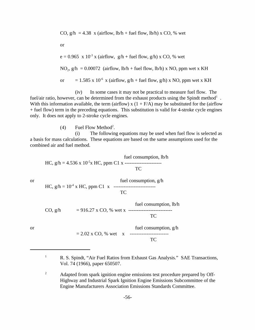
CO, g/h = 4.38 x (airflow, lb/h + fuel flow, lb/h) x CO, % wet
or
e = 0.965 x 10⁻³ x (airflow, g/h + fuel flow, g/h) x CO, % wet
NO , g/h = 0.00072 (airflow, lb/h + fuel flow, lb/h) x NO, ppm wet x KH2
or = 1.585 x 10⁻⁶ x (airflow, g/h + fuel flow, g/h) x NO, ppm wet x KH
(iv) In some cases it may not be practical to measure fuel flow. The fuel/air ratio, however, can be determined from the exhaust products using the Spindt method1 . With this information available, the term (airflow) x (1 + F/A) may be substituted for the (airflow + fuel flow) term in the preceding equations. This substitution is valid for 4-stroke cycle engines only. It does not apply to 2-stroke cycle engines.
(4) Fuel Flow Method2. (i) The following equations may be used when fuel flow is selected as
a basis for mass calculations. These equations are based on the same assumptions used for the combined air and fuel method.
fuel consumption, lb/h HC, g/h = 4.536 x 10⁻²x HC, ppm C1 x ----------------------
TC
or fuel consumption, g/h HC, g/h = 10-4 x HC, ppm C1 x -------------------------
TC
fuel consumption, lb/h CO, g/h = 916.27 x CO, % wet x --------------------------
TC
or fuel consumption, g/h = 2.02 x CO, % wet x -----------------------
TC
1 R. S. Spindt, “Air Fuel Ratios from Exhaust Gas Analysis.” SAE Transactions, Vol. 74 (1966), paper 650507.
2 Adapted from spark ignition engine emissions test procedure prepared by Off-Highway and Industrial Spark Ignition Engine Emissions Subcommittee of the Engine Manufacturers Association Emissions Standards Committee.
-56-

NO , g/h = 15.06 x 10⁻² x NO, ppm wet x KH x fuel consumption, lb/h2
-----------------------TC
or fuel consumption, g/h = 3.32 x 10⁻⁴ NO, ppm wet x KH x ----------------------
TC where:
TC = total carbon = vol % CO2 wet + vol % CO wet + vol % HC wet
(5) Fuel Flow Method - General equations for any fuel.
M = M + " x M + $ x MHC-exh C H O
HC (g/hr) = MHC-exh/MF x GFUEL/TC x vol % HC wet
CO (g/hr) = MCO/MF x GFUEL/TC x vol % CO wet
NOx (g/hr) = MNOx/MF x GFUEL/TC x vol % NOx wet/104 x KH
KH = 1/[1 - 0.0329 x (H-10.71)]
where:
MHC-exh = the molecular weight of hydrocarbons in the exhaust, as determined by the above equation.
MC = the molecular weight of Carbon = 12.01
MH = the molecular weight of Hydrogen = 1.008
MO = the molecular weight of Oxygen =16.00
" = the Hydrogen to Carbon ratio of the test fuel
$ = the Oxygen to Carbon ratio of the test fuel
MF = the molecular weight of the test fuel
MCO = the molecular weight of Carbon Monoxide = 28.01
-57-

MNOx = the molecular weight of Nitrogen Dioxide = 46.01
GFUEL = the fuel mass flow rate
TC = total carbon = vol % CO2 wet + vol % CO wet + vol % HC wet
KH = the factor for correcting the effects of humidity on NO2 formation for small four-stroke gasoline engines (for two-stroke gasoline engines, KH should be set to 1).
H = the specific humidity of the intake air in grams of moisture per kilogram of dry air.
-58-

- -
APPENDIX A
(a) When FID (flame ionization detector) is used in HC analysis and a chemiluminescent analyzer utilizing a wet sample is used for NO analysis, the combustion water is not removed and therefore measurements are made with reference to the wet exhaust. When NDIR and chemiluminescent analyzer requiring a dry sample are used for species analysis, water vapor is removed prior to the concentration measurement and the results are on a dry basis. The following equation may be used to determine the correction factor to be used in converting dry measurements to a wet basis.
1 K= -------------------------------------------
1+0.005 x (CO%+CO %) x y-(0.01 x H ) 2 2
where:
0.5 x y x CO% x (CO%+CO %)2
H2 = -------------------------------CO%+(3 x CO2 %)
y = H/C ratio of test fuel
Therefore: Species concentration, wet= K x species concentration, dry
For two-stroke cycle engines, we assume no residual free H2 and modify K by deleting the H2
term.
(b) The above method does not include a correction for air humidity. The humidity contribution to the exhaust is small and may be neglected. If it is desired to include the effects of humidity, Appendix C gives the derivation of a general equation which that may be used to determine the correction factor.
-59-

APPENDIX B
Derivation of Equations used for Air and Fuel Flow Method of Mass Conversion
Hydrocarbons - The exhaust unburned HC is assumed to have an average hydrogen-to-carbon ratio of 1.85/1 and a molecular weight of 13.85.
13.85 HC, g/h = (airflow,lb/h+fuel flow, lb/h) x -----------
mol wt exh
x HC,ppm C1 x 10-6 x 453.6 g/lb
0.00629 HC, g/h= ----------------- x (airflow,lb/h+fuel flow, lb/h) x HC,ppm C1
mol wt exh
Carbon Monoxide- CO has a molecular weight of 28.
28 CO, g/h= (airflow,lb/h+fuel flow, lb/h) x ------------
mol wt exh
x CO,%wet x 10-2x 453.6 g/lb
127.00 CO, g/h= (airflow,lb/h+fuel flow, lb/h) x -------------- x CO,%wet
mol wt exh
Nitrogen Dioxide- In accordance with present practice, NOx mass determinations are made in terms of NO2. Molecular weight of NO2 is 46.
46 NO2 , g/h= (airflow,lb/h+fuel flow, lb/h) x ---------------
mol wt exh
x NO,ppm wet x 10-6 x 453.6 g/lb x KH
0.02087 NO2 , g/h= (airflow,lb/h+fuel flow, lb/h) x --------------- x NO,ppm wet x KH
mol wt exh
-60-

Exhaust Molecular Weight- The following equation may be used to determine the molecular weight of the exhaust:
13.88 x HC ppm C1 28.01 x CO% mol wt exh= ------------------------- + ----------------
106 102
44.01 x CO2 % 46.00 x NOx ppm 32.00 x O2 % + ------------ + ------------------ + ------------------
2 6 210 10 10
2.016 x H %2
+ --------------- + 18.01 x (1-K) + [28.01 x (100 102
HC ppm C1 NO - --------------- - CO%- CO % - ---------- - O % - 100 x (1-K))]/102
2 2
104 104
For 2-stroke engines, we assume no residual free H2 and modify K by deleting the H2 term.
-61-

APPENDIX C
(a) This appendix outlines the development of the correct factor for converting dry data to a wet basis, accounting for the effect of both humidity and combustion water.
(b) Combustion in a gasoline engine can be approximated by the general equation:
CHy + nO2 + 3.76nN2 + mH O-->aCO + CO2 2 + cCH3 + dNO + eO2
+ fN + (g + m)H O + kH 2 2 2
where: a d g
n=moles of oxygen in air to engine = --- + b + --- + e + ---2 2 2
y=atoms of hydrogen per carbon atom = 3c + 2g + 2k
d f=moles of N2 = 3.76n - ---
2
m=moles of water in 4.76n moles of air
Mass of fuel per unit time:
F = 12.01 + 1.008y
Mass of wet air per unit time:
A = 32n + 105.28n + 18.016m
Then: 12.01 + 1.008y
F/A = ---------------------------137.28n + 18.016m
If specific humidity is measured in terms of grains/pound of dry air, h, then the pounds of water in 137.28n pounds of dry air is:
137.28n x 0.000143 lb/grain x h = 1.964 x 10⁻² nh, lb H O 2
This must be equal to 18.016m in the equations; therefore:
-62-

---------------------------
12.01 + 1.008y F/A = ------------------------ x 10-2 nh or
137.28n + 1.964
12.01 + 1.008y
n(137.28n + 1.964 x 10⁻² h)
-2 -3and m = 1.964 x 10 nh/18.016 or 1.09 x 10 nh
If F and A are measured, then n can be calculated from:
12.01 + 1.008y n = (A/F) x ------------------------
137.28 + 1.964 x 10⁻³ h
Volume fraction of water in exhaust:
g + m W = --------------------------------------------
a + b + c + d + e + f + k + g + m
But:
d f = 3.76n - ---
2
a d g n = -- + b + -- + e + --
2 2 2
Substituting and collecting:
g+m W = ---------------------------------------
a g -- + c + -- + m + k + 4.76n 2 2
y - 3c - 2k But: g = -------------- and c = 1 - a - b
2
-63-

Therefore:
y - 3(1 - a - b) - 2k ------------------------- + m
2 W = -------------------------------------------------------------
y - 3(1 - a - b) - 2k a --------------------------- + 1 - a - b + -- + m + k + 4.76n
4 2
y - 3(1 - a - b) - 2k -------------------------- + m
2 W = -------------------------------------------------
y + 1 + a - b + 2k ----------------------------- + m + 4.76
4 Substituting for m
y - 3(1 - a - b) - 2k -------------------------- + 1.09 x 10⁻³ nh
2 W = ---------------------------------------------------------
y + 1 + a - b + 2k --------------------------- + n(4.76 + 1.09 x 10⁻³ h)
4 The correction factor to be applied to the dry gas values, then, is
CF = 1 - W
(c) On the lean side of stoichiometric, the amount of free hydrogen in the exhaust is small and k can be dropped. On the rich side, however, the hydrogen content can be appreciable. One source from which an estimate of the free hydrogen in the exhaust can be obtained is Chapter 10 of “Internal Combustion Engines” by E. F. Obert. It should be noted that the measured exhaust data cannot be directly substituted in the above equation. A combustion equation must be written in the form of the general equation at the beginning of this Appendix to determine the numerical values of a, b, y, and k.
(d) An alternative approach to that presented above in this Appendix is given in SAE ARP 1256, issued January 10, 1971, revised January 8, 1990 and incorporated by reference herein.
-64-

- -
Part III IV . Spark-Ignition Engines - Constant Volume Sampling Test Procedures
1. [Reserved].
2. Exhaust Gas Sampling System.
(a) (1) General. The exhaust gas sampling system is designed to measure the true mass emissions of engine exhaust. In the CVS concept of measuring mass emissions, two conditions must be satisfied: the total volume of exhaust and dilution air must be measured and a continuously proportioned volume of sample must be collected for analysis. Mass emissions are determined from the sample concentration and totalized flow over the test period.
(2) [Reserved]. (3) Positive Displacement Pump. The positive displacement pump- constant
volume sample (PDP-CVS), Figure F90-1, satisfies the first condition by metering at a constant temperature and pressure through the pump. The total volume is measured by counting the revolutions made by the calibrated positive displacement pump. The proportional sample are achieved by sampling at a constant flow rate.
(4) Critical Flow Venturi. The operation of the Critical Flow Venturi-Constant Volume Sampler (CFV-CVS), Figure F90-2, is based upon the principles of fluid dynamics associated with critical flow. Proportional sampling is maintained by use of small CFVs in the sample lines, which that responds to the varying temperatures in the same manner as the main CFV.
(5) [Reserved]. (6) Other systems. Other sampling systems may be used if shown to yield
equivalent, and if approved by the Executive Officer (e.g., a heat exchanger with the CFV-CVS or an electronic flow integrator without a heat exchanger, with the PDP-CVS).
(b) Component description, PDP-CVS. The PDP-CVS, Figure F90-1, consists of a dilution air filter and mixing assembly, heat exchanger, positive displacement pump, sampling systems including, probes and sampling lines and associated values, pressure and temperature sensors. The PDP-CVS shall must conform to the following requirements. - -
(1) Static pressure variations at the exhaust of the engine shall must remain within +/- 1.25 kPa (+/- 5.02 in. H O) of the static pressure variations measured during a dynamometer2
cycle with no connection to the exhaust. (Sampling systems capable of maintaining the static pressure to within +/- 0.25 kPa (+/- 1.00 in. H O) will be used by the Executive Officer if a2
written request substantiates the need for this closer tolerance.) (2) The gas mixture temperature, measured at a point immediately ahead of the
o opositive displacement pump, shall must be within +/- 5 C (9 F) during the entire test. The o otemperature measuring system shall must have an accuracy and precision of +/- 1 C (1.8 F).
(3) The pressure gauges shall must have an accuracy and precision of +/- 0.4 kPa (+/- 3 mm Hg).
-65-

(4) The location of the dilution air inlet shall must be placed so as to use test-cell air for dilution air and the flow capacity of the CVS shall must be large enough to eliminate water condensation in the system.
AM
BIE
NT
AIR
SA
MP
LE B
AG
PO
SIT
IVE
DIS
PLA
CE
ME
NT
EX
CH
AN
GE
PR
EM
LAT
ER
M
AN
OM
ET
ER
SY
MB
OL
LEG
EN
D
CO
OLA
NT
RE
VO
LUT
ION
DX
] FLO
W C
ON
TR
OL
VA
LVE
P
ICK
UP
SE
LEC
TIO
N V
ALV
EX
]
7 P
AR
TIC
ULA
TE
Fat
ER
D
ISC
HA
RG
E
FLO
WM
ET
ER
PR
ES
SU
RE
GA
UG
E
TE
MP
ER
AT
UR
E S
EN
SO
R
FIG
UR
E F
90-1
: Exh
aust
Gas
Sam
plin
g S
yste
m (
PD
P-C
VS
).
-66-

- -
UH
LUT
ION
AI
SA
MP
LIN
G V
EN
TU
RI
SA
MP
LE B
AG
CY
CLO
NIC
SE
PA
RA
TO
R
- A
BS
OLU
TE
PR
ES
SIM
ME
TR
AN
SD
UC
ER
CR
ITIC
AL
PR
EC
ISIO
N S
EN
SO
R
CV
S C
OM
PR
ES
SO
R U
NIT
CV
S S
AM
PLE
R L
IMIT
ST
MB
OL
LEG
EN
O
BLO
WE
R
DK
SE
LEC
TIO
N W
ALK
PA
RT
KU
RA
IL F
US
E
ISC
HA
RG
E Q
Put
er
FIG
UR
E F
50-2
:
PR
ES
SU
RE
GA
UG
E
XH
AU
ST
GA
S S
AM
PLI
NG
SY
ST
EM
(C
FV
.CV
S)
1 R
EC
OR
DE
R
TE
MP
ER
AT
E S
E
(5) Sample collection bags for dilution air and exhaust samples shall must be of sufficient size so as to not impede sample flow.
(c) Component description, CFV-CVS. The CFV-CVS, Figure F90-2, consists of a dilution air filter and mixing assembly, cyclone particulate separator, unheated sampling venturies for the bag, critical flow venturi, and assorted valves, pressure and temperature sensors. The CFV-CVS shall must conform to the following requirements.
-67-
10

- -
(1) Static pressure variations at the exhaust of the engine shall must remain within +/- 1.25 kPa (+/- 5.02 in. H O) of the static pressure variations measured during a dynamometer
- - 2
driving cycle with no connection to the exhaust. (Sampling systems capable of maintaining the static pressure to within +/- 0.25 kPa (+/- 1.00 in. H O) will be used by the Executive Officer if a2
written request substantiates the need for this closer tolerance.) (2) The temperature measuring system shall must have an accuracy and precision
o oof +/- 1 C (1.8 F) and a response time of 0.100 second to 62.5 percent of a temperature change (as measured in hot silicone oil).
(3) The pressure measuring system shall must have an accuracy and precision of +/- 0.4 kPa (+/- 3 mm Hg).
(4) The location of the dilution air inlet shall must be placed so as to use test-cell air for dilution air and the flow capacity of the CVS shall must be large enough to eliminate water condensation in the system.
(5) Sample collection bags for dilution air and exhaust samples shall must be of sufficient size so as to not impede sample flow.
3. Exhaust Gas Analytical System.
(a) Schematic Drawings. Figure F90-3 is a schematic drawing of the exhaust gas analytical system for analysis of hydrocarbons (HC),- - carbon monoxide (CO), carbon dioxide (CO )2 , and oxides of nitrogen (NOx). Since various configurations can produce accurate results, exact conformance with the drawing is not required. Additional components such as instruments, valves, solenoids, pumps and switches may be used to provide additional information and coordinate the functions of the component systems.
(b) Major component description. The exhaust gas analytical system for HC, CO and CO , Figure F90-3, consists of a flame ionization detector (FID) for the determination of2
hydrocarbons, nondispersive infrared analyzers (NDIR) for the determination of carbon monoxide and carbon dioxide, and a chemiluminescence analyzer (CL) for the determination of oxides of nitrogen. The exhaust gas analytical system shall must conform to the following requirements. - -
(1) The CL requires that the nitrogen dioxide present in the sample be converted to nitric oxide before analysis. Other types of analyzers may be used if shown to yield equivalent results and if approved in advance by the Executive Officer.
(2) The carbon monoxide (CO) NDIR analyzer may require a sample conditioning column containing CaSO , or indicating silica gel to remove water vapor and4
containing ascarite to remove carbon dioxide from the CO analysis stream. (i) If CO instruments which that are essentially free of CO2 and water
vapor interference are used, the use of the conditioning column may be deleted, see Sections 11 and 26.
(ii) A CO instrument will be considered to be essentially free of CO2
and water vapor interference if its response to a mixture of 3 percent CO2 in N2 which that has been bubbled through water at room temperature produces an equivalent CO response, as measured on the most sensitive CO range, which that is less than 1 percent of full scale CO
-68-

concentration on ranges above 300 ppm full scale or less than 3 ppm on ranges below 300 ppm full scale; see Section 11.
(c) Other analyzers and equipment. Other types of analyzers and equipment may be used if shown to yield equivalent results and if approved in advance by the Executive Officer.
-69-

FUEL AIR
EXPO ZERO HC
GASES
HIGH CO
CONDITION COLUMNS
LOW COSPAN GASES
MANIFOLD
SAMPLE
CO
GASES
DO GAS
SYMBOL LEGEND GASESDOW CONTROL VALVE
SELECTION VALVE TO OUTSIDE VENT PARTICULATE PATER
PUMP
FLOWMETER PRESSURE GAUGE
RECORDER
TEMPERATURE SENSOR
FIGURE F90-3: Exhaust Gas Analytical System
-70-

- -
4. Engine Fuel and Lubricant Specifications.
(a) Engine Fuel Specifications. (1) Certification Fuels.
(i) Petroleum-based fuels. The certification test fuel used for emission testing shall must be consistent with the fuel specifications as outlined in the California Code of Regulations, Title 13, Section 1960.1, and the latest amendment of the “California Exhaust Emission Standards and Test Procedures for 1988 and Subsequent Model Passenger Cars, Light-Duty Trucks, and Medium-Duty Vehicles”, incorporated by reference herein. The test fuel specification should remain consistent from batch to batch. If a particular engine requires a different octane (or cetane) fuel, test records should indicate the fuel used.
(ii) Alcohol-based fuels. Alcohol-based fuels shall will be allowed for emission test purposes when the appropriate emission standards with respect to such fuels are a part of these provisions. Such fuels shall must be as specified in subparagraph (a)(1)(i) above.
(2) Service Accumulation Fuels. (i) Gasoline.
(A) The engine manufacturer has the option to use a gasoline that satisfies the same fuel specifications as any of the certification test gasolines, or unleaded gasoline representative of commercial gasoline which that will be generally available through retail outlets shall must be used in service accumulation for gasoline-fueled otto-cycle engines. Leaded fuel shall must not be used during service accumulation.
- -
(B) The octane rating of the gasoline used shall must be no higher than 4.0 Research Octane Numbers above the minimum recommended by the engine manufacturer when a certification fuel is not used for service accumulation, and shall must have a minimum sensitivity of 7.5 octane numbers. Sensitivity is the Research Octane Number minus the Motor Octane Number.
(C) The Reid Vapor Pressure of a gasoline shall must be characteristic of the engine fuel during the season in which the service accumulation takes place in the outdoors, or shall must be characteristic of the engine fuel appropriately suited to the ambient conditions of an indoor test cell in which the entire service accumulation takes place.
- -
(ii) Diesel fuel. (A) As specified in subparagraph (a)(1)(i) of this Section.
(iii) Alternative fuels. (A) As specified in subparagraph (a)(1)(i) of this Section.
Liquefied petroleum gas meeting the ASTM D1835 (November 10, 1997) or NGPA HD-5 (in NGPA Publication 2140-70, 1970) specifications must be used for service accumulation.
(B) Natural gas representative of commercial natural gas that is available locally to the manufacturer’s test site may be used in service accumulation. The manufacturer must provide the Executive Officer with details of how the commercial natural gas differs from the certification test fuel specifications.
-71-

- -
(b) Engine Lubrication. (1) Certification Test Lubricants.
(i) Engines shall must use the lubricants specified by the engine manufacturer.
(ii) Two-stroke engines shall must use the fuel-oil mixture ratio specified by the engine manufacturer. Emission compliance shall must be demonstrated for each fuel-oil mixture ratio that is recommended to the ultimate purchaser.
(2) Service Accumulation Lubricants. (i) Engine lubricants that are representative of commercially available
engine lubricants shall must be used in the engine service accumulation.
5. Analytical Gases.
(a) Analyzer gases. (1) Calibration or span gases for the CO and CO2 analyzers shall must be single
blends of CO and CO2 respectively using nitrogen as the diluent. (2) Calibration or span gases for the hydrocarbon analyzer shall must be single
blends of propane using air as the diluent. (3) Calibration or span gases for NOx analyzer shall must be single blends of
NO named as NOx with a maximum NO2 concentration of 5 percent of the nominal value using nitrogen as the diluent.
(4) [Reserved]. (5) The allowable zero-grade gas (air or nitrogen) impurity concentrations
shall must not exceed 1 ppm equivalent carbon response, 1 ppm carbon monoxide, 0.04 percent (400 ppm) carbon dioxide, and 0.1 ppm nitric oxide.
(6) “Zero-grade air” includes artificial “air” consisting of a blend of nitrogen and oxygen with oxygen concentrations between 18 and 21 mole percent.
(7) The use of proportioning and precision blending devices (i.e., gas dividers) to obtain the required analyzer gas concentrations is allowed provided such devices are maintained in accordance with the instructions of the device manufacturer.
(b) Calibration gas. (1) Calibration gas values are to be derived from the National Institute for
Standards and Technology's (NIST's) “Standard Reference Materials” (SRM's), and are to be single blends as follows.
(i) Mixtures of gases that have the following chemical compositions shall must be available: C H and zero-grade air; CO and zero-grade nitrogen; NOx and3 8
zero-grade nitrogen (the amount of NO2 contained in this calibration must not exceed 5 percent of the NO content); and, CO2 and zero-grade nitrogen.
(ii) The true concentration of a span gas must be within +/- 2 percent of the NIST gas standard. The true concentration of a calibration gas must be within +/- 1 percent of the NIST gas standard. All concentrations of calibration gas shall must be given on a volume basis (volume percent or volume ppm).
-72-

- - - -
(iii) When the gas concentration used for calibration and span is obtained by means of a gas divider the gas concentration shall must be diluted with either zero-grade N2 or zero-grade air (as applicable). The accuracy of the diluted gases may be determined to within +/- 2 percent.
(iv) Fuel for the FID detector shall must be a blend of 40 +/- 2 percent hydrogen with the balance as helium. The mixture must contain less than 1 ppm equivalent carbon response; 98 to 100 percent hydrogen fuel may be used with advance approval of the Executive Officer.
(v) Oxygen interference check gases must contain propane with 350 +/-75 ppmC hydrocarbon. The concentration value to calibration gas tolerances shall must be determined by chromatographic analysis of total hydrocarbons plus impurities, or by dynamic blending. Nitrogen must be the predominant diluent with the balance oxygen.
(vi) Hydrocarbon analyzer burner air. The concentration of oxygen must be within 1 mole percent of the oxygen concentration of the burner air used in the latest oxygen interference check (percent O I). If the difference in oxygen concentration is greater than2
1 mole percent, the oxygen interference must be checked and the analyzer adjusted (as necessary) to satisfy the percent O I requirements. The burner air must contain less than 2 ppmC2
hydrocarbon.
6. [Reserved].
7. Calibrations, Frequency and Overview.
(a) Calibrations shall must be performed as specified in Sections 8 through 14.
(b) [Reserved].
(c) At least monthly or after any maintenance which that could alter calibration, the following calibrations and checks shall must be performed:
(1) Calibrate the hydrocarbon analyzer, carbon dioxide analyzer, carbon monoxide analyzer, and oxides of nitrogen analyzer (certain analyzers may require more frequent calibration depending on particular equipment and uses).
(2) Calibrate the dynamometer as specified in Section 8.
(d) At least weekly, or after any maintenance which that could alter calibration, a CVS system verification check shall must be performed. - -
(e) The CVS positive displacement pump or critical Flow Venturi shall must be calibrated following initial installation, major maintenance or as necessary when indicated by the CVS system verification (described in Section 9).
-73-

(f) Sample conditioning columns, if used in the CO analyzer train, should be checked at a frequency consistent with observed column life or when the indicator of the column packing begins to show deterioration.
8. Dynamometer Calibration.
(a) The dynamometer shall must be calibrated at least once each month using the dynamometer manufacturer's method of calibration. If required by the dynamometer manufacturer, the dynamometer shall must be performance verified at least once each week, and then calibrated accordingly.
9. Constant Volume Sampler Calibration.
(a) The CVS (Constant Volume Sampler) is calibrated using an accurate flowmeter and restrictor valve. Measurements of various parameters are made and related to flow through the unit. Procedures used by ARB for both PDP (Positive Displacement Pump) and CFV (Critical Flow Venturi) are outlined below. Other procedures yielding equivalent results may be used if approved in advance by the Executive Officer. After the calibration curve has been obtained, verification of the entire system can be performed by injecting a known mass of gas into the system and comparing the mass injected. An indicated error does not necessarily mean that the calibration is wrong, since other factors can influence the accuracy of the system, e.g., analyzer calibration. A verification procedure is found in paragraph (d) of this Section.
(b) PDP calibration. (1) The following calibration procedure outlines the equipment, the test configuration, and the various parameters which that must be measured to establish the flow rate of the constant volume sampler pump. All of the parameters related to the pump are simultaneously measured with the parameters related to a flowmeter which that is connected in series with the pump. The calculated flow rate (at pump inlet absolute pressure and temperature) can then be plotted versus a correlation function which that is the value of a specific combination of pump parameters. The linear equation which that relates the pump flow and the correlation function is then determined. In the event that a CVS has a multiple speed drive, a calibration for each range must be performed.
(2) This calibration procedure is based on the measurement of the absolute values of the pump and flowmeter parameters that relate the flow rate at each point. Three conditions must be maintained to assure the accuracy and integrity of the calibration curve. First, the pump pressures should be measured at taps on the pump rather than at the external piping on the pump inlet and outlet. Pressure taps that are mounted at the top center and bottom center of the pump drive headplate are exposed to the actual pump cavity pressures, and therefore reflect the absolute pressure differentials. Secondly, temperature stability must be maintained during the calibration. The laminar flowmeter is sensitive to inlet temperature oscillations which that cause
o othe data points to be scattered. Gradual changes (+/-1 C [+/-1.8 F]) in temperature are acceptable as long as they occur over a period of several minutes. Finally, all connections between the flowmeter and the CVS pump must be absolutely void of any leakage.
-74-

(3) During an exhaust emission test the measurement of these same pump parameters enables the user to calculate the flow rate from the calibration equation.
(4) Connect a system as shown in Figure F78-5. Although particular types of equipment are shown, other configurations that yield equivalent result may be used if approved in advance by the Executive Officer. Table 3-1 Calibration Data Measurements lists the data required (with accuracy) for the indicated system.
(5) After the system has been connected as shown in Figure F78-6, set the variable restrictor in the wide open position and run the CVS pump for twenty minutes. Record the calibration data.
(6) Reset the restrictor valve to a more restricted condition in an increment of pump inlet depression (about 1.0 kPa (4 in. H 0)) that will yield a minimum of six data points for2
the total calibration. Allow the system to stabilize for 3 minutes and repeat the data acquisition. (7) Data analysis.
(i) The air low rate, Q , at each test point is calculated from thes
flowmeter data using the manufacturers' prescribed method. (ii) The air flow rate is then converted to pump flow, Vo in m3 per
revolution at absolute pump inlet temperature and pressure.
V = (Q /n) X (T /293) X (101.3/P ) o s p p
Where: 3 3(A) V = Pump flow, m /rev (ft /rev) at T , P o p p
(B) Qs = Meter air flow rate in standard cubic meters per minute; standard conditions o oare 20 C, 101.3 kPa (68 F, 29.92 in. Hg.).
(C) n = Pump speed in revolutions per minute. o(D) (1) Tp = Pump inlet temperature, ( K) = PTI + 273.
(2) For English units, Tp = PTI + 460. (E) (1) Pp = Absolute pump inlet pressure, kPa (in.Hg) = PB - PPI.
(2) For English units, Pp = PB - PPI(SP.GR./13.57).
-75-

Table 3-1. Calibration Data Measurements
Parameter Sym. Units Tolerances
Barometric pressure corrected PB kPa (in. Hg) ± 0.03 kPa (± 0.01 in. Hg
Ambient temperature TA o oC ( F) o o± 0.3 C (± 0.54 F)
Air Temperature into LFE ETI o oC ( F) o o± 0.15 C (± 0.27 F)
Pressure depression upstream of LFE EPI kPa (in. H O) 2 ± 0.01kPa (± 0.05 in. H O) 2
Pressure drop across the LFE matrix EDP kPa (in. H O) 2 ± 0.001kPa (± 0.005 in. H O)2
Air temperature at CVS pump inlet PTI o oC ( F) o o± 0.25 C (± 0.45 F)
Pressure depression at CVS pump inlet
PPI kPa. (in. Fluid) ± 0.021kPa (±0.046 in. Fluid)
Specific gravity of manometer fluid (1.75 oil)
Sp. Gr.
Pressure head at CVS pump outlet PPO kPa. (in. Fluid) ± 0.021kPa (±0.046 in. Fluid)
Air temperature at CVS pump outlet (optional)
PTO o oC ( F) o o± 0.25 C (± 0.45 F)
Pump revolutions during test period N Revolutions ± 1 revolution
Elapsed time for test period t seconds ± 0.05 seconds
Where: (F) PB = barometric pressure, kPa (in.Hg.). (G) PPI = Pump inlet depression, kPa (in.fluid). (H) SP.GR.= Specific gravity of manometer fluid relative to water.
-76-
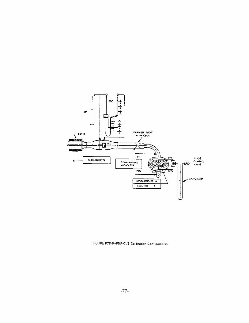
EM
LULLLI VARIABLE FLOW
- FILTER RESTRICTOR
SURGE THERMOMETER
TEMPERATURE CONTROL INDICATOR VALVE
PIO
MANOMETER REVOLUTIONS N SECONDS
FIGURE F78-5--PDP-CVS Calibration Configuration.
-77-

TILLLA SAMPLER DUCT
VALVE
FIGURE F78-6: CFV-CVS Calibration Configuration.
OPERATING RANGE
KY
INLET DEPRESSION
FIGURE F78-7:-Sonic Flow Choking.
-78-

(iii) The correlation function at each test point is then calculated from the calibration data:
X = 1/n (ÎP /P )-2 d P e
Where. (A) X = correlation function. (B) ÎP
o
p = The pressure differential from pump inlet to pump outlet, kPa (in.Hg) = Pe - Pp.
(C) (1) Pe = Absolute pump outlet pressure, kPa(in.Hg) = PB + PPO. (2) For English units, Pe = PB + PPO(SP.GR./13.57).
Where: (D) PPO = Pressure head at pump outlet, kPa (in.fluid).
(iv) A linear least squares fit is performed to generate the calibration equations which that have the forms:
V = D - M(X ) o o o
n = A - B(ÎP )p
Do , M, A, and B are the slope-intercept constants, describing the lines.
(8) CVS system that has multiple speeds shall must be calibrated on each speed used. The calibration curves generated for the ranges will be approximately parallel and the intercept values, D will increase as the pump flow range decreases.
(9) If the calibration has been performed carefully, the calculated values from the equation will be within +/-0.50 percent of the measured value of Vo Values of M will vary from one pump to another, but values of Do for pumps of the same make, model, and range should agree within +/-3 percent of each other. Particulate influx from use will cause the pump slip to decrease as reflected by lower values for M. Calibrations should be performed at pump startup and after major maintenance to assure the stability of the pump slip rate. Analysis of mass injection data will also reflect pump slip stability.
(c) CFV calibration. (1) Calibration of the Critical Flow Venturi (CFV) is based upon the flow
equation for a critical venturi. Gas flow is a function of out pressure and temperature:
Q = K P/(T)-2 s v
Where: (i) Qs = Flow. (ii) Kv = Calibration coefficient. (iii) P = Absolute pressure.
-79-

(iv) T = Absolute temperature.
The calibration procedure described below establishes the value of the calibration coefficient at the measured values of pressure, temperature and air flow.
(2) The test equipment manufacturer's recommended procedure shall must be followed for calibrating electronic portions of the CFV.
(3) Measurements necessary for flow calibration are listed in Table 3-2 Calibration Data Measurements.
Table 3-2 Calibration Data Measurements
Parameter Sym. Units Tolerances
Barometric pressure corrected PB kPa (in. Hg) ± 0.03 kPa (± 0.01 in. Hg
Air Temperature, flowmeter ETI o oC ( F) o o± 0.15 C (± 0.27 F)
Pressure depression upstream of LFE EPI kPa (in. H O) 2 ± 0.01kPa (± 0.05 in. H O) 2
Pressure drop across the LFE matrix EDP kPa (in. H O) 2 ± 0.001kPa (± 0.005 in. H O)2
Air flow Qs 3 3m /min (ft /min) ± 0.5%
CVS inlet depression PPI kPa. (in. Fluid) ± 0.02kPa (±0.05 in. Fluid)
Specific gravity of manometer fluid (1.75 oil)
Sp. Gr.
Pressure head at CVS pump outlet PPO kPa. (in. Fluid) ± 0.021kPa (±0.046 in. Fluid)
Air temperature at venturi inlet Tv o oC ( F) o o± 0.25 C (± 0.45 F)
(4) Set up equipment as shown in Figure F78-6 and check for leaks. Any leaks between the flow measuring device and the critical flow venturi will seriously affect the accuracy of the calibration.
(5) Set the variable flow restrictor to the open position, start the blower and allow the system to stabilize. Record data from all instruments.
(6) Vary the flow restrictor and make at least 8 readings across the critical flow range of the venturi.
(7) Data analysis. The data recorded during the calibration are to be used in the following calculation.
(i) The air flow rate, Q , at each test point is calculated from thes
flowmeter data using the manufacturer's prescribed method.
-80-

(ii) Calculate values of the calibration coefficient for each test point:
K = Q (T -2) / Pv s v v
Where: 3 o(A) Qs = Flow rate in m /minute, standard conditions are 20 C,
o101.3 kPa (68 F, 29.92 in.Hg) o o(B) Tv = Temperature at venturi inlet, K( R).
(C) (1) Pv = Pressure at venturi inlet, kPa (mm Hg) = PB -PPI. For English units, Pv = PB - PPI(SP.GR./13.57).
(D) PPI = Venturi inlet pressure depression, kPa (in.fluid). (E) SP.GR. = Specific gravity of manometer fluid, relative to
water. (iii) Plot Kv as a function of venturi inlet depression. For sonic flow, Kv
will have a relatively constant value. As pressure decreases (vacuum increases), the venturi becomes unchoked and Kv decreases (is no longer constant). See Figure F78-7.
(iv) For a minimum of 8 points in the critical region, calculate an average Kv and the standard deviation.
(v) If the standard deviation exceeds 0.3 percent of the average Kv, take correction action.
(d) CVS system verification. The following “gravimetric” technique can be used to verify that the CVS and analytical instruments can accurately measure a mass of gas that has been injected into the system. If the CVS and analytical system will be used only in the testing of gasoline-fueled engines, the system verification may be performed using either propane or carbon monoxide. (Verification can also be accomplished by constant flow metering using critical flow orifice devices.)
(1) Obtain a small cylinder that has been charged with pure propane or carbon monoxide gas (caution-carbon monoxide is poisonous).
(2) Determine a reference cylinder weight to the nearest 0.01 grams. (3) Operate the CVS in the normal manner and release a quantity of pure propane
or carbon monoxide into the system during the sampling period (approximately 5 minutes). (4) The calculations of Section 26 are performed in the normal way except in the
3case of propane. The density of propane (0.6109 kg/m3 carbon atom (17.30 g/ft ) is used. (5) The gravimetric mass is subtracted from the CVS measured mass and then
divided by the gravimetric mass to determine the percent accuracy of the system. (6) The cause for any discrepancy greater than +/-2 percent must be found and
corrected.
10. Hydrocarbon Analyzer Calibration.
(a) The FID hydrocarbon analyzer shall must receive the following initial and periodic calibration.
-81-

(b) Initial and periodic optimization of detector response. Prior to its introduction into service and at least annually thereafter, the FID hydrocarbon analyzer shall must be adjusted for optimum hydrocarbon response. Alternate methods yielding equivalent results may be used, if approved in advance by the Executive Officer. For natural gas-fueled engines, the analyzer must be optimized using propane. The analyzer’s response factor for methane must be determined and accounted for in the measurements of total hydrocarbons. (See section (d).)
(1) Follow the analyzer manufacturer's instructions or good engineering practice for instrument startup and basic operating adjustment using the appropriate FID fuel and zero-grade air.
(2) Optimize on the common operating range. Introduce into the analyzer a propane in air mixture with a propane concentration equal to approximately 90 percent of the most common operating range.
(3) Select an operating FID fuel flow rate that will give near maximum response and least variation in response with minor fuel flow variations.
(4) To determine the optimum air flow, use the FID fuel flow setting determined above and vary air flow.
(5) After the optimum flow rates have been determined, record them for future reference.
(c) Initial and periodic calibration. Prior to its introduction into service and monthly thereafter the FID hydrocarbon analyzer shall must be calibrated on all normally used instrument ranges. Use the same flow rate as when analyzing sample.
(1) Adjust analyzer to optimize performance. (2) Zero the hydrocarbon analyzer with zero-grade air. (3) Calibrate on each normally used operating range with propane in air
calibration gases having nominal concentrations of 10, 20, 30, 40, 50, 60, 70, 80 and 90 percent of that range. For each range calibrated, if the deviation from a least squares best-fit straight line is 2 percent or less of the value at each data point, concentration values may be calculated by use of a single calibration factor for that range. If the deviation exceeds 2 percent at any point, the best-fit non linear equation which that represents the data to within 2 percent of each test point shall must be used to determine concentration.
(d) FID Response factor to methane. When the FID analyzer is to be used for the analysis of natural-gas fueled engine hydrocarbon samples, the methane response factor of the analyzer must be established. To determine the total hydrocarbon FID response to methane, known methane in air concentrations traceable to National Institute of Standards and Technology (NIST) must be analyzed by the FID. Several methane concentrations must be analyzed by the FID in the range of concentrations in the exhaust sample. The total hydrocarbon FID response to methane is calculated as follows:
r = FIDppm/SAMppmCH4 .
where:
-82-

- -
(1) rCH4 = FID response factor to methane. (2) FIDppm = FID reading in ppmC. (3) SAMppm = the known methane concentration in ppmC.III
11. Carbon Monoxide Analyzer Calibration.
(a) Initial and periodic interference check. Prior to its introduction into service and annually thereafter the NDIR carbon monoxide analyzer shall must be checked for response to water vapor and CO .
- -
(1) Follow the analyzer manufacturer's instruction for instrument startup and operation. Adjust the analyzer to optimize performance on the most sensitive range.
(2) Zero the carbon monoxide analyzer with either zero-grade air or zero-grade nitrogen.
(3) Bubble a mixture of 3 percent CO2 in N2 through water at room temperature and record analyzer response.
(4) An analyzer response of more than 1 percent of full scale for ranges above 300 ppm full scale or of more than 3 ppm on ranges below 300 ppm full scale will require corrective action. (Use of conditioning columns is one form of corrective action which that may be taken.)
(b) Initial and periodic calibration. Prior to its introduction into service and monthly thereafter the NDIR carbon monoxide analyzer shall must be calibrated. - -
(1) Adjust the analyzer to optimize performance. (2) Zero the carbon monoxide analyzer with either zero-grade air or zero-grade
nitrogen. (3) Calibrate on each normally used operating range with carbon monoxide in N2
calibration gases having nominal concentrations of 10, 20, 30, 40, 50, 60, 70, 80 and 90 percent of that range. Additional calibration points may be generated. For each range calibrated, if the deviation from a least-squares best-fit straight line is 2 percent or less of the value at each data point, concentration values may be calculated by use of a single calibration factor for that range. If the deviation exceeds 2 percent at any point, the best-fit non-linear equation which that represents the data to within 2 percent of each test point shall must be used to determine concentration.
12. Oxides of Nitrogen Analyzer Calibration.
(a) Prior to its introduction into service and monthly thereafter the chemiluminescent oxides of nitrogen analyzer shall must be checked for NO2 to NO converter efficiency. Figure F78-8 is a reference for the following steps.
- -
(1) Follow the analyzer manufacturer's instructions for instrument startup and operation. Adjust the analyzer to optimize performance.
(2) Zero the oxides of nitrogen analyzer with zero-grade air or zero-grade nitrogen.
-83-

- -
(3) Connect the outlet of the NOx generator to the sample inlet of the oxides of nitrogen analyzer which that has been set to the most common operating range.
(4) Introduce into the NOx generator analyzer-system a NO in nitrogen (N )2
mixture with a NO concentration equal to approximately 80 percent of the most common operating range. The NO2 content of the gas mixture shall must be less than 5 percent of the NO concentration.
(5) With the oxides of nitrogen analyzer in the NO mode, record the concentration of NO indicated by the analyzer.
(6) Turn on the NOx generator O2 (or air) supply and adjust the O2 (or air) supply flow rate so that the NO indicated by the analyzer is about 10 percent less than indicated in step 5. Record the concentration of NO in this NO+O2 mixture.
(7) Switch the NOx generator to the generation mode and adjust the generation rate so that the NO measured on the analyzer is 20 percent of that measured in step 5. There must be at least 10 percent unreacted NO at this point. Record the concentration of residual NO.
(8) Switch the oxides of nitrogen analyzer to the NOx mode and measure total NOx. Record this value.
(9) Switch off the NOx generation but maintain gas flow through the system. The oxides of nitrogen analyzer will indicate the NO in the NO+O2 mixture. Record this value.
(10) Turn off the NOx generator O2 (or air) supply. The analyzer will now indicate the NOx in the original NO in N2 mixture. This value should be no more than 5 percent above the value indicated in step 4.
(11) Calculate the efficiency of the NOx converter by substituting the concentrations obtained into the following equation:
Percent Efficiency={1+(a-b)/(c-d)}x100
where:
a=concentration obtained in step (8). b=concentration obtained in step (9). c=concentration obtained in step (6). d=concentration obtained in step (7).
If converter efficiency is not greater than 90 percent corrective action will be required.
(b) Initial and periodic calibration. Prior to its introduction into service and monthly thereafter, if oxides of nitrogen are measured, the chemiluminescent oxides of nitrogen analyzer shall must be calibrated on all normally used instrument ranges. Use the same flow rate as when analyzing samples. Proceed as follows.
(1) Adjust analyzer to optimize performance. (2) Zero the oxides of nitrogen analyzer with zero-grade air or zero-grade
nitrogen.
-84-

(3) Calibrate on each normally used operating range with NO in N2 calibration gases with nominal concentrations of 50 and 100 percent of that range. Additional calibration points may be generated.
FLOW CONTROL OLENOID VALVE
Of OR AIR SUPPLY
15 V.A.C.
VARIAC
OZONATOR
NO/N; SUPPLY
-DK
ANALYZER
CONNECTOR
ISEE FIG F90-3 FOR SYMBOL LEGENDI
FIGURE F78-8: . NOx Converter Efficiency Detector.
-85-

13. Carbon Dioxide Analyzer Calibration.
(a) Prior to its introduction into service and monthly thereafter the NDIR carbon dioxide analyzer shall must be calibrated.
(1) Follow the analyzer manufacturer's instructions for instrument startup and operation. Adjust the analyzer to optimize performance.
(2) Zero the carbon dioxide analyzer with either zero-grade air or zero-grade nitrogen.
(3) Calibrate on each normally used operating range with carbon dioxide in N2
calibration gases with nominal concentrations of 10, 20, 30, 40, 50, 60, 70, 80 and 90 percent of that range. Additional calibration points may be generated. For each range calibrated, if the deviation from a least-squares best-fit straight line is 2 percent or less of the value at each data point, concentration values may be calculated by use of a single calibration factor for that range. If the deviation exceeds 2 percent at any point, the best-fit non-linear equation which that represents the data to within 2 percent of each test point shall must be used to determine concentration.
14. Calibration of Other Equipment.
Other test equipment used for testing shall must be calibrated as often as required by the manufacturer or as necessary according to good practice.
15. Test Procedures, Overview.
(a) The appropriate six-mode test cycle for non-handheld equipment engines greater than 65 cc displacement volume, and the appropriate two-mode test cycle for handheld equipment engines less than or equal to 65 cc displacement volume, shall must be utilized (See Table 1-1 Engine Test Cycles; Part I, Section 20).
(b) Particulate matter measurement data and results shall must be generated by the use of a test procedure, as allowed by the Executive Officer, outlined in Part IV (i.e., International Organization for Standardization (ISO) test procedure 8178-1 RIC engines - Exhaust emissions measurement, Part I: Test bed measurement of gaseous and particulate exhaust emission from RIC engines, Version N124, November 11, 1992).
16. Test Conditions, General Requirements.
(a) Ambient temperature levels encountered by the test engine throughout the test o o o osequence shall must not be less than 20 C (68 F) nor more than 30 C (86 F). Non-handheld
Engines greater than- 60 65 cc displacement volume shall must be level during the emission test to prevent abnormal fuel distribution.
17. Engine Preparation.
-86-

(a) Engine Service Accumulation and Stabilization Procedure. (1) The procedure for stabilizing the exhaust emission of an engine shall must be
the service accumulation procedure determined by the engine manufacturer, and shall must be consistent with good engineering practice.
(2) The engine manufacturer shall must determine, for each engine family, the amount of time required for stabilization of the engine- displacement-system combination with respect to emission test purposes. However, this stabilization time period shall must not exceed 12 hours unless an allowance to do so is approved by the Executive Officer. The engine manufacturer shall must maintain, and provide to the Executive Officer upon request, a record of the rationale used to determine the time period required for emission control system stabilization. The engine manufacturer may elect to accumulate 12 hours on each test engine within an engine family without making this determination.
- -
(3) The appropriate fuel and lubricants specified in Section 4 of this Part shall must be used in service accumulation.
(4) Engine maintenance that is performed in service accumulation shall must be conducted in accordance with Part I, Section 22.
(b) Analyzer Pre-Test Procedures. (1) Filter elements shall must be replaced or cleaned as necessary; and the system
shall must be leak checked. The maximum allowable leakage rate on a vacuum side of a portion of the system is 0.5 percent of the in-use flow rate in that portion of the system. The maximum allowable leakage rate on a pressure side of a portion of the system is 5 percent of the in-use flow rate in that portion of the system. The emission analyzers shall must be stabilized as necessary prior to calibration; heated sample lines, filters and pumps shall must be stabilized thermally as necessary.
- -
(2) Perform (as applicable) system checks, such as, sample-line temperatures, system response time, hydrocarbon hang-up, etc.
(3) Analyzer zero and span shall must be checked before and after each test cycle. (4) System flow rates and pressures shall must be checked, and re-set as required.
18. Engine Preconditioning.
(a) Spark-ignition engines are recommended to be preconditioned as follows. (1) Operate the engine at a power greater than or equal to 50 percent
maximum power at the rated or intermediate speed (as applicable) for 20 minutes.
(b) Diesel-cycle engines shall must be preconditioned as follows. - - (1) Operate the engine at idle for 2 to 3 minutes; (2) Operate the engine at approximately 50 percent power at the maximum
torque speed for 5 to 7 minutes; and, (3) Operate the engine at rated speed and maximum power for 25 to 30
minutes.
-87-

- -
(c) For both spark-ignition and diesel-cycle engines, the engine service accumulation may be substituted for the engine preconditioning if such service accumulation has been occurring for at least 40 minutes prior to commencing the test cycle.
(d) The test cycle portion of the emission test (i.e., the initial thermal stabilization determination) shall must begin within 5 minutes after completing the engine preconditioning.
(e) Test modes shall must be performed in the numerical order specified for the appropriate test cycle.
(f) Determine the maximum engine torque output at the rated or intermediate engine speed, as applicable. For non-handheld engines greater than 65 cc displacement volume, determine and record the torque values that correspond to 75, 50, 25 and 10 percent of the maximum engine torque output. The minimum torque capability of an engine may be substituted for the 10-percent value when a 10-percent value of the maximum engine torque output is not attainable.
19. Dynamometer Procedure.
(a) Engine and Dynamometer Start-up. (1) Only engine adjustments in accordance with Section 22 of Part I shall will
be allowed prior to the start of a test. (2) The dynamometer shall must be warmed up as necessary, and as
recommended by the dynamometer manufacturer; or use good engineering practice. - -
(3) An engine may be operated using the engine's speed governor if the engine is so equipped, or with the throttle in a fixed position. The requirements of Section 15(b) must be satisfied.
(4) Once engine speed and load are set for a particular mode, the engine shall must be operated for a sufficient period of time to achieve thermal stability. The objective is to stabilize all engine parameters that affect emissions prior to the start of any emissions measurements. The method used to determine thermal stability (e.g., variation in cylinder temperature, engine oil temperature, etc.) shall must be recorded. - -
(b) The exhaust emissions are diluted with ambient air and a continuously proportional sample is collected for analysis during each test mode. The composite samples collected in bags are analyzed for hydrocarbons, carbon monoxide, carbon dioxide, and oxides of nitrogen. A parallel sample of the dilution air is similarly analyzed for hydrocarbon, carbon monoxide, carbon dioxide, and oxides of nitrogen.
(c) Separate bags shall must be collected for each test mode of the applicable test cycle during the exhaust emission test.
-88-

(d) In order to verify that the test engine has followed the test cycle correctly, the dynamometer or engine readout signals for speed and torque must be collected in a manner that allows a statistical correlation between the actual engine performance and the test cycle. Normally, this collection process would involve conversion of the analog dynamometer or engine signals into digital values for storage into a microprocessor. The conversion of the dynamometer or engine values that are used to evaluate the validity of engine performance in relation to the test cycle shall must satisfy the tolerance specifications outlined in Section 21, paragraph (f).
20. Engine Starting and Restarting.
(a) (1) The engine shall must be started according to the manufacturer's recommended starting procedures.
(2) Choke operation. (i) Engines equipped with automatic chokes shall must be operated according to the instructions in the engine manufacturer's operating instructions or owner's manual.
(ii) Engines equipped with manual chokes shall must be operated according to the engine manufacturer's operating instructions or owner's manual.
(3) The operator may use the choke, throttle etc. where necessary to keep the engine running.
21. Dynamometer Test Runs.
(a) The engine shall must be stored prior to the emission test in such a manner that precipitation (e.g., rain or dew) does not occur on the engine. The dynamometer test consists of a steady-state dilute exhaust gas sampling procedure.
(b) The following steps shall must be taken for each test. (1) For all engines, with the sample selector valves in the “standby” position
connect evacuated sample collection bags to the dilute exhaust and dilution air sample collection systems.
(2) Start the CVS (if not already on), the sample pumps and the temperature recorder, and the heat exchanger of the constant volume sampler, if used.
(3) Adjust the sample flow rates to the desired flow rate and set the gas flow measuring devices to zero.
(i) For gaseous bag samples (except hydrocarbon samples), the minimum flow rate is 0.08 l/s (0.17 cfm).
(ii) For hydrocarbon samples, the minimum FID flow rate is 0.031 l/s (0.066 cfm).
Note: CFV sample flow rate is fixed by the venturi design. (4) Attach the flexible exhaust tube to the engine exhaust outlet. (5) Start the gas flow measuring device, position the sample selector valves to
direct the sample flow into the “steady-state” exhaust sample bag, the “steady-state” dilution air sample bag and start cranking the engine.
-89-

(6) After the engine completes the engine manufacturer's specified warm-up period, engage the dynamometer.
(7) Operate the engine according to the appropriate test cycle (See Table 1-1 Engine Test Cycles, Part I, Section 20).
(8) Collect gaseous emissions for each mode of the test cycle in a separate sample bag. Gaseous emissions shall must be collected for a period of four (4) minutes for each test mode.
(9) Turn the engine off 2 seconds after the end of the last test mode. (10) Five seconds after the engine stops running, simultaneously turn off gas flow
measuring device and position the sample selector valves to the “standby” position. Record the measured roll or shaft revolutions, (both gas meter or flow measurement instrumentation readings), and re-set the counter. As soon as possible, transfer the “stabilized” exhaust and dilution air samples to the analytical system and process the samples according to Section 22, obtaining a stabilized reading of the exhaust bag sample on all analyzers within 20 minutes of the end of the sample collection phase of the test.
(11) Turn off the CVS or disconnect the exhaust tube from the exhaust outlet of the engine.
(12) Specific written approval must be obtained from the Executive Officer for continuous monitoring of exhaust emissions. Such an approval will require that analyzers used for continuous analysis be operated so that a measured concentration is between fifteen (15) and eighty-five (85) percent of full-scale deflection, and be equipped with automatic range change circuitry, and other requirements that may be specified by the Executive Officer.
(c) Gather samples of all required modal emission data specified in Section 25. The duration of time during which these data are recorded shall must be labeled as the “sampling period”. The data collected during the sampling period shall must be used for modal emission calculations.
(d) A test mode may be repeated.
(e) If a delay of more than one (1) hour occurs between the end of one mode and the beginning of another mode, the test is void and shall must be restarted with the engine preconditioning sequence (Section 18).
- -
(f) The engine speed values specified in Table 1-1 Engine Test Cycles, Section 20, Part I, shall must be maintained to within +/- five (5) percent for a power mode. The engine speed only shall must be maintained to within +/- ten (10) percent of the engine manufacturer's specified engine idle speed for an idle mode. The engine load values specified in Table 1-1 Engine Test Cycles, Section 20, Part I, shall must be maintained, for all applicable loads, to within the larger range provided by +/- 0.27 Nm (+/- 0.2 lb-ft), or +/- ten (10) percent of the specified load value for loads of 50 percent and less, or +/- five (5) percent of the specified load value for loads above 50 percent. All tolerance ranges shall must be determined and recorded for each test mode.
-90-

(g) The Executive Officer shall will specify tolerances for engine speed and load for test purposes when such specifications are supported by test data and results, surveillance information, and other engineering information.
- -
(h) If the test equipment malfunctions at any time during a test mode, the test is void and shall must be aborted. Corrective action should be taken and the test restarted.
(i) If the engine stalls while in a test mode, the engine shall must be restarted immediately and the test continued at Section 18(d) of this Part. If the engine is not restarted within two (2) minutes, the test shall must be voided. If maintenance is required on the engine, advanced approval from the Executive Officer is required as specified in Section 23 of Part I. After corrective action is taken, a test of the engine may be rescheduled. The reason for the malfunction (if determined) and the corrective action conducted.
- -
(j) Idle-mode fuel and air flow measurements may be determined immediately before or after the dynamometer sequence as dictated by good engineering practice.
22. Exhaust Sample Analysis.
(a) Measure HC, CO, CO2 and NOx concentrations in the exhaust sample. (1) Each analyzer range that may be used during a test cycle shall must have the
zero and span response recorded prior to the execution of each test cycle. Only the range(s) used to measure the emissions during a test cycle is required to have its zero and span recorded after the completion of the test cycle. The span shall must be conducted at the same flow rates used to analyze the test sample. Span gases should have concentrations equal to 75 to 100 percent of full scale. Actual concentrations shall must be recorded.
- -
- - (2) Filter elements may be replaced between modes. (3) System leak checks may be performed between modes. (4) A hydrocarbon hang-up check may be performed between modes.
(b) Analyzer Post-Test Procedures. (1) Begin a hydrocarbon hang-up check within one minute of the completion of
the last mode in the test cycle. (2) Analyzer span checks shall must commence within six (6) minutes of the
completion of the last mode in the test cycle. The zero and span response for each analyzer range used in the test cycle shall must be recorded. - -
(3) A vacuum check shall must be performed immediately after the span checks if filter elements were cleaned or replaced in the test. The results shall must satisfy the specifications of Section 17(b)(1) of this Part.
(4) The analyzer drift between the before- and after-test cycle span checks of each analyzer shall must satisfy the requirements as follows.
-91-

(A) The span drift (i.e., the change in the difference between the zero response and the span response) shall must not exceed two (2) percent of the full-scale deflection for each range used in the test.
(B) The zero response drift shall must not exceed two (2) percent of full-scale deflection for each range used above 155 ppm (or ppmC); or three (3) percent of full-scale deflection for each range below 155 ppm (or ppmC).
23. [Reserved].
24. [Reserved].
25. Records Required.
The following information shall must be recorded (or calculated) with respect to each test.
(a) Test number.
(b) Engine or engine system tested (brief description).
(c) Date and time of day for each part of the test schedule.
(d) Instrument operator(s).
(e) Engine Information. (1) Engine family name. (2) Engine identification (e.g., engine serial number, engine code, model type,
etc.). (3) Engine class. (4) Calendar Model-year production. (5) Combustion cycle. (6) Engine displacement. (7) Engine emission control system(s). (8) Engine fuel(s) and lubricants. (9) Engine fuel/oil mixture ratio (as applicable). (10) Nominal fuel tank capacity (as applicable).
(f) Engine Test Information. (1) Number of hours of operation accumulated on the engine prior to the start of
the engine pre-test portion of the test; and after the emission test. (2) Maximum observed torque for intermediate and rated engine speeds (as
applicable) during engine pre-test. (3) Observed engine torque and speed for each mode.
-92-

(4) Continuous record of engine torque and engine speed for each mode. (5) Engine inlet temperature and humidity (as applicable). (6) Fuel mass flow rate for each mode (optional). (7) Engine inlet air flow for each mode (optional). (8) Engine exhaust gas flow rate. (9) Pollutant mass flow. (10) [Reserved]. (11) Exhaust sample line temperatures (as applicable). (12) Ambient test environmental conditions (e.g., temperature, barometric
pressure, saturation vapor pressure, absolute humidity, etc.). A central laboratory barometer may be used for pressure measurements; however, individual test cell barometric pressures must be within +/- 0.1 percent of the barometric pressure at the central barometer location.
(g) Dynamometer Information: Manufacturer, model, serial number. As an alternative to recording this information, a reference to a engine test cell number may be used, with the advance approval of the Executive Officer, provided the test cell records show the pertinent instrument information.
(h) All pertinent instrument information such as tuning, gain, serial numbers, detector numbers, and calibration curves. As an alternative, a reference to a engine test cell number may be used, with the advance approval of the Executive Officer, provided test cell calibration records show the pertinent instrument information.
(i) Recorder Charts or other data acquisition devices. (1) Record and identify for each test cycle the zero traces for each range used, and
span traces for each range used. (2) Record and identify for each test mode the emission concentration traces and
the associated analyzer ranges(s). (3) Record and identify the hang-up check.
26. Calculations: Exhaust Emissions.
The final reported test results shall must be computed by use of the following formula: (The results of all emission tests shall must be rounded, using the “Rounding-Off Method” specified in ASTM E 29-903a, to the number of places to the right of the decimal point indicated by expressing the applicable standard to three significant figures.)
-93-

(a) Specific Emissions. (1) The weighted emission rates for each individual gas component shall must be
calculated as follows:
3 (Gas Mass ) x (WF )i
Emission Rate = ---------------------3 (Power ) x (WF ) i i
Where: i = 1 to n; n is the number of modes in the applicable test cycle. Gas Mass = Mass of a pollutant for each test mode in grams. WFi = Weighting factor for each test mode in accordance with Table 1-1 Engine
Test Cycle; Section 20, Part I. Power = Gross engine power output for each test mode.
(b) The mass of each pollutant for the exhaust test is determined from the following: (1) Hydrocarbon mass.
HC = V x Density x (HC / 1,000,000)mass mix HC conc
(2) Oxides of nitrogen mass. NOx = V x Density x K x (NOx / 1,000,000)mass mix NO2 H conc
(3) Carbon monoxide mass. CO = V x Density x (CO / 1,000,000)mass mix CO conc
(4) Carbon dioxide mass. CO = V x Density x (CO / 100)2 mass mix CO2 2 conc
(c) Meaning of symbols. (1) (i) HCmass= Hydrocarbon emissions, in grams per test phase.
(ii) DensityHC= Density of hydrocarbon in the exhaust gas, 576.8 g/m /3
3carbon atom (16.33 g/ft /carbon atom), assuming an average carbon to hydrogen ratio of 1:1.85, o oat 20 C (68 F) and 101.3 kPa (760 mm Hg) pressure.
(iii) (A) HCconc = Hydrocarbon concentration of the dilute exhaust sample corrected for background, in ppm carbon equivalent, i.e., equivalent propane x 3.
(B) HC = HC - HC (1 - (1/DF))conc e d
(iv) (A) HCe = Hydrocarbon concentrations of the dilute exhaust sample as measured, in ppm carbon equivalent (propane ppm X 3).
(B) HCd = Hydrocarbon concentration of the dilution air sample as measured, in ppm carbon equivalent (propane ppm x 3).
(2) (i) NOxmass = Oxides of nitrogen emissions, grams per test phase. (ii) DensityNO2 = Density of oxides of nitrogen in the exhaust gas,
3 3 o oassuming they are in the form of nitrogen dioxide, 1913 g/m (54.16 g/ft ), at 20 C (68 F) and 101.3 kPa (760 mm Hg) pressure.
(iii) (A) NOxc = Oxides of nitrogen concentration of the dilute exhaust sample corrected for background, ppm.
-94-

- -
(B) NOx = NOx - NOx (1 - (1/DF))c e d
Where: (iv) NOxe = Oxides of nitrogen concentration of the dilute exhaust
sample as measured, ppm. (v) NOxd = Oxides of nitrogen concentration of the dilution air as
measured, ppm. (3) (i) COmass = Carbon monoxide emissions, in grams per test phase.
(ii) DensityCO = Density of carbon monoxide, 1164 g/m3
3 o o(32.97g/ft ), at 20 C (68 F) and 101.3 kPa (760 mm Hg) pressure. (iii) (A) COconc = Carbon monoxide concentration of the dilute
exhaust sample correct for background, water vapor, and CO2 extraction, ppm. (B) CO = CO - CO (1 - (1/DF))conc e d
Where: (iv) (A) COe = Carbon monoxide concentration of the dilute exhaust
sample volume corrected for water vapor and carbon dioxide extraction, in ppm. The calculation assumes the carbon to hydrogen ratio of the fuel is 1:1:85.
(B) CO = (1 - 0.01925CO - 0.000323R)COe 2e em
(v) COem = Carbon monoxide concentration of the dilute exhaust sample as measured, in ppm
(vi) CO2e= Carbon dioxide concentration of the dilute exhaust sample, in percent.
(vii) R = Relative humidity of the dilution air, pct (see Section 25(a)(12)).
(viii) (A) COd = Carbon monoxide concentration of the dilution air corrected for water vapor extraction, ppm.
(B) COd = (1 - 0.000323R)COdm
Where: (ix) COdm= Carbon monoxide concentration of the dilution air sample as
measured, ppm. Note: If a CO instrument which that meets the criteria specified in Section 3 is used and
the conditioning column has been deleted, CO can be substituted directly for CO and CO mustem e dm
be substituted directly for COd. (4) (i) CO = Carbon dioxide emissions, grams per test phase.2 mass
3 3(ii) DensityCO2 = Density of carbon dioxide, 1830 g/m (51.81 g/ft ), at o o20 C (68 F) and 101.3 kPa (760 mm Hg) pressure.
(iii) (A) CO2 conc = carbon dioxide concentration of the dilute exhaust sample corrected for background, in percent.
(B) CO = CO (1 - 1/DF)2 conc 2d
Where: (iv) CO2d = Carbon dioxide concentration of the dilution air as
measured, in percent. (5) (i) DF = 13.4/{CO2e + (HCe + COe )10-4}
-95-

(ii) (A) Vmix = Total dilute exhaust volume in cubic meters per test o ophase corrected to standard conditions (293 K (528 R) and 101.3 kPa (760 mm Hg.)).
(B) V = Vo x N x (P - P ) x 293 / 101.3 x T mix B i p
Where: (ii) Vo = Volume of gas pumped by the positive displacement pump, in
cubic meters per revolution. This volume is dependent on the pressure differential across the positive displacement pump. (See calibration techniques in Section 9).
(iii) N = Number of revolutions of the positive displacement pump during the test phase while samples are being collected.
(iv) PB = Barometric pressure, kPa. (v) Pi = Pressure depression below atmospheric measured at the inlet to
the positive displacement pump, kPa. (vi) Tp = Average temperature of dilute exhaust entering positive
displacement pump during test while samples are being collected, oK. (vii) (A) Kh = Humidity correction factor.
(B) Kh = 1/{1 - 0.0329(H - 10.71)} (Gasoline) Kh = 1/{1 - 0.0182(H - 10.71)} (Diesel)
Where: (viii) (A) H = Absolute humidity in grams of water per kilogram of
dry air. (B) H = {(6.211)R x P }/{P - (P x R / 100)}a d B d a
(ix) Ra = Relative humidity of the ambient air, pct. (x) PD = Saturated vapor pressure, in kPa at the ambient dry bulb
temperature. (xi) PB = Barometric pressure, kPa.
27. [Reserved].
-96-

- -
Part IV V. Particulate Matter Test Procedures. - -
The International Organization for Standardization (ISO) test procedure 8178-1 RIC engines -Exhaust emissions measurement, Part I: Test bed measurement of gaseous and particulate exhaust emission from RIC engines, Version N124, dated November 11, 1992, shall are be incorporated, with modification, by reference herein. Entire clauses of the 8178-1 procedure that are incorporated shall must be indicated by section number and title. Modifications to the 8178-1 clauses may include either the deletion of existing language or the addition of new California language, or a combination of both. Deletions of the existing language shall are be indicated by the phrase “DELETE:”; additions of the new California language shall are be indicated by the phrase “ADD:”. Any existing language that is not so indicated shall must remain unchanged. Clauses of the 8178-1 test procedure that are not indicated shall must not be incorporated into these procedures.
- -
To the extent as allowed by the Executive Officer, and that the provisions of ISO 8178, Part 1, Version N124, dated November 11, 1992, pertain to testing and compliance of particulate emissions from utility and lawn and garden equipment small off-road engines, such provisions are adopted and incorporated herein by reference.
The provisions contained in the 8178-1 test procedure that do not pertain to the utility and lawn and garden equipment small off-road engine regulations do shall not be applicable apply to the these procedures.
1. Scope.
2. Normative References.
3. Definitions.
(a) ADD: “The definitions provided in Section 2 of Part I of these procedures shall be applicable apply in addition to the definitions contained herein.”
4. Symbols and Abbreviations.
(a) ADD: “The abbreviations provided in Section 3 of Part I of these procedures shall be applicable apply in addition to the definitions contained herein.”
5. Test Conditions.
(a) Section 5.4 - Engine air inlet system. (1) DELETE: All existing language. (2) ADD: “The test engine shall must be equipped with the air inlet system that is
specified for the engine configuration which that was selected as the certification test engine.”
-97-

(b) Section 5.5 - Engine exhaust system. (1) DELETE: All existing language. (2) ADD: “The test engine shall must be equipped with the exhaust system that is
specified for the engine configuration which that was selected as the certification test engine.”
6. Test Fuels.
(a) DELETE: All existing test fuel language.
(b) ADD: “Fuels and lubricants used for engine certification and service accumulation shall must satisfy the requirements specified in Section 4 of Part III.”
7. Measurement Equipment and Data to be Measured.
(a) DELETE: Any existing language that is applicable only to the measurement and determination of gaseous emissions.
8. Calibration of the Analytical Instruments.
(a) DELETE: All existing analytical instrument calibration language.
(b) ADD: “Analyzers shall must be calibrated as specified in Section 7 of Part III.”
9. Calibration of the Particulate Sampling System.
10. Running Conditions (Test Cycles).
(a) DELETE: All existing language.
(b) ADD: “Engine test cycles are outlined in Table 1-1 Engine Test Cycles; Section 20, Part I.”
11. Test Run.
(a) DELETE: Any existing language that is applicable to test cycles contained within ISO 8178-4.
(b) ADD: “The engine test cycles and appropriate sequences are specified in Table 1-1 Engine Test Cycles; Section 20, Part I.”
(c) DELETE: Any existing language that is applicable only to the measurement and determination of gaseous emissions.
-98-

12. Data Evaluation for Gaseous Emissions and Particulate Emissions.
(a) DELETE: Any existing language that is applicable only to the evaluation of data for gaseous emissions.
13. Calculation of Gaseous Emissions.
(a) DELETE: Any existing language that is applicable only to the calculation of gaseous emissions.
14. Calculation of Particulate Emissions.
15. Determination of the Gaseous Emissions.
(a) DELETE: Any existing language that is applicable only to the determination of gaseous emissions.
16. Determination of the Particulates.
17. Figures and Explanations.
(a) Annex A
(b) Annex B -- Auxiliary equipment
(c) Annex C -- NMHC method, efficiency
(d) Annex D -- Calculation formulas for u, v and w
(e) Annex E -- Heat calculation (transfer tube)
(f) Annex F -- Informative
-99-

Part VI. Compression-Ignition Engines - General Provisions and Test Procedures for 2000 and Subsequent Model Years.
Note: This document incorporates by reference, with the noted modifications, Part 89, title 40, Code of Federal Regulations. California provisions that replace specific federal provisions are denoted by the words “DELETE” for the federal language and “REPLACE WITH” or “ADD” for the new California language. The symbols “****” and “...” mean that the federal text that immediately follows the symbols is unchanged and incorporated by reference into the California Standards and Test Procedures. Additions to the federal language are indicated by underlined text and deletions are indicated by strikeout. The federal regulatory numbering system used in this document follows the federal numbering system redesignation published in U.S. EPA’s Notice of Proposed Rulemaking, dated September 24, 1997.
The following provisions of Part 89, Title 40, Code of Federal Regulations, as adopted or amended by the U.S. Environmental Protection Agency on June 17, 1994 are adopted and incorporated herein by this reference as Part VI of the California Exhaust Emission Standards and Test Procedures for 1995 and Later Small Off-Road Engines, except as altered or replaced by the provisions set forth below.
Part 89—Control of Emissions From New and In-Use Nonroad Engines
Subpart A—General
§89.1 Applicability.
(a) This part applies to nonroad compression-ignition engines that have a gross power output below 19 kilowatts at or above 37 kilowatts (kW) and that are used for any purpose.
(b) DELETE
§89.2 Definitions.
DELETE “Administrator”
ADD:
Administrator means the Executive Officer of the Air Resources Board or a designee of the Executive Officer.
Auxiliary marine diesel engine means a marine diesel engine that is not a propulsion marine diesel engine.
Blue Sky Series engine means a low-emitting nonroad engine meeting the requirements of §89.112 (f).
-100-

Certificate of Conformity means an eExecutive oOrder authorizing the sale and distribution of an engine family in California.
Compression-ignition engine means an engine less than 25 horsepower with operating characteristics significantly similar to the theoretical Diesel combustion cycle. The non-use of a throttle during normal operation is indicative of a compression-ignition engine.
Constant-speed engine means an engine that is governed to operate only at rated speed. Crankcase emissions means airborne substances emitted to the atmosphere from any portion of
the engine crankcase ventilation or lubrication systems. Farm equipment or vehicle has the meaning contained in Part 85, Subpart Q, that covers both
farm and logging activities. Full load governed speed is the maximum full load speed as specified by the manufacturer in the
sales and service literature and certification application. This speed is the highest engine speed with an advertised power greater than zero.
Intermediate speed means peak torque speed if peak torque speed occurs from 60 to 75 percent of rated speed. If peak torque speed is less than 60 percent of rated speed, intermediate speed means 60 percent of rated speed. If peak torque speed is greater than 75 percent of rated speed, intermediate speed means 75 percent of rated speed.
Marine diesel engine means a compression-ignition engine that is intended to be installed on a vessel.
Post-manufacture marinizer means a person who (i) produces a marine diesel engine by substantially modifying a certified or uncertified complete or partially complete engine, and (ii) is not controlled by the manufacturer of the base engine or by an entity that also controls the manufacturer of the base engine. For the purpose of this definition, “substantially modify” means changing an engine in a way that could change engine emission characteristics.
Propulsion marine diesel engine means a marine diesel engine that is intended to move a vessel through the water or direct the movement of a vessel.
Rated speed is the maximum full load governed speed for governed engines and the speed of maximum horsepower for ungoverned engines.
Specific emissions means emissions expressed on the basis of observed brake power, using units of g/kW-hr. Observed brake power measurement includes accessories on the engine if these accessories are required for running an emission test (except for the cooling fan). When it is not possible to test the engine in the gross conditions, for example, if the engine and transmission form a single integral unit, the engine may be tested in the net condition. Power corrections from net to gross conditions will be allowed with prior approval of the Administrator.
Tier 1 engine means an engine subject to the U.S. EPA Tier 1 emission standards listed in §89.112 (a).
Tier 2 engine means an engine subject to the U.S. EPA Tier 2 emission standards listed in §89.112 (a).
U.S.-directed production volume means the number of nonroad equipment or vehicles units produced by a manufacturer for which the manufacturer has reasonable assurance that sale was or will be made to ultimate purchasers in the United States.
-101-

Vessel has the meaning given to it in 1 U.S.C. 3.
****
§89.3 Acronyms and abbreviations.
ADD:
EGR NMHC PM
exhaust gas recirculation nonmethane hydrocarbon particulate matter
**** §89.4 Section Numbering.
(a) DELETE (b) DELETE (c) DELETE
§89.5 Table and figure numbering; position.
*****
§89.6 Reference materials.
***** (b) ***
(1) ***
Document number and name 40 CFR part 89 reference
* * * * * * * ASTM E29-90:
“Standard Practice for Using Significant Digits in Test Data to Determine Conformance with Specifications” ASTM E29-93a:
“Standard Practice for Using Significant Digits in Test Data to Determine Conformance with Specifications”
89.207-96; 89.509-96
89.120; 89.207; 89.509.
-102-
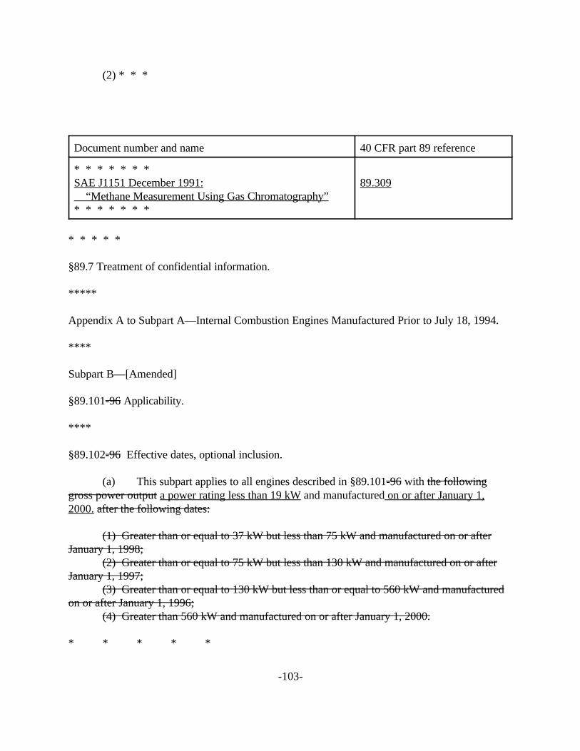
(2) * * *
Document number and name 40 CFR part 89 reference
* * * * * * * SAE J1151 December 1991:
“Methane Measurement Using Gas Chromatography” * * * * * * *
89.309
* * * * *
§89.7 Treatment of confidential information.
*****
Appendix A to Subpart A—Internal Combustion Engines Manufactured Prior to July 18, 1994.
****
Subpart B—[Amended]
§89.101-96 Applicability.
****
§89.102-96 Effective dates, optional inclusion.
(a) This subpart applies to all engines described in §89.101-96 with the following gross power output a power rating less than 19 kW and manufactured on or after January 1, 2000. after the following dates:
(1) Greater than or equal to 37 kW but less than 75 kW and manufactured on or after January 1, 1998;
(2) Greater than or equal to 75 kW but less than 130 kW and manufactured on or after January 1, 1997;
(3) Greater than or equal to 130 kW but less than or equal to 560 kW and manufactured on or after January 1, 1996;
(4) Greater than 560 kW and manufactured on or after January 1, 2000.
* * * * *
-103-

(c) Engines meeting the voluntary standards described in §89.112 (f) may be designated as Blue Sky Series engines through the 2004 model year.
(d) Implementation flexibility for equipment and vehicle manufacturers. Nonroad equipment and vehicle manufacturers and may take any of the otherwise prohibited actions identified in §89.1003(a)(1) with respect to the following nonroad equipment and vehicles, subject to the requirements of paragraph (e) of this section. The following allowances apply separately to each engine power category subject to standards under §89.112:
(1) Percent-of-production allowances. (A) Farm or logging. For farm equipment or vehicles, a manufacturer
may take any of the actions identified in §89.1003(a)(1) Alternative 1: for up to 30 percent of its U.S.-directed production volume of such equipment and vehicles in the first year that Tier 1 engine standards apply to such engines, and for up to 15 percent of its U.S.-directed production volume in each of the seven years following the first year; Alternative 2: for a portion of its U.S.-directed production volume of such equipment and vehicles during the eight years immediately following the date on which Tier 1 engine standards first apply to engines used in such equipment and vehicles, provided that the eight-year sum of these portions in each year, as expressed as a percentage for each year, does not exceed 135:
(B) Other equipment. For all other nonroad equipment and vehicles, a manufacturer may take any of the actions identified in §89.1003(a)(1) Alternative 1: for up to 15 percent of its U.S.-directed production volume of such equipment and vehicles in the first year that Tier 1 engine standards apply to such engines, and for up to 5 percent of its U.S.-directed production volume in each of the six years following the first year. Alternative 2: for a portion of its U.S.-directed production volume of such equipment and vehicles during the seven years immediately following the date on which Tier 1 engine standards first apply to engines used in such equipment and vehicles, provided that the seven-year sum of these portions in each year, as expressed as a percentage for each year, does not exceed 45.
(2) Small volume allowances. A nonroad equipment or vehicle manufacturer may exceed the production percentages in paragraph (d)(1) of this section in any of the years for which these percentages apply, provided that in each regulated power category, the manufacturer’s excepted equipment and vehicles in that year does not exceed 100 units, and is limited to a single equipment or vehicle model. POTENTIAL ALTERNATIVE
(d)(2) Small volume allowances. A nonroad equipment or vehicle manufacturer may exceed the production percentages in paragraph (d)(1) of this section, provided that in each regulated power category, the manufacturer’s total of excepted equipment and vehicles over the years in which the percent-of-production allowance applies does not exceed 100 units times the number of years in which the percent-of-production allowance applies, and is limited to a single equipment or vehicle model.
(3) Emission credit derived allowances. A nonroad equipment or vehicle manufacturer may exceed the allowances in paragraph (d)(1) of this section in any of the years for which these allowances apply, by retiring sufficient NMHC + NOx and PM emission credits obtained under the provisions of Subpart C of this Part. Equipment or vehicles for which these
-104-

emission credit-derived allowances are used must be excluded from the determinations required in paragraph (e) of this section.
(A) The amount of emission credits, in megagrams, to be retired for each additional allowance must be determined separately for NMHC + NOx and for PM as follows: Emission credits = [(Previous level) - (New level)] x (Category PR) x (UL) x (10-6) Where:
Previous level = 16.0 g/kW-hr NMHC + NOx and 1.2 g/kW-hr for PM. New level = The emission standard that would apply to the engine used in the equipment if no allowance were to be used. Category PR = The midpoint of the power range in §89.112 applying to the engine used in the equipment for which the allowance is being used. UL = The useful life for the engine family, in hours.
(B) A nonroad equipment or vehicle manufacturer choosing to retire emission credits must submit an end-of-the-year report in accordance with the requirements of §89.211 in each year that credits are retired.
(4) Inclusion of previous-tier engines. Equipment and vehicles built with previous tier or noncertified engines under the existing inventory provisions of §89.1003(b)(4) need not be included in determining compliance with paragraphs (d)(1), (d)(2), and (d)(3) of this section, at the manufacturer’s option.
(e) Determination of compliance and recordkeeping. The following applies to nonroad equipment or vehicle manufacturers who produce excepted equipment or vehicles under the provisions of paragraph (d) of this section:
(1) After each year in which excepted equipment or vehicles are produced, a determination of compliance with the requirements of paragraph (d) of this section must be made. This determination shall be based on actual production information from the subject year and must be made within 3 months after the availability of such information. Should any such determination reveal that a production percentage allowance (or small volume allowance where applied) for a power category has been exceeded for the subject year, the nonroad equipment or vehicle manufacturer must adjust that category’s percentage allowance and small volume allowance for the year after the subject year (from zero in the year after the final year of the allowance). The percentage allowance must be recalculated by subtracting the excess percentage of excepted machines from the percentage allowance that would otherwise apply in the year after the subject year. The small volume allowance must be recalculated by subtracting the excess number of excepted machines in the subject year from 100 (from zero in the year after the final year of the allowance). If both the recalculated percentage allowance and the recalculated small volume allowance for the year after the subject year is less than zero in any power category, then the manufacturer is in violation of section 203 of the Act and §89.1003 of these regulations. POTENTIAL ALTERNATIVE
(e)(1) For each power category in which excepted equipment or vehicles are produced, a determination of compliance with the requirements of paragraph (d) of this section must be made. This determination must be made no later than December 31 of the year following
-105-

the last year in which allowances apply, and must be based on actual production information from the subject years. Should any such determination reveal that both the percentage allowance and the small volume allowance have been exceeded, then the manufacturer is in violation of section 203 of the Act and §89.1003.
(2) A nonroad equipment or vehicle manufacturer must keep records of all equipment and vehicles excepted under the provisions of paragraph (d) of this section, for each power category in which exceptions are taken. These records must include equipment and engine model numbers, serial numbers, and dates of manufacture, and engine rated power. In addition, the manufacturer must keep records sufficient to demonstrate the annual determination of compliance required in paragraph (e)(1) of this section. All such records must be kept until at least two full years after the final year in which exceptions are available for each power category.
(f) Hardship relief. Nonroad equipment and vehicle manufacturers, and post-manufacture marinizers, that qualify as small entities under 13 CFR Part 121 may take any of the otherwise prohibited actions identified in §89.1003(a)(1) beyond those allowed under paragraph (d) of this section, subject to approval by the Administrator and the following requirements:
(1) Application for relief must be submitted to the Mobile Source Operations Division in writing prior to the earliest date in which the applying manufacturer would be in violation of §89.1003.
(2) Evidence must be provided that the conditions causing the impending violation are not substantially the fault of the applying manufacturer.
(3) Evidence must be provided that the applying manufacturer may be forced to permanently close or sell its equipment-producing operation if relief is not granted.
(4) Any relief granted must begin within one year after the implementation date of the standard applying to engines being used in the equipment for which relief is requested, and may not exceed one year in duration.
(g) Allowance for the production of engines. Engine manufacturers may take any of the otherwise prohibited actions identified in §89.1003(a)(1) with regard to uncertified engines or Tier 1 engines, as appropriate, if the engine manufacturer has received written assurance that the engine is required to meet the demand for engines created under paragraph (d) and (f) of this section.
§89.103-96 Definitions.
*****
§89.104-96 Useful life, recall, and warranty periods.
(a) The useful life is a period of 8000 3,000 hours of operation or ten five years of use, whichever first occurs.
-106-

(b) Engines are subject to recall testing for a period of 6,000 2,250 hours of operation or seven four years of use, whichever first occurs.
(c) Warranties imposed by the Clean Air Act are for 3,000 1,500 hours of operation or five three years of use, whichever first occurs. *****
§89.105-96 Certificate of conformity.
*****
§89.106-96 Prohibited controls.
*****
§89.107-96 Defeat devices.
*****
§89.108-96 Adjustable parameters, requirements.
§89.109-96 Maintenance instructions and minimum allowable maintenance intervals.
(a)
III I*****
The manufacturer must furnish or cause to be furnished to the ultimate purchaser of each new nonroad engine written instructions for the maintenance needed to ensure proper functioning of the emission control system.
(b) Maintenance performed on equipment, engines, subsystems or components used to determine exhaust emission deterioration factors is classified as either emission-related or nonemission-related and each of these can be classified as either scheduled or unscheduled. Further, some emission-related maintenance is also classified as critical emission-related maintenance.
(c) This paragraph specifies emission-related scheduled maintenance for purposes of obtaining durability data and for inclusion in maintenance instructions furnished to purchasers of new nonroad engines. The maintenance intervals specified below are minimum intervals.
(1) All emission-related scheduled maintenance for purposes of obtaining durability data must occur at the same hours of use intervals that will be specified in the manufacturer’s maintenance instructions furnished to the ultimate purchaser of the engine under paragraph (a) of this section. This maintenance schedule may be updated as necessary throughout the testing of the engine, provided that no maintenance operation is deleted from the maintenance schedule after the operation has been performed on the test vehicle or engine.
-107-

(2) Any emission-related maintenance that is performed on vehicles, engines, subsystems, or components must be technologically necessary to assure in-use compliance with the emission standards. The manufacturer must submit data that demonstrate to the Administrator that all of the emission-related scheduled maintenance that is to be performed is technologically necessary. Scheduled maintenance must be approved by the Administrator prior to being performed or being included in the maintenance instructions provided to the purchasers under paragraph (a) of this section. The Administrator has determined that emission-related maintenance in addition to or at shorter intervals than those outlined in paragraphs (c)(3) and (c)(4) of this section is not technologically necessary to ensure in-use compliance and therefore will not be accepted. However, the Administrator may determine that maintenance even more restrictive (e.g., longer intervals) than that listed in paragraphs (c)(3) and (c)(4) of this section is also not technologically necessary.
(3) For nonroad compression-ignition engines, the adjustment, cleaning, repair, or replacement listed in paragraphs (c)(3)(i) through (c)(3)(iii) of this section must occur at 1,500 hours of use and at 1,500-hour intervals thereafter.
(i) Exhaust gas recirculation system-related filters and coolers. (ii) Positive crankcase ventilation valve. (iii) Fuel injector tips (cleaning only).
(4) The adjustment, cleaning and repair in paragraphs(c)(4)(i) through (c)(4)(vii) of this section must occur at 3,000 hours of use and at 3,000-hour intervals thereafter.
(i) Fuel injectors. (ii) Turbocharger. (iii) Electronic engine control unit and its associated sensors and
actuators. (iv) Particulate trap or trap-oxidizer system (including related
components). (v) Exhaust gas recirculation system (including all related control
valves and tubing) except as otherwise provided in paragraph (c)(3)(i) of this section. (vi) Catalytic convertor. (vii) Any other add-on emission-related component (i.e., a component
whose sole or primary purpose is to reduce emissions or whose failure will significantly degrade emission control and whose function is not integral to the design and performance of the engine).
(5) (i) The components listed in paragraphs(c)(5)(i)(A) through-(c)(5)(i)(F) of this section are currently defined as critical emission-related components.
(A) Catalytic convertor (B) Electronic engine control unit and its associated sensors and
actuators. (C) Exhaust gas recirculation system (including all related
filters, coolers, control valves, and tubing). (D) Positive crankcase ventilation valve. (E) Particulate trap or trap-oxidizer system.
-108-

(F) Any other add-on emission-related component (i.e., a component whose sole or primary purpose is to reduce emissions or whose failure will significantly degrade emission control and whose function is not integral to the design and performance of the engine).
(ii) All critical emission-related scheduled maintenance must have a reasonable likelihood of being performed in-use. The manufacturer will be required to show the reasonable likelihood of such maintenance being performed in-use. Critical emission-related scheduled maintenance items that satisfy one of the conditions defined in paragraphs (c)(5)(ii)(A) through (c)(5)(ii)(F) of this section will be accepted as having a reasonable likelihood of the maintenance item being performed in-use.
(A) Data are presented that establish for the Administrator a connection between emissions and vehicle performance such that as emissions increase due to lack of maintenance, vehicle performance will simultaneously deteriorate to a point unacceptable for typical driving.
(B) Survey data are submitted which adequately demonstrate to the Administrator that, at an 80 percent confidence level, 80 percent of such engines already have this critical maintenance item performed in-use at the recommended interval(s).
(C) A clearly displayed visible signal system approved by the Administrator is installed to alert the equipment operator that maintenance is due. A signal bearing the message “maintenance needed” or “check engine,” or a similar message approved by the Administrator, will be actuated at the appropriate usage point or by component failure. This signal must be continuous while the engine is in operation and not be easily eliminated without performance of the required maintenance. Resetting the signal will be a required step in the maintenance operation. The method for resetting the signal system will be approved by the Administrator. The system must not be designed to deactivate upon the end of the useful life of the engine or thereafter.
(D) A manufacturer may desire to demonstrate through a survey that a critical maintenance item is likely to be performed without a visible signal on a maintenance item for which there is no prior in-use experience without the signal. To that end, the manufacturer may in a given model year market up to 200 randomly selected vehicles per critical emission-related maintenance item without such visible signals, and monitor the performance of the critical maintenance item by the owners to show compliance with paragraph (c)(5)(ii)(B) of this section. This option is restricted to two consecutive model years and may not be repeated until any previous survey has been completed. If the critical maintenance involves more than one engine family, the sample will be sales weighted to ensure that it is representative of all the families in question.
(E) The manufacturer provides the maintenance free of charge, and clearly informs the customer that the maintenance is free in the instructions provided under paragraph (a) of this section.
(F) Any other method that the Administrator approves as establishing a reasonable likelihood that the critical maintenance will be performed in-use.
-109-

(iii) Visible signal systems used under paragraph (c)(5)(ii)(C) of this section are considered an element of design of the emission control system. Therefore, disabling, resetting, or otherwise rendering such signals inoperative without also performing the indicated maintenance procedure is a prohibited act.
(d) Nonemission-related scheduled maintenance that is reasonable and technologically necessary (e.g., oil change, oil filter change, fuel filter change, air filter change, cooling system maintenance, adjustment of idle speed, governor, engine bolt torque, valve lash, injector lash, timing, lubrication of the exhaust manifold heat control valve, etc.) may be performed on durability vehicles at the least frequent intervals recommended by the manufacturer to the ultimate purchaser, (e.g., not the intervals recommended for severe service).
(e) Adjustment of engine idle speed on emission data engines may be performed once before the low-hour emission test point. Any other engine, emission control system, or fuel system adjustment, repair, removal, disassembly, cleaning, or replacement on emission data vehicles must be performed only with advance approval of the Administrator.
(f) Equipment, instruments, or tools may not be used to identify malfunctioning, maladjusted, or defective engine components unless the same or equivalent equipment, instruments, or tools will be available to dealerships and other service outlets and:
(1) Are used in conjunction with scheduled maintenance on such components; or
(2) Are used subsequent to the identification of a vehicle or engine malfunction, as provided in paragraph (e) of this section for emission data engines; or
(3) Unless specifically authorized by the Administrator.
(g) All test data, maintenance reports, and required engineering reports must be compiled and provided to the Administrator in accordance with §89.124.
*****
§89.110-96 Emission control information label.
*****
(b) *** (9) Family emission limits (FELs) if applicable; and (10) The statement: “This engine conforms to [model year] U.S. EPA
regulations large nonroad compression ignition engines.;” (11) Engines belonging to an engine family that has been certified as a constant-
speed engine using the test cycle specified in Table 2 of appendix B to subpart E of this part must contain the statement on the label: “constant-speed only”.
-110-

(12) (i) Engines meeting the voluntary standards described in §89.112 (f)(1)-
to be designated as Blue Sky Series engines must contain the statement on the label: “Blue Sky—Class A”.
(ii) Engines meeting the voluntary standards described in §89.112 (f)(2) to be designated as Blue Sky Series engines must contain the statement on the label: “Blue Sky—Class AA”.
(iii) Engines meeting the voluntary standards described in §89.112 (f)(3) to be designated as Blue Sky Series engines must contain the statement on the label: “Blue Sky—Class AAA”. *****
§89.111-96 Averaging, banking, and trading of exhaust emissions.
*****
§89.112-96 Oxides of nitrogen, carbon monoxide, hydrocarbon, and particulate matter exhaust emission standards.
(a) Nonroad engines to which this subpart is applicable must meet the following exhaust emission standards contained in Table 1. :
(1) Exhaust emissions of oxides of nitrogen shall not exceed 9.2 grams per kilowatt hour (g/kW-hr).
(2) Exhaust emissions of carbon monoxide shall not exceed 11.4 g/kW-hr for engines at and above 130 kW.
(3) Exhaust emissions of hydrocarbon shall not exceed 1.3 g/kW-hr for engines at and above 130 kW.
(4) Exhaust emissions of particulate matter shall not exceed 0.54 g/kW-hr for engines at and above 130 kW.
Table 1. - Emission Standards (g/kW-hr)
Rated Brake Power (kW)
Model Year NOx HC
NMHC+ NOx CO PM
kW<8 2000 — — 10.5 8.0 1.0
2005 — — 7.5 8.0 0.80
8#kW<19 2000 — — 9.5 6.6 0.80
2005 — — 7.5 6.6 0.80
-111-

(b) Exhaust emissions of oxides of nitrogen, carbon monoxide, and hydrocarbon, and nonmethane hydrocarbon are measured using the procedures set forth in subpart E of this part.
*****
(d) In lieu of the NOx standards, NMHC + NOx standards, and PM standards specified in paragraph (a) (1) of this section, manufacturers may elect to include engine families in the averaging, banking, and trading program, the provisions of which are specified in subpart C of this part. The manufacturer must set a family emission limit (FEL) not to exceed 14.6 grams per kilowatt hour the levels contained in Table 2. The This FEL established by the manufacturer serves as the standard for that engine family.
Table 2. - Upper Limit for Family Emission Limits (g/kW-hr)
Rated Brake Model NOx NMHC+ NOx PM Power (kW) Year FEL FEL FEL
kW<8 2000 — 16.0 1.2
2005 — 10.5 1.0
8#kW<19 2000 — 16.0 1.2
2005 — 9.5 0.80
(e) Naturally aspirated nonroad engines to which this subpart is applicable must not discharge crankcase emissions into the ambient atmosphere. This provision applies to all 2001 model year engines and later models. This provision does not apply to engines using turbochargers, pumps, blowers, or superchargers for air induction.
(f) Engines may be designated “Blue Sky Series” engines through the 2004 model year by meeting the following voluntary standards, that apply to all certification and in-use testing. Emissions are measured using the procedures set forth in part 86, subpart N. Manufacturers may use an alternate procedure to demonstrate the desired level of emission control if approved in advance by the Administrator. Engines meeting the requirements to qualify as Blue Sky Series engines must be capable of maintaining a comparable level of emission control when tested using the procedures set forth in paragraph (c) of this section and subpart E of this part. The numerical emission levels measured using the procedures from this part may be up to 20 percent higher than those measured using the procedures from part 86, subpart N and still be considered comparable. Engines designated as Blue Sky Series engines must meet the requirements related to in-use durability detailed in §§89.104, 89.109, 89.118, and 89.130; alternatively, manufacturers may fulfill these requirements with the comparable provisions from part 86.
(1) Engines certified to voluntary standards at least 35 percent below the numerical level established for Tier 2 engines, for both particulate matter and NMHC + NOx, may be designated as a “Blue Sky Series engine—Class A”. Manufacturers must also demonstrate
-112-
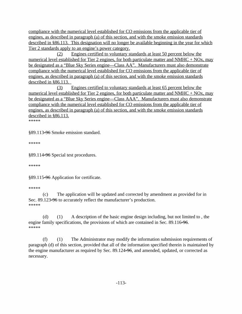
compliance with the numerical level established for CO emissions from the applicable tier of engines, as described in paragraph (a) of this section, and with the smoke emission standards described in §86.113. This designation will no longer be available beginning in the year for which Tier 2 standards apply to an engine’s power category.
(2) Engines certified to voluntary standards at least 50 percent below the numerical level established for Tier 2 engines, for both particulate matter and NMHC + NOx, may be designated as a “Blue Sky Series engine—Class AA”. Manufacturers must also demonstrate compliance with the numerical level established for CO emissions from the applicable tier of engines, as described in paragraph (a) of this section, and with the smoke emission standards described in §86.113.
(3) Engines certified to voluntary standards at least 65 percent below the numerical level established for Tier 2 engines, for both particulate matter and NMHC + NOx, may be designated as a “Blue Sky Series engine—Class AAA”. Manufacturers must also demonstrate compliance with the numerical level established for CO emissions from the applicable tier of engines, as described in paragraph (a) of this section, and with the smoke emission standards described in §86.113. *****
§89.113-96 Smoke emission standard.
*****
§89.114-96 Special test procedures.
*****
§89.115-96 Application for certificate.
***** (c) The application will be updated and corrected by amendment as provided for in
Sec. 89.123-96 to accurately reflect the manufacturer’s production.-*****
(d) (1) A description of the basic engine design including, but not limited to , the engine family specifications, the provisions of which are contained in Sec. 89.116-96.-*****
(f) (1) The Administrator may modify the information submission requirements of paragraph (d) of this section, provided that all of the information specified therein is maintained by the engine manufacturer as required by Sec. 89.124-96, and amended, updated, or corrected as necessary.
-113-

(2) For the purposes of this paragraph, Sec. 89.124-96(a)(1) includes all information specified in paragraph (d) of this section whether or not such information is actually submitted to the Administrator for any particular model year.
§89.116-96 Engine families.
*****
§89.117-96 Test fleet selection.
(a) The manufacturer must select for testing, from each engine family, the engine with the most fuel injected per stroke of an injector at maximum power, primarily at the speed of maximum torque and secondarily at rated speed.
*****
(d) For establishing deterioration factors, the manufacturer must select the engines, subsystems, or components to be used to determine exhaust emission deterioration factors for each engine-family control system combination. Whether engines, subsystems, or components are used, they must be selected so that their emission deterioration characteristics may be expected to represent those of in-use engines, based on good engineering judgment.
§89.118-96 Service accumulation.
***** (e) This paragraph describes service accumulation requirements for the purpose of
deterioration factor development. Paragraphs (b) through (d) of this section also apply here. (1) Service accumulation on engines, subsystems, or components selected by
the manufacturer under §89.117 (d). The manufacturer determines the form and extent of this service accumulation, consistent with good engineering practice, and describes it in the application for certification.
(2) Determination of exhaust emission deterioration factors. The manufacturer determines the form and extent of the service accumulation, consistent with good engineering practice, and describes it in the application for certification.
(3) Alternatives to service accumulation and testing for the determination of a deterioration factor. A written explanation of the appropriateness of using an alternative must be included in the application for certification.
-114-

(i) Carryover and carryacross of durability emission data. In lieu of -
testing an emission data or durability data engine selected under §89.117 (d), and submitting data therefore, a manufacturer may, with the approval of the Administrator, submit exhaust emission deterioration data on a similar engine for which certification to the same standard has previously been obtained or for which all applicable data required under §89.124 has previously been submitted.
(ii) Use of on-highway deterioration data. In the case where a manufacturer produces a certified on-highway engine that is similar to the nonroad engine to be certified, deterioration data from the on-highway engine may be applied to the nonroad engine. This application of deterioration data from an on-highway engine to a nonroad engine is subject to Administrator approval, and the determination of whether the engines are similar must be based on good engineering judgment.
(iii) Engineering analysis for established technologies. In the case where an engine family uses technology that is well established, an analysis based on good engineering practices may be used in lieu of testing to determine a deterioration factor for that engine family. The engineering analysis and the determination of whether or not an engine is using established technologies are both subject to Administrator approval.
§89.119-96 Emission tests.
***** (a) (1) Upon completion of service accumulation, the manufacturer must test each
test engine using the specified test procedures, except as provided in Sec. 89.114-96. The procedures to be used are set forth in:
*****
(d) Test fuels. EPA may use the fuel specified in either Table 4 or Table 5 of appendix A to subpart D of this part in confirmatory testing or other testing on any engine. Emission test results based on use of Table 5 fuel will be used to confirm compliance with HC, CO, NOx, PM, and smoke standards. Emission test results based on Table 4 fuel will be used to confirm compliance with HC, CO, NOx, and smoke standards; when a manufacturer uses the fuel specified in Table 4 of appendix A to subpart D of this part for its certification testing, EPA has the option to use the PM emission result, corrected using the PM correction factor specified in Sec. 89.425-96, to confirm compliance with the PM standard.
§89.120-96 Compliance with emission standards.
***** (c) If aftertreatment is employed by an For each nonroad compression-ignition engine
family, then a deterioration factor must be determined and applied.
-115-

(1) The applicable exhaust emission standards (or family emission limits, as appropriate) for nonroad compression-ignition engines apply to the emissions of engines for their useful life.
(2) Since emission control efficiency generally decreases with the accumulation of service on the engine, deterioration factors will be used in combination with emission data engine test results as the basis for determining compliance with the standards.
(3) (i) Paragraph (c)(3) of this section describes the procedure for determining compliance of an engine with emission standards (or family emission limits, as appropriate), based on deterioration factors supplied by the manufacturer. Deterioration factorsbe established using applicable emission test procedures. NMHC + NOx deterioration factors must be established based on the sum of the pollutants. When establishing deterioration factors for NMHC + NOx, a negative deterioration (emissions decrease from the official emissions test result) for one pollutant may not offset deterioration of the other pollutant. Where negative deterioration occurs for NOx or NMHC, the official exhaust emission test result must be used for purposes of determining the NMHC + NOx deterioration factor.
(ii) Separate exhaust emission deterioration factors, determined from tests of engines, subsystems, or components conducted by the manufacturer, must be supplied for each engine-system combination. Separate factors must be established for NMHC, CO, NOx, NMHC + NOx, and exhaust particulate. For smoke testing, separate factors must also be established for the acceleration mode (designated as “A”), the lugging mode (designated as “B”), and peak opacity (designated as “C”).
(iii) Compression-ignition nonroad engines not utilizing aftertreatment technology (e.g., particulate traps). For NMHC, CO, NOx, NMHC + NOx, and exhaust particulate, the official exhaust emission results for each emission data engine at the selected test point must be adjusted by addition of the appropriate deterioration factor. However, if the deterioration factor supplied by the manufacturer is less than zero, it must be zero for the purposes of this paragraph.
(iv) Compression-ignition nonroad engines utilizing aftertreatment technology (e.g., particulate traps). For NMHC, CO, NOx, NMHC + NOx, and exhaust particulate, the official exhaust emission results for each emission data engine at the selected test point must be adjusted by multiplication by the appropriate deterioration factor. However, if the deterioration factor supplied by the manufacturer is less than one, it must be one for the purposes of this paragraph.
(v) For acceleration smoke (“A”), lugging smoke (“B”), and peak opacity (“C”), the official exhaust emission results for each emission data engine at the selected test point must be adjusted by the addition of the appropriate deterioration factor. However if the deterioration supplied by the manufacturer is less than zero, it must be zero for the purposes of this paragraph.
(vi) The emission values to compare with the standards (or family emission limits, as appropriate) must be the adjusted emission values of paragraphs (c)(3)(iii) through (v) of this section, rounded to the same number of significant figures as contained in the applicable standard in accordance with ASTM E29-93a, for each emission data engine. This procedure has been incorporated by reference (see §89.6).
-116-

(4) Every test engine of an engine family must comply with all applicable standards (or family emission limits, as appropriate), as determined in paragraph (c)(3)(vi) of this section, before any engine in that family will be certified. *****
(e) For the purposes of setting an NMHC + NOx certification level or FEL, one of the following options must be used for the determination of NMHC for an engine family. The manufacturer must declare that option is used in its application for certification of that engine family.
(1) THC may be used in lieu of NMHC for the standards set forth in §89.112. (2) The manufacturer may choose its own method to analyze methane with
prior approval of the Administrator. (3) The manufacturer may assume that two percent of the measured THC is
methane (NMHC = 0.98 × THC).
§89.121-96 Certificate of conformity effective dates.
*****
§89.122-96 Certification.-
*****
§89.123-96 Amending the application and certificate of conformity.-*****
§89.124-96 Record retention, maintenance, and submission.
*****
§89.125-96 Production engines, annual report.
*****
§89.126-96 Denial, revocation of certificate of conformity.-
*****
(b) (5) The manufacturer denies an EPA enforcement officer of EPA authorized representative reasonable assistance (as defined in Sec. 89.129-96(e)).
-117-

(c) If a manufacturer knowingly commits an infraction specified in paragraph (b)(1) or (b)(4) of this section, knowingly commits any other fraudulent act which that results in the issuance of a certificate of conformity, or fails to comply with the conditions specified in Secs. 89.203-96 (f) (d), 89.206-96 (d) (c), 89.209-96(c) or 89.210-96(g), the Administrator may deem such certificate void ab initio.
(d) When the Administrator denies, suspends, revokes, or voids ab initio a certificate of conformity the manufacturer will be provided a written determination. The manufacturer may request a hearing under Sec. 89.127-96 on the Administrator’s decision.-
*****
§89.127-96 Request for hearing.-
*****
§89.128-96 Hearing procedures.-
*****
(b) (1) (i) The determination issued by the Administrator under Sec. 89.126-96(d);-
*****
§89.129-96 Right of entry.
*****
§89.130 Rebuild practices.
(a) The provisions of this section are applicable to engines subject to the standards prescribed in section §89.112 and are applicable to the process of engine rebuilding (or rebuilding a portion of an engine or engine system). The process of engine rebuilding generally includes disassembly, replacement of multiple parts due to wear, and reassembly, and also may include the removal of the engine from the vehicle and other acts associated with rebuilding an engine. Any deviation from the provisions contained in this section is a prohibited act.
(b) When rebuilding an engine, portions of an engine, or an engine system, there must be a reasonable technical basis for knowing that the resultant engine is equivalent, from an emissions standpoint, to a certified configuration (i.e., tolerances, calibrations, specifications) of the same or newer model year as the original engine. A reasonable basis would exist if:
-118-

(1) Parts installed, whether the parts are new, used, or rebuilt, are such that a person familiar with the design and function of motor vehicle engines would reasonably believe that the parts perform the same function with respect to emission control as the original parts, and
(2) Any parameter adjustment or design element change is made only: (i) in accordance with the original engine manufacturer's instructions;
or (ii) where data or other reasonable technical basis exists that such
parameter adjustment or design element change, when performed on the engine or similar engines, is not expected to adversely affect in-use emissions.
(c) When an engine is being rebuilt and remains installed or is reinstalled in the same equipment, it must be rebuilt to a configuration of the same or later model year as the original engine. When an engine is being replaced, the replacement engine must be an engine of (or rebuilt to) a configuration of the same or later model year as the original engine.
(d) At time of rebuild, emission-related codes or signals from on-board monitoring systems may not be erased or reset without diagnosing and responding appropriately to the diagnostic codes, regardless of whether the systems are installed to satisfy requirements in §89.109 or for other reasons and regardless of form or interface. Diagnostic systems must be free of all such codes when the rebuilt engine is returned to service. Such signals may not be rendered inoperative during the rebuilding process.
(e) When conducting a rebuild without removing the engine from the equipment, or during the installation of a rebuilt engine, all critical emission-related components listed in §86.109-99(d) not otherwise addressed by paragraphs (b) through (d) of this section must be checked and cleaned, adjusted, repaired, or replaced as necessary, following manufacturer recommended practices.
(f) Records must be kept by parties conducting activities included in paragraphs (b) through (e) of this section. The records must include at minimum the hours of operation at time of rebuild, a listing of work performed on the engine, and emission-related control components including a listing of parts and components used, engine parameter adjustments, emission-related codes or signals responded to and reset, and work performed under paragraph (e) of this section.
(1) Parties may keep records in whatever format or system they choose as long as the records are understandable to an ARB enforcement officer or can be otherwise provided to an ARB enforcement officer in an understandable format when requested.
(2) Parties are not required to keep records of information that is not reasonably available through normal business practices including information on activities not conducted by themselves or information that they cannot reasonably access.
(3) Parties may keep records of their rebuilding practices for an engine family rather than on each individual engine rebuilt in cases where those rebuild practices are followed routinely.
-119-

(4) Records must be kept for a minimum of two years after the engine is rebuilt.
Subpart C—Averaging, Banking, and Trading Provisions
§89.201-96 Applicability.
*****
§89.202-96 Definitions.
*****
§89.203-96 General provisions.-
(a) The averaging, banking, and trading programs for NOx, NMHC + NOx, and PM emissions from eligible nonroad engines are described in this subpart. Participation in this these programs is voluntary.
- -
(b) DELETE
(c) DELETE,
REPLACE WITH:
(c) (1) A nonroad engine family is eligible to participate in the averaging, banking, and trading program for NMHC + NOx emissions and PM emissions if it is subject to regulation under subpart B of this part with certain exceptions specified in subsection (c)(2) of this section. No averaging, banking, and trading program is available for meeting the CO or smoke emission standards specified in subpart B of this part.
(2) Nonroad engines may not participate in the averaging, banking, and trading program if they are subject to state engine emission standards, are exported, or use an alternate or special test procedure under §89.114. Meeting the voluntary standards described in §89.112 (f) for Blue Sky Series engines does not preclude participation in the averaging, banking, and trading program; however, participation in the averaging, banking, and trading program depends on manufacturers developing test data on a steady-state test cycle, as specified in §89.410 (a), for credit computation purposes.
(3) (i) A manufacturer may certify one or more nonroad engine families at-FELs above or below the applicable NMHC + NOx emission standard and PM emission standard, provided the summation of the manufacturer's projected balance of all NMHC + NOx credit transactions and the summation of the manufacturer’s projected balance of all PM credit transactions in a given model year in a given averaging set is greater than or equal to zero, as determined under §89.207 (b).
-120-
(A) FELs for NMHC + NOx and FELs for PM may not exceed the upper limits specified in §89.112 (d).
(B) An engine family certified to an FEL is subject to all provisions specified in subparts B, D, E, F, G, H, I, J, and K of this part, except that the applicable FEL replaces the emission standard for the family participating in the averaging, banking, and trading program.
(C) A manufacturer of an engine family with an FEL exceeding the applicable emission standard must obtain emission credits sufficient to address the associated credit shortfall via averaging, banking, or trading, within the restrictions described in §89.204 (c) and §89.206 (b)(4).
(D) An engine family with an FEL below the applicable standard may generate emission credits for averaging, banking, trading, or a combination thereof. Emission credits may not be used to offset an engine family's emissions that exceed its applicable FEL. Credits may not be used to remedy nonconformity determined by a Selective Enforcement Audit (SEA) or by recall (in-use) testing. However, in the case of an SEA failure, credits may be used to allow subsequent production of engines for the family in question if the manufacturer elects to recertify to a higher FEL.
(ii) (A) In lieu of generating credits under paragraph (c)(3)(i) of this section, a manufacturer may certify one or more nonroad engine families at family emission limits (FELs) above or below the applicable NMHC + NOx emission standard and PM emission standard. The summation of the manufacturer's projected balance of all NMHC + NOx credit transactions and the summation of the manufacturer’s projected balance of all PM credit transactions in a given model year, as determined under §89.207 (b), is allowed to be less than zero.
(B) A penalty equal to ten percent of the year end negative credit balance must be added to the negative credit balance. The resulting negative credit balance must be carried into the next model year.
(C) A manufacturer will be allowed to carry over a negative credit balance until December 31, 2003. As of this date, the summation of the manufacturer's projected balance of all NMHC + NOx credit transactions and the summation of the manufacturer’s projected balance of all PM credit transactions must be greater than or equal to zero.
(D) FELs for NMHC + NOx and FELs for PM may not exceed the upper limits specified in §89.112 (d).
(E) An engine family certified to an FEL is subject to all provisions specified in subparts B, D, E, F, G, H, I, J, and K of this part, except that the applicable NMHC + NOx FEL or PM FEL replaces the NMHC + NOx emission standard or PM emission standard for the family participating in the averaging and banking program.
(F) A manufacturer of an engine family with an FEL exceeding the applicable emission standard must obtain emission credits sufficient to address the associated credit shortfall via averaging or banking. The exchange of emission credits generated under this program with other nonroad engine manufacturers in trading is not allowed.
-121-

(G) An engine family with an FEL below the applicable standard may generate emission credits for averaging, banking, or a combination thereof. Emission credits may not be used to offset an engine family's emissions that exceed its applicable FEL. Credits may not be used to remedy nonconformity determined by a Selective Enforcement Audit (SEA) or by recall (in-use) testing. However, in the case of an SEA failure, credits may be used to allow subsequent production of engines for the family in question if the manufacturer elects to recertify to a higher FEL.
(4) (i) Except as noted in paragraphs (c)(4)(ii), (c)(4)(iii), and (c)(4)(iv) of this section, credits generated in a given model year may be used in any following model year. Except as allowed under paragraph (c)(3)(ii) of this section, credits generated in one model year may not be used for prior model years.
(ii) Credits generated prior to the implementation date of the applicable Tier 2 standards, will expire on December 31, 2007.
(iii) Credits generated under the provisions of paragraph (c)(3)(ii) will expire on December 31, 2003.
(d) DELETE,
REPLACE WITH:
(d) Manufacturers must demonstrate compliance under the averaging, banking, and trading program for a particular model year by 270 days after the model year. Engine families without an adequate amount of emission credits, except as allowed under paragraph (c)(3)(ii) of this section, will violate the conditions of the certificates of conformity. The certificates of conformity may be voided ab initio under §89.126-96 (c) for those engine families.
(e) DELETE,
REPLACE WITH:
Engine families may not generate credits for one pollutant while also using credits for another pollutant in the same model year.
(f) DELETE,
REPLACE WITH:
An engine manufacturer may make exchange NMHC + NOx emission credits and PM credits to equipment or vehicle manufacturers in trading. Such credits may be used within the provisions specified in §89.102 (d)(3).
-122-

§89.204-96 Averaging.
(a) DELETE
(b) DELETE,
REPLACE WITH:
(b) (1) A manufacturer may use averaging to offset an emission exceedance of a-nonroad engine family caused by an NMHC + NOx FEL or a PM FEL above the applicable
emission standard. Credits used in averaging may be obtained from credits generated by another engine family in the same model year, credits banked in previous model years that have not expired, or credits obtained through trading. The use of credits must be within the restrictions described in paragraph (c) of this section and §89.206 (b)(4).
(2) Credits scheduled to expire in the earliest model year must be used first, before using other available credits.
§89.205-96 Banking.
(a) A manufacturer of a nonroad engine family with an NMHC + NOx FEL or a PM FEL below the applicable standard for a given model year may bank credits in that model year for use in averaging and trading in the following three model years any following model year. Credits not withdrawn within the three model years after they are banked are forfeited.
(b) A manufacturer of a nonroad engine family may bank credits up to one calendar year prior to the effective date of mandatory certification. Such engines must meet the requirements of subparts A, B, D, E, F, G, H, I, J, and K of this part.
(c) A manufacturer may bank actual credits only after the end of the model year and after EPA has reviewed the manufacturer's end-of-year reports. During the model year and before submittal of the end-of-year report, credits originally designated in the certification process for banking will be considered reserved and may be redesignated for trading or averaging in the end-of-year report and final report.
(d) Credits declared for banking from the previous model year that have not been reviewed by EPA ARB may be used in averaging or trading transactions. However, such credits may be revoked at a later time following EPA ARB review of the end-of-year report or any subsequent audit actions.
-123-

§89.206-96 Trading.
*****
(b) Credits for trading can be obtained from credits banked in the three previous model years that have not expired or credits generated during the model year of the trading transaction. Traded credits expire if they are not used in averaging within three model years following the model year in which they were generated.
(c) Traded credits can be used for averaging, banking, or further trading transactions within the restrictions described in §89.204 (b) and paragraph (b) of this section.
(d) In the event of a negative credit balance resulting from a transaction, both the buyer and seller are liable, except in cases involving fraud. Certificates of all engine families participating in a negative trad may be voided ab initio under §89.126-96(c).
§89.207-96 Credit calculation.
For each participating engine family, NOx + NMHC emission credits and PM emission credits (positive or negative) are to be calculated according to one of the following equations and rounded, in accordance with ASTM E29-903a- _ , to the nearest one-tenth of a megagram per hour (Mg/hr). ASTM E29-903a has been incorporated by reference. (see §89.6). Consistent units are to be used throughout the equation.
(a) For determining credit availability from all engine families generating credits:
Emission credits = (Std - FEL) x (Volume) x (MinPR) (AvgPR) x (UL) x (10-6)
(b) For determining credit usage for all engine families requiring credits to offset emissions in excess of the standard:
Emission credits = (Std - FEL) x (Volume) x (Max) (AvgPR) x (UL) x (10-6)
Where: Std = the current and applicable nonroad Tier 2 engine emission standard, in grams per brake
horsepower hour. (Engines participating in the averaging and banking program provisions of §89.203 (c)(3)(ii) must use the Tier 1 standard for credit calculations.)
FEL = the family emission limit for the engine family in grams per brake horsepower hour. Volume = the number of nonroad engines eligible to participate in the averaging, banking, and
trading program within the given engine family during the model year. Engines sold to equipment or vehicle manufacturers under the provisions of §89.102(g) must not be included in this number. Quarterly production projections are used for initial certification.
-124-

Actual applicable production/sales volumes is used for end-of-year compliance determination.
MinPR=the power rating of the configuration within an engine family with the lowest power rating.
MaxPR= the power rating of the configuration within an engine family with the highest power rating.
AvgPR = the average power rating of all of the configurations within an engine family, calculated on a sales-weighted basis.
UL = the useful life for the given engine family, in hours.
§89.208-96 Labeling.
For all nonroad engines included in the averaging, banking, and trading program, the family emission limits to which the engine is certified must be included on the label required in §89.110-96.
§89.209-96 Certification.
(a) In the application for certification a manufacturer must: (1) Declare its intent to include specific engine families in the averaging,
banking, and trading program. (2) Submit a statement that the engines for which certification is requested will
not, to the best of the manufacturer's belief, cause the manufacturer to have a negative credit balance when all credits are calculated for all the manufacturer's engine families participating in the averaging, banking, and trading program, except as allowed under §89.203 (c)(3)(ii).
(3) Declare an the applicable FELs for each engine family participating in averaging, banking, and trading.
(i) The FEL must be to the same number of significant digits as the emission standard for the applicable pollutant.
(ii) In no case may the FEL exceed the upper limits prescribed in §89.203-96(d) §89.112 (d).
(4) Indicate the projected number of credits generated/needed for this family; the projected applicable production/sales volume, by quarter; and the values required to calculate credits as given in §89.207-96.
(5) Submit calculations in accordance with §89.207-96 of projected emission-credits (positive or negative) based on quarterly production projections for each participating family.
(6) (i) If the engine family is projected to have negative emission credits, state specifically the source (manufacturer/engine family or reserved) of the credits necessary to offset the credit deficit according to quarterly projected production, or, if the engine family is to be included in the provisions of §89.203 (c)(3)(ii), state that the engine family will be included in those provisions.
-125-

(ii) If the engine family is projected to generate credits, state specifically (manufacturer/engine family or reserved) where the quarterly projected credits will be applied. * * * * *
§89.210-96 Maintenance of records.
* * * * * (b) The manufacturer of any nonroad engine family that is certified under the
averaging, banking, and trading program must establish, maintain, and retain the following adequately organized and indexed records for each such family:
(1) EPA engine family; (2) Family emission limits (FEL); (3) Power rating for each configuration tested; (4) Projected applicable production/sales volume for the model year; and (5) Actual applicable production/sales volume for the model year.
(c) Any manufacturer producing an engine family participating in trading reserved credits must maintain the following records on a quarterly basis for each engine family in the trading program:
(1) (2) (3) (4) (5) (6)
The engine family; The actual quarterly and cumulative applicable production/sales volume; The values required to calculate credits as given in §89.207-96;-The resulting type and number of credits generated/required; How and where credit surpluses are dispersed; and How and through what means credit deficits are met.
* * * * *
§89.211-96- End-of-year and final reports.
(a) End-of-year and final reports must indicate the engine family, the actual applicable production/sales volume, the values required to calculate credits as given in §89.207-96, and the number of credits generated/ required. Manufacturers must also submit how and where credit surpluses were dispersed (or are to be banked) and/or how and through what means credit deficits were met. Copies of contracts related to credit trading must be included or supplied by the broker, if applicable. The report shall must include a calculation of credit balances to show that the summation of the manufacturer's use of credits results in a credit balance equal to or greater than zero, except as allowed under §89.203 (c)(3)(ii).
- -
* * * * *
-126-

(c) (1) End-of-year reports must be submitted within 90 days of the end of the model year to: Director, Manufacturers Operations Division (6405-J), U.S. Environmental Protection Agency, 401 M Street SW., Washington, DC 20460. Chief, Mobile Source Operations Division, 9528 Telstar Avenue, El Monte, CA 91731.
(2) Final reports must be submitted within 270 days of the end of the model year to: Director, Manufacturers Operations Division (6405-J), U.S. Environmental Protection Agency, 401 M Street SW., Washington, DC 20460. Chief, Mobile Source Operations Division, 9528 Telstar Avenue, El Monte, CA 91731. * * * * *
§89.212-96 Notice of opportunity for hearing.
Any voiding of the certificate under §§ 89.203-96 (f) (d), 89.206-96 (d) (c), 89.209-96 (c) and 89.210-96 (g) will be made only after the manufacturer concerned has been offered an opportunity for a hearing conducted in accordance with §§ 89.512-96 and 89.513-96 and, if a manufacturer requests such a hearing, will be made only after an initial decision by the Presiding Officer.
Subpart D—Emission Test Equipment Provisions
*****
§89.302-96 Definitions.
The definitions in subpart A of part 89 apply to this subpart. For terms not defined in part 89, the definitions in part 86, subparts A, D, I, and N apply to this subpart. The following definition also applies to this subpart.
Specific emissions, g/kW-hr, is expressed on the basis of observed gross brake power. When it is not possible to test the engine in the gross conditions, for example, if the engine and transmission form a single integral unit, the engine may be tested in the net condition. Power corrections from net to gross conditions will be allowed with prior approval of the Administrator.
*****
Subpart E—Exhaust Emission Test Procedures
*****
Subpart F—Selective Enforcement Auditing
*****
-127-

Subpart G—Importation of Nonconforming Nonroad Engines
***** §89.602-96 Definitions. * * * * * Fifteen working day hold period. The period of time between a request for final admission and the
automatic granting of final admission (unless EPA ARB intervenes) for a nonconforming nonroad engine conditionally imported pursuant to §89.605-96 or §89.609-96. Day one of the hold period is the first working day (see definition below for “working day” in this section) after the Manufacturers Mobile Source Operations Division of EPA ARB receives a complete and valid application for final admission.
* * * * *
§89.603-96 General requirements for importation of nonconforming nonroad engines.
* * * * * (d) The ICI must submit to the Manufacturers Mobile Source Operations Division of EPA
ARB a copy of all approved applications for certification used to obtain certificates of conformity for the purpose of importing nonconforming nonroad engines pursuant to §89.605-96 or §89.609-96. In addition, the ICI must submit to the Manufacturers Mobile Source Operations Division a copy of all approved production changes implemented pursuant to Sec. 89.605-96 or subpart B of this part. Documentation submitted pursuant to this paragraph must be provided to the Mobile Source Operations Division within 10 working days of approval of the certification application (or production change) by the Certification Mobile Source Operations Division of EPA ARB.
§89.604-96 Conditional admission.-* * * * *
(c) * * * (4) A copy of the written record is to be submitted to the Manufacturers Mobile Source
Operations Division of EPA ARB within five working days of the transfer date. (d) Notwithstanding any other requirement of this subpart or U.S. Customs Service
regulations, an ICI may also assume responsibility for the modification and testing of a nonconforming nonroad engine which that was previously imported by another party. The ICI must be a holder of a currently valid certificate of conformity for that specific nonroad engine or authorized to import it pursuant to §89.609-96 at the time of assuming such responsibility. The ICI must comply with all the requirements of §89.603-96, §89.604-96, and either §89.605-96 or-§89.609-96, as applicable. For the purposes of this subpart, the ICI has "imported" the nonroad engine as of the date the ICI assumes responsibility for the modification and testing of the nonroad engine. The ICI must submit written notification to the Manufacturers Mobile Source Operations Division of EPA ARB within 10 working days of the assumption of that responsibility.
-128-

§89.605-96 Final admission of certified nonroad engines. (a) * * * (2) * * * (i) The ICI attests that the nonroad engine has been modified in accordance with the
provisions of the ICI's certificate of conformity; presents to EPA ARB a statement written by the applicable Original Engine Manufacturer (OEM) that the OEM must provide to the ICI, and to EPA ARB, information concerning production changes to the class of nonroad engines described in the ICI's application for certification; delivers to the Manufacturers Mobile Source Operations Division of EPA ARB notification by the ICI of any production changes already implemented by the OEM at the time of application and their effect on emissions; and obtains from EPA ARB written approval to use this demonstration option; or * * * * *
(a)(3) * * * (vi) A report concerning these production changes is to be made to the Manufacturers
Mobile Source Operations Division of EPA ARB within ten working days of initiation of the production change. The cause of any failure of an emission test is to be identified, if known; * * * * *
- -
(c) Except as provided in paragraph (b) of this section, EPA ARB approval for final admission of a nonroad engine under this section is presumed to have been granted if the ICI does not receive oral or written notice from EPA ARB to the contrary within 15 working days of the date that the Manufacturers Mobile Source Operations Division of EPA ARB receives the ICI's application under paragraph (a) of this section. EPA ARB notice of nonapproval may be made to any employee of the ICI. It is the responsibility of the ICI to ensure that the Manufacturers Mobile Source Operations Division of EPA ARB receives the application and to confirm the date of receipt. During this 15 working day hold period, the nonroad engine is to be stored at a location where the Administrator has reasonable access to the nonroad engine for the Administrator's inspection. The storage is to be within 50 miles of the ICI's testing facility to allow the Administrator reasonable access for inspection and testing. A storage facility not meeting this criterion must be approved in writing by the Administrator prior to the submittal of the ICI's application under paragraph (a) of this section.
§89.609-96 Final admission of modification nonroad engines and test nonroad engines. * * * * *
(d) Except as provided in paragraph (c) of this section, EPA ARB approval for final admission of a nonroad engine under this section is presumed to have been granted if the ICI does not receive oral or written notice from EPA ARB to the contrary within 15 working days of the date that the Manufacturers Mobile Source Operations Division of EPA ARB receives the ICI's application under paragraph (b) of this section. Such EPA ARB notice of nonapproval may be made to any employee of the ICI. It is the responsibility of the ICI to ensure that the Manufacturers Mobile Source Operations Division of EPA ARB receives the application and to confirm the date of receipt. During this 15 working day hold period, the nonroad engine is stored at a location where the Administrator has reasonable access to the nonroad engine for the Administrator's inspection. The storage is to be within 50 miles of the ICI's testing facility to
-129-

allow the Administrator reasonable access for inspection and testing. A storage facility not meeting this criterion must be approved in writing by the Administrator prior to the submittal of the ICI's application under paragraph (b) of this section. * * * * *
§89.610-96 Maintenance instructions, warranties, emission labeling.
* * * * * (b) Warranties. (1) ICIs must submit to the Manufacturers Mobile Source Operations
Division of EPA ARB sample copies (including revisions) of any warranty documents required by this section prior to importing nonroad engines under this subpart. * * * * *
§89.611-96 Exemptions and exclusions.
* * * * * (g) An application for exemption and exclusion provided for in paragraphs (b), (c), and (e)
of this section is to be mailed to: U.S. Environmental Protection Agency, Office of Mobile Sources, Engine Programs and Compliance Division (6405-J), 401 M Street, SW, Washington, DC 20460, Attention: Imports. Chief, Mobile Source Operations Division, 9528 Telstar Avenue, El Monte, CA 91731.
Subpart H—Recall Regulations
*****
Subpart I—Emission Defect Reporting Requirements
*****
Subpart J—Exemption Provisions
***** §89.903-96 Application of section 216(10) of the Act. * * * * *
(b) EPA ARB will maintain a list of nonroad engines that have been determined to be excluded because they are used solely for competition. This list will be available to the public and may be obtained by writing to the following address: Chief, Selective Enforcement Auditing Section, Engine Programs and Compliance Division (6405-J), Environmental Protection Agency, 401 M Street SW, Washington, DC 20460.Mobile Source Operations Division, 9528 Telstar Avenue, El Monte, CA 91731. * * * * *
-130-
§89.905-96 Testing exemption. * * * * *
(f) A manufacturer of new nonroad engines may request a testing exemption to cover nonroad engines intended for use in test programs planned or anticipated over the course of a subsequent one-year period. Unless otherwise required by the Chief, Mobile Source Operations Director, Engine Programs and Compliance Division, a manufacturer requesting such an exemption need only furnish the information required by paragraphs (a)(1) and (d)(2) of this section along with a description of the record-keeping and control procedures that will be employed to assure that the engines are used for purposes consistent with paragraph (a) of this section.
§89.906-96 Manufacturer-owned exemption and precertification exemption. (a) * * * (3) Unless the requirement is waived or an alternate procedure is approved by the Chief,
Mobile Source Operations Director, Engine Programs and Compliance, the manufacturer must permanently affix a label to each nonroad engine on exempt status. This label should: * * * * *
(a)(3)(iii) * * * (D) The statement "This nonroad engine is exempt from the prohibitions of 40 CFR 89
90.1003." * * * * *
(b) Any independent commercial importer that desires a precertification exemption pursuant to §89.611(b)(3) and is in the business of importing, modifying, or testing uncertified nonroad engines for resale under the provisions of subpart G of this part, must apply to the Chief, Mobile Source Operations Director, Engine Programs and Compliance. The Director Chief may require such independent commercial importer to submit information regarding the general nature of the fleet activities, the number of nonroad engines involved, and a demonstration that adequate record-keeping procedures for control purposes will be employed.
§89.911-96 Submission of exemption requests. Requests for exemption or further information concerning exemptions and/or the
exemption request review procedure should be addressed to: Chief, Selective Enforcement Auditing Section, Engine Programs and Compliance Division (6405-J), Environmental Protection Agency, 401 M Street SW, Washington, DC 20460. Chief, Mobile Source Operations Division, 9528 Telstar Avenue, El Monte, CA 91731.
Subpart K—General Enforcement Provisions and Prohibited Acts
****
-131-