Rubik‐Cube‐Based Self‐Powered Sensors and System: An ...
9
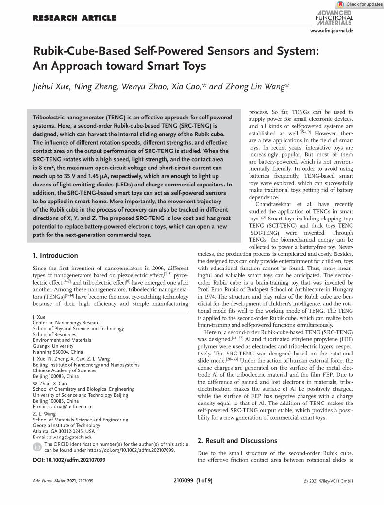
www.afm-journal.de © 2021 Wiley-VCH GmbH 2107099 (1 of 9) 1. Introduction Since the first invention of nanogenerators in 2006, different types of nanogenerators based on piezoelectric effect, [1–3] pyroe- lectric effect, [4–7] and triboelectric effect [8] have emerged one after another. Among these nanogenerators, triboelectric nanogenera- tors (TENGs) [9–14] have become the most eye-catching technology because of their high efficiency and simple manufacturing RESEARCH ARTICLE Rubik-Cube-Based Self-Powered Sensors and System: An Approach toward Smart Toys Jiehui Xue, Ning Zheng, Wenyu Zhao, Xia Cao,* and Zhong Lin Wang* Triboelectric nanogenerator (TENG) is an effective approach for self-powered systems. Here, a second-order Rubik-cube-based TENG (SRC-TENG) is designed, which can harvest the internal sliding energy of the Rubik cube. The influence of different rotation speeds, different strengths, and effective contact area on the output performance of SRC-TENG is studied. When the SRC-TENG rotates with a high speed, light strength, and the contact area is 8 cm 2 , the maximum open-circuit voltage and short-circuit current can reach up to 35 V and 1.45 µA, respectively, which are enough to light up dozens of light-emitting diodes (LEDs) and charge commercial capacitors. In addition, the SRC-TENG-based smart toys can act as self-powered sensors to be applied in smart home. More importantly, the movement trajectory of the Rubik cube in the process of recovery can also be tracked in different directions of X, Y, and Z. The proposed SRC-TENG is low cost and has great potential to replace battery-powered electronic toys, which can open a new path for the next-generation commercial toys. DOI: 10.1002/adfm.202107099 J. Xue Center on Nanoenergy Research School of Physical Science and Technology School of Resources Environment and Materials Guangxi University Nanning 530004, China J. Xue, N. Zheng, X. Cao, Z. L. Wang Beijing Institute of Nanoenergy and Nanosystems Chinese Academy of Sciences Beijing 100083, China W. Zhao, X. Cao School of Chemistry and Biological Engineering University of Science and Technology Beijing Beijing 100083, China E-mail: [email protected] Z. L. Wang School of Materials Science and Engineering Georgia Institute of Technology Atlanta, GA 30332-0245, USA E-mail: [email protected] process. So far, TENGs can be used to supply power for small electronic devices, and all kinds of self-powered systems are established as well. [15–19] However, there are a few applications in the field of smart toys. In recent years, interactive toys are increasingly popular. But most of them are battery-powered, which is not environ- mentally friendly. In order to avoid using batteries frequently, TENG-based smart toys were explored, which can successfully make traditional toys getting rid of battery dependence. Chandrasekhar et al. have recently studied the application of TENGs in smart toys. [20] Smart toys including clapping toys TENG (SCT-TENG) and duck toys TENG (SDT-TENG) were invented. Through TENGs, the biomechanical energy can be collected to power a battery-free toy. Never- theless, the production process is complicated and costly. Besides, the designed toys can only provide entertainment for children, toys with educational function cannot be found. Thus, more mean- ingful and valuable smart toys can be anticipated. The second- order Rubik cube is a brain-training toy that was invented by Prof. Erno Rubik of Budapest School of Architecture in Hungary in 1974. The structure and play rules of the Rubik cube are ben- eficial for the development of children’s intelligence, and the rota- tional mode fits well to the working mode of TENG. The TENG is applied to the second-order Rubik cube, which can realize both brain-training and self-powered functions simultaneously. Herein, a second-order Rubik-cube-based TENG (SRC-TENG) was designed. [21–27] Al and fluorinated ethylene propylene (FEP) polymer were used as electrodes and triboelectric layers, respec- tively. The SRC-TENG was designed based on the rotational slide mode. [28–33] Under the action of human external force, the dense charges are generated on the surface of the metal elec- trode Al of the triboelectric material and the film FEP. Due to the difference of gained and lost electrons in materials, tribo- electrification makes the surface of Al be positively charged, while the surface of FEP has negative charges with a charge density equal to that of Al. The addition of TENG makes the self-powered SRC-TENG output stable, which provides a possi- bility for a new generation of commercial smart toys. 2. Result and Discussions Due to the small structure of the second-order Rubik cube, the effective friction contact area between rotational slides is The ORCID identification number(s) for the author(s) of this article can be found under https://doi.org/10.1002/adfm.202107099. Adv. Funct. Mater. 2021, 2107099
Transcript of Rubik‐Cube‐Based Self‐Powered Sensors and System: An ...
www.afm-journal.de
© 2021 Wiley-VCH GmbH2107099 (1 of 9)
1. Introduction
Since the first invention of nanogenerators in 2006, different types of nanogenerators based on piezoelectric effect,[1–3] pyroe-lectric effect,[4–7] and triboelectric effect[8] have emerged one after another. Among these nanogenerators, triboelectric nanogenera-tors (TENGs)[9–14] have become the most eye-catching technology because of their high efficiency and simple manufacturing
ReseaRch aRticle
Rubik-Cube-Based Self-Powered Sensors and System: An Approach toward Smart Toys
Jiehui Xue, Ning Zheng, Wenyu Zhao, Xia Cao,* and Zhong Lin Wang*
Triboelectric nanogenerator (TENG) is an effective approach for self-powered systems. Here, a second-order Rubik-cube-based TENG (SRC-TENG) is designed, which can harvest the internal sliding energy of the Rubik cube. The influence of different rotation speeds, different strengths, and effective contact area on the output performance of SRC-TENG is studied. When the SRC-TENG rotates with a high speed, light strength, and the contact area is 8 cm2, the maximum open-circuit voltage and short-circuit current can reach up to 35 V and 1.45 µA, respectively, which are enough to light up dozens of light-emitting diodes (LEDs) and charge commercial capacitors. In addition, the SRC-TENG-based smart toys can act as self-powered sensors to be applied in smart home. More importantly, the movement trajectory of the Rubik cube in the process of recovery can also be tracked in different directions of X, Y, and Z. The proposed SRC-TENG is low cost and has great potential to replace battery-powered electronic toys, which can open a new path for the next-generation commercial toys.
DOI: 10.1002/adfm.202107099
J. XueCenter on Nanoenergy ResearchSchool of Physical Science and TechnologySchool of ResourcesEnvironment and MaterialsGuangxi UniversityNanning 530004, ChinaJ. Xue, N. Zheng, X. Cao, Z. L. WangBeijing Institute of Nanoenergy and NanosystemsChinese Academy of SciencesBeijing 100083, ChinaW. Zhao, X. CaoSchool of Chemistry and Biological EngineeringUniversity of Science and Technology BeijingBeijing 100083, ChinaE-mail: [email protected]. L. WangSchool of Materials Science and EngineeringGeorgia Institute of TechnologyAtlanta, GA 30332-0245, USAE-mail: [email protected]
process. So far, TENGs can be used to supply power for small electronic devices, and all kinds of self-powered systems are established as well.[15–19] However, there are a few applications in the field of smart toys. In recent years, interactive toys are increasingly popular. But most of them are battery-powered, which is not environ-mentally friendly. In order to avoid using batteries frequently, TENG-based smart toys were explored, which can successfully make traditional toys getting rid of battery dependence.
Chandrasekhar et al. have recently studied the application of TENGs in smart toys.[20] Smart toys including clapping toys TENG (SCT-TENG) and duck toys TENG (SDT-TENG) were invented. Through TENGs, the biomechanical energy can be collected to power a battery-free toy. Never-
theless, the production process is complicated and costly. Besides, the designed toys can only provide entertainment for children, toys with educational function cannot be found. Thus, more mean-ingful and valuable smart toys can be anticipated. The second-order Rubik cube is a brain-training toy that was invented by Prof. Erno Rubik of Budapest School of Architecture in Hungary in 1974. The structure and play rules of the Rubik cube are ben-eficial for the development of children’s intelligence, and the rota-tional mode fits well to the working mode of TENG. The TENG is applied to the second-order Rubik cube, which can realize both brain-training and self-powered functions simultaneously.
Herein, a second-order Rubik-cube-based TENG (SRC-TENG) was designed.[21–27] Al and fluorinated ethylene propylene (FEP) polymer were used as electrodes and triboelectric layers, respec-tively. The SRC-TENG was designed based on the rotational slide mode.[28–33] Under the action of human external force, the dense charges are generated on the surface of the metal elec-trode Al of the triboelectric material and the film FEP. Due to the difference of gained and lost electrons in materials, tribo-electrification makes the surface of Al be positively charged, while the surface of FEP has negative charges with a charge density equal to that of Al. The addition of TENG makes the self-powered SRC-TENG output stable, which provides a possi-bility for a new generation of commercial smart toys.
2. Result and Discussions
Due to the small structure of the second-order Rubik cube, the effective friction contact area between rotational slides is
The ORCID identification number(s) for the author(s) of this article can be found under https://doi.org/10.1002/adfm.202107099.
Adv. Funct. Mater. 2021, 2107099
www.afm-journal.dewww.advancedsciencenews.com
2107099 (2 of 9) © 2021 Wiley-VCH GmbH
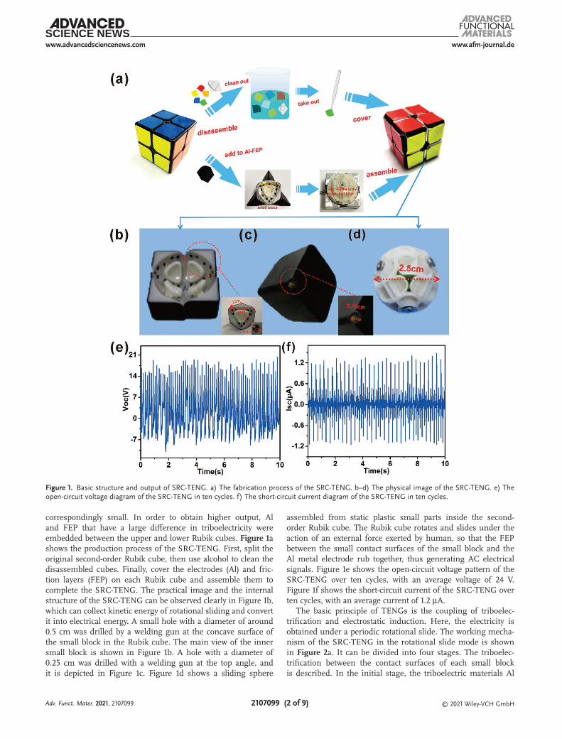
correspondingly small. In order to obtain higher output, Al and FEP that have a large difference in triboelectricity were embedded between the upper and lower Rubik cubes. Figure 1a shows the production process of the SRC-TENG. First, split the original second-order Rubik cube, then use alcohol to clean the disassembled cubes. Finally, cover the electrodes (Al) and fric-tion layers (FEP) on each Rubik cube and assemble them to complete the SRC-TENG. The practical image and the internal structure of the SRC-TENG can be observed clearly in Figure 1b, which can collect kinetic energy of rotational sliding and convert it into electrical energy. A small hole with a diameter of around 0.5 cm was drilled by a welding gun at the concave surface of the small block in the Rubik cube. The main view of the inner small block is shown in Figure 1b. A hole with a diameter of 0.25 cm was drilled with a welding gun at the top angle, and it is depicted in Figure 1c. Figure 1d shows a sliding sphere
assembled from static plastic small parts inside the second-order Rubik cube. The Rubik cube rotates and slides under the action of an external force exerted by human, so that the FEP between the small contact surfaces of the small block and the Al metal electrode rub together, thus generating AC electrical signals. Figure 1e shows the open-circuit voltage pattern of the SRC-TENG over ten cycles, with an average voltage of 24 V. Figure 1f shows the short-circuit current of the SRC-TENG over ten cycles, with an average current of 1.2 µA.
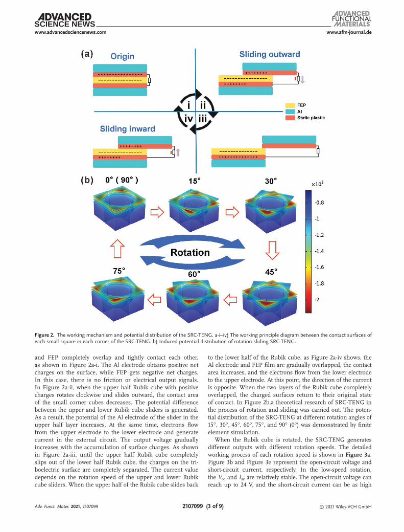
The basic principle of TENGs is the coupling of triboelec-trification and electrostatic induction. Here, the electricity is obtained under a periodic rotational slide. The working mecha-nism of the SRC-TENG in the rotational slide mode is shown in Figure 2a. It can be divided into four stages. The triboelec-trification between the contact surfaces of each small block is described. In the initial stage, the triboelectric materials Al
Figure 1. Basic structure and output of SRC-TENG. a) The fabrication process of the SRC-TENG. b–d) The physical image of the SRC-TENG. e) The open-circuit voltage diagram of the SRC-TENG in ten cycles. f) The short-circuit current diagram of the SRC-TENG in ten cycles.
Adv. Funct. Mater. 2021, 2107099
www.afm-journal.dewww.advancedsciencenews.com
2107099 (3 of 9) © 2021 Wiley-VCH GmbH
and FEP completely overlap and tightly contact each other, as shown in Figure 2a-i. The Al electrode obtains positive net charges on the surface, while FEP gets negative net charges. In this case, there is no friction or electrical output signals. In Figure 2a-ii, when the upper half Rubik cube with positive charges rotates clockwise and slides outward, the contact area of the small corner cubes decreases. The potential difference between the upper and lower Rubik cube sliders is generated. As a result, the potential of the Al electrode of the slider in the upper half layer increases. At the same time, electrons flow from the upper electrode to the lower electrode and generate current in the external circuit. The output voltage gradually increases with the accumulation of surface charges. As shown in Figure 2a-iii, until the upper half Rubik cube completely slips out of the lower half Rubik cube, the charges on the tri-boelectric surface are completely separated. The current value depends on the rotation speed of the upper and lower Rubik cube sliders. When the upper half of the Rubik cube slides back
to the lower half of the Rubik cube, as Figure 2a-iv shows, the Al electrode and FEP film are gradually overlapped, the contact area increases, and the electrons flow from the lower electrode to the upper electrode. At this point, the direction of the current is opposite. When the two layers of the Rubik cube completely overlapped, the charged surfaces return to their original state of contact. In Figure 2b,a theoretical research of SRC-TENG in the process of rotation and sliding was carried out. The poten-tial distribution of the SRC-TENG at different rotation angles of 15°, 30°, 45°, 60°, 75°, and 90° (0°) was demonstrated by finite element simulation.
When the Rubik cube is rotated, the SRC-TENG generates different outputs with different rotation speeds. The detailed working process of each rotation speed is shown in Figure 3a. Figure 3b and Figure 3e represent the open-circuit voltage and short-circuit current, respectively. In the low-speed rotation, the Voc and Isc are relatively stable. The open-circuit voltage can reach up to 24 V, and the short-circuit current can be as high
Figure 2. The working mechanism and potential distribution of the SRC-TENG. a-i–iv) The working principle diagram between the contact surfaces of each small square in each corner of the SRC-TENG. b) Induced potential distribution of rotation-sliding SRC-TENG.
Adv. Funct. Mater. 2021, 2107099

www.afm-journal.dewww.advancedsciencenews.com
2107099 (4 of 9) © 2021 Wiley-VCH GmbH
as 0.6 µA. Figure 3c and Figure 3f show the open-circuit voltage and the short-circuit current, respectively, when the sliding Rubik cube is rotated at a medium speed. The open-circuit voltage and the short-circuit current can reach up to 24 V and 0.8 µA. Figure 3d and Figure 3g show the open-circuit voltage and the short-circuit current, when the SRC-TENG is rotated at a high speed. They can reach up to 35 V and 1.45 µA, respectively.
The open-circuit voltage of the SRC-TENG increases by 11 V and the short-circuit current also increases significantly. The results show that the SRC-TENG has a stable output.
We all know that different people have different strengths when rotating the Rubik cube. However, when we rotate at high speed in the X-direction, applying Rubik cubes with dif-ferent weights in the X-direction is approximately equivalent to
Figure 3. Comparison of output performance of the SRC-TENG at three different speeds. a) Working process of the SRC-TENG system in different states. b,e) The open-circuit voltage and short-circuit current at low-speed rotation. c,f) The open-circuit voltage and the short-circuit current at medium-speed rotation. d,g) The open-circuit voltage and short-circuit current at high rotation speed.
Adv. Funct. Mater. 2021, 2107099
www.afm-journal.dewww.advancedsciencenews.com
2107099 (5 of 9) © 2021 Wiley-VCH GmbH
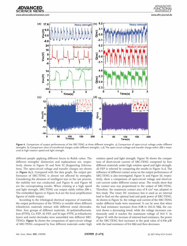
different people applying different forces to Rubik cubes. The different strengths’ distinction and explanations are, respec-tively, shown in Figure S1 and Note S1 (Supporting Informa-tion). The open-circuit voltage and transfer charges are shown in Figure 4a,b. Compared with the data graph, the output per-formance of SRC-TENG is almost not affected by strengths. Considering the abrasion of intelligent toys in the use process, the stability test was conducted, and Figure 4c and Figure 4d are the corresponding results. When rotating at a high speed and light strength, SRC-TENG can output stably within 200 s. The embedded figures in Figure 4c,d are the local amplification figures of stable output.
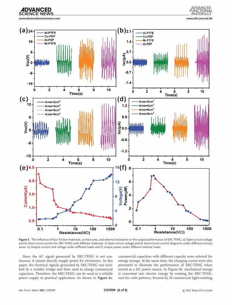
According to the tribological electrical sequence of materials, the output performance of the TENGs is variable when different triboelectric materials interact with different metal electrodes. Here, four groups of different materials, Al–polytetrafluoroety-lene (PTFE), Cu–FEP, Al–FEP, and Ni tape–PTFE, as triboelectric layers and metal electrodes were assembled into different SRC-TENGs. Figure 5a shows the comparison of open-circuit voltage of SRC-TENG composed by four different materials under high
rotation speed and light strength. Figure 5b shows the compar-ison of short-circuit current of SRC-TENG composed by four different materials under high rotation speed and light strength. Al–FEP is selected by comparing the results in Figure 5c,d. The influence of different contact areas on the output performance of SRC-TENG is also investigated. Figure 5c and Figure 5d, respec-tively, show a comparison of open-circuit voltage and short-cir-cuit current under different contact areas. The results show that the contact area was proportional to the output of SRC-TENG. Therefore, the maximum contact area of 8 cm2 was adopted in this study. The rotary DC resistance box is used as an external load to find out the optimal load and peak power of SRC-TENG. As shown in Figure 5e, the voltage and current of the SRC-TENG under different loads were measured. It can be seen that when the load resistance increases from 0.08 to 1111.11 MΩ, the cur-rent shows a decreasing trend, while the voltage increases con-tinuously until it reaches the maximum voltage of 14.0 V. In Figure 5f, with the increase of external load resistance, the power of the SRC-TENG first increases to the peak value of 6.936 µW with the load resistance of 0.6 MΩ and then decreases.
Figure 4. Comparison of output performances of the SRC-TENG at three different strengths. a) Comparison of open-circuit voltage under different strengths. b) Comparison chart of transferred charges under different strengths. c,d) The open-circuit voltage and transfer charge within 200 s meas-ured at high rotation speed and light strength.
Adv. Funct. Mater. 2021, 2107099
www.afm-journal.dewww.advancedsciencenews.com
2107099 (6 of 9) © 2021 Wiley-VCH GmbH
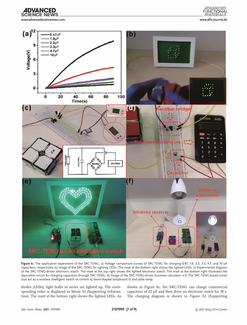
Since the AC signal generated by SRC-TENG is not con-tinuous, it cannot directly supply power for electronics. In this paper, the electrical signals generated by SRC-TENG was recti-fied by a rectifier bridge and then used to charge commercial capacitors. Therefore, the SRC-TENG can be used as a reliable power supply in practical application. As shown in Figure 6a,
commercial capacitors with different capacity were selected for energy storage. At the same time, the charging curves were also presented to illustrate the performance of SRC-TENG when served as a DC power source. In Figure 6b, mechanical energy is converted into electric energy by rotating the SRC-TENG, and the cube patterns, formed by 24 commercial light-emitting
Figure 5. The influence of four friction materials, contact area, and external resistance on the output performance of SRC-TENG. a) Open-circuit voltage and b) short-circuit current for SRC-TENG with different materials. c) Open-circuit voltage and d) short-circuit current diagrams under different contact areas. e) Output current and voltage under different loads and f) output power under different external loads.
Adv. Funct. Mater. 2021, 2107099
www.afm-journal.dewww.advancedsciencenews.com
2107099 (7 of 9) © 2021 Wiley-VCH GmbH
diodes (LEDs), light bulbs in series are lighted up. The corre-sponding video is displayed in Movie S1 (Supporting Informa-tion). The inset at the bottom right shows the lighted LEDs. As
shown in Figure 6c, the SRC-TENG can charge commercial capacitors of 22 µF and then drive an electronic watch for 18 s. The charging diagram is shown in Figure S2 (Supporting
Figure 6. The application experiment of the SRC-TENG. a) Voltage comparison curves of SRC-TENG for charging 0.47, 1.0, 2.2, 3.3, 4.7, and 10 µF capacitors, respectively. b) Image of the SRC-TENG for lighting LEDs. The inset at the bottom right shows the lighted LEDs. c) Experimental diagram of the SRC-TENG-driven electronic watch. The inset at the top right shows the lighted electronic watch. The inset at the bottom right illustrates the equivalent circuit for charging capacitors through SRC-TENG. d) Image of the SRC-TENG-driven business calculator. e,f) The SRC-TENG-based smart toys act as a wireless intelligent switch to control e) heart-shaped lampboard f) and table lamp.
Adv. Funct. Mater. 2021, 2107099
www.afm-journal.dewww.advancedsciencenews.com
2107099 (8 of 9) © 2021 Wiley-VCH GmbH
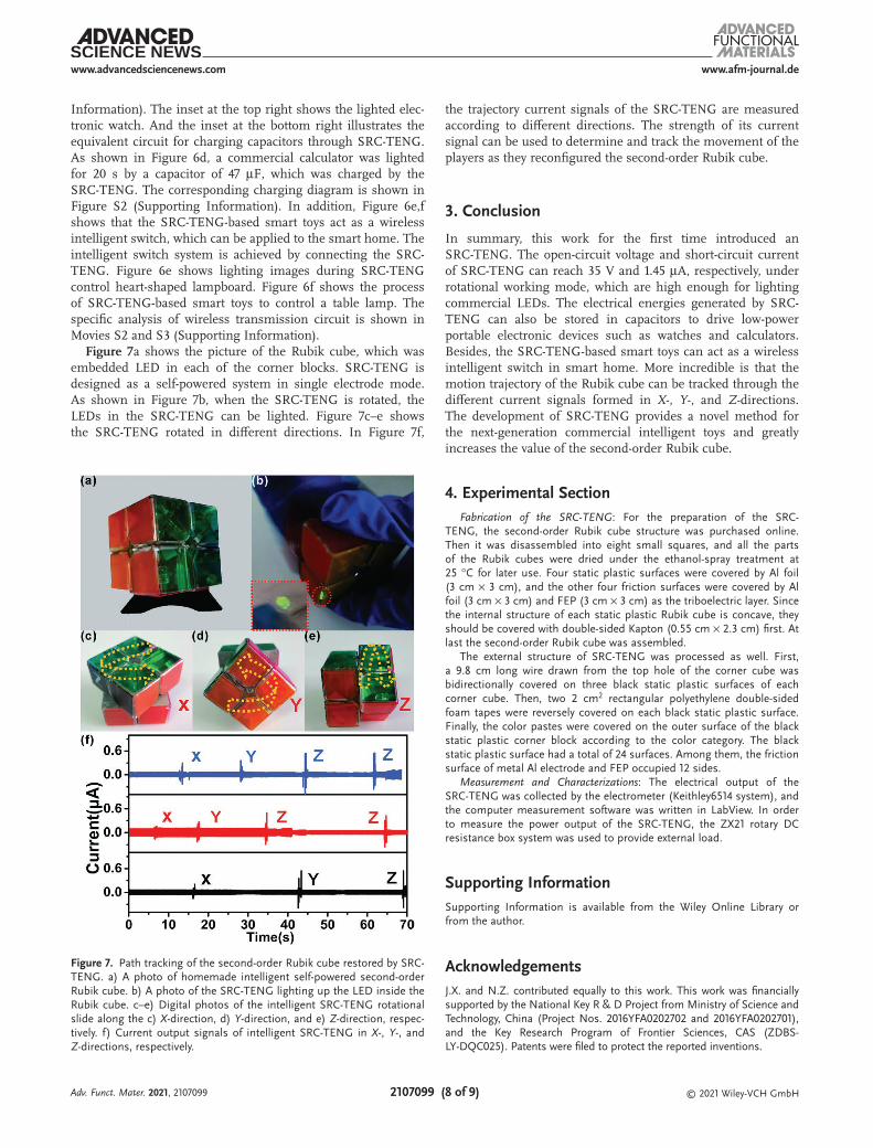
Information). The inset at the top right shows the lighted elec-tronic watch. And the inset at the bottom right illustrates the equivalent circuit for charging capacitors through SRC-TENG. As shown in Figure 6d, a commercial calculator was lighted for 20 s by a capacitor of 47 µF, which was charged by the SRC-TENG. The corresponding charging diagram is shown in Figure S2 (Supporting Information). In addition, Figure 6e,f shows that the SRC-TENG-based smart toys act as a wireless intelligent switch, which can be applied to the smart home. The intelligent switch system is achieved by connecting the SRC-TENG. Figure 6e shows lighting images during SRC-TENG control heart-shaped lampboard. Figure 6f shows the process of SRC-TENG-based smart toys to control a table lamp. The specific analysis of wireless transmission circuit is shown in Movies S2 and S3 (Supporting Information).Figure 7a shows the picture of the Rubik cube, which was
embedded LED in each of the corner blocks. SRC-TENG is designed as a self-powered system in single electrode mode. As shown in Figure 7b, when the SRC-TENG is rotated, the LEDs in the SRC-TENG can be lighted. Figure 7c–e shows the SRC-TENG rotated in different directions. In Figure 7f,
the trajectory current signals of the SRC-TENG are measured according to different directions. The strength of its current signal can be used to determine and track the movement of the players as they reconfigured the second-order Rubik cube.
3. Conclusion
In summary, this work for the first time introduced an SRC-TENG. The open-circuit voltage and short-circuit current of SRC-TENG can reach 35 V and 1.45 µA, respectively, under rotational working mode, which are high enough for lighting commercial LEDs. The electrical energies generated by SRC-TENG can also be stored in capacitors to drive low-power portable electronic devices such as watches and calculators. Besides, the SRC-TENG-based smart toys can act as a wireless intelligent switch in smart home. More incredible is that the motion trajectory of the Rubik cube can be tracked through the different current signals formed in X-, Y-, and Z-directions. The development of SRC-TENG provides a novel method for the next-generation commercial intelligent toys and greatly increases the value of the second-order Rubik cube.
4. Experimental SectionFabrication of the SRC-TENG: For the preparation of the SRC-
TENG, the second-order Rubik cube structure was purchased online. Then it was disassembled into eight small squares, and all the parts of the Rubik cubes were dried under the ethanol-spray treatment at 25 °C for later use. Four static plastic surfaces were covered by Al foil (3 cm × 3 cm), and the other four friction surfaces were covered by Al foil (3 cm × 3 cm) and FEP (3 cm × 3 cm) as the triboelectric layer. Since the internal structure of each static plastic Rubik cube is concave, they should be covered with double-sided Kapton (0.55 cm × 2.3 cm) first. At last the second-order Rubik cube was assembled.
The external structure of SRC-TENG was processed as well. First, a 9.8 cm long wire drawn from the top hole of the corner cube was bidirectionally covered on three black static plastic surfaces of each corner cube. Then, two 2 cm2 rectangular polyethylene double-sided foam tapes were reversely covered on each black static plastic surface. Finally, the color pastes were covered on the outer surface of the black static plastic corner block according to the color category. The black static plastic surface had a total of 24 surfaces. Among them, the friction surface of metal Al electrode and FEP occupied 12 sides.
Measurement and Characterizations: The electrical output of the SRC-TENG was collected by the electrometer (Keithley6514 system), and the computer measurement software was written in LabView. In order to measure the power output of the SRC-TENG, the ZX21 rotary DC resistance box system was used to provide external load.
Supporting InformationSupporting Information is available from the Wiley Online Library or from the author.
AcknowledgementsJ.X. and N.Z. contributed equally to this work. This work was financially supported by the National Key R & D Project from Ministry of Science and Technology, China (Project Nos. 2016YFA0202702 and 2016YFA0202701), and the Key Research Program of Frontier Sciences, CAS (ZDBS-LY-DQC025). Patents were filed to protect the reported inventions.
Figure 7. Path tracking of the second-order Rubik cube restored by SRC-TENG. a) A photo of homemade intelligent self-powered second-order Rubik cube. b) A photo of the SRC-TENG lighting up the LED inside the Rubik cube. c–e) Digital photos of the intelligent SRC-TENG rotational slide along the c) X-direction, d) Y-direction, and e) Z-direction, respec-tively. f) Current output signals of intelligent SRC-TENG in X-, Y-, and Z-directions, respectively.
Adv. Funct. Mater. 2021, 2107099
www.afm-journal.dewww.advancedsciencenews.com
2107099 (9 of 9) © 2021 Wiley-VCH GmbH
Conflict of InterestThe authors declare no conflict of interest.
Data Availability StatementResearch data are not shared.
KeywordsRubik cube, self-powered system, smart toy, triboelectric nanogenerator
Received: July 21, 2021Revised: September 28, 2021
Published online:
[1] Q. Zhu, L. Dong, J. Zhang, K. Xu, Y. Zhang, H. Shi, H. Lu, Y. Wu, H. Zheng, Z. Wang, Ceram. Int. 2020, 46, 28277.
[2] S. K. Karan, S. Maiti, J. H. Lee, Y. K. Mishra, B. B. Khatua, J. K. Kim, Adv. Funct. Mater. 2020, 30, 2004446.
[3] D. Heo, J. Chung, B. Kim, H. Yong, G. Shin, J.-W. Cho, D. Kim, S. Lee, Nano Energy 2020, 72, 104719.
[4] Z. Li, Z. Qiang, Z. Wang, Z. Li, Research 2020, 2020, 8710686.[5] H. You, X. Ma, Z. Wu, L. Fei, X. Chen, J. Yang, Y. Liu, Y. Jia, H. Li,
F. Wang, H. Huang, Nano Energy 2018, 52, 351.[6] L. Zhang, N. Zhang, Y. Yang, S. Xiang, C. Tao, S. Yang, X. Fan,
ACS Appl. Mater. Interfaces 2018, 10, 30819.[7] M.-H. You, X.-X. Wang, Y. Xu, J. Zhang, W.-Z. Song, M. Yu, Z. Fan,
S. Ramakrishna, Y.-Z. Long, J. Mater. Chem. A 2018, 6, 3500.[8] W. Wu, T. Yang, Y. Zhang, F. Wang, Q. Nie, Y. Ma, X. Cao,
Z. L. Wang, N. Wang, L. Zhang, ACS Nano 2019, 13, 8202.[9] N. Wang, J. Zou, Y. Yang, X. Li, Y. Guo, C. Jiang, X. Jia, X. Cao, Nano
Energy 2018, 55, 541.[10] X. Cao, Y. Jie, N. Wang, Z. Wang, Adv. Energy Mater. 2016, 6,
1600665.[11] T. Jiang, H. Pang, J. An, P. Lu, Y. Feng, X. Liang, W. Zhong,
Z. L. Wang, Adv. Energy Mater. 2020, 10, 2000064.[12] Z. L. Wang, ACS Nano 2013, 7, 9533.
[13] D. Jiang, B. Shi, H. Ouyang, Y. Fan, Z. L. Wang, Z. Li, ACS Nano 2020, 14, 6436.
[14] Q. Tang, M.-H. Yeh, G. Liu, S. Li, J. Chen, Y. Bai, L. Feng, M. Lai, K.-C. Ho, H. Guo, C. Hu, Nano Energy 2018, 47, 74.
[15] G. Khandelwal, M. K. Ediriweera, N. Kumari, N. P. Maria Joseph Raj, S. K. Cho, S. J. Kim, ACS Appl. Mater. Interfaces 2021, 13, 18887.
[16] W. Zhang, Y. Zhang, G. Yang, X. Hao, X. Lv, F. Wu, J. Liu, Y. Zhang, Nano Energy 2021, 82, 105769.
[17] W. Shang, G. Gu, W. Zhang, H. Luo, T. Wang, B. Zhang, J. Guo, P. Cui, F. Yang, G. Cheng, Z. Du, Nano Energy 2021, 82, 105725.
[18] H. Guo, J. Wan, H. Wang, H. Wu, C. Xu, L. Miao, M. Han, H. Zhang, Research 2021, 2021, 4689869.
[19] I. Merino-Jimenez, A. Llorella, M. Navarro-Segarra, J. Agramunt, A. Grandas, S. D. Minteer, J. P. Esquivel, N. Sabaté, Adv. Mater. Technol. 2021, 6, 2001051.
[20] A. Chandrasekhar, G. Khandelwal, N. Alluri, V. Vivekananthan, S.-J. Kim, ACS Sustainable Chem. Eng. 2018, 6, 6110.
[21] Y. He, X. Zhang, S. Wang, J. Meng, Y. Sui, F. Wei, J. Qi, Q. Meng, Y. Ren, D. Zhuang, J. Alloys Compd. 2020, 847, 156312.
[22] D. Li, P. Jia, J. Li, D. Zhang, X. Kong, Chin. J. Mech. Eng. 2020, 33, 81.
[23] S.-Y. Lin, S.-Y. Chien, C.-L. Hsiao, C.-H. Hsia, K.-M. Chao, Electron. Commer. Res. Appl. 2020, 44, 101011.
[24] M. Akdeniz, F. Özdinç, Int. J. Child-Comput. Interact. 2021, 29, 100347.
[25] F. Zhang, S. Sun, C. Liu, V. Chang, Electron. Commer. Res. Appl. 2020, 41, 100974.
[26] N. Kara, K. Cagiltay, Electron. Commer. Res. Appl. 2020, 39, 100909.[27] E. Lavanya, N. Kalaivani, S. Chinnapparaj, N. K. Mozhi, Mater.
Today: Proc. 2021, 37, 2803.[28] H. Zhang, C. Zhang, J. Zhang, L. Quan, H. Huang, J. Jiang,
S. Dong, J. Luo, Nano Energy 2019, 61, 442.[29] W. Zhang, D. Diao, K. Sun, X. Fan, P. Wang, Nano Energy 2018, 48,
456.[30] Z. Lin, B. Zhang, H. Zou, Z. Wu, H. Guo, Y. Zhang, J. Yang,
Z. L. Wang, Nano Energy 2020, 68, 104378.[31] C. Zhao, Q. Zhang, W. Zhang, X. Du, Y. Zhang, S. Gong, K. Ren,
Q. Sun, Z. L. Wang, Nano Energy 2019, 57, 440.[32] Y. Bai, X. Liang, S. Lin, J. Luo, H. Qin, K. Han, Z. Wang, Adv. Energy
Mater. 2020, 10, 2000605.[33] Z. Qu, R. Dai, L. Wu, Y. An, L. Chen, Y. Xie, Q. Wang, S. Jin,
Z. Wang, W. Yin, Nano Energy 2020, 76, 105075.
Adv. Funct. Mater. 2021, 2107099