RTL Test Justification and Propagation Analysis for Modular ...
16
JOURNAL OF ELECTRONIC TESTING: Theory and Applications 13, 105–120 (1999) c 1999 Kluwer Academic Publishers. Manufactured in The Netherlands. RTL Test Justification and Propagation Analysis for Modular Designs * YIORGOS MAKRIS AND ALEX ORAILO ˘ GLU Reliable Systems Synthesis Lab, CSE Department MC-0114, UCSD, La Jolla, CA 92093 [email protected] [email protected] Received March 23, 1998; Revised June 25, 1998 Editor: N. Jha Abstract. Modular decomposition and functional abstraction are commonly employed to accommodate the grow- ing size and complexity of modern designs. In the test domain, a divide-and-conquer type of approach is utilized, wherein test is locally generated for each module and consequently translated to global design test. We present an RTL analysis methodology that identifies the test justification and propagation bottlenecks, facilitating a judicious DFT insertion process. We introduce two mechanisms for capturing, without reasoning on the complete functional space, data and control module behavior related to test translation. A traversal algorithm that identifies the test trans- lation bottlenecks in the design is described. The algorithm is capable of handling cyclic behavior, reconvergence and variable bit-widths in an efficient manner. We demonstrate our scheme on representative examples, unveiling its potential of accurately identifying and consequently minimizing the reported controllability and observability bottlenecks of large, modular designs. Keywords: RTL testability analysis, test justification, test propagation, modular design, DFT 1. Introduction The latest silicon manufacturing technology improve- ments have facilitated an explosion in the size and complexity of modern designs. Consequently, extreme challenges are imposed on tools and methodologies employed in the design and test of complex, digital cir- cuits. No panacea solution exists, capable of address- ing these challenges in an efficient, universal fashion. Furthermore, test has emerged as the most expensive and threatening burden in a circuit design cycle, re- vealing the imperative need for test-related innovative solutions. As a result, a vast number of techniques and ap- proaches have been developed, both for enhancing the testability of a design through DFT modifications and for improving the test generation and application * This work is supported in part by a research grant from Intel Corporation and the University of California MICRO program. process [1–7]. The nontrivial task of deciding the exact test framework for each design is left to the test engi- neer. DFT related decisions have to be made as early in the design cycle as possible, yet without compromising their cost-effectiveness. In order to select judiciously among the wide variety of choices, a priori testability information of the design is required [8–10]. Acquir- ing such test knowledge for a design is the objective of testability analysis, but its applicability scope has been limited so far, by a number of challenges arising in modern designs. The enormous size of modern circuits rules out test approaches that address the complete design as a mono- lithic entity. State of the art practices for large designs employ both modular decomposition and functional ab- straction in order to alleviate test problems. Gate-level ATPG is applied at each module boundary for efficient local test generation, while higher description levels are utilized for the translation of local into global test. Consequently, any viable test analysis methodology
Transcript of RTL Test Justification and Propagation Analysis for Modular ...

P1: SYD
JOURNAL OF ELECTRONIC TESTING: Theory and Applications KL656-05-Makris October 26, 1998 17:3
JOURNAL OF ELECTRONIC TESTING: Theory and Applications 13, 105–120 (1999)c© 1999 Kluwer Academic Publishers. Manufactured in The Netherlands.
RTL Test Justification and Propagation Analysis for Modular Designs∗
YIORGOS MAKRIS AND ALEX ORAILOGLUReliable Systems Synthesis Lab, CSE Department MC-0114, UCSD, La Jolla, CA 92093
Received March 23, 1998; Revised June 25, 1998
Editor: N. Jha
Abstract. Modular decomposition and functional abstraction are commonly employed to accommodate the grow-ing size and complexity of modern designs. In the test domain, adivide-and-conquertype of approach is utilized,wherein test is locally generated for each module and consequently translated to global design test. We present anRTL analysis methodology that identifies the test justification and propagation bottlenecks, facilitating a judiciousDFT insertion process. We introduce two mechanisms for capturing, without reasoning on the complete functionalspace, data and control module behavior related to test translation. A traversal algorithm that identifies the test trans-lation bottlenecks in the design is described. The algorithm is capable of handling cyclic behavior, reconvergenceand variable bit-widths in an efficient manner. We demonstrate our scheme on representative examples, unveilingits potential of accurately identifying and consequently minimizing the reported controllability and observabilitybottlenecks of large, modular designs.
Keywords: RTL testability analysis, test justification, test propagation, modular design, DFT
1. Introduction
The latest silicon manufacturing technology improve-ments have facilitated an explosion in the size andcomplexity of modern designs. Consequently, extremechallenges are imposed on tools and methodologiesemployed in the design and test of complex, digital cir-cuits. No panacea solution exists, capable of address-ing these challenges in an efficient, universal fashion.Furthermore, test has emerged as the most expensiveand threatening burden in a circuit design cycle, re-vealing the imperative need for test-related innovativesolutions.
As a result, a vast number of techniques and ap-proaches have been developed, both for enhancingthe testability of a design through DFT modificationsand for improving the test generation and application
∗This work is supported in part by a research grant from IntelCorporation and the University of California MICRO program.
process [1–7]. The nontrivial task of deciding the exacttest framework for each design is left to the test engi-neer. DFT related decisions have to be made as early inthe design cycle as possible, yet without compromisingtheir cost-effectiveness. In order to select judiciouslyamong the wide variety of choices, a priori testabilityinformation of the design is required [8–10]. Acquir-ing such test knowledge for a design is the objectiveof testability analysis, but its applicability scope hasbeen limited so far, by a number of challenges arisingin modern designs.
The enormous size of modern circuits rules out testapproaches that address the complete design as a mono-lithic entity. State of the art practices for large designsemploy both modular decomposition and functional ab-straction in order to alleviate test problems. Gate-levelATPG is applied at each module boundary for efficientlocal test generation, while higher description levelsare utilized for the translation of local into global test.Consequently, any viable test analysis methodology

P1: SYD
JOURNAL OF ELECTRONIC TESTING: Theory and Applications KL656-05-Makris October 26, 1998 17:3
106 Makris and Orailoglu
needs to take into consideration the modular nature ofIC designs and emerging test approaches, in order toprove applicable and provide meaningful data.
Due to the strict requirements of a typical circuit,testability enhancements need to be introduced as earlyin the design cycle as possible. Additionally, cost-effective DFT decisions require a more global under-standing of the design than a gate-level analysis mayprovide. The high-level information available at be-havioral RTL descriptions addresses both circuit sizeproblems and design cycle constraints. As a result, RTLis the most effective level for performing testabilityanalysis and guiding DFT modifications.
Large datapaths, intricate control and complex se-quential logic are common features of modern designs,imposing additional burdens on testability analysis.Any attempt to reason exhaustively upon the completefunctional space in a value-by-value manner, using tra-ditional behavior capturing mechanisms such as FSMsand BDDs, is unlikely to succeed. Consequently, a ju-dicious way of pruning to a restricted set of test-relatedbehavior is necessitated. Temporal reasoning and han-dling complex control logic remain essential parts ofsuch test related behavior.
Section 2 motivates the research being outlined, pre-senting a test framework for large, modularly designedcircuits that the analysis methodology targets. Previ-ous work in the area is discussed and associated chal-lenges pinpointed. Section 3 provides an overview ofthe proposed scheme. Sections 4 through 7 present de-tails of the four components of the proposed scheme.These four sections discuss the identification of the testtranslation requirements and the test translation relatedbehavior of each module, the traversal of the design fortest translation requirement satisfaction and the mini-mization of the reported bottlenecks. Section 8 demon-strates the proposed methodology on example circuits,while Section 9 presents the experimental validationflow and outlines the obtained results.
Our research aims at providing an early testabilityassessment of large, modularly designed circuits, ca-pable of reasoning on both combinational and sequen-tial logic. Within our scheme, data and control pathlogic is handled in a uniform fashion, exploiting thetwo mechanisms for capturing test translation relatedbehavior. The goal of the analysis is the identificationof RTL testability bottlenecks associated with test jus-tification and propagation. Since the ultimate objectiveof this work is to guide design testability enhancementsin an informed manner, test translation bottlenecks arecaptured in the signal entity domain that resembles thestructural nature of most DFT modifications.
2. Research Motivation
Size and complexity considerations impede the abilityof test generation tools to handle large designs as single,monolithic entities. We describe a framework that fa-cilitates an effective test methodology, commonly em-ployed in real designs. Within this framework, we de-fine the objectives of the proposed testability analysismethodology. We refer to previous research efforts inthe area and discuss associated challenges.
2.1. Problem Definition
Our work targets large modular designs and addressesone module at a time. A common framework employedfor testing such designs utilizes local test generationwithin each module and subsequent translation of thelocal test into test patterns and responses meaningfulat chip pinouts. During test application, each mod-ule is tested individually, while the remaining modulesare grouped into upstream test justification logic anddownstream test propagation logic. Test is initiated atthe primary inputs and terminated at the primary out-puts. Feedback loops may result in overlaps betweenthe module under test, the justification logic and thepropagation logic. This test framework is depicted inFig. 1.
While a gate-level test generation process at eachmodule boundary proves efficient, translation of localinto global test endangers and limits the applicability ofthe above framework. Several reasons can be quotedas the primary factors for the limited success of thetest translation process. During local test generation,global design capabilities are not taken into account,thus leading to nontranslatable test. Furthermore, the
Fig. 1. Test framework.

P1: SYD
JOURNAL OF ELECTRONIC TESTING: Theory and Applications KL656-05-Makris October 26, 1998 17:3
RTL Test Justification and Propagation Analysis for Modular Designs 107
potential overlap between the module under test, andthe justification and propagation logic may degrade thelocally generated test efficiency. The worst problem,however, is the complexity of the translation processitself, even in the absence of the above constraints. Ex-haustive reasoning on the complete functional space ofthe design, so as to translate the local test in a vector-by-vector fashion, is of equivalent complexity to globaldesign test generation. Therefore, mechanisms foridentifying and utilizing only test translation relatedbehavior for justifying and propagating test symboli-cally, are required.
Looking at the problem from a temporal point ofview, the latest point for useful analysis in supportof DFT is the RTL. As shown in Fig. 2, the analysisobjective is to identify the bottlenecks that DFT modi-fications will be required to resolve. Strict time-to-market requirements and excessive complexity prohibitany reasoning at lower levels. Consequently, the analy-sis methodology needs to employ symbolic, bulk modereasoning, instead of vector-by-vector translation, inorder to pinpoint the test translation bottlenecks. In-evitably, due to the inability to reason exhaustivelyupon the design functionality, some locally generatedtests will not be translated into global tests.
Any locally testable fault that remains uncoveredafter the translation of the local into global test can beclassified as either of the following two types.
1. A fault for which the local test generator, due tolack of global design knowledge, selected a non-translatable test vector. Disabling therandom-fillphase of a test generator can help moderate this ef-fect. Furthermore, in order to eliminate this prob-lem, a methodology was proposed in [6], whereinthe global design capabilities are captured in termsof constraintsand are examined during the local testgeneration. However, extracting these constraints
Fig. 2. Temporal view of analysis objective.
requires reasoning on the complete functional spaceof the global design and is as difficult as to globaltest generation.
2. A fault that is untestable at the global design bound-ary. While the typical case for untestable faults isthought to be functional redundancies, we need toinclude herein faults that cannot be tested due tocomputational complexity limits encountered dur-ing test translation. In this case, DFT hardware isutilized to provide accessibility paths to the bound-ary of the modules for supporting the translation [3,5, 7]. However, an indiscriminate provision of suchaccessibility paths to the boundary of each moduleis overly expensive. DFT modifications for enhanc-ing the test translation process need to be guided byan analysis methodology that will pinpoint the testtranslation bottlenecks. Consequently, judiciousand cost-effective DFT insertion will be facilitatedfor eliminating these bottlenecks.
2.2. Related Work
Several researchers have identified the benefits of com-bining functional abstraction and modular decomposi-tion, in order to assure improved testability of largedesigns. Among them, Murray and Hayes [11] pro-posed a test result propagation scheme through mod-ules based onambiguity sets. Vishakantaiah et al. [10]presented a test knowledge extraction methodology forhierarchical designs, wherein behavioral capabilities ofthe modules are extracted in terms ofmodes. Ghoshet al. [3] presented a similar DFT and test generationtechnique for core-based systems, based on thecon-trol/data flow graph. Hansen and Hayes [12] describeda high-level test generation scheme for modular de-signs, utilizing a functional fault model ofphysicallyinduced faultsandsymbolic schedulingto alleviate thelarge search space. Recently, Tupuri and Abraham [6]introduced a functional test generation method for em-bedded modules by incorporating the test justificationand propagation capabilities of the surrounding logicinto the test generation process in the form ofcon-straints. Also, Chen et al. [1], Corno et al. [8] and Leeand Patel [9], suggested various general approaches foraddressing behavioral and RTL testability analysis.
2.3. Challenges
Several challenges are associated with the task ofidentifying test translation bottlenecks. Relying on the

P1: SYD
JOURNAL OF ELECTRONIC TESTING: Theory and Applications KL656-05-Makris October 26, 1998 17:3
108 Makris and Orailoglu
justification and propagation of the exact vectors andresponses for identifying test translation bottlenecks isoverly expensive. The complexity of doing the trans-lation itself would make such an approach unpalatable.Furthermore, any changes in the actual test set, wouldinvalidate the analysis results. Identification of a set ofsufficient symbolic test justification and propagationrequirements for each module, coupled with an anal-ysis of the design as to its capability to satisfy theserequirements, possibly offers a solution. An identifi-cation of independent cones of logic, as discussed inSection 4, is suggested as a heuristic approach in thisdirection.
Further challenges are associated with the local toglobal test translation. We discuss and demonstratethem in Fig. 3, on a small, complex circuit, originallypresented in [10].
• Exhaustive examination of the complete functionalspace of the modules in the design can be highlyexpensive. Large datapaths (e.g., 16-bit adder), se-quential logic (e.g., 212 states of the 12-bit counter)and intermodule complex behavior (e.g., feedbackfrom OUT to the adder) prohibit exhaustive func-tional reasoning during the translation. Therefore,the challenge is to identify a subset of the completefunctional space that is tolerable in terms of complex-ity and that captures the most common test transla-tion behavioral features. In the example of Fig. 3,utilizing the LD capability of the counter for justi-fying values to the rest of the circuit eliminates theneed to reason upon the complex counter FSM. InSection 5, we describe two mechanisms for captur-ing test translation related behavior.• Identification of the appropriate domain for examin-
ing the design is a second challenge. In our example,
Fig. 3. Illustrative example for test translation challenges.
reasoning on the output of the adder can be per-formed either through arithmetic values or throughbit-wise signal entities. Choosing between the valuedomain and the signal domain is a critical decision.The value domain allows exploitation of arithmeticproperties while the signal domain supports complexcontrol logic and variable bit-widths. Our schemeexamines both attributes, in a structural manner thatresembles the nature of most DFT techniques.• Modular traversal does not necessitate the use of the
complete word width. For example, while propa-gating the counter’s test responses over the adder inFig. 3, we only need to reason on the sub-word thatcomprises the lowest 12 bits. An efficient schemerequires handling of dynamic changes in the signalbit-width.• Such dynamic variance impedes the a priori extrac-
tion of module transparency behavior. The connec-tivity model of the complete design and the testrequirements need to be taken into account. For ex-ample, the fact that one of the inputs of the addersplits into a 4-bit and a 12-bit signal hints that weneed to be able to extracton-the-flytransparency be-havior for these signal bit-widths.• Sequential logic, reconvergent paths and feedback
loops generate further challenges. In Fig. 3, se-quences of two vectors are necessary in order to testthe register, creating a cycle. Moreover, the feed-back line from the adder’s OVF to the counter’s CLRsignal, along with the FSM behavior of the counter,compose a complicated sequential logic that is diffi-cult to capture. Handling sequential logic and cyclicbehavior is an inseparable part of a viable test trans-lation analysis scheme.Any divide-and-conquertype of methodology, such
as the module-by-module test translation analysis, im-poses the challenge of combining and sharing the dis-tributed results. In our case, the challenge is to min-imize the reported bottlenecks by identifying the rootcauses that can be shared among multiple modules.The sequence in which the modules are examined andthe local traversal decisions can have a crucial impacton the final results. As this minimization problem iscomputationally taxing, we propose two heuristics, inSection 7, that attempt to address this challenge.
3. Methodology Overview
As depicted in Fig. 4, our analysis methodology ad-dresses the aforementioned challenges in four steps,discussed in the following sections. Initially, the test

P1: SYD
JOURNAL OF ELECTRONIC TESTING: Theory and Applications KL656-05-Makris October 26, 1998 17:3
RTL Test Justification and Propagation Analysis for Modular Designs 109
Fig. 4. Analysis methodology overview.
translation requirements are identified for each modulein the design. Since actual test and responses are notavailable during analysis, we rely on a simple heuris-tic that attempts to ease the overkill of justifying andpropagating any possible vector and response. Basedon the cone-of-logic of each input and output, a setof justification and propagation requirements on signalentities are extracted, as explained in Section 4. Us-ing these signal entities and the connectivity model ofthe complete design, we then identify the test transla-tion related behavior of each module. This behavior iscaptured in one of two ways, described in Section 5.
Consequently, a traversal algorithm is applied to theboundary of each module. The algorithm attempts tosatisfy the test justification and propagation require-ments, using only the test translation related behaviorof the modules in the design. The details of the traver-sal algorithm and the heuristics employed are furtherdiscussed in Section 6. Finally, in order to minimizethe reported bottlenecks, a heuristic for combining bot-tlenecks between modules is applied as described inSection 7.
4. Test Requirement Identification
Since actual test vectors and responses are not knownat the time of analysis, the most naive way is to requirejustification and propagation of every possible valueand response to and from the boundary of each mod-ule. For sequential modules, reasoning upon sequencesof vectors and responses needs to be considered. For amodule of sequential depthk, we will requirek+ 1 con-secutive patterns and responses to fully test the module.
Justification and propagation of every possible vectorand response can be avoided based on a simple heuris-tic. We suggest in that context the identification of thecone of logic driven by each input and into each output.
This input/output mapping is an indication of thedecomposability of the module, through which the de-pendent sets of inputs and outputs can be extracted andused for defining more realistic requirements. In eithercase, the requirements need to be expressed in a col-lective form and not in a value by value manner. Ourheuristic captures these requirements in a stream-wisefashion, employing signal entities of variable bit-width.To demonstrate this, we examine the cones of logic inthe 4-bit register of Fig. 5.
The register has sequential depth of 1. Consequently,two consecutive patterns are needed to test it. Sinceeach output OUT[k] is driven only by two signals (CLRand IN[k]), the justification requirements are to get any
Fig. 5. Requirement identification heuristic.

P1: SYD
JOURNAL OF ELECTRONIC TESTING: Theory and Applications KL656-05-Makris October 26, 1998 17:3
110 Makris and Orailoglu
two values on consecutive clock cycles on any 2-bit sig-nal entity (CLK, IN[k]). This is a looser requirementthan justifying any two values in consecutive clock cy-cles on the complete 5-bit input signal entity (CLR,IN[1], IN[2], IN[3], IN[4]). On the other hand, sincethe CLR signal drives all outputs, the propagation re-quirements are the translation in a distinguishable man-ner of any value at the complete 4-bit signal entity(OUT[1], OUT[2], OUT[3], OUT[4]).
5. Test Translation Related Behavior
Identification of the test translation requirements isfollowed by a capture of the test translation relatedbehavior of each module. This behavior is utilizedfor examining the satisfiability of the requirementsand identifying the bottlenecks. As discussed inSection 2, exhaustive examination of the completefunctional space cannot be tolerated due to complex-ity issues. Therefore, we rely on capturing only testtranslation related behavior for each module and utili-zing only this behavior for test justification and propa-gation. Although this scheme sacrifices some of thebehavioral space, it provides the ability to reason on thetranslation capabilities of the design in an automatedfashion.
We have developed two schemes for capturing testtranslation related behavior. The first scheme is basedon arithmetic properties of modules and targets mainlydatapath modules. The second scheme is an elabora-tion on the first scheme, based on channels (bijectionfunctions) that can address uniformly data and controlpath modules and that can handle variable bit-widthsignal entities. These two schemes are introduced inthis section.
5.1. Property-Based Scheme
The basic concept underlying our property-basedscheme is the utilization of arithmetic properties thatcan provide a simple transparency mechanism overmodules. Test requirements are translated in bulkmode, using the algebraic scheme that these arithmeticproperties compose. The arithmetic properties do notcapture the complete functional space of the modulesbut rather the types of behavior that will be most prob-ably used for test translation.
Using this type of behavior, requirements at the inputsignal entities of a module are translated to equivalent
Fig. 6. Property-based scheme examples.
requirements at the output signal entities of the mod-ule and vice versa. The new requirements are possiblyrelated through operators and are based on the satisfi-ability of a number of conditions, as demonstrated inFig. 6. Only test translation related behavior of modulesis considered for requirement translation. In a simi-lar fashion, condition compliance examination is basedon the same property combination scheme. The typesof properties that our scheme considers include iden-tity, linearity, negation, initialization and incremental-ity. The operators used for combining these proper-ties are both in the arithmetic domain (e.g.,+, *, <,=, >) and in the structural path domain (e.g., logicalAND, NOT, OR). The arithmetic property scheme iscapable of handling both combinational and sequentialmodules since timing is captured as part of the proper-ties, as demonstrated on the 4-bit counter.
The arithmetic property scheme for capturing testtranslation related behavior of modules proves efficientfor datapath designs, addressing combinational andsequential modules. It facilitates an algebraic schemethat not only can reason on whether a translation isfeasible but also may guide the translation itself. How-ever, a number of reasons limit its applicability. Controllogic, usually, does not exhibit such arithmetic proper-ties and therefore cannot be handled therein. Further-more, reasoning on sub-word, variable bit entities isnot simple through the arithmetic properties and rela-tions between different width signal entities are not cap-tured. Also, using this algebraic reasoning, bottlenecksare identified and reported in the value domain, whilemost DFT modifications are structural. Furthermore,

P1: SYD
JOURNAL OF ELECTRONIC TESTING: Theory and Applications KL656-05-Makris October 26, 1998 17:3
RTL Test Justification and Propagation Analysis for Modular Designs 111
the interpretation between the two domains is not al-ways trivial. The above problems have necessitateda more elaborate scheme, capable of addressing themefficiently.
5.2. Channel-Based Scheme
A behavioral formalism that addresses the above chal-lenges is presented and demonstrated on simple exam-ple modules, followed by a discussion of its potential.The transparency aspects of the modules are capturedin a structural manner through the notion ofchannels.Controllability and observability are captured throughthe notions ofwell and drain. This scheme handlesvariable bit-width signals through thesignal entityno-tion and facilitates an efficient mechanism capable ofhandling uniformly, based onconditionsand opera-tors, combinational or sequential, data or control pathmodules.
5.2.1. Behavioral Formalism. The components ofthe behavioral formalism are defined below.
Channel: A channelis defined to be amappingbe-tween an inputsignal entityand an outputsignal entityor between awell and an output signal entity or be-tween an input signal entity and adrain, based on thecompliance of a set of zero or moreconditions.Mapping: A mappingis defined as a one-to-one andonto function from the set of possible values of an inputsignal entityor awell, to the set of possible values ofan outputsignal entityor adrain.Signal Entity: A signal entityrepresents a bundle ofone or more signals at a certain point in time. Both thesignals and the time point can be defined either stati-cally or dynamically. Dynamic definition is a collec-tive way of capturing many static definitions, allowingmore flexibility and generality. As an example, a staticdefinition of a signal entity might beIN[2] at [t] whilea dynamic definition would look likeONE OF IN[3],IN[2] , IN[1] at any t where t> t0. The dynamic defi-nition can be a choice from either a list of alternativesor from a closed type set definition.Well: A well is the equivalent of a controllability pointand captures the ability of a module to generate vectorson signal entities. It also captures the controllability ofthe primary inputs. Each well has associated with it apotentialon signal entities.Drain: A drain is the equivalent of an observabilitypoint and captures the ability of a module to evaluate
vectors on signal entities. It also captures the observ-ability of the primary outputs. Each drain has associ-ated with it apotentialon signal entities.Potential: Thepotentialof a well or a drain capturesthe type of vectors that can be generated or evaluatedon a signal entity. For example, a full potential well ofwidth k can generate the complete set of all possible 2k
vectors and a full potential drain of widthk can evaluatelikewise the complete set. The potential of a well or adrain is not defined in the value domain but rather in thesignal domain. This implies that a well cannot gener-ate a set of specific values unless a structural propertydefining the elements of the set in the signal domain(e.g., mutual exclusion, same, inverse) exists. Thesesets are captured in a stream-wise manner, avoidingthe complete functional space complexity problem.Conditions: Conditionsare defined on one or more in-put signal entities and are combined throughoperators.In order for a channel to be activated, the conditionsassociated with it need to be satisfied.Operators: Operatorsbetween signal entities are em-ployed to create the above conditions. These oper-ators can be either logical (e.g., AND, OR) stream-related (e.g., INDEPENDENT OF) or arithmetic (e.g.,=, 6=,≤,≥). The only requirement is that they haveto be expressed in a stream-wise fashion, since this isthe rule for our behavior capturing mechanism. Thelatter point amplifies the fact that we cannot afford toperform directly a value-based analysis but instead weimplicitly imitate it through a more generic, stream-wise reasoning.Time-Extended Channels:A time-extended channel ofdepth kis a sequence ofk channels instantiated inkconsecutive clock cycles, with respect either to the in-put or the output signal entity.
5.2.2. Examples. A number of examples of basicRTL modules together with some of their channels areshown in Fig. 7, displaying how the behavioral formal-ism is used for capturing module traversal capabilities.These capabilities will be utilized by the design traver-sal methodology described in Section 6, in order toexamine the satisfiability of the test justification andpropagation requirements of each module.
5.2.3. Scheme Evaluation. The following pointsaddress the strengths of the behavioral formalism, sum-marizing its potential.
• The behavioral formalism that we introduced con-stitutes an abstraction scheme that decouples the

P1: SYD
JOURNAL OF ELECTRONIC TESTING: Theory and Applications KL656-05-Makris October 26, 1998 17:3
112 Makris and Orailoglu
Fig. 7. Channel-based scheme examples.
module traversal capability extraction and the actualDFT modification process from testability analysis,providing a clean interfacing mechanism betweenthem. Consequently, each of these tasks can be in-dividually addressed.• Although it does not cover the complete behavioral
space of the modules, it handles variable bit-widthsof input and output signal entities through the welland drain notions and applies not only at the full wordsize but also on sub-word signal entities. The abil-ity of the channels to express any arbitrary bijectionfunction brings our scheme as close to the conceptof transparency as possible.• There is more than one way to describe a traversal
through channels. Extracting all the channels in ad-vance is not practical. A similar problem limits theapproaches described in [9, 10]. In order to addressthis issue, we rely on anon-the-flychannel selection
for our test justification and propagation analysis, asexplained further in the traversal algorithm.• The time-extended channels provide a capability to
reason on sequences of vectors and responses, thusfacilitating sequential logic testability analysis. Thisproves valuable in case a clock disable signal is notprovided for sequential modules.
In short, the introduced formalism provides a con-cise and efficient way to capture behavior related totest justification and propagation, in a structural man-ner. In conjunction with the structural nature of DFTtechniques, it facilitates a realistic testability analysismethodology that identifies the test translation bottle-necks as described in Section 6.
5.2.4. Handling Control Modules. Control logic, ingeneral, does not exhibit the same type of transparency
P1: SYD
JOURNAL OF ELECTRONIC TESTING: Theory and Applications KL656-05-Makris October 26, 1998 17:3
RTL Test Justification and Propagation Analysis for Modular Designs 113
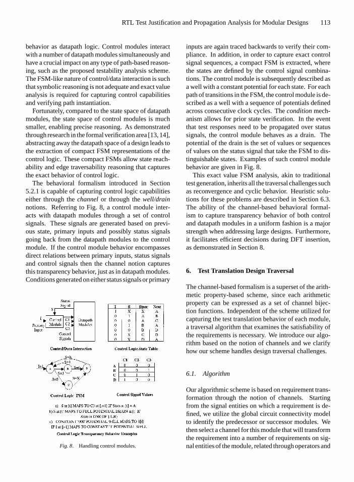
behavior as datapath logic. Control modules interactwith a number of datapath modules simultaneously andhave a crucial impact on any type of path-based reason-ing, such as the proposed testability analysis scheme.The FSM-like nature of control/data interaction is suchthat symbolic reasoning is not adequate and exact valueanalysis is required for capturing control capabilitiesand verifying path instantiation.
Fortunately, compared to the state space of datapathmodules, the state space of control modules is muchsmaller, enabling precise reasoning. As demonstratedthrough research in the formal verification area [13, 14],abstracting away the datapath space of a design leads tothe extraction of compact FSM representations of thecontrol logic. These compact FSMs allow state reach-ability and edge traversability reasoning that capturesthe exact behavior of control logic.
The behavioral formalism introduced in Section5.2.1 is capable of capturing control logic capabilitieseither through thechannelor through thewell/drainnotions. Referring to Fig. 8, a control module inter-acts with datapath modules through a set of controlsignals. These signals are generated based on previ-ous state, primary inputs and possibly status signalsgoing back from the datapath modules to the controlmodule. If the control module behavior encompassesdirect relations between primary inputs, status signalsand control signals then the channel notion capturesthis transparency behavior, just as in datapath modules.Conditions generated on either status signals or primary
Fig. 8. Handling control modules.
inputs are again traced backwards to verify their com-pliance. In addition, in order to capture exact controlsignal sequences, a compact FSM is extracted, wherethe states are defined by the control signal combina-tions. The control module is subsequently described asa well with a constant potential for each state. For eachpath of transitions in the FSM, the control module is de-scribed as a well with a sequence of potentials definedacross consecutive clock cycles. Theconditionmech-anism allows for prior state verification. In the eventthat test responses need to be propagated over statussignals, the control module behaves as a drain. Thepotential of the drain is the set of values or sequencesof values on the status signal that take the FSM to dis-tinguishable states. Examples of such control modulebehavior are given in Fig. 8.
This exact value FSM analysis, akin to traditionaltest generation, inherits all the traversal challenges suchas reconvergence and cyclic behavior. Heuristic solu-tions for these problems are described in Section 6.3.The ability of the channel-based behavioral formal-ism to capture transparency behavior of both controland datapath modules in a uniform fashion is a majorstrength when addressing large designs. Furthermore,it facilitates efficient decisions during DFT insertion,as demonstrated in Section 8.
6. Test Translation Design Traversal
The channel-based formalism is a superset of the arith-metic property-based scheme, since each arithmeticproperty can be expressed as a set of channel bijec-tion functions. Independent of the scheme utilized forcapturing the test translation behavior of each module,a traversal algorithm that examines the satisfiability ofthe requirements is necessary. We introduce our algo-rithm based on the notion of channels and we clarifyhow our scheme handles design traversal challenges.
6.1. Algorithm
Our algorithmic scheme is based on requirement trans-formation through the notion of channels. Startingfrom the signal entities on which a requirement is de-fined, we utilize the global circuit connectivity modelto identify the predecessor or successor modules. Wethen select a channel for this module that will transformthe requirement into a number of requirements on sig-nal entities of the module, related through operators and

P1: SYD
JOURNAL OF ELECTRONIC TESTING: Theory and Applications KL656-05-Makris October 26, 1998 17:3
114 Makris and Orailoglu
Fig. 9. Design traversal algorithm.
based on a number of conditions. If these conditionsare satisfied then the process is repeated for the new re-quirements. Otherwise, a new channel is chosen. Eachsearch path terminates when the requirements are sat-isfied through well or drain capabilities or when thereare no more alternative channels to consider, in whichcase the nonsatisfiable signal entities are reported asbottlenecks. In Fig. 9 we provide a pseudocode formrecursive description of the proposed algorithm.
The conditions that the channels generate whentraversing modules are also expressed as requirementsand the same algorithm is applied to examine theirsatisfiability. Since conditions are typically harder tosatisfy, for backtracking minimization we examinethem first. Further information regarding the algorithmshown can be found for the aspects depicted in bold-face in Fig. 9. Thus,requirement identificationisdescribed in Section 4,channel selectionbetween pos-sible alternatives examined in the current section andmodule selectionandbottleneck combinationdiscussedin Section 7.
6.2. Channel Selection Decision Factors
Selecting judiciously among the alternative channelsor combination of channels that satisfy a requirementover a module has a significant impact on the amountof backtracking performed. A greedy approach,best
Fig. 10. Channel selection example.
match first, is currently employed but only after a num-ber ofdecision factorsare examined. These factors areeither static or dynamic. Static factors are extractedfrom the circuit connectivity model and include thenumber of signal entities and conditions involved ina channel and its latency in number of clock cycles.Dynamic factors capture the maximum potential thathas been satisfied on each signal entity and the for-mation of loops or reconvergent paths in the searchspace.
In Fig. 10, an example is given where two alterna-tive channels can justify the output of the module undertest. The upper channel has a latency of three clock cy-cles, involves two signal entities of total width sevenand creates one condition on a 2-bit signal entity. Itfurther causes a reconvergent path in the search spacewhen module A is reached. The lower channel has a la-tency of two clock cycles, involves two signal entities oftotal width six and creates one condition on a 1-bit sig-nal entity. Also, a feedback loop from module E iscreated. In this case, both channels are rated as equallydifficult. Hence, the decision would be made based onthe dynamic factors capturing the maximum require-ment previously satisfied on each of the two alternativechannels, through modules B and D.
6.3. Feedback Loops and Reconvergence
Our scheme utilizes the cyclic behavior caused by feed-back loops for requirement transformation over mod-ules. Potential cycles are identified from the connec-tivity model and local analysis is performed. Channelsthat create loops are only selected when local analysisidentifies a potential loop exit point, within an upperbound of iterations. Channels that create reconvergentpaths are also identified from the connectivity model.To address this problem, multiple paths are followedin parallel and channel selection is postponed until theconvergence point.

P1: SYD
JOURNAL OF ELECTRONIC TESTING: Theory and Applications KL656-05-Makris October 26, 1998 17:3
RTL Test Justification and Propagation Analysis for Modular Designs 115
7. Bottleneck Combination
The proposed traversal algorithm identifies the control-lability and observability bottlenecks for each module.Due to dynamic factors affecting local decisions duringrequirement satisfiability examination, the sequence inwhich the modules are considered has a critical im-pact on the final number of bottlenecks reported. Fur-thermore, the same bottleneck might solve translationproblems for more than one module. Examining themodules in all possible sequences is computationallyhighly expensive. In order to address this problem, twoheuristics are proposed, as outlined below.
The first heuristic gives the order in which the mod-ules should be examined for justification and propa-gation requirement satisfiability. We assume that eachsignal entity in our design is an equiprobable bottleneckand we calculate the number of signal entities involvedin examining each module. At each point, we exam-ine the module that shares the maximum number ofsignal entities with the rest of the modules. Maximiza-tion of the number of signal entities with an associateddynamic factor is thus attained, after examining eachmodule in the above sequence. Also, we expect thatresolving the identified bottlenecks for a module willresolve possible bottlenecks for other modules, mini-mizing the total number of reported bottlenecks. Thescheme is repeated until all the modules are examined.Individual orderings are derived for propagation andjustification analysis.
The problem is easily formulated as afind all pathsgraph problem, where each module is a node and eachsignal entity a weighted edge according to the signalentity width. Primary inputs and primary outputs arealso considered as nodes. In Fig. 11, a simple exampleis given, along with the consequent ordering. Justifica-tion analysis starts from module E, since it requires 12signals, out of which eight are also required by other
Fig. 11. Module ordering heuristic.
Fig. 12. Bottleneck combination heuristic.
modules (B and D), the maximum number of sharedsignals. Similarly, propagation analysis starts frommodule B since it requires 15 signals, out of which nineare also required for other modules (A, C, D and E),again the maximum number of shared signals.
Since our first heuristic relies on a probabilistic as-sumption on potential bottlenecks, we also employ asecond heuristic depicted in Fig. 12, which attempts tominimize the actual bottlenecks reported. During thefirst analysis phase of the heuristic, modules are exam-ined in the order determined by the primary moduleordering heuristic. Bottlenecks identified for a modulek are considered resolved when we examine a subse-quent modulei with i > k. With all reported bottle-necks from the first phase considered resolved, we runa second analysis phase in the same module order andthus obtain a new set of bottlenecks. The bottlenecksfrom both phases are subsequently combined and amix& match type of algorithm eliminates the redundantones. Although this scheme does not ensure the maxi-mum amount of bottleneck sharing, it has significantlydecreased the number of reported bottlenecks in ourexperiments.
8. Examples
We demonstrate our testability analysis methodologyon two example circuits. The first circuit is a sign-magnitude 8-bit binary multiplier described in [15].The arithmetic property scheme has been applied onthe circuit datapath portion. In Fig. 13, a circuit blockdiagram is depicted. The justification analysis at the

P1: SYD
JOURNAL OF ELECTRONIC TESTING: Theory and Applications KL656-05-Makris October 26, 1998 17:3
116 Makris and Orailoglu
Fig. 13. Property-based analysis example on a binary sign-magnitude multiplier.

P1: SYD
JOURNAL OF ELECTRONIC TESTING: Theory and Applications KL656-05-Makris October 26, 1998 17:3
RTL Test Justification and Propagation Analysis for Modular Designs 117
output bus is provided. The propagation analysis is sim-ilar. The circuit is highly transparent and no majorbottlenecks have been identified. The few minor bot-tlenecks are also reported in the figure. As a result, weexpect the test translation process to be very efficientfor this circuit.
The control logic handling mechanism of Section5.2.4 is applied on the multiplier controller, as shownalso in Fig. 13. The normal operation FSM provideseight control signals to the datapath and has five states,requiring three state elements for encoding. When theabove analysis is applied concurrently to both the data-path and the controller, taking into account the FSMbehavior, an additional controllability bottleneck isidentified on one of the state-encoding signals. Thereason for this is that false paths may need to be uti-lized during the test translation, requiring illegal statesor transitions in the controller. Furthermore, a trade-offbottleneck on a second state-encoding signal has beenidentified. More specifically, the ability to bypass thecontroller loop S1-S2-S1 decreases the test time foreach vector by 14 clock cycles, at the additional costof one more controllability bottleneck to be resolved.Such trade-off data can facilitate cost-effective DFTmodifications.
The second circuit is a pipelined multiplier accu-mulator described in behavioral and RTL VHDL in[16]. The circuit is mainly datapath oriented and com-prises combinational and sequential modules, feedbackloops, reconvergent paths and variable bit-widths anda small control-like logic for the overflow calculation.In Fig. 14, we show the results of our channel-basedscheme applied on this circuit. Justification analysis forthe register REG22#1 and propagation analysis for themultiplier MUL#4 are provided in detail. The resultsof our module ordering heuristic for justification andpropagation are shown and the complete set of testa-bility bottlenecks identified through our methodologyreported.
9. Experimental Validation
The proposed methodology for test justification andpropagation analysis identifies the potential control-lability and observability bottlenecks in the RTL de-sign. This section describes the experimental valida-tion framework employed for examining the analysisaccuracy. Furthermore, results on the above examplecircuits are presented.
9.1. Validation Flow
An overview of the validation flow is provided inFig. 15. In compliance with the test framework forwhich the analysis methodology has been derived, ourprimary validation mechanism utilizes HITEC [17], agate-level ATPG tool and is based on fault coveragecomparison acquired from the fault simulator PROOFS[18]. Starting with an RTL description of the circuit,the described analysis methodology is applied, result-ing in a list of controllability and observability bottle-necks. A gate-level model is further obtained throughsynthesis, on which the ATPG experiments are per-formed.
First, the ATPG tool is applied independently foreach design module, resulting in local tests. Each localtest is subsequently translated to the boundaries of thecomplete circuit and global test is obtained and faultsimulated to provide the associated global fault cover-age (GFC). The same experiment is then performed onan enhanced version of the design, wherein all the jus-tification and propagation bottlenecks identified by theanalysis are considered to be fully controllable or ob-servable. The modified GFC, shown in the final columnof the table of Fig. 15, is thus obtained. The underly-ing translation of the local to global test is manuallyperformed.
9.2. Results
We applied the above experimental flow on TC100, thecircuit of Fig. 3, the binary multiplier with and with-out the controller, and the pipelined multiplier accu-mulator described in the previous section. The analy-sis methodology indicated that TC100 and the binarymultiplier without the controller are highly transpar-ent and that no major test translation bottlenecks existin the design. Consequently, we expect translation oflocal into global test to be highly successful. Sum-ming up the total faults covered by the local tests anddividing by the local number of faults, we obtained96.68% and 97.45% coverage, respectively. After thelocal test was translated to design boundary test, cov-erage dropped slightly to 92.80% and 93.27%, dueto the few minor bottlenecks. A new translation af-ter bottleneck resolution through test point insertionincreased the coverage to 95.74% and 96.65%, indi-cating that our methodology identified accurately thebottlenecks of the test translation process. When the

P1: SYD
JOURNAL OF ELECTRONIC TESTING: Theory and Applications KL656-05-Makris October 26, 1998 17:3
118 Makris and Orailoglu
Fig. 14. Channel-based analysis example on a pipelined multiplier accumulator (MAC).

P1: SYD
JOURNAL OF ELECTRONIC TESTING: Theory and Applications KL656-05-Makris October 26, 1998 17:3
RTL Test Justification and Propagation Analysis for Modular Designs 119
Fig. 15. Experimental validation flow and results.
controller of the multiplier was also considered, thecorresponding loss of coverage due to the test trans-lation bottlenecks was considerably larger, resultingin a drop from 94.52% to 68.46%. Such precipitousfault coverage drops stem from the fact that the con-troller effects multiple modules. Resolving the bottle-necks almost eliminated the translation problems, ascan be seen by the drastically increased coverage of90.64%.
In the case of the MAC, our analysis identified nu-merous justification and propagation bottlenecks in thedesign. The coverage dropped from 96.44% achievedby the local tests to 70.22% achieved by the translatedtest on the original circuit. After the bottlenecks wereresolved, the coverage of the new translated test in-creased to 91.35%, validating the accuracy of the re-ported bottlenecks.
The results are summarized in Fig. 15. The faultsthat remained uncovered after bottleneck resolutionwere identified to belong to the multiplexers that wereused for inserting test points. Except from these faultsthat do not belong to the original circuit, our analy-sis methodology has identified precisely the test trans-lation bottlenecks, as indicated by the above results.Further experiments on larger circuits are currently car-ried out, in order to demonstrate the scalability of ourscheme.
10. Conclusion
We have introduced an efficient testability analysismethodology for large, modular designs. We addressthe challenges associated with the common test frame-work employed in testing such designs, where testis locally generated at module boundaries and conse-quently translated to test stimuli applicable at pinouts.In order to avoid the common complexity pitfall oflarge designs, we have developed two mechanisms forcapturing test translation related behavior of modules.A traversal algorithm has been described that examinesthe satisfiability of the test justification and propaga-tion requirements at each module’s boundary, basedon this behavior.
Our methodology handles in a uniform way bothcombinational and sequential, data and control pathmodules. Furthermore, it addresses problems relatedto the traversal process, such as feedback loops and re-convergent paths. The test translation bottlenecks areidentified in a structural manner and combined amongmodules. The accuracy of our methodology has beendemonstrated and validated experimentally on exam-ple circuits, proving its potential to guide efficient testengineering decisions. Our future research plans com-prise a concise decision-making mechanism for en-hancing the testability of a design. More specifically,

P1: SYD
JOURNAL OF ELECTRONIC TESTING: Theory and Applications KL656-05-Makris October 26, 1998 17:3
120 Makris and Orailoglu
the identified bottlenecks can pinpoint appropriate DFTmodifications such as in [3, 5, 7], support the bindingphase of high-level test synthesis in a fashion similarto [4], or direct a logic synthesis tool as in [1], in orderto provide additional test translation capabilities.
References
1. C-H. Chen, T. Karnik, and D.G. Saab, “Structural and Behav-ioral Synthesis for Testability Techniques,”IEEE Transactionson CAD of Integrated Circuits and Systems, Vol. 13, No. 6, pp.777–785, June 1994.
2. I. Ghosh, A. Raghunathan, and N.K. Jha, “A Design for Testabil-ity Technique for RTL Circuits using Control/Data Flow Extrac-tion,” Proc. IEEE/ACM International Conference on ComputerAided Design, 1996, pp. 329–336.
3. I. Ghosh, N. Jha, and S. Dey, “A Low-Overhead Design for Testa-bility and Test Generation Technique for Core-Based Systems,”Proc. International Test Conference, 1997, pp. 50–59.
4. A. Orailoglu and I. Harris, “Microarchitectural Synthesis forRapid BIST Testing,”IEEE Transactions on CAD of IntegratedCircuits and Systems, Vol. 6, No. 6, pp. 573–586, June 1997.
5. B. Pouya and N. Touba, “Modifying User-Defined Logic forTest Access to Embedded Cores,”Proc. International Test Con-ference, 1997, pp. 60–68.
6. R.S. Tupuri and J.A. Abraham, “A Novel Test GenerationMethod for Processors using Commercial ATPG,”Proc. Inter-national Test Conference, 1997, pp. 743–752.
7. P. Vishakantaiah, T. Thomas, J.A. Abraham, and M.S. Abadir,“AMBIANT: Automatic Generation of Behavioral Modifica-tions for Testability,”Proc. IEEE International Conference onComputer Design, 1993, pp. 63–66.
8. F. Corno, P. Prinetto, and M. Sonza Reorda, “Testability Analysisand ATPG on Behavioral RT-Level VHDL,”Proc. InternationalTest Conference, 1997, pp. 753–759.
9. J. Lee and J. Patel, “Testability Analysis Based on Structural andBehavioral Information,”Proc. 11th IEEE VLSI Test Symposium,1993, pp. 139–145.
10. P. Vishakantaiah, J.A. Abraham, and M.S. Abadir, “AutomaticTest Knowledge Extraction from VHDL (ATKET),”Proc. 29thACM/IEEE Design Automation Conference, 1992, pp. 273–278.
11. B.T. Murray and J.P. Hayes, “Test Propagation Through Modulesand Circuits,”Proc. International Test Conference, 1991, pp.748–757.
12. M.C. Hansen and J.P. Hayes, “High-Level Test Generation Us-ing Symbolic Scheduling,”Proc. International Test Conference,1995, pp. 586–595.
13. K.T. Cheng and A.S. Krishnakumar, “Automatic Functional TestGeneration using the Extended Finite State Machine Model,”Proc. 30th ACM/IEEE Design Automation Conference, 1992,pp. 86–91.
14. D. Moundanos, J.A. Abraham, and Y.V. Hoskote, “A UnifiedFramework for Design Validation and Manufacturing Test,”Proc. International Test Conference, 1996, pp. 875–884.
15. J.P. Hayes,Computer Architecture and Organization, 3rd edi-tion, McGraw-Hill, 1998.
16. P. Ashenden,The Designer’s Guide to VHDL, 1st edition,Morgan-Kaufmann Publishers Inc., 1996.
17. T. Niermann and J. Patel, “HITEC: A Test Generation Packagefor Sequential Circuits,”Proc. European Conference on DesignAutomation, 1992, pp. 214–218.
18. T. Niermann, W.T. Cheng, and J. Patel, “PROOFS: A Fast, Mem-ory Efficient Sequential Circuit Fault Simulator,”Proc. 27thACM/IEEE Design Automation Conference, 1990, pp. 535–540.
Yiorgos Makris received the Diploma of Computer Engineering andInformatics from the University of Patras, Greece, in 1995 and theM.S. degree in Computer Engineering from the University of Cali-fornia, San Diego, in 1997. He is currently working towards his Ph.D.degree in Computer Engineering, at the University of California,San Diego. His research interests include testability analysis, testgeneration and DFT.
Alex Orailo glu received the S.B. degree from Harvard College,cumlaude, in Applied Mathematics in 1977. He received the M.S. degreein Computer Science from the University of Illinois, Urbana, in 1979,and the Ph.D. degree in Computer Science from the University ofIllinois, Urbana, in 1983. Prof. Orailo˘glu has been a member of thefaculty of the Computer Science and Engineering Department at theUniversity of California, San Diego, since 1987. Prof. Orailo˘glu’sresearch interests include the high-level synthesis of fault-tolerantmicroarchitectures, and the synthesis of testable designs.