RTL Functional Test Generation using Factored Concolic ...RTL Functional Test Generation using...
74
RTL Functional Test Generation using Factored Concolic Execution Sonal Pinto Thesis submitted to the Faculty of the Virginia Polytechnic Institute and State University in partial fulfillment of the requirements for the degree of Master of Science in Computer Engineering Michael S. Hsiao, Chair Haibo Zeng Patrick R. Schaumont June 1, 2017 Blacksburg, Virginia Keywords: Functional Test Generation, Control-Flow Response, Concolic Execution, Branch Coverage, System State Copyright 2017, Sonal Pinto
Transcript of RTL Functional Test Generation using Factored Concolic ...RTL Functional Test Generation using...

RTL Functional Test Generation using Factored ConcolicExecution
Sonal Pinto
Thesis submitted to the Faculty of theVirginia Polytechnic Institute and State University
in partial fulfillment of the requirements for the degree of
Master of Sciencein
Computer Engineering
Michael S. Hsiao, ChairHaibo Zeng
Patrick R. Schaumont
June 1, 2017Blacksburg, Virginia
Keywords: Functional Test Generation, Control-Flow Response, Concolic Execution,Branch Coverage, System State
Copyright 2017, Sonal Pinto

RTL Functional Test Generation using Factored Concolic Execution
Sonal Pinto
(ABSTRACT)
This thesis presents a novel concolic testing methodology and CORT, a test generation
framework that uses it for high-level functional test generation. The test generation effort is
visualized as the systematic unraveling of the control-flow response of the design over mul-
tiple (factored) explorations. We begin by transforming the Register Transfer Level (RTL)
source for the design into a high-performance C++ compiled functional simulator which
is instrumented for branch coverage. An exploration begins by simulating the design with
concrete stimuli. Then, we perform an interleaved cycle-by-cycle symbolic evaluation over
the concrete execution trace extracted from the Control Flow Graph (CFG) of the design.
The purpose of this task is to dynamically discover means to divert the control flow of the
system, by mutating primary-input stimulated control statements in this trace. We record
the control-flow response as a Test Decision Tree (TDT), a new representation for the test
generation effort. Successive explorations begin at system states heuristically selected from
a global TDT, onto which each new decision tree resultant from an exploration is stitched.
CORT succeeds at constructing functional tests for ITC99 and IWLS-2005 benchmarks that
achieve high branch coverage using the fewest number of input vectors, faster than exist-
ing methods. Furthermore, we achieve orders of magnitude speedup compared to previous
hybrid concrete and symbolic simulation based techniques.
This work was supported in part by the DARPA CRAFT Verification Task (DARPA-BAA-
15-55) and the National Science Foundation Project 1422054.

RTL Functional Test Generation using Factored Concolic Execution
Sonal Pinto
(GENERAL AUDIENCE ABSTRACT)
In recent years, the cost of verifying digital designs has outpaced the cost of development, in
terms of both resources and time. The scale and complexity of modern designs have made
it increasingly impractical to manually verify the design. In the process of circuit design,
designers use Hardware Descriptive Languages (HDL) to abstract the design in a manner
similar to software programming languages. This thesis presents a novel methodology for
the automation of testing functional level hardware description with the aim of maximizing
branch coverage. Branches indicate decision points in the design, and tests with high branch
coverage are able to thoroughly exercise the design in a manner that randomly generated
tests cannot. In our work, the design is simulated concretely with a random test (a sequence
of input or stimulus). During simulation, we analyze the flow of behavioral statements
and decisions executed to construct a formulaic interpretation of the design execution in
terms of syntactical elements, to uncover differentiating input that could have diverted the
flow of execution to unstimulated parts of the design. This process is formally known as
Concolic Execution. The techniques described in this thesis tightly interleaves concrete and
symbolic simulation (concolic execution) of hardware designs to generate tests with high
branch coverage, orders of magnitude faster than previous similar work.

∼ To my family ∼
iv

Acknowledgments
This work would be incomplete without acknowledging the guidance and support of those
who made it possible. To begin with, I owe my greatest thanks to my research mentor, Dr.
Michael S. Hsiao for granting me the opportunity to engage in invigorating research and to
participate as his research assistant. His excellent course on "Electronic Design Automation"
in Spring 2016 piqued my curiosity and inspired me to pursue my Master’s thesis under his
tutelage. Throughout the span of the work that went into this thesis, he tirelessly guided and
polished my work with his extensive background and experience in the field. I am honored
to have received a chance to work with him.
I would like to thank Dr. Haibo Zeng and Dr. Patrick Schaumont for graciously agreeing to
serve on my thesis committee. I also thank the administrative staff of the Graduate School
and the Bradley Department of Electrical and Computer Engineering for their timely help
and continued cooperation with paperwork and other administrative matters.
I am thankful to my friends in the PROACTIVE Research Group for enriching my graduate
school experience: Tonmoy Roy, Kunal Bansal, Yue Zhan, Aravind V., Tania Khanna and
ChungHa Sung. I am especially grateful to Tonmoy for his patience in engaging me in my
animated narrations of knowledge that I gleaned from the research literature. He introduced
me to the complex domain of symbolic execution in hardware and entertained every query I
had on the topic.
v

I thank Shobek Sam, Shobal Sam, Shriya Shah, Nahush Gondhalekar, Harsh Patel and Ak-
shatha Kini for indeed making my graduate school experience unforgettable. I am thankful
for the love and support of my family, without whom I would not even have had the oppor-
tunity to experience a fulfilling graduate school life at Virginia Tech. Lastly, I am thankful
to my loving fiancee, Rohita Darga, for believing in me, and being my ultimate pillar of
support and ensuring that I didn’t starve.
Sonal Pinto
Blacksburg
June 1, 2017
vi
Contents
List of Figures ix
List of Tables x
List of Algorithms xi
1 Introduction 1
1.1 Contributions of this Thesis . . . . . . . . . . . . . . . . . . . . . . . . . . . 2
1.2 Thesis Organization . . . . . . . . . . . . . . . . . . . . . . . . . . . . . . . . 4
2 Background 5
2.1 Automated Functional Test Generation . . . . . . . . . . . . . . . . . . . . . 5
2.2 Concolic Execution . . . . . . . . . . . . . . . . . . . . . . . . . . . . . . . . 8
2.3 Scaling through Factored Exploration . . . . . . . . . . . . . . . . . . . . . . 10
2.4 Verilator and RTL Instrumentation . . . . . . . . . . . . . . . . . . . . . . . 15
2.5 Related Work . . . . . . . . . . . . . . . . . . . . . . . . . . . . . . . . . . . 17
3 Cycle-by-Cycle Concolic Execution of RTL 20
3.1 Terminology . . . . . . . . . . . . . . . . . . . . . . . . . . . . . . . . . . . . 21
3.2 Preprocessing and Instrumentation . . . . . . . . . . . . . . . . . . . . . . . 23
3.2.1 Concrete Trace Recording . . . . . . . . . . . . . . . . . . . . . . . . 23
3.2.2 RTL Translation and Analysis . . . . . . . . . . . . . . . . . . . . . . 24
3.3 RTL Concolic Execution . . . . . . . . . . . . . . . . . . . . . . . . . . . . . 27
vii

3.3.1 Two-Pass Simulation . . . . . . . . . . . . . . . . . . . . . . . . . . . 27
3.3.2 Dynamic discovery and mutation of Activated Guards . . . . . . . . . 29
3.3.3 Iterative Bounded Explorations . . . . . . . . . . . . . . . . . . . . . 31
3.4 Experimentation and Results . . . . . . . . . . . . . . . . . . . . . . . . . . 31
3.4.1 Experiment Setup . . . . . . . . . . . . . . . . . . . . . . . . . . . . . 32
3.4.2 Branch Coverage . . . . . . . . . . . . . . . . . . . . . . . . . . . . . 33
3.4.3 Test Generation Runtime . . . . . . . . . . . . . . . . . . . . . . . . 34
4 Test Generation using Factored Explorations 35
4.1 Test Decision Tree . . . . . . . . . . . . . . . . . . . . . . . . . . . . . . . . 36
4.2 CORT Framework . . . . . . . . . . . . . . . . . . . . . . . . . . . . . . . . 39
4.2.1 Preprocessing . . . . . . . . . . . . . . . . . . . . . . . . . . . . . . . 41
4.2.2 Concolic Execution Engine . . . . . . . . . . . . . . . . . . . . . . . . 42
4.2.3 Test Generation . . . . . . . . . . . . . . . . . . . . . . . . . . . . . . 42
4.2.4 Systematic Exploration . . . . . . . . . . . . . . . . . . . . . . . . . . 45
4.3 Experimentation and Results . . . . . . . . . . . . . . . . . . . . . . . . . . 48
4.3.1 Search Strategy . . . . . . . . . . . . . . . . . . . . . . . . . . . . . . 49
4.3.2 Branch Coverage . . . . . . . . . . . . . . . . . . . . . . . . . . . . . 50
4.3.3 Effects of Exploration Length . . . . . . . . . . . . . . . . . . . . . . 53
5 Conclusion 55
5.1 Limitations and Future Work . . . . . . . . . . . . . . . . . . . . . . . . . . 55
5.2 Conclusion . . . . . . . . . . . . . . . . . . . . . . . . . . . . . . . . . . . . . 57
Bibliography 59
viii

List of Figures
2.1 Example for Concolic Execution . . . . . . . . . . . . . . . . . . . . . . . . . 9
2.2 Example HDL design and control flow . . . . . . . . . . . . . . . . . . . . . 12
2.3 Complexity of symbolic analysis . . . . . . . . . . . . . . . . . . . . . . . . . 13
2.4 Verilog code snippet and its Verilator translated C++ RTL . . . . . . . . . . 16
3.1 Instrumentation of concrete trace recording in the eval function of the C++RTL . . . . . . . . . . . . . . . . . . . . . . . . . . . . . . . . . . . . . . . . 24
3.2 Example Design-Under-Test . . . . . . . . . . . . . . . . . . . . . . . . . . . 25
3.3 Preprocessed CFG and AST . . . . . . . . . . . . . . . . . . . . . . . . . . . 26
3.4 Concrete evaluation of array index for symbolic expression construction . . . 30
4.1 Test Decision Tree for the example exploration in Section 3.3 . . . . . . . . . 38
4.2 CORT Framework . . . . . . . . . . . . . . . . . . . . . . . . . . . . . . . . 40
4.3 Branch Transition Graph . . . . . . . . . . . . . . . . . . . . . . . . . . . . . 41
4.4 New exploration at n3 . . . . . . . . . . . . . . . . . . . . . . . . . . . . . . 44
4.5 Global Test Decision Tree after two explorations . . . . . . . . . . . . . . . . 45
4.6 Tests derived from the TDT and their branch coverage . . . . . . . . . . . . 46
ix
List of Tables
3.1 Discovery of Activated Guards using Concolic Execution . . . . . . . . . . . 29
3.2 Benchmark Description . . . . . . . . . . . . . . . . . . . . . . . . . . . . . . 32
3.3 Comparison of Branch Coverage . . . . . . . . . . . . . . . . . . . . . . . . . 33
3.4 Comparison of Runtime . . . . . . . . . . . . . . . . . . . . . . . . . . . . . 34
4.1 Benchmark and CORT Strategy . . . . . . . . . . . . . . . . . . . . . . . . . 49
4.2 Performance Comparison with Previous Work . . . . . . . . . . . . . . . . . 51
4.3 Extended Performance Comparison . . . . . . . . . . . . . . . . . . . . . . . 52
4.4 Effects of Exploration Length for b15 . . . . . . . . . . . . . . . . . . . . . . 53
x

List of Algorithms
1 Derive Final Test from the TDT . . . . . . . . . . . . . . . . . . . . . . . . . 48
xi

Chapter 1
Introduction
Hardware design validation consumes as much, or more, resources than design development.
Rapid test generation for functional metrics at a high level of design abstraction such as the
Register Transfer Level (RTL), can aid validation effort. Commonly used functional metrics
are akin to their software testing counterparts, i.e., statement coverage, branch coverage,
path coverage and assertion coverage [3]. Tests for functional metrics at the RTL help catch
design flaws earlier. Considering the complexity of practical hardware design, the go-to
standard approach of constrained random test generation is proving to be unsuitable for
achieving high functional coverage. Random testing, as popularly used, does not utilize
the available high-level functional design information available at this abstraction level. To
bridge the gap, designers manually guide directed test generation effort. It is crucial that
this task is automated to decrease the overall human effort and redirect it for suitable goals.
Directed test generation by evaluating the design under formal methods can theoretically
reach all system states in the design. However, in reality, these techniques do not scale well
due to the size and complexity of modern designs. Though it is attractive to use formal
techniques such as symbolic execution for the task of automation, it is impractical with
1

Sonal Pinto Chapter 1. Introduction 2
current technology. Traditionally, symbolic evaluation of RTL [1] is statically performed by
unrolling the design for several cycles. Considering that the entire hardware RTL needs to
be evaluated per cycle of unrolling, the number of feasible paths that need to be considered
grow exponentially (the path explosion ceiling [11]).
This problem has been assuaged to a great extent with the help of Software Testing inspired
concolic execution based semi-formal techniques [17, 25, 32], where the expensive task of
symbolic evaluation is reduced by restricting it to concrete execution traces stimulated by
the random real input. In Software Testing, Godefroid et al. [19] introduced the concept
of high performance directed automated random testing (DART) by engaging classical sym-
bolic execution over the concrete execution path derived by testing the software with real
(concrete) inputs. Based on this concept, Sen et al. [13] built an efficient C-language unit-
test generator, CUTE, and coined the term, Concolic Execution (a portmanteau of concrete
and symbolic). Current semi-formal concolic execution based RTL testing methodologies
score well on their intended functional metric with a minimal number of test vectors but
incur a long non-negligible runtime. Furthermore, the search spaces of hybrid concrete and
symbolic simulation techniques such as [17] and [25] are bounded to a few tens of cycles due
to computational complexity, albeit far superior to traditional static symbolic execution. On
the other hand, stochastic or heuristically guided search-based techniques [20, 14] are often
faster than semi-formal techniques and have the potential to explore a larger search space,
but usually, end up producing relatively larger tests to meet similar goals.
1.1 Contributions of this Thesis
In this thesis, we introduce CORT (Concolic RTL Test Generator) which aims to generate
tests that maximize branch coverage at the RTL of the design-under-test using the least

Sonal Pinto Chapter 1. Introduction 3
number of input vectors. Moreover, CORT was designed with the goal of being able to
generate tests as fast as stochastic search-based techniques despite being in the class of RTL
semi-formal test generation methods. The expensive costs of hybrid concrete and symbolic
evaluation is offset by dynamically analyzing concretely executed statements to restrict the
computational costs to segments of the RTL that have been stimulated by the primary
input. Furthermore, we highlight the Test Decision Tree, a new perspective in the field of
RTL testing where we abstract and record the test generation process in terms of stimuli
and control-flow response of the system. Fundamentally, our test generation strategy focuses
on systematically growing the Test Decision Tree over several short explorations of highly
efficient cycle-by-cycle concolic execution.
CORT has successfully generated high-branch coverage tests for hardware benchmarks from
ITC ’99 [8] and IWLS-2005 [4]. Experiments show that our methodology is orders of mag-
nitude faster than previous hybrid concrete and symbolic evaluation based techniques while
retaining their advantage of achieving a high branch coverage. The tests generated by CORT
are significantly smaller than those generated by stochastic search-based techniques.
The contributions of the thesis are summarized below.
• We introduce a cycle-by-cycle concolic execution methodology, where the symbolic
evaluation effort is strictly limited to primary input stimulated statements, and un-
stimulated values are substituted with concrete values from the trace.
• A novel test representation, the Test Decision Tree is proposed, which specifies the
multi-cycle control-flow response of the design under various stimuli. Each of our
concolic execution based explorations results in a decision tree. Path explosion and
limitation of unrolling are overcome by a systematic stitching of the decision trees of
many individual explorations to form a global Test Decision Tree.

Sonal Pinto Chapter 1. Introduction 4
• We present CORT, an efficient factored concolic-execution based automated test gen-
erator for RTL. Three selection methods are described which heuristically select the
next starting state for each factored exploration. Our approach generates the optimal
test that reaches all covered branches with the least number of test vectors using the
Test Decision Tree.
The work described in this thesis has been submitted to the IEEE International Test Confer-
ence (ITC ’17), and is currently under review as, S. Pinto and M. S. Hsiao, "RTL Functional
Test Generation using Factored Concolic Execution."
1.2 Thesis Organization
The remainder of this thesis is structured as follows.
Chapter 2 describes fundamental concepts of hybrid concrete and symbolic evaluation of
RTL for the purpose of test generation and related work based on it. The chapter also
describes their limitations and methods employed to tackle them.
In Chapter 3, we introduce our novel cycle-by-cycle concolic execution methodology. To
demonstrate its performance and efficiency, it is used in a bounded test generation framework
similar to previous concolic techniques.
Chapter 4 introduces and describes the CORT framework in illustrative detail. The concept
of the Test Decision Tree and its role in the overall factored exploration based test generation
process is also exemplified. CORT is benchmarked, and the results are highlighted against
previous works.
We conclude this thesis in Chapter 5, describing the current limitations of our methodology
and proposals for future work.

Chapter 2
Background
In this chapter, we explain fundamental concepts and terminology that forms our work.
This chapter also surveys and contrasts previous work in the field of test generation at the
Register Transfer Level (RTL) using concolic execution and how it relates to the work done
in this thesis.
2.1 Automated Functional Test Generation
Hardware design validation is engaged with the goal of ensuring that the design conforms to
its specifications and architecture and that it does not display any behavior inimical to its
functional performance. Considering the current scale and complexity of hardware designs,
we rely on Hardware Descriptive Languages (HDL) like Verilog and VHDL to abstract the
design in terms of its behavioral response and structural components. The task of hardware
design is growing analogous to software development. Similar to software development, with
the ease of development, it also brings the risk of introducing design errors at the higher
abstraction layer, possibly due to direct human error or incorrect interpretation of language
5

Sonal Pinto Chapter 2. Background 6
constructs. The RTL provides high-level behavioral information for directed test generation
that can offer a better chance of solving problems like state justification, a primary task in
gate-level sequential ATPG (Automated Test Pattern Generation) [30].
At the RTL, functional metrics like statement coverage, branch coverage, toggle coverage or
assertion coverage helps with exercising basic structural integrity and measuring behavioral
accuracy at that design stage. These functional metrics [3] are derivatives of their equivalent
in software development. Without a doubt, automation of test generation effort aimed at
maximizing functional metrics or targeted tests that invoke a certain a behavioral response
from the design would aid design validation earlier in the design cycle [13]. This not only
helps avoid errors that could compound if not caught early but would reduce the overall
design cycle time, where hardware design validation currently consumes more time and
resources than development.
However, much of the RTL test generation effort is still relegated to constrained or directed
random testing. Due to the principal differences between HDL and software languages, the
proven techniques from software testing cannot be directly applied to hardware. The HDL
usually describes the response of the hardware in the most basic forms of control systems
such as finite state machines. The entire HDL is evaluated per cycle per clock in a clocked
hardware design. Registers and memory elements hold the state of the system and the next
state is decided based on the current state and primary input. Such state registers would
be identical to static variables in certain software languages (e.g. C++), the use of which
is discouraged in practical software development. To adopt directed search-based software
testing techniques like [26], [12], and [24], the entire HDL would need to be unrolled per
cycle of evaluation, and input domain would grow impractically with the length of the test.
The popular constraint-based formal technique of static symbolic execution [1] or Bounded
Model Checking [7, 2] would require the unrolling of the RTL design and evaluation of every

Sonal Pinto Chapter 2. Background 7
statement per cycle. Though it is entirely possible to reach every state in the RTL design
theoretically, such an exercise quickly proves to be computationally impractical and inviable
for real-world designs. In contrast, search-based techniques are oblivious to the behavioral
specification of the RTL and rely more on the brute-force random search of the state space,
albeit constrained or directed with the help of search optimization strategies. Search-based
techniques like [10] and STRATEGATE [21, 22, 6] have successfully employed Genetic Al-
gorithms (GA), a widely popular optimization technique to maximize the state space during
explorations for sequential ATPG. Due to its focused approach, STRATEGATE achieved a
higher fault coverage due to a greater success at state justification than previous determin-
istic or simulation-based techniques. Corno et al. [10] used instrumented RTL over a com-
mercial simulator to optimized tests geared towards high statement coverage. Search-based
techniques like [20, 14] rely on heuristics measured over optimizing branch coverage among
their candidate exploratory tests. Undoubtedly, search-based techniques are more popular
due to their simplicity of implementation as they often require minimal instrumentation
and can operate without severe knowledge of the underlying design, unlike constraint-based
techniques. In Software Testing terms, search-based techniques would usually fall under
black-box or gray-box testing strategies, while constraint-based testing would be considered
as a white-box strategy.
In this thesis, we focus on hybrid or semi-formal techniques that combine the salient advan-
tages of constraint-based and search-based techniques that have been introduced in the field
of RTL test generation.
Sonal Pinto Chapter 2. Background 8
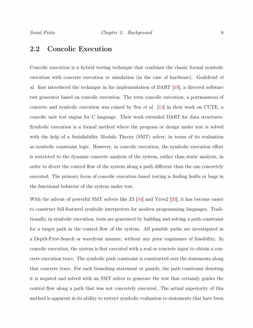
2.2 Concolic Execution
Concolic execution is a hybrid testing technique that combines the classic formal symbolic
execution with concrete execution or simulation (in the case of hardware). Godefroid et
al. first introduced the technique in his implementation of DART [19], a directed software
test generator based on concolic execution. The term concolic execution, a portmanteau of
concrete and symbolic execution was coined by Sen et al. [13] in their work on CUTE, a
concolic unit test engine for C language. Their work extended DART for data structures.
Symbolic execution is a formal method where the program or design under test is solved
with the help of a Satisfiability Modulo Theory (SMT) solver, in terms of its evaluation
as symbolic constraint logic. However, in concolic execution, the symbolic execution effort
is restricted to the dynamic concrete analysis of the system, rather than static analysis, in
order to divert the control flow of the system along a path different than the one concretely
executed. The primary focus of concolic execution based testing is finding faults or bugs in
the functional behavior of the system under test.
With the advent of powerful SMT solvers like Z3 [34] and Yices2 [35], it has become easier
to construct full-featured symbolic interpreters for modern programming languages. Tradi-
tionally, in symbolic execution, tests are generated by building and solving a path constraint
for a target path in the control flow of the system. All possible paths are investigated in
a Depth-First-Search or wavefront manner, without any prior cognizance of feasibility. In
concolic execution, the system is first executed with a real or concrete input to obtain a con-
crete execution trace. The symbolic path constraint is constructed over the statements along
that concrete trace. For each branching statement or guards, the path constraint denoting
it is negated and solved with an SMT solver to generate the test that certainly guides the
control flow along a path that was not concretely executed. The actual superiority of this
method is apparent in its ability to restrict symbolic evaluation to statements that have been
Sonal Pinto Chapter 2. Background 9
influenced by the input, by only using the symbols for primary input. This reduces the over-
all computational effort, as fewer symbolic constraints need to be constructed and smaller
logical constraints need to be solved, for the same goal as traditional symbolic execution.
Nonetheless, concolic execution explores a tree of possible execution paths in a depth-first
search manner, and requires being bounded.
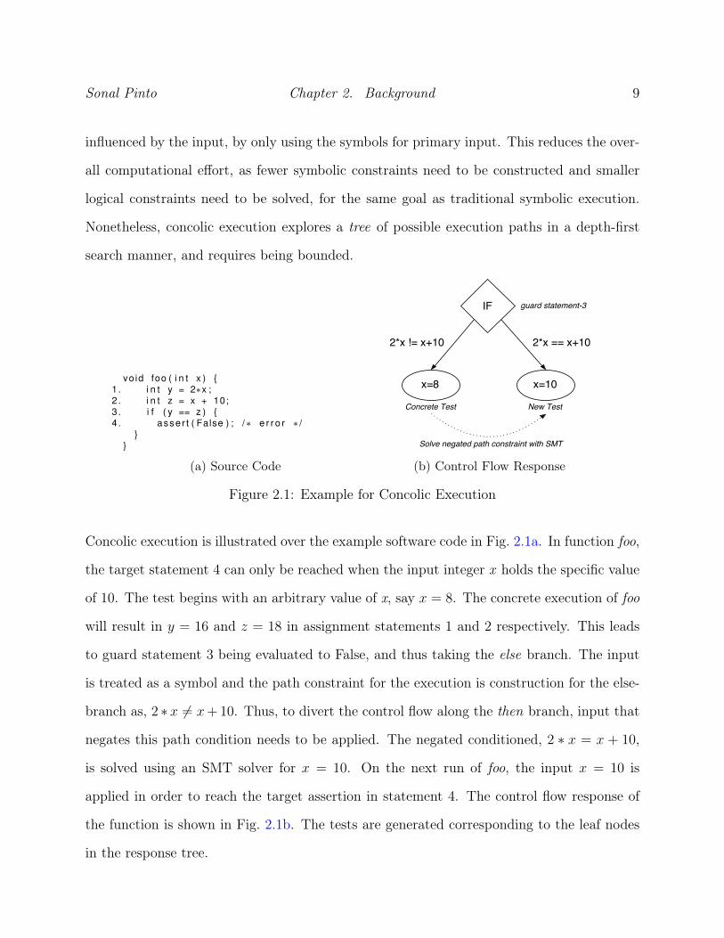
vo id foo ( i n t x ) {1 . i n t y = 2∗x ;2 . i n t z = x + 10;3 . i f ( y == z ) {4 . asser t ( False ) ; /∗ e r r o r ∗ /
}}
(a) Source Code (b) Control Flow Response
Figure 2.1: Example for Concolic Execution
Concolic execution is illustrated over the example software code in Fig. 2.1a. In function foo,
the target statement 4 can only be reached when the input integer x holds the specific value
of 10. The test begins with an arbitrary value of x, say x = 8. The concrete execution of foo
will result in y = 16 and z = 18 in assignment statements 1 and 2 respectively. This leads
to guard statement 3 being evaluated to False, and thus taking the else branch. The input
is treated as a symbol and the path constraint for the execution is construction for the else-
branch as, 2 ∗ x 6= x+10. Thus, to divert the control flow along the then branch, input that
negates this path condition needs to be applied. The negated conditioned, 2 ∗ x = x + 10,
is solved using an SMT solver for x = 10. On the next run of foo, the input x = 10 is
applied in order to reach the target assertion in statement 4. The control flow response of
the function is shown in Fig. 2.1b. The tests are generated corresponding to the leaf nodes
in the response tree.

Sonal Pinto Chapter 2. Background 10
2.3 Scaling through Factored Exploration
A distinct difference between hardware and software with respect to its formal techniques
like Bounded Model Checking (BMC) and Symbolic Execution is in the abstract functional
description of the systems (HDL for hardware, and programming languages for software).
The HDL source of the hardware consists of both concurrent and procedural statements and
code blocks. The hardware is described in terms of its response to primary-input stimuli
and its stored system states in memory elements such as registers and memory arrays. For
sequential hardware, the HDL is usually synchronized to one or more clocks. Per clock cy-
cle, not all system states are reachable regardless of primary input. The entire HDL has
to be unrolled and evaluated per clock cycle. Any practical test for hardware will consist
of a non-negligible number of cycles. It has been previously mentioned in this thesis that
such large unrolling makes symbolic execution unrealistic, even under the assumption that a
full featured symbolic interpreter is present for the HDL design under test. Nonetheless, to
overcome this clear limitation of formal methods under deterministic computing paradigms,
clever techniques like inductive reasoning and variable ordering strategies have been suc-
cessfully implemented. In [18], SAT-based (Boolean Satisfiability) BMC was scaled through
variable ordering that is learned during incremental unrolling, and efficient BMC-specific
ordering tactics implemented were in the core SAT solver. With the help of signal corre-
lations, implications were deduced across multiple cycles of unrolling in [27]. This allowed
their SAT-based BMC to scale phenomenally beyond previous work at that time, as it could
reduce the overall search space.
The primary input is engaged for every cycle in the HDL, and every primary-input signal
requires being cycle-annotated to be evaluated symbolically. The degree of unrolling decides
the complexity of the symbolic execution. Such a formal evaluation of the HDL can be
understood as having static or state variables in software functions that are engaged in an
Sonal Pinto Chapter 2. Background 11
infinite loop [24]. This property is unique to hardware as software testing does not require
unrolling of cycles as in hardware and the concrete path under evaluation begins at distinct
start and end system state. In traditional hardware concolic execution [17], all symbolic
evaluation along a concrete simulation trace begins at predefined state (say, reset) prior to
which no signal has been stimulated by the primary input. At this starting state, all signals
are either assigned initial constant values or some function of the primary input. For each
cycle hence, it is easy to detect signals influenced or stimulated by cycle-annotated primary
input by following the use-definition [26] chain. This is akin to software testing of a function
where no function-scoped variable has a deterministic value before execution. Despite having
the property to control the complexity of symbolic execution by limiting the unrolling, the
effort necessarily begins at a fixed starting state. Thus, a maximum bound for cycles that
can be concolically simulated for test generation from the starting state is unfortunately
conditioned on computational power and time at disposal.
However, with appropriate instrumentation, concolic execution for HDL can begin at any
system state. This is enabled by having access to values of memory elements through sim-
ulator instrumentation. Say, a new exploration needs to begin a system state that is 1000
cycles away from the predefined reset state, then, after simulation of that base test the val-
ues of all memory elements form the initial values for symbolic execution (constrained to
primary input stimulated statements) of the new test. Though this constrains the input
search domain to the cycles of simulation; it allows for path constraints to be constructed in
a search space previously computationally unreachable. The search space can be factored to
computationally feasible exploration sizes (test length) using concolic execution. This allows
for piecewise test generation similar to iterative or generational search-based techniques, a
feature previously not conceived for hardware constraint-based techniques. In software con-
colic execution, without heavy instrumentation, a large functional (say, 1000-line) concrete
Sonal Pinto Chapter 2. Background 12
path cannot be split into parts and individually symbolically analyzed. In hardware, we can
split a long test (say, 1000 cycles) into incremental parts, reading the system state before
and after each part.
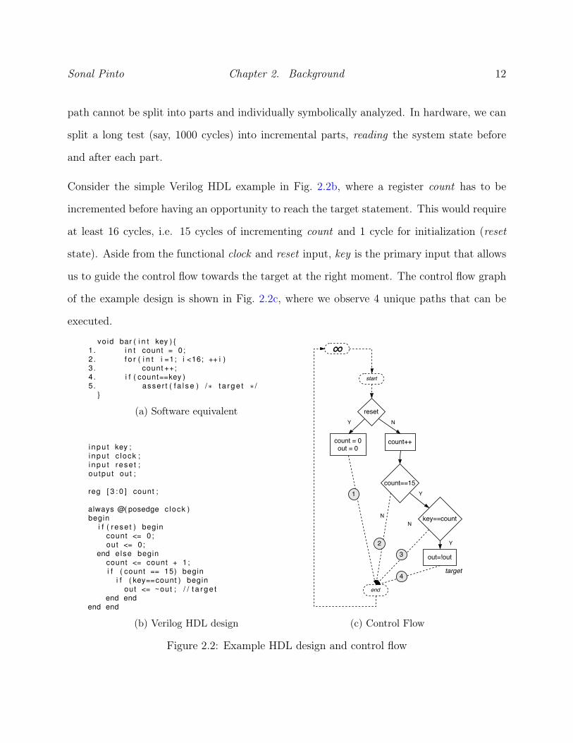
Consider the simple Verilog HDL example in Fig. 2.2b, where a register count has to be
incremented before having an opportunity to reach the target statement. This would require
at least 16 cycles, i.e. 15 cycles of incrementing count and 1 cycle for initialization (reset
state). Aside from the functional clock and reset input, key is the primary input that allows
us to guide the control flow towards the target at the right moment. The control flow graph
of the example design is shown in Fig. 2.2c, where we observe 4 unique paths that can be
executed.
vo id bar ( i n t key ) {1 . i n t count = 0 ;2 . f o r ( i n t i =1; i <16; ++ i )3 . count ++;4 . i f ( count==key )5 . asser t ( f a l s e ) /∗ t a r g e t ∗ /
}
(a) Software equivalent
i npu t key ;i npu t c lock ;i npu t rese t ;ou tput out ;
reg [ 3 : 0 ] count ;
always @( posedge c lock )begin
i f ( rese t ) begincount <= 0;out <= 0;
end else begincount <= count + 1 ;i f ( count == 15) begin
i f ( key==count ) beginout <= ~out ; / / t a r g e t
end endend end
(b) Verilog HDL design (c) Control Flow
Figure 2.2: Example HDL design and control flow

Sonal Pinto Chapter 2. Background 13
In the first necessary reset cycle, path-1 is taken. Pursuant of bounded concolic execution
(with concrete stimuli of k = 0), we would have to begin analysis at this state which pro-
vides constant initial values for variables participating in the execution. For the next 15
cycles, path-2 is executed, and the path-constraint grows accordingly. In the 16th cycle, the
concrete input key = 0 leads the execution away from the target, along path-3. Overall,
the relevant symbolic path constraint for these 16 cycles is described in Fig. 2.3a. The large
path constraint associated with the target requires the incremental symbolic computation
of count (assuming for the sake of the example that no advanced symbolic execution op-
timization techniques are being used). Without knowledge of initial values of count this
evaluation would not be possible. This situation where the evaluation is forced to begin
at predetermined start state is akin to the Input-Output testing of functions in Software
Testing [26], where all variables are scoped within the function and evaluation begins at the
start of the function block. The evaluation cannot begin at a point within that function,
as we would not know the values of variables altered before that point (without extensive
instrumentation to access the concrete environment). Looking at the software equivalent in
Fig 2.2a, we see that the formal analysis cannot simply begin at statement-4. The value of
count needs to be symbolically determined over the statements 2-3 from its initial definition
in statement-1.
i n i t : r ese t s t a t ecount=0out=0
Concrete Test : key1−16=0 , 16 cyc lespath c o n s t r a i n t :
count=count+1count=count+1. . . 15 times total!count=count+1count=count+1<not ( key16==count ) >
(a) 16-cycle path constraint
base t e s t : key1−12=0 , 12 cyc lesi n i t : Concrete System State Read
count=12out=0
Concrete Test : key13−16=0 , 4 cyc lespath c o n s t r a i n t :
count=count+1count=count+1count=count+1<not ( ( key16==count ) >
(b) Path constraint for segment-4
Figure 2.3: Complexity of symbolic analysis

Sonal Pinto Chapter 2. Background 14
Assume that instrumentation to access any signal in the simulated design is available. Being
able to concretely read the system state at any cycle would not only allow the test to be at a
state away from the reset state, but also enable the ability to factor the test. Let us assume
that the 16-cycle test is factored into four parts, each of length 4 with the same concrete
stimuli of key = 0 throughout. Consider the first segment (cycles 1-4) which concretely
simulates the first four cycles of the same execution as in Fig. 2.3a. However, no path
constraint would need to be built in this factored segment as no statement was influenced
by input (implying that control flow in the segment cannot be changed as no stimulus is
consumed). The test so far forms the base test for the next segment, i.e. the concrete
stimuli of segment-1 is applied before concolic execution of segment-2. Once, the base test
is simulated, the system state is concretely read to determine the initial values for concolic
execution in the current segment.
The case for the segment-2 (cycles 5-8) and segment-3 (cycles 9-12) would be the same as
segment-1, as the system continues to execute through path-2. For the fourth segment (cycles
13-16), the first three segments form a cumulative base test of 12 cycles which would lead
to the system state consisting of count = 12 and out = 0. This system state is read from
memory elements (registers and arrays) and provide initial values for the formal analysis
distant from the reset state. The concrete stimuli for segment-4 are four cycles of key = 0
leading to a concrete trace that goes through path-3 in cycle-16. The path constraint for
this factored segment is shown in Fig. 2.3b. The size and computational complexity of this
4-cycle path constraint are smaller than the 16-cycle path constraint. The cyclic execution
of hardware forms a natural boundary for factoring and analysis where the system state can
be read between cycles (or segments of cycles).
While it true that a larger path constraint has a greater visibility of the effect of primary
input on the control flow, it is also expensive. Factoring the exploration into smaller tests
Sonal Pinto Chapter 2. Background 15
and obtaining the initial values of signals through instrumentation, each time bringing the
system away from the initial state, is the compromise we adopt to scale our concolic execution
methodology.
2.4 Verilator and RTL Instrumentation
Verilator [36] is an open source transpiler (source-to-source compiler) that converters Ver-
ilog HDL into a high-performance C++ behavioral simulator. Given synthesizable Verilog,
Verilator outputs a C++ class representing a cycle-accurate functional model of the RTL.
All signals (IO and internal) of the top hierarchical component of the design are directly ac-
cessible as public data members of this class. The class also provides a public function, eval,
which simulates the model’s behavioral response based on the current values of its public
data members.
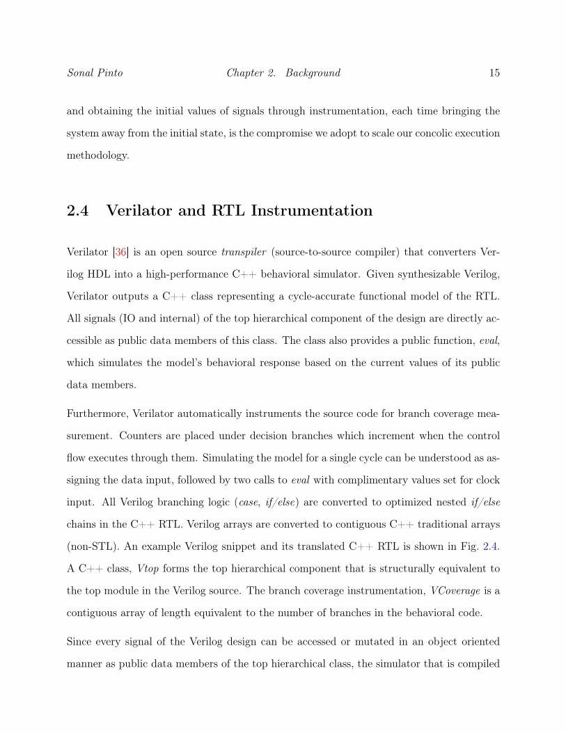
Furthermore, Verilator automatically instruments the source code for branch coverage mea-
surement. Counters are placed under decision branches which increment when the control
flow executes through them. Simulating the model for a single cycle can be understood as as-
signing the data input, followed by two calls to eval with complimentary values set for clock
input. All Verilog branching logic (case, if/else) are converted to optimized nested if/else
chains in the C++ RTL. Verilog arrays are converted to contiguous C++ traditional arrays
(non-STL). An example Verilog snippet and its translated C++ RTL is shown in Fig. 2.4.
A C++ class, Vtop forms the top hierarchical component that is structurally equivalent to
the top module in the Verilog source. The branch coverage instrumentation, VCoverage is a
contiguous array of length equivalent to the number of branches in the behavioral code.
Since every signal of the Verilog design can be accessed or mutated in an object oriented
manner as public data members of the top hierarchical class, the simulator that is compiled

Sonal Pinto Chapter 2. Background 16
always @( posedge c lock ) begini f ( rese t ) begin / / 1 7
s ta te1 <= 0;end else begin / / 2 6
case ( s ta te1 )0 : / / 1 9
i f ( count1 == 4 ’ h f ) / / 1 8s ta te1 <= 1;
1 : / / 2 1i f ( count2 == 4 ’ h f ) / / 2 0
s ta te1 <= 2;2 : / / 2 3
i f ( count3 == 4 ’ h f ) / / 2 2s ta te1 <= 3;
3 : / / 2 4s ta te1 <= 0;
d e f a u l t : / / 2 5s ta te1 <= s ta te1 ;
endcaseend
end
(a) Verilog HDL
i f ( rese t ) {++(__Vcoverage [ 1 7 ] ) ;s ta te1 = 0U;
} e lse {i f (0U == s ta te1 ) {
++(__Vcoverage [ 1 9 ] ) ;i f (0 xfU == count1 ) {
++(__Vcoverage [ 1 8 ] ) ;s ta te1 = 1U;
}} e lse {
i f (1U == s ta te1 ) {++(__Vcoverage [ 2 1 ] ) ;i f (0 xfU == count2 ) ) {
++(__Vcoverage [ 2 0 ] ) ;s ta te1 = 2U;
}} e lse {
i f (2U == s ta te1 ) {++(__Vcoverage [ 2 3 ] ) ;i f (0 xfU == count3 ) {
++(__Vcoverage [ 2 2 ] ) ;s ta te1 = 3U;
}} e lse {
i f (3U == s ta te1 ) {++(__Vcoverage [ 2 4 ] ) ;s ta te1 = 0U;
} e lse {s ta te1 = s ta te1 ;++(__Vcoverage [ 2 5 ] ) ;
}}
}++(__Vcoverage [ 2 6 ] ) ;
}}
(b) Verilated C++ RTL
Figure 2.4: Verilog code snippet and its Verilator translated C++ RTL
using the Verilated model (C++ RTL) is explicitly well suited for concolic execution. While
building path constraints, used signals that have not been stimulated by primary input
can simply be read from the simulator instance and substituted as concrete values. In the
traditional symbolic evaluation, the value for unstimulated variables would be evaluated from
its last definition.

Sonal Pinto Chapter 2. Background 17
2.5 Related Work
HYBRO [17] demonstrates viable RTL directed test generation by symbolically executing the
concrete trace extracted from the design Control Flow Graph (CFG) [9] during simulation.
The RTL is instrumented with branch coverage counters, and the execution path in the CFG
is deduced by observing the change in branch counters per simulation cycle. From a fixed
starting state, the design is concretely simulated using random vectors. The entire extracted
concrete trace is then symbolically evaluated to reveal activated (stimulated by input) guards
along that trace. In HYBRO, both cycle-annotated primary input and unstimulated internal
signals are considered for the symbolic execution effort. The path constraints for activated
guards are negated (mutated) and solved using an SMT solver, in the reversed order of their
concrete execution. The solution (in terms of primary input) that satisfies the negated path
expressions for the guards is used to form the new test that offers an exploration of a new
region in the test. HYBRO improves upon STAR [16] where previously mutated guards
would have been retained, resulting in repeated execution of previously explored paths. As
a compromise, in subsequent iterations, mutation is not attempted on guards that lead to
branches that have been explored within the bounded region. Thus, HYBRO poorly relies
on the random concrete stimuli to reach system states that require repeated execution of
certain paths (e.g. loops and counters). Moreover, HYBRO does not support HDL array
elements or memories which are integral parts of practical designs.
Xiaoke and Mishra [25] also interleaved concrete simulation and symbolic execution, by
instrumenting the RTL with statements that printed the concrete execution in terms of
syntactic elements. The design is simulated with random stimuli and a trace file representing
the concrete execution is output. The resultant trace file is symbolically analyzed to reveal
activated statements. In contrast to HYBRO, which symbolically evaluates unstimulated
variables used in activated statements, their work could simply substitute them with their

Sonal Pinto Chapter 2. Background 18
concrete equivalent (parsed from the print statements in the trace file). [25] also supports
symbolic evaluation of memory arrays by treating them as individual index-annotated scalar
variables. In a statement where an array variable is used, the index is evaluated as concrete,
and the appropriate symbol for the memory index is substituted. Both [17] and [25] generate
tests by unrolling the design for a fixed number of cycles from a specific starting state and
are limited to the exploration of system states reachable within the unrolled cycles.
PACOST [32, 33], a target oriented RTL test generator has shown success in reaching deep
hard-to-reach states by using factored explorations adjunct to interleaved concrete and sym-
bolic simulation. Both the single-cycle and the multi-cycle path constraint variant of PA-
COST relies on systematically building the test over smaller explorations. In an exploration,
the state space is explored in a similar manner to [17], where the guards are mutated in the
symbolic path-constraint constructed over the concrete execution. Successive explorations
begin at a heuristically determined starting state discovered in the current exploration. A
selection of a starting state is determined from state distances derived from an abstract
model of the RTL [29]. However, the construction of path constraints in each exploration is
limited to variables that can trace their use-definition chain to an input variable within that
exploration. If any variable in a guard path expression cannot be defined solely in terms of
primary input, then no mutation effort is performed on that guard. In contrast to PACOST,
our factored explorations are guided by heuristic metrics derived from the overall coverage
status of the test, and our analysis is not restricted to use-definition chains wholly contained
within the exploration. Furthermore, in PACOST, abstraction of the RTL leads to loss of
information and the calculation of abstract state distances is limited by their BMC-based
preprocessing.
Guiding the direction of test generation by dynamically calculating branch coverage based
heuristics is described in BEACON [20]. It is a search-based testing technique which uses a

Sonal Pinto Chapter 2. Background 19
hybrid Ant Colony Optimization and evolutionary algorithm to maximize branch coverage in
the RTL design under test. The Verilog RTL source is translated to a functional C++ model
and is instrumented for branch coverage measurement. The underlying search heuristics are
updated at each iteration during simulation. BEACON is able to reach hard-to-reach states
in a runtime that is orders of magnitude shorter than HYBRO. This is expected as it does
not incur the cost of expensive SMT solver operations. To further improve its performance,
in [15], BEACON was extended with a feature to periodically perform a local state space
search using an SMT-based Bounded Model Checker. This allows the search-based algorithm
to detect branches that could not have been found by a stochastic search alone.

Chapter 3
Cycle-by-Cycle Concolic Execution of
RTL
In this chapter, we introduce a novel concolic execution methodology geared towards rapidly
generating tests at the Register Transfer Level (RTL). The goal of this methodology is to
generate a multi-cycle sequential test that maximizes branch coverage, in the shortest amount
of time. The following is a brief overview of our hybrid concrete and symbolic simulation
test generation method. The overall test is iteratively built over several explorations using
randomly generated concrete input vectors (concrete stimuli), from a predetermined starting
system state (say, system reset), bounded to a fixed number of simulation cycles. For
each exploration, we perform cycle-by-cycle concolic simulation where symbolic expressions
are only constructed for primary input stimulated (activated) statements in the concrete
execution trace. Not all statements or variables are data-dependent on primary input. Such
statements can be abstracted away, and the unstimulated variables defined by them can be
substituted for their concrete values (read from the simulator) if they are eventually used in
other activated statements. As a result, the overall symbolic evaluation effort is significantly
20

Sonal Pinto Chapter 3. Cycle-by-Cycle Concolic Execution of RTL 21
reduced.
The objective of concolic simulation is to dynamically reveal activated control points (guard
statements) in the trace. The symbolic expressions for activated guards aremutated (negated)
using a formal Satisfiability Modulo Theory (SMT) solver, to generate mutation stimuli. Al-
tering the concrete test with the specific mutation stimuli generates the test that reaches
branches that were not executed during the current exploration. For the purpose of experi-
mentation, a bounded test generator based on this concolic execution methodology is built.
In each exploration, the test for each discovered branch is recorded. The overall test is the
optimal concatenation of tests selected from pool of all tests recorded so far, such that all
discovered branches are covered.
The cycle-by-cycle concolic execution methodology proposed in this thesis offers a significant
reduction in functional test generation time compared to previous work [17, 25] based on
similar hybrid concrete and symbolic evaluation.
The rest of the chapter is organized as follows. Terminology for key components of our
concolic execution algorithm is described in Section 3.1. In Section 3.2 details the prepro-
cessing and instrumentation of our RTL simulation framework. Our cycle-by-cycle concolic
execution methodology is described in great detail over an example in Section 3.3. Lastly,
our method is tested against previous work in Section 3.4.
3.1 Terminology
A concrete path or trace is defined as a sequence of statements (assignments and guards)
executed upon simulating the RTL source code (for one or more cycles) with concrete in-
put stimuli. However, unlike previous work, we do not construct a path constraint which

Sonal Pinto Chapter 3. Cycle-by-Cycle Concolic Execution of RTL 22
represents concrete trace as the stack of symbolic assignments and guards. Rather, we per-
form cycle-by-cycle concolic evaluation and maintain an Activation Table which stores the
symbolic definition of activated variables defined in assignment statements. In our work,
concolic execution requires symbolically executing the concrete path by only using symbols
for inputs. In each cycle, a symbolic expression is constructed for a statement if it is found
to be activated, with appropriate substitutions for each variable used. For primary inputs,
the cycle annotated input symbol representing them are used. An activated variable is sub-
stituted for its defining symbolic expression fetched from the Activation Table. Values of
unstimulated variables are said to be concrete, and are obtained (read) from the simulator
during simulation (between cycles).
Along a concrete trace, guards that use activated variables or primary inputs are termed
activated guards. For each activated guard, a boolean symbolic expression representing its
predicate and the concrete branch taken is constructed. A guard expression is a function of
input stimuli. To divert the control flow, we attempt to mutate the activated guards. An
activated guard that can be mutated is called a mutable guard and the stimuli that satisfy the
mutation is referred to as the mutation stimuli. The constraint stack for each activated guard
includes its negated expression and the concrete expressions for the intersecting mutable
guards found before it, in this trace. The intersection of guards is defined as having cycle-
annotated input stimuli in common, and we consider this during the mutation effort to
ensure that the mutation stimuli of a latter guard do not mutate the concrete execution of
a former. The constraint stack is solved using an SMT solver. If the constraint stack could
not be solved, then the activated guard is ignored henceforth in the analysis of this trace.
Comparable to [25], our work can build symbolic expressions for statements involving array
accesses (e.g. memory, queues, FIFO) where every element in the array is treated as a
scalar variable annotated by its index. This means that the array index would be read as

Sonal Pinto Chapter 3. Cycle-by-Cycle Concolic Execution of RTL 23
concrete. Thus, upon encountering activated variables being used as array access indexes,
we deactivate them and consider their input stimuli to be immutable stimuli. No symbols
are created for immutable stimuli, and their concrete values are substituted wherever they
are used. In a similar note, our concolic execution methodology considers clocking and reset
inputs as immutable stimuli, and always treats them as concrete values.
3.2 Preprocessing and Instrumentation
This section describes the preprocessing tasks that occur before the real test generation
effort. The RTL is instrumented for both branch coverage and trace recording, the latter
being an enhancement to Verilator introduced as a part of our work.
3.2.1 Concrete Trace Recording
Recording the concrete trace traversed in the design in each cycle is a fundamental operation
in our work. To this end, Verilator [36] (introduced in Section 2.4) compiler source code is
modified to allow for instrumentation of concrete trace recording during functional simula-
tion. The top hierarchal class which simulates the design, Vtop is extended with a C++
integer vector named trace. In the eval function, each branch coverage increment statement
is followed by a command to concatenate the branch ID into the trace (Fig. 3.1). The trace
data structure is cleared before a cycle and read at the end of a cycle. During a call to
eval function, when the execution flows through a path, it is recorded in the trace as unique
sequence of branches. The accumulated sequence of integer branch IDs denotes the concrete
trace and is accessed as a public data member of the top simulator class.

Sonal Pinto Chapter 3. Cycle-by-Cycle Concolic Execution of RTL 24
i f (0U == s ta te1 ) {++(__Vcoverage [ 1 9 ] ) ;t race . push_back ( 1 9 ) ;i f (0 xfU == count1 ) {
++(__Vcoverage [ 1 8 ] ) ;t race . push_back ( 1 8 ) ;s ta te1 = 1U;
}}
Figure 3.1: Instrumentation of concrete trace recording in the eval function of the C++RTL
3.2.2 RTL Translation and Analysis
The task of preprocessing begins with the translation of the Verilog source of the design
into C++ using Verilator. Branch coverage measurement (in-built Verilator feature) and
execution trace recording are instrumented during the translation. The coverage status for
the simulation is the value in each instrumented branch coverage counter. The Verilog
source for the design used as the motivating example in the following section is presented in
Fig. 3.2a. The instrumented C++ code (with simplified variable names for the purpose of
illustration) representing its cycle-accurate behavior is displayed in Fig. 3.2b.
The Abstract Syntax Tree (AST) for the model’s eval (behavioral model) function is parsed
from the Verilated design source code and is transformed into a Control Flow Graph (CFG)
[9]. The AST structure for each statement helps with analysis and construction of symbolic
expressions. A single-cycle execution trace of branch IDs corresponds to a unique path in
the CFG describing both the assignment statements and the concrete execution of guard
statements. In the RTL, by construct, certain branches might be unreachable, i.e. there
exists no test that can guide the control flow through that segment of the code. Verilog
default segments in case statements are the usual examples for these cases. Identification
of such branches helps narrow down the goal space (branch coverage). In this work, we use
signal domain analysis as introduced in [28] across the AST to identify predicates (branch
conditions) that cannot be satisfied under any assignment of the predicate variables. How-

Sonal Pinto Chapter 3. Cycle-by-Cycle Concolic Execution of RTL 25
module DUT( din , c lock , reset , dout ) ;i npu t c lock , rese t ;i npu t [ 7 : 0 ] d in ;output dout ;reg [ 7 : 0 ] b u f f e r [ 0 : 3 ] ;reg [ 1 5 : 0 ] r0 ;reg [ 1 : 0 ] addr ;reg [ 1 : 0 ] s t a t e ;
always @( posedge c lock ) begini f ( rese t ) begin
addr<=0;s ta t e <=0;dout<=0;
endelse begin
case ( s ta te )0 : begin
b u f f e r [ addr ] <=d in ;addr<=addr +1; s ta t e <=1;
end1: begin
b u f f e r [ addr ] <=d in ;addr<=addr +1; s ta t e <=2;
end2: begin
r0<= { b u f f e r [ addr - 1 ] ,b u f f e r [ addr - 2 ] } ;
addr<=0; s ta t e <=3;end3: begin
i f ( r0 == 16 ’hDEAD)dout<=1;
e lsedout<=0;
s ta t e <=0;endendcase end end
endmodule
(a) Verilog RTL
1. i f ( rese t ) {2 . ++coverage [ 0 ] ;
t race . push_back ( 0 )3 . addr =0;4 . s t a te =0;5 . dout =0;
} e lse {6 . ++coverage [ 7 ] ;
t race . push_back ( 7 )7 . i f (0== s ta te ) {8 . ++coverage [ 1 ] ;
t race . push_back ( 1 )9 . b u f f e r [ addr ]= d in ;10. s t a t e =1;11. addr =(3 & (1 + addr ) ) ;
} e lse {12. i f (1== s ta te ) {13. ++coverage [ 2 ] ;
t race . push_back ( 2 )14. b u f f e r [ addr ]= d in ;15. s t a t e =2;16. addr =(3 & (1 + addr ) ) ;
} e lse {17. i f ( (2==( s ta te ) ) ) {18. ++coverage [ 3 ] ;
t race . push_back ( 3 )19. r0 = ( ( b u f f e r [3 & ( addr - 1)] < <8U)
| ( b u f f e r [3 & ( addr - 2 ) ] ) ) ;20. s t a t e =3;21. addr =0;
} e lse {22. i f (3== s ta te ) {23. ++coverage [ 6 ] ;
t race . push_back ( 6 )24. i f (0xdeadU==r0 ) {25. ++coverage [ 4 ] ;
t race . push_back ( 4 )26. dout =1;
} e lse {27. ++coverage [ 5 ] ;
t race . push_back ( 5 )28. dout =0;
}29. s t a t e = 0 ; } } } } }
(b) Instrumented C++ RTL
Figure 3.2: Example Design-Under-Test
ever, we use a non-formal approach [31] by restricting the signal domain range to predicate
control signals that are only assigned constant values across all statements that define them.
In simple terms, given that a predicate variable can take a value from a finite set of values
(parsed from the AST), satisfiability is checked in predicates that use that signal. Branch
expressions which cannot be satisfied are said to be unreachable branches.

Sonal Pinto Chapter 3. Cycle-by-Cycle Concolic Execution of RTL 26
Lastly, a simple harness that instantiates the C++ model and provides generic accessor
functions to its public members (signal variables, coverage counters, trace, and eval) is
generated. The harness is compiled along with the model to obtain the design simulator.
The CFG for the example design is shown in Fig. 3.3a. The AST forming statement-19 is
portrayed in Fig. 3.3b, highlighting a complex expression that utilizes arrays.
(a) Control Flow Graph (b) AST for statement-19
Figure 3.3: Preprocessed CFG and AST
Sonal Pinto Chapter 3. Cycle-by-Cycle Concolic Execution of RTL 27
3.3 RTL Concolic Execution
In this section, our concolic execution methodology is illustrated over the example design
in Fig. 3.2. The following subsections demonstrate a concolic exploration of the design
and the cycle-by-cycle simulation and analysis is annotated in Table 3.1. For this example
exploration, assume a random concrete input of five cycles (cycles 1-to-5 in column 2).
Before simulating the model with the concrete input, user-provided initialization vectors are
applied to the model. In this case, that would be a single cycle of primary input reset set
to high, during cycle-0, beyond which it is held low. This brings the system to the required
starting state. No analysis is performed over the initialization cycles.
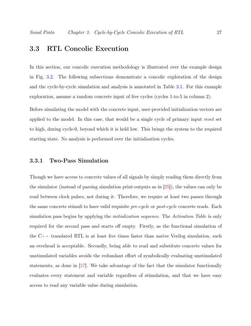
3.3.1 Two-Pass Simulation
Though we have access to concrete values of all signals by simply reading them directly from
the simulator (instead of parsing simulation print-outputs as in [25]), the values can only be
read between clock pulses, not during it. Therefore, we require at least two passes through
the same concrete stimuli to have valid requisite pre-cycle or post-cycle concrete reads. Each
simulation pass begins by applying the initialization sequence. The Activation Table is only
required for the second pass and starts off empty. Firstly, as the functional simulation of
the C++ translated RTL is at least five times faster than native Verilog simulation, such
an overhead is acceptable. Secondly, being able to read and substitute concrete values for
unstimulated variables avoids the redundant effort of symbolically evaluating unstimulated
statements, as done in [17]. We take advantage of the fact that the simulator functionally
evaluates every statement and variable regardless of stimulation, and that we have easy
access to read any variable value during simulation.

Sonal Pinto Chapter 3. Cycle-by-Cycle Concolic Execution of RTL 28
• Pass-1: Concrete Trace Analysis. The design is simulated over the concrete stim-
uli. The concrete execution trace (column 3) traversed in the model is inferred from
the CFG by observing the trace recorded after the cycle. Say, in cycle-1, by noting a
trace of <1, 7>, we can deduce that the execution followed a concrete path of <1F-6-
7T-8-9-10-11> where the guards in statements 1 and 7 evaluated to False (else) and
True (then) respectively. By analyzing the statements along the per-cycle trace, we
mark each used variable as a post-cycle or pre-cycle read, for their particular cycle. A
used variable in marked as a post-cycle-read if the variable was first defined (Verilog
blocking assignment) and then utilized in the same cycle. Else, it is characterized as
a pre-cycle-read. Symbolic analysis of the concrete trace is performed in the second
pass.
• Pass-2: Concolic Execution. In this pass, before simulating a clock pulse with con-
crete stimuli, we first analyze the previously extracted concrete path for the upcoming
cycle, to reveal activated statements (stimulated by primary input or an activated vari-
able from the Activation Table). The used variables in each activated statement which
were marked as pre-cycle-read for this cycle, are now read from the simulator. Next,
the clock pulse is applied. Symbolic expressions (column 5) are constructed for acti-
vated statements using its AST representation with appropriate value substitutions for
the used variables. Post-cycle concrete reads for unstimulated variables are read from
the simulator on demand. The defined activated variable is enlisted in the Activation
Table (column 6). The concrete reads in each cycle are shown in column 4.

Sonal Pinto Chapter 3. Cycle-by-Cycle Concolic Execution of RTL 29
Table 3.1: Discovery of Activated Guards using Concolic Execution
Cycle Concrete Concrete Concrete Statement ActivationStimuli Trace Reads Expressions Table
0 reset=1 – – – –
1 din=68 1F-6-7T-8-9-10-11 addr=0 9: buffer [0 ] = din1
buffer_0 : din1
2 din=178 1F-6-7F-12T-13-14-15-16 addr=1 14: buffer [1 ] = din2
buffer_0 : din1
buffer_1 : din2
3 din=751F-6-7F-12F-
17T-18-19-20-21
addr=219:
r0 = (buffer [1 ] « 8) | buffer [0 ]= (din2 « 8) | din1
buffer_0 : din1
buffer_1 : din2
r0 : (din2 « 8) | din1
4 din=2321F-6-7F-12F-
17F-22T-23-24F-27-
28-29
–Activated Guard 24F:
not(57005 == r0) 7→¬(57005 ==(din2 « 8) | din1)
buffer_0 : din1
buffer_1 : din2
r0 : (din2 « 8) | din1
5 din=22 1F-6-7F-8-9-10-11 addr=0 9: buffer [0 ] = din5
buffer_0 : din5
buffer_1 : din2
r0 : (din2 « 8) | din1
3.3.2 Dynamic discovery and mutation of Activated Guards
For this example, din i denotes the byte input din on cycle i. In cycle-1, the first cycle of
analysis, the assignment statement-9 is found to be activated by the input din. It is seen
that this statement involves the definition of an index in the array buffer. We require that
the array access index variables themselves are concrete. Thus, the concrete value for addr
is pre-cycle-read from the simulator and the index is calculated by substituting it in the AST
for array index selection (ArraySel AST node). To construct the symbolic expression, the
AST is traversed in a depth-first search manner, recursively building expression components.
In the LHS of the activated statement, we use din1 for the construction of the symbolic
expression defining buffer[0]. Finally, we add the index annotated array variable, buffer_0
and its symbolic expression: din1, to the Activation Table. Similarly, in cycle-2, statement-

Sonal Pinto Chapter 3. Cycle-by-Cycle Concolic Execution of RTL 30
14 is found to be stimulated, and the Activation Table is updated with buffer_1 with its
expression: din2.
During cycle-3, statement-19 is found to be activated as it uses activated variables buffer_0
and buffer_1. The symbolic expression for r0 is constructed by substituting values for
activated variables from the Activation Table in statement’s AST representation, as shown
in Fig. 3.4. In cycle-4, statement-24 is the first activated guard to be encountered along
the overall concrete path. We see that, with the concrete stimuli, the execution takes the
else branch, and thus, the appropriate predicate expression is constructed. Statement-9 is
re-activated in cycle-5 and updated in the Activation Table but is not used further in this
exploration. While not shown in the example, it must be noted that if an entry in the
Activation Table is found to be deactivated (defined wholly by unstimulated variables or
constants) while analyzing the concrete path, it is simply removed.
Figure 3.4: Concrete evaluation of array index for symbolic expression construction
Once all the activated guards are discovered, an attempt is made to check if they are
mutable. The negated expression for each activated guard is fed to the SMT solver con-

Sonal Pinto Chapter 3. Cycle-by-Cycle Concolic Execution of RTL 31
strained by expressions for mutable guards with which its stimuli intersects. In the current
example, the expression representing activated guard-24 on cycle-4, is negated to obtain
(57005 ==(din2 « 8) | din1). The solver returns din1 = 173 and din2 = 222 as mutation
stimuli, and guard-24 is found to be a mutable guard in cycle-4.
3.3.3 Iterative Bounded Explorations
The test that reaches branch-4 is built by overwriting the current concrete test with the
mutation stimuli. The new test is simulated to verify that the control flow reaches the target
branch, and recorded as the test for that branch. For the purpose of experimentation and
evaluation of our concolic execution methodology against previous work [17, 25], a simplistic
bounded test generator is built. The strategy followed is similar to HYBRO [17] where
the process of concolic execution is performed over several iterations using random concrete
stimuli, and for each mutable guard discovered, a new test is recorded and added to the pool.
Such iterative explorations begin a the reset state (application of initialization vectors) and
are bounded by a predefined number of simulation cycles, defining the exploration length. In-
creasing the exploration length leads to increased concolic execution complexity as described
in Section 2.3. The final optimal test is greedily derived (maximize branches covered per
test) from the pool of individual tests such that all discovered branches are covered.
3.4 Experimentation and Results
This section evaluates the performance of our cycle-by-cycle concolic execution methodology
against previous work [17, 25] that used hybrid concrete and symbolic execution.

Sonal Pinto Chapter 3. Cycle-by-Cycle Concolic Execution of RTL 32
3.4.1 Experiment Setup
The test generation framework is written in Python (v3.4.3) and uses the Microsoft’s Z3
(v4.5.1) [34] SMT solver. The design information parsed during preprocessing is stored and
accessed as Python objects (Python pickling). The Verilated C++ RTL and the simulator
harness which instantiates and provides accessor functions to the behavioral model of the
design is compiled as shared library object that can be imported as a Python module. All
experiments are run on a Linux (Lubuntu 15.10) machine with an Intel Core i7-975 (3.33GHz)
with 6GB memory.
Table 3.2: Benchmark Description
Benchmark #PI #PO #branches #gates Unreach.b01 4 2 26 45 0b06 2 6 24 66 1b10 11 6 32 172 1b11 7 6 33 366 1b14 32 54 211 3461 12
HYBRO [17] and [25] are bounded test generators that begin at the reset state, and perform
repeated concolic execution for a specific number of cycles. This limits the unrolling of the
RTL and is a parameter to control the computation complexity of the symbolic evaluation
effort. Since, we compare our work against these methods in this chapter, our test generation
framework is built to perform bounded concolic execution. Our work is tested over the same
benchmarks (Table 3.2) from ITC99 as used in [17]. Column 6 (Unreach.) in this table shows
the number of branches that are found to be guaranteed unreachable during preprocessing.
The cost of preprocessing which includes translation, parsing, static analysis and simulator
compilation is at worst under 2s.

Sonal Pinto Chapter 3. Cycle-by-Cycle Concolic Execution of RTL 33
3.4.2 Branch Coverage
Table 3.3 highlights the performance of our concolic execution methodology over HYBRO [17]
and [25] in terms of branch coverage and runtime. Column 3-5 (BC% ) shows the overall
branch coverage which is measured over all branch points. Column 6 (Reach. BC% ) shows
our reachable branch coverage which discounts branches that are deemed guaranteed un-
reachable during preprocessing. Column 2 (Unroll Cycles) shows the degree of unrolling
(same as [17]), and column 7 (Iter.) shows the number of iterations or rounds of concolic
execution engaged. The number of rounds is decided experimentally per bound where it is
initially set at 4, and increased until a high branch coverage (>90%) is consistently obtained.
The column 8 (#vec.) indicates the length of the final test that greedily covers all branches
discovered in the test generation process. Information about test length was not provided in
the compared works.
Table 3.3: Comparison of Branch Coverage
Bench. Unroll Cycles BC1% Reach. BC% Iter. #vec2HYBRO [25] Oursb01 10 94.44 96.3 100 100 4 35b06 10 94.12 96.3 95.83 100 4 39b10 30 96.77 96.67 96.88 100 8 66b11 10 78.26 81.82 93.94 96.875 16 68b11 50 91.3 94.44 93.94 96.875 8 76b14 15 83.5 98.95 92.89 98.49 36 5061 Number of branches present in the RTL may vary between compared methods due to in-strumentation differences.2 Test length not provided in [17] (HYBRO) and [25]
Minor differences in reachable coverage might be attributed to the different instrumentation
methods used in compared works. Therefore, both overall coverage and reachable coverage
from our work are reported. Our work generates tests that can reach more than 95% of all
reachable branches across all compared benchmarks. Our methodology manages to cover all
Sonal Pinto Chapter 3. Cycle-by-Cycle Concolic Execution of RTL 34
reachable branches in the case of b01, b06 and b10. In the design b14, we achieve 92.89%
(98.5% reachable) branch coverage compared to HYBRO with 83.5% overall coverage. The
test for b14 is comparable to the search success of [25] (98.95% reported branch coverage).
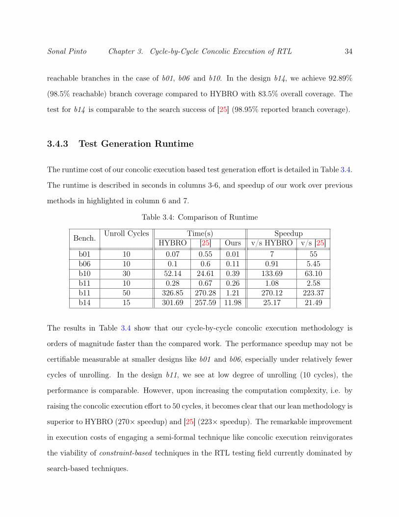
3.4.3 Test Generation Runtime
The runtime cost of our concolic execution based test generation effort is detailed in Table 3.4.
The runtime is described in seconds in columns 3-6, and speedup of our work over previous
methods in highlighted in column 6 and 7.
Table 3.4: Comparison of Runtime
Bench. Unroll Cycles Time(s) SpeedupHYBRO [25] Ours v/s HYBRO v/s [25]
b01 10 0.07 0.55 0.01 7 55b06 10 0.1 0.6 0.11 0.91 5.45b10 30 52.14 24.61 0.39 133.69 63.10b11 10 0.28 0.67 0.26 1.08 2.58b11 50 326.85 270.28 1.21 270.12 223.37b14 15 301.69 257.59 11.98 25.17 21.49
The results in Table 3.4 show that our cycle-by-cycle concolic execution methodology is
orders of magnitude faster than the compared work. The performance speedup may not be
certifiable measurable at smaller designs like b01 and b06, especially under relatively fewer
cycles of unrolling. In the design b11, we see at low degree of unrolling (10 cycles), the
performance is comparable. However, upon increasing the computation complexity, i.e. by
raising the concolic execution effort to 50 cycles, it becomes clear that our lean methodology is
superior to HYBRO (270× speedup) and [25] (223× speedup). The remarkable improvement
in execution costs of engaging a semi-formal technique like concolic execution reinvigorates
the viability of constraint-based techniques in the RTL testing field currently dominated by
search-based techniques.

Chapter 4
Test Generation using Factored
Explorations
Concolic execution on its own is hindered by the same limitations of path explosion and
computational effort of evaluation over a large number of cycles. The entire Control Flow
Graph (CFG) of the design is processed every cycle. As demonstrated in [32], factoring the
exploration into a smaller number of cycles and combining the results of each exploration
offers a promising avenue to scale. In this chapter, we present, CORT (Concolic RTL Test
Generator), a methodology for RTL directed test generation that aims to maximize branch
coverage with a minimal number of test vectors, in the shortest amount of time. Our work
treats the test generation problem as a task of iteratively building the global Test Decision
Tree (TDT) for the design over each exploration.
The following is a short overview of CORT’s underlying test generation methodology. We
iteratively build upon several relatively smaller explorations to generate the overall test. For
each exploration, we perform a cycle-by-cycle concolic simulation to build the tests that
reach branches that were not executed by the current concrete simulation, as described in
35
Sonal Pinto Chapter 4. Test Generation using Factored Explorations 36
Chapter 3. Firstly, the costly construction and solving of symbolic expressions is limited to
primary input stimulated (activated) statements. Secondly, concrete values of unstimulated
signals are substituted in expressions that use them. These measures reduce the cost of
symbolic evaluation effort. In order to reveal alternate execution paths in the concrete
simulation, the negated symbolic expressions for activated guard statements are solved using
a formal Satisfiability Modulo Theory (SMT) solver, to generate mutation stimuli.
The concrete and mutation stimuli are used to build a test decision tree which represents
the control-flow response of the design in the exploration. The decision trees from individual
explorations incrementally uncover the overall control-flow response of the design to various
stimuli over several cycles, i.e., a global Test Decision Tree. This is subsequently used to guide
new explorations along heuristically determined starting system states. Once all explorations
have concluded, the optimal test is derived directly from the global Test Decision Tree.
The rest of the chapter is organized as follows. Section 4.1 introduces the paradigm of the
Test Decision Tree, along with its construction and interpretation. The CORT framework
is described in detail and the example introduced in Chapter 3 is continued in Section 4.2.
Finally, CORT is benchmarked and evaluated against previous work in Section 4.3.
4.1 Test Decision Tree
The test generation effort is represented as a decision tree in our work. Performing concolic
execution over a given sequence of input vectors (concrete stimuli), we detect mutable guards
and their corresponding mutation stimuli. The mutable guards can be considered as points of
divergence in the control-flow, with the divergence being achieved by applying the mutation
stimuli instead of concrete stimuli.

Sonal Pinto Chapter 4. Test Generation using Factored Explorations 37
Structurally, the decision tree consists of two types of nodes, data nodes and control nodes.
A data node comprises zero or more concrete input vectors called default stimuli. Control
nodes are non-terminal, and detail a cycle annotated mutable guard, its concrete execution
(default execution) and mutation stimuli.
An exploration is the task of performing concolic execution over a given concrete stimuli
and returning a decision tree representing its control-flow response. The exercise of building
a decision tree begins with an empty data node. The concrete input vectors are enlisted
cycle-by-cycle as default stimuli until their execution discovers a mutable guard. Thus, the
data node leads to a new control node which will branch into two children, along edges called
default and mutate, indicating the concrete and divergent execution of the mutable guard,
respectively. The control node holds the mutation stimuli, and its branches represent a choice
to either default or mutate (application of mutation stimuli) the control-flow. Subsequent
concrete input vectors are enlisted into the default data nodes, branching as necessary until
all concrete stimuli are exhausted.
Construction of the test represented by a data node in the decision tree requires a reverse
traversal from that node towards the root gathering input vectors along the way. The default
stimuli from each traversed data node are first collected in its entirety. Then, the mutation
stimuli are merely noted from the control nodes that fell on the mutate branch of their
parent during traversal. In situations where some mutation stimulus of a deeper control
node coincides (same signal on the same cycle) with the mutation stimulus of a higher
control node, the latter is ignored. Lastly, the default stimuli are overwritten by mutation
stimuli for the cycles that it denotes. The task of overwriting the default stimuli with the
mutation stimuli is indicative of the minimum change in the input vectors necessary to guide
the control-flow to the target node. There is a need to apply the mutation stimuli over the
complete default stimuli because the mutation of a guard (while honoring the control-flow

Sonal Pinto Chapter 4. Test Generation using Factored Explorations 38
through the guards above it) might require altering input, many cycles in the past.
(a) TDT (b) Test to reach node n3
Figure 4.1: Test Decision Tree for the example exploration in Section 3.3
Continuing the example in Section 3.3, the decision tree in Fig. 4.1a shows the response
uncovered by the concolic execution based exploration. The test decision tree can be under-
stood as an abstraction of the CFG unrolled over the simulated cycles, in terms of stimuli
and response. In each cycle, a concrete input vector is applied to the system and a unique
path is traversed in the CFG. However, the response to the stimuli may not be guaranteed in
the same cycle, and in some cycles, there is no controllable response at all (cycle 1-3 in the
example shown in Section 3.3). Thus we store the minimum amount information in terms
of stimuli distributed over data and control nodes, describing the control flow response and
means to alter it (mutation stimuli of control nodes). Data node n0 in the TDT accumulates
the first 4 concrete input vectors as no mutable guard was discovered before that point. In
cycle 4, according to the concrete (default) execution the mutable guard-24 takes the False
path. Control node n1 records this control-flow response and the mutation stimuli that can
alter it. The unexplored part of the control-flow response, n3 appears on the mutate edge
Sonal Pinto Chapter 4. Test Generation using Factored Explorations 39
of n1. The remaining default stimuli is accumulated in data node n2.
If the primary input din is modified as per the mutation stimuli of n1 on cycles 1 and 2 in
the decision tree, then the system would execute the True branch for guard-24 on cycle-4.
This is well represented in the TDT by the test that reaches node n3. From the TDT, we
see that the test for n3 is formed by <n0, n1, n3>. First, the default stimuli from the
data nodes n0 and n3 are collected. Since, n3 is currently empty, only n0 can contribute
its default stimuli. This action reveals the length of the test to be 4 cycle long. Next, the
mutation stimuli from n1 overrides the concrete stimuli on the appropriate cycles. Overall,
a 4 cycle test (Fig. 4.1b) is constructed to reach node n3.
4.2 CORT Framework
The framework for CORT is illustrated in Fig. 4.2. Identification of clocking and reset signals
and initialization input vectors is expected from the user, along with the Verilog Hardware
Description Language (HDL) source for the design. Currently, our work can handle multiple
synchronous clocks, each of which can toggle at different rates. The user also configures a
search strategy (consisting of several options) to be used for test generation.
Before test generation, a preprocessor generates a cycle-accurate functional simulator from
the given Verilog alongside extracting various design information. The Test Generator (TG)
block engages the Concolic Execution Engine (CEE) for several explorations towards the
goal of building a test that achieves maximum branch coverage. The CEE receives input
vectors from the TG and performs concolic execution over their concrete simulation. It
discovers mutable guards and their mutation stimuli, and a returns a decision tree identifying
them. The TG stitches these decision trees from individual explorations to form a global
Test Decision Tree (TDT). At the start of each exploration, the TG selectively determines

Sonal Pinto Chapter 4. Test Generation using Factored Explorations 40
Figure 4.2: CORT Framework
terminal nodes in the TDT to commit new explorations from and generates appropriate input
vectors to reach that node followed by random input vectors for the unexplored cycles. Once
all explorations have completed, the input vectors that form the optimal test are written
out. The working of the CORT framework is described over the example introduced in
Section 3.2.2.

Sonal Pinto Chapter 4. Test Generation using Factored Explorations 41
4.2.1 Preprocessing
The Preprocessor performs the translation and analysis tasks described in Section. 3.2. The
Verilog RTL source is translated to C++ and harnessed to produce a cycle-accurate func-
tional simulator. The Abstract Syntax Tree (AST) and Control Flow Graph (CFG) [9] is
extracted during this phase along with specifications for various signals in the design. To
avoid redundant illustration, the translated C++ RTL for the example design introduced in
Section 3.2.2 and its behavioral CFG is shown in Fig. 3.2b and Fig. 3.3a respectively.
Figure 4.3: Branch Transition Graph
RTL for FSM-based designs often involves guidepost variables to denote the state of the sys-
tem. In CORT, we extend the preprocessing task towards the static analysis of assignments
and guards for such variables in the AST to construct a Branch Transition Graph (BTG)
as described in [31]. A node in the BTG is representative of a state in an FSM graph, and
its branch coverage point identifies the guard that acts as its state-variable guidepost. The
BTG edges denote the branch that must be covered to transition from the current state to
the next. We can associate all branch points with their respective BTG nodes, by following
their hierarchy in the CFG. This task mimics the purpose of design abstraction in [32] and
aims to identify the underlying design FSM. The BTG representation of the FSM in the

Sonal Pinto Chapter 4. Test Generation using Factored Explorations 42
example design is shown in Fig. 4.3.
4.2.2 Concolic Execution Engine
The Concolic Execution Engine (CEE) is the heart of the CORT framework and performs
the primary task of exploring the design response for a given sequence of input vectors. It
follows the same core concolic execution methodology as described in Section 3.3. The Test
Generator (TG) provides the CEE with a sequence of concrete input vectors (column 2 in
Fig. 3.1) to be used for a new exploration along with a base test sequence which brings the
simulated design to a desired state.
Prior to simulation during both phases of our cycle-by-cycle concolic execution, initialization
vectors and the base test are applied to the model. Concolic execution is only performed
on the exploration vectors, and not on the initialization and base test vectors. The CEE
simulates the concrete input and symbolically evaluates the trace to discover mutable guards,
and their mutation stimuli. In our example, that would be guard-24 on cycle-4 with a
mutation stimuli of din1 = 173 and din2 = 222 which allows the test to progress to the True
branch (branch 4). Once the concolic analysis is completed, the CEE constructs a decision
tree (Fig. 4.1a) for the current exploration as per Section 4.1 and returns it to the Test
Generator.
4.2.3 Test Generation
The Test Generator (TG) block is primary controller for the entire test generation strategy
which fundamentally revolves around incrementally discovering and growing the control flow
response of the design-under-test in the form of a Test Decision Tree (TDT). It seeds the
Concolic Execution Engine (CEE) with concrete stimuli and analyzes its response to grow

Sonal Pinto Chapter 4. Test Generation using Factored Explorations 43
the global TDT. The TG is also responsible for the selection of system states to start each
new exploration from.
A configurable parameter called exploration-radius (R) determines the length of each ex-
ploration. An iteration begins by heuristically selecting a terminal data node in the TDT.
Assume that the terminal data node n3 from Fig. 4.1a is selected as the starting point for
a new exploration. Reaching the system state represented by n3 requires that the mutate
branch is taken from node n1. The test is constructed as described in Section 4.1 where the
entire 4-cycle default stimulus is collected first, and then overwritten by specific mutation
stimuli on cycle 1 and 2. The execution region under the then branch of guard-24 on cycle-4
is unexplored, which is also implied by an empty n3. Thus, to ensure that the exploration
does not miss any mutable guard on cycle-4 along the new execution branch, the last input
vector in the 4-cycle test that reaches n3, is set as the first cycle of the concrete stimuli.
This represents a 1-cycle overlap of the previous exploration and the new one.
The concept of stitching factored decision trees that guide the overall control flow of the
design is afforded by overlapping explorations using a configurable parameter, exploration-
overlap (Q). The exploration-overlap can take a minimum value of 1. The overlapping vectors
are treated as concrete stimuli, which implies that concolic execution is performed over Q+R
vectors. The test that reaches the selected terminal node is reduced by Q cycles to form a
base-test, and the remaining vectors are used as overlap. For the new exploration’s concrete
stimuli, the Q overlapping vectors are supplemented by R randomly generated input vectors
(with inactive reset input).
For our example, assume an R = 10. The cumulative 3-cycle base-test and the new 11-
cycle (Q + R) concrete stimuli with Q = 1, driving the new exploration at n3, is shown in
Fig. 4.4a. The returned decision tree in displayed in Fig. 4.4b. This time, the previously
empty n3 starts off as the head node while building the exploration’s decision tree. However,

Sonal Pinto Chapter 4. Test Generation using Factored Explorations 44
(a) Concrete Stimuli (b) Control-Flow Response
Figure 4.4: New exploration at n3
the vectors that were included as overlap are not gathered as default stimuli, as illustrated
by the absence of <cycle-4, din=232> in the updated n3. The stitching of the decision tree
returned by the new exploration at n3 is shown in Fig. 4.5.
Overlapping explorations may lead to re-discovering mutable guards within the region of
overlap. The CEE ignores these previously explored cycle-specific mutable guards while
building its local decision tree, but includes them for mutation effort (in cases where their
stimuli intersect with activated guards down the new concrete path). Increasing Q may
increase the discovery of mutable guards in the new exploration, as it deepens the influence
of primary input stimuli. A Q =∞ would rediscover all mutable guards from the root of the
TDT but would be computationally intensive. A smaller Q and R would lead to relatively
fewer activated statements being processed per exploration.
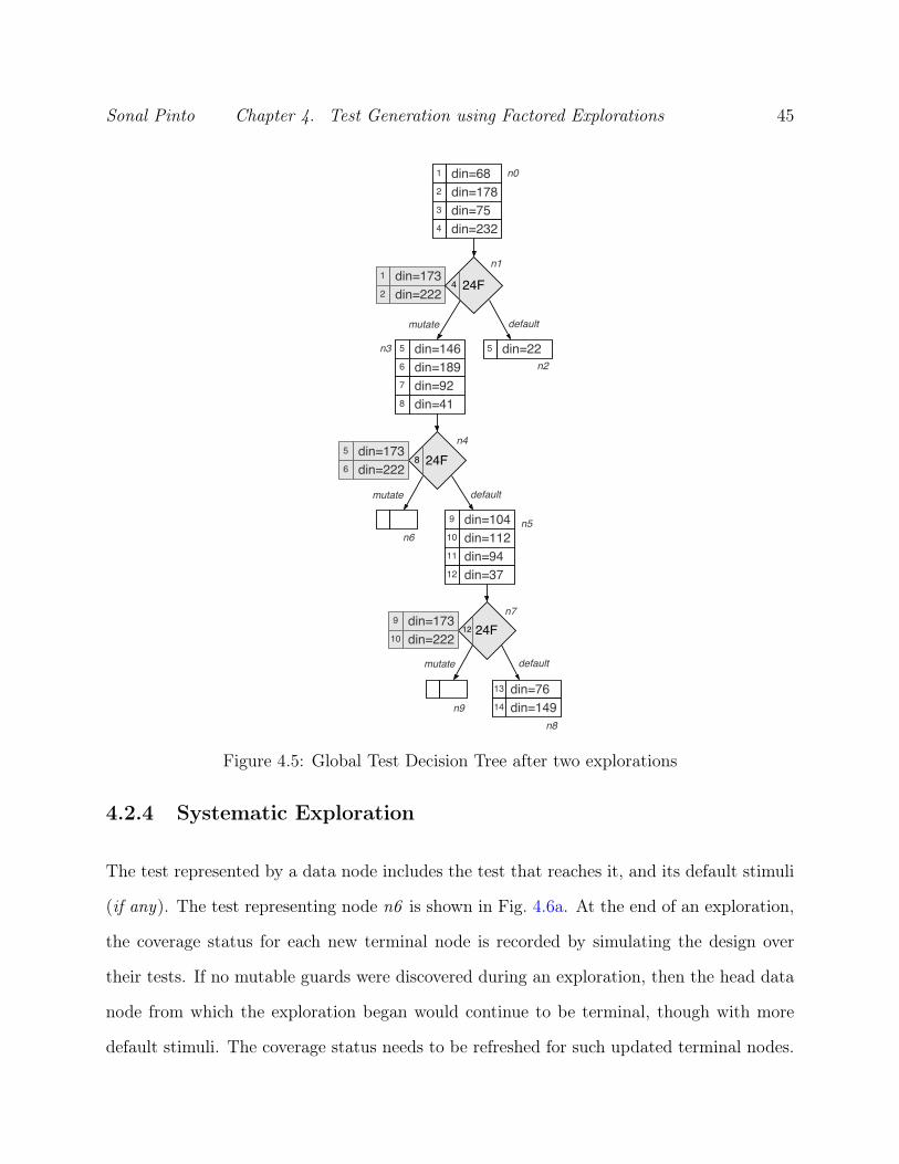
Sonal Pinto Chapter 4. Test Generation using Factored Explorations 45
Figure 4.5: Global Test Decision Tree after two explorations
4.2.4 Systematic Exploration
The test represented by a data node includes the test that reaches it, and its default stimuli
(if any). The test representing node n6 is shown in Fig. 4.6a. At the end of an exploration,
the coverage status for each new terminal node is recorded by simulating the design over
their tests. If no mutable guards were discovered during an exploration, then the head data
node from which the exploration began would continue to be terminal, though with more
default stimuli. The coverage status needs to be refreshed for such updated terminal nodes.

Sonal Pinto Chapter 4. Test Generation using Factored Explorations 46
(a) Test for node n6 (b) Final test output
Figure 4.6: Tests derived from the TDT and their branch coverage
The TG currently employs three heuristic metrics to select the next terminal node for each
exploration.
• Random Path Selection (RPS): This selection heuristic was introduced in KLEE [5].
A terminal node is selected by traversing the TDT, starting from the root with random
choices made at every branch. This strategy is expected to uncover easy-to-reach sys-
tem states. Despite being shallow heuristic, a random selection based on TDT traversal
is immune to the effects of loops and state space traps.
• Coverage Oriented Selection (COS): This strategy aims to guide the exploration
along least covered branches in hopes of uncovering unexplored regions of the design.
Say, I branches are covered among all J terminal nodes. And, cij is the coverage
count for branch i in terminal node j. Then, as shown below, a score sj for each node
is calculated from a branch heuristic weight wi. The node with the highest score is

Sonal Pinto Chapter 4. Test Generation using Factored Explorations 47
selected.
Ci =∑∀j∈J cij (4.1)
wi =
∑∀i∈I Ci
Ci
(4.2)
sj =∑∀i∈I|cij>0 wi (4.3)
• Target Oriented Selection (TOS): Given a target branch, TOS restricts a COS
type heuristic selection to terminal nodes that may possibly reach the target. If a
terminal node is found to cover a branch that offers no path to the target branch
in the design BTG, then it is ignored during selection. Such ignored nodes denote
tests that proceed the control flow along paths of the FSM away from the target
state. Restricting the coverage oriented heuristic to viable nodes has a better chance
of guiding the test generation effort towards the target.
The concluding task for the Test Generator (TG) is to derive the test from the global Test
Decision Tree (TDT). Writing out the optimal test can be boiled down to selecting the
optimal set of data nodes in the TDT that cover all explored branches with the minimal
number of input vectors. The technique of deriving the optimal test from the TDT removes
the requirement to use standard test compaction techniques [23], thereby further reducing
the overall functional testing time.
We utilize a greedy approach for handling this operation. With a breadth-first traversal, we
collect a list of data nodes, M , that were the first at discovering a branch, until M includes
nodes that cover all discovered branches, I. The test, Tj represented by each node-j includes
the test that reaches it and its default stimuli. Algorithm 1 shows the greedy accumulation of
vectors among M , to build the final test, T . Concluding our example, the final test written

Sonal Pinto Chapter 4. Test Generation using Factored Explorations 48
out will only consist of n3 as it covers all branches (specifically, branch-4 in cycle-4, and
branch-5 in cycle-8). A test of length, 9 (Fig. 4.6b) is built concatenating the initialization
vector and the 8-cycle test represented by n3.
Algorithm 1 Derive Final Test from the TDTI = set of all unique branches covered in the TDTM = data nodes that first-discovered some branch ∈ INj = set of branches covered by node j ∈M , of size nj
Tj = test represented by j ∈M , of length tjTinit = initialization vectors
RequiredTest , T = ∅,Let, k ∈Mwhile I 6= ∅ do
for each j ∈M doif (nj > nk) ∨ (nj = nk ∧ tj < tk) then
k = j
T = T + Tinit + Tk
I = I −Nk
for each j ∈M doNj = Nj −Nk
4.3 Experimentation and Results
CORT is written in Python (v3.4.3) and uses the Z3Py Python interface to Z3 (v4.5.1) [34],
an SMT solver from Microsoft Research. The design information parsed and generated by
the Preprocessor is stored as Python objects (Python pickling) in binary format to be read
in further stages. The simulator source code which includes the Verilator C++ translation of
the RTL and its harness generated by the Preprocessor is compiled as shared library object
that can be imported as a Python module. All experiments are run on a Linux (Lubuntu
15.10) machine with an Intel Core i7-975 (3.33GHz) with 6GB memory. We present CORT’s
performance in terms of branch coverage, test length and execution time over benchmarks

Sonal Pinto Chapter 4. Test Generation using Factored Explorations 49
from ITC99 [8] (row 2-8) and IWLS-2005 [4] (row 9-14) detailed in Table 4.1.
Table 4.1: Benchmark and CORT Strategy
Bench. PI PO Gates Bran. Unreach.1 Pre.(s) Q R Searchb06 2 6 66 24 1 1.9 1 8 RPSb07 1 8 382 19 1 1.98 1 8 RPS+16xCOSb10 11 6 172 32 1 1.98 4 8 RPS+32xCOSb11 7 6 366 33 1 1.92 4 8 RPS+128xCOS
b12 5 6 1000 105 1 2.12 1 128 RPS+TOS(c1)+TOS(c2)
b14 32 54 3461 211 12 2.14 8 8 RPS+128xCOSb15 36 70 6931 149 1 2.15 8 16 RPS+128xCOS
ss_pcm 17 9 470 19 0 1.99 2 4 RPS+128xCOSusb_phy 13 18 546 144 0 2.1 4 8 RPS+192xCOS
sasc 14 12 549 58 0 1.99 4 8 RPS+128xCOSsimple_spi 14 12 821 81 1 1.98 4 8 RPS+128xCOS
i2c 16 14 1142 112 0 2.07 4 20 RPS+192xCOSspi 45 45 3227 89 0 2.02 4 8 RPS+192xCOS
1 Statically determined unreachable branches (Section 3.2)
4.3.1 Search Strategy
The benchmark circuits used and the parameters set for each circuit are described in Ta-
ble 4.1. The number of branches instrumented by Verilator is shown in column 4 (Bran.).
During preprocessing, we also statically analyze the use-definition chains in the parsed Ab-
stract Syntax Tree to determine unreachable branches (column 6) as described in Section 3.2.
These may not include all possible unreachable branches. The one-time cost for preprocess-
ing inclusive of the simulator compilation is shown in column 7 (Pre.). The individual
exploration for each design is bound by exploration-radius (R) and exploration-overlap (Q),
selected as per design complexity and size. These parameters are experimentally determined
with a minimum of Q = 1 and R = 4 and are increased until the trials for test generation
results in high branch coverage (aim: >95%).

Sonal Pinto Chapter 4. Test Generation using Factored Explorations 50
Search in column 10, describes the quantity and type of the iterative selection method for
each exploration. We begin growing the TDT for each design with repeated rounds of RPS
until no new coverage points are discovered (for four rounds). The actual number of RPS
iterations during test-generation is non-deterministic and thus is simply mentioned as RPS.
This is usually followed by multiple explorations using COS, selected as per design size.
A description of RPS+N×COS implies that N explorations using the COS strategy were
pursued after exhausting RPS. Almost all designs are suitably covered by using RPS and
COS alone. For b12, a single player game of guessing a sequence, a TOS for the branches
representing hard-to-reach states c1 and c2 [20, 32] is repeated, until the targets are covered.
A relatively larger exploration radius is set for b12 because the primary inputs are only used
in guards, offering low concolic execution complexity.
4.3.2 Branch Coverage
CORT results are compared against HYBRO [17], [25] and BEACON [20] in Table 4.2. For
unreported benchmarks in HYBRO and [25], NA is placed. Columns 5 and 11 highlights
the branch coverage (overall) and test length for CORT. Column 9 describes the time taken
by CORT for executing the search strategy and generating the test for each benchmark and
excludes the preprocessing cost. Column 12 (Reach. BC% ) represents the CORT’s branch
coverage only accounting for reachable branches. A quick glance shows that our work, despite
relying on interleaved concrete and symbolic constraint solving, demonstrates significantly
shorter test generation time and achieves a high RTL branch coverage. A fewer number of
vectors are generated for the same goal of maximal branch coverage compared to BEACON,
a search-based test generator. The minor differences in coverage between tools could be
attributed to instrumentation differences and optimizations.

Sonal Pinto Chapter 4. Test Generation using Factored Explorations 51
Table 4.2: Performance Comparison with Previous Work
Bench. Branch Coverage1 % Run Time(s) #Vectors2 Reach.HYBRO [25] BEACON CORT HYBRO [25] BEACON CORT BEACON CORT BC%3
b06 94.12 96.3 95.83 95.83 0.1 0.55 0.0054 0.12 1731 18 100b07 NA NA 90 90 NA NA 0.37 0.05 759 46 94.74b10 96.77 96.77 93.75 96.88 52.14 24.61 11.4 0.52 3547 28 100b11 91.3 94.44 96.88 96.97 326.85 270.28 11.95 3.11 1213 430 100b12 NA NA 98.09 98.09 NA NA 111.42 35.23 37006 35081 99.04b14 83.5 98.95 91.94 93.36 301.69 257.59 204.65 40.98 4381 573 98.991 Number of branches present in the RTL may vary between compared methods due to in-strumentation differences. Represents overall branch coverage.2 Test length was not reported for HYBRO [17] and [25].3 Reachable branch coverage for CORT
Consider design b10 where CORT achieves a high branch coverage score (96.88% overall,
100% reachable branches) on par with HYBRO and [25] in only 0.52s. Although HYBRO,
[25], and CORT base their test generation effort on hybrid concrete and symbolic simulation,
our work is more than 40× faster for b10 alone. For b14, we compare CORT with BEACON
which also uses Verilator for instrumentation and simulation. We achieve a higher coverage
(93.36% overall, 99% reachable branches) with a test which is 7.5× smaller.
Concerning the target-oriented test generation, CORT consistently manages to cover states
c1 and c2 in b12. Satisfying c1 requires timing-out by not pressing the input (k). The deepest
system state in b12, c2 (WIN, state variable gamma = 25), which requires over 30000 cycles
in a comparable time to PACOST [32] (single-cycle: 54.22s, multi-cycle: 169.83s). Reaching
the winning state requires guessing the correct input over 500 times in sequence. Pressing
the wrong key in the sequence traps the system in LOSS (state variable gamma = 23) unless
reset or restarted. Thus, nodes in the TDT that have reached states that offer no path to c2
in the BTG for b12 are ignored during selection for new TOS(c2) explorations. Nonetheless,
the TDT represents the entire control-flow response of the system, and thus the final test is
written out covers c1, c2, and LOSS. Concolic execution based directed test generators that
only rely on fixed unrolling like HYBRO and [25] are unable to reach such deep targets.

Sonal Pinto Chapter 4. Test Generation using Factored Explorations 52
Table 4.3: Extended Performance Comparison
Bench.Stochastic Search-Based Hybrid Concrete×Symbolic Reach.3
RAND1 BEACON CORT2 CORTBC% BC% Vec. Time(s) BC% Vec. Time(s) BC%
b15 42.13 89.93 38234 6.88 92.62 367 27.7 93.24ss_pcm 100 100 393 2.98 100 61 2.76 100usb_phy 82.64 82.64 3918 5.67 84.72 764 75.15 84.72
sasc 91.67 91.67 278 4.06 91.67 68 16.48 91.67simple_spi 98.3 97.53 5566 4.32 98.77 663 104.2 100
i2c 83.27 87.5 6445 5.01 87.5 1188 430.38 87.5spi 90.31 100 1180 7.36 100 71 28.6 100
1 Test consists of random input vectors generated for 50k cycles2 CORT, written in Python is compared against C++ based BEACON3 Reachable branch coverage for CORT
Table 4.3 shows results of test generation on the remaining benchmarks for which results for
HYBRO and [25] were not available. Hence, we compare CORT against random test gener-
ation (RAND), and BEACON configured to the settings used in [20]. RAND is constrained
to non-reset primary inputs for 50000 cycles and averaged across eight trials to represent a
baseline. The table highlights the best results from BEACON and CORT. BC% (overall),
Vec. and Time represent percentage branch coverage, test length and runtime respectively.
Reach. BC% describes CORT’s branch coverage without accounting for guaranteed unreach-
able branches.In all cases, the result from CORT matches or exceeds the compared methods
in terms of coverage and test length. The design, b15 contains a 16-byte prefetch queue
(array) through which both instructions (80386 opcodes) and data are buffered. Random
test generation is unable to handle such sequential depth in the control-flow. BEACON
almost covers as many branches (89.93%) as CORT (92.62% overall, 93.24% reachable) but
requires notably more vectors to do so (almost 100×).
Although CORT is not as fast as stochastic search-based techniques like BEACON for these
circuits, the tests generated are undoubtedly efficient in terms of coverage per vector. This
is within our expectation, as CORT is a Python-based semi-formal methodology relying on

Sonal Pinto Chapter 4. Test Generation using Factored Explorations 53
costly SMT operations. Nonetheless, in comparison to the same class of techniques that
use hybrid concrete and symbolic simulation (HYBRO, [25]), CORT is remarkably faster.
These results are indicative of CORT’s ability to generate minimal directed tests for practical
Verilog designs.
4.3.3 Effects of Exploration Length
Table 4.4: Effects of Exploration Length for b15
Q R Q+R BC% Vec. Time(s)2 2 4 84.73 288 2.134 4 8 88.42 261 4.628 8 16 90.60 374 9.828 16 24 91.44 426 16.5716 16 32 91.52 401 20.5116 32 48 91.61 472 40.73
In Table 4.4, for a fixed search strategy of 64×COS, the exploration radius (R) and explo-
ration overlap (Q) are varied for the design, b15. An increasing exploration length (R+Q)
is analyzed, and the average branch coverage (BC%, overall), test length (Vec.) and runtime
(Time) are reported over 8 trials. Our experiments show that a suitably sized exploration
is necessary for generating efficient tests. With shorter exploration lengths (row 2-3), we
discover fewer branches in the same search. However, these tests require fewer vectors to
cover those branches, highlighting the utility of deriving the overall test from the TDT.
Finding the suitable exploration length is a matter of experimentation and knowledge of
design complexity. A smaller Q leads to discovering fewer mutable guards per exploration
and thus, longer tests, which is indicative of a greater reliance on the randomness of the
concrete stimuli (R) to reach certain branches. On the other hand, an exploration with a
high Q is computationally intensive and demands a high execution time.

Sonal Pinto Chapter 4. Test Generation using Factored Explorations 54
It is seen that an exploration length of 24 (row 5) optimally leverages all goal metrics. The
efficiency of the test generation effort stagnates beyond a certain an exploration length,
indicating its sufficiency at handling the design complexity. Lastly, row 7 (Q = 16, R = 32)
shows a larger final test length, which is an adverse effect of the greedy test accumulation
technique.

Chapter 5
Conclusion
5.1 Limitations and Future Work
In our work, the concrete values of variables can only be read between, not during, cycles.
In the same cycle, if a variable is used in a statement between two blocking definitions of
the same variable, then no valid (pre/post cycle) concrete values can read for its use. When
the CEE encounters such a situation in the concrete path, it is reported to the user, and the
program terminates. The user is expected to insert a temporary internal variable in the RTL
to mirror the first blocking definition. This adds no functional value and does not increase
the size of the synthesized design, but is quite helpful for concolic execution. Converting
the C++ RTL to Static Single Assignment (SSA) form would solve this problem, and is
expected in our future work.
Secondly, our work is limited to RTL designs containing signals with a maximum width of 64
bits. This limitation is posed by Verilator’s handling of large-width signals as contiguous C
arrays. The capability to handle such signals and their assignments is also being considered
55

Sonal Pinto Chapter 5. Conclusion 56
for future work. In hardware RTL, the sequential memory elements like registers usually
change their values are their trigger clock edges. In our methodology, the RTL is translated
to C++, where this RTL feature (non-blocking statements in Verilog) is mimicked by using
temporary variables which are function scoped (and not declared at the top class level). This
requires extended evaluation effort where the RTL Control Flow Graph is analyzed to infer
resolution of these temporary variables and see their effect in actual named signals (available
at the top class). The immediate solution to this would be to scope these temporary variables
to the top simulator class, but would required severe modification to the Verilator compiler
source code.
Lastly, CORT is written in Python as a proof of concept and will be reconstructed in C++
for performance.
While developing our work we curated certain ideas that could help enhance concolic execu-
tion based testing methodology. They are listed as follows.
• While the Test Decision Tree (TDT) excellently abstracts the control-flow response of
the design in terms of stimuli, it does not account for system states. In reality, designs
have a limited number of functionally reachable system states, and these are often
revisited. The TDT needs to be extended to support the identification of system states,
possibly abstracted to control signals. Additional edges should be added showing a loop
of the control flow back to previously visited system states, implying the response needs
to be recorded in the form of a graph rather than a tree.
• Upon simulation, the control flow executed through a unique path in the CFG. A
cost metric that is based on maximizing all unique single-cycle paths discovered could
be a better search heuristic than branch coverage alone. Single-cycle path coverage
encompasses branch coverage and may offer more differentiation between solutions

Sonal Pinto Chapter 5. Conclusion 57
that need to be selected.
5.2 Conclusion
In this thesis, we proposed a novel concolic execution methodology for the Register Trans-
fer Level (RTL). We strongly intertwine symbolic execution and concrete simulation, and
dynamically construct symbolic constraints in a cycle-by-cycle functional simulation. Our
symbolic analysis is lean and restricted to primary input stimulated regions of the RTL.
Traditionally, a path constraint would be built over the entire concrete trace, extracted after
concrete simulation. However, the simulator used in our work is instrumented for direct
access of all signals in the design at any time. Furthermore, the simulator is enhanced to
record the concrete trace in terms of branch IDs during simulation. Unstimulated variables
in statements are concretely read from the simulator and substituted in-place to construct
symbolic expressions. This reduces the overall computational complexity of our formal anal-
ysis component. The base cycle-by-cycle concolic execution methodology is tested against
previous work and is demonstrated to be significantly superior.
We have presented CORT; a factored concolic execution based test generation technique for
the Register Transfer Level. Our method tightly interleaves concrete simulation and sym-
bolic evaluation at a cycle-by-cycle level, providing advantageous performance over previous
hybrid techniques. Our minimalist approach to concolic execution, where we dynamically
evaluate primary-input stimulated statements, allows us to explore the search space effort-
lessly. Furthermore, we abstract the control-flow response for the entire test search effort in
a novel representation, the Test Decision Tree (TDT), which is systematically grown over
several factored explorations. We not only use the TDT for strategic guidance for each new
exploration but also derive the optimal test from it without requiring any standard test com-

Sonal Pinto Chapter 5. Conclusion 58
paction techniques. Our results show that CORT generates smaller tests with high branch
coverage, faster than existing hybrid semi-formal methods.

Bibliography
[1] A. Koelbl, J. H. Kukula, and R. Damiano, "Symbolic RTL simulation," in Proc. of
Design Automation and Test Europe Conference, 2001, pp. 47-50.
[2] A. Biere, A. Cimatti, E. M. Clarke, and Y. Zhu, "Symbolic model checking without
BDDs," in Proc. of International Conference on Tools and Algorithms for Construction
and Analysis of Systems, 1999, pp. 193-207.
[3] B. Beizer, "Software testing techniques (2nd ed.)," Van Nostrand Reinhold Co., USA,
1990.
[4] C. Albrecht, "IWLS 2005 Benchmarks," International Workshop on Logic Synthesis,
2005.
[5] D. Dunbar, C. Cadar, and D. Engler, "KLEE: unassisted and automatic generation
of high-coverage tests for complex systems programs," in Proc. of the 8th USENIX
conference on Operating Systems Design and Implementation, 2008, pp. 209-224.
[6] D. Krishnaswamy, M. S. Hsiao, V. Saxena, E. M. Rudnick, J. H. Patel and P. Banerjee,
"Parallel genetic algorithms for simulation-based sequential circuit test generation," in
Proc. of Tenth International Conference on VLSI Design, Hyderabad, 1997, pp. 475-481.
59
Sonal Pinto Bibliography 60
[7] E. Clarke, A. Biere, R. Raimi, and Y. Zhu, "Bounded model checking using satisfiability
solving," Formal Methods in System Design, 2001, pp. 7-34.
[8] F. Corno, M.S. Reorda, G. Squillero, "RT-level ITC’99 benchmarks and first ATPG
results," in Proc. of the IEEE Design and Test of Computers, 2000, vol. 17, no. 3, pp.
44-53.
[9] F.E. Allen, "Control flow analysis," SIGPLAN Not., 1970, vol. 5, no. 7, pp. 1-19.
[10] F. Corno, M. S. Reorda, G. Squillero, A. Manzone, and A. Pincetti, âĂIJAutomatic test
bench generation for validation of rt-level descriptions: an industrial experience,âĂİ in
Proc. of Design Automation and Test Europe Conference, 2000, pp. 385âĂŞ389.
[11] J. Burnim and K. Sen, âĂIJHeuristics for Scalable Dynamic Test Generation,âĂİ in
Automated Software Engineering, 2008, pp. 443âĂŞ446.
[12] J. Wegener, A. Baresel, H. Sthamer, "Evolutionary Test Environment for Automatic
Structural Testing," Information and Software Technology, Special Issue devoted to the
Application of Metaheuristic Algorithms to Problems in Software Engineering, 2001,
vol. 43, pp. 841-854.
[13] K. Sen, D. Marinov, and G. Agha, "CUTE: a concolic unit testing engine for C," in
Proc. of the 10th European Software Engineering Conference held jointly with 13th ACM
SIGSOFT international symposium on Foundations of Software Engineering, 2005, pp.
263-272.
[14] K. Gent and M. S. Hsiao, "Abstraction-based relation mining for functional test gener-
ation," IEEE VLSI Test Symposium, 2015, pp. 1-6.
[15] K. Gent and M. S. Hsiao, "Functional Test Generation at the RTL Using Swarm Intelli-
gence and Bounded Model Checking," 22nd Asian Test Symposium, 2013, pp. 233-238.

Sonal Pinto Bibliography 61
[16] L. Liu and S. Vasudevan, "STAR: Generating input vectors for design validation by
static analysis of RTL," in Proc. High Level Design Validation Test Workshop, 2009,
pp. 32-37.
[17] L. Liu and S. Vasudevan, "Efficient validation input generation in RTL by hybridized
source code analysis," Design, Automation and Test in Europe, 2011, pp. 1-6.
[18] L. Zhang, M. R. Prasad, and M. S. Hsiao, "Incremental deductive and inductive rea-
soning for SAT-based bounded model checking," in Proc. of the IEEE International
Conference on Computer Aided Design, November 2004, pp. 502-509.
[19] P. Godefroid, N. Klarlund, and K. Sen, "DART: directed automated random testing,"
in Proc. of the ACM SIGPLAN conference on Programming Language Design and Im-
plementation, 2005, pp. 213-223.
[20] M. Li, K. Gent and M. S. Hsiao, "Design validation of RTL circuits using evolutionary
swarm intelligence," IEEE International Test Conference, 2012, pp. 1-8.
[21] M. S. Hsiao, E. M. Rudnick and J. H. Patel, "Sequential circuit test generation using
dynamic state traversal," in Proc. of European Design and Test Conference,1997, pp.
22-28.
[22] M. S. Hsiao, E. M. Rudnick, and J. H. Patel, "Dynamic state traversal for sequential
circuit test generation," ACM Trans. on Design Automation of Electronic Systems, 2000,
pp. 548-565.
[23] M. S. Hsiao, E. M. Rudnick, and Janak H. Patel, "Fast static compaction algorithms
for sequential circuit test vectors," IEEE Tran. on Computers, 1999, vol. 48, no. 3, pp.
311-322.
Sonal Pinto Bibliography 62
[24] P. McMinn and M. Holcombe, "Evolutionary testing of state-based programs," in Proc.
of the 7th annual conference on Genetic and evolutionary computation (GECCO ’05),
Hans-Georg Beyer (Ed.), ACM, pp. 1013-1020.
[25] Q. Xiaoke and P. Mishra, "Scalable Test Generation by Interleaving Concrete and Sym-
bolic Execution," in International Conference on VLSI Design and International Con-
ference on Embedded Systems, 2014, pp. 104-109.
[26] R. Ferguson and B. Korel, "Software test data generation using the chaining approach,"
in Proc. of 1995 IEEE International Test Conference (ITC), 1995, pp. 703-709.
[27] R. Arora and M. S. Hsiao, "Enhancing SAT-based bounded model checking using se-
quential logic implications," in Proc.s of the IEEE VLSI Design Conference, January,
2004, pp. 784-787.
[28] S. Bagri, K. Gent and M. S. Hsiao, "Signal domain based reachability analysis in RTL
circuits," Sixteenth International Symposium on Quality Electronic Design, 2015, pp.
250-256.
[29] T. Zhang, T. Lv and X. Li, "An abstraction-guided simulation approach using Markov
models for microprocessor verification," in Proc. of Design, Automation & Test in Eu-
rope Conference & Exhibition (DATE ’10), 2010, pp. 484-489.
[30] T. Niermann and J. H. Patel, "HITEC: a test generation package for sequential circuits,"
in Proc. of the conference on European design automation (EURO-DAC ’91). IEEE
Computer Society Press, 1991, pp. 214-218.
[31] V. V. Acharya, S. Bagri and M. S. Hsiao, "Branch guided functional test generation at
the RTL," in IEEE European Test Symposium, 2015, pp. 1-6.

Sonal Pinto Bibliography 63
[32] Y. Zhou, T. Wang, H. Li, T. Lv and X. Li, "Functional Test Generation for Hard-
to-Reach States Using Path Constraint Solving," in IEEE Tran. on Computer-Aided
Design of Integrated Circuits and Systems, 2016, vol. 35, no. 6, pp. 999-1011.
[33] Y. Zhou, T. Wang, T. Lv, H. Li and X. Li, "Path Constraint Solving Based Test
Generation for Hard-to-Reach States," 22nd Asian Test Symposium, 2013, pp. 239-244.
[34] Microsoft Research, "Z3 theorem prover," https://z3.codeplex.com/
[35] SRI International Computer Science Laboratory, "The Yices SMT Solver,"
http://yices.csl.sri.com/
[36] W. Snyder, D. Galbi and P. Wasson, "Verilator,"
https://www.veripool.org/wiki/verilator