RTL Combinatorial Components - cecs.uci.edugajski/eecs31/slides/Digital... · Combinatorial RTL...
30
Copyright © 2010-2013 by Daniel D. Gajski EECS 31/CSE31, University of California, Irvine Principles Of Digital Design Combinatorial RTL Components Computation and Reorganization Arithmetic and Comparison Components Logic Components Selection Components Encoding/Decoding Components Bit manipulation
-
Upload
nguyentruc -
Category
Documents
-
view
231 -
download
2
Transcript of RTL Combinatorial Components - cecs.uci.edugajski/eecs31/slides/Digital... · Combinatorial RTL...
Copyright © 2010-2013 by Daniel D. Gajski EECS 31/CSE31, University of California, Irvine
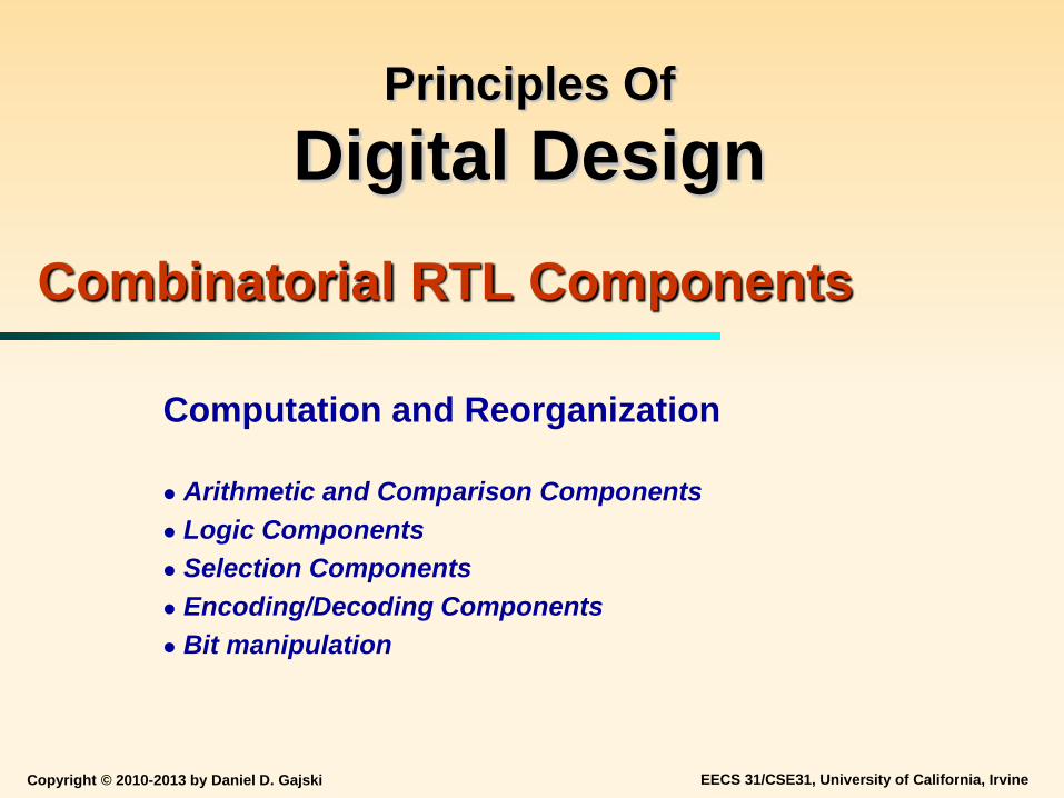
Principles Of Digital Design
Combinatorial RTL Components
Computation and Reorganization Arithmetic and Comparison Components Logic Components Selection Components Encoding/Decoding Components Bit manipulation

Copyright © 2010-2013 by Daniel D. Gajski EECS 31/CSE31, University of California, Irvine 2
Digital RTL Components
Digital components are divided into Combinatorial components Easy to design, partition, and test
Sequential components
Combinatorial Logic Circuit (Logic Gates)
Combinatorial Logic Circuit (Logic Gates)
outputs = f (inputs)
outputs = f (inputs, time)
Memory
●●● ●●●
●●● ●●●
n inputs m outputs
n inputs m outputs

Copyright © 2010-2013 by Daniel D. Gajski EECS 31/CSE31, University of California, Irvine 3
Combinatorial RTL Components Data Transformation Components
Arithmetic Operation (Add, Subtract, Multiply, Divide) Data Comparison (Greater-than, Equal, Less-than,…) Logic Operation (AND, OR, NOT,…) Bit Manipulation (Shift, Rotate, Extract,…)
Interconnection Components
Source and Destination Selection Bus Connections and Interface
Data Conversion Components
Data Encoding (Unary to Binary) Data Decoding (Binary to Unary)
Copyright © 2010-2013 by Daniel D. Gajski EECS 31/CSE31, University of California, Irvine 4
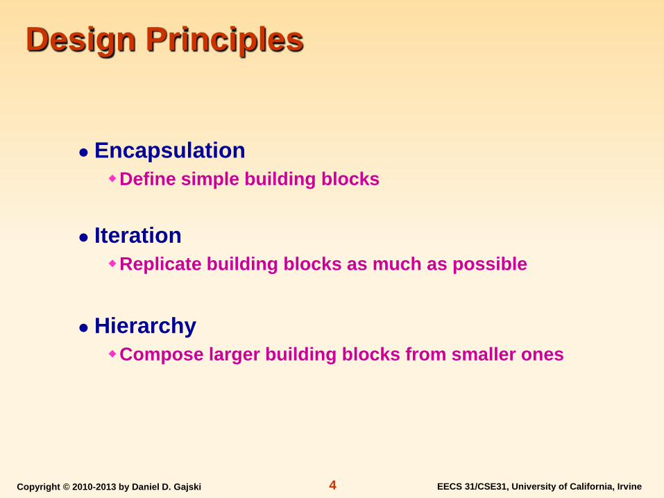
Design Principles
Encapsulation Define simple building blocks
Iteration Replicate building blocks as much as possible
Hierarchy Compose larger building blocks from smaller ones
Copyright © 2010-2013 by Daniel D. Gajski EECS 31/CSE31, University of California, Irvine 5
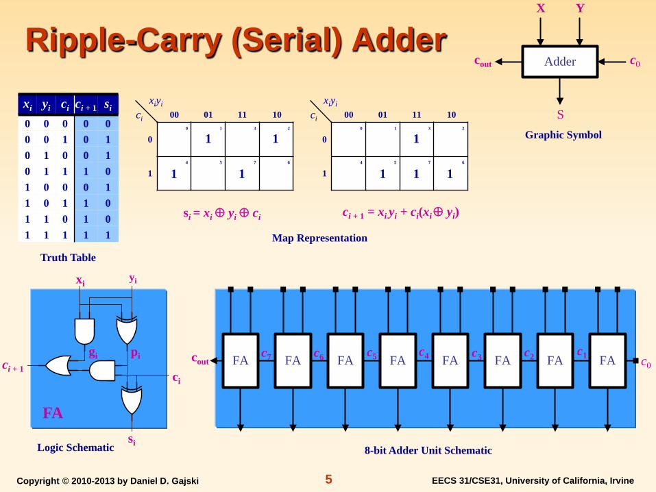
Ripple-Carry (Serial) Adder xi yi ci ci + 1 si 0 0 0 0 0 0 0 1 0 1 0 1 0 0 1 0 1 1 1 0 1 0 0 0 1 1 0 1 1 0 1 1 0 1 0 1 1 1 1 1
Truth Table
xi yi
ci
si
ci + 1
ci + 1 = xi yi + ci(xi ⊕ yi)
si = xi ⊕ yi ⊕ ci
1
0 0 1 3 2
4 5 7 6
10 11 01 00 xiyi
ci
1
1 1 1 1
0 0 1 3 2
4 5 7 6
10 11 01 00 xiyi
ci
1 1
1 1
FA
c0 cout
Map Representation
Graphic Symbol
Logic Schematic 8-bit Adder Unit Schematic
FA FA FA FA FA FA FA FAc1 c2 c3 c4 c5 c6 c7
X Y
c0
S
cout Adder
pi gi

Copyright © 2010-2013 by Daniel D. Gajski EECS 31/CSE31, University of California, Irvine 6
Ripple-Carry (Serial) Adder xi yi ci ci + 1 si 0 0 0 0 0 0 0 1 0 1 0 1 0 0 1 0 1 1 1 0 1 0 0 0 1 1 0 1 1 0 1 1 0 1 0 1 1 1 1 1
Truth Table
xi yi
ci
si
ci + 1
si = xi ⊕ yi ⊕ ci
1
0 0 1 3 2
4 5 7 6
10 11 01 00 xiyi
ci
1
1 1 1 1
0 0 1 3 2
4 5 7 6
10 11 01 00 xiyi
ci
1 1
1 1
FA
c0 cout
Map Representation
Graphic Symbol
Logic Schematic 8-bit Adder Unit Schematic
FA FA FA FA FA FA FA FAc1 c2 c3 c4 c5 c6 c7
X Y
c0
S
cout Adder
pi gi
ci + 1 = xi yi + ci(xi ⊕ yi)

Copyright © 2010-2013 by Daniel D. Gajski EECS 31/CSE31, University of California, Irvine 7
Two’s Complement Adder/Subtractor
Truth Table
8-bit Adder/Subtractor Unit Schematic
Two’s complement subtraction A – B = A + B′ + 1
Subtraction Procedure Complement B Set input carry to 1 Add to A
S Function Comment
0 A + B Addition
1 A + B′ + 1 Subtraction
A B
F
Graphic Symbol
Adder/Subtratorcout
S
cout
S
a0 b0 a1 b1 a2 b2 a3 b3 a4 b4 a5 b5 a6 b6 a7 b7
f0 f1 f2 f3 f4 f5 f6 f7
FA FA FA FA FA FA FA FA
Copyright © 2010-2013 by Daniel D. Gajski EECS 31/CSE31, University of California, Irvine 8
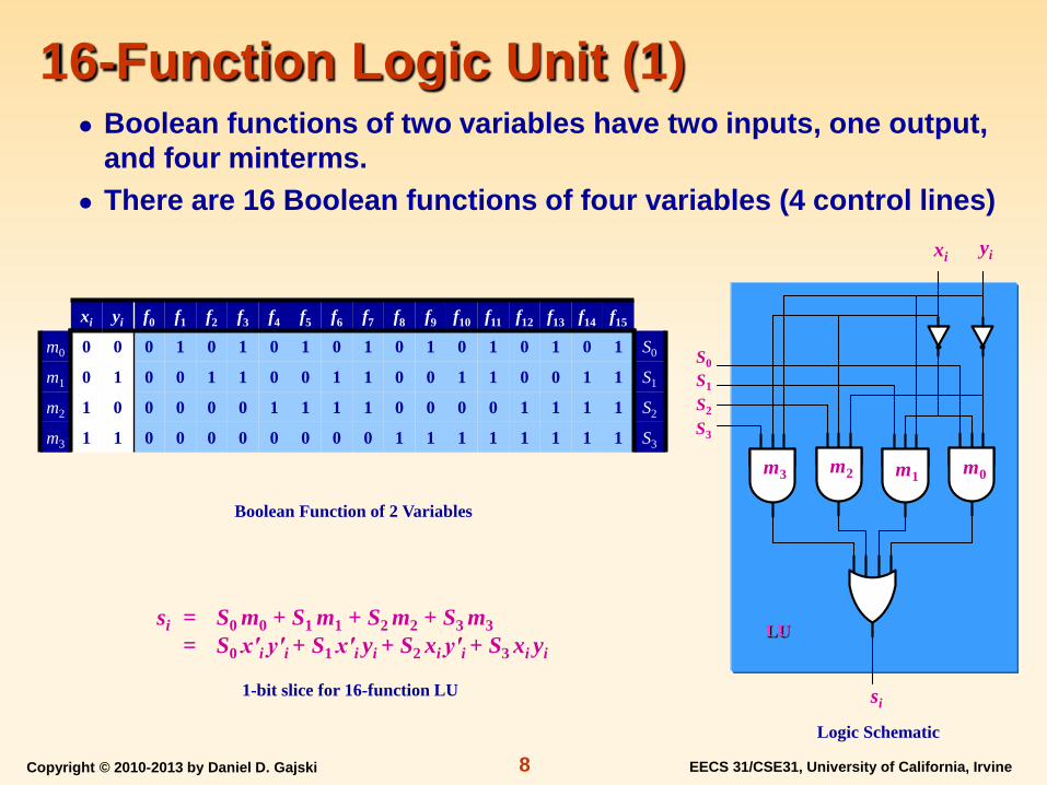
16-Function Logic Unit (1) Boolean functions of two variables have two inputs, one output,
and four minterms. There are 16 Boolean functions of four variables (4 control lines)
si = S0 m0 + S1 m1 + S2 m2 + S3 m3
= S0 x′i y′i + S1 x′i yi + S2 xi y′i + S3 xi yi
xi yi f0 f1 f2 f3 f4 f5 f6 f7 f8 f9 f10 f11 f12 f13 f14 f15 m0 0 0 0 1 0 1 0 1 0 1 0 1 0 1 0 1 0 1 S0
m1 0 1 0 0 1 1 0 0 1 1 0 0 1 1 0 0 1 1 S1
m2 1 0 0 0 0 0 1 1 1 1 0 0 0 0 1 1 1 1 S2
m3 1 1 0 0 0 0 0 0 0 0 1 1 1 1 1 1 1 1 S3
Logic Schematic
Boolean Function of 2 Variables
xi yi
si
LU
S0 S1
S2
S3
1-bit slice for 16-function LU
m0 m1 m2 m3

Copyright © 2010-2013 by Daniel D. Gajski EECS 31/CSE31, University of California, Irvine 9
16-Function Logic Unit (2)
8-bit Logic Unit Schematic Graphic Symbol
X Y
F
S0 S1 S2 S3
Logic Unit
Boolean functions of two variables have two inputs, one output, and four minterms.
There are 16 Boolean functions of four variables (4 control lines)
si = S0 m0 + S1 m1 + S2 m2 + S3 m3 = S0 x′i y′i + S1 x′i yi + S2 xi y′i + S3 xi yi
S0
x0 y0 x1 y1 x2 y2 x3 y3 x4 y4 x5 y5 x6 y6 x7 y7
s0 s1 s2 s3 s4 s5 s6 s7
S1 S2 S3
LU LU LU LU LU LU LU LU
Copyright © 2010-2013 by Daniel D. Gajski EECS 31/CSE31, University of California, Irvine 10
2-bit Magnitude Comparator 0 1 3 2
4 5 7 6
12 13 15 14
8 9 11 10
10 11 01 00
01
00
10
11
1 1 1
1 1
1
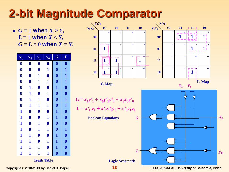
x1 x0 y1 y0 G L 0 0 0 0 0 0 0 0 0 1 0 1 0 0 1 0 0 1 0 0 1 1 0 1 0 1 0 0 1 0 0 1 0 1 0 0 0 1 1 0 0 1 0 1 1 1 0 1 1 0 0 0 1 0 1 0 0 1 1 0 1 0 1 0 0 0 1 0 1 1 0 1 1 1 0 0 1 0 1 1 0 1 1 0 1 1 1 0 1 0 1 1 1 1 0 0
0 1 3 2
4 5 7 6
12 13 15 14
8 9 11 10
10 11 01 00
01
00
10
11
y1y0 x1x0
1
1 1 1
1 1
L Map
Truth Table
G = x1y′1 + x0y′1y′0 + x1x0y′0
y1y0 x1x0
L = x′1 y1 + x′1x′0y0 + x′0y1y0
Logic Schematic
G = 1 when X > Y, L = 1 when X < Y, G = L = 0 when X = Y.
y1
G
L
x1
x0
y0
G Map
Boolean Equations

Copyright © 2010-2013 by Daniel D. Gajski EECS 31/CSE31, University of California, Irvine 11
8-bit Magnitude Comparator
Serial Implementation (n comparator delays)
G7
L7
y0 x0
Larger magnitude comparators can be constructed from basic 2-bit comparators using the following equations
Gi = (xi > yi) OR ((xi = yi) AND (Gi – 1 > Li – 1)) Li = (xi < yi) OR ((xi = yi) AND (Gi – 1 < Li – 1))
G6
L6
G5
L5
G4
L4
G3
L3
G2
L2
G1
L1
G
L
G
L
G
L
G
L
G
L
G
L
G
L
G L G L G L G L
G L G L
G L
y1 x1 y2 x2 y3 x3 y4 x4 y5 x5 y6 x6 y7 x7
y0 x0 y1 x1 y2 x2 y3 x3 y4 x4 y5 x5 y6 x6 y7 x7
Parallel Implementation (log(n) comparator delays)
G7 L7

Copyright © 2010-2013 by Daniel D. Gajski EECS 31/CSE31, University of California, Irvine 12
2-to-1 Selector
Boolean Expression Logic Schematic
S Y
0 D0
1 D1
Selectors (Multiplexers) are used for selecting one of many sources of data
Y = S′D0 + S D1
Truth Table
Graphic Symbol Selector
Y
D0
S 0 1
D1
S D1
Y
D0

Copyright © 2010-2013 by Daniel D. Gajski EECS 31/CSE31, University of California, Irvine 13
4-to-1 Selector
Logic Schematic
Truth Table
S1 S0 Y
0 0 D0
0 1 D1
1 0 D2
1 1 D3
Graphic Symbol
Boolean Expression
Y = S′1S′0D0 + S′1S0 D1 + S1S′0D2 + S1S0D3
Selector
Y
D0
S0 0 3
D3
2 1
D1 D2
S1
S1 D1
Y
D0 D3 D2 S0
Copyright © 2010-2013 by Daniel D. Gajski EECS 31/CSE31, University of California, Irvine 14
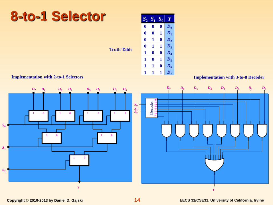
8-to-1 Selector S2 S1 S0 Y
0 0 0 D0
0 0 1 D1
0 1 0 D2
0 1 1 D3
1 0 0 D4
1 0 1 D5
1 1 0 D6
1 1 1 D7 Implementation with 2-to-1 Selectors
Truth Table
Implementation with 3-to-8 Decoder
Y
S0 S1 S2 D
ecod
er
D0 D3 D1 D2 D4 D7 D5 D6
7 6
5 4
3 2
1 0
Y
D0 D3
S0
S1
S2
D1 D2 D4 D7 D5 D6
0 1
0 1 0 1
0 1 0 1 0 1 0 1

Copyright © 2010-2013 by Daniel D. Gajski EECS 31/CSE31, University of California, Irvine 15
8-to-1 Selector S2 S1 S0 Y
0 0 0 D0
0 0 1 D1
0 1 0 D2
0 1 1 D3
1 0 0 D4
1 0 1 D5
1 1 0 D6
1 1 1 D7 Implementation with 2-to-1 Selectors
Truth Table
Implementation with 3-to-8 Decoder
Y
1 0 1 D
ecod
er
D0 D3 D1 D2 D4 D7 D5 D6
7 6
5 4
3 2
1 0
Y
D0 D3
1
0
1
D1 D2 D4 D7 D5 D6
0 1
0 1 0 1
0 1 0 1 0 1 0 1
Copyright © 2010-2013 by Daniel D. Gajski EECS 31/CSE31, University of California, Irvine 16
Decoder
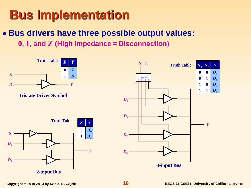
Bus Implementation
4-input Bus
Truth Table S1 S0 Y
0 0 D0
0 1 D1
1 0 D2
1 1 D3
E Y
0 Z
1 D
Bus drivers have three possible output values: 0, 1, and Z (High Impedance ≈ Disconnection)
S Y
0 D0
1 D1
Tristate Driver Symbol
2-input Bus
Truth Table
Truth Table
Y
E
D Y
Y
S
D0
D1
D0
D1
D2
D3
0 3 2 1
S1 S0
Copyright © 2010-2013 by Daniel D. Gajski EECS 31/CSE31, University of California, Irvine 17
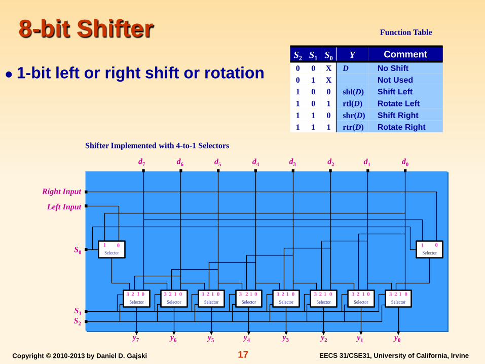
8-bit Shifter Function Table
S2 S1 S0 Y Comment 0 0 X D No Shift 0 1 X Not Used 1 0 0 shl(D) Shift Left 1 0 1 rtl(D) Rotate Left 1 1 0 shr(D) Shift Right 1 1 1 rtr(D) Rotate Right
1-bit left or right shift or rotation
Shifter Implemented with 4-to-1 Selectors
d0 d3 d1 d2 d4 d7 d5 d6
S0
S1 S2
y0 y3 y1 y2 y4 y7 y5 y6
Right Input
Left Input
Selector
Selector
Selector Selector Selector Selector Selector Selector Selector
Selector0 1 0 1
0 3 1 2 0 3 1 2 0 3 1 2 0 3 1 2 0 3 1 2 0 3 1 2 0 3 1 2 0 3 1 2

Copyright © 2010-2013 by Daniel D. Gajski EECS 31/CSE31, University of California, Irvine 18
8-bit Shifter (Example) Function Table
S2 S1 S0 Y Comment 0 0 X D No Shift 0 1 X Not Used 1 0 0 shl(D) Shift Left 1 0 1 rtl(D) Rotate Left 1 1 0 shr(D) Shift Right 1 1 1 rtr(D) Rotate Right
1-bit left or right shift or rotation
Shifter Implemented with 4-to-1 Selectors
d0 d3 d1 d2 d4 d7 d5 d6
1
1 1
y0 y3 y1 y2 y4 y7 y5 y6
X
X
Selector
Selector
Selector Selector Selector Selector Selector Selector Selector
Selector0 1 0 1
0 3 1 2 0 3 1 2 0 3 1 2 0 3 1 2 0 3 1 2 0 3 1 2 0 3 1 2 0 3 1 2

Copyright © 2010-2013 by Daniel D. Gajski EECS 31/CSE31, University of California, Irvine 19
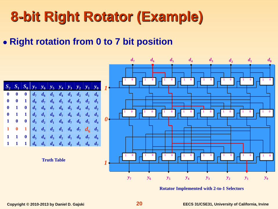
8-bit Right Rotator
Truth Table
S2 S1 S0 y7 y6 y5 y4 y3 y2 y1 y0
0 0 0 d7 d6 d5 d4 d3 d2 d1 d0
0 0 1 d0 d7 d6 d5 d4 d3 d2 d1 0 1 0 d1 d0 d7 d6 d5 d4 d3 d2
0 1 1 d2 d1 d0 d7 d6 d5 d4 d3
1 0 0 d3 d2 d1 d0 d7 d6 d5 d4 1 0 1 d4 d3 d2 d1 d0 d7 d6 d5
1 1 0 d5 d4 d3 d2 d1 d0 d7 d6 1 1 1 d6 d5 d4 d3 d2 d1 d0 d7
Right rotation from 0 to 7 bit position
d0 d3 d1 d2 d4 d7 d5 d6
Rotator Implemented with 2-to-1 Selectors
S2
S1
S0
y0 y3 y1 y2 y4 y7 y5 y6
0 1 0 1 0 1 0 1 0 1 0 1 0 1 0 1
0 1 0 1 0 1 0 1 0 1 0 1 0 1 0 1
0 1 0 1 0 1 0 1 0 1 0 1 0 1 0 1
Copyright © 2010-2013 by Daniel D. Gajski EECS 31/CSE31, University of California, Irvine 20
8-bit Right Rotator (Example)
Truth Table
S2 S1 S0 y7 y6 y5 y4 y3 y2 y1 y0
0 0 0 d7 d6 d5 d4 d3 d2 d1 d0
0 0 1 d0 d7 d6 d5 d4 d3 d2 d1 0 1 0 d1 d0 d7 d6 d5 d4 d3 d2
0 1 1 d2 d1 d0 d7 d6 d5 d4 d3
1 0 0 d3 d2 d1 d0 d7 d6 d5 d4
1 0 1 d4 d3 d2 d1 d0 d7 d6 d5
1 1 0 d5 d4 d3 d2 d1 d0 d7 d6 1 1 1 d6 d5 d4 d3 d2 d1 d0 d7
Right rotation from 0 to 7 bit position d0 d3 d1 d2 d4 d7 d5 d6
Rotator Implemented with 2-to-1 Selectors
1
0
1
y0 y3 y1 y2 y4 y7 y5 y6
0 1 0 1 0 1 0 1 0 1 0 1 0 1 0 1
0 1 0 1 0 1 0 1 0 1 0 1 0 1 0 1
0 1 0 1 0 1 0 1 0 1 0 1 0 1 0 1

Copyright © 2010-2013 by Daniel D. Gajski EECS 31/CSE31, University of California, Irvine 21
1-to-2 Decoder
Boolean Expression Logic Schematic
E A0 C1 C0
1 0 0 1
1 1 1 0
0 X 0 0
Decoders are used for enabling one or more components
C0 = E A′0 C1 = E A0
Truth Table
Graphic Symbol
Decoder
C1 C0
A0
E 0 1
A0 E
C0 C1
Copyright © 2010-2013 by Daniel D. Gajski EECS 31/CSE31, University of California, Irvine 22
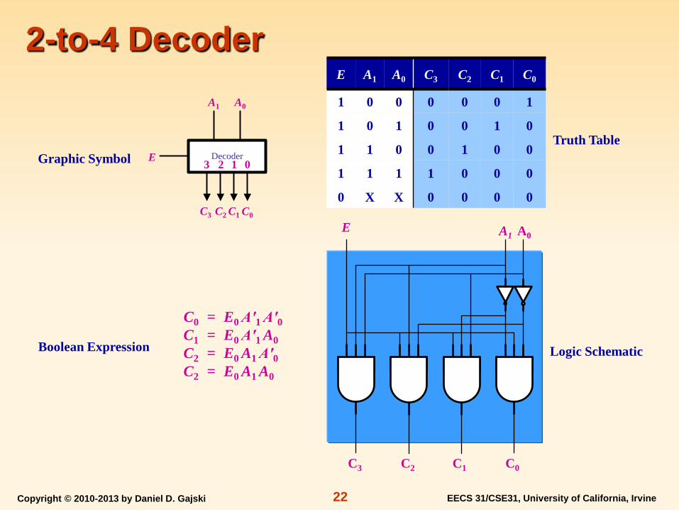
2-to-4 Decoder
Boolean Expression Logic Schematic
E A1 A0 C3 C2 C1 C0
1 0 0 0 0 0 1
1 0 1 0 0 1 0
1 1 0 0 1 0 0
1 1 1 1 0 0 0
0 X X 0 0 0 0
C0 = E0 A′1 A′0 C1 = E0 A′1 A0 C2 = E0 A1 A′0 C2 = E0 A1 A0
Truth Table Graphic Symbol E Decoder
C3 C0
A0
C2 C1
A1
0 3 1 2
A1 E
C1 C2 C0 C3
A0
Copyright © 2010-2013 by Daniel D. Gajski EECS 31/CSE31, University of California, Irvine 23
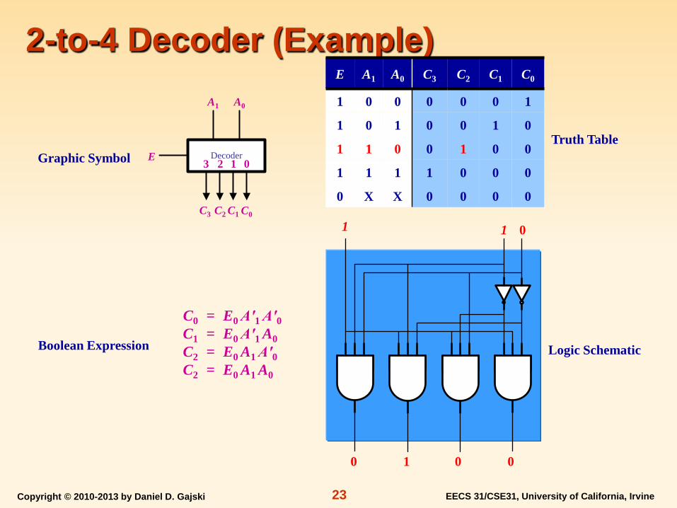
2-to-4 Decoder (Example)
Boolean Expression Logic Schematic
E A1 A0 C3 C2 C1 C0
1 0 0 0 0 0 1
1 0 1 0 0 1 0
1 1 0 0 1 0 0
1 1 1 1 0 0 0
0 X X 0 0 0 0
C0 = E0 A′1 A′0 C1 = E0 A′1 A0 C2 = E0 A1 A′0 C2 = E0 A1 A0
Truth Table Graphic Symbol E Decoder
C3 C0
A0
C2 C1
A1
0 3 1 2
1 1
0 1 0 0
0

Copyright © 2010-2013 by Daniel D. Gajski EECS 31/CSE31, University of California, Irvine 24
3-to-8 Decoder E A2 A1 A0 C7 C6 C5 C4 C3 C2 C1 C0 1 0 0 0 0 0 0 0 0 0 0 1 1 0 0 1 0 0 0 0 0 0 1 0 1 0 1 0 0 0 0 0 0 1 0 0 1 0 1 1 0 0 0 0 1 0 0 0 1 1 0 0 0 0 0 1 0 0 0 0 1 1 0 1 0 0 1 0 0 0 0 0 1 1 1 0 0 1 0 0 0 0 0 0 1 1 1 1 1 0 0 0 0 0 0 0 0 X X X 0 0 0 0 0 0 0 0 Truth Table
Larger decoders can be built as a tree of smaller decoders
Implementation with 2-to-4 Decoders
Decoder
C7 C0
A1
E
A0 A2
…
Graphic Symbol
Implementation with 1-to-2 Decoders C3 C0 C2 C1 C7 C4 C6 C5
E A0 A2 A1
E 0 1
E 0 1
E 0 1
E 0 1
E 0 1
E 0 1
E 0 1
C3 C0 C2 C1 C7 C4 C6 C5
E A0 A2 A1
E 0 1
E 0 3 1 2
E 0 3 1 2

Copyright © 2010-2013 by Daniel D. Gajski EECS 31/CSE31, University of California, Irvine 25
3-to-8 Decoder E A2 A1 A0 C7 C6 C5 C4 C3 C2 C1 C0 1 0 0 0 0 0 0 0 0 0 0 1 1 0 0 1 0 0 0 0 0 0 1 0 1 0 1 0 0 0 0 0 0 1 0 0 1 0 1 1 0 0 0 0 1 0 0 0 1 1 0 0 0 0 0 1 0 0 0 0 1 1 0 1 0 0 1 0 0 0 0 0 1 1 1 0 0 1 0 0 0 0 0 0 1 1 1 1 1 0 0 0 0 0 0 0 0 X X X 0 0 0 0 0 0 0 0 Truth Table
Larger decoders can be built as a tree of smaller decoders
Implementation with 2-to-4 Decoders
Decoder
C7 C0
A1
E
A0 A2
…
Graphic Symbol
Implementation with 1-to-2 Decoders C3 C0 C2 C1 C7 C4 C6 C5
1 1 1 0
E 0 1
E 0 1 E 0 1
E 0 1 E 0 1
E 0 1 E 0 1
C3 C0 C2 C1 C7 C4 C6 C5
1 1 1 0
E 0 1
E 0 3 1 2 E 0 3 1 2

Copyright © 2010-2013 by Daniel D. Gajski EECS 31/CSE31, University of California, Irvine 26
2-to-1 Priority Encoder
Boolean Expression Logic Schematic
Encoder is opposite of decoder, but with priority for MSB
A0 = D1 Any = D0 + D1
Truth Table
Graphic Symbol
D1 D0 A0 Any
0 0 0 0
0 1 0 1
1 X 1 1
Encoder
A0
D0
0 1
D1
Any
D1 D0
Any A0

Copyright © 2010-2013 by Daniel D. Gajski EECS 31/CSE31, University of California, Irvine 27
4-to-2 Priority Encoder
Logic Schematic Truth Table
D3 D2 D1 D0 A1 A0 Any
0 0 0 0 0 0 0
0 0 0 1 0 0 1
0 0 1 X 0 1 1
0 1 X X 1 0 1
1 X X X 1 1 1
Graphic Symbol
Boolean Expression
A0 = D′2D1 + D3 A1 = D2 + D3 Any = D0 + D1 + D2 + D3
Encoder
A1
D0
0 3
D3
2 1
D1 D2
A0 Any
D1
A0
D2 D3 D0
A1 Any
Copyright © 2010-2013 by Daniel D. Gajski EECS 31/CSE31, University of California, Irvine 28
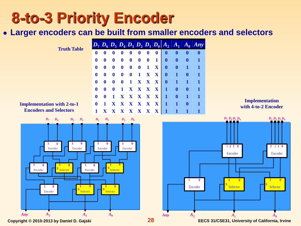
8-to-3 Priority Encoder
Implementation with 2-to-1 Encoders and Selectors
Truth Table
Implementation with 4-to-2 Encoder
D7 D6 D5 D4 D3 D2 D1 D0 A2 A1 A0 Any 0 0 0 0 0 0 0 0 0 0 0 0 0 0 0 0 0 0 0 1 0 0 0 1 0 0 0 0 0 0 1 X 0 0 1 1 0 0 0 0 0 1 X X 0 1 0 1 0 0 0 0 1 X X X 0 1 1 1 0 0 0 1 X X X X 1 0 0 1 0 0 1 X X X X X 1 0 1 1 0 1 X X X X X X 1 1 0 1 1 X X X X X X X 1 1 1 1
Larger encoders can be built from smaller encoders and selectors
D0 D3 D1 D2 D4 D7 D5 D6
A1 A0 Any A2
Encoder Encoder Encoder Encoder
Selector Selector
Selector
EncoderEncoder
Encoder Selector
0 1
0 1 0 1
0 1 0 1 0 1 0 1
0 1 0 1
0 1 0 1
S S
S S
D0 D3 D1 D2
A1 A0 Any A2
D4 D7 D5 D6
Encoder Encoder
SelectorSelectorEncoder
0 1 0 1 0 1 S S
0 3 1 2 0 3 1 2

Copyright © 2010-2013 by Daniel D. Gajski EECS 31/CSE31, University of California, Irvine 29
8-to-3 Priority Encoder
Implementation with 2-to-1 Encoders and Selectors
Truth Table
Implementation with 4-to-2 Encoder
D7 D6 D5 D4 D3 D2 D1 D0 A2 A1 A0 Any 0 0 0 0 0 0 0 0 0 0 0 0 0 0 0 0 0 0 0 1 0 0 0 1 0 0 0 0 0 0 1 X 0 0 1 1 0 0 0 0 0 1 X X 0 1 0 1 0 0 0 0 1 X X X 0 1 1 1 0 0 0 1 X X X X 1 0 0 1 0 0 1 X X X X X 1 0 1 1 0 1 X X X X X X 1 1 0 1 1 X X X X X X X 1 1 1 1
Larger encoders can be built from smaller encoders and selectors
0 0 0 0 0 0 1 0
0 1 1 1
Encoder Encoder Encoder Encoder
Selector Selector
Selector
EncoderEncoder
Encoder Selector
0 1
0 1 0 1
0 1 0 1 0 1 0 1
0 1 0 1
0 1 0 1
S S
S S
0 0 0 0
0 1 1 1
0 0 1 0
Encoder Encoder
SelectorSelectorEncoder
0 1 0 1 0 1 S S
0 3 1 2 0 3 1 2
Copyright © 2010-2013 by Daniel D. Gajski EECS 31/CSE31, University of California, Irvine 30
Combinatorial RTL Summary Described basic combinatorial RTL components: Adders Subtractors Logic Units Decoders Selectors Buses Encoders Comparators Shifters
Presented design for combinatorial components
Discussed procedures for building larger components from smaller ones