RTK BASE STATION...6 RTK Base Station – Installation Examples Now that we have seen and understand...
29
1 RTK BASE STATION: CUSTOMER INSTALLATION AND SETUP GUIDE
Transcript of RTK BASE STATION...6 RTK Base Station – Installation Examples Now that we have seen and understand...

1
RTKBASE STATION:
CUSTOMERINSTALLATION AND
SETUP GUIDE

2
Table of Contents
Section Page
Overview .................................................................................................. 3
Installation Examples............................................................................... 6
Planning ................................................................................................... 9
Setup...................................................................................................... 12
Vehicle Setup......................................................................................... 20
Troubleshooting ..................................................................................... 23
References............................................................................................. 29
3
RTK Base Station Overview
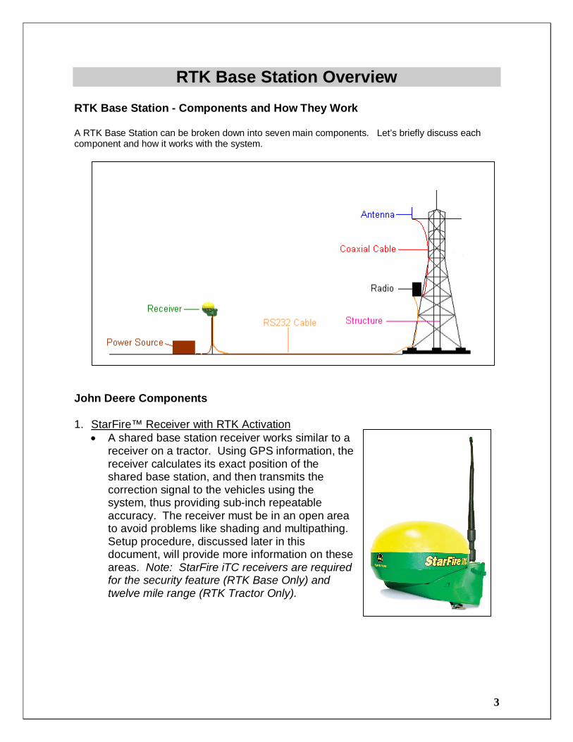
RTK Base Station - Components and How They Work
A RTK Base Station can be broken down into seven main components. Let’s briefly discuss eachcomponent and how it works with the system.
John Deere Components
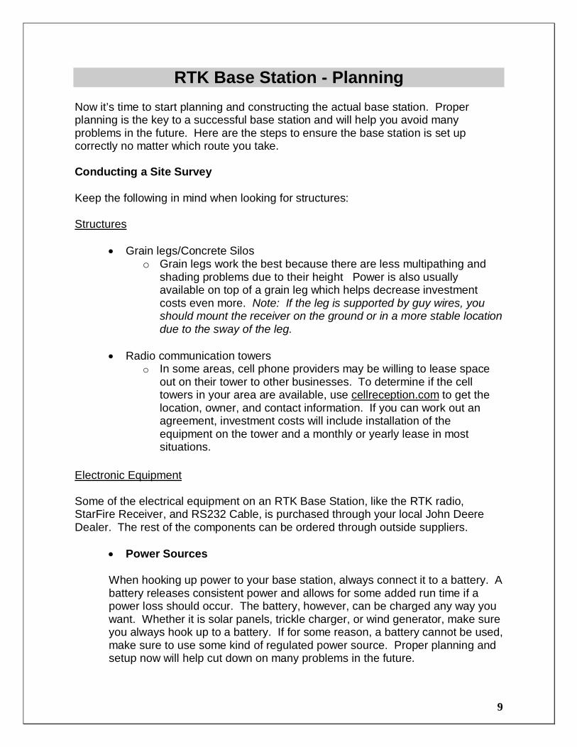
1. StarFire™ Receiver with RTK Activation A shared base station receiver works similar to a
receiver on a tractor. Using GPS information, thereceiver calculates its exact position of theshared base station, and then transmits thecorrection signal to the vehicles using thesystem, thus providing sub-inch repeatableaccuracy. The receiver must be in an open areato avoid problems like shading and multipathing.Setup procedure, discussed later in thisdocument, will provide more information on theseareas. Note: StarFire iTC receivers are requiredfor the security feature (RTK Base Only) andtwelve mile range (RTK Tractor Only).

4
2. RTK Radio The RTK Radio converts the signal from the receiver
into a 900 MHz frequency which is then pushed on tothe antenna. The antenna broadcasts the correctionsignal out to the vehicles running under it. Sub-inchcorrection is only guaranteed out to a twelve mileradius. However, vehicles can still receive signal pastthis distance.
3. RS232 Cable with Ground Rod Static Protection (300 ft.) This cable is used to transmit the correction signal
from the StarFire iTC Receiver to the RTK Radio.This cable is 300 feet long allowing the radio to bemounted on top of a structure while keeping thereceiver closer to the ground for easier maintenanceand updates.
Non John Deere Components
4. Power Source A shared base station requires about three amps of power continuously.
Although the power requirement is small, it needs to be continuous,regulated, and consistent to provide good correction signal to the RTKvehicles using it. Any power surges or losses could disrupt the signal andcause line jumps or loss of signal. No matter what type of power sourcesis used, whether it is solar panels, wind turbines, or a standard 110Vconnection, make sure to hook everything through a battery for cleaner,more consistent power.
5. RF Cable (Low Loss Coaxial) This cable transfers the radio signal from the RTK Radio to the Antenna.
Coaxial cable does lose signal power the greater the distance it istransferred. Make sure you compensate for this loss with a higher gainantenna and high quality low loss coax cable. When constructing yourshared base station, the radio and antenna can be mounted at the top ofthe tower requiring a small coaxial cable or at the bottom of the tower

5
requiring a longer coaxial cable. Remember, the longer the coaxial cable,the bigger it must be to compensate for the signal loss. The size of theantenna does not matter if the signal cannot get there.
Example:i. 100 ft. of LMR 400 Coax Cable has an estimated loss of 3.8 dB
ii. 100 ft. of LMR 600 Coax Cable has an estimated loss of 2.5 dB
6. Antenna The antenna broadcasts the sub-inch correction signal to all of the vehicles
within a 12 mile line of sight radius. Omni-directional antennas arerecommended because they put out equal signal in all directions. Nomatter how you set your SBS RTK Network up, the antenna should bemounted as high as possible to broadcast the correction signal to thevehicles below. All other components, including the RTK radio can bemounted near the ground.
7. Mounting Structure All of the above components are mounted on or near some type of
structure. These structures could be radio/cell towers, water towers, graincooperatives, buildings, or other tall structures. Due to their height, all ofthese options will need to be grounded and have lightning protection toprotect the electronic equipment. Note: If you mount the receiver on thestructure itself, make sure it does not move or sway. This movement willshift all of the Guidance lines under the tower.

6
RTK Base Station – Installation ExamplesNow that we have seen and understand all of the components, let’s move on to thedifferent ways of installing a base station. Depending on the location and structureyou are working with, here are five different methods.
1. Utilizing the 300 ft. RTK Extension Harness
This base station setup allows thereceiver to be mounted in a securelocation while the radio andantenna are mounted together atthe top of the structure. TheRS232 cable between the receiverand radio provides the connectionand power to the rest of thesystem.
Advantage Good receiver placement Not much coax is needed
Disadvantage Generally harder to replace RTK radio if it is struck by lightning
2. Utilizing the Low Loss Coax Cable
This base station setup leaves thereceiver and radio in a securelocation while using low loss coaxcable to connect to the antenna atan elevated position.
Advantage Good receiver location Easy access to the RTK
radio
Disadvantage Increased cost due to coax

7
3. Utilizing Both the 300 Ft. RTK Extension Harness and Low Loss Coax Cable.
This base station setup allowsthe placement of the receiver tobe up to 300 ft. away from theradio, giving the receiver anabsolute clear view of the sky.The radio at the bottom of thetower is then connected to lowloss coax that is ran up the towerto the antenna.
Advantage Good receiver placement Easy access to RTK radio
Disadvantage Increased costs due to
using both the coax and extension harness
4. Utilizing A Repeater
This base station setup allowsthe placement of the receiver andradio in a location with noobstructions. A repeater is placedat an elevated location andbroadcasts the correction signalfrom the base station to thevehicles.
Advantage Good receiver placement
Disadvantage 2 power sources are needed
Repeaters cannot be used anywhere else in the twelve mile range

8
5. Leaving the Radio and Receiver as a Single Unit.
This base station setup keepsthe receiver and radio as asingle unit usually mounted inan elevated location. Importantitems to remember with thisbase station setup are that thereceiver must have a clear viewof the sky, free of multipathing,and cannot move. Anymovement of the receiver willresult in movement of theguidance lines.
Advantage Lower cost
Disadvantages Hard to access the receiver for updates
9
RTK Base Station - PlanningNow it’s time to start planning and constructing the actual base station. Properplanning is the key to a successful base station and will help you avoid manyproblems in the future. Here are the steps to ensure the base station is set upcorrectly no matter which route you take.
Conducting a Site Survey
Keep the following in mind when looking for structures:
Structures
Grain legs/Concrete Siloso Grain legs work the best because there are less multipathing and
shading problems due to their height Power is also usuallyavailable on top of a grain leg which helps decrease investmentcosts even more. Note: If the leg is supported by guy wires, youshould mount the receiver on the ground or in a more stable locationdue to the sway of the leg.
Radio communication towerso In some areas, cell phone providers may be willing to lease space
out on their tower to other businesses. To determine if the celltowers in your area are available, use cellreception.com to get thelocation, owner, and contact information. If you can work out anagreement, investment costs will include installation of theequipment on the tower and a monthly or yearly lease in mostsituations.
Electronic Equipment
Some of the electrical equipment on an RTK Base Station, like the RTK radio,StarFire Receiver, and RS232 Cable, is purchased through your local John DeereDealer. The rest of the components can be ordered through outside suppliers.
Power Sources
When hooking up power to your base station, always connect it to a battery. Abattery releases consistent power and allows for some added run time if apower loss should occur. The battery, however, can be charged any way youwant. Whether it is solar panels, trickle charger, or wind generator, make sureyou always hook up to a battery. If for some reason, a battery cannot be used,make sure to use some kind of regulated power source. Proper planning andsetup now will help cut down on many problems in the future.

10
o 110 Volt connection The best option for your base station power source is a
standard 110 volt power source. To ensure consistentpower, connect the shared base station to a twelve voltbattery, and then recharge the battery with a trickle chargerplugged into the 110 volt power source.
Advantages Disadvantages- Less maintenance - Power losses- Consistent power source(with a battery and tricklecharger)
- Pay a monthly power bill
- If power is lost, the battery willallow for extended run time
Trickle Charger Suppliers – any trickle charger three amps orlarger will work in this situation.
Battery Suppliers – any standard twelve volt battery will workin this type of setup. A deep cycle battery is not necessarybecause the trickle charger will keep the battery charged allthe time.
RTK Radio Boxes
RTK Radios are provided through your local John Deere Dealer.During installation, we recommend putting the radio in aweatherproof lockable box no matter where they are mounted on thestructure. This will not affect their performance, but it will protectagainst tampering and increase the life of the radio. Whatever kindof box you use, make sure there is good air ventilation at thebottom. The radio itself will not give off heat, but the container it isin will build up heat. If a metal box is used, consider painting theoutside a lighter color. These boxes can be found at any localelectrical hardware store.
RF Cable (Coaxial)
The next step is defining the parts neededto maintain signal integrity between theRTK radio and the antenna. If the radio andantenna are mounted in separate areas,low loss coax will have to be used toconnect them. Your local communicationscompany can help you size the right coax

11
and connectors for your structure. Keep the following recommendations inmind:
During rainfall, water can run down the coax and into the RTK Radiodamaging it. To avoid this problem, always leave a drip loop in thecoax for water run off (see picture).
Lightning Protection
o Lightning rods and/or other forms of lightning protection are stronglyrecommended to protect your investment. Lightning protection willincrease the life of your antennas, coax, and RTK radios.
12
RTK Base Station - SetupNow that the RTK Base Station has been constructed, it is now time to set everythingup. The RTK activation must be submitted, the radio must be configured correctly,and an absolute Base Survey must be completed.
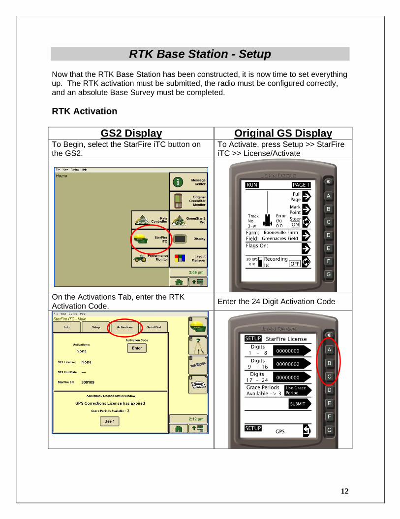
RTK Activation
GS2 Display Original GS DisplayTo Begin, select the StarFire iTC button onthe GS2.
To Activate, press Setup >> StarFireiTC >> License/Activate
On the Activations Tab, enter the RTKActivation Code. Enter the 24 Digit Activation Code
13
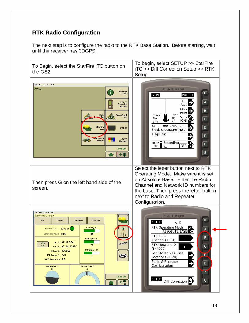
RTK Radio Configuration
The next step is to configure the radio to the RTK Base Station. Before starting, waituntil the receiver has 3DGPS.
To Begin, select the StarFire iTC button onthe GS2.
To begin, select SETUP >> StarFireiTC >> Diff Correction Setup >> RTKSetup
Then press G on the left hand side of thescreen.
Select the letter button next to RTKOperating Mode. Make sure it is seton Absolute Base. Enter the RadioChannel and Network ID numbers forthe base. Then press the letter buttonnext to Radio and RepeaterConfiguration.
14
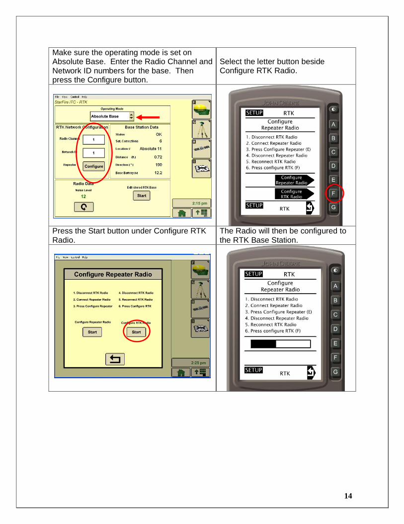
Make sure the operating mode is set onAbsolute Base. Enter the Radio Channel andNetwork ID numbers for the base. Thenpress the Configure button.
Select the letter button besideConfigure RTK Radio.
Press the Start button under Configure RTKRadio.
The Radio will then be configured tothe RTK Base Station.

15
Absolute Base Survey
In the same screen where you justconfigured the radio, push the start button
under Edit Stored RTK base.
To begin, select SETUP>> StarFireiTC >> Diff Correction Setup >> RTKSetup >> Edit Stored RTK BaseLocations
Push the start button under Survey RTKBase Location. This will start the 24 hour
survey.
Press letter button next to SurveyRTK Base Location.

16
Enter the storage location number and thenstart the survey.
Push letter button next to “Survey RTKBase Location.” Then press the letter
button next to “Start Self Survey.”
Recording the Base Station Coordinates
When you record the base station coordinates for the absolute base location, makesure to record the coordinates found under stored base location. Note: It isimportant to manually record the Absolute base surveyed (stored base location)position in a spreadsheet or on paper in a file to retain as a backup in case a basestation fails or is stolen.
RECORD!
17
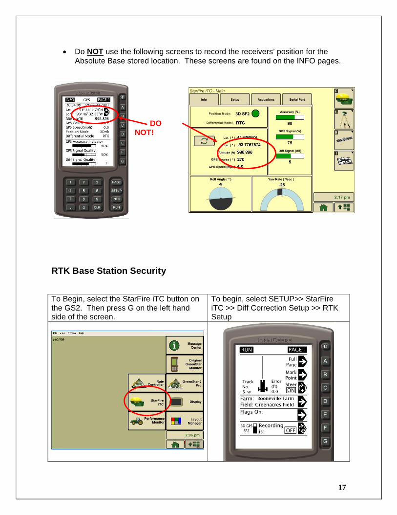
Do NOT use the following screens to record the receivers’ position for theAbsolute Base stored location. These screens are found on the INFO pages.
DONOT!
RTK Base Station Security
To Begin, select the StarFire iTC button onthe GS2. Then press G on the left handside of the screen.
To begin, select SETUP>> StarFireiTC >> Diff Correction Setup >> RTKSetup

18
Make sure the RTK Operating Mode is set toAbsolute Base. Then set the RTK NetworkID to anything from 4001 – 4090. This willcause the security feature to come up belowbutton H on the right hand side of the screen.
Make sure the RTK Operating Modeis set to Absolute Base. Then set theRTK Network ID to anything from4001 – 4090. This will cause thesecurity feature to come up besidebutton F.
Once it is showing, push letter button I on theright hand side of the screen.
Once it is showing, select the letterbutton next to it.

19
Press the Access list button to enter theRover Number and Rover Hardware SerialNumber. Use the toggle switch at thebottom left hand corner to make the networksecure or private.
Now plug in the Rover Number andthe Rover Hardware Serial Number.You can also make the networksecure or public whenever you want.Push letter button E next to ‘RTKNetwork is currently’ to change it.
20
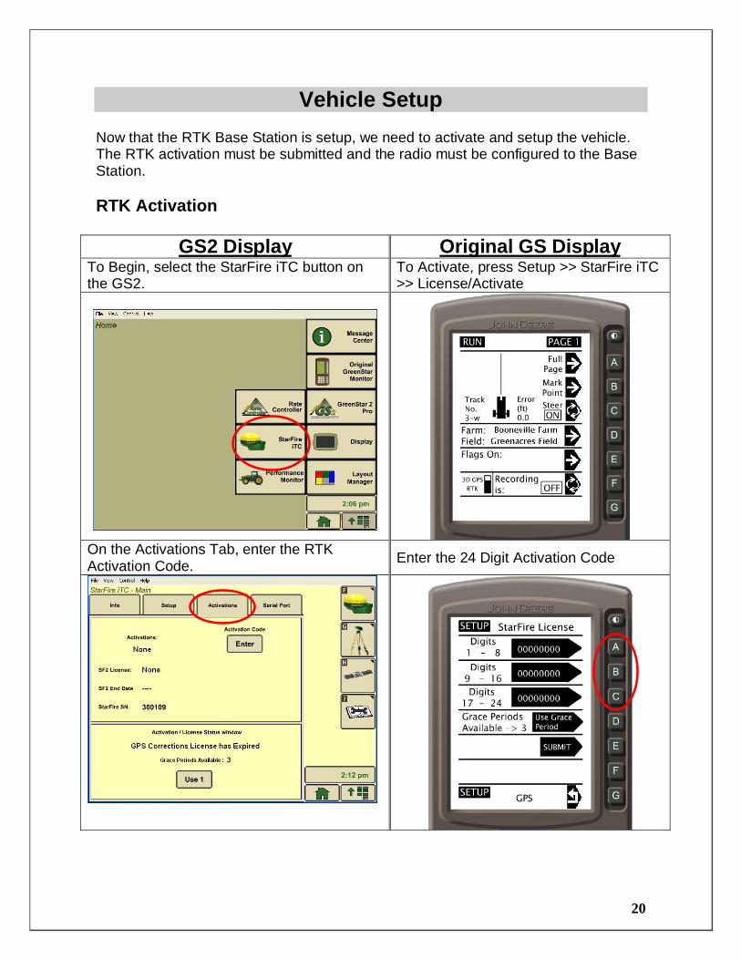
Vehicle SetupNow that the RTK Base Station is setup, we need to activate and setup the vehicle.The RTK activation must be submitted and the radio must be configured to the BaseStation.
RTK Activation
GS2 Display Original GS DisplayTo Begin, select the StarFire iTC button onthe GS2.
To Activate, press Setup >> StarFire iTC>> License/Activate
On the Activations Tab, enter the RTKActivation Code. Enter the 24 Digit Activation Code
21
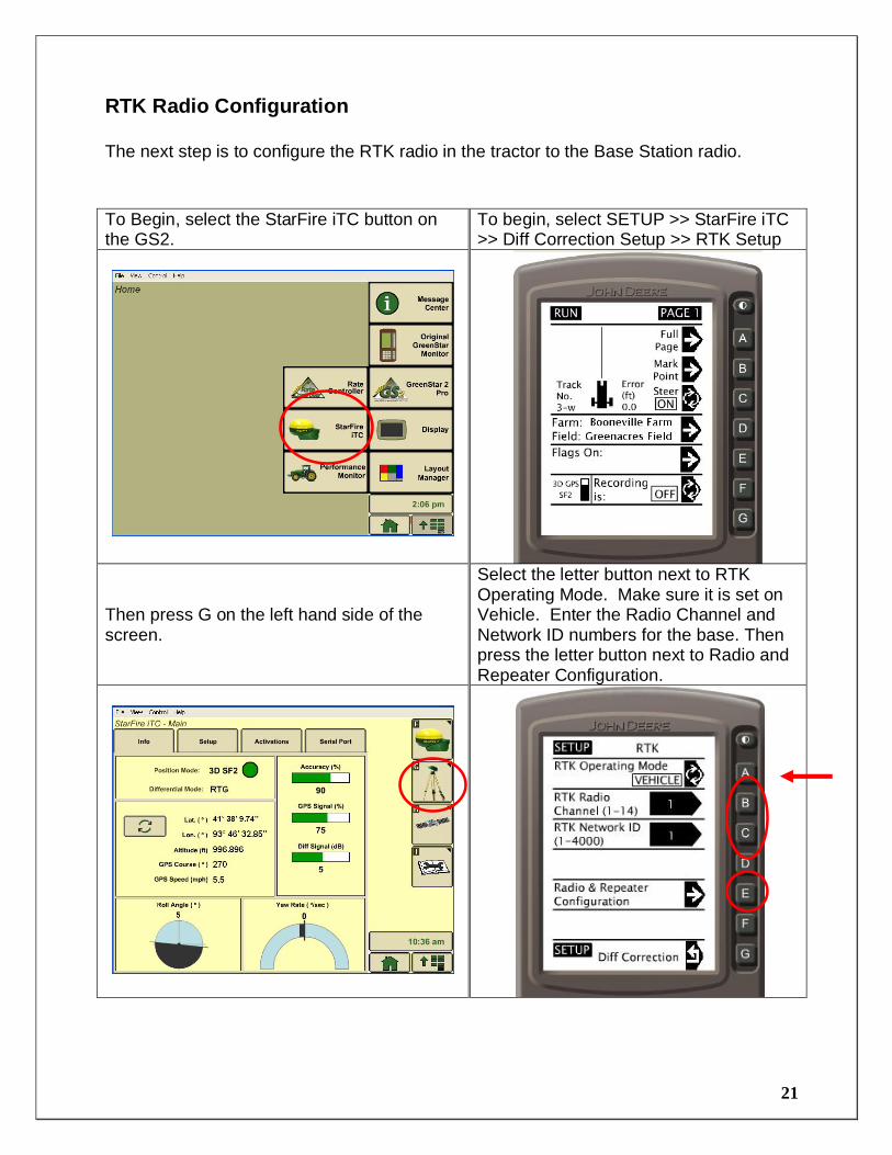
RTK Radio Configuration
The next step is to configure the RTK radio in the tractor to the Base Station radio.
To Begin, select the StarFire iTC button onthe GS2.
To begin, select SETUP >> StarFire iTC>> Diff Correction Setup >> RTK Setup
Then press G on the left hand side of thescreen.
Select the letter button next to RTKOperating Mode. Make sure it is set onVehicle. Enter the Radio Channel andNetwork ID numbers for the base. Thenpress the letter button next to Radio andRepeater Configuration.
22
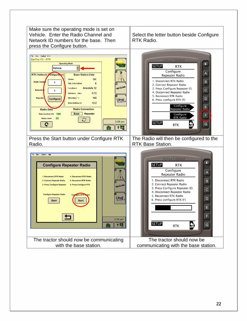
Make sure the operating mode is set onVehicle. Enter the Radio Channel andNetwork ID numbers for the base. Thenpress the Configure button.
Select the letter button beside ConfigureRTK Radio.
Press the Start button under Configure RTKRadio.
The Radio will then be configured to theRTK Base Station.
The tractor should now be communicatingwith the base station.
The tractor should now becommunicating with the base station.
23
TroubleshootingPotential RTK Base Station Problems
Installation and operation of the Base Station Receiver:The receiver is the most critical part of the RTK operation, so setting up a base stationcorrectly is vital to the operation of the RTK system. If the Base Station Receiver is setupin a questionable location, the receiver could have two separate issues; Shading andMultipath.
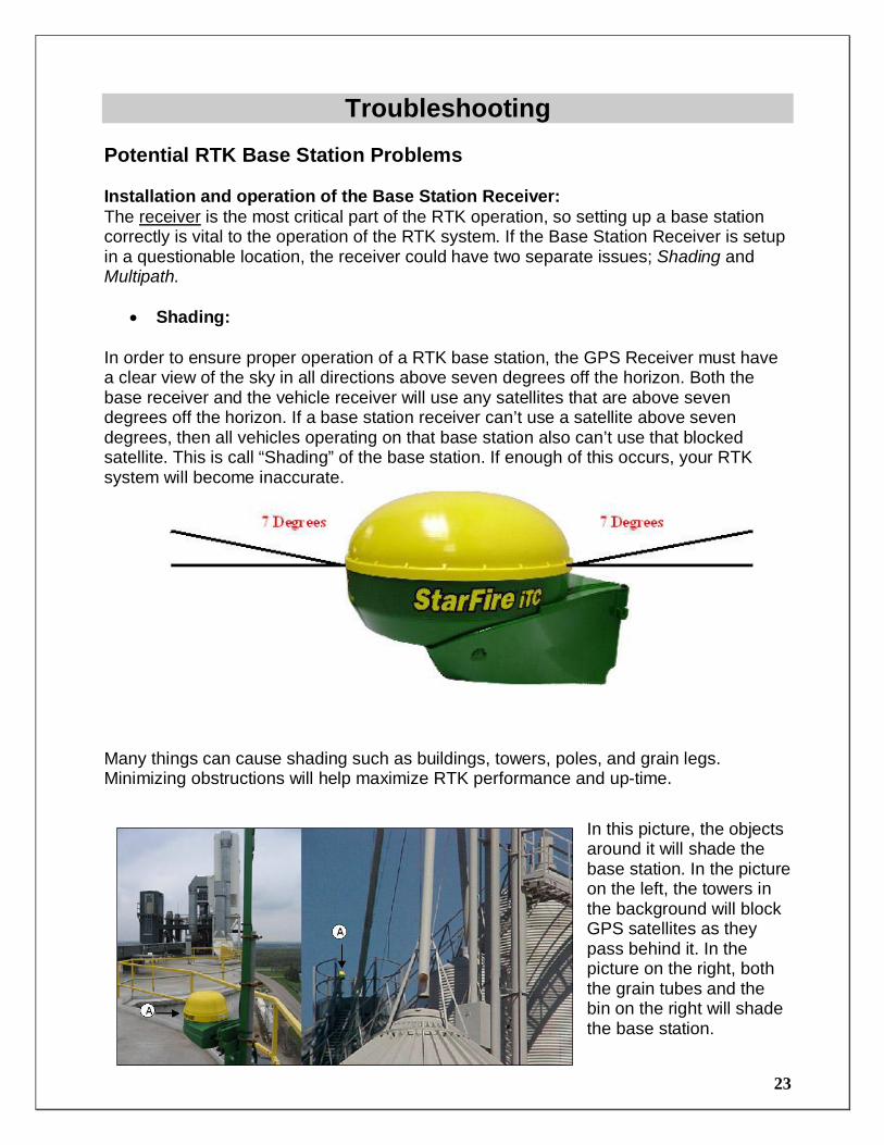
Shading:
In order to ensure proper operation of a RTK base station, the GPS Receiver must havea clear view of the sky in all directions above seven degrees off the horizon. Both thebase receiver and the vehicle receiver will use any satellites that are above sevendegrees off the horizon. If a base station receiver can’t use a satellite above sevendegrees, then all vehicles operating on that base station also can’t use that blockedsatellite. This is call “Shading” of the base station. If enough of this occurs, your RTKsystem will become inaccurate.
Many things can cause shading such as buildings, towers, poles, and grain legs.Minimizing obstructions will help maximize RTK performance and up-time.
In this picture, the objectsaround it will shade thebase station. In the pictureon the left, the towers inthe background will blockGPS satellites as theypass behind it. In thepicture on the right, boththe grain tubes and thebin on the right will shadethe base station.
24
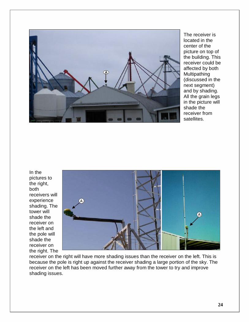
The receiver islocated in thecenter of thepicture on top ofthe building. Thisreceiver could beaffected by bothMultipathing(discussed in thenext segment)and by shading.All the grain legsin the picture willshade thereceiver fromsatellites.
In thepictures tothe right,bothreceivers willexperienceshading. Thetower willshade thereceiver onthe left andthe pole willshade thereceiver onthe right. Thereceiver on the right will have more shading issues than the receiver on the left. This isbecause the pole is right up against the receiver shading a large portion of the sky. Thereceiver on the left has been moved further away from the tower to try and improveshading issues.

25
Multipathing
Before explaining how to protect against Multipathing, let’s discuss exactly what it is:Each satellite sends down time coded messages for any receiver to pick up. If a receiversees multiple time coded messages from the same satellite, it determines there is aproblem with the satellite and discontinues using that satellite until it determines theproblem is corrected. This could take several minutes before the situation corrects itself.The following are some examples of what causes multipath.
Metal roofsCenter pivotsWater towersVehicles parked too closeGrain binsBodies of waterChain link fence
In the pictures below, we have provided illustrations to help show how Multipathingoccurs. The time coded signal from the GPS satellite is being beamed down in alldirections, so if the same time coded signal is reflected off of an object back towards areceiver, the receiver will see the same message many times. If this occurs, you couldsee A/B line jumps while operating in the field. Even though the multipath signal may bereflected in below the 7 degree elevation mask, the receiver doesn’t know it, that isbecause the time coded message tell the receiver that it is actually above seven degrees(i.e. Sat 1; Elev. 35 degrees, Azm 255 degrees) Note: Azimuth is referenced here as anavigation point. True north is considered 0° azimuth. Moving clockwise, a point dueeast would have an azimuth of 90°, south 180°, and west 270°.

26
In the pictures above, both the roof of the car and the building are Multipathing their basestation receiver. The signal is bouncing along the car and building and enter the receivera few milliseconds after the correct GPS message.
In the picture above (left), the base station was being multipathed by the dome of thewater tower. The receiver was one foot off the top of the tower. The customers wouldexperience the following: Two vehicles would be operating at the same time. One vehiclewould go from RTK into RTK-X and see a line jump of up to six inches for a couple ofminutes, while the other vehicle would be operating without incident. At a later time, thesituation would reverse, and the vehicle without incident earlier would go into RTK-X andexperience a line jump, while the other vehicle wouldn’t.
27
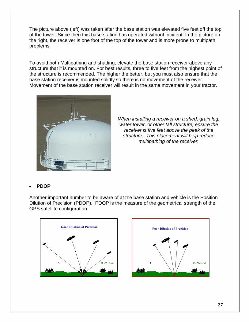
The picture above (left) was taken after the base station was elevated five feet off the topof the tower. Since then this base station has operated without incident. In the picture onthe right, the receiver is one foot of the top of the tower and is more prone to multipathproblems.
To avoid both Multipathing and shading, elevate the base station receiver above anystructure that it is mounted on. For best results, three to five feet from the highest point ofthe structure is recommended. The higher the better, but you must also ensure that thebase station receiver is mounted solidly so there is no movement of the receiver.Movement of the base station receiver will result in the same movement in your tractor.
When installing a receiver on a shed, grain leg,water tower, or other tall structure, ensure the
receiver is five feet above the peak of thestructure. This placement will help reduce
multipathing of the receiver.
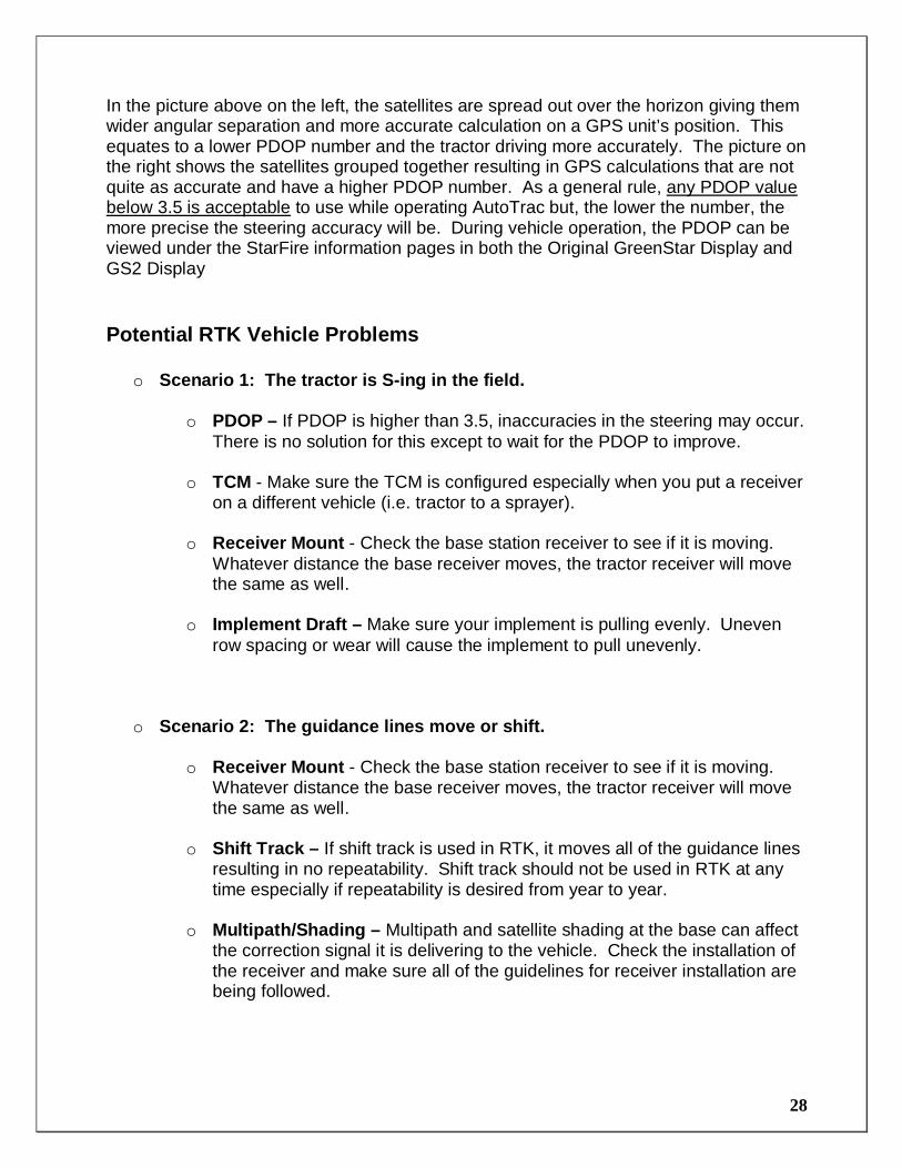
PDOP
Another important number to be aware of at the base station and vehicle is the PositionDilution of Precision (PDOP). PDOP is the measure of the geometrical strength of theGPS satellite configuration.
28
In the picture above on the left, the satellites are spread out over the horizon giving themwider angular separation and more accurate calculation on a GPS unit’s position. Thisequates to a lower PDOP number and the tractor driving more accurately. The picture onthe right shows the satellites grouped together resulting in GPS calculations that are notquite as accurate and have a higher PDOP number. As a general rule, any PDOP valuebelow 3.5 is acceptable to use while operating AutoTrac but, the lower the number, themore precise the steering accuracy will be. During vehicle operation, the PDOP can beviewed under the StarFire information pages in both the Original GreenStar Display andGS2 Display
Potential RTK Vehicle Problems
o Scenario 1: The tractor is S-ing in the field.
o PDOP – If PDOP is higher than 3.5, inaccuracies in the steering may occur.There is no solution for this except to wait for the PDOP to improve.
o TCM - Make sure the TCM is configured especially when you put a receiveron a different vehicle (i.e. tractor to a sprayer).
o Receiver Mount - Check the base station receiver to see if it is moving.Whatever distance the base receiver moves, the tractor receiver will movethe same as well.
o Implement Draft – Make sure your implement is pulling evenly. Unevenrow spacing or wear will cause the implement to pull unevenly.
o Scenario 2: The guidance lines move or shift.
o Receiver Mount - Check the base station receiver to see if it is moving.Whatever distance the base receiver moves, the tractor receiver will movethe same as well.
o Shift Track – If shift track is used in RTK, it moves all of the guidance linesresulting in no repeatability. Shift track should not be used in RTK at anytime especially if repeatability is desired from year to year.
o Multipath/Shading – Multipath and satellite shading at the base can affectthe correction signal it is delivering to the vehicle. Check the installation ofthe receiver and make sure all of the guidelines for receiver installation arebeing followed.

29
o Scenario 3: My tractor will not communicate with the base station.
o Radio configuration – Make sure the correct Network ID and RadioChannel are in the display. If these values are incorrect, the radio will notlock on.
o Antennas – Make sure the antenna is screwed in tightly at the base andthe vehicle. Loose antennas can reduce and even stop the signal beingbroadcasted.
o Base Station – A power loss may have occurred which shut the basestation off.
o Scenario 4: The vehicle is communicating with the base station, but I cannot get 3D RTK.
o Shading – The vehicle must be locked on to satellites before it will go into3D RTK. When you enter a field, make sure to stay away from tree linesuntil the tractor locks on to 3D RTK.
o Radio configuration – The RTK Radio may have not configured correctlythe first time it was setup. Make sure the Network ID and Radio Channelare correct and configure it again.
References1 – 888 - GRNSTAR
Stellar Support Website - http://stellarsupport.deere.com/en_US/
Local John Deere Dealer