
rtc80100brochureCCC - cranered.com pilot operated controls ... matic brake for power up/down mode of...
67
• 100-ton (90 mt) at a 10' (3.05 m) radius • 90,000 lbs. (40 823 kg) travel vehicle weight • 40' to 150' (12.2 - 45.7 m) full-power, five-section formed construction boom, quick-reeve boom head • 31' (9.5 m) one-piece lattice fly, stowable, offsettable to 2°, 25°, and 45° • 31' to 55' (9.5 - 16.8 m) two-piece bi-fold lattice fly, stowable, offsettable to 2°, 25°, and 45° • Two optional 15' (4.6 m) fly extensions increasing fly length to 85' • Maximum tip height of 243' (74.1m) • Three boom modes - A-max1, A-max2 and standard boom lifting capacities • No deducts for stowed attachments • Hydraulic counterweight removal • Hydraulic pinned, removable front and rear outrigger boxes • Removable rear winch with quick disconnects • 21,000 lbs. (9 525 kg) max line pull and 430 fpm (131 mpm) max line speed • Six-wheel hydrostatic drive with fully independent "A" Arm suspensions • Travel speed 18.5 mph (29.8 km/h) • Turning radius of 21' (6.4m) • Ultra-Cab™ with single or dual-axis, pilot operated controls • CabWalk™ Rough Terrain Crane 100-ton (90.72 mt) 80100 RTC SERIES II
Transcript of rtc80100brochureCCC - cranered.com pilot operated controls ... matic brake for power up/down mode of...

• 100-ton (90 mt) at a 10' (3.05 m) radius
• 90,000 lbs. (40 823 kg) travelvehicle weight
• 40' to 150' (12.2 - 45.7 m) full-power,five-section formed construction boom,quick-reeve boom head
• 31' (9.5 m) one-piece lattice fly,stowable, offsettable to 2°, 25°, and 45°
• 31' to 55' (9.5 - 16.8 m) two-piecebi-fold lattice fly, stowable, offsettableto 2°, 25°, and 45°
• Two optional 15' (4.6 m) flyextensions increasing fly length to 85'
• Maximum tip height of 243' (74.1m)
• Three boom modes - A-max1, A-max2and standard boom lifting capacities
• No deducts for stowed attachments
• Hydraulic counterweight removal
• Hydraulic pinned, removablefront and rear outrigger boxes
• Removable rear winch withquick disconnects
• 21,000 lbs. (9 525 kg) maxline pull and 430 fpm (131 mpm)max line speed
• Six-wheel hydrostatic drive withfully independent "A" Armsuspensions
• Travel speed 18.5 mph (29.8 km/h)
• Turning radius of 21' (6.4m)
• Ultra-Cab™ with single ordual-axis, pilot operated controls
• CabWalk™
Rough Terrain Crane100-ton (90.72 mt)
80100RTC
SERIES II

The industry’s most innovativesolution to big rough terraincrane maneuverability andtransportability!
• Revolutionary hydrostatic driveon a three-axle, six-wheeledcarrier for the ultimate injob site mobility
• Breakthrough transportability
• Maneuverability redefined
• 45-ton pick & carry capacities
• New U-shaped, formed boommeets greater length andstability requirements
Rough Terrain Crane100-ton (90.72 mt)
Three position outrigger beams extendto 22' 6" and retract to 9' 7" with use ofhand-held outrigger controls
Independent front Coordinated six wheel drive Six wheel "crab"Independent rear
Unveiling the next generationof formed boom designThis new boom design not only delivers full power boom and tele-
scoping load capability but also delivers a superior load chart anda maximum tip height of 243-ft. (69.49 m) with full attach-
ment. This formed boom is designed for larger cranes tomeet greater length and stability requirements. The
U-shaped, formed construction boom design offersexceptional strength and stability throughout
the crane's chart. Strategically placed wearpads are utilized throughout the
boom to disperse the load to max-imize the overall stability pro-
viding greater capacitiesat longer load radii.
Flat deck design and non-slipsurface strips on deck
Complete lighting package
Fast "hook-and-go" front &rear outrigger beams
Repositionable ladders onfront and back 23.5R25 radial tires
Stowable pontoons
Optional two-piece bi-fold lattice fly can beextended with two optional 15' (4.57 m) flyextensions for up to 85' of fly
80100RTC
SERIES II

Revolutionary hydrostatic drive ona three-axle carrier designNot only is the RTC-80100 Series II easy to get from jobsite to jobsite, it also has extraordi-nary creep control and jobsite maneuverability, thanks to its hydrostatic powered motors ineach wheel. With the smaller tires giving it an overall height of 12' 2.5" (3.72 m), along withits' individual six-wheel hydrostatic drive, there is no crane in the world, any size, that cancome close to the job site maneuverability and performance of the RTC-80100. On the job,the RTC-80100's outstanding pick and carry capacity coupled with its long reach, maneuver-ability, incredible gradeability and low height make it truly an ideal solution for industrial sites.
Partial counterweight andno counterweight charts
Catwalks on bothsides of upper
Because of the innovative 6x6x6 hydrostatic drive/steeron each wheel, the turning radius of the 30' 10" (9.4 m)
long carrier is a remarkable 21' (6.4 m).

Braden winch packagewith available line pullof 21,000 lbs
Standard load hoistsystem consists of amain winch with two-speed motor and auto-matic brake for powerup/down mode ofoperation.
Bi-directional hydraulicmotor, driven througha planetary reductionunit provides precisesmooth load controlwith minimal rpm’s.
Asynchronous, paralleldouble-over grooveddrums minimize ropeharmonic motion,improving spooling andincreasing rope servicelife. A two-speed auxil-iary winch is an avail-able option.
Deflector rollers preventpremature wire ropewear when working atlow boom angles.
Swing-out doors provide exceptional accessto engine components.
Access is superb with strategically-locatedladders, steps, catwalks and CabWalk.
Operator cab features• Extra large front window almost
seamlessly merges into the roof window• Sliding left side door, right and rear
windows, and swing up top window provide excellent ventilation
• All gauges, switches, indicators,and controls are placed in the operator’s forward line of sight for excellent ergonomics
• All gauges and switches are backlit forexcellent visibility when the cab workinglights are switched to the on position
• Integral rated capacity limiter aidsoperator in safe and efficient operation by continuously monitoring boom length,boom angle, head height, radius of load,machine configuration, allowed load, andpercent of allowed load.
• Available – Integrated air conditioningutilizes the same ventilation outlets as thestandard heating system
Õ
Õ
Õ

Amax2Amax1 Standard
New innovative 5-sectionfull power boom withattachment flexibility Wear shoes all the way around
the circumference of the boomspreads the load out and givesyou good capacity and extendedwear shoe life.
Lightweight nylon head sheaves (includingthe optional auxiliary lifting sheave shown
here) reduce overall machine weightand increase lift capacities.
Quick reeve boom head allowsrope to be easily reeved over
boom head.
Hammerhead boom noseallows the operator to work
at high boom angles.
Type “RB” wirerope is standard
Í
A-max modesThe exclusive A-max modes offer substantially increased capacities forin-close, maximum capacity picks, and provide the operator the capabilityto match the crane’s configuration to specific job site conditions.
A-max1 - 95' (29 m): Inner and center sections are extended, offeringmaximum strengthA-max2 - 122' 6" (37.34 m): Tip, outer and center sections are extendedyielding maximum stability The basic boom extension self-proportions allfour sections equally.
Introducing a newboom design,Link-Belt is unveilingthe next generationformed boom designfor larger cranes tomeet greater lengthand stability requirements. TheU-shaped, formed construction boomdesign offers exceptional strength andstability throughout the crane's chart.Strategically placed wear pads are utilizedthroughout the boom to disperse the load tomaximize the overall boom strength and stabilityproviding greater capacities at longer load radii. • 150' (45.72 m)• Maximum tip height is 243' (74.1 m)
with the full attachment and main boomused in combination
• Can telescope loads of greater capacity than power-pinned booms• No deducts for stowed attachments
Optional lattice fly attachments• 31' (9.44 m) one-piece lattice fly with lugs
to allow addition of second section• 31' - 55' (9.44 - 16.76 m)• Also available are optional 15' (4.57 m)
fly extensions that extend the bi-foldattachment to 70' with one section and85' using two sections
• Erection of two-piece (bi-fold) lattice flyis a one-man operation
• Exclusive design reduces side deflectionwhen lifting load
• Easy to erect and stow• Attachments offset to 2°, 25° and 45°

Breakthroughtransportability• Unlike any other rough terrain crane in this class,
in less than an hour, without a helper crane, theRTC-80100 is stripped to less than 90,000 lbs. andis ready for transport.
• Unlike other big RT's, the tires do not need to beremoved for transport.
• Only the counterweights and outrigger boxes needto be removed to get the crane's vehicle width under10' (3.05 m).
• Because it is under 10-ft wide and features a low12' 2.5" (3.72 m) overall height, the RTC-80100Series II incurs no daytime or weekend travelrestrictions unlikecompetitor's craneswhich exceed widthand weight restrictions,which require specialpermits.
• The crane ships in twoloads. Using an 18"conventional, dropdeck trailer the craneunit is easily loadedout. The second truckhandles the counter-weights, fly extensionsand outrigger boxes.
Link-Belt ConstructionEquipment Company isa leader in the design,manufacture and sales oftelescopic and lattice boomcranes, with headquarters inLexington, Kentucky.
In the recent decade, a dynamic and highlyfocused Link-Belt has emerged as a marketleader in crane design and product qualitystandards by focusing on continuousimprovement and employee empowerment.
Link-Belt operates on the principles ofcontinuous quality improvement, ISO 9001,and established values that support thevision of quality. These principles result inreduction in waste, better use of companyresources and improved employee andcustomer satisfaction.
With major capital improvements overthe last ten years, along with continuousimprovement philosophies, this facility hasemerged as the most modern crane facilityin North America.
Lexington, Kentuckywww.linkbelt.com
® Link-Belt is a registered trademark. Copyright 2006.All rights reserved. We are constantly improving ourproducts and therefore reserve the right to changedesigns and specifications.
Litho in U.S.A. 8/07 #4336 (supersedes #4325)

Litho in U.S.A. 3/03 #5378 (Supersedes #5357)
������������Telescopic Boom Rough Terrain Crane
RTC–80100 100–ton (90.72 metric ton)���������
L
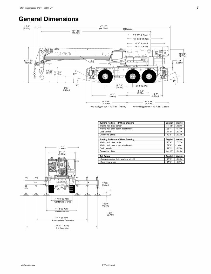
28”(0.71 m)
7’ 7.38” (2.32 m)
11’ 2” (3.40 m)
18’ 7” (5.66 m)
26’ 0” (7.93 m)
13.75”(0.35 m)
Turning Radius (6–wheel steer –centerline of tires 20’ 7” 6.27Turning Radius (2–wheel steer –centerline of tires 35’ 10.67Turning Radius (6–wheel steer – outside front outrigger box 25’ 6” 7.77Turning Radius (2–wheel steer – outside front outrigger box 37’ 0” 11.28Tailswing of counterweight (w/o Aux. Winch) 13’ 9” 3.90Tailswing of Auxiliary Winch 15’ 3” 4.65
General Dimensions feet metric
Full Retraction
Intermediate Extension
Centerline of tires
Full Extension
47’ 10”(14.58 m)
40’ 1.63”(12.23 m)
12’ 11.63”(3.95 m)
7’ 1.88”(2.18 m)
5’ 10.5”(1.79 m)
2’ 5”(0.73 m)
27�
15�
15’ 4.88”(4.70 m)
13’ 0”(3.96 m)
15’ 4.88”(4.70 m)
13’ 0”(3.96 m)
8’ 0.5”(2.45 m)
8’ 0.5”(2.45 m)
15�
27�
2’ 0” (0.61 m)
12’ 2.5”(3.71 m)
8’ 6.56” (2.61 m)
9’ 11”(3.02 m)
12’ 0”(3.65 m)
17.75”(0.45 m)
10.29”(0.26 m)
w/o outrigger box – 12’ 4.88” (3.68 m)w/o outrigger box – 12’ 4.88” (3.68 m)
C Rotation
RTC–80100
Link–Belt
13’ 3.38” (4.05 m)
13’ 9” (4.19 m)
15’ 2” (4.62 m)

� �RTC–80100 Series II
Upper Structure� BoomFormed Construction Design� U–shaped boom utilizes formed plates to
resist buckling using high strength 130,000p.s.i. (896 MPa) steel. Increased wear padarea for improved load distribution and longerlife.
Standard Boom� 40’ – 150’ (12.19 – 45.72 m) five–section full
power boom.� Standard mode is the full power, synchro-
nized mode of telescoping all sections pro-portionally.
� A–max1 mode (or mode ‘A1’) extends onlythe inner and center sections to 95’ (29 m)offering increased capacities for in–close,maximum capacity picks.
� A–max2 mode (or mode ‘A2’) tip, outer andcenter sections extend to 122.5’ (37.34 m)offering maximum stability.
� Mechanical Boom Angle Indicator
Boom Head� �����16.38” (0.42 m) root diameter nylon
sheaves handle up to twelve parts of wire rope.� Quick–reeve design� Rope dead end lugs provided on each side of
boom head� Easily removable wire rope guards� Fly pinning alignment tool
Boom Elevation� One Link–Belt designed hydraulic cylinder with
holding valve and bushings in each end.� Hand control for controlling boom
elevation from –3� to 80�.
Optional Auxiliary Lifting Sheave� Single 16.38” (0.42 m) root diameter nylon
sheave with removable wire rope guard.� Use with one or two parts of line.� Does not affect erection of fly or use of main
head sheaves for multiple reeving.
Optional� 100–ton (90.72 mt) 6–sheave, quick reeve
hook block, with safety latch� 80–ton (72.57 mt) 5–sheave, quick reeve
hook block with safety latch� 50–ton (45.36 mt) 4–sheave, quick reeve
hook block with safety latch� 12–ton (10.89 mt) hook ball (swivel) with
safey latch� Boom floodlight
� FlyOptional� 31’ – 55’ (9.45 – 16.76 m) two–piece (bifold)
stowable, offsettable to 2�, 25� or 45�.� Two, 15’ (4.57 m) fly extensions provide a
total fly length of 85’ (25.9 m).
� Cab and ControlsEnvironmental ULTRA CAB�
� LCF–2000 construction process featuringlaminated fibrous composite material.
� Isolated from sound with acoustical vinyl in-sulation.
� Six–way adjustable operator’s seat with re-tractable seat belt.
� Four–way adjustable tilting–telescoping andlocking steering wheel.
� All windows are tinted and tempered safety glass.
� Slide by door opens to 3’ (0.91 m) width.� Sliding rear and right side windows and swing
up roof window for maximum visibility andventilation.
� Engine dependent warm–water heater withdefroster.
� Audible swing alarm � Warning horn� Backup alarm � Travel lights� 12–volt accessory outlet � Sun screen� Electric windshield wiper � Mirrors� Top hatch window wiper � Cup holder� Fire extinguisher � Circulating fan� Windshield washer
Optional� Amber strobe light� Amber rotating beacon� Air conditioning
ControlsHydraulic controls (joystick type) for:� Front winch � Boom hoist� Optional rear winch � Swing� Drum rotation indicators� Single–axis controls – optional� Hand–held outrigger controls and sight level
bubble also provided in upper cab.
Foot controls for:� Boom telescope � Swing brake� Engine throttle with throttle lock� Service brake
Cab InstrumentationCorner–post mounted gauges with integralaudio/visual warning system for:� Tachometer � Voltmeter� Oil pressure � Fuel� Hydraulic oil temperature� Water temperature
� Rated Capacity Limiter� Microguard 434 Graphic audio–visual warn-
ing system built into the cornerpost with anti–two block and function limiters.
� Anti–two block weight designed for quickreeve of hookblock.
Operating data available includes:� Machine configuration � Actual load� Boom length � Boom angle� Head height � Radius of load� % of allowed load � Allowed load
Presettable alarms include:� Maximum and minimum boom angles.� Maximum tip height.� Maximum boom length.� Swing left/right positions.� Operator defined area alarm is standard.
Optional� Internal RCL light bar: Visually informs op-
erator when crane is approaching maximumload capacity (kickouts and presettablealarms) with a series of green, yellow and redlights.
� External RCL light bar: Visually informsground crew when crane is approachingmaximum load capacity (kickouts and preset-table alarms) with a series of three lights;green, yellow and red.
� Swing� Bi–directional hydraulic swing motor mounted to
a planetary reducer for 360� continuous smoothswing at 1.5 r.p.m.
� Swing park brake – 360� electric over hy-draulic (spring applied, hydraulic released)multi–disc brake mounted on the speed re-ducer. Operated by switch in lefthand control-ler.
� Swing brake – 360�, foot operated, hydraulic applied disc brake mounted on thespeed reducer.
� Swing lock – Standard; two position travellock operated from the operator’s cab.
� 360� pawl–in–gear swing lock – meetsNew York City requirements. – (optional)
� Counterweight� Standard – 24,000 lbs. (10 886 kg). Capaci-
ties for 0 (0 kg) and 12,000 lbs (5 443 kg)also available.
� Optional����ydraulic counterweight removalcontrolled with hand–held controller from theground.
� Hydraulic SystemMain Pumps� A Two–section gear pump, mounted to a me-
chanical pump drive, driven by the diesel en-gine supplies hydraulic power for the boomhoist, telescope, and charge circuits. Sectionone can deliver 47 gpm at 4,400 psi and sec-tion two can deliver 38 gpm at 4,400 psi.
� Two, closed–loop piston pumps are mountedto a mechanical pump drive, driven by thediesel engine and serve as travel pumps.These two pumps supply hydraulic power tothe wheel motors and are capable of deliver-ing 88 gpm at 6,090 psi each.
� Two closed loop piston pumps are mountedto the rear of the two travel pumps. The leftpump drives the front winch and the rightpump drives the optional rear winch. eachpump is capable of delivering 49 gpm at4,150 psi.
� A pressure compensated piston pumpmounted to the rear of the left winch pumpsupplies hydraulic power to the outrigger,counterweight removal (optional), oscillation,and travel brake circuits/ This pump can de-liver 21 gpm at 3,000 psi.
� A single section gear pump mounted to therear of the right side winch pump supplieshydraulic power to the swing and steeringcircuits. This pump can deliver 27 gpm at3,000 psi.
� O–Ring Face Seal (ORFS) technologythroughout with hydraulic oil cooler.
Reservoir� �� gal. (965 L) capacity. Diffuser for deaera-
tion.
Filtration:� One 7–micron filter located inside
hydraulic reservoir.� Accessible for easy replacement.� One 7–micron charge filter located next to the
reservoir with an in–cab indicator light
Control Valves:� Five separate, pilot operated control valves
allow simultaneous operation of all cranefunctions.

–3– RTC–80100 Series II
� All control valves are pressure compensatedfor improved metering.
� Adjustable fine metering control on winch,boom hoist and swing functions.
� Load Hoist SystemStandard� 2M front winch with grooved lagging.� Two–speed motor and automatic brake.� Power up/down mode of operation.� Controls for future addition of rear winch.
� Bi–directional, piston–type hydraulic motor,driven through a planetary reduction unit forpositive operator control under all load condi-tions.
� Asynchronous parallel double crossovergrooved drums minimize rope harmonic motion.
� Rotation resistant wire rope.
Line Pulls and Speeds� Maximum line pull 21,022 lbs. (9 535 kg) and
maximum line speed of 431 f.p.m. (131.40m/min) on standard 15” (0.38 m) root diame-ter grooved drum.
Optional� 2M rear winch with two–speed motor,
automatic brake, grooved lagging and powerup/down mode of operation.
� Hoist drum cable followers.� Third wrap indicators.
Carrier� Type� 9’ 11” (3.02 m) wide, 156.75” (4.19 m) wheel-
base.� 6 x 6 x 6 – (6–wheel steer, 6–wheel drive)
For rough terrain with limited turning area.
Frame� 100,000 p.s.i. (689.5 MPa) steel, torsion re-
sistant, single–box construction.� Integral 100,000 p.s.i. (689.5 MPa) steel out-
rigger boxes.
Standard Carrier Equipment� One front, one rear, and two mid–point
carrier ladders� Non–slip safety strips on carrier deck� Full deck fenders� Pontoon storage� Full lighting package� Front towing shackles� Hook block tie back� Carrier mounted mirrors
Optional� Front and rear mounted pintle hook� Hydraulic power pinning outrigger boxes
� EngineEngine Detroit Diesel
Series 40Cylinders – cycleBoreStrokeDisplacementMaximum brake hpPeak torque (ft. lb.)Electric systemStarting systemFuel capacityAlternatorCrankcase capacity(total system)
6 – 44.59 in. (116.59 mm)5.35 in. (135.89 mm)530 cu. in. (8.69 L)300 @ 2,000 rpm1,050 @ 1,300 rpm12 volt12 volt95 gallons (360 L)130 amps28 qts. (26.5 L)
� Water/fuel separator on engine� 110–volt block heater� Optional – Ether injection package
� Transmission� �������������������������������������
��������������������������������������������������������������������������������������������������������������������������
� Axles� Six, heavy–duty Link–Belt fabricated axle
housings that support the wheel drive motorsand connect to the steering and suspensionsystem.
� Suspension� Fully independent double “A” Arm construc-
tion with automatic axle oscillation
� Steering� Hydraulic front–wheel, rear–wheel, coordi-
nated six–wheel and six–wheel “crab” steer-ing
� Modes selected by rotary switch on overheadconsole.
� All modes are fully coordinated and controlledby steering wheel.
Optional� Rear steer indicator
� TiresFront and Rear� Standard 23.5R25 2–Star radials.
Optional� Spare tires and rims
� BrakesService� Two, fully hydraulic caliper disc–type brakes
at each wheel end with independent front andrear system. Controlled by foot pedal in cab.
Parking/Emergency� Spring applied, hydraulic released, cab con-
trolled, wet, multiple disc–type integral to thefront wheel drive motors.
� Outriggers� Three position operation capability.� Four hydraulic, telescoping beam and jack
outriggers.� Vertical jack cylinders equipped with
integral holding valve.� Beams extend to 26’ (7.93 m) centerline–to–
centerline and retract to a 12’ (3.6 m) width.� Equipped with stowable, lightweight 26” (0.66
m) round steel pontoons.� Hand–held controls and sight level bubble
located in upper structure cab.
Confined Area Lifting Capacities(CALC�) System� Three operational outrigger configurations are
available:� Full extension – 26’ (7.93 m)� Intermediate position – 18’ 7” (5.66 m)� Full retraction – 11’ 2” (3.22 m)
� For confined area operation, rated lifting ca-pacities are provided for the intermediate andfully retracted outrigger positions.
� When the outrigger position levers (located on the outrigger beams) are engaged, the operator can set the crane inthe intermediate or full retraction outriggerposition without leaving the cab.
� Travel Speeds and Gradability
With outrigger boxes and counterweight
Tires 23.5R25 2–Star radials
Maximum Speed 18.5 (29.77 km/h)
Gradability at 1.0mph (1.6 km/hr)
50.4%
Maximum TractiveEffort at 1.0 mph.(1.6 km/hr)
61,180 lbs. (27 751 kg)
Without outrigger boxes and counterweight
Tires 23.5R25 2–Star radials
Maximum Speed 18.5 (29.77 km/h)
Gradability at 1.0mph (1.6 km/hr)
88%
Maximum TractiveEffort at 1.0 mph.(1.6 km/hr)
61,180 lbs. (27 751 kg)
� Travel Load
Tire Max. Axle Load @ 20mph (32.20 km/hr)
23.5R25 2–Star 57,330 lbs. (26 005 kg)

���RTC–80100 Series II
� Axle LoadsBase machine with standard 40 – 150’(12.19 – 45.72 m) five–section boom,
�
Upper facing front Upper facing rear
2M main winch with 2–speed hoistingand power up/down, 850’ (259 m) of7/8” (22 mm) wire rope. 6x6x6 carrier
G.V.W.�Front axle Rear axle group Front axle Rear axle group
7/8” (22 mm) wire rope. 6x6x6 carrierwith Detroit Diesel Series 40 engine,23.5R25 tires, 95 gals. (360 L) of fuel, lbs. kg. lbs. kg. lbs. kg. lbs. kg. lbs. kg.tow shackles, hook block tieback and24,000 lbs. (10 886 kg) of counter-weight. 123,666 56 094 38,355 17 398 85,311 38 696 55,045 24 968 68,621 31 126
Remove outrigger boxes and beams –15,960 –7 239 –6,035 –2 737 –9,925 –4 502 –6,035 –2 737 –9,925 –4 502Remove main counterweight –24,182 –10 969 12,928 5 864 –37,110 –16 833 –31,518 –14,296 7,336 3 328
Cold weather start aid – ether injector 19 9.5 –2 –0.9 21 10 –2 –0.9 8 4Pintle hook, front 20 9 29 13 –9 –4 29 13 –9 –4
Pintle hook, rear 20 9 –9 –4 29 13 –9 –4 29 13Rear steer indicator 10 4.5 –2 –1 12 5 –2 –1 12 5
Winch roller – rear winch 110 50 –82 –37 192 87 166 75 –56 –25Winch roller – front winch 94 42 –42 –4 141 64 119 54 –25 –11
2M Auxiliary Winch 1,700 771 –1,143 –518 284 1,289 2,449 1 110 –749 –348500’ (152 m) of 7/8” (22 mm) wire ropeon auxiliary winch 862 391 –579 –263 1,441 518 1,242 563 –380 –172
Air conditioning in operator’s cab 120 54 48 22 72 33 44 20 76 34360 degree swing lock 139 63 35 16 104 47 71 32 68 31
Fly brackets to boom base sectionsfor fly options 277 126 372 169 –95 –43 –159 –72 436 198
31’ – 55’ (9.45 – 16.76 m) offset fly(stowed) 2,632 1 194 4,223 1 916 –1,591 –722 –2,200 –998 4,832 2 192
Floodlight to boom base section 10 5 26 12 –16 –7 –18 –8 28 13100–ton (90.72 mt) capacity hookblock to front/rear bumper 1,750 794 2,537 1 151 –787 –357 –1,192 –541 2,942 1 334
80–ton (72.57 mt) capacity hook blockto front/rear bumper 1,411 640 2,046 928 –635 –288 –961 –436 2,372 1 076
50–ton (45.36 mt) capacity hook blockto front/rear bumper 1,200 544 1,740 789 –540 –244 –817 –370 2,017 915
12–ton (10.9 mt) capacity hook ball tofront/rear bumper 722 327 1,047 475 –325 –147 –492 –223 1,214 551
Auxiliary lifting sheave 120 54 347 157 –227 –103 –254 –115 374 170
� – Adjust gross weight and axle loading according to component weight. Note: All weights are � 3%.
C
BTotal Weight: 88,257 lbs. (40 033 kg), equipped with:� 40’ – 150’, Five–Section Boom� 80–ton Hookblock� One winch with 850’ of 7/8” rope� 31’ – 55’ Bi–fold fly� Ether injection system� Hot water cab heater� Air Conditioning� Tow Shackles� Pintle Hooks
Drop Off Load Weight: 41,642 lbs. (18 889 kg)� Two outrigger boxes� 24,000 lbs (10 886 kg) Counterweight� Two, 15’ (4.57 m) Fly Sections
Axle Group Weights
Truck Wt. Bed Length Steer Drivers Trailer A45,200 lbs. 24’ 10,055 lbs. 57,606 lbs. 65,734 lbs. 10.5”(20 502 kg) (7.32 m) (4 561 kg) (26 129 kg) (29 816 kg) (0.27 m)
54,200 lbs. 34’ 10,090 lbs. 58,864 lbs. 73,503 lbs. 50.5”(24 585 kg) (10.36 m) (4 577 kg) (26 700 kg) (33 340 kg) (1.28 m)
B – 18” (0.46 m) or 24” (0.61 m)
Normal Suspension Collapsed SuspensionC (with 18” Trailer) 13’ 8” (4.17 m) 13’ 5” (4.09 m)C (with 24” Trailer) 14’ 2” (4.32 m) 13’ 11” (4.24 m)
ARTC–80100 Series II TransportConfiguration and Weights
Link–Belt Construction Equipment Company Lexington, Kentucky www.linkbelt.com�Link–Belt is a registered trademark. Copyright 2003. All rights reserved. We are constantly improving our products and therefore reserve the right to change designs and specifications.

15494 (supersedes 5471)---0906---J7
RTC---80100 IILink-Belt Cranes
Technical DataSpecifications & Capacities
Telescopic Boom Rough Terrain Crane100 ton (90.72 metric ton)
CAUTION: This material is supplied forreference use only. Operator must refer toin---cab Crane RatingManual andOperator’sManual to determine allowable crane liftingcapacities and assembly and operatingprocedures.

5494 (supersedes 5471)---0906--- J7
RTC---80100 II Link-Belt Cranes

5494 (supersedes 5471)---0906--- J7
RTC---80100 IILink-Belt Cranes
Table Of ContentsBoom, Attachments, and Upper Structure 1. . . . . . . . . . . . . . . . . . . . . . . . . . . . . . . . . . . . . . . . . . . . . . . . . . . .Boom 1. . . . . . . . . . . . . . . . . . . . . . . . . . . . . . . . . . . . . . . . . . . . . . . . . . . . . . . . . . . . . . . . . . . . . . . . . . . . . . . . . . . .Boom Head 1. . . . . . . . . . . . . . . . . . . . . . . . . . . . . . . . . . . . . . . . . . . . . . . . . . . . . . . . . . . . . . . . . . . . . . . . . . . . .Boom Elevation 1. . . . . . . . . . . . . . . . . . . . . . . . . . . . . . . . . . . . . . . . . . . . . . . . . . . . . . . . . . . . . . . . . . . . . . . . . .Auxiliary Lifting Sheave --- Optional 1. . . . . . . . . . . . . . . . . . . . . . . . . . . . . . . . . . . . . . . . . . . . . . . . . . . . . . . . .Hook Blocks and Balls --- Optional 1. . . . . . . . . . . . . . . . . . . . . . . . . . . . . . . . . . . . . . . . . . . . . . . . . . . . . . . . . .Fly --- Optional 1. . . . . . . . . . . . . . . . . . . . . . . . . . . . . . . . . . . . . . . . . . . . . . . . . . . . . . . . . . . . . . . . . . . . . . . . . . .Fly Extensions --- Optional 1. . . . . . . . . . . . . . . . . . . . . . . . . . . . . . . . . . . . . . . . . . . . . . . . . . . . . . . . . . . . . . . . .Operator’s Cab and Controls 1. . . . . . . . . . . . . . . . . . . . . . . . . . . . . . . . . . . . . . . . . . . . . . . . . . . . . . . . . . . . . . . .Swing 2. . . . . . . . . . . . . . . . . . . . . . . . . . . . . . . . . . . . . . . . . . . . . . . . . . . . . . . . . . . . . . . . . . . . . . . . . . . . . . . . . . . .Electrical 2. . . . . . . . . . . . . . . . . . . . . . . . . . . . . . . . . . . . . . . . . . . . . . . . . . . . . . . . . . . . . . . . . . . . . . . . . . . . . . . . .Load Hoist System 3. . . . . . . . . . . . . . . . . . . . . . . . . . . . . . . . . . . . . . . . . . . . . . . . . . . . . . . . . . . . . . . . . . . . . . . . .Load Hoist Performance 3. . . . . . . . . . . . . . . . . . . . . . . . . . . . . . . . . . . . . . . . . . . . . . . . . . . . . . . . . . . . . . . . . . .2M Main and Optional Auxiliary Winches 3. . . . . . . . . . . . . . . . . . . . . . . . . . . . . . . . . . . . . . . . . . . . . . . . . . . .Engine 3. . . . . . . . . . . . . . . . . . . . . . . . . . . . . . . . . . . . . . . . . . . . . . . . . . . . . . . . . . . . . . . . . . . . . . . . . . . . . . . . . . .Drive System 4. . . . . . . . . . . . . . . . . . . . . . . . . . . . . . . . . . . . . . . . . . . . . . . . . . . . . . . . . . . . . . . . . . . . . . . . . . . . . .Fuel Tank 4. . . . . . . . . . . . . . . . . . . . . . . . . . . . . . . . . . . . . . . . . . . . . . . . . . . . . . . . . . . . . . . . . . . . . . . . . . . . . . . . .Hydraulic System 4. . . . . . . . . . . . . . . . . . . . . . . . . . . . . . . . . . . . . . . . . . . . . . . . . . . . . . . . . . . . . . . . . . . . . . . . . .Pump Drive 4. . . . . . . . . . . . . . . . . . . . . . . . . . . . . . . . . . . . . . . . . . . . . . . . . . . . . . . . . . . . . . . . . . . . . . . . . . . . . . .Counterweight 4. . . . . . . . . . . . . . . . . . . . . . . . . . . . . . . . . . . . . . . . . . . . . . . . . . . . . . . . . . . . . . . . . . . . . . . . . . . .Carrier 5. . . . . . . . . . . . . . . . . . . . . . . . . . . . . . . . . . . . . . . . . . . . . . . . . . . . . . . . . . . . . . . . . . . . . . . . . . . . . . . . . . . .General 5. . . . . . . . . . . . . . . . . . . . . . . . . . . . . . . . . . . . . . . . . . . . . . . . . . . . . . . . . . . . . . . . . . . . . . . . . . . . . . . . . . .Outriggers 5. . . . . . . . . . . . . . . . . . . . . . . . . . . . . . . . . . . . . . . . . . . . . . . . . . . . . . . . . . . . . . . . . . . . . . . . . . . . . . . .Steering and Wheel Drive Motors 5. . . . . . . . . . . . . . . . . . . . . . . . . . . . . . . . . . . . . . . . . . . . . . . . . . . . . . . . . . . .Suspension 5. . . . . . . . . . . . . . . . . . . . . . . . . . . . . . . . . . . . . . . . . . . . . . . . . . . . . . . . . . . . . . . . . . . . . . . . . . . . . . .Tires and Wheels 5. . . . . . . . . . . . . . . . . . . . . . . . . . . . . . . . . . . . . . . . . . . . . . . . . . . . . . . . . . . . . . . . . . . . . . . . . .Brakes 5. . . . . . . . . . . . . . . . . . . . . . . . . . . . . . . . . . . . . . . . . . . . . . . . . . . . . . . . . . . . . . . . . . . . . . . . . . . . . . . . . . .Electrical 5. . . . . . . . . . . . . . . . . . . . . . . . . . . . . . . . . . . . . . . . . . . . . . . . . . . . . . . . . . . . . . . . . . . . . . . . . . . . . . . . .Carrier Speeds and Gradeability 5. . . . . . . . . . . . . . . . . . . . . . . . . . . . . . . . . . . . . . . . . . . . . . . . . . . . . . . . . . . . .Hydraulic System 5. . . . . . . . . . . . . . . . . . . . . . . . . . . . . . . . . . . . . . . . . . . . . . . . . . . . . . . . . . . . . . . . . . . . . . . . . .Axle Loads 6. . . . . . . . . . . . . . . . . . . . . . . . . . . . . . . . . . . . . . . . . . . . . . . . . . . . . . . . . . . . . . . . . . . . . . . . . . . . . . . .Transport Configuration and Weights 6. . . . . . . . . . . . . . . . . . . . . . . . . . . . . . . . . . . . . . . . . . . . . . . . . . . . . . . .General Dimensions 7. . . . . . . . . . . . . . . . . . . . . . . . . . . . . . . . . . . . . . . . . . . . . . . . . . . . . . . . . . . . . . . . . . . . . . . .Working Range Diagram 8. . . . . . . . . . . . . . . . . . . . . . . . . . . . . . . . . . . . . . . . . . . . . . . . . . . . . . . . . . . . . . . . . . . .Boom Extend Modes 9. . . . . . . . . . . . . . . . . . . . . . . . . . . . . . . . . . . . . . . . . . . . . . . . . . . . . . . . . . . . . . . . . . . . . . .Main Boom Lift Capacity Charts -- Standard 10. . . . . . . . . . . . . . . . . . . . . . . . . . . . . . . . . . . . . . . . . . . . . . . . .24,000 lb Counterweight --- Fully Extended Outriggers --- 360˚ Rotation 10. . . . . . . . . . . . . . . . . . . . . . . . . . .24,000 lb Counterweight --- On Tires --- Stationary --- Boom Centered Over Rear Between Tire Tracks 1224,000 lb Counterweight --- On Tires --- Pick & Carry (Creep) --- Boom Centered Over Rear 13. . . . . . . . .24,000 lb Counterweight --- On Tires --- Stationary --- 360˚ Rotation 13. . . . . . . . . . . . . . . . . . . . . . . . . . . . . .

5494 (supersedes 5471)---0906--- J7
RTC---80100 II Link-Belt Cranes
Fly Attachment Lift Capacity Charts -- Optional 14. . . . . . . . . . . . . . . . . . . . . . . . . . . . . . . . . . . . . . . . . . . . . . .24,000 lb Counterweight --- Fully Extended Outriggers --- 360˚ Rotation 14. . . . . . . . . . . . . . . . . . . . . . . . . . .150 ft Main Boom Length --- 2˚ Fly Offset 14. . . . . . . . . . . . . . . . . . . . . . . . . . . . . . . . . . . . . . . . . . . . . . . . . . . .150 ft Main Boom Length --- 25˚ Fly Offset 15. . . . . . . . . . . . . . . . . . . . . . . . . . . . . . . . . . . . . . . . . . . . . . . . . . .150 ft Main Boom Length --- 45˚ Fly Offset 16. . . . . . . . . . . . . . . . . . . . . . . . . . . . . . . . . . . . . . . . . . . . . . . . . . .
Main Boom Lift Capacity Charts -- Optional (Metric) 17. . . . . . . . . . . . . . . . . . . . . . . . . . . . . . . . . . . . . . . . . .10 885kg Counterweight --- Fully Extended Outriggers --- 360˚ Rotation 17. . . . . . . . . . . . . . . . . . . . . . . . . .10 885kg Counterweight --- On Tires --- Stationary --- Boom Centered Over Rear Between Tire Tracks 1910 885kg Counterweight --- On Tires --- Pick & Carry (Creep) --- Boom Centered Over Rear 20. . . . . . . . .10 885kg Counterweight --- On Tires --- Stationary --- 360˚ Rotation 20. . . . . . . . . . . . . . . . . . . . . . . . . . . . . .Fly Attachment Lift Capacity Charts -- Optional (Metric) 21. . . . . . . . . . . . . . . . . . . . . . . . . . . . . . . . . . . . . . .10 885kg Counterweight --- Fully Extended Outriggers --- 360˚ Rotation 21. . . . . . . . . . . . . . . . . . . . . . . . . .45.72m Main Boom Length --- 2˚ Fly Offset 21. . . . . . . . . . . . . . . . . . . . . . . . . . . . . . . . . . . . . . . . . . . . . . . . . .45.72m Main Boom Length --- 25˚ Fly Offset 22. . . . . . . . . . . . . . . . . . . . . . . . . . . . . . . . . . . . . . . . . . . . . . . . .45.72m Main Boom Length --- 45˚ Fly Offset 23. . . . . . . . . . . . . . . . . . . . . . . . . . . . . . . . . . . . . . . . . . . . . . . . .

15494 (supersedes 5471)---0906--- J7
RTC---80100 IILink-Belt Cranes
Boom, Attachments, and Upper StructureJ BoomDesign --- Five section, formed construction of extra hightensile steel consisting of one base section and four tele-scoping sections. The first telescoping section extendsindependently by means of one, double---acting, singlestage hydraulic cylinder with integral holding valves. Thesecond telescoping section extends independently bymeans of one, double---acting, single stage hydraulic cylin-der with integral holding valves. The third and fourth sec-tions extend proportionally by means of one, double---act-ing, single stage cylinder with integrated holding valvesand cables.
BoomS 40---150 ft (12.2 ---45.7m) five section full power boomS Three boom extend modes, controlled from the opera-tor’s cab, provide superior capacities by varying the ex-tension of the telescoping sections:S Standard mode is the full power, synchronized modeof telescoping all sections proportionally
S A---max1mode (or mode ‘A1’) extends only the innerand center sections to 95 ft (29m) offering increasedcapacities for in---close, maximum capacity picks
S A---max2mode (or mode ‘A2’) tip, outer and center sec-tions extend to 122.5 ft (37.34m) offering maximumstability
S Mechanical boom angle indicatorS Maximum tip height for each extend mode is:S Standard is 159 ft 6 in (48.6m).S A---max2 is 132 ft 6 in (40.3m)S A---max1 is 105 ft 6 in (32.1m)Boom Wear PadsS Bottom wear pads are universal for all boom sectionsS Top wear pads are universal for all boom sectionsBoom HeadS Six 16.5 in (41.9cm) root diameter nylon sheaves to han-dle up to twelve parts of line
S Easily removable wire rope guardsS Rope dead end lugs on each side of the boom headS Boom head is designed for quick---reeve of the hookblockBoom ElevationS One double acting hydraulic cylinder with integral hold-ing valve
S Boom elevation: ---3˚ to 80˚Auxiliary Lifting Sheave --- OptionalS Single 16.5 in (41.9m) root diameter nylon sheaveS Easily removable wire rope guardsS Does not affect erection of the fly or use of the main headsheaves
Hook Blocks and Balls --- OptionalS 100 ton (90.72mt) 6 sheave, quick---reeve hook block, withsafety latch
S 80 ton (72.57mt) 5 sheave, quick---reeve hook block withsafety latch
S 50 ton (45.36mt) 4 sheave, quick---reeve hook block withsafety latch
S 12 ton (10.89mt) hook ball (swivel) with safety latchFly --- OptionalS 31 ft---55 ft (9.45---16.76m) two piece bi---fold lattice fly,stowable, offsettable to 2˚, 25˚, and 45˚. Maximum tipheight for 31 ft (9.45m) fly is 190 ft (57.9m) and for the 55 ft(16.76m) is 214 ft (65.2m).Fly Extensions --- OptionalS One 15 ft (4.57m) lattice extension to be mounted be-tween the 31 ft (9.45m) and 55 ft (16.76m) fly options.Maximum tip height is 228 ft 6 in (69.65m).
S Two 15 ft (4.57m) lattice extensions to be mounted be-tween the 31 ft (9.45m) and 55 ft (16.76m) fly options.Maximum tip height is 243 ft (74.07m).
J Operator’s Cab and ControlsEnvironmental Cab --- Fully enclosed, one person cab ofgalvaneal steel structure with acoustical insulationEquipped with:S Tinted and tempered glass windowsS Extra---large fixed front window with windshield wiper andwasher
S Swing up roof window with windshield wiperS Sliding left side door with large fixed windowS Sliding rear and right side windows for ventilationS Six way adjustable, cushioned seat with seat belt andstorage compartment
S Engine dependent warm---water heater with air ducts forfront windshield defroster and cab floor
S Defroster fan for the front windowS Bubble levelS Circulating fanS Adjustable sun visorS Dome lightS Cup holderS Fire extinguisherS Left side viewing mirrorS Two position travel swing lockAir Conditioning --- Optional --- Integral with cab heatingsystem utilizing the same ventilation outletsSteering Column --- Pedestal type with tilt and telescopefunctions for operator comfort. Column includes the follow-ing controls and indicators:Left and right levers include:
S Horn buttonS Turn signal switchS Driving light switchS Forward/Neutral/Reverse direction switch

2 5494 (supersedes 5471)---0906--- J7
RTC---80100 II Link-Belt Cranes
Panel mounted switches for:S Travel park brakeS Steer mode selectorS 2/6 wheel drive/range selectorS Hazard flasherPanel mounted indicator/warning lights for:
S Travel circuit temperatureS Engine oil pressureS Travel park brakeS Service brakeS Turn signalsS Case filter restrictionS Charge filter restrictionS Pump CPU errorS Engine overspeedS Rear wheel offset---optionalS Emergency steer --- optionalArmrest Controls --- Two dual axis hydraulic joystick con-trollers or optional single axis hydraulic controllers for:S SwingS Boom hoistS Main rear winchS Auxiliary front winch --- optionalS Drum rotation indicationS Drum rotation indicator activation switchS Winch high/low speed and disable switch(es)S Third wrap selector switch --- optionalS Telescopic override switchesS Warning horn buttonS Swing park brakeOutrigger Controls --- Hand held control box with umbilicalcord gives the operator the freedom to view operation whilesetting the outriggers.Foot ControlsS Boom telescopeS Swing brakeS Engine throttleS Service brakeRight Front Console --- Controls and indicators for:S Engine ignition S Console dimmer switchS Engine throttle lock S Bubble levelS Function disable S 12 volt power connectionS Fine metering S Air conditioning --- optionalS Front windshield wiper S Boom floodlight --- optionaland washer S Rotating beacon/Strobe
S Cab floodlights light --- optionalS Warning horn S Third wrap indicator ---S Heating controls optionalCab Instrumentation --- Ergonomically positioned, analoginstrumentation for crane operation including:S Engine coolant temperature with warning indicatorS Hydraulic oil temperature with warning indicatorS Fuel level with warning indicatorS TachometerS Travel circuit temperature with warning indicatorS Voltmeter with warning indicator
Rated Capacity Limiter --- Microguard graphic audio---visual warning system integrated into the dash with anti ---two block and function limiter. Operating data availableincludes:S Crane configurationS Boom length and angleS Boom head heightS Allowed load and % of allowed loadS Boom angleS Radius of loadS Actual loadS Operator settable alarms (include):S Maximum and minimum boom anglesS Maximum tip heightS Maximum boom lengthS Swing left/right positionsS Operator defined area (imaginary plane)
S Two 15 ft (4.57m) lattice extension to be mounted be-tween the 31 ft (9.45m) and 55 ft (16.76m) fly options.Maximum tip height is 243 ft (74.07m).Internal RCL Light Bar --- Optional --- Visually informs theoperator when crane is approaching maximum load capac-ity with a series of green, yellow, and red lights.External RCL Light Bar --- Optional --- Visually informs theground crew when crane is approaching maximum loadcapacity with a series of green, yellow, and red lights.
J SwingMotor/Planetary --- Bi ---directional hydraulic swing motormounted to a planetary reducer for 360˚ continuoussmooth swing at 1.5 rpm.Swing Park Brake --- 360˚, electric over hydraulic, (springapplied/hydraulic released) multi ---disc brake mounted onthe speed reducer. Operated by a toggle switch from theoperator’s cab.Swing Brake --- 360˚, foot operated, hydraulic applied discbrake mounted to the speed reducer.Swing Lock --- Two---position swing lock (boom over frontor rear) operated from the operator’s cab.360˚ Positive Swing Lock --- Optional --- Meets New YorkCity requirement.
J ElectricalSwing Alarm --- Audio warning device signals when theupper is swinging.LightsS Two working lights on front of the cabS One rotating amber beacon on top of the cab --- optionalS One amber strobe beacon on top of the cab --- optionalS Boom floodlight --- optional

35494 (supersedes 5471)---0906--- J7
RTC---80100 IILink-Belt Cranes
J Load Hoist SystemLoad Hoist Performance
Front and Rear Winches --- 7/8 in (22mm) RopeMaximum Line Pull Normal Line Speed High Line Speed Layer Total
Layer lb kg ft/min m/min ft/min m/min ft m ft m1 21,022 9 535.4 141 43.0 279 85.0 125 38.1 125 38.12 18,986 8 611.9 156 47.5 310 94.5 138 42.0 263 80.23 17,820 8 083.0 172 52.4 340 103.6 152 46.3 415 126.54 15,868 7 197.6 187 57.0 370 112.8 165 50.3 588 179.25 14,669 6 653.7 202 61.6 400 121.9 179 54.6 759 231.36 13,639 6 186.5 217 66.1 431 131.4 192 58.5 951 289.9
Wire Rope ApplicationDiameter
TypeMaximum
Permissible Loadin mm lb kg
Rear WinchStandard 7/8 22 18x19 rotation resistant --- right regular lay (Type RB) 17,520 7 946.9Optional 7/8 22 36x7 rotation resistant --- right regular lay (Type ZB) 20,920 9 489.2
Front WinchStandard 7/8 22 18x19 rotation resistant --- right regular lay (Type RB) 17,520 7 946.9Optional 7/8 22 36x7 rotation resistant --- right regular lay (Type ZB) 20,920 9 489.2
2M Main and Optional Auxiliary WinchesS Axial piston, full and half displacement (2---speed) motorsdriven through planetary reduction unit for positive con-trol under all load conditions.
S Grooved laggingS Power up/down mode of operationS Hoist drum cable followerS Drum rotation indicatorS Drum diameter: 15 in (38.1cm)S Rope length:S Front: 850 ft (215.9m)S Rear: 500 ft (127.0m)
S Maximum rope storage: 951 ft (289.9m)S Terminator style socket and wedgeThird wrap indicator --- optional --- Visually and audiblywarns the operator when the wire rope is on the first (bot-tom) layer and when the wire rope is down to the last threewraps.
J EngineSpecification Detroit Diesel Series 40
Numbers of Cylinders 6
Cycle 4
Bore and Stroke: inch (mm) 4.59 x 5.35 (116.59 x 135.89)
Piston Displacement: in3 (L) 530 (8.69)
Max. Brake Horsepower: hp (kW) 330 (246) @ 2,000 rpm
Peak Torque: ft lb (Nm) 1,050 (1 424) @ 1,300 rpm
Electric/starting systems: volts 12/12
Alternator: amps 130
Crankcase Capacity: qt (L) 28 (26.5)
S Water/fuel separator on engineS 110---volt block heaterS Ether injection --- optional

4 5494 (supersedes 5471)---0906--- J7
RTC---80100 II Link-Belt Cranes
J Drive SystemHydrostatic type consisting of two variable speed pistonpumps supplying hydraulic power to six hydraulic cam lobewheel drive motors computer controlled for smooth andreliable operation.
J Fuel TankOne 95 gal (359.6L) capacity tank
J Hydraulic SystemAll functions are hydraulically powered allowing positiveprecise control with independent or simultaneous operationof all functions.Main PumpsS One, two section gear pump for the boom hoist, tele-scope, and charge circuits.
S Two, closed---loop piston pumps serve as travel pumps.these two pumps supply hydraulic power to the wheelmotors.
S Two, closed---loop piston pumps are mounted to the rearof the two travel pumps. The left pump drives the frontwinch and the right pump drives the optional rear winch.
S One, pressure compensated piston pump mounted tothe rear of the left winch pump supplies hydraulic powerto the outrigger, counterweight removal (optional), oscilla-tion, and travel brake circuits.
S One, single section gear pump mounted to the rear of theright side winch pump supplies hydraulic power to theswing and steering circuits.
Hydraulic Reservoir --- 255 gal (96.5L) capacity equippedwith sight level gauge. Diffuser built in for deaeration. Mag-netic drain plug and large internal magnetFiltrationS One, 7---micron filter located inside hydraulic reservoir,accessible for easy replacement
S One, 7---micron charge filter located next to the reservoirwith an in---cab indicator light
S Two, 10---micron pressure filters located next to the reser-voir with change indicators
S Three, 100 mesh suction strainers located inside the hy-draulic reservoirCounterbalance Valves --- All boom extend cylinders andboom hoist cylinder are equipped with counterbalancevalves to provide load lowering and prevents accidentalload drop when hydraulic power is suddenly reduced.
J Pump DriveAll pumps are mounted on the pump drive gearbox andmechanically driven by the diesel engine.
J CounterweightTotal of 24,000 lb (10 886kg) consisting of two removablecounterweights pinned to the upper with capacities for 0 lb(0kg), 12,000 lb (5 443kg), and 24,000 lb (10 886kg) config-urations.S Optional --- Hydraulic counterweight removal activated bya hand---held controller with enough cable to access thepins on each side of the counterweights.

55494 (supersedes 5471)---0906--- J7
RTC---80100 IILink-Belt Cranes
CarrierJ GeneralS 9 ft 11 in (3.02m) wideS 16 ft 1 in (4.90m) wheelbase (centerline of first axle tocenterline of third axle).Frame --- Box---type, torsion resistant, welded constructionmade of high tensile steel. Equipped with front and reartowing and tie---down lugs, tow connections, and accessladders.
J OutriggersBoxes --- Two removable, double box, front and rearpinned to carrier frame. Hydraulic outrigger pin removal ---optional.Beams and Jacks --- Four single stage beams with Con-fined Area Lifting Capacities (CALCt) provide selectableoutrigger extensions of full, intermediate, and retracted.Hydraulically controlled from the operator’s cab with inte-gral check valves.Pontoons --- Four lightweight, quick release, 26 in (0.66m)diameter, steel pontoons with contact area of 539 in2(3 477cm2) can be stored for road travel in storage rackson the carrier.Main Jack Reaction --- 132,000 lb (59 874kg) force and245 psi (1 689kPa) ground bearing pressure.
J Steering and Wheel Drive MotorsSteering --- Four independent modes consisting of twowheel front, four wheel rear, six wheel, and crab. Eachmode is controlled from the steering wheel and is selectedby a switch in the operator’s cab.Drive --- Three modes: 6 x 2 high, 6 x 2 low, and 6 x 6 foroff highway travelFront Drive Motors --- Steered, driven for 6 x 2 and 6 x 6Rear Drive Motors --- Steered, non---driven for 6 x 2 andsteered, driven for 6 x 6
J SuspensionFront --- Double “A” arms connected to oscillation cylindersthat lockout when the upper structure rotates 3˚ past cent-erlineLeft Rear --- Center and rear wheels mounted on double“A” arms connected to oscillation cylinders that lockoutwhen the upper structure rotates 3˚ past centerline. Os-cillation occurs across left center and left rear wheels.Right Rear --- Center and rear wheels mounted on double“A” arms connected to oscillation cylinders that lockoutwhen the upper structure rotates 3˚ past centerline. Os-cillation occurs across right center and right rear wheels.Ride Height Adjustment --- Suspension can be lowered fortransport using a hand---held controller from the ground.
J Tires and WheelsFront and Rear --- Six (single) 23.5 x 25---2 star radials,earthmover type tires on steel disc wheelsS Spare tires and wheels --- optional
J BrakesService --- Full hydraulic, dual circuit, disc type brakes onall wheel endsParking/Emergency --- Spring loaded type, acting on frontwheel ends
J ElectricalThree batteries provide 12 volt operation and startingLightsS Front lighting includes two main headlights and two park-ing/directional indicators
S Side lighting includes two parking/directional indicatorsper side
S Rear lighting includes two parking/directional indicators,two parking/brake lights, and two reversing lights
S Other equipment includes hazard/warning system
J Carrier Speeds and GradeabilityVariableHydrostaticDrive
Speed Gradeability
Range mph km/h % Grade
6 WD Low 3 4.8 55
2 WD Low 9 14.5 15
2 WD High 18.5 29.8 6
Based on a gross vehicle weight of 123,000 lb (55 792kg).Crane operating angle must not exceed 30˚ (66% grade).
J Hydraulic SystemFiltration --- One, 60---micron, full flow, line filter in thewheel motor case drain circuit. Filter includes an in---cabchange indicator. Accessible for easy filter replacement.

6 5494 (supersedes 5471)---0906--- J7
RTC---80100 II Link-Belt Cranes
Axle LoadsBase machine with full tank of fueland 24,000 lb (10 886kg) ofcounterweight
Gross VehicleWeight (1)
Upper Facing Front Upper Facing RearFront Axle Rear Axle Group Front Axles Rear Axle Group
lb kg lb kg lb kg lb kg lb kg126,560 57 407 39,742 18 027 86,818 39 380 61,201 27 760 65,359 29 647
Remove outrigger boxes and beams ---17,215 ---7 809 ---6,383 ---2 895 ---10,832 ---4 913 ---6,383 ---2 895 ---10,832 ---4 913Remove main counterweight ---24,182 ---10 969 12,928 5 864 ---37,110 ---16 833 ---31,518 ---14,296 7,336 3 328Cold weather start aid --- ether injec-tor 19 9.5 ---2 ---0.9 21 10 ---2 ---0.9 8 4
Pintle hook, front 20 9 29 13 ---9 ---4 29 13 ---9 ---4Pintle hook, rear 20 9 ---9 ---4 29 13 ---9 ---4 29 13Rear steer indicator 10 4.5 ---2 ---1 12 5 ---2 ---1 12 5Winch roller --- rear winch 110 50 ---82 ---37 192 87 166 75 ---56 ---25Winch roller --- front winch 94 42 ---42 ---4 141 64 119 54 ---25 ---112M auxiliary winch 1,700 771 ---1,143 ---518 284 1,289 2,449 1 110 ---749 ---348500 ft (152m) of 7/8 in (22mm) wirerope on auxiliary winch 862 391 ---579 ---263 1,441 518 1,242 563 ---380 ---172
Air conditioning in operator’s cab 184 83 74 34 110 50 67 30 117 53360˚ swing lock 139 63 35 16 104 47 71 32 68 31Fly brackets to boom base sectionsfor fly options 370 168 497 225 ---127 ---58 ---213 ---97 583 264
31---55 ft (9.45---16.76m) offset fly(stowed) 2,632 1 194 4,223 1 916 ---1,591 ---722 ---2,200 ---998 4,832 2 192
Floodlight to boom base section 10 5 26 12 ---16 ---7 ---18 ---8 28 13100 ton (90.72mt) hook block tofront/rear bumper 1,750 794 2,537 1 151 ---787 ---357 ---1,192 ---541 2,942 1 334
80 ton (72.57mt) hook block to front/rear bumper 1,411 640 2,046 928 ---635 ---288 ---961 ---436 2,372 1 076
50 ton (45.36mt) hook block to front/rear bumper 1,200 544 1,740 789 ---540 ---244 ---817 ---370 2,017 915
12 ton (10.9mt) hook ball to front/rear bumper 722 327 1,047 475 ---325 ---147 ---492 ---223 1,214 551
Auxiliary lifting sheave 120 54 347 157 ---227 ---103 ---254 ---115 374 170
Tire Maximum Load @ 20 mph (32.2km/h)
23.5R25 57,330 lb (26 004kg)
(1) Adjust gross vehicle weight and axle loading according to component weight.Note: All weights are ±3%.
C
BCrane Weight: 89,984 lb (40 816kg), equipped with:S 40---150 ft (12.19 ---45.72m), five section boomS 80 ton (72.57mt) hook blockS One winch with 850 ft (259.08m) of 7/8 in (22mm) ropeS 31---55 ft (9.45 ---16.76m) bi---fold flyS Winch rollerS Auxiliary armS Air conditioning
Drop Off Load Weight: 44,865 lb (20 350kg)S Two outrigger boxes with tow shacklesS 24,000 lb (10 886kg) counterweightS Rear winch with 500 ft (152.40m) of 7/8 in (22mm) ropeS Winch rollerS 12 ton (10.9mt) hook ball
Axle Group Weights
Empty Truck Wt. Bed Length Steer Drivers Trailer A48,500 lb 32 ft 11,900 lb 58,539 lb 68,045 lb 41 in(22 000kg) (9.75m) (5 398kg) (26 553kg) (30 865kg) (1.04m)
B --- 18 in (0.46m) or 24 in (0.61m)
Normal Suspension Collapsed SuspensionC [with 18 in (0.46m) Trailer] 13 ft 8 in (4.17m) 13 ft 5 in (4.09m)C [with 24 in (0.61m) Trailer] 14 ft 2 in (4.32m) 13 ft 11 in (4.24m)
ATransport Configuration and Weights
75494 (supersedes 5471)---0906--- J7
RTC---80100 IILink-Belt Cranes
General Dimensions
28”(0.71m)
7’ 7.38” (2.32m)
11’ 2” (3.40m)
18’ 7” (5.66m)
26’ 0” (7.93m)
Full Retraction
Intermediate Extension
Centerline of tires
Full Extension
9’ 11”(3.02m)
12’ 0”(3.65m)
17.75”(0.45m)
10.29”(0.26m)
Turning Radius --- 2 Wheel Steering English MetricWall to wall over carrier 44’ 11” 13.69mWall to wall over boom attachment 55’ 1” 16.79mCurb to curb 41’ 9” 12.73mCenterline of tire 40’ 5” 12.32m
Tail Swing English Metricof counterweight (w/o auxiliary winch) 13’ 9” 3.90mof auxiliary winch 15’ 6” 4.72m
Turning Radius --- 6 Wheel Steering English MetricWall to wall over carrier 25’ 6” 7.77mWall to wall over boom attachment 37’ 8” 11.48mCurb to curb 22’ 3” 6.79mCenterline of tire 20’ 10” 6.35m
L
13.75”(0.35m)
47’ 10”(14.58m)
40’ 1.63”(12.23m)
12’ 11.63”(3.95m)
7’ 1.88”(2.18m) 5’ 10.5”
(1.79m)
2’ 5”(0.73m)
27_
15_
15’ 4.88”(4.70m)
13’ 0”(3.96m)
15’ 4.88”(4.70m)
13’ 0”(3.96m)
8’ 0.5”(2.45m)
8’ 0.5”(2.45m)
15_
2’ 0” (0.61m)
12’ 2.5”(3.71m)
8’ 6.56” (2.61m)
w/o outrigger box --- 12’ 4.88” (3.68m)w/o outrigger box --- 12’ 4.88” (3.68m)
C Rotation
13’ 3.38” (4.05m)
13’ 9” (4.19m)15’ 2” (4.62m)
27_
1’ 8.5”(0.52m)

8 5494 (supersedes 5471)---0906--- J7
RTC---80100 II Link-Belt Cranes
Working Range Diagram
2˚ OFFSET25˚
OFFSET
10
2040
50
60
70
80
90
100
30110130
120
170
160
150
140
Operating Radius From Axis Of Rotation In Feet (Meters)
Height InFeet (Meters)Above Ground
(3.0)
(6.1)(12.2)
(15.2)
(18.3)
(21.3)
(24.4)
(27.4)
(30.5)
(9.1)(33.5)(39.6)
(36.6)
(51.8)
(48.8)
(45.7)
(42.7)
180 (54.9)
190 (57.9)
170(51.8)
160(48.8)
150(45.7)
140(42.7)
130(39.6)
120(36.6)
110 (33.5)
100(30.5)
90 (27.4)
80 (24.4)
70 (21.3)
60 (18.3)
50 (15.2)
40 (12.2)
30 (9.1)
20 (6.1)
10 (3.0)
0
85’ (25.9m) Fly +150’ (45.7m) Boom
55’ (16.8m) Fly +150’ (45.7m) Boom85’ (25.9m) Fly +120’ (36.6m) Boom
110’ (33.5m) Boom
100’ (30.5m) Boom
90’ (27.4m) Boom
80’ (24.4m) Boom
70’ (21.3m) Boom
60’ (18.3m) Boom
50’ (15.2m) Boom
80˚ MaxBoom Angle
200 (61.0)
210 (64.0)
120’ (36.6m) Boom
ROTATIONCL
45˚OFFSET
(0)
220 (67.1)
230 (70.1)
240 (73.2)
250 (76.2)
70’ (21.3m) Fly +150’ (45.7m) Boom
31’ (9.4m) Fly +150’ (45.7m) Boom
150’ (45.7m) Boom
140’ (42.7m) Boom
130’ (39.6m) Boom122.5’ (37.3m) Boom “Amax2”
95’ (29.0m) Boom “Amax1”
40’ (12.2m) Boom
180(54.9)
190(57.9)
200(61.0)
210(64.0)
220(67.1)
230(70.1)
10’ 7”(3.2m)
9’ 1”(2.8m)

95494 (supersedes 5471)---0906--- J7
RTC---80100 IILink-Belt Cranes
Boom Extend ModesBoom Mode “Amax1”
Boom Mode “Amax2”
Inner and center sections telescope simultaneously
Center, outer, and tip sections telescope simultaneously
Boom Mode “Standard”Inner, center, outer, and tip sections telescope simultaneously
BaseInnerCenterOuterTip
BaseCenterOuterTip
BaseInnerCenter
0 (0)5.0 (1.5)10.0 (3.0)15.0 (4.6)20.0 (6.1)25.0 (7.6)27.5 (8.4)
Boom Length --- ft (m)Telescope Length --- ft (m)
Telescope Length --- ft (m)
Boom Length --- ft (m)Telescope Length --- ft (m)
40 (12.2)50 (15.2)60 (18.3)70 (21.3)80 (24.4)90 (27.4)95 (29.0)
0 (0)3.33 (1.0)6.66 (2.0)10.00 (3.0)13.33 (4.1)16.66 (5.1)20.00 (6.1)23.33 (7.1)27.50 (8.4)
40 (12.2)50 (15.2)60 (18.3)70 (21.3)80 (24.4)90 (27.4)100 (30.5)110 (33.5)122.5 (37.3)
0 (0)2.5 (0.8)5.0 (1.5)7.5 (2.3)10.0 (3.0)12.5 (3.8)15.0 (4.6)17.5 (5.3)20.0 (6.1)22.5 (6.9)25.0 (7.6)27.5 (8.4)
0 (0)5.0 (1.5)10.0 (3.0)15.0 (4.6)20.0 (6.1)25.0 (7.6)27.5 (8.4)
0 (0)3.33 (1.0)6.66 (2.0)10.00 (3.0)13.33 (4.1)16.66 (5.1)20.00 (6.1)23.33 (7.1)27.50 (8.4)
0 (0)3.33 (1.0)6.66 (2.0)10.00 (3.0)13.33 (4.1)16.66 (5.1)20.00 (6.1)23.33 (7.1)27.50 (8.4)
0 (0)2.5 (0.8)5.0 (1.5)7.5 (2.3)10.0 (3.0)12.5 (3.8)15.0 (4.6)17.5 (5.3)20.0 (6.1)22.5 (6.9)25.0 (7.6)27.5 (8.4)
0 (0)2.5 (0.8)5.0 (1.5)7.5 (2.3)10.0 (3.0)12.5 (3.8)15.0 (4.6)17.5 (5.3)20.0 (6.1)22.5 (6.9)25.0 (7.6)27.5 (8.4)
0 (0)2.5 (0.8)5.0 (1.5)7.5 (2.3)10.0 (3.0)12.5 (3.8)15.0 (4.6)17.5 (5.3)20.0 (6.1)22.5 (6.9)25.0 (7.6)27.5 (8.4)
40 (12.2)50 (15.2)60 (18.3)70 (21.3)80 (24.4)90 (27.4)100 (30.5)110 (33.5)120 (36.6)130 (39.6)140 (42.7)150 (45.7)
Boom Length --- ft (m)

10 5494 (supersedes 5471)---0906--- J7
RTC---80100 II Link-Belt Cranes
Main Boom Lift Capacity Charts -- Standard24,000 lb Counterweight -- Fully Extended Outriggers -- 360˚ Rotation
(All Capacities Are Listed In Pounds)
Radius(ft)
Boom Length (ft) Radius(ft)40 50 60 70 80 90
10 200,000 104,100 102,500 101,500 1012 182,500 104,100 102,500 101,500 100,100 1215 158,300 104,000 102,500 101,500 88,800 81,900 1520 122,200 104,100 102,500 95,200 74,300 69,900 2025 94,900 94,400 93,900 81,100 63,500 59,800 2530 76,600 76,100 75,800 70,300 55,000 54,500 3035 61,200 60,400 59,900 53,200 50,300 3540 49,800 51,000 51,700 52,100 45,500 4045 41,400 42,000 42,400 41,400 4550 34,300 35,000 35,400 35,700 5055 29,600 30,100 30,400 5560 25,300 25,800 26,100 6065 22,400 22,700 6570 19,500 19,900 7075 17,500 7580 15,500 80
This information is not for crane operation. Operator must refer to the in---cab information for crane operation. Rated lifting capacities shown onfully extended outriggers do not exceed 85% of the tipping loads and on tires do not exceed 75% of the tipping loads.

115494 (supersedes 5471)---0906--- J7
RTC---80100 IILink-Belt Cranes
24,000 lb Counterweight -- Fully Extended Outriggers -- 360˚ Rotation(All Capacities Are Listed In Pounds)
Radius(ft)
Boom Length (ft) Radius(ft)95/100 110 120/122.5 130 140 150
20 61,800** 56,000 2025 57,400** 56,000 53,200 2530 49,700** 53,500 46,700 46,100 32,000 30,000 3035 43,500** 47,400 41,400 40,800 32,000 30,000 3540 38,400** 42,400 37,000 36,400 32,000 30,000 4045 34,800 38,100 33,300 32,800 31,500 30,000 4550 31,800 33,900 30,100 29,600 28,500 27,500 5055 29,300 28,500 27,300 26,900 25,900 25,000 5560 26,400 24,700 24,400 24,400 23,600 22,700 6065 22,900 22,800 21,000 21,000 21,000 20,800 6570 20,100 20,300 19,200*** 18,200 18,200 18,200 7075 17,700 17,900 17,800*** 16,100 16,100 16,100 7580 15,800 16,000 16,200*** 14,100 14,100 14,100 8085 14,000 14,200 14,400*** 12,300 12,400 12,400 8590 12,500 12,700 12,900*** 10,800 10,900 10,900 9095 11,400 11,600*** 9,500 9,600 9,600 95100 10,200 10,400*** 8,400 8,400 8,400 100105 9,300*** 7,300 7,400 7,400 105110 8,400*** 6,400 6,400 6,500 110115 5,600 5,600 5,600 115120 4,800 4,800 4,900 120125 4,100 4,200 125130 3,500 3,500 130135 3,000 135140 2,400 140
** 95 ft A---max1 Mode*** 122.5 ft A ---max2 Mode
This information is not for crane operation. Operator must refer to the in---cab information for crane operation. Rated lifting capacities shown onfully extended outriggers do not exceed 85% of the tipping loads and on tires do not exceed 75% of the tipping loads.

12 5494 (supersedes 5471)---0906--- J7
RTC---80100 II Link-Belt Cranes
24,000 lb Counterweight -- On Tires -- Stationary -- Boom Centered Over Rear Between Tire Tracks(All Capacities Are Listed In Pounds)
Radius(ft)
Boom Length (ft) Radius(ft)40 50 60 70 80 90 100 110 122.5
10 92,000 1012 73,200 61,800 1215 62,300 61,800 40,300 1520 49,500 50,700 40,300 35,000 2025 37,600 39,400 40,300 35,000 2530 27,100 28,800 29,800 30,300 30,700 24,100 19,400 3035 21,800 22,800 23,400 23,800 24,100 19,400 16,100 3540 17,000 17,900 18,500 19,000 19,200 19,400 16,100 13,500 4045 14,300 14,900 15,400 15,700 15,900 16,100 13,500 4550 11,500 12,100 12,600 12,900 13,200 13,300 13,500 5055 9,900 10,300 10,700 10,900 11,100 11,200 5560 8,100 8,500 8,800 9,100 9,300 9,500 6065 7,000 7,300 7,600 7,800 8,000 6570 5,700 6,100 6,300 6,500 6,700 7075 5,000 5,200 5,400 5,600 7580 4,000 4,300 4,400 4,600 8085 3,400 3,600 3,800 8590 2,700 2,900 3,100 9095 2,300 2,400 95100 1,700 1,900 100
This information is not for crane operation. Operator must refer to the in---cab information for crane operation. Rated lifting capacities shown onfully extended outriggers do not exceed 85% of the tipping loads and on tires do not exceed 75% of the tipping loads.

135494 (supersedes 5471)---0906--- J7
RTC---80100 IILink-Belt Cranes
24,000 lb Counterweight -- On Tires -- Pick & Carry (Creep) -- Boom Centered Over Rear(All Capacities Are Listed In Pounds)
Radius(ft)
Boom Length (ft) Radius(ft)40 50 60 70 80 90 100 110 122.5
10 90,600 1012 73,200 52,000 1215 62,300 52,000 32,600 1520 44,200 45,900 32,600 26,500 2025 30,000 31,600 32,600 26,500 2530 21,400 23,000 24,000 24,600 25,000 19,500 15,800 3035 17,400 18,200 18,900 19,300 19,500 15,800 12,900 3540 13,300 14,200 14,900 15,300 15,600 15,800 12,900 10,700 4045 11,200 11,800 12,200 12,600 12,800 12,900 10,700 4550 8,800 9,400 9,800 10,200 10,400 10,600 10,700 5055 7,500 7,900 8,200 8,500 8,700 8,800 5560 5,900 6,300 6,700 6,900 7,100 7,300 6065 5,100 5,400 5,600 5,800 6,000 6570 4,000 4,300 4,500 4,700 4,900 7075 3,300 3,600 3,700 3,900 7580 2,500 2,700 2,900 3,100 8085 2,000 2,200 2,400 8590 1,600 1,800 90
24,000 lb Counterweight -- On Tires -- Stationary -- 360˚ Rotation(All Capacities Are Listed In Pounds)
Radius(ft)
Boom Length (ft) Radius(ft)40 50 60 70 80
25 19,700 2530 13,700 15,200 3035 11,100 12,000 3540 8,100 9,000 4045 6,700 7,300 4550 4,900 5,400 5,900 5055 4,000 4,400 5560 2,800 3,200 6065 2,200 6570 1,400 70
This information is not for crane operation. Operator must refer to the in---cab information for crane operation. Rated lifting capacities shown onfully extended outriggers do not exceed 85% of the tipping loads and on tires do not exceed 75% of the tipping loads.

14 5494 (supersedes 5471)---0906--- J7
RTC---80100 II Link-Belt Cranes
Fly Attachment Lift Capacity Charts -- Optional24,000 lb Counterweight -- Fully Extended Outriggers -- 360˚ Rotation
(All Capacities Are Listed In Pounds)150 ft Main Boom Length --- 2˚ Fly Offset
Radius(ft)
Fly Length (ft) Radius(ft)31 55 70 85
35 15,000 3540 15,000 4045 15,000 10,100 9,300 4550 15,000 10,100 9,100 6,800 5055 15,000 10,100 8,900 6,500 5560 15,000 10,100 8,600 6,300 6065 15,000 10,000 8,400 6,000 6570 15,000 9,800 8,100 5,800 7075 15,000 9,600 7,900 5,500 7580 14,500 9,500 7,700 5,300 8085 13,100 9,300 7,400 5,100 8590 11,600 9,100 7,200 4,900 9095 10,200 8,900 6,900 4,700 95100 9,100 8,800 6,700 4,500 100105 8,000 8,600 6,500 4,300 105110 7,100 7,900 6,300 4,100 110115 6,200 7,000 6,100 4,000 115120 5,500 6,200 5,900 3,800 120125 4,800 5,500 5,700 3,700 125130 4,100 4,900 5,100 3,500 130135 3,600 4,300 4,500 3,400 135140 3,000 3,700 3,900 3,300 140145 2,500 3,200 3,400 3,200 145150 2,100 2,800 2,900 3,000 150155 1,700 2,300 2,500 2,600 155160 1,300 1,900 2,100 2,200 160165 1,600 1,700 1,800 165
This information is not for crane operation. Operator must refer to the in---cab information for crane operation. Rated lifting capacities shown onfully extended outriggers do not exceed 85% of the tipping loads and on tires do not exceed 75% of the tipping loads.

155494 (supersedes 5471)---0906--- J7
RTC---80100 IILink-Belt Cranes
24,000 lb Counterweight -- Fully Extended Outriggers -- 360˚ Rotation(All Capacities Are Listed In Pounds)
150 ft Main Boom Length --- 25˚ Fly Offset
Radius(ft)
Fly Length (ft) Radius(ft)31 55 70 85
50 14,700 5055 14,500 5560 14,200 6065 14,000 8,200 6570 13,800 8,100 7075 13,600 7,900 7580 13,400 7,800 5,500 8085 13,200 7,700 5,400 8590 12,800 7,600 5,200 3,300 9095 11,300 7,400 5,100 3,200 95100 10,100 7,200 5,000 3,100 100105 8,900 7,100 4,900 3,000 105110 7,900 6,900 4,700 2,900 110115 7,000 6,800 4,600 2,800 115120 6,200 6,700 4,600 2,700 120125 5,400 6,500 4,500 2,700 125130 4,700 6,000 4,400 2,600 130135 4,100 5,300 4,300 2,500 135140 3,500 4,700 4,200 2,500 140145 2,900 4,100 4,200 2,400 145150 2,400 3,500 4,000 2,400 150155 1,900 3,000 3,500 2,300 155160 1,500 2,600 3,000 2,300 160165 2,100 2,500 2,200 165170 1,700 2,100 2,200 170175 1,300 1,700 1,900 175180 1,300 1,600 180185 1,300 185
This information is not for crane operation. Operator must refer to the in---cab information for crane operation. Rated lifting capacities shown onfully extended outriggers do not exceed 85% of the tipping loads and on tires do not exceed 75% of the tipping loads.

16 5494 (supersedes 5471)---0906--- J7
RTC---80100 II Link-Belt Cranes
24,000 lb Counterweight -- Fully Extended Outriggers -- 360˚ Rotation(All Capacities Are Listed In Pounds)
150 ft Main Boom Length --- 45˚ Fly Offset
Radius(ft)
Fly Length (ft) Radius(ft)31 55 70 85
60 12,700 6065 12,500 6570 12,400 7075 12,300 7580 12,200 6,600 8085 12,100 6,500 8590 12,000 6,400 9095 11,900 6,300 4,200 95100 10,700 6,200 4,200 100105 9,500 6,100 4,100 105110 8,400 6,100 4,000 2,300 110115 7,400 6,000 4,000 2,300 115120 6,500 5,900 4,000 2,200 120125 5,700 5,900 3,900 2,200 125130 4,900 5,900 3,900 2,200 130135 4,300 5,900 3,900 2,100 135140 5,200 3,800 2,100 140145 4,500 3,800 2,100 145150 3,900 3,800 2,100 150155 3,300 3,800 2,100 155160 2,800 3,500 2,100 160165 2,300 2,900 2,100 165170 2,400 2,100 170175 1,900 2,100 175180 1,500 1,900 180185 1,500 185190 1,200 190
This information is not for crane operation. Operator must refer to the in---cab information for crane operation. Rated lifting capacities shown onfully extended outriggers do not exceed 85% of the tipping loads and on tires do not exceed 75% of the tipping loads.

175494 (supersedes 5471)---0906--- J7
RTC---80100 IILink-Belt Cranes
Main Boom Lift Capacity Charts -- Optional (Metric)10 885kg Counterweight -- Fully Extended Outriggers -- 360˚ Rotation
(All Capacities Are Listed In Kilograms)
Radius(m)
Boom Length (m) Radius(m)12.19 15.2 18.3 21.3 24.4 27.4
3 90 700 47 200 46 450 46 000 33.5 85 000 47 200 46 450 46 000 3.54 78 350 47 200 46 450 46 000 43 250 44.5 72 550 47 200 46 450 46 000 40 550 37 100 4.55 67 550 47 200 46 450 46 000 38 150 35 950 56 56 400 47 200 46 450 43 550 33 950 32 050 67 47 450 47 200 46 450 39 100 30 550 28 850 78 40 650 40 450 40 250 35 350 27 650 26 100 89 34 650 34 250 33 900 32 250 25 250 24 700 910 27 750 27 450 27 200 24 100 23 950 1012 20 550 21 000 21 250 21 450 20 850 1214 15 950 16 200 16 350 16 500 1416 12 850 13 050 13 150 1618 10 400 10 600 10 750 1820 8 800 8 900 2022 7 550 2224 6 400 24
This information is not for crane operation. Operator must refer to the in---cab information for crane operation. Rated lifting capacities shown onfully extended outriggers or on tires do not exceed 75% of the tipping loads.

18 5494 (supersedes 5471)---0906--- J7
RTC---80100 II Link-Belt Cranes
10 885kg Counterweight -- Fully Extended Outriggers -- 360˚ Rotation(All Capacities Are Listed In Kilograms)
Radius(m)
Boom Length (m) Radius(m)28.96/30.5 33.5 36.6/37.34 39.6 42.7 45.72
6 28 000** 25 050 67 27 650** 23 450 78 25 050** 21 550 24 100 89 22 850** 19 950 21 450 21 150 14 500 13 600 910 20 900** 18 500 19 750 19 450 14 500 13 600 1012 17 700** 16 100 17 000 16 750 14 500 13 600 1214 15 500 14 200 14 800 14 600 14 000 13 500 1416 13 250 12 650 12 400 12 450 12 300 11 850 1618 10 800 10 900 10 000 10 050 10 050 10 050 1820 9 000 9 050 9 150*** 8 250 8 250 8 250 2022 7 650 7 700 7 800*** 6 900 6 950 6 950 2224 6 500 6 600 6 650*** 5 800 5 800 5 800 2426 5 550 5 650 5 700*** 4 900 4 900 4 900 2628 4 850 4 950*** 4 100 4 150 4 150 2830 4 200 4 300*** 3 500 3 500 3 500 3032 3 700*** 2 950 2 950 2 950 3234 3 250*** 2 450 2 450 2 450 3436 2 000 2 050 2 050 3638 1 650 1 700 3840 1 350 1 350 4042 1 050 42
** 28.96m A---max1 Mode*** 37.34m A---max2 Mode
This information is not for crane operation. Operator must refer to the in---cab information for crane operation. Rated lifting capacities shown onfully extended outriggers or on tires do not exceed 75% of the tipping loads.

195494 (supersedes 5471)---0906--- J7
RTC---80100 IILink-Belt Cranes
10 885kg Counterweight -- On Tires -- Stationary -- Boom Centered Over Rear Between Tire Tracks(All Capacities Are Listed In Kilograms)
Radius(m)
Boom Length (m) Radius(m)12.19 15.2 18.3 21.3 24.4 27.4 30.5 33.5 37.34
3 41 700 33.5 34 200 28 050 3.54 31 200 28 050 44.5 28 600 28 050 18 200 4.55 26 350 26 150 18 200 56 22 600 23 250 18 200 15 850 67 17 200 17 900 18 200 15 850 78 13 550 14 250 14 600 14 850 89 10 950 11 600 12 000 12 200 12 350 10 500 7 800 910 9 650 10 000 10 250 10 400 10 500 7 800 6 100 1012 6 850 7 250 7 500 7 700 7 800 7 800 6 100 6 150 1214 5 400 5 650 5 800 5 950 6 000 6 100 6 150 1416 4 300 4 450 4 600 4 700 4 750 4 800 1618 3 300 3 450 3 600 3 700 3 750 3 800 1820 2 700 2 800 2 900 2 950 3 050 2022 2 150 2 250 2 350 2 400 2224 1 650 1 750 1 800 1 900 2426 1 350 1 400 1 450 2628 1 050 1 100 2830 750 800 30
This information is not for crane operation. Operator must refer to the in---cab information for crane operation. Rated lifting capacities shown onfully extended outriggers or on tires do not exceed 75% of the tipping loads.

20 5494 (supersedes 5471)---0906--- J7
RTC---80100 II Link-Belt Cranes
10 885kg Counterweight -- On Tires -- Pick & Carry (Creep) -- Boom Centered Over Rear(All Capacities Are Listed In Kilograms)
Radius(m)
Boom Length (m) Radius(m)12.19 15.2 18.3 21.3 24.4 27.4 30.5 33.5 37.34
3 41 550 33.5 34 200 28 050 3.54 31 200 28 050 44.5 28 600 28 050 14 700 4.55 24 450 24 100 14 700 56 17 850 18 500 14 700 15 850 67 13 650 14 350 14 700 14 900 78 10 800 11 400 11 800 12 000 89 8 700 9 300 9 650 9 900 10 050 8 550 6 400 910 7 700 8 050 8 300 8 450 8 550 6 400 4 900 1012 5 400 5 750 6 000 6 200 6 300 6 400 4 900 4 950 1214 4 200 4 450 4 600 4 750 4 800 4 900 4 950 1416 3 300 3 450 3 600 3 700 3 750 3 800 1618 2 400 2 600 2 700 2 800 2 900 2 950 1820 1 900 2 050 2 150 2 200 2 300 2022 1 500 1 600 1 650 1 750 2224 1 050 1 150 1 200 1 300 2426 750 850 900 2628 600 28
10 885kg Counterweight -- On Tires -- Stationary -- 360˚ Rotation(All Capacities Are Listed In Kilograms)
Radius(m)
Boom Length (m) Radius(m)12.19 15.2 18.3 21.3 24.4
7 9 050 78 7 050 89 5 600 6 150 910 5 000 1012 3 300 3 650 1214 2 450 2 700 1416 1 850 2 000 1618 1 150 1 350 1820 800 20
This information is not for crane operation. Operator must refer to the in---cab information for crane operation. Rated lifting capacities shown onfully extended outriggers or on tires do not exceed 75% of the tipping loads.

215494 (supersedes 5471)---0906--- J7
RTC---80100 IILink-Belt Cranes
Fly Attachment Lift Capacity Charts -- Optional (Metric)10 885kg Counterweight -- Fully Extended Outriggers -- 360˚ Rotation
(All Capacities Are Listed In Kilograms)45.72m Main Boom Length --- 2˚ Fly Offset
Radius(m)
Fly Length (m) Radius(m)9.45 16.76 21.34 25.91
12 6 800 1214 6 800 4 550 4 200 1416 6 800 4 550 4 050 3 000 1618 6 800 4 550 3 950 2 850 1820 6 800 4 550 3 800 2 700 2022 6 800 4 400 3 650 2 550 2224 6 100 4 300 3 500 2 450 2426 5 200 4 200 3 350 2 300 2628 4 400 4 100 3 200 2 150 2830 3 750 4 000 3 050 2 050 3032 3 200 3 500 2 950 1 950 3234 2 700 3 050 2 800 1 850 3436 2 300 2 600 2 650 1 750 3638 1 900 2 200 2 300 1 650 3840 1 600 1 900 1 950 1 600 4042 1 300 1 550 1 650 1 500 4244 1 000 1 300 1 350 1 400 4446 800 1 050 1 100 1 150 4648 550 850 900 900 4850 650 700 700 5052 550 5254 350 5456 200 5658 50 58
This information is not for crane operation. Operator must refer to the in---cab information for crane operation. Rated lifting capacities shown onfully extended outriggers or on tires do not exceed 75% of the tipping loads.

22 5494 (supersedes 5471)---0906--- J7
RTC---80100 II Link-Belt Cranes
10 885kg Counterweight -- Fully Extended Outriggers -- 360˚ Rotation(All Capacities Are Listed In Kilograms)45.72m Main Boom Length --- 25˚ Fly Offset
Radius(m)
Fly Length (m) Radius(m)9.45 16.76 21.34 25.91
16 6 600 1618 6 450 1820 6 350 3 700 2022 6 200 3 650 2224 6 100 3 550 2 500 2426 5 700 3 500 2 450 2628 4 850 3 400 2 350 1 450 2830 4 150 3 300 2 250 1 400 3032 3 550 3 200 2 200 1 350 3234 3 050 3 100 2 150 1 300 3436 2 550 3 050 2 100 1 250 3638 2 150 2 700 2 000 1 200 3840 1 800 2 300 1 950 1 150 4042 1 500 1 950 1 950 1 150 4244 1 200 1 650 1 850 1 100 4446 900 1 350 1 550 1 050 4648 650 1 100 1 250 1 050 4850 850 1 050 1 000 5052 650 800 950 5254 450 600 700 5456 500 5658 350 5860 150 60
This information is not for crane operation. Operator must refer to the in---cab information for crane operation. Rated lifting capacities shown onfully extended outriggers or on tires do not exceed 75% of the tipping loads.

235494 (supersedes 5471)---0906--- J7
RTC---80100 IILink-Belt Cranes
10 885kg Counterweight -- Fully Extended Outriggers -- 360˚ Rotation(All Capacities Are Listed In Kilograms)45.72m Main Boom Length --- 45˚ Fly Offset
Radius(m)
Fly Length (m) Radius(m)9.45 16.76 21.34 25.91
18 5 750 1820 5 700 2022 5 600 2224 5 550 3 000 2426 5 500 2 950 2628 5 150 2 850 2830 4 400 2 800 1 900 3032 3 750 2 750 1 850 3234 3 200 2 750 1 850 1 050 3436 2 700 2 700 1 800 1 000 3638 2 300 2 700 1 800 1 000 3840 1 900 2 550 1 750 1 000 4042 1 550 2 150 1 750 950 4244 1 850 1 750 950 4446 1 500 1 750 950 4648 1 200 1 500 950 4850 950 1 200 950 5052 950 950 5254 700 900 5456 650 5658 450 5860 200 60
This information is not for crane operation. Operator must refer to the in---cab information for crane operation. Rated lifting capacities shown onfully extended outriggers or on tires do not exceed 75% of the tipping loads.

5494 (supersedes 5471)---0906--- J7
RTC---80100 II Link-Belt Cranes
Link--Belt Construction Equipment Company Lexington, Kentucky www.linkbelt.comRLink--Belt is a registered trademark. Copyright 2006. We are constantly improving our products and therefore reserve the right to change designs and specifications.

Litho in U.S.A. 4/02 #6312
�������������� Telescopic Boom Rough Terrain Crane
RTC–80100 100–ton (91 metric tons)Series II
Boom and Fly Capacities for this machine are listed by the following sections.
Fully Extended Outriggers� Working Range Diagram� 24,000 lbs (10 886 kg) of Counterweight� 40’ to 95’ (12.19 – 28.96 m) Main Boom Capacities, “A–max1” Mode� 40’ to 122.5’ (12.19 – 37.34 m) Main Boom Capacities, “A–max2” Mode� 40’ to 150’ (12.19 – 45.72 m) Main Boom Capacities, “Standard” Mode� 31’ to 85’ (9.45 – 25.90 m) Fly Capacities, “Standard” Mode
On Tires� With Outrigger Boxes� Stationary – Over Rear, Stationary – 360�, Creep and 2.5 mph� 24,000 lbs (10 886 kg) of Counterweight� 40’ to 95’ (12.19 – 28.96 m) “A–max1” Boom Mode� 40’ to 122.5’ (12.19 – 37.34 m) Main Boom Capacities, “A–max2” Mode� 40’ to 120’ (12.19 – 36.58 m) Main Boom Capacities, “Standard” Mode
Link–Belt
CAUTION: This material is supplied for reference use only. Operator mustrefer to in–cab Crane Rating Manual to determine allowable machine liftingcapacities and operating procedures.

����RTC–80100 Series II
�������READ AND UNDERSTAND THE OPERATOR’S AND SAFETY MANUALS AND THE FOLLOWING IN-STRUCTIONS AND RATED LIFTING CAPACITIES BEFORE OPERATING CRANE. OPERATIONWHICH DOES NOT FOLLOW THESE INSTRUCTIONS MAY RESULT IN AN ACCIDENT
OPERATING INSTRUCTIONSGENERAL:1. Rated lifting capacities in pounds as shown on lift
charts pertain to this crane as originally manufacturedand normally equipped. Modifications to the crane oruse of optional equipment other than that specifiedcan result in a reduction of capacity.
2. Construction equipment can be dangerous ifimproperly operated or maintained. Operation andmaintenance of this crane must be in compliance withthe information in the Operator’s, Parts, and SafetyManuals supplied with this crane. If these manualsare missing, order replacements through thedistributor.
3. The operator and other personnel associated with thiscrane shall read and fully understand the latestapplicable American National Standards ASME B30.5safety standards for cranes.
4. The rated lifting capacities are based on cranestanding level on firm supporting surface.
SET UP:1. The crane shall be leveled on a firm supporting
surface. Depending on the nature of the supportingsurface, it may be necessary to have structuralsupports under the outrigger pontoons or tires tospread the load to a larger bearing surface.
2. When making lifts on outriggers, all tires must be freeof supporting surface. All outrigger beams must beextended to the same length; fully retracted,intermediate extended, or fully extended.
3. The tires must be inflated to 102 psi for all travel andwhen making lifts on tires.
4. For required parts of line, see Wire Rope Capacityand Winch Performance.
5. Before setting up the crane, refer to Allowable CraneConfiguration and rated lifting capacities to determineallowable crane configurations.
OPERATION:1. Rated lifting capacities at rated radii shall not be
exceeded. Do not tip the crane to determine allowableloads.
2. Rated lifting capacities shall be reduced for repetitivelift applications. For concrete bucket operation, weightof bucket and load shall not exceed 80% of ratedload.
For duty cycle operation, such as loading andunloading, maximum allowable load shall not exceed70% of rated load. For clamshell and magnetoperation, weight of bucket, or magnet, and load shallnot exceed 70% of rated load. Lifts with fly erectedare prohibited for clamshell and magnet operation.
3. Rated lifting capacities shown on fully extendedoutriggers do not exceed 85% of the tipping loads.Rated lifting capacities shown on intermediateextended or fully retracted outriggers are determinedby the formula, rated load = (tipping load – 0.1 X loadfactor) / 1.25. Rated lifting capacities shown on tiresdo not exceed 75% of the tipping loads. Tippingloads are determined by SAE crane stability test codeJ–765.
4. Rated lifting capacities in the shaded areas are basedon structural strength or hydraulic limitations and havebeen tested to meet minimum requirements of SAEJ–1063 cantilevered boom crane structures–methodof test. Rated lifting capacities in the non–shadedareas are based on stability ratings.
5. Rated lifting capacities include the weight of hookball/block, slings, bucket, magnet, and auxiliary liftingdevices. Their weights must be subtracted from thelisted rated capacity to obtain the net load that can belifted. Rated lifting capacities include the deduct foreither fly stowed on the base of the boom. Fordeducts of any fly erected, but not used, see CapacityDeductions.
6. Rated lifting capacities are based on freely suspendedloads. No attempt shall be made to move a loadhorizontally on the ground in any direction.
7. Rated lifting capacities are for lift crane service only.8. Do not operate at radii or boom lengths (minimum or
maximum) where capacities are not listed. At thesepositions, the crane can tip or cause boom failure.
9. The maximum loads that can be telescoped are notdefinable because of variation in loadings and cranemaintenance, but it is permissible to attempt retractionand extension within the limits of the applicable loadrating chart.
10. For main boom capacities when either boom length orradius or both are between values listed, proceed asfollows:a. For boom lengths not listed, use rating for next longer
boom length or next shorter boom length, whicheveris smaller.
b. For load radii not listed, use rating for next larger ra-dius.

���� RTC–80100 Series II
11. The user shall operate at reduced ratings to allow foradverse job conditions, such as: soft or unevenground, out of level conditions, wind, side loads,pendulum action, jerking or sudden stopping of loads,hazardous conditions, experience of personnel,traveling with loads, electrical wires, etc. Side load onboom or fly is dangerous and shall be avoided.
12. For cold weather operation rated capacities should bereduced by the following rule: a 1% reduction in ratedcapacity should be taken for each 1�F below 0�F.Example: if the temperature is –10�F a 10%reduction in rated capacities should be taken, at–40�F a 40% reduction.
13. When making lifts with auxiliary lifting sheave, theeffective length of the boom increases by 2 feet.
14. The power sections of the boom, for the selectedboom mode, must be extended or retracted equally.
15. The least stable rated working area depends on theconfiguration of the crane set up.
16. Rated lifting capacities are based on correct reeving.Deduction must be made for excessive reeving. Anyreeving over minimum required is consideredexcessive and must be accounted for when makinglifts. Use Working Range Diagram to estimate theextra feet of rope then deduct 1.5 lb for each extrafoot of wire rope before attempting to lift a load.
17. The loaded boom angle combined with the boomlength give only an approximation of the operatingradius. The boom angle, before loading, should begreater to account for deflection. For main boomcapacities, the loaded boom angle is for referenceonly. For fly capacities, the load radius is for referenceonly.
18. For fly capacities with main boom length between 120ft. and 150 ft., the rated loads are determined by theboom angle using the 150 ft. boom and fly chart. Forangles not shown use the next lower boom angle todetermine the rated capacity.
19. For fly capacities with main boom length less than 120ft. the rated loads are determined by the boom angleonly using the 120 ft. boom and fly chart. For anglesnot shown, use the next lower boom angle todetermine the rated capacity.
20. The 40 ft. boom length structural capacities are basedon boom fully retracted. If the boom is not fullyretracted, do not exceed capacities shown for the 50ft. boom length.
21. Rated lifting capacities on tires depend on tirecapacity, condition of tires, and tire air pressure. Ontire capacities require lifting from main boom headonly on a smooth and level surface. Pick and carryoperations are restricted to speed of 2.5 mph andcreep. The boom must be centered over the rear ofthe crane with two–position travel swing lock engagedand the load must be restrained from swinging. Liftswith any fly erected on tires are prohibited.
DEFINITIONS:1. Load Radius: Horizontal distance from a projection of
the axis of rotation to the supporting surface, beforeloading, to the center of the vertical hoist line or tacklewith load applied.
2. Loaded Boom Angle: � ° The angle between theboom base section and horizontal with freelysuspended load at the rated radius.
3. Working Area: Area measured in a circular arc aboutthe center line of rotation as shown on the WorkingArea Diagram.
4. Freely Suspended Load: Load hanging free with nodirect external force applied except by the hoist line.
5. Side Load: Horizontal side force applied to the liftedload either on the ground or in the air.
6. No Load Stability Limit: The radius or boom anglebeyond which it is not permitted to position the boombecause the crane can overturn without any load onthe hook.
7. Load Factor: Load applied at the boom tip whichgives the same moment effect as the boom mass.
8. Creep: Crane movement limited to 200 ft. in a 30minute period and not to exceed 1 mph maximumspeed.

����RTC–80100 Series II
BOOM MODES
Boom Mode “Amax1”
Boom Mode “Amax2”
Inner and center sections telescope simultaneously.
Center, outer, and tip sections telescope simultaneously.
Boom Mode “Standard” Inner, center, outer, and tip sections telescope simultaneously.
Base
400000502.52.52.52.5605.05.05.05.0707.57.57.57.58010.010.010.010.09012.512.512.512.510015.015.015.015.011017.517.517.517.512020.020.020.020.013022.522.522.522.514025.025.025.025.015027.527.527.527.5
InnerCenterOuterTip
40000503.33606.667010.008013.339016.6610020.0011023.33
122.527.50
BaseCenterOuterTip
3.336.6610.0013.3316.6620.0023.3327.50
3.336.6610.0013.3316.6620.0023.3327.50
400505.06010.07015.08020.09025.09527.5
BaseInnerCenter
05.010.015.020.025.027.5
Boom Length (Ft.)Telescope Length (Ft.)
Boom Length (Ft.)Telescope Length (Ft.)
Boom Length (Ft.)Telescope Length (Ft.)
ALLOWABLE CRANE CONFIGURATION
��� ���� � � �� ��� ��� ���
0 lbs. – 40’–80’ – – – – –
ON TIRES 12,000 lbs. 40’–95’ 40’–122.5’ 40’–120’ – – – –
24,000 lbs. 40’–95’ 40’–122.5’ 40’–120’ – – – –
0 lbs. – 40’–100’ – – – – –
RETRACTED 12,000 lbs. 40’–95’ 40’–122.5’ 40’–120’ – – – –RETRACTED24,000 lbs. 40’–95’ 40’–122.5’ 40’–120’ – – – –
0 lbs. – – – –
INTERMEDIATE 12,000 lbs. 40’–95’ 40’–122.5’ 40’–150’ – – – –INTERMEDIATE24,000 lbs.
40’–95’ 40’–122.5’ 40’–150’40’–150’ – – –
0 lbs. – – – –
FULL 12,000 lbs. 40’–95’ 40’–122.5’ 40’–150’ 40’–150’ 40’–150’ – –FULL24,000 lbs.
40’–95’ 40’–122.5’ 40’–150’40’–150’

���� RTC–80100 Series II
WIND SPEED RESTRICTIONS
If The Wind Speed Exceeds: Rated Lifted Capacities MustBe Reduced By At Least:
20 MPH 40%
30 MPH 70%
40 MPH Crane operation must be shutdown and theboom retracted and lowered to horizontal.
� Additional reductions are required for loads with large wind sail area.
� These restrictions are based on crane on fully extended outriggers. Additional reductions are required for other configurations.
� During high winds, the operator shall add 10� to all minimum boom angles due to no load stability and shall not boom down below that angle.
WINCH PERFORMANCEWinch Line Pulls
Wire Rope Two Speed WinchDrum Rope Capacity (ft.)
Wire RopeLayer Low Speed High Speed
Available lb* Available lb Layer Total
1 21,022 9,474 125 125
2 18,968 8,549 138 263
3 17,280 7,788 152 415
4 15,868 7,151 165 580
5 14,669 6,611 179 759
6 13,639 6,147 192 951
* Maximum lifting capacity: Type RB Rope = 17,520 Type ZB Rope = 20,920
WIRE ROPE CAPACITYMaximum Lifting Capacities Based On Wire Rope Strength
7/8” 7/8”Parts of Line
Type RB Type ZBNotes
1 17,520 20,920 Capacities shown are in pounds
2 35,040 41,840 and working loads must not ex-ceed the ratings on the capacity
3 52,560 67,760ceed the ratings on the capacitycharts in the Crane Rating
4 70,080 83,680Manual.
5 87,600 104,600Capacity deducts for auxiliarylifting devices do not apply for
6 105,120 125,520lifting devices do not apply forwire rope strength capacities.
7 122,640 146,440Study Operator’s Manual forwire rope inspection procedures
8 140,160 167,360wire rope inspection proceduresand single part of line applica-
9 157,680 188,280tions.
10 175,200 209,200
11 192,720 230,120
12 210,240 251,040
LBCE DESCRIPTION
TYPE RB 18 X 19 Rotation Resistant – Compacted Strand – HighStrength, Preformed, Right Regular Lay
TYPE ZB 36 X 7 Rotation Resistant – Extra Improved Plow Steel –Right Regular Lay
HYDRAULIC CIRCUIT PRESSURE SETTINGSFunction Pressure (psi)
Front and Rear Winch (Non–Adjustable) 4,130 – 4,350
Propel (Non–Adjustable) 6,090 – 6,310
Outrigger/Counterweight Removal (Option) 3,000
Boom Hoist/Telescope Retract 4,400
Telescope/Extend 3,000
Swing/Steering 3,000
Pilot Control 500
Charge Circuit 350
Park Brake 350
CAPACITY DEDUCTIONSLoad Handling Equipment Weight (lb)
80 Ton Quick Reeve 5 Sheave Hook Block (See Hook BlockFor Actual Weight) 1,410
100 Ton Quick Reeve 6 Sheave Hook Block (See HookBlock For Actual Weight) 1,750
12 Ton Hook Ball (See Hook Ball For Actual Weight) 720
Auxiliary Lifting Devices Weight (lb)
Auxiliary Head Attached 100
Lifting From Main Boom With:
31 Ft. Or 55 Ft. Fly Stowed On Boom Base (See OperationNote 4) 0
31 Ft. Offset Fly Erected But Not Used 4,600
55 Ft. Offset Fly Erected But Not Used 7,500
70 Ft. Offset Fly Erected But Not Used PROHIBITED
85 Ft. Offset Fly Erected But Not Used PROHIBITED
Lifting From 31 Ft. Offset Fly With:
24 Ft. Fly Tip Erected But Not Used PROHIBITED
24 Ft. Fly Tip Stowed On 31 Ft. Offset Fly PROHIBITED
Note: Capacity deductions are for Link–Belt supplied equipment only.
WORKING AREAS
Note: These Lines Determine The Limiting Position OfAny Load For Operation Within Working Areas Indicated.
RTC On Tires
Boom CenteredOver Front
Center OfRotation
Front WheelTrack 360�
Chart
See Note
OverFront
Boom
Center OfRotation
Longitudinal of RTC Boom
360�Chart
See Note
OverFront
OverSide
OverSide
RTC On Outriggers
See Note
See Note
OverRear
Longitudinal of RTC
OutriggerPontoon
Rear WheelTrack
See Note
OverRear
See Note
Boom CenteredOver Rear
CL
CL
CL
CL
CLCL
CL

����RTC–80100 Series II
������������������ ���!�"�#
Do Not Lower The Boom Below The Minimum Boom Angle For No Load Stability As Shown In TheLift Charts For The Boom Lengths Given. Loss Of Stability Will Occur Causing A Tipping Condition.
�������
Note: Boom and fly geometry shown are for unloaded condition and crane standing level on firm supportingsurface. Boom deflection, subsequent radius, and boom angle change must be accounted for when applyingload to hook.
10
20
30
40
50
60
80
90
100
110
120
��������
70
130
140
20�
30�
40�
50�
60�
70�
10�
150
160
100 FT. BOOM
90 FT. BOOM
80 FT. BOOM
70 FT. BOOM
95 FT. MODE “Amax1”
50 FT. BOOM
80� MAX.BOOM ANGLE
2� Offset
160150
140130
120110
10090
8070
6050
4030
2010
40 FT. BOOM
L�
170
180
45�Offset
25�Offset
5’ 4”9’ 1”
5’ 4”
10’ 7”
170
190
200
210
220
230
240
250
180190
200210
220230
60 FT. BOOM
110 FT. BOOM
120 FT. BOOM122.5 FT. MODE “Amax2”130 FT. BOOM
140 FT. BOOM
150 FT. MODE “STD”
31 FT. FLY+150 FT. BOOM
55 FT. FLY+150 FT. BOOM85 FT. FLY+120 FT. BOOM
70 FT. FLY+150 FT. BOOM
85 FT. FLY+150 FT. BOOM
$%�!������!�#�"&��!���'����!(�������!���������������
WORKING RANGE DIAGRAM

���� RTC–80100 Series II
Rated Lifting CapacitiesIn Pounds
Boom Mode “Amax1”Full 24,000# Counterweight
Load 40 Ft. 50 Ft.Radius
�� ��Radius
�� ° Front �� ° Front(Ft) � 360° Front � 360° Front
10 68.0 200,000 200,000 72.5 104,100 104,100
12 64.5 182,500 183,100 70.0 104,100 104,100
15 59.5 158,300 158,800 66.5 104,100 104,100
20 50.0 122,200 122,200 60.0 104,100 104,100
25 39.0 94,900 94,900 52.5 94,400 94,400
30 21.5 76,600 76,600 44.5 76,100 76,100
35 34.0 61,200 61,900
40 19.0 47,300 47,900
45
50
55
60
Min.Bm. 0 50,700 50,700 0 38,000 38,000
Ang./Cap. (31.5) (41.5)
Load 60 Ft. 70 Ft.Load
�� ��Radius
�� ° Front �� ° Front(Ft) � 360° Front � 360° Front
10 76.0 102,500 102,500 78.5 101,500 101,500
12 74.0 102,500 102,500 76.5 101,500 101,500
15 71.0 102,500 102,500 74.0 101,500 101,500
20 66.0 102,500 102,500 70.0 95,200 95,200
25 60.0 93,900 93,900 65.5 81,100 81,100
30 54.0 75,800 75,800 60.5 70,300 70,300
35 47.5 60,400 61,200 55.5 59,900 60,600
40 40.0 46,900 47,500 50.0 46,400 47,000
45 31.0 37,500 38,000 44.0 37,100 37,600
50 17.0 30,500 31,000 37.0 30,300 30,700
55 28.5 25,100 25,500
60 15.5 20,900 21,200
Min.Bm. 0 28,800 28,900 0 19,800 20,100
Ang./Cap. (51.5) (61.5)
Load 80 Ft. 90 Ft.LoadRadius
�� ��Radius
�� ° Front �� ° Front(Ft) � 360° Front � 360° Front
12 79.0 100,100 100,100
15 76.5 88,800 88,800 78.5 81,900 81,900
20 73.0 74,300 74,300 75.5 69,900 69,900
25 69.0 63,500 63,500 72.0 59,800 59,800
30 65.0 55,000 55,000 68.5 51,700 51,700
35 61.0 48,200 48,200 65.0 45,300 45,300
40 56.5 42,800 42,800 61.5 40,100 40,100
45 52.0 36,700 37,200 57.5 35,600 35,600
50 47.0 30,000 30,400 53.5 29,700 30,200
55 41.0 24,800 25,200 49.0 24,600 24,900
60 34.5 20,700 21,100 44.0 20,500 20,800
65 27.0 17,400 17,700 39.0 17,300 17,500
70 14.5 14,700 14,900 33.0 14,600 14,900
75 25.5 12,200 12,500
80 14.0 10,300 10,500
Min.Bm. 0 13,900 14,200 0 9,700 9,900
Ang./Cap. (71.5) (81.5)
Load 95 Ft.LoadRadius
��Radius
�� °(Ft) � 360° Front
12
15
20 76.5 61,800 61,800
25 73.5 57,400 57,400
30 70.0 49,700 49,700
35 67.0 43,500 43,500
40 63.5 38,400 38,400
45 60.0 34,200 34,200
50 56.0 29,600 30,100
55 52.0 24,500 24,800
60 47.5 20,400 20,700
65 43.0 17,200 17,400
70 38.0 14,500 14,800
75 32.0 12,200 12,500
80 25.0 10,200 10,500
Min.Bm. 0 8,000 8,300
Ang./Cap. (86.5)
( ) Reference Radius For Minimum Boom Angle Capacities (Shown In Parenthesis) Are In Feet.
��Loaded Boom Angle In Degrees.

����RTC–80100 Series II
Boom Mode “Amax2”Full
Rated Lifting CapacitiesIn Pounds
24,000# Counterweight
Load 40 Ft. 50 Ft.LoadRadius
�� ��Radius
�� ° Front �� ° Front(Ft) � 360° Front � 360° Front
10 68.0 200,000 200,000 72.5 52,000 52,000
12 64.5 182,500 183,100 70.0 52,000 52,000
15 59.5 158,300 158,800 66.5 52,000 52,000
20 50.0 122,200 122,200 60.0 52,000 52,000
25 39.0 94,900 94,900 52.5 52,000 52,000
30 21.5 76,600 76,600 44.0 52,000 52,000
35 34.0 52,000 52,000
40 19.0 49,800 50,400
45
50
55
60
Min.Bm. 0 50,700 50,700 0 33,300 33,300
Ang./Cap. (31.5) (41.5)
Load 60 Ft. 70 Ft.LoadRadius
�� ��Radius
�� ° Front �� ° Front(Ft) � 360° Front � 360° Front
10 75.5 52,000 52,000 78.0 52,000 52,000
12 74.0 52,000 52,000 76.5 52,000 52,000
15 71.0 52,000 52,000 74.0 52,000 52,000
20 65.5 52,000 52,000 70.0 52,000 52,000
25 60.0 52,000 52,000 65.5 52,000 52,000
30 54.0 52,000 52,000 60.5 52,000 52,000
35 47.5 52,000 52,000 55.5 52,000 52,000
40 40.0 51,000 51,600 50.0 51,700 52,000
45 31.0 41,400 41,900 44.0 42,000 42,500
50 17.0 34,300 34,700 37.0 35,000 35,400
55 28.5 29,600 30,000
60 15.5 25,300 25,700
Min.Bm. 0 23,800 23,800 0 18,200 18,200
Ang./Cap. (51.5) (61.5)
Load 80.0 Ft. 90.0 Ft.LoadRadius
�� ��Radius
�� ° Front �� ° Front(Ft) � 360° Front � 360° Front
12 78.0 53,200 53,200
15 76.5 53,200 53,200 78.0 54,500 54,500
20 73.0 53,200 53,200 75.0 54,500 54,500
25 69.0 53,200 53,200 71.5 54,500 54,500
30 65.0 53,200 53,200 68.5 54,500 54,500
35 61.0 53,200 53,200 65.0 50,300 50,300
40 56.5 52,100 52,600 61.0 45,500 45,500
45 51.5 42,400 42,900 57.0 41,400 41,400
50 46.5 35,400 35,800 53.0 35,700 36,100
55 41.0 30,100 30,500 48.5 30,400 30,800
60 34.5 25,800 26,200 44.0 26,100 26,500
65 26.5 22,400 22,700 38.5 22,700 23,000
70 14.5 19,500 19,800 32.5 19,900 20,200
75 25.0 17,500 17,700
80 14.0 15,500 15,700
85
90
Min.Bm. 0 14,200 14,200 0 11,300 11,300
Ang./Cap. (71.5) (81.5)
Load 100 Ft.LoadRadius
��Radius
�� ° Front(Ft) � 360° Front
12
15 79.5 56,000 56,000
20 77.0 56,000 56,000
25 74.0 53,700 53,700
30 71.0 47,500 47,500
35 68.0 42,400 42,400
40 64.5 38,300 38,300
45 61.5 34,800 34,800
50 58.0 31,800 31,800
55 54.5 29,300 29,300
60 50.5 26,400 26,700
65 46.5 22,900 23,200
70 42.0 20,100 20,400
75 37.0 17,700 18,000
80 31.0 15,800 16,000
85 24.0 14,000 14,300
90 13.5 12,500 12,700
Min.Bm. 0 9,100 9,100
Ang./Cap. (91.5)
Load 110 Ft. 122.5 Ft.LoadRadius
�� ��Radius
�� ° Front �� ° Front(Ft) � 360° Front � 360° Front
20 78.5 55,300 55,300
25 76.0 49,100 49,100 77.5 37,800 37,800
30 73.0 43,500 43,500 75.5 37,800 37,800
35 70.5 38,900 38,900 73.0 35,300 35,300
40 67.5 35,100 35,100 70.5 31,900 31,900
45 64.5 31,900 31,900 68.0 29,000 29,000
50 61.5 29,100 29,100 65.5 26,500 26,500
55 58.5 26,700 26,700 62.5 24,300 24,300
60 55.5 24,700 24,700 60.0 22,400 22,400
65 52.0 22,800 22,800 57.0 20,700 20,700
70 48.0 20,300 20,500 54.0 19,200 19,200
75 44.5 17,900 18,100 51.0 17,800 17,800
80 40.0 16,000 16,200 47.5 16,200 16,400
85 35.5 14,200 14,500 44.0 14,400 14,600
90 30.0 12,700 12,900 40.5 12,900 13,100
95 23.0 11,400 11,600 36.0 11,600 11,800
100 13.0 10,200 10,400 31.5 10,400 10,600
105 25.5 9,300 9,500
110 18.0 8,400 8,500
Min.Bm 0 7,400 7,400 0 5,800 5,800
Ang/Cap (101.5) (114.0)

���� RTC–80100 Series II
Boom Mode “Std”Full
Rated Lifting CapacitiesIn Pounds
24,000# Counterweight
Load 40 Ft. 50 Ft.LoadRadius
�� ��Radius
�� ° Front �� ° Front(Ft) � 360° Front � 360° Front
10 68.0 200,000 200,000 72.5 52,000 52,000
12 64.5 182,500 183,100 70.0 52,000 52,000
15 59.5 158,300 158,800 66.5 52,000 52,000
20 50.0 122,200 122,200 59.5 52,000 52,000
25 39.0 94,900 94,900 52.5 52,000 52,000
30 21.5 76,600 76,600 44.0 52,000 52,000
35 34.0 52,000 52,000
40 19.0 49,000 49,600
45
50
55
60
Min.Bm. 0 50,700 50,700 0 34,200 34,200Min.Bm.Ang./Cap. (31.5) (41.5)
Load 60 Ft. 70 Ft.LoadRadius
�� ��Radius
�� ° Front �� ° Front(Ft) � 360° Front � 360° Front
10 75.5 52,000 52,000 78.0 52,000 52,000
12 73.5 52,000 52,000 76.0 52,000 52,000
15 70.5 52,000 52,000 73.5 52,000 52,000
20 65.5 52,000 52,000 69.5 52,000 52,000
25 60.0 52,000 52,000 65.0 52,000 52,000
30 54.0 52,000 52,000 60.5 52,000 52,000
35 47.5 52,000 52,000 55.5 52,000 52,000
40 40.0 49,600 50,200 50.0 49,900 50,500
45 31.0 40,000 40,600 43.5 40,300 40,800
50 17.0 33,000 33,400 37.0 33,400 33,900
55 28.5 28,100 28,500
60 15.5 23,800 24,200
Min.Bm. 0 24,700 24,700 0 18,900 18,900Min.Bm.Ang./Cap. (51.5) (61.5)
Load 80 Ft. 90 Ft.Radius
�� ° �� °(Ft) �� 360° Front �� 360° Front
12 78.0 52,500 52,500
15 76.0 52,500 52,500 78.0 53,500 53,500
20 72.5 52,500 52,500 75.0 53,500 53,500
25 68.5 52,500 52,500 71.5 53,500 53,500
30 65.0 52,500 52,500 68.5 53,500 53,500
35 61.0 52,500 52,500 65.0 53,500 53,500
40 56.5 50,000 50,600 61.0 50,200 50,800
45 51.5 40,500 41,000 57.0 40,600 41,100
50 46.5 33,600 34,000 53.0 33,700 34,200
55 41.0 28,300 28,700 48.5 28,400 28,800
60 34.5 24,100 24,400 44.0 24,200 24,600
65 26.5 20,700 21,000 38.5 20,800 21,100
70 14.5 17,900 18,100 32.5 18,000 18,300
75 25.0 15,700 16,000
80 13.5 13,700 14,000
85
90
95
100
Min.Bm. 0 14,600 14,600 0 11,500 11,500Min.Bm.Ang./Cap. (71.5) (81.5)
Load 100 Ft. 110 Ft.Radius
�� ° �� °(Ft) �� 360° Front �� 360° Front
12
15 79.5 54,000 54,000
20 77.0 54,000 54,000 78.5 56,000 56,000
25 74.0 54,000 54,000 76.5 56,000 56,000
30 71.5 54,000 54,000 73.5 53,500 53,500
35 68.0 54,000 54,000 70.5 47,400 47,400
40 65.0 48,900 48,900 68.0 42,400 42,400
45 61.5 40,700 41,200 65.0 38,100 38,100
50 58.0 33,800 34,200 62.0 33,900 34,300
55 54.0 28,500 28,900 58.5 28,500 28,900
60 50.0 24,300 24,600 55.0 24,300 24,700
65 46.0 20,900 21,200 51.5 21,000 21,300
70 41.5 18,100 18,400 48.0 18,200 18,500
75 36.5 15,900 16,200 44.0 16,000 16,200
80 31.0 13,900 14,100 40.0 14,000 14,200
85 24.0 12,100 12,400 35.0 12,300 12,500
90 13.0 10,600 10,800 29.5 10,700 11,000
95 23.0 9,400 9,600
100 12.5 8,200 8,400
Min.Bm. 0 9,100 9,100 0 7,200 7,200Min.Bm.Ang./Cap. (91.5) (101.5)
Load 120 Ft. 130 Ft.Radius
�� ° �� °(Ft) �� 360° Front �� 360° Front
25 78.0 53,200 53,200
30 75.5 46,700 46,700 77.0 46,100 46,100
35 73.0 41,400 41,400 75.0 40,800 40,800
40 70.0 37,000 37,000 72.5 36,400 36,400
45 67.5 33,300 33,300 70.0 32,800 32,800
50 65.0 30,100 30,100 67.5 29,600 29,600
55 62.0 27,300 27,300 65.0 26,900 26,900
60 59.0 24,400 24,700 62.5 24,400 24,500
65 56.0 21,000 21,300 60.0 21,000 21,300
70 53.0 18,200 18,500 57.0 18,200 18,500
75 49.5 16,000 16,300 54.0 16,100 16,300
80 46.0 14,000 14,300 51.0 14,100 14,300
85 42.5 12,300 12,500 48.0 12,300 12,600
90 38.5 10,800 11,000 44.5 10,800 11,100
95 34.0 9,500 9,700 41.0 9,500 9,700
100 28.5 8,300 8,500 37.0 8,400 8,600
105 22.5 7,300 7,500 33.0 7,300 7,500
110 12.5 6,300 6,500 28.0 6,400 6,600
115 21.5 5,600 5,700
120 12.0 4,800 5,000
125
130
135
140
Min.Bm. 0 5,700 5,700 0 4,500 4,500Min.Bm.Ang./Cap. (111.5) (121.5)

�����RTC–80100 Series II
Boom Mode “Std”Full
Rated Lifting CapacitiesIn Pounds
24,000# Counterweight
Load 140 Ft. 150 Ft.Radius
�� ° �� °(Ft) �� 360° Front �� 360° Front
25
30 78.0 32,000 32,000 79.0 30,000 30,000
35 76.5 32,000 32,000 77.5 30,000 30,000
40 74.5 32,000 32,000 75.5 30,000 30,000
45 72.0 31,500 31,500 74.0 30,000 30,000
50 70.0 28,500 28,500 72.0 27,500 27,500
55 67.5 25,900 25,900 70.0 25,000 25,000
60 65.5 23,600 23,600 68.0 22,700 22,700
65 63.0 21,000 21,300 65.5 20,800 20,800
70 60.5 18,200 18,500 63.0 18,200 18,500
75 57.5 16,100 16,300 61.0 16,100 16,400
80 55.0 14,100 14,300 58.5 14,100 14,300
85 52.0 12,400 12,600 56.0 12,400 12,600
90 49.5 10,900 11,100 53.5 10,900 11,100
95 46.5 9,600 9,800 50.5 9,600 9,800
100 43.0 8,400 8,600 48.0 8,400 8,600
105 39.5 7,400 7,500 45.0 7,400 7,600
110 36.0 6,400 6,600 42.0 6,500 6,600
115 32.0 5,600 5,800 38.5 5,600 5,800
120 27.0 4,800 5,000 35.0 4,900 5,000
125 21.0 4,100 4,300 31.0 4,200 4,300
130 12.0 3,500 3,700 26.5 3,500 3,700
135 20.5 3,000 3,100
140 12.0 2,400 2,600
Min.Bm. 0 3,400 3,500 0 2,300 2,400Min.Bm.Ang./Cap. (131.5) (141.5)
( ) Reference Radius For Minimum Boom Angle Capacities (Shown In Parenthesis) Are In Feet.
� �Loaded Boom Angle In Degrees.

����� RTC–80100 Series II
Boom Mode “Std”Full
Rated Lifting CapacitiesIn Pounds
24,000# Counterweight
31 Ft. Offset Fly
120 Ft. Main Boom
2� Offset
45� Offset
25�Offset
Load 2� Offset 25� Offset 45� OffsetRadius
(Ft.) �� 360� �� 360� �� 360�
30 78.5 28,100
35 76.5 26,700
40 75.0 25,400 78.5 16,900
45 73.0 24,200 77.0 16,400
50 71.0 23,100 75.0 16,000 78.0 13,600
55 69.0 20,300 73.0 15,500 76.0 13,400
60 67.0 19,600 71.0 15,200 74.0 13,300
65 65.0 18,900 69.0 14,800 72.0 13,100
70 63.0 18,200 67.0 14,500 69.5 13,000
75 60.5 17,100 64.5 14,200 67.5 12,800
80 58.0 15,300 62.5 13,900 65.0 12,700
85 55.5 13,500 60.0 13,700 62.5 12,500
90 53.0 12,000 58.0 13,100 60.0 12,400
95 50.5 10,700 55.0 11,600 57.5 12,100
100 48.0 9,500 52.0 10,300 54.5 10,800
105 45.0 8,500 49.5 9,200 51.5 9,500
110 42.0 7,500 46.0 8,200 48.0 8,400
115 38.5 6,700 43.0 7,200 44.5 7,400
120 35.0 5,900 39.0 6,400
125 31.5 5,200 35.0 5,600
130 27.0 4,600 30.5 4,900
135 21.5 4,000 25.0 4,200
140 14.0 3,500
Min.Bm. 0 2,200 0 2,400 0 2,600
Ang./Cap
55 Ft. Offset Fly
120 Ft. Main Boom
2� Offset
45� Offset
25�Offset
Load 2� Offset 25� Offset 45� OffsetRadius
(Ft.) �� 360� �� 360� �� 360�
35 78.5 14,200
40 77.0 13,700
45 75.5 13,200
50 74.0 12,800
55 72.5 12,300 79.0 9,500
60 71.0 11,900 77.5 9,200
65 69.0 11,500 76.0 9,000
70 67.5 11,100 74.0 8,700 79.0 7,000
75 65.5 10,800 72.5 8,400 77.0 6,900
80 64.0 10,400 70.5 8,200 75.0 6,700
85 62.0 10,100 68.5 7,900 73.0 6,600
90 60.5 9,800 67.0 7,700 71.0 6,500
95 58.5 9,500 65.0 7,500 69.0 6,400
100 56.5 9,300 63.0 7,300 67.0 6,300
105 54.5 9,000 61.0 7,100 64.5 6,200
110 52.5 8,500 58.5 6,900 62.5 6,200
115 50.0 7,700 56.5 6,800 60.0 6,100
120 47.5 6,900 54.0 6,600 57.5 6,100
125 45.0 6,200 51.5 6,500 54.5 6,000
130 42.5 5,500 49.0 6,400 52.0 6,000
135 39.5 4,900 46.0 5,700 48.5 6,000
140 36.5 4,400 43.0 5,000 45.0 5,200
145 33.5 3,900 39.5 4,400
150 30.0 3,400 35.5 3,900
155 26.0 3,000 31.0 3,300
160 21.0 2,600 25.0 2,800
165 13.0 2,200
Min.Bm. 0 1,100 0 1,200 0 1,500
Ang./Cap
� ° Loaded Boom Angle In Degrees.
*This capacity based on maximum obtainable boom angle.

�����RTC–80100 Series II
Boom Mode “Std”Full
Rated Lifting CapacitiesIn Pounds
24,000# Counterweight
70 Ft. Offset Fly
120 Ft. Main Boom
2� Offset
45� Offset
25�Offset
Load 2� Offset 25� Offset 45� OffsetRadius
(Ft.) �� 360� �� 360� �� 360�
40 78.5 11,600
45 77.5 11,100
50 76.0 10,600
55 74.5 10,100
60 73.0 9,600
65 71.5 9,200 79.5 6,400
70 70.0 8,800 77.5 6,100
75 68.5 8,400 76.0 5,900
80 66.5 8,100 74.5 5,700
85 65.0 7,700 73.0 5,500 78.5 4,500
90 63.5 7,300 71.0 5,400 77.0 4,400
95 62.0 7,000 69.5 5,200 75.0 4,300
100 60.0 6,700 67.5 5,100 73.0 4,300
105 58.5 6,400 66.0 4,900 71.0 4,200
110 56.5 6,200 64.0 4,800 69.5 4,100
115 54.5 5,900 62.0 4,700 67.0 4,100
120 52.5 5,700 60.5 4,600 65.0 4,000
125 50.5 5,500 58.0 4,500 63.0 4,000
130 48.5 5,300 56.0 4,400 60.5 4,000
135 46.5 5,100 54.0 4,300 58.0 4,000
140 44.0 4,600 51.5 4,200 55.5 4,000
145 41.5 4,100 49.0 4,100 52.5 4,000
150 39.0 3,600 46.5 4,100 49.5 4,000
155 36.0 3,200 43.5 3,900 46.0 4,000
160 33.0 2,800 40.0 3,400
165 30.0 2,400 36.5 2,900
170 26.0 2,000 32.0 2,400
175 21.5 1,700 26.0 1,900
180 14.0 1,400
Min.Bm. 0 200 0 400 0 700
Ang./Cap
85 Ft. Offset Fly
120 Ft. Main Boom
2� Offset
45� Offset
25�Offset
Load 2� Offset 25� Offset 45� OffsetRadius
(Ft.) �� 360� �� 360� �� 360�
45 78.5 8,300
50 77.0 7,800
55 76.0 7,400
60 74.5 7,000
65 73.0 6,600
70 71.5 6,200
75 70.5 5,800 79.5 3,800
80 69.0 5,500 78.0 3,700
85 67.5 5,200 76.5 3,500
90 66.0 5,000 75.0 3,400
95 64.5 4,700 73.5 3,300
100 63.0 4,500 72.0 3,100 78.5 2,500
105 61.5 4,300 70.5 3,000 77.0 2,400
110 60.0 4,100 68.5 2,900 75.0 2,400
115 58.0 3,900 67.0 2,800 73.5 2,300
120 56.5 3,700 65.5 2,800 71.5 2,300
125 55.0 3,500 63.5 2,700 69.5 2,300
130 53.0 3,400 62.0 2,600 67.5 2,200
135 51.0 3,300 60.0 2,500 65.5 2,200
140 49.5 3,100 58.0 2,500 63.5 2,200
145 47.5 3,000 56.0 2,400 61.0 2,200
150 45.5 2,900 54.0 2,400 59.0 2,200
155 43.0 2,800 51.5 2,300 56.0 2,200
160 41.0 2,700 49.5 2,300 53.5 2,200
165 38.5 2,500 47.0 2,300 50.0 2,200
170 36.0 2,200 44.0 2,200 46.5 2,200
175 33.0 1,800 41.0 2,200
180 30.0 1,500 37.5 2,000
185 26.5 1,200 33.0 1,600
Do Not Lower 85 Ft. Offset Fly In Working Position Below 25.5�Main Boom Angle Unless Main Boom Length Is 119 Ft. Or Less,Since Loss Of Stability Will Occur Causing A Tipping Condition.
WARNING
� ° Loaded Boom Angle In Degrees.
*This capacity based on maximum obtainable boom angle.

����� RTC–80100 Series II
Boom Mode “Std”Full
Rated Lifting CapacitiesIn Pounds
24,000# Counterweight
31 Ft. Offset Fly
150 Ft. Main Boom
2� Offset
45� Offset
25�Offset
Load 2� Offset 25� Offset 45� OffsetRadius
(Ft.) �� 360� �� 360� �� 360�
35 79.5 15,000
40 78.0 15,000
45 76.5 15,000
50 75.5 15,000 79.0 14,700
55 74.0 15,000 77.5 14,500
60 72.5 15,000 76.0 14,200 78.5 12,700
65 71.0 15,000 74.5 14,000 77.0 12,500
70 69.5 15,000 73.0 13,800 75.5 12,400
75 68.0 15,000 71.5 13,600 73.5 12,300
80 66.0 14,500 70.0 13,400 72.0 12,200
85 64.0 13,100 68.0 13,200 70.5 12,100
90 62.0 11,600 66.5 12,800 68.5 12,000
95 60.0 10,200 64.0 11,300 66.5 11,900
100 58.0 9,100 62.0 10,100 64.5 10,700
105 56.0 8,000 60.0 8,900 62.0 9,500
110 54.0 7,100 57.5 7,900 60.0 8,400
115 51.5 6,200 55.5 7,000 57.5 7,400
120 49.0 5,500 53.0 6,200 55.0 6,500
125 47.0 4,800 50.5 5,400 52.5 5,700
130 44.5 4,100 48.0 4,700 49.5 4,900
135 42.0 3,600 45.5 4,100 46.5 4,300
140 39.0 3,000 42.5 3,500
145 36.0 2,500 39.5 2,900
150 33.0 2,100 36.5 2,400
155 29.5 1,700 32.5 1,900
160 25.5 1,300 28.5 1,500
Do Not Lower 31 Ft. Offset Fly In Working Position Below 21.5�Main Boom Angle Unless Main Boom Length Is 144 Ft. Or Less,Since Loss Of Stability Will Occur Causing A Tipping Condition.
WARNING
55 Ft. Offset Fly
150 Ft. Main Boom
2� Offset
45� Offset
25�Offset
Load 2� Offset 25� Offset 45� OffsetRadius
(Ft.) �� 360� �� 360� �� 360�
45 78.5 10,100
50 77.5 10,100
55 76.0 10,100
60 75.0 10,100
65 73.5 10,000 79.5 8,200
70 72.5 9,800 78.0 8,100
75 71.0 9,600 76.5 7,900
80 70.0 9,500 75.5 7,800 79.5 6,600
85 68.5 9,300 74.0 7,700 78.0 6,500
90 67.0 9,100 72.5 7,600 76.5 6,400
95 65.5 8,900 71.0 7,400 74.5 6,300
100 64.0 8,800 69.5 7,200 73.0 6,200
105 62.5 8,600 68.0 7,100 71.5 6,100
110 61.0 7,900 66.5 6,900 70.0 6,100
115 59.0 7,000 65.0 6,800 68.0 6,000
120 57.0 6,200 63.0 6,700 66.5 5,900
125 55.0 5,500 61.5 6,500 64.5 5,900
130 53.5 4,900 59.5 6,000 62.5 5,900
135 51.5 4,300 57.5 5,300 60.5 5,900
140 49.0 3,700 55.0 4,700 58.5 5,200
145 47.0 3,200 53.0 4,100 56.0 4,500
150 45.0 2,800 50.5 3,500 53.5 3,900
155 42.5 2,300 48.0 3,000 50.5 3,300
160 40.5 1,900 45.5 2,600 47.5 2,800
165 38.0 1,600 43.0 2,100 44.5 2,300
170 40.0 1,700
175 37.0 1,300
Do Not Lower 55 Ft. Offset Fly In Working Position Below 35�Main Boom Angle Unless Main Boom Length Is 135 Ft. Or Less,Since Loss Of Stability Will Occur Causing A Tipping Condition.
WARNING
� ° Loaded Boom Angle In Degrees.
*This capacity based on maximum obtainable boom angle.

�����RTC–80100 Series II
Boom Mode “Std”Full
Rated Lifting CapacitiesIn Pounds
24,000# Counterweight
70 Ft. Offset Fly
150 Ft. Main Boom
2� Offset
45� Offset
25�Offset
Load 2� Offset 25� Offset 45� OffsetRadius
(Ft.) �� 360� �� 360� �� 360�
45 80.0* 9,300
50 79.0 9,100
55 78.0 8,900
60 76.5 8,600
65 75.5 8,400
70 74.5 8,100
75 73.0 7,900
80 72.0 7,700 78.5 5,500
85 70.5 7,400 77.0 5,400
90 69.5 7,200 76.0 5,200
95 68.0 6,900 74.5 5,100 79.5 4,200
100 66.5 6,700 73.0 5,000 78.0 4,200
105 65.5 6,500 71.5 4,900 76.5 4,100
110 64.0 6,300 70.5 4,700 75.0 4,000
115 62.5 6,100 69.0 4,600 73.5 4,000
120 61.0 5,900 67.5 4,600 72.0 4,000
125 59.5 5,700 66.0 4,500 70.0 3,900
130 57.5 5,100 64.5 4,400 68.5 3,900
135 56.0 4,500 63.0 4,300 67.0 3,900
140 54.0 3,900 61.0 4,200 65.0 3,800
145 52.5 3,400 59.5 4,200 63.5 3,800
150 50.5 2,900 57.5 4,000 61.5 3,800
155 48.5 2,500 55.5 3,500 59.5 3,800
160 46.5 2,100 53.5 3,000 57.0 3,500
165 44.5 1,700 51.0 2,500 54.5 2,900
170 49.0 2,100 51.5 2,400
175 46.5 1,700 49.0 1,900
180 44.0 1,300 46.0 1,500
Do Not Lower 70 Ft. Offset Fly In Working Position Below 42.5°Main Boom Angle Unless Main Boom Length Is 127 Ft. Or Less,Since Loss Of Stability Will Occur Causing A Tipping Condition.
WARNING
85 Ft. Offset Fly
150 Ft. Main Boom
2� Offset
45� Offset
25�Offset
Load 2� Offset 25� Offset 45� OffsetRadius
(Ft.) �� 360� �� 360� �� 360�
50 80.0* 6,800
55 79.0 6,500
60 78.0 6,300
65 76.5 6,000
70 75.5 5,800
75 74.5 5,500
80 73.5 5,300
85 72.0 5,100
90 71.0 4,900 78.5 3,300
95 70.0 4,700 77.5 3,200
100 68.5 4,500 76.5 3,100
105 67.5 4,300 75.0 3,000
110 66.0 4,100 74.0 2,900 79.5 2,300
115 65.0 4,000 72.5 2,800 78.0 2,300
120 63.5 3,800 71.0 2,700 77.0 2,200
125 62.0 3,700 70.0 2,700 75.5 2,200
130 61.0 3,500 68.5 2,600 74.0 2,200
135 59.5 3,400 67.0 2,500 72.5 2,100
140 58.0 3,300 65.5 2,500 71.0 2,100
145 56.5 3,200 64.0 2,400 69.0 2,100
150 55.0 3,000 62.5 2,400 67.5 2,100
155 53.5 2,600 61.0 2,300 66.0 2,100
160 51.5 2,200 59.5 2,300 64.0 2,100
165 50.0 1,800 58.0 2,200 62.0 2,100
170 56.0 2,200 60.0 2,100
175 54.0 1,900 58.0 2,100
180 52.0 1,600 55.5 1,900
185 50.0 1,300 53.0 1,500
190 50.5 1,200
Do Not Lower 85 Ft. Offset Fly In Working Position Below 48.5°Main Boom Angle Unless Main Boom Length Is 119 Ft. Or Less,Since Loss Of Stability Will Occur Causing A Tipping Condition.
WARNING
� ° Loaded Boom Angle In Degrees.
*This capacity based on maximum obtainable boom angle.

����� RTC–80100 Series II
Rated Lifting Capacities InPoundsStationary – RearBetween Tire Tracks Boom Mode “Amax1”24,000# Counterweight
With Outrigger Boxes
On Tires–Rear
Load 40 Ft. 50 Ft.Radius
�� ��(Ft) �� Rear �� Rear
10 67.5 92,000
12 64.5 73,200 70.0 61,800
15 59.5 62,300 66.5 61,800
20 50.0 49,500 59.5 49,100
25 38.5 37,600 52.5 37,200
30 21.5 27,100 44.0 26,800
35 34.0 20,000
40 18.5 15,200
45
50
55
60
Min.Bm. 0 24,700 0 13,900
Ang./Cap. (31.5) (41.5)
Load 60 Ft. 70 Ft.Radius
�� ��(Ft) �� Rear �� Rear
10
12
15 70.5 36,800
20 65.5 36,800 69.5 26,200
25 60.0 36,800 65.0 26,200
30 54.0 26,600 60.0 26,200
35 47.0 19,700 55.0 19,600
40 40.0 15,000 49.5 14,900
45 30.5 11,500 43.5 11,300
50 16.5 8,700 36.5 8,600
55 28.0 6,400
60 15.5 4,600
Min.Bm. 0 8,000 0 4,100
Ang./Cap. (51.5) (61.5)
Load 80 Ft. 90 Ft. 95 Ft.LoadRadius
�� �� ��Radius
�� Rear �� Rear �� Rear(Ft) � Rear � Rear � Rear
30 64.5 25,900 68.0 19,100 69.5 14,500
35 60.0 19,300 64.0 19,100 66.0 14,500
40 56.0 14,700 60.5 14,500 62.5 14,500
45 51.0 11,200 56.5 11,100 58.5 11,000
50 46.0 8,500 52.5 8,400 55.0 8,300
55 40.5 6,300 48.0 6,200 51.0 6,200
60 34.0 4,600 43.5 4,500 47.0 4,400
65 26.5 3,100 38.0 3,000 42.0 3,000
MinBm 19.5 35.0 39.5
Ang./Cap (68.3) (67.6) (67.5)
( ) Reference Radius For Minimum Boom Angle Capacities (Shown In Parenthesis) Are In Feet.

�����RTC–80100 Series II
Rated Lifting Capacities InPoundsStationary – RearBetween Tire Tracks 24,000# Counterweight
With Outrigger Boxes
On Tires–Rear Boom Mode “Amax2”
Load 40 Ft. 50 Ft.Radius
�� ��(Ft) �� Rear �� Rear
10 67.5 92,000
12 64.5 73,200 70.0 52,000
15 59.5 62,300 66.5 52,000
20 50.0 49,500 59.5 50,700
25 38.5 37,600 52.5 39,400
30 21.5 27,100 44.0 28,800
35 34.0 21,800
40 18.5 17,000
45
50
55
60
Min.Bm. 0 24,700 0 15,800
Ang./Cap. (31.5) (41.5)
Load 60 Ft. 70 Ft.Radius
�� ��(Ft) �� Rear �� Rear
10
12
15 70.5 40,300
20 65.5 40,300 69.5 35,000
25 59.5 40,300 64.5 35,000
30 53.5 29,800 60.0 30,300
35 47.0 22,800 55.0 23,400
40 39.5 17,900 49.5 18,500
45 30.5 14,300 43.5 14,900
50 16.5 11,500 36.5 12,100
55 28.0 9,900
60 15.0 8,100
Min.Bm. 0 10,800 0 7,600
Ang./Cap. (51.5) (61.5)
Load 80 Ft. 90 Ft. 100 Ft.LoadRadius
�� �� ��Radius
�� Rear �� Rear �� Rear(Ft) � Rear � Rear � Rear
30 64.5 30,700 67.5 24,100 70.5 19,400
35 60.0 23,800 64.0 24,100 67.0 19,400
40 55.5 19,000 60.5 19,200 64.0 19,400
45 51.0 15,400 56.5 15,700 60.5 15,900
50 46.0 12,600 52.5 12,900 57.0 13,200
55 40.5 10,300 48.0 10,700 53.5 10,900
60 34.0 8,500 43.0 8,800 49.5 9,100
65 26.0 7,000 38.0 7,300 45.5 7,600
70 14.0 5,700 32.0 6,100 41.0 6,300
75 24.5 5,000 36.0 5,200
80 13.5 4,000 30.5 4,300
85 23.5 3,400
90 12.5 2,700
Min.Bm. 0 5,400 0 3,800 0 2,600
Ang/Cap. (71.5) (81.5) (91.5)
Load 110 Ft. 122.5 Ft.Radius
�� ��(Ft) �� Rear �� Rear
35 70.0 16,100
40 67.0 16,100 69.5 13,500
45 64.0 16,100 67.0 13,500
50 60.5 13,300 64.5 13,500
55 57.5 11,100 61.5 11,200
60 54.0 9,300 59.0 9,500
65 51.0 7,800 56.0 8,000
70 47.0 6,500 53.0 6,700
75 43.5 5,400 49.5 5,600
80 39.0 4,400 46.5 4,600
85 34.5 3,600 43.0 3,800
90 29.0 2,900 39.0 3,100
95 22.5 2,300 35.0 2,400
100 12.0 1,700 30.0 1,900
Min.Bm. 0 1,600 25.0
Ang/Cap. (101.5) (104.4)
( ) Reference Radius For Minimum Boom Angle Capacities (Shown In Parenthesis) Are In Feet.

����� RTC–80100 Series II
Rated Lifting Capacities InPoundsStationary – RearBetween Tire Tracks 24,000# Counterweight
With Outrigger Boxes
On Tires–Rear Boom Mode “Std”
Load 40 Ft. 50 Ft.Radius
�� ��(Ft) �� Rear �� Rear
10 67.5 92,000
12 64.5 73,200 70.0 52,000
15 59.5 62,300 66.5 52,000
20 50.0 49,500 59.5 50,200
25 38.5 37,600 52.5 38,600
30 21.5 27,100 44.0 28,100
35 34.0 21,200
40 18.5 16,400
45
50
55
60
Min.Bm. 0 24,700 0 15,100
Ang./Cap. (31.5) (41.5)
Load 60 Ft. 70 Ft.Radius
�� ��(Ft) �� Rear �� Rear
10
12
15 70.5 39,100
20 65.5 39,100 69.5 28,900
25 59.5 39,100 64.5 28,900
30 53.5 28,700 60.0 28,900
35 47.0 21,700 55.0 22,100
40 39.5 17,000 49.5 17,300
45 30.5 13,300 43.5 13,700
50 16.5 10,500 36.5 10,900
55 28.0 8,700
60 15.0 6,900
Min.Bm. 0 9,800 0 6,400
Ang./Cap. (51.5) (61.5)
Load 80 Ft. 90 Ft. 100 Ft.LoadRadius
�� �� ��Radius
�� Rear �� Rear �� Rear(Ft) � Rear � Rear � Rear
30 64.5 29,100 67.5 22,300 70.5 17,600
35 60.0 22,300 64.0 22,300 67.0 17,600
40 55.5 17,500 60.0 17,600 64.0 17,600
45 51.0 14,000 56.5 14,200 60.5 14,200
50 46.0 11,200 52.0 11,400 57.0 11,500
55 40.5 9,000 48.0 9,200 53.5 9,300
60 34.0 7,200 43.0 7,300 49.5 7,500
65 26.0 5,700 38.0 5,900 45.5 6,000
70 14.0 4,400 32.0 4,600 41.0 4,700
75 24.5 3,500 36.0 3,700
80 13.0 2,600 30.5 2,700
85 23.5 1,900
Min.Bm. 0 4,100 0 2,400 21.5
Ang/Cap (71.5) (81.5) (86.1)
Load 110 Ft. 120 Ft.Radius
�� ��(Ft) �� Rear �� Rear
35 69.5 14,300
40 66.5 14,300 69.0 11,600
45 63.5 14,300 66.5 11,600
50 60.5 11,600 63.5 11,600
55 57.5 9,400 61.0 9,400
60 54.0 7,600 58.0 7,700
65 50.5 6,100 55.0 6,200
70 47.0 4,800 52.0 4,900
75 43.0 3,800 48.5 3,800
80 39.0 2,800 45.0 2,900
85 34.5 2,000 41.5 2,100
Min.Bm. 32.5 39.0
Ang./Cap. (86.6) (87.6)
( ) Reference Radius For Minimum Boom Angle Capacities (Shown In Parenthesis) Are In Feet.

�����RTC–80100 Series II
Rated Lifting Capacities InPounds. Between Tire TracksPick & Carry – Creep Boom Mode “Amax1”24,000# Counterweight
With Outrigger Boxes
On Tires–Creep
Load 40 Ft. 50 Ft.Radius
�� ��(Ft) �� Rear �� Rear
10 67.5 90,600
12 64.5 73,200 70.0 43,700
15 59.5 62,300 66.5 43,700
20 50.0 44,200 59.5 43,700
25 38.5 30,000 52.0 29,600
30 21.5 21,400 44.0 21,200
35 34.0 15,600
40 18.5 11,500
45
50
55
60
Min.Bm. 0 19,400 0 10,500
Ang./Cap. (31.5) (41.5)
Load 60 Ft. 70 Ft.Radius
�� ��(Ft) �� Rear �� Rear
10
12
15 70.5 29,300
20 65.5 29,300 69.5 20,700
25 59.5 29,300 64.5 20,700
30 53.5 20,900 60.0 20,700
35 47.0 15,400 55.0 15,200
40 39.5 11,400 49.5 11,300
45 30.5 8,400 43.5 8,300
50 16.5 6,000 36.5 5,900
55 28.0 4,100
60 15.5 2,600
Min.Bm. 0 5,400 10.5
Ang./Cap. (51.5) (60.9)
Load 80 Ft. 90 Ft. 95 Ft.LoadRadius
�� �� ��Radius
�� Rear �� Rear �� Rear(Ft) � Rear � Rear � Rear
30 64.5 20,400 67.5 14,900 69.0 10,900
35 60.0 15,100 64.0 14,900 65.5 10,900
40 55.5 11,100 60.5 11,000 62.0 10,900
45 51.0 8,200 56.5 8,000 58.5 8,000
50 46.0 5,800 52.5 5,700 55.0 5,700
55 40.5 4,000 48.0 3,900 51.0 3,900
60 34.0 2,500 43.5 2,400
Min.Bm. 33.0 42.5 0 46.5 0
Ang./Cap (60.5) (60.2) (60.0)
( ) Reference Radius For Minimum Boom Angle Capacities (Shown In Parenthesis) Are In Feet.

����� RTC–80100 Series II
Rated Lifting Capacities InPounds. Between Tire TracksPick & Carry – Creep 24,000# Counterweight
With Outrigger Boxes
On Tires–Creep Boom Mode “Amax2”
Load 40 Ft. 50 Ft.Radius
�� ��(Ft) �� Rear �� Rear
10 67.5 90,600
12 64.5 73,200 70.0 52,000
15 59.5 62,300 66.5 52,000
20 50.0 44,200 59.5 45,900
25 38.5 30,000 52.0 31,600
30 21.5 21,400 44.0 23,000
35 34.0 17,400
40 18.5 13,300
45
50
55
60
Min.Bm. 0 19,400 0 12,200
Ang./Cap. (31.5) (41.5)
Load 60 Ft. 70 Ft.Radius
�� ��(Ft) �� Rear �� Rear
10
12
15 70.5 32,600
20 65.5 32,600 69.5 26,500
25 59.5 32,600 64.5 26,500
30 53.5 24,000 60.0 24,600
35 47.0 18,200 55.0 18,900
40 39.5 14,200 49.5 14,900
45 30.5 11,200 43.5 11,800
50 16.5 8,800 36.5 9,400
55 28.0 7,500
60 15.0 5,900
Min.Bm. 0 8,200 0 5,500
Ang./Cap. (51.5) (61.5)
Load 80 Ft. 90 Ft. 100.Ft.Radius
�� �� ��(Ft) �� Rear �� Rear �� Rear
30 64.0 25,000 67.5 19,500 70.5 15,800
35 60.0 19,300 64.0 19,500 67.0 15,800
40 55.5 15,300 60.0 15,600 63.5 15,800
45 51.0 12,200 56.5 12,600 60.5 12,800
50 46.0 9,800 52.0 10,200 57.0 10,400
55 40.5 7,900 48.0 8,200 53.0 8,500
60 34.0 6,300 43.0 6,700 49.5 6,900
65 26.0 5,100 38.0 5,400 45.5 5,600
70 14.0 4,000 32.0 4,300 41.0 4,500
75 24.5 3,300 36.0 3,600
80 13.0 2,500 30.5 2,700
85 23.5 2,000
Min.Bm. 0 3,700 0 2,300 15.5
Ang/Cap. (71.5) (81.5) (89.0)
Load 110 Ft. 122.5 Ft.Radius
�� ��(Ft) �� Rear �� Rear
35 69.5 12,900
40 66.5 12,900 69.5 10,700
45 63.5 12,900 67.0 10,700
50 60.5 10,600 64.0 10,700
55 57.5 8,700 61.5 8,800
60 54.0 7,100 58.5 7,300
65 50.5 5,800 55.5 6,000
70 47.0 4,700 52.5 4,900
75 43.0 3,700 49.5 3,900
80 39.0 2,900 46.0 3,100
85 34.5 2,200 42.5 2,400
90 29.0 1,600 39.0 1,800
Min.Bm. 28.0 36.5
Ang./Cap. (90.7) (92.6)
( ) Reference Radius For Minimum Boom Angle Capacities (Shown In Parenthesis) Are In Feet.

�����RTC–80100 Series II
Rated Lifting Capacities InPounds. Between Tire TracksPick & Carry – Creep 24,000# Counterweight
With Outrigger Boxes
On Tires–CreepBoom Mode “Std”
Load 40 Ft. 50 Ft.Radius
� ° � °(Ft) � Rear � Rear
10 67.5 90,600
12 64.5 73,200 70.0 52,000
15 59.5 62,300 66.5 52,000
20 50.0 44,200 59.5 45,100
25 38.5 30,000 52.0 30,900
30 21.5 21,400 44.0 22,400
35 34.0 16,800
40 18.5 12,700
45
50
55
60
Min.Bm. 0 19,400 0 11,600
Ang./Cap. (31.5) (41.5)
Load 60 Ft. 70 Ft.Radius
� ° � °(Ft) � Rear � Rear
10
12
15 70.5 31,500
20 65.5 31,500 69.5 23,300
25 59.5 31,500 64.5 23,300
30 53.5 22,900 60.0 23,300
35 47.0 17,300 54.5 17,600
40 39.5 13,300 49.5 13,600
45 30.5 10,200 43.5 10,600
50 16.5 7,800 36.5 8,200
55 28.0 6,300
60 15.0 4,800
Min.Bm. 0 7,200 0 4,400
Ang./Cap. (51.5) (61.5)
Load 80 Ft. 90 Ft. 100 Ft.LoadRadius
� ° � ° � °Radius� ° Rear � ° Rear � ° Rear(Ft) � Rear � Rear � Rear
30 64.0 23,400 67.5 17,900 70.0 14,100
35 60.0 17,800 64.0 17,900 67.0 14,100
40 55.5 13,900 60.0 14,000 63.5 14,100
45 51.0 10,800 56.0 11,000 60.5 11,100
50 46.0 8,500 52.0 8,600 57.0 8,800
55 40.5 6,600 48.0 6,800 53.0 6,900
60 34.0 5,000 43.0 5,200 49.5 5,300
65 26.0 3,700 38.0 3,900 45.0 4,100
70 14.0 2,700 32.0 2,800 41.0 3,000
75 24.5 1,900 36.0 2,000
Min.Bm. 0 2,400 23.5 34.5
Ang./Cap (71.5) (75.4) (76.3)
Load 110 Ft. 120 Ft.Radius
� ° � °(Ft) � Rear � Rear
35 69.5 11,200
40 66.5 11,200 69.0 8,900
45 63.5 11,200 66.0 8,900
50 60.5 8,900 63.5 8,900
55 57.5 7,000 60.5 7,100
60 54.0 5,400 57.5 5,500
65 50.5 4,200 54.5 4,200
70 47.0 3,100 51.5 3,100
75 43.0 2,100 48.5 2,200
Min.Bm. 41.5 46.5 0
Ang./Cap. (76.8) (77.3)
( ) Reference Radius For Minimum Boom Angle Capacities (Shown In Parenthesis) Are In Feet.

����� RTC–80100 Series II
Rated Lifting CapacitiesIn Pounds. Pick & Carry – 2.5 mph 24,000# Counterweight
With Outrigger Boxes
On Tires–2.5 mphBoom Mode “Amax1”
Load 40 Ft. 50 Ft.Radius
� ° � °(Ft) � Rear � Rear
10 67.5 88,300
12 64.5 73,200 70.0 41,400
15 59.5 62,300 66.5 41,400
20 50.0 41,900 59.5 41,400
25 38.5 28,400 52.0 28,100
30 21.5 20,300 44.0 20,000
35 34.0 14,700
40 18.5 10,800
45
50
55
60
Min.Bm. 0 18,400 0 9,800
Ang./Cap. (31.5) (41.5)
Load 60 Ft. 70 Ft.Radius
� ° � °(Ft) � Rear � Rear
10
12
15 70.5 27,800
20 65.5 27,800 69.5 19,500
25 59.5 27,800 64.5 19,500
30 53.5 19,800 60.0 19,500
35 47.0 14,500 55.0 14,300
40 39.5 10,600 49.5 10,500
45 30.5 7,800 43.5 7,600
50 16.5 5,500 36.5 5,400
55 28.0 3,600
60 15.5 2,100
Min.Bm. 0 4,900 10.5
Ang./Cap. (51.5) (60.9)
Load 80 Ft. 90 Ft. 95 Ft.LoadRadius
� ° � ° � °Radius� ° Rear � ° Rear � ° Rear(Ft) � Rear � Rear � Rear
30 64.5 19,300 67.5 14,000 69.0 10,200
35 60.0 14,200 64.0 14,000 65.5 10,200
40 55.5 10,400 60.5 10,300 62.0 10,200
45 51.0 7,500 56.5 7,400 58.5 7,400
50 46.0 5,300 52.5 5,200 55.0 5,100
55 40.5 3,500 48.0 3,400 51.0 3,400
60 34.0 2,000 43.5 1,900
Min.Bm. 33.0 42.5 46.5
Ang./Cap (60.5) (60.2) (60.0)
( ) Reference Radius For Minimum Boom Angle Capacities (Shown In Parenthesis) Are In Feet.

�����RTC–80100 Series II
Rated Lifting CapacitiesIn Pounds. Pick & Carry – 2.5 mph 24,000# Counterweight
With Outrigger Boxes
On Tires–2.5 mph Boom Mode “Amax2”
Load 40 Ft. 50 Ft.Radius
� ° � °(Ft) � Rear � Rear
10 67.5 88,300
12 64.5 73,200 70.0 52,000
15 59.5 62,300 66.5 52,000
20 50.0 41,900 59.5 43,600
25 38.5 28,400 52.0 30,000
30 21.5 20,300 44.0 21,800
35 34.0 16,400
40 18.5 12,500
45
50
55
60
Min.Bm. 0 18,400 0 11,500
Ang./Cap. (31.5) (41.5)
Load 60 Ft. 70 Ft.Radius
� ° � °(Ft) � Rear � Rear
10
12
15 70.5 31,000
20 65.5 31,000 69.5 25,000
25 59.5 31,000 64.5 25,000
30 53.5 22,800 60.0 23,400
35 47.0 17,400 55.0 17,900
40 39.5 13,500 49.5 14,100
45 30.5 10,500 43.5 11,100
50 16.5 8,200 36.5 8,800
55 28.0 7,000
60 15.0 5,500
Min.Bm. 0 7,600 0 5,100
Ang./Cap. (51.5) (61.5)
Load 80 Ft. 90 Ft. 100 Ft.LoadRadius
� ° � ° � °Radius� ° Rear � ° Rear � ° Rear(Ft) � Rear � Rear � Rear
30 64.0 23,800 67.5 18,600 70.0 15,000
35 60.0 18,400 64.0 18,600 67.0 15,000
40 55.5 14,500 60.0 14,900 63.5 15,000
45 51.0 11,600 56.5 11,900 60.5 12,100
50 46.0 9,200 52.0 9,600 57.0 9,800
55 40.5 7,400 48.0 7,700 53.0 8,000
60 34.0 5,900 43.0 6,200 49.5 6,400
65 26.0 4,600 38.0 4,900 45.5 5,200
70 14.0 3,600 32.0 3,900 41.0 4,100
75 24.5 3,000 36.0 3,200
80 13.0 2,200 30.5 2,400
85 23.5 1,700
Min.Bm. 0 3,300 0 2,000 15.5
Ang./Cap (71.5) (81.5) (89.0)
Load 110.0 Ft. 122.5 Ft.Radius
� ° � °(Ft) � Rear � Rear
35 69.5 12,300
40 66.5 12,300 69.5 10,200
45 63.5 12,300 67.0 10,200
50 60.5 10,000 64.0 10,200
55 57.5 8,200 61.5 8,300
60 54.0 6,600 58.5 6,800
65 50.5 5,400 55.5 5,600
70 47.0 4,300 52.5 4,500
75 43.0 3,400 49.5 3,600
80 39.0 2,600 46.0 2,800
85 34.0 1,900 42.5 2,100
90 29.0 1300 39.0 1,500
Min.Bm. 28.0 36.5
Ang./Cap. (90.7) (92.6)
( ) Reference Radius For Minimum Boom Angle Capacities (Shown In Parenthesis) Are In Feet.
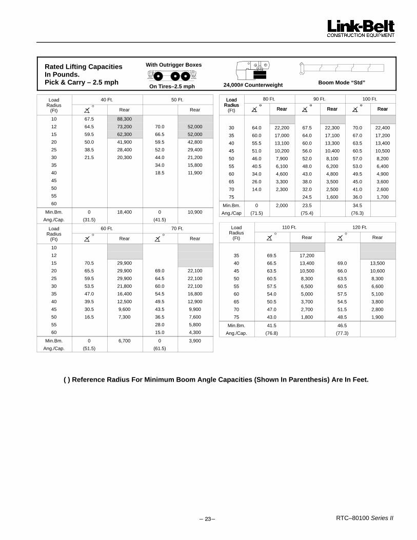
����� RTC–80100 Series II
24,000# Counterweight
With Outrigger Boxes
On Tires–2.5 mphBoom Mode “Std”
Rated Lifting CapacitiesIn Pounds. Pick & Carry – 2.5 mph
Load 40 Ft. 50 Ft.Radius
� °(Ft) � Rear Rear
10 67.5 88,300
12 64.5 73,200 70.0 52,000
15 59.5 62,300 66.5 52,000
20 50.0 41,900 59.5 42,800
25 38.5 28,400 52.0 29,400
30 21.5 20,300 44.0 21,200
35 34.0 15,800
40 18.5 11,900
45
50
55
60
Min.Bm. 0 18,400 0 10,900
Ang./Cap. (31.5) (41.5)
Load 60 Ft. 70 Ft.Radius
� ° � °(Ft) � Rear � Rear
10
12
15 70.5 29,900
20 65.5 29,900 69.0 22,100
25 59.5 29,900 64.5 22,100
30 53.5 21,800 60.0 22,100
35 47.0 16,400 54.5 16,800
40 39.5 12,500 49.5 12,900
45 30.5 9,600 43.5 9,900
50 16.5 7,300 36.5 7,600
55 28.0 5,800
60 15.0 4,300
Min.Bm. 0 6,700 0 3,900
Ang./Cap. (51.5) (61.5)
Load 80 Ft. 90 Ft. 100 Ft.LoadRadius
� ° � ° � °Radius� ° Rear � ° Rear � ° Rear(Ft) � Rear � Rear � Rear
30 64.0 22,200 67.5 22,300 70.0 22,400
35 60.0 17,000 64.0 17,100 67.0 17,200
40 55.5 13,100 60.0 13,300 63.5 13,400
45 51.0 10,200 56.0 10,400 60.5 10,500
50 46.0 7,900 52.0 8,100 57.0 8,200
55 40.5 6,100 48.0 6,200 53.0 6,400
60 34.0 4,600 43.0 4,800 49.5 4,900
65 26.0 3,300 38.0 3,500 45.0 3,600
70 14.0 2,300 32.0 2,500 41.0 2,600
75 24.5 1,600 36.0 1,700
Min.Bm. 0 2,000 23.5 34.5
Ang./Cap (71.5) (75.4) (76.3)
Load 110 Ft. 120 Ft.Radius
� ° � °(Ft) � Rear � Rear
35 69.5 17,200
40 66.5 13,400 69.0 13,500
45 63.5 10,500 66.0 10,600
50 60.5 8,300 63.5 8,300
55 57.5 6,500 60.5 6,600
60 54.0 5,000 57.5 5,100
65 50.5 3,700 54.5 3,800
70 47.0 2,700 51.5 2,800
75 43.0 1,800 48.5 1,900
Min.Bm. 41.5 46.5
Ang./Cap. (76.8) (77.3)
( ) Reference Radius For Minimum Boom Angle Capacities (Shown In Parenthesis) Are In Feet.

�����RTC–80100 Series II
Rated Lifting CapacitiesIn Pounds. On Tires –Stationary – 360� 24,000# Counterweight
With Outrigger Boxes
On Tires–360�Boom Mode “Amax1”
40.Ft. 50 Ft.Load Radius
� ° ° � ° °(Ft) � 360° � 360°
25 38.5 19,700
30 21.5 13,700 44.0 13,500
35 34.0 9,400
40 18.5 6,400
45
50
Min.Bm. 0 12,300 0 5,600
Ang./Cap. (31.5) (41.5)
Do Not Raise Boom Above 47° Boom Angle. Loss Of Back-ward Stability Will Occur Causing a Tipping Condition.
�������
60 Ft. 70 Ft.Load Radius
� ° ° � ° °(Ft) � 360° � 360°
25
30
35 47.0 9,200
40 39.5 6,300
45 30.5 4,000 43.5 3,900
50 16.5 2,200 36.5 2,100
Min.Bm. 0 1,700 32.5
Ang./Cap. (51.5) (52.4)
Do Not Raise Boom Above 47° Boom Angle. Loss Of Back-ward Stability Will Occur Causing a Tipping Condition.
�������
( ) Reference Radius For Minimum Boom Angle Capacities (Shown In Parenthesis) Are In Feet.

����� RTC–80100 Series II
Rated Lifting CapacitiesIn Pounds. On Tires –Stationary – 360� 24,000# Counterweight
With Outrigger Boxes
On Tires–360� Boom Mode “Amax2”
Load 40 Ft. 50 Ft. 60 Ft.Radius
� ° ° � ° ° � ° °(Ft) � 360° � 360° � 360°
25 38.5 19,700
30 21.5 13,700 44.0 15,200
35 34.0 11,100 47.0 12,000
40 18.5 8,100 39.5 9,000
45 30.5 6,700
50 16.5 4,900
Min.Bm. 0 12,300 0 7,300 0 4,400
Ang./Cap.
(31.5) (41.5) (51.5)
Do Not Raise Boom Above 47° Boom Angle. Loss Of Back-ward Stability Will Occur Causing a Tipping Condition.
�������
Load 70 Ft. 80 Ft.Radius
� ° ° � ° °(Ft) � 360° � 360°
40
45 43.5 7,300
50 36.5 5,400 46.0 5,900
55 28.0 4,000 40.5 4,400
60 15.0 2,800 34.0 3,200
65 26.0 2,200
70 14.0 1,400
Min.Bm. 0 2,500 0 1,100
Ang./Cap. (61.5) (71.5)
Do Not Raise Boom Above 47° Boom Angle. Loss Of Back-ward Stability Will Occur Causing a Tipping Condition.
�������
( ) Reference Radius For Minimum Boom Angle Capacities (Shown In Parenthesis) Are In Feet.

�����RTC–80100 Series II
Rated Lifting CapacitiesIn Pounds. On Tires –Stationary – 360� 24,000# Counterweight
With Outrigger Boxes
On Tires–360�Boom Mode “Std”
Load 40 Ft. 50 Ft. 60 Ft.Radius
� ° ° � ° ° � ° °(Ft) � 360° � 360° � 360°
25 38.5 19,700
30 21.5 13,700 44.0 14,600
35 34.0 10,500 47.0 11,000
40 18.5 7,500 39.5 8,100
45 30.5 5,800
50 16.5 4,000
Min.Bm. 0 12,300 0 6,700 0 3,500
Ang./Cap (31.5) (41.5) (51.5)
Do Not Raise Boom Above 47° Boom Angle. Loss Of Back-ward Stability Will Occur Causing a Tipping Condition.
�������
Load 70 Ft. 80 Ft.Radius
� ° ° � ° °(Ft) � 360° � 360°
45 43.5 6,100
50 36.5 4,300 46.0 4,600
55 28.0 2,900 40.5 3,100
60 15.0 1,700 34.0 1,900
Min.Bm. 0 1,400 27.5Ang./Cap. (61.5) (64.1)
Do Not Raise Boom Above 47° Boom Angle. Loss Of Back-ward Stability Will Occur Causing a Tipping Condition.
�������
( ) Reference Radius For Minimum Boom Angle Capacities (Shown In Parenthesis) Are In Feet.

����� RTC–80100 Series II
This Page Intentionally Blank

�����RTC–80100 Series II
Link–Belt Construction Equipment Company Lexington, Kentucky www.linkbelt.com� Link–Belt is a registered trademark. Copyright 2002. All rights reserved. We are constantly improving our products and therefore reserve the right to change designs and specifications.

6 5471 (supersedes 5431)---0506--- J7
RTC---80100 II Link-Belt Cranes
Axle LoadsBase machine with full tank of fueland 24,000 lb (10 886kg) ofcounterweight
Gross VehicleWeight (1)
Upper Facing Front Upper Facing RearFront Axle Rear Axle Group Front Axles Rear Axle Group
lb kg lb kg lb kg lb kg lb kg126,560 57 407 39,742 18 027 86,818 39 380 61,201 27 760 65,359 29 647
Remove outrigger boxes and beams ---17,215 ---7 809 ---6,383 ---2 895 ---10,832 ---4 913 ---6,383 ---2 895 ---10,832 ---4 913Remove main counterweight ---24,182 ---10 969 12,928 5 864 ---37,110 ---16 833 ---31,518 ---14,296 7,336 3 328Cold weather start aid --- ether injec-tor 19 9.5 ---2 ---0.9 21 10 ---2 ---0.9 8 4
Pintle hook, front 20 9 29 13 ---9 ---4 29 13 ---9 ---4Pintle hook, rear 20 9 ---9 ---4 29 13 ---9 ---4 29 13Rear steer indicator 10 4.5 ---2 ---1 12 5 ---2 ---1 12 5Winch roller --- rear winch 110 50 ---82 ---37 192 87 166 75 ---56 ---25Winch roller --- front winch 94 42 ---42 ---4 141 64 119 54 ---25 ---112M auxiliary winch 1,700 771 ---1,143 ---518 284 1,289 2,449 1 110 ---749 ---348500 ft (152m) of 7/8 in (22mm) wirerope on auxiliary winch 862 391 ---579 ---263 1,441 518 1,242 563 ---380 ---172
Air conditioning in operator’s cab 184 83 74 34 110 50 67 30 117 53360˚ swing lock 139 63 35 16 104 47 71 32 68 31Fly brackets to boom base sectionsfor fly options 370 168 497 225 ---127 ---58 ---213 ---97 583 264
31---55 ft (9.45---16.76m) offset fly(stowed) 2,632 1 194 4,223 1 916 ---1,591 ---722 ---2,200 ---998 4,832 2 192
Floodlight to boom base section 10 5 26 12 ---16 ---7 ---18 ---8 28 13100 ton (90.72mt) hook block tofront/rear bumper 1,750 794 2,537 1 151 ---787 ---357 ---1,192 ---541 2,942 1 334
80 ton (72.57mt) hook block to front/rear bumper 1,411 640 2,046 928 ---635 ---288 ---961 ---436 2,372 1 076
50 ton (45.36mt) hook block to front/rear bumper 1,200 544 1,740 789 ---540 ---244 ---817 ---370 2,017 915
12 ton (10.9mt) hook ball to front/rear bumper 722 327 1,047 475 ---325 ---147 ---492 ---223 1,214 551
Auxiliary lifting sheave 120 54 347 157 ---227 ---103 ---254 ---115 374 170
Tire Maximum Load @ 20 mph (32.2km/h)
23.5R25 57,330 lb (26 004kg)
(1) Adjust gross vehicle weight and axle loading according to component weight.Note: All weights are ±3%.
C
BCrane Weight: 89,984 lb (40 816kg), equipped with:S 40---150 ft (12.19 ---45.72m), five section boomS 80 ton (72.57mt) hook blockS One winch with 850 ft (259.08m) of 7/8 in (22mm) ropeS 31---55 ft (9.45 ---16.76m) bi---fold flyS Winch rollerS Auxiliary armS Air conditioning
Drop Off Load Weight: 44,865 lb (20 350kg)S Two outrigger boxes with tow shacklesS 24,000 lb (10 886kg) counterweightS Rear winch with 500 ft (152.40m) of 7/8 in (22mm) ropeS Winch rollerS 12 ton (10.9mt) hook ball
Axle Group Weights
Empty Truck Wt. Bed Length Steer Drivers Trailer A48,500 lb 32 ft 11,900 lb 58,539 lb 68,045 lb 41 in(22 000kg) (9.75m) (5 398kg) (26 553kg) (30 865kg) (1.04m)
B --- 18 in (0.46m) or 24 in (0.61m)
Normal Suspension Collapsed SuspensionC [with 18 in (0.46m) Trailer] 13 ft 8 in (4.17m) 13 ft 5 in (4.09m)C [with 24 in (0.61m) Trailer] 14 ft 2 in (4.32m) 13 ft 11 in (4.24m)
ATransport Configuration and Weights