
RSV 151 / 301 / 601 RSV 151B / 301B / 601B -...
19
RSV 151 / 301 / 601 RSV 151B / 301B / 601B POMPES ROOTS ROOTS PUMPS ROOTS PUMPEN Manuel de l’Utilisateur User’s Manual Benutzerhandbuch Realization/Publication: Alcatel Vacuum Technology France - User’s Manual - Ed 06 - Date: 04/1995 - Part Number: 090582 *090582*
Transcript of RSV 151 / 301 / 601 RSV 151B / 301B / 601B -...

RSV 151 / 301 / 601RSV 151B / 301B / 601B
POMPES ROOTS
ROOTS PUMPS
ROOTS PUMPEN
Manuel de l’UtilisateurUser’s Manual
BenutzerhandbuchReal
izat
ion/
Publ
icat
ion:
Alc
atel
Vac
uum
Tec
hnol
ogy
Fran
ce -
Use
r’s M
anua
l - E
d 06
- D
ate:
04/
1995
- P
art
Num
ber:
090
582 *090582*

Gb
0779
- Ed
ition
04
- Feb
200
8
With 45 years of experience, AVT today has a worldwide presence, through its international network that includes a whole host of experienced subsidiaries, distributors and agents. The fi rst step was the founding of Alcatel Vacuum Products (Hingham- MA) in the United States, thirty years ago, reinforced today by 2 others US subsidiaries in Fremont (CA) and Tempe (AZ).In Europe, AVTF-France headquarters and its subsidiaries, Alcatel Hochvakuumtechnik (Germany), Alcatel Vacuum Technology UK (Scotland), Alcatel Vacuum Technology Benelux (Netherlands), Alcatel Vacuum Systems (Italy) and more recently Adixen Sensistor AB in Sweden (in 2007) form the foundation for the European partner network.In Asia, our presence started in 1993 with Alcatel Vacuum Technology (Japan), and has been strengthened with Alcatel Vacuum Technology Korea (in 1995), Alcatel Vacuum Technology Taiwan (in 2001), Alcatel Vacuum Technology Singapore, Alcatel Vacuum Technology Shanghai (China) (in 2004). This organization is rounded off by more than 40 represensatives based in a variety of continents.Thus, whatever the circumstances, the users of Adixen products can always rely on quick support of our specialists in Vacuum Technology.
Alcatel Vacuum Technology, as part of the Alcatel-Lucent Group, has been supplying vacuum pumps, helium and hydrogen leak detection systems, plasma sensors, vacuum measurement for several years.Thanks to its complete range of products, the company has become an essential player in multiple applications : instrumentation, Research & Developement, industry and semiconductors.Alcatel Vacuum Technology has launched Adixen, its new brand name, in recognition of the company’s international standing in vacuum position.With both ISO 9001 and 14001 certifi cations, the French company is an acknowlegded expert in service and support, and Adixen products have the highest quality and environmental standards.

--- 13 ---
090582 --- Ed. 06 --- 04.1995
INSTRUCTION MANUAL
RSV 151 - RSV 151 BRSV 301 - RSV 301 BRSV 601 - RSV 601 B
CONTENTS
1. DESCRIPTION 15. . . . . . . . . . . . . . . . . . . . . . . . . . . . . . . . . . . . . . . . . . . . . . . .
2. CHARACTERISTICS 17. . . . . . . . . . . . . . . . . . . . . . . . . . . . . . . . . . . . . . . . . . . .
3. OVERALL DIMENSIONS 19. . . . . . . . . . . . . . . . . . . . . . . . . . . . . . . . . . . . . .
4. INSTALLATION - START-UP 20. . . . . . . . . . . . . . . . . . . . . . . . . . . . . . . . . . .
5. MAINTENANCE 22. . . . . . . . . . . . . . . . . . . . . . . . . . . . . . . . . . . . . . . . . . . . . .
6. NOMENCLATURE 37. . . . . . . . . . . . . . . . . . . . . . . . . . . . . . . . . . . . . . . . . . . .

--- 15 ---
090582 --- Ed. 06 --- 04.1995
1. DESCRIPTION
1.1.GENERAL
Roots vacuum boosters are positive displacement pumps operating according to an essentially isochoric compressioncycle (constant volume transfer) with a high pumping rate in a pressure range between 10 and 10 -2 mbar .The pumping mechanism consists of two ”figure-of-eight” pistons rotating in opposite directions and synchronisedthrough a set of gears.The two matched-profile pistons rotate without coming into contact with each other, with a clearance of about onetenth of mm.
1
2
3
4
1 - Inlet
2 - Piston
3 - Outlet
4 - Pump casing
5-Motor stator6-Motor rotor7-Fan8-Casing
9-End plate10-Stator11-End plate
12-Lip seal for dry friction13-Ball bearing14-Gear whell15-Casing
16-Friction ring17-Piston18-Splash
19-Deflector20-Motor sleeve21-Casing link tubes22-Filter
23-Casing pump tubes24-Filter (for ADS version)
18 17 1916 20 5 6 7
15 14 13 12 11 10 9 8 1321
22
23
181924

--- 16 ---
090582 --- Ed. 06 --- 04.1995
The lubrication requirements of these machines are limited to the ball bearings and synchronisation gear train.The two casings containing the oil are isolated from the pumping chamber by a sealing system (lip seal for dry frictionin PTFE + treated friction ring + deflectors) which prevents any possibility of oil contamination of the pumped gases.Roots vacuum boosters operate in conjunction with a roughing pump (RP) which enables the gas flow to be deliveredagainst atmospheric pressure.Consequently, the pumping speed/pressure relation is directly related to the performance characteristics of the associ-ated roughing pump.The power consumption of the Roots machine is according to :- the pumping speed,- the rotation speed,- the pressure difference between inlet and outlet sides.
1.2.PARTICULAR FEATURES OF THE RSV MACHINES
The most noteworthy feature of these machines is the motor coupling which is made only with static parts.The roots RSV units are called ”in vacuum rotor” machines, i.e., the rotor of the electric motor is completely isolated bya stainless steel cylindrical sleeve. This sleeve is centred inside the motor stator and attached to the machine casing,with a static o-ring providing the necessary seal. In this way, any possibility of leaks around the motor/pump couplingis precluded by eliminating the shaft passage with dynamic seal used in conventional set-ups.The oil casings are sealed from the pumping chamber by means of a link tube connecting the casings to the outlet ofthe machine. This avoids the creation of any pressure difference between the pumping chamber and the casing whichwould otherwise be conducive to oil migration. An oil mist filter avoids any oil back-streaming into casing tubes.
1.3.PARTICULAR FEATURES OF THE RSV 151 B, RSV 301 B, RSV 601 B MACHINES
Machines with built-in by-pass valve. This valve provides a means of direct communication between the delivery outletand suction inlet when the maximum permissible differential pressure is exceededIn such an event, part of the gas flow is recycled, there by avoiding any overload on the electric motor.
This device enables the Roots booster and the roughing pump to be started up simultaneously from atmospheric pres-sure without the need of pressure switches for delaying start-up of the roots machine. A higher flow rate is thusobtained in high-pressure ranges, with a resulting reduction in pumping time.
Note : Machines with built-in by-pass valve can operate only with vertical pumping axis arrangement(valve operation under gravity).
1.4.PARTICULAR FEATURES OF THE RSV 151, 301, 601, ADS VERSION
The filter (24) is used to operate with a dry roughing pump. See the corresponding manual.
--- 17 ---
090582 --- Ed. 06 --- 04.1995
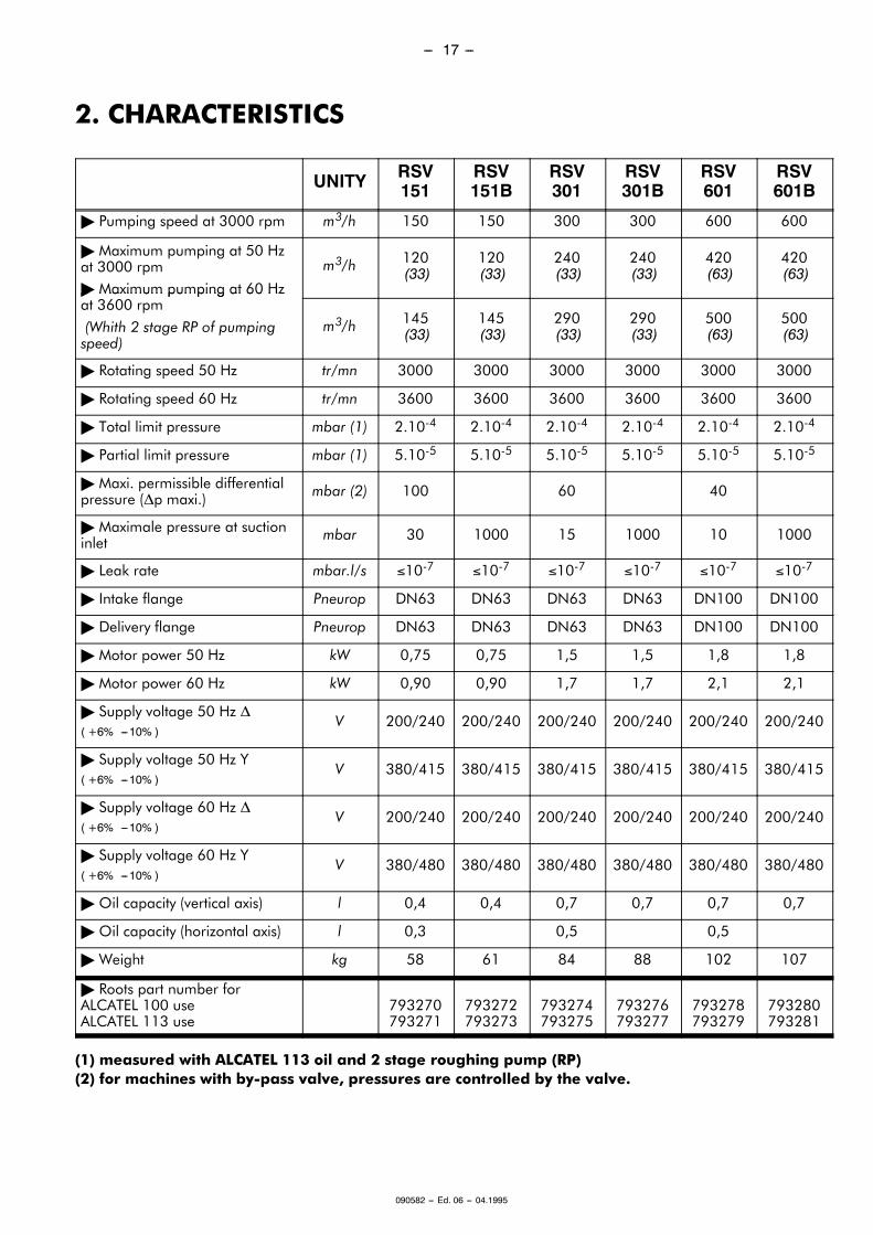
2. CHARACTERISTICS
UNITY RSV151
RSV151B
RSV301
RSV301B
RSV601
RSV601B
" Pumping speed at 3000 rpm m3/h 150 150 300 300 600 600
" Maximum pumping at 50 Hzat 3000 rpm" Maximum pumping at 60 Hz
m3/h 120(33)
120(33)
240(33)
240(33)
420(63)
420(63)
" Maximum pumping at 60 Hzat 3600 rpm
(Whith 2 stage RP of pumpingspeed)
m3/h 145(33)
145(33)
290(33)
290(33)
500(63)
500(63)
" Rotating speed 50 Hz tr/mn 3000 3000 3000 3000 3000 3000
" Rotating speed 60 Hz tr/mn 3600 3600 3600 3600 3600 3600
" Total limit pressure mbar (1) 2.10-4 2.10-4 2.10-4 2.10-4 2.10-4 2.10-4
" Partial limit pressure mbar (1) 5.10-5 5.10-5 5.10-5 5.10-5 5.10-5 5.10-5
" Maxi. permissible differentialpressure (∆p maxi.) mbar (2) 100 60 40
" Maximale pressure at suctioninlet mbar 30 1000 15 1000 10 1000
" Leak rate mbar.l/s ≤10-7 ≤10-7 ≤10-7 ≤10-7 ≤10-7 ≤10-7
" Intake flange Pneurop DN63 DN63 DN63 DN63 DN100 DN100
" Delivery flange Pneurop DN63 DN63 DN63 DN63 DN100 DN100
" Motor power 50 Hz kW 0,75 0,75 1,5 1,5 1,8 1,8
" Motor power 60 Hz kW 0,90 0,90 1,7 1,7 2,1 2,1
" Supply voltage 50 Hz ∆( +6% ---10% )
V 200/240 200/240 200/240 200/240 200/240 200/240
" Supply voltage 50 Hz Y( +6% ---10% )
V 380/415 380/415 380/415 380/415 380/415 380/415
" Supply voltage 60 Hz ∆( +6% ---10% )
V 200/240 200/240 200/240 200/240 200/240 200/240
" Supply voltage 60 Hz Y( +6% ---10% )
V 380/480 380/480 380/480 380/480 380/480 380/480
" Oil capacity (vertical axis) l 0,4 0,4 0,7 0,7 0,7 0,7
" Oil capacity (horizontal axis) l 0,3 0,5 0,5
" Weight kg 58 61 84 88 102 107
" Roots part number forALCATEL 100 useALCATEL 113 use
793270793271
793272793273
793274793275
793276793277
793278793279
793280793281
(1) measured with ALCATEL 113 oil and 2 stage roughing pump (RP)(2) for machines with by-pass valve, pressures are controlled by the valve.

--- 18 ---
090582 --- Ed. 06 --- 04.1995
3. OVERALL DIMENSIONS
3.1.Standard ROOTS RSV pump ( with or without by-pass )
A
B C D
E
F
G
H
I J
K
L
M
N
O
P
Q
DN
DN
R
A B C D E F G H I J K L M N O P Q R DNRSV151 586 190 147 249 135 85 174 16 115 121 95 150 150 168 104 150 16 208 63
RSV301 643 193 140 310 120 122,5 211 24 145 148 125 183 180 204 140 180 24 280 63
RSV601 743 243 190 310 220 122,5 211 25 145 148 125 183 180 204 140 180 24 280 100

--- 19 ---
090582 --- Ed. 06 --- 04.1995
3.2. ROOTS RSV pump ( with by-pass for ADS version )
DN
A
B C D
E
I J
K
L
MDN
F
H
G
Q
P
O
N
S
R
A B C D E F G H I J K L M N O P Q R S DNRSV151 602 190 147 249 135 85 174 16 115 121 95 150 150 168 104 150 16 208 165,5 63
RSV301 643 193 140 310 120 122,5 211 24 145 148 125 183 180 204 140 180 24 280 196,5 63
RSV601 743 243 190 310 220 122,5 211 24 145 148 125 183 180 204 140 180 24 280 196,5 100

--- 20 ---
090582 --- Ed. 06 --- 04.1995
4. INSTALLATION - START-UP
4.1.INSTALLATION
⇒The machine must be handled by means of the two lifting rings on the intake flange.
⇒When fastening to a support frame chassis, use the threaded holes on the two side faces of the stator. All nec-essary precautions must be taken during tightening of fastening bolts to ensure that the stator is not subjected to anydeformation.
⇒Remember to remove the desiccant bag from the pumping chamber.
⇒Machines without by-pass valve can be operated with either vertical or horizontal pumping axis ; thoseequipped with such a valve can be operated only in the vertical axis position.
⇒For the machines without by-pass valve, operating with horizontal pumping axis, the plugs(125) must be removed to permit the oil circulation in the rear casing (4) (see general drawing at theend of the manual).
⇒Procedure- Remove the 4 screws (102) of the rear casing (4), using a 6mm hexagonal socket wrench.- Remove the rear casing (4).- Remove the 2 plugs (125), using a 2mm hexagonal socket wrench.- Reassemble the rear casing, and control the presence of the o-ring (201).
4.2.OIL FILLING
Note : Pumps contains no oil when delivered: oil is shipped in separate containers (see paragraph 5.1)For the machines without by-pass valve, operating with horizontal pumping axis, the plugs (125)sealing oil circulation would have been removed. (see paragraph 4.1 ).
The filler/drain plugs and oil level indicator are located on the same casing (gear side); the two casings are intercon-nected by pipe, thereby allowing simultaneous filling/draining of both casings.
B1
B4
B2
B3 V
V : oil level indicator
Vertical position
- filler plug B1- drain plug B2
Horizontal position
- filler plug B3- drain plug B4
Fill the oil casing with the recommended oil charge (see table page 18). Don’t exceed this quantity.
On filling, wait for a few minutes to allow the oil to run along the inside walls before checking the level.The oil level should be in the middle of the indicator ¦ 2mm.The plugs must be carefully tightened to avoid any leakage into casings under vacuum.

--- 21 ---
090582 --- Ed. 06 --- 04.1995
4.3.CONNECTION OF MOTOR
The machine is driven by a three-phase, asynchronous motor. The motor must be wired up according to the instruc-tions given on the label inside the terminal box to the motor.
The motor piston must rotate anticlockwise when looking from the motor side.
The motor are fitted with a protective probe in the windings. This probe can be used to protect the motor from acci-dental overload.For this purpose, the terminals must be connected to a device which cuts off the power supply to the motor.The fan is powered with 220 V (50/60 Hz).
4.4.START-UP
⇒Machines equipped with a by-pass valve can be started up at the same time as the primary pump. At high pres-sure, the valve lifts up in order to restrict the differential pressure between intake and outlet to a certain threshold.
⇒Machines not fitted with by-pass valve can not be started up until the roughing pump has brought the chamberpressure down to the permissible start-up pressure.This pressure will depend on the flow rate ratio between the roughing pump and the Roots vacuum booster and themaximum permissible pressure difference ∆P.For these machines, pressure switches must be used. These will be fitted in the G 1/2” threaded holes located on theintake flange. The pressure switches will enable the machine to be starded up as soon as the pressure threshold isreached and also provide protection in the event of accidental pressure rise.
Pressure switch Adjustment range Reference number
(mbar) gauge power unit assembly kit
APS 3 1 à 20 786423 053177 060174
APS 4 35 à 200 786424 - 060174
APS 31 3 à 65 786435 053177 060173

--- 22 ---
090582 --- Ed. 06 --- 04.1995
5. STANDARD MAINTENANCE
5.1.OIL LEVEL
⇒Oil levels must be periodically checked if the machine is used under continuous operating conditions. Whenclean gases are being pumped, the oil is subjected to normal mechanical wear only : in such case, oil renewal is rec-ommended every 5000 hours.
Procedure.
⇒Shut down the Roots booster (and roughing pump) and vent the pumping chamber to atmospheric pressure.
B1
B4B2
B3
V V
Vertical positionFiller plug B1
Drain plug B2
Horizontal positionFiller plug B3
Drain plug B4
- Remove the filler plug.
- Remove the drain plug and leave the dirty oil to drainout.
- Screw back the drain plug.
- Fill with the recommended fresh oil charge (seetable page 18). Wait for a few minutes to allow the oil toflow along the inside walls and motor casing link tube beforechecking the level indicator.
- Screw back the filler plug and secure it.
- The oil level should be in themiddle of the indicator ¦ 2mm.
V : oil level indicator

--- 23 ---
090582 --- Ed. 06 --- 04.1995
⇒We recommend the use of ALCATEL oil.
ALCATEL 113 Synthetic oil - 0,5 liter - P/N 064657
ALCATEL 113 Synthetic oil - 2,5 liters - P/N 064659
For non-corrosive applications, the machine can be lubricated with ALCATEL 100 Type mineral oil ; in this case , oneALCATEL 100 oil charge is delivered with the machine ordered with mineral oil.
ALCATEL 100 - mineral oil - 1 liter - P/N 010990
Be careful ! these 2 oil types are not compatible together. For any change consult ALCATEL factory.
5.2.CLEANING
⇒Under certain pumping conditions, deposits may form in the pumping chamber and on the pistons.
⇒These deposits can be removed by disconnecting the intake and delivery pipes, making sure that the motor canno longer be switched on.A suitable solvent and metal brush may be used, turning the pistons by hand.Once these cleaning operations have been completed, change the oil in the casings and check that the piston turnfreely before switching the machine back on.
5.3.ROOTS MAINTENANCE
The wearing parts are easy to replace, requiring particular care and special tools as well as qualified operator. Beforeproceeding to any operation, consult Customer Service for information.To replace these parts, ALCATEL recommends the spare parts kit, the tool kit available on request.
Spare parts kit for Roots RSV 301/301 B RSV 601/601 B P/N. 051992
Spare parts kit for Roots RSV 151/151 B P/N. 051990
Tool kit P/N. 051940

--- 37 ---
090582 --- Ed. 06 --- 04.1995
6. NOMENCLATURE - NOMENKLATUR
TYPES ROOTS
REP DESIGNATION SPECIFICATION BENENNUNG 151
151B
301
301B
601
601B
1 Stator Stator Stator
11
11
11
2 Flasque avant Front plate Vordere Seitenplatte1 1
1 1 1 1
3 Flasque arrière Rear plate Hinteres Seitenplatte1 1
1 1 1 1
4 Carter arrière Rear casing Hinteres Gehäuse1 1
1 1 1 1
5 Carter avant Front casing Vorderesgehause1 1
1 1 1 1
6 Piston menant Driving piston Führungskolben1 1
1 11 1
7 Piston mené Driven piston Geführter Kolben1 1
1 11 1
8 Jeu de roues appariées Paired gear Zahnrad1 1
1 1 1 1
9 Bague de frottement Friction ring Reibungsring 4 4 4 4 4 4 L
10 Bride de roulementarrière Rear bearing flange Hinterer Lagerflansch
2 22 2 2 2
11 Bride de roulementavant Front bearing flange Vorderer Lagerflansch
2 22 2 2 2
12 Déflecteur Deflector Ablenkplatte 4 4 4 4 4 4
13 Bague inférieure Lower ring Unterer Ring 1 1 1 1 1 1
14 Bague supérieure Upper ring Oberer Ring 1 1 1 1 1 1
15 Disque de graissage Lubricating ring Spritzscheibe2 2
2 2 2 2
16 Bague côté moteur Ring on motor side Motorseitiger Ring 1 1 1 1 1 1
17 Entretoise moteur Motor spacer Distanzstück Motor1 1
1 1 1 1
18 Rondelle roulementavant
Washer for front bear-ing Scheibe vord. Lager 1 1 1 1 1 1

--- 38 ---
090582 --- Ed. 06 --- 04.1995
REP
TYPES ROOTS
BENENNUNGSPECIFICATIONDESIGNATIONREP601B
601
301B
301
151B
151
BENENNUNGSPECIFICATIONDESIGNATION
19 Tube de liaison carters Oil connecting pipe Verbindungsrohr2 2
2 22 2
20 Capot de ventilation Fan cover Lüfterhaube1 1
1 1 1 1
21 Rondelle Washer scheibe1 1
1 1 1 1
22 Tubulure Pipe Evakuierungsleitung1 1
1 1 1 1
23Protecteur DN 63Protecteur DN 100
NW 63 Cover plateNW 100 Cover plate
DN 63 DeckelDN 100 Deckel
2 2 2 22 2
24 Câle de réglage Adjustment shim Distanzcheibe10 10
10 10 10 10L
27 Goupille ∅ 8 Pin Zylinderstift4 4
4 4 4 4
28 Bouchon Plug Stopfen 1 1 1 1 1 1
33 Clapet de by-pass By-pass valve Bypass Ventil1
1 1
34 Couvercle Cover Deckel1
1 1
35 Patin Shoe Gleitstock 1 1 1 L
36 Vis de réglage Adjustment screw Regelschraube1
1 1
37 Ressort Spring Feder 1 1 1 L
38 Entretoise ventilateur Fan spacer Distanzstück fûr Lüfter-haube
3 3 3 3
39 Bague Ring Ring1 1
1 1 1 1
44 Goujon Pin Stift1 1
1 1 1 1
46 Déflecteur Deflector Ablenkplatte1 1
1 1 1 1
56 Tube anti-extrusion Safety tube Rohr1 1
1 1 1 1
57 Rondelle pour amortis-seur
Washer for shockabsorber
Scheibe für Swingme-tal
8 8 8 8 8 8
58 Rondelle caoutchouc Washer Scheibe 4 4 4 4 4 4
101Vis CHc M10-25Vis CHc M10-30
ScrewScrew
SchraubeSchraube
2 21 1 2 2
102Vis CHc M8-55Vis CHc M8-40
ScrewScrew
SchraubeSchraube
8 88 8 8 8

--- 39 ---
090582 --- Ed. 06 --- 04.1995
REP
TYPES ROOTS
BENENNUNGSPECIFICATIONDESIGNATIONREP601B
601
301B
301
151B
151
BENENNUNGSPECIFICATIONDESIGNATION
103 Vis CHc M8 x 30 Screw Schraube 4 4
104 Vis CHc M8-25 Screw Schraube 4 4 4 4 4 4
106Vis CHc M8-16Vis CHc M8-20
ScrewScrew
SchraubeSchraube
8 812 12 12 12
107 Vis CHc M5-12 Screw Schraube 6 6 2 2 2 2
108 Vis CHc M5-8 Screw Schraube 4 4 3 3 3 3
109 Vis H M8-10 Screw Schraube 6 6 6 6 6 6
110 Vis CBLZ M3 x 6 Screw Schraube 1 1
111 Rondelle Washer Unterlegscheibe 5 5 5 5 5 5
112 Rondelle Washer Unterlegscheibe 2 2 2 2 2 2 L
113 Rondelle Washer Unterlegscheibe 24 24 24 24 24 24 L
114 Rondelle Washer Unterlegscheibe 1 1
115 Rondelle Washer Unterlegscheibe 18 18 18 18 18 18 L
116 Rondelle Washer Unterlegscheibe 6 6 6 6 6 6 L
118 Vis CHc M4-16 Screw Schraube 4 4 4 4
119 Ecrou HM 4U Screw nut Mutter 4 4 4 4
120 Rondelle ∅ 4 Washer Unterlegscheibe 4 4 4 4
121 Rondelle Washer Unterlegscheibe 4 4 4 4
122Vis CHc M6-10Vis CHc M10-45
Screw Schraube4
14 4
123 Rondelle Washer Unterlegscheibe 4 4 4
124 Ecrou HM 10 Screw nut Mutter 1 1 1 1 1 1
125 Vis Hc M4 Screw Schraube 2 2 2 2 2 2
126Vis HM 8 x 25Vis HM 10 x 25
ScrewScrew
SchraubeSchraube
4 44 4
127 Vis CHc M4 x 50 Screw Schraube 4 4
128 Rondelle M4 Washer Unterlegscheibe 4 4
129 Ecrou HM 4 Nut Mutter 4 4
130 Rondelle Washer Unterlegscheibe 4 4
150 Roulement à billes Ball bearing Kugellager 4 4 4 4 4 4 L
151 Grille de protection Screening grid Abschirmgitter 1 1
152 Cartouche filtre Oil filter Filtereinsatz 1 1 1 1 1 1 L
153 Bouchon Plug Stopfen 5 5 5
154Aiguille ∅ 4Aiguille ∅ 4
NeedleNeedle
NadelNadel
1 11 1 1 1

--- 40 ---
090582 --- Ed. 06 --- 04.1995
REP
TYPES ROOTS
BENENNUNGSPECIFICATIONDESIGNATIONREP601B
601
301B
301
151B
151
BENENNUNGSPECIFICATIONDESIGNATION
155 Câble Cable Kabel − − − − − −
156 Cosse ∅ 5 Lug Kabelschuh 3 3 3 3 3 3
157Cosse ∅ 3Passe-fil
LugCable feed throughsleeve
KabelschuhKugellager
1 12 2 2 2
158GaineBarrette de connection
SheathConnection bar
MantelAnschlussleiste
− −
− − − −
159 Gaine Sheath Mantel --- --- --- --- --- ---
160 Voyant niveau d’huile Oil level sight glass Ölschauglas 1 1 1 1 1 1 L
161 Ventilateur Fan Ventilator1 1
1 1 1 1
162 Moteur 3PH sous vide 3 ø motor Drehstrommotor1 1
1 11 1
163 Anneau de levage Lifting ring Ringschraube 2 2 2 2 2 2
166 Collier ty-rap Ty-rap collar Stellring 1 1 1 1 1 1
167 Connecteur embase Connector Verbinder 1 1 1 1 1 1
168 Collier ty-rap Ty-rap collar Stellring 1 1 1 1
171 Raccord tube Pipe connecting part Rohrverschraubung 1 1 1 1 1 1
200 Joint à lèvre Lip seal Lippendichtung 4 4 4 4 4 4 l
201Joint torique ∅3x165Joint torique ∅3x218
O---ringO---ring
O-RingO-Ring
4 44 4 4 4
l
l
202Joint torique ∅3x134,5Joint torique ∅3x154,5
O-ringO-ring
O-RingO-Ring
1 11 1 1 1
l
l
203 Joint torique ∅ 3x24 O-ring O-Ring 1 1 1 1 1 1 l
204 Joint torique ∅2,7x18,4 O-ring O-Ring 5 5 5 l
205 Joint torique ∅ 2x30 O-ring O-Ring 4 4 4 4 4 4 l
206Joint torique ∅2,4x10,3Joint torique ∅ 2x12
O-ringO-ring
O-RingO-Ring
5 55 5 5 5
l
l
208Joint tor. ∅ 5,33x37,47Joint tor. ∅ 5,33x56,52
O-ringO-ring
O-RingO-Ring
11 1
l
l
209Joint torique ∅ 3x60Joint torique ∅ 3x80
O-ringO-ring
O-RingO-Ring
11 1
l
l
400 Vis CLS 3.5 M12 Screw Schraube 2 2 2 2
L l Element du lot de maintenance/ Part from the spare parts kit/ Teil aus dem Wartungssatz


CHINAAlcatel Vacuum Technology, ShanghaiN°82 Lane 887 Zuchongzhi RoadZhangjiang High-Tech Park,Shanghai 201203 ChinaTel. (86) 21 5027 0628Fax. (86) 21 3895 3815
FRANCEAlcatel Vacuum Technology France98, avenue de Brogny - BP 206974009 Annecy cedexFranceTel. (33) 4 50 65 77 77Fax. (33) 4 50 65 77 89
GERMANYAlcatel Hochvakuumtechnik GmbHAm Kreuzeck 10 - Postfach 115197877 Wertheim GermanyTel. (49) 9342 9610 0Fax. (49) 9342 9610 30
ITALYAlcatel Vacuum SystemsVia Trento, 3020059 Vimercate (Mi) ItalyTel. (39) 0396 86 38 55Fax. (39) 039 66 71 25
Alcatel Vacuum Technology France - 98, avenue de Brogny - BP 2069 - 74009 Annecy cedex - FRANCETel. (33) 4 50 65 77 77 - Fax. (33) 4 50 65 77 89
Web site: www.adixen.com
JAPANAlcatel-Lucent Japan Ltd.1-9-4 Kita Shin-YokohamaKohoku-kuYokohama, Kanagawa 223-0059JapanTel. (81) 3 6431 7130Fax. (81) 45 544 0049
KOREAAlcatel Vacuum Technology Korea447 Banwol-dong, Hawsung-si,445-330 Kyungki-do,South KoreaTel. (82) 031-206-6277Fax. (82) 031-204-6279
NETHERLANDSALCATEL Vacuum Technology Benelux Landzichtweg 60NL 4105 DP CulemborgThe NetherlandsTel. (31) 345 478 400Fax. (31) 345 531 076
SINGAPOREAlcatel-Lucent Singapore49 Jalan Pemimpin#01-02 APS Industrial Building577203SingaporeTel. (65) 6254 0828Fax. (65) 6254 7018
SWEDENAdixen Sensistor AB.Box 76 SE-581 02 LinköpingSweden Tel. 46 (0)13 35 59 00Fax. 46 (0)13 35 59 01
TAIWANAlcatel Vacuum Technology TaïwanNo. 169-3, Sec.1, Kang-Leh RdSong-Lin Village, Hsin-Feng 304Hsin-Chu CountyTaïwan - R.O.C.Tel. (886) 3 559 9230Fax.(886) 3559 9231
UNITED KINGDOMAlcatel Vacuum Technology UK Ltd8 Bain Square - Kirkton CampusLivingston - West LothianEH54 7DQ - ScotlandUnited KingdomTel. (44) 1 506 418 000Fax. (44) 1 506 418 002
USAAlcatel Vacuum Products67, Sharp StreetHingham - MA 02043USATel. (1) 781 331 4200Fax. (1) 781 331 4230