R&S®EB500 Monitoring Receiver Powerful and compact · Monitoring Receiver Powerful and compact ......
28
Radiomonitoring & Radiolocation Product Brochure | 05.00 R&S®EB500 Monitoring Receiver Powerful and compact
Transcript of R&S®EB500 Monitoring Receiver Powerful and compact · Monitoring Receiver Powerful and compact ......

Ra
diom
onito
ring
& Ra
diol
ocat
ion
Prod
uct B
roch
ure
| 05.
00
R&S®EB500Monitoring ReceiverPowerful and compact
EB500_bro_en_5214-3800-12.indd 1 16.04.2015 09:35:45

2
The R&S®EB500 monitoring receiver was specially developed for signal search, radiomonitoring, radio detection and spectrum monitoring in powerful, compact systems. Due to the receiver's compact size as well as its excellent performance and energy-saving design, it is the perfect tool for radiomonitoring applications. It performs ITU-compliant measurements and meets the requirements of security authorities and organizations. The receiver is ideal for both stationary and mobile/vehicular applications because it can be operated via the front panel or remotely controlled via LAN.
R&S®EB500Monitoring ReceiverAt a glance
The R&S®EB500 features a wide frequency range (8 kHz to 6 GHz), outstanding receive characteristics, 20 MHz realtime bandwidth and a wealth of functions.
Thanks to its sophisticated preselection stages, the re-ceiver can be directly connected to a wideband monitoring antenna. This is an operating scenario that requires high large-signal immunity and high sensitivity, particularly in the presence of many strong signals.
An upgrade kit is available to turn the monitoring receiver into a high-performance, single-channel direction finder.
All results are output via the receiver's LAN interface, including: ❙ Spectra (realtime operation and scan mode) ❙ Waterfall (spectrogram) ❙ Demodulated audio information ❙ Level measurement data ❙ I/Q baseband data
Key facts ❙ ITU-compliant measurements and applications for security authorities and organizations
❙ Wide frequency range: 8 kHz to 6 GHz (base unit: 20 MHz to 3.6 GHz)
❙ 20 MHz realtime bandwidth ❙ Numerous options to increase performance ❙ Various result displays ❙ Integration into customer-specific software packages from third-party suppliers thanks to open, documented, remote control interface and data formats
❙ Internal recording and replay of spectra and waterfall data (for receivers with front panel operation or for external R&S®EB500-GUI software)
❙ Map display with GPS position (for receivers with front panel operation or for external R&S®EB500-GUI software)
R&S®EB500 with display. R&S®EB500 without display.
EB500_bro_en_5214-3800-12.indd 2 16.04.2015 09:35:47
Rohde & Schwarz R&S®EB500 Monitoring Receiver 3
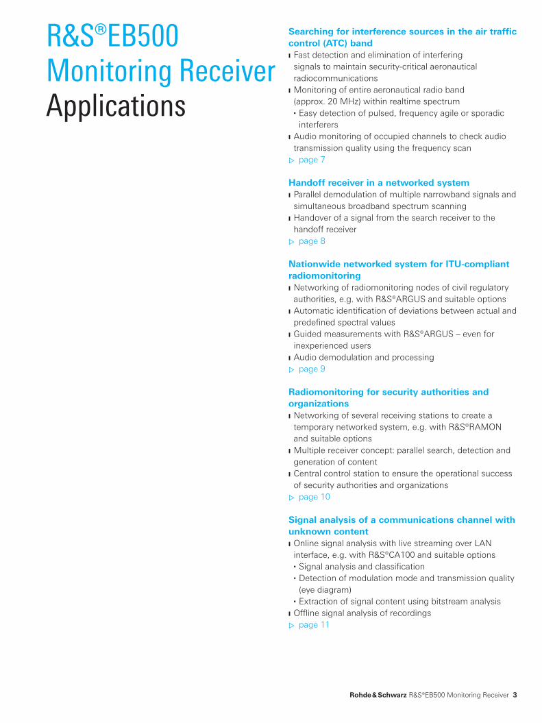
R&S®EB500Monitoring ReceiverApplications
Searching for interference sources in the air traffic control (ATC) band ❙ Fast detection and elimination of interfering signals to maintain security-critical aeronautical radiocommunications
❙ Monitoring of entire aeronautical radio band (approx. 20 MHz) within realtime spectrum
■ Easy detection of pulsed, frequency agile or sporadic interferers
❙ Audio monitoring of occupied channels to check audio transmission quality using the frequency scan ▷ page 7
Handoff receiver in a networked system ❙ Parallel demodulation of multiple narrowband signals and simultaneous broadband spectrum scanning
❙ Handover of a signal from the search receiver to the handoff receiver ▷ page 8
Nationwide networked system for ITU-compliant radiomonitoring ❙ Networking of radiomonitoring nodes of civil regulatory authorities, e.g. with R&S®ARGUS and suitable options
❙ Automatic identification of deviations between actual and predefined spectral values
❙ Guided measurements with R&S®ARGUS – even for inexperienced users
❙ Audio demodulation and processing ▷ page 9
Radiomonitoring for security authorities and organizations ❙ Networking of several receiving stations to create a temporary networked system, e.g. with R&S®RAMON and suitable options
❙ Multiple receiver concept: parallel search, detection and generation of content
❙ Central control station to ensure the operational success of security authorities and organizations ▷ page 10
Signal analysis of a communications channel with unknown content ❙ Online signal analysis with live streaming over LAN interface, e.g. with R&S®CA100 and suitable options
■ Signal analysis and classification ■ Detection of modulation mode and transmission quality (eye diagram)
■ Extraction of signal content using bitstream analysis ❙ Offline signal analysis of recordings ▷ page 11
EB500_bro_en_5214-3800-12.indd 3 16.04.2015 09:35:47
4
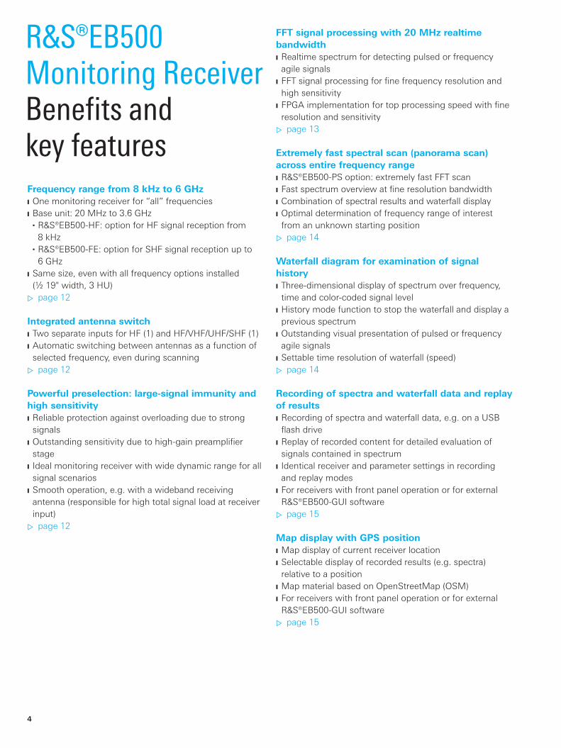
FFT signal processing with 20 MHz realtime bandwidth ❙ Realtime spectrum for detecting pulsed or frequency agile signals
❙ FFT signal processing for fine frequency resolution and high sensitivity
❙ FPGA implementation for top processing speed with fine resolution and sensitivity ▷ page 13
Extremely fast spectral scan (panorama scan) across entire frequency range ❙ R&S®EB500-PS option: extremely fast FFT scan ❙ Fast spectrum overview at fine resolution bandwidth ❙ Combination of spectral results and waterfall display ❙ Optimal determination of frequency range of interest from an unknown starting position ▷ page 14
Waterfall diagram for examination of signal history ❙ Three-dimensional display of spectrum over frequency, time and color-coded signal level
❙ History mode function to stop the waterfall and display a previous spectrum
❙ Outstanding visual presentation of pulsed or frequency agile signals
❙ Settable time resolution of waterfall (speed) ▷ page 14
Recording of spectra and waterfall data and replay of results ❙ Recording of spectra and waterfall data, e.g. on a USB flash drive
❙ Replay of recorded content for detailed evaluation of signals contained in spectrum
❙ Identical receiver and parameter settings in recording and replay modes
❙ For receivers with front panel operation or for external R&S®EB500-GUI software ▷ page 15
Map display with GPS position ❙ Map display of current receiver location ❙ Selectable display of recorded results (e.g. spectra) relative to a position
❙ Map material based on OpenStreetMap (OSM) ❙ For receivers with front panel operation or for external R&S®EB500-GUI software ▷ page 15
R&S®EB500Monitoring ReceiverBenefits and key featuresFrequency range from 8 kHz to 6 GHz ❙ One monitoring receiver for “all” frequencies ❙ Base unit: 20 MHz to 3.6 GHz
■ R&S®EB500-HF: option for HF signal reception from 8 kHz
■ R&S®EB500-FE: option for SHF signal reception up to 6 GHz
❙ Same size, even with all frequency options installed (½ 19" width, 3 HU) ▷ page 12
Integrated antenna switch ❙ Two separate inputs for HF (1) and HF/VHF/UHF/SHF (1) ❙ Automatic switching between antennas as a function of selected frequency, even during scanning ▷ page 12
Powerful preselection: large-signal immunity and high sensitivity ❙ Reliable protection against overloading due to strong signals
❙ Outstanding sensitivity due to high-gain preamplifier stage
❙ Ideal monitoring receiver with wide dynamic range for all signal scenarios
❙ Smooth operation, e.g. with a wideband receiving antenna (responsible for high total signal load at receiver input) ▷ page 12
EB500_bro_en_5214-3800-12.indd 4 16.04.2015 09:35:47

Rohde & Schwarz R&S®EB500 Monitoring Receiver 5
3+1 receivers in one instrument ❙ R&S®EB500-DDC option: three additional demodulation channels
❙ Four software receivers in one instrument thanks to four demodulation channels (anywhere within realtime bandwidth)
❙ Output of demodulated data as separate data streams via LAN interface ▷ page 20
Ethernet interface for remote control and/or data transmission ❙ 1 Gbit Ethernet LAN interface for receiver remote control and result processing using Rohde & Schwarz system software (e.g. R&S®ARGUS, R&S®RAMON, R&S®CA100)
❙ Documented interface description for flexible programming and data processing, even with customer-specific software package ▷ page 20
Receiver remote control and data recording ❙ R&S®EB500-Control software package for receiver remote control via 1 Gbit LAN interface
❙ Documentation of results on a PC (e.g. spectra or audio content), also for replaying recorded data for offline analysis ▷ page 21
ITU-compliant measurements in the receiver ❙ R&S®EB500-IM option: ITU-compliant measurement of signal parameters for AM, FM and PM-modulated signals (e.g. modulation index, occupied bandwidth and phase deviation)
❙ Offline measurement of digitally modulated signals using the R&S®CA100IS software and suitable options (in line with ITU recommendation SM.1600) ▷ page 22
Detection of selective call services ❙ R&S®EB500-SL option: detection of audio-based selective calls and listing of received selective call standards
❙ Result filtering according to relevant standards ▷ page 23
DC operation (e.g. from vehicle battery) ❙ DC power supply (10 V to 32 V DC) of receiver ❙ Space-saving vehicle installation ▷ page 23
Polychrome spectrum to distinguish superimposed, pulsed signals ❙ Display of time behavior (frequency of occurrence) of pulsed signals using color coding (for all realtime bandwidths)
❙ Settable occurrence frequency threshold ❙ Separate display of pulsed signals (superimposed in frequency, time and level) ▷ page 16
Video spectrum for display of subcarriers and transmission rates ❙ Spectrum display of demodulated signal ❙ Clear display of subcarriers, e.g. 19 kHz pilot tone ❙ Squared video spectrum to estimate the transmission rate (baud rate) of a digitally modulated signal
❙ Combination of spectral results and waterfall display ▷ page 17
Parallel signal processing of spectral path and demodulation path ❙ Two parallel signal processing paths for spectrum and demodulation
❙ Interference-free demodulation with parallel display of realtime spectrum and waterfall display
❙ Seamless I/Q baseband data stream for signal analysis ❙ Independent setting of bandwidth and center frequency ▷ page 18
Level measurements with “real” wideband detector ❙ Wideband level measurements up to 20 MHz bandwidth for sophisticated, digitally modulated signals ▷ page 19
Frequency scan and memory scan for audio demodulation on changing channels ❙ Frequency scan: continuous scanning of adjacent channels, automatic demodulation of channels where level exceeds squelch, e.g. in ATC band
❙ Memory scan: scanning of different radio services with variable step size and demodulation mode
❙ Convenient scanning for active signals and quick availability of audio content ▷ page 19
EB500_bro_en_5214-3800-12.indd 5 16.04.2015 09:35:47
6
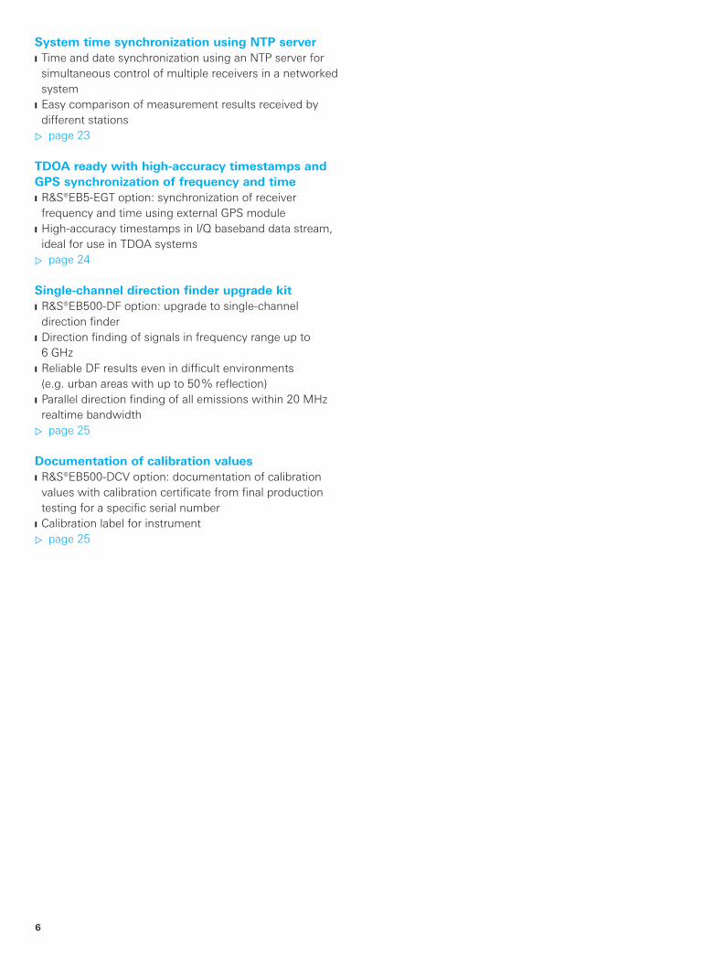
System time synchronization using NTP server ❙ Time and date synchronization using an NTP server for simultaneous control of multiple receivers in a networked system
❙ Easy comparison of measurement results received by different stations ▷ page 23
TDOA ready with high-accuracy timestamps and GPS synchronization of frequency and time ❙ R&S®EB5-EGT option: synchronization of receiver frequency and time using external GPS module
❙ High-accuracy timestamps in I/Q baseband data stream, ideal for use in TDOA systems ▷ page 24
Single-channel direction finder upgrade kit ❙ R&S®EB500-DF option: upgrade to single-channel direction finder
❙ Direction finding of signals in frequency range up to 6 GHz
❙ Reliable DF results even in difficult environments (e.g. urban areas with up to 50 % reflection)
❙ Parallel direction finding of all emissions within 20 MHz realtime bandwidth ▷ page 25
Documentation of calibration values ❙ R&S®EB500-DCV option: documentation of calibration values with calibration certificate from final production testing for a specific serial number
❙ Calibration label for instrument ▷ page 25
EB500_bro_en_5214-3800-12.indd 6 16.04.2015 09:35:47
Rohde & Schwarz R&S®EB500 Monitoring Receiver 7
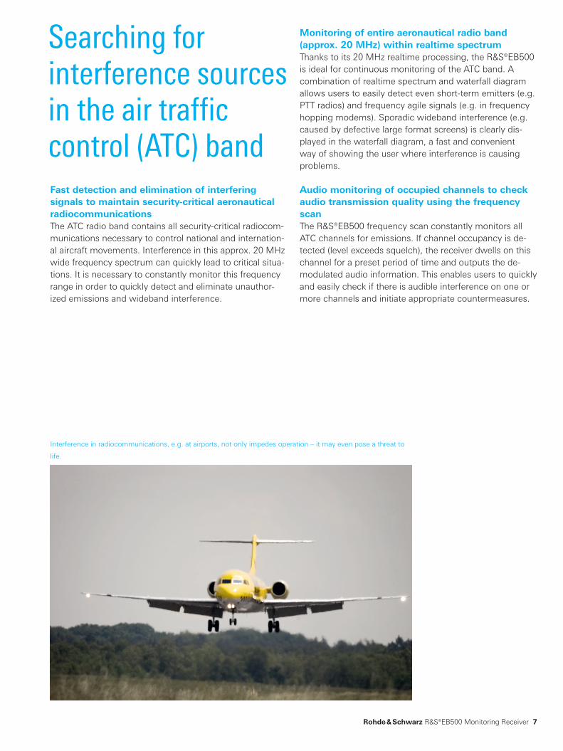
Monitoring of entire aeronautical radio band (approx. 20 MHz) within realtime spectrumThanks to its 20 MHz realtime processing, the R&S®EB500 is ideal for continuous monitoring of the ATC band. A combination of realtime spectrum and waterfall diagram allows users to easily detect even short-term emitters (e.g. PTT radios) and frequency agile signals (e.g. in frequency hopping modems). Sporadic wideband interference (e.g. caused by defective large format screens) is clearly dis-played in the waterfall diagram, a fast and convenient way of showing the user where interference is causing problems.
Audio monitoring of occupied channels to check audio transmission quality using the frequency scanThe R&S®EB500 frequency scan constantly monitors all ATC channels for emissions. If channel occupancy is de-tected (level exceeds squelch), the receiver dwells on this channel for a preset period of time and outputs the de-modulated audio information. This enables users to quickly and easily check if there is audible interference on one or more channels and initiate appropriate countermeasures.
Searching for interference sources in the air traffic control (ATC) band
Interference in radiocommunications, e.g. at airports, not only impedes operation – it may even pose a threat to
life.
Fast detection and elimination of interfering signals to maintain security-critical aeronautical radiocommunicationsThe ATC radio band contains all security-critical radiocom-munications necessary to control national and internation-al aircraft movements. Interference in this approx. 20 MHz wide frequency spectrum can quickly lead to critical situa-tions. It is necessary to constantly monitor this frequency range in order to quickly detect and eliminate unauthor-ized emissions and wideband interference.
EB500_bro_en_5214-3800-12.indd 7 16.04.2015 09:35:47

8
Handoff receiver in a networked system
Parallel demodulation of multiple narrowband signals and simultaneous broadband spectrum scanningMultiple R&S®EB500 receivers can be combined with a fast and powerful search receiver (e.g. the R&S®ESMD) and operated as a system. The handoff receiver (R&S®EB500) demodulates signals and produces audio or I/Q data streams, while the search receiver quickly searches for other signals with an extremely high level of sensitivity. A separate handoff receiver is required for each signal to be processed in parallel.
Handover of a signal from the search receiver to the handoff receiverThe handover of a signal from the R&S®ESMD (search re-ceiver) to an R&S®EB500 (handoff receiver) can be carried out from the user workstation running the R&S®RAMON radiomonitoring software. The major advantage of this system configuration is that fast signal scanning across a wide frequency range takes place at the same time as nar-rowband generation of multiple audio or I/Q data streams. This allows the user to achieve optimum results in a mini-mum of time.
Networked system: Multiple R&S®EB500 receivers can be
operated together with an R&S®ESMD.
EB500_bro_en_5214-3800-12.indd 8 16.04.2015 09:35:48

Rohde & Schwarz R&S®EB500 Monitoring Receiver 9
Networking of radiomonitoring nodes of civil regulatory authoritiesTo perform civil regulatory authorities' radiomonitoring tasks in line with ITU recommendations, all available re-ceiving nodes must be networked. This includes both stationary and vehicular radiomonitoring stations. The R&S®ARGUS monitoring software is ideal for networking and remotely controlling nationwide radiomonitoring sys-tems as well as small regional networks. Interference can be quickly and effectively located and eliminated, even in a frequency spectrum with steadily increasing occupancy (e.g. police radio, VHF radio, aeronautical radio, DECT, radio for security authorities and organizations, mobile phones and WLAN).
Continuous, networked monitoring is the only way to en-sure smooth operations in dense radiocommunications traffic.
Automatic identification of deviations between actual and predefined spectral valuesDeviations between actual spectral values and a pre-defined mask are automatically identified, allowing differ-ences in the signal scenario to be quickly and conveniently detected. If one of the measurement parameters is outside the defined value range, the R&S®ARGUS software imme-diately generates an automatic alarm message. This type of user-friendly parameter identification is in line with ITU recommendations and can be used to identify interfering signals, detect unlicensed emissions, verify compliance with applicable licenses and much more.
Guided measurements with R&S®ARGUS – even for inexperienced usersOne notable R&S®ARGUS feature is the “guided measure-ment” function. The user selects a measurement task (e.g. measurement of field strength or occupied bandwidth), and R&S®ARGUS automatically configures the appropriate parameters of the selected monitoring receiver. It also au-tomatically selects the receiving antenna based on the se-lected frequency range and required polarization. Thanks to this convenient function, even inexperienced users can effectively operate the R&S®EB500 monitoring receiver.
Audio demodulation and processingReceived and demodulated audio content is recorded and can be output online over the operating station's loud-speakers to ensure that different stations are monitoring the same signal. The impact of interferers on traffic chan-nels transmitting audio content is also documented.
Nationwide networked system for ITU-compliant radiomonitoring
Spectrum of a DVB-T transmitter with a mask overlay.
EB500_bro_en_5214-3800-12.indd 9 16.04.2015 09:35:49
10
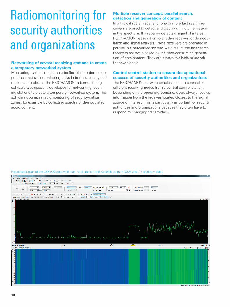
Radiomonitoring for security authorities and organizations
Multiple receiver concept: parallel search, detection and generation of contentIn a typical system scenario, one or more fast search re-ceivers are used to detect and display unknown emissions in the spectrum. If a receiver detects a signal of interest, R&S®RAMON passes it on to another receiver for demodu-lation and signal analysis. These receivers are operated in parallel in a networked system. As a result, the fast search receivers are not blocked by the time-consuming genera-tion of data content. They are always available to search for new signals.
Central control station to ensure the operational success of security authorities and organizationsThe R&S®RAMON software enables users to connect to different receiving nodes from a central control station. Depending on the operating scenario, users always receive information from the receiver located closest to the signal source of interest. This is particularly important for security authorities and organizations because they often have to respond to changing transmitters.
Fast spectral scan of the GSM900 band with max. hold function and waterfall diagram (GSM and LTE signals visible).
Networking of several receiving stations to create a temporary networked systemMonitoring station setups must be flexible in order to sup-port localized radiomonitoring tasks in both stationary and mobile applications. The R&S®RAMON radiomonitoring software was specially developed for networking receiv-ing stations to create a temporary networked system. The software optimizes radiomonitoring of security-critical zones, for example by collecting spectra or demodulated audio content.
EB500_bro_en_5214-3800-12.indd 10 16.04.2015 09:35:50

Rohde & Schwarz R&S®EB500 Monitoring Receiver 11
Online signal analysis with live streaming over LAN interfaceThe R&S®EB500 provides a continuous I/Q baseband data stream for online analysis of a max. 1 MHz signal channel over the 1 Gbit LAN interface. The R&S®CA100 software uses this data stream to analyze and classify the signal on an external PC. It recognizes modulation modes and displays transmission quality in an eye diagram. Bitstream analysis allows users to extract the message content from the received signal.
If the monitoring receiver is equipped with DDCs (R&S®EB500-DDC option), the R&S®CA100 software can process up to three signals in parallel.
Offline signal analysis of recordingsThe R&S®CA100 software can save data packets on a PC's hard disk for later detailed offline analysis. Complex signal forms are examined under different conditions to obtain more detailed analysis results.
Signal analysis of a communications channel with unknown content
Online and offline signal analysis, from eye diagram to message content.
EB500_bro_en_5214-3800-12.indd 11 16.04.2015 09:35:50
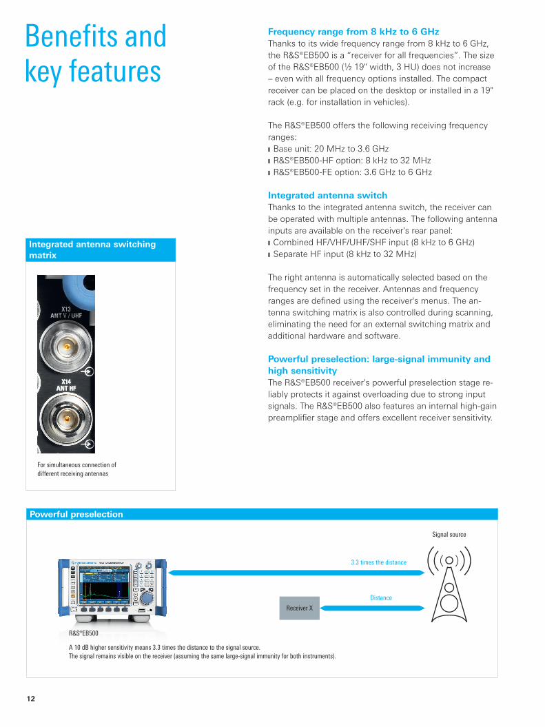
Signal source
3.3 times the distance
Distance
Receiver X
¸EB500
A 10 dB higher sensitivity means 3.3 times the distance to the signal source. The signal remains visible on the receiver (assuming the same large-signal immunity for both instruments).
12
Benefits and key features
Frequency range from 8 kHz to 6 GHzThanks to its wide frequency range from 8 kHz to 6 GHz, the R&S®EB500 is a “receiver for all frequencies”. The size of the R&S®EB500 (½ 19" width, 3 HU) does not increase – even with all frequency options installed. The compact receiver can be placed on the desktop or installed in a 19" rack (e.g. for installation in vehicles).
The R&S®EB500 offers the following receiving frequency ranges: ❙ Base unit: 20 MHz to 3.6 GHz ❙ R&S®EB500-HF option: 8 kHz to 32 MHz ❙ R&S®EB500-FE option: 3.6 GHz to 6 GHz
Integrated antenna switchThanks to the integrated antenna switch, the receiver can be operated with multiple antennas. The following antenna inputs are available on the receiver's rear panel: ❙ Combined HF/VHF/UHF/SHF input (8 kHz to 6 GHz) ❙ Separate HF input (8 kHz to 32 MHz)
The right antenna is automatically selected based on the frequency set in the receiver. Antennas and frequency ranges are defined using the receiver's menus. The an-tenna switching matrix is also controlled during scanning, eliminating the need for an external switching matrix and additional hardware and software.
Powerful preselection: large-signal immunity and high sensitivityThe R&S®EB500 receiver's powerful preselection stage re-liably protects it against overloading due to strong input signals. The R&S®EB500 also features an internal high-gain preamplifier stage and offers excellent receiver sensitivity.
For simultaneous connection of different receiving antennas
Integrated antenna switching matrix
Powerful preselection
EB500_bro_en_5214-3800-12.indd 12 16.04.2015 09:35:50
Rohde & Schwarz R&S®EB500 Monitoring Receiver 13
FFT signal processing with 20 MHz realtime bandwidthRealtime processing of the frequency spectrum is essen-tial for detecting pulsed or frequency agile signals. FFT signal processing allows all spectral information to be displayed simultaneously. The realtime spectrum is calcu-lated without sweeping or scanning and offers detection in realtime. The calculation time is negligible due to FPGA implementation.
FFT realtime processing also offers excellent frequency resolution plus very high sensitivity.
This combination of speed, frequency resolution and sen-sitivity makes the receiver ideal for a very wide range of applications. Users get detailed information about the fre-quency spectrum. Pulsed, time-variant and frequency agile signals are reliably detected and displayed in the spectrum or waterfall diagram. During realtime operation, signals can be demodulated in parallel, without interruptions.
The R&S®EB500 base unit features a realtime bandwidth of 20 MHz. Depending on the requirements, the realtime spectrum span can be stepwise reduced to a minimum bandwidth of 1 kHz.
A detailed description of R&S®EB500 realtime pro-cessing is available in the “Realtime FFT processing in Rohde & Schwarz receivers” application brochure (PD 3606.8308.92).
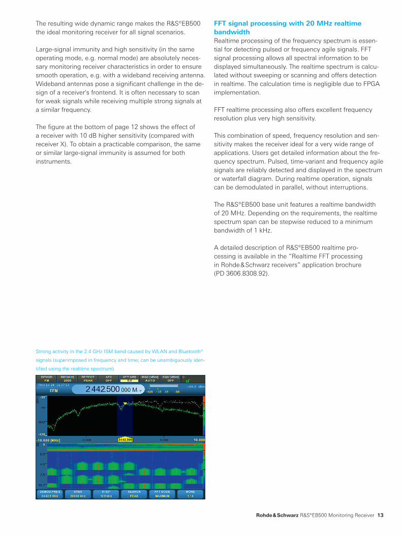
Strong activity in the 2.4 GHz ISM band caused by WLAN and Bluetooth®
signals (superimposed in frequency and time; can be unambiguously iden-
tified using the realtime spectrum).
The resulting wide dynamic range makes the R&S®EB500 the ideal monitoring receiver for all signal scenarios.
Large-signal immunity and high sensitivity (in the same operating mode, e.g. normal mode) are absolutely neces-sary monitoring receiver characteristics in order to ensure smooth operation, e.g. with a wideband receiving antenna. Wideband antennas pose a significant challenge in the de-sign of a receiver's frontend. It is often necessary to scan for weak signals while receiving multiple strong signals at a similar frequency.
The figure at the bottom of page 12 shows the effect of a receiver with 10 dB higher sensitivity (compared with receiver X). To obtain a practicable comparison, the same or similar large-signal immunity is assumed for both instruments.
EB500_bro_en_5214-3800-12.indd 13 16.04.2015 09:35:50
14
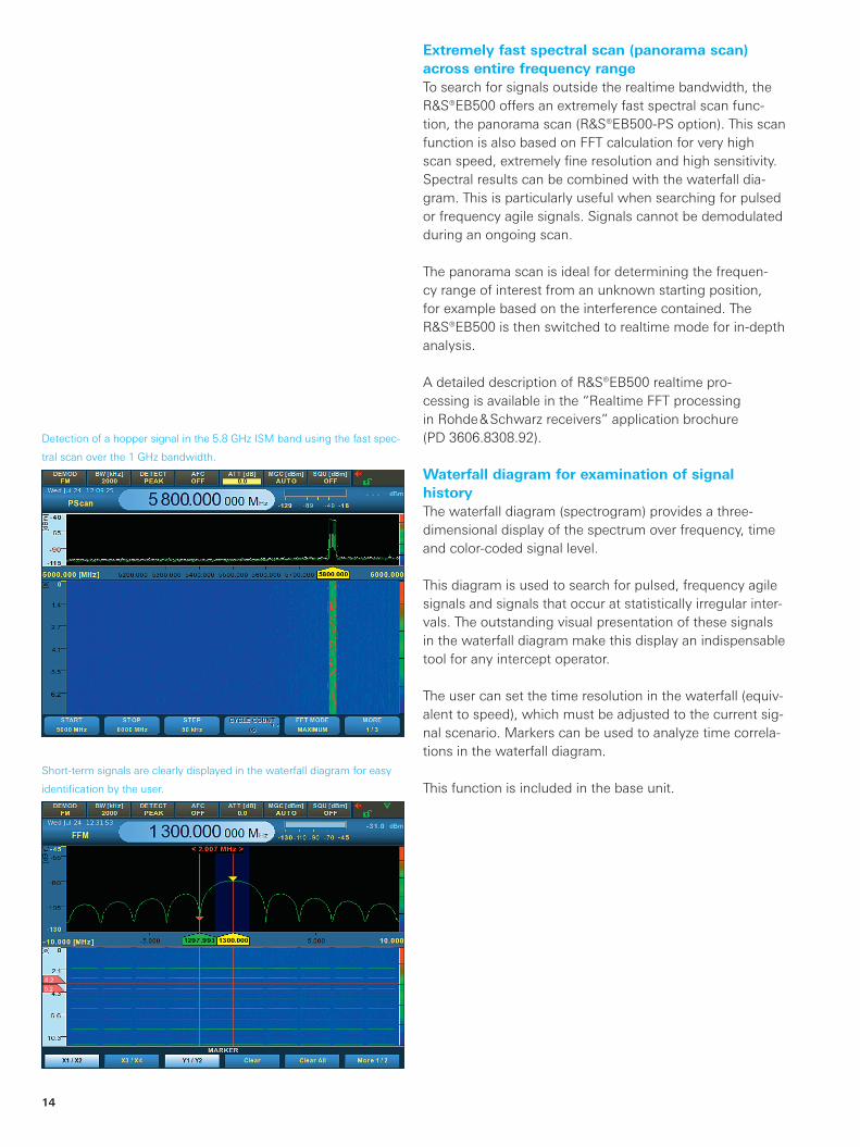
Extremely fast spectral scan (panorama scan) across entire frequency rangeTo search for signals outside the realtime bandwidth, the R&S®EB500 offers an extremely fast spectral scan func-tion, the panorama scan (R&S®EB500-PS option). This scan function is also based on FFT calculation for very high scan speed, extremely fine resolution and high sensitivity. Spectral results can be combined with the waterfall dia-gram. This is particularly useful when searching for pulsed or frequency agile signals. Signals cannot be demodulated during an ongoing scan.
The panorama scan is ideal for determining the frequen-cy range of interest from an unknown starting position, for example based on the interference contained. The R&S®EB500 is then switched to realtime mode for in-depth analysis.
A detailed description of R&S®EB500 realtime pro-cessing is available in the “Realtime FFT processing in Rohde & Schwarz receivers” application brochure (PD 3606.8308.92).
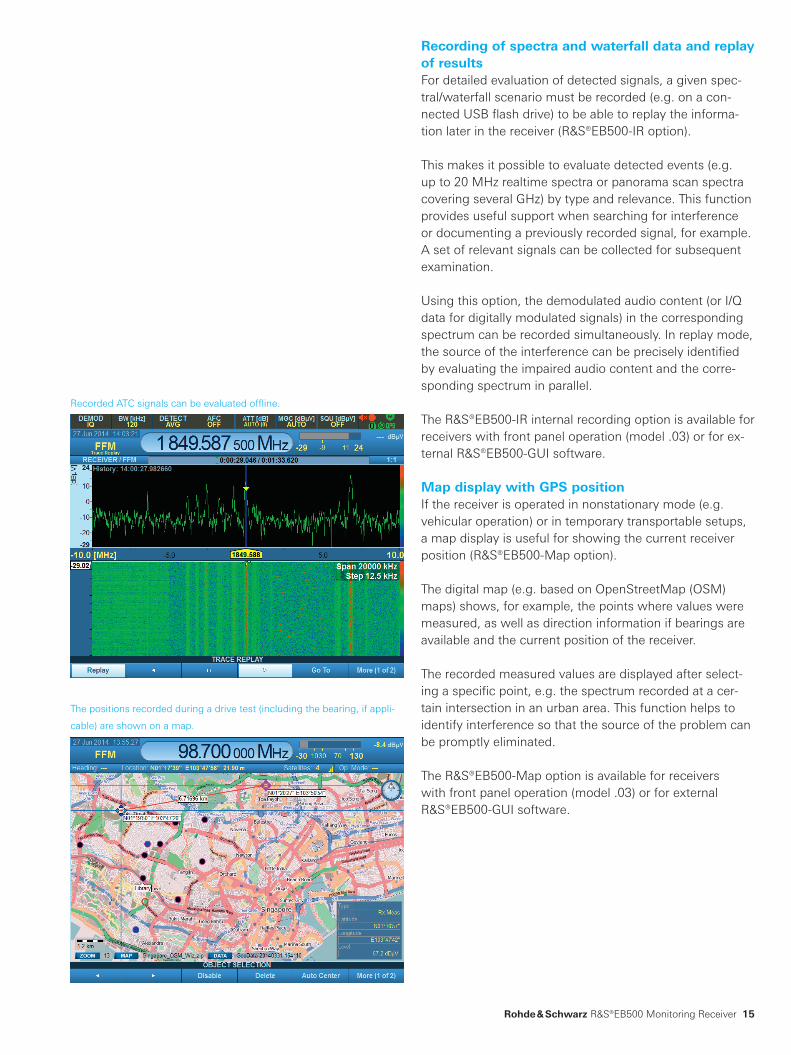
Waterfall diagram for examination of signal historyThe waterfall diagram (spectrogram) provides a three-dimensional display of the spectrum over frequency, time and color-coded signal level.
This diagram is used to search for pulsed, frequency agile signals and signals that occur at statistically irregular inter-vals. The outstanding visual presentation of these signals in the waterfall diagram make this display an indispensable tool for any intercept operator.
The user can set the time resolution in the waterfall (equiv-alent to speed), which must be adjusted to the current sig-nal scenario. Markers can be used to analyze time correla-tions in the waterfall diagram.
This function is included in the base unit.
Detection of a hopper signal in the 5.8 GHz ISM band using the fast spec-
tral scan over the 1 GHz bandwidth.
Short-term signals are clearly displayed in the waterfall diagram for easy
identification by the user.
EB500_bro_en_5214-3800-12.indd 14 16.04.2015 09:35:51
Rohde & Schwarz R&S®EB500 Monitoring Receiver 15
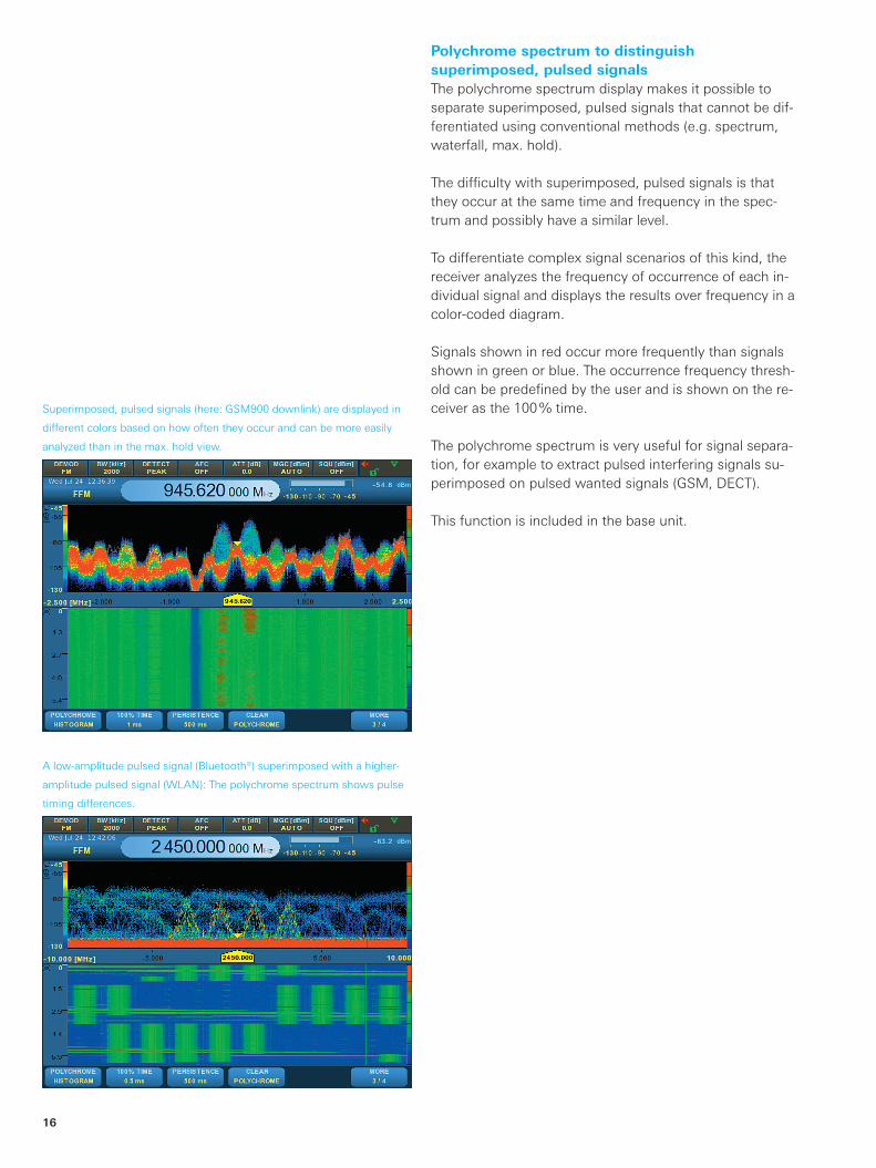
Recording of spectra and waterfall data and replay of resultsFor detailed evaluation of detected signals, a given spec-tral/waterfall scenario must be recorded (e.g. on a con-nected USB flash drive) to be able to replay the informa-tion later in the receiver (R&S®EB500-IR option).
This makes it possible to evaluate detected events (e.g. up to 20 MHz realtime spectra or panorama scan spectra covering several GHz) by type and relevance. This function provides useful support when searching for interference or documenting a previously recorded signal, for example. A set of relevant signals can be collected for subsequent examination.
Using this option, the demodulated audio content (or I/Q data for digitally modulated signals) in the corresponding spectrum can be recorded simultaneously. In replay mode, the source of the interference can be precisely identified by evaluating the impaired audio content and the corre-sponding spectrum in parallel.
The R&S®EB500-IR internal recording option is available for receivers with front panel operation (model .03) or for ex-ternal R&S®EB500-GUI software.
Map display with GPS positionIf the receiver is operated in nonstationary mode (e.g. vehicular operation) or in temporary transportable setups, a map display is useful for showing the current receiver position (R&S®EB500-Map option).
The digital map (e.g. based on OpenStreetMap (OSM) maps) shows, for example, the points where values were measured, as well as direction information if bearings are available and the current position of the receiver.
The recorded measured values are displayed after select-ing a specific point, e.g. the spectrum recorded at a cer-tain intersection in an urban area. This function helps to identify interference so that the source of the problem can be promptly eliminated.
The R&S®EB500-Map option is available for receivers with front panel operation (model .03) or for external R&S®EB500-GUI software.
Recorded ATC signals can be evaluated offline.
The positions recorded during a drive test (including the bearing, if appli-
cable) are shown on a map.
EB500_bro_en_5214-3800-12.indd 15 16.04.2015 09:35:51
16
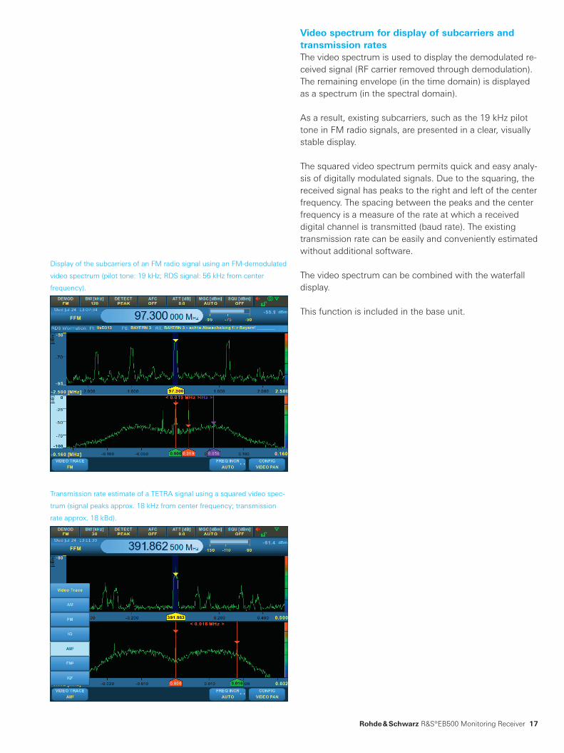
Polychrome spectrum to distinguish superimposed, pulsed signalsThe polychrome spectrum display makes it possible to separate superimposed, pulsed signals that cannot be dif-ferentiated using conventional methods (e.g. spectrum, waterfall, max. hold).
The difficulty with superimposed, pulsed signals is that they occur at the same time and frequency in the spec-trum and possibly have a similar level.
To differentiate complex signal scenarios of this kind, the receiver analyzes the frequency of occurrence of each in-dividual signal and displays the results over frequency in a color-coded diagram.
Signals shown in red occur more frequently than signals shown in green or blue. The occurrence frequency thresh-old can be predefined by the user and is shown on the re-ceiver as the 100 % time.
The polychrome spectrum is very useful for signal separa-tion, for example to extract pulsed interfering signals su-perimposed on pulsed wanted signals (GSM, DECT).
This function is included in the base unit.
Superimposed, pulsed signals (here: GSM900 downlink) are displayed in
different colors based on how often they occur and can be more easily
analyzed than in the max. hold view.
A low-amplitude pulsed signal (Bluetooth®) superimposed with a higher-
amplitude pulsed signal (WLAN): The polychrome spectrum shows pulse
timing differences.
EB500_bro_en_5214-3800-12.indd 16 16.04.2015 09:35:51
Rohde & Schwarz R&S®EB500 Monitoring Receiver 17
Video spectrum for display of subcarriers and transmission ratesThe video spectrum is used to display the demodulated re-ceived signal (RF carrier removed through demodulation). The remaining envelope (in the time domain) is displayed as a spectrum (in the spectral domain).
As a result, existing subcarriers, such as the 19 kHz pilot tone in FM radio signals, are presented in a clear, visually stable display.
The squared video spectrum permits quick and easy analy-sis of digitally modulated signals. Due to the squaring, the received signal has peaks to the right and left of the center frequency. The spacing between the peaks and the center frequency is a measure of the rate at which a received digital channel is transmitted (baud rate). The existing transmission rate can be easily and conveniently estimated without additional software.
The video spectrum can be combined with the waterfall display.
This function is included in the base unit.
Transmission rate estimate of a TETRA signal using a squared video spec-
trum (signal peaks approx. 18 kHz from center frequency; transmission
rate approx. 18 kBd).
Display of the subcarriers of an FM radio signal using an FM- demodulated
video spectrum (pilot tone: 19 kHz; RDS signal: 56 kHz from center
frequency).
EB500_bro_en_5214-3800-12.indd 17 16.04.2015 09:35:52

Display and LANIF spectrum
Digital audiovia LAN
I/Q data via LAN
Clear/write
Analog audio
IF3
Demodulationbandwidths100 Hz to 5 MHz
DDC
IF spectrum1 kHz to 20 MHz
DDC
Display and LAN
4096 points
16 bit
HF direct
IF panorama path
Demodulation path
Video spectrum
Video/IF analog output
16 bit
AGC
MGC
Demod.
16 bit
A
D
A
D
ITU measurement
Average
Min.hold
Max.hold
Fast
Peak
RMS
Average
Level measurement
A
D
Lowpass filter
FFT
ABS
Digital upconverter
18
Parallel signal processing permits users to simultaneously work with different bandwidth settings: wideband for a spectral overview and narrowband for demodulation and level measurements of a specific signal within the realtime bandwidth.
The center frequency of the realtime spectrum and de-modulator/level detector can be set independently of each other. Demodulation will only work if the frequency of the signal of interest is within the selected realtime spectrum.
Simplified diagram of digital signal processing in the base unit with the HF option
Parallel signal processing of spectral path and demodulation pathAfter A/D conversion of the received signal, the R&S®EB500 splits up signal processing into two paral-lel paths: the spectral path and the demodulation path or level measurement path.
As a result, demodulation and level measurements on signals within the realtime spectrum can be performed simultaneously and while being displayed in the realtime spectrum.
Audio signals are demodulated with interference-free audi-ble content since the R&S®EB500 does not need to switch between spectral and audio processing.
A seamless I/Q data stream is available for I/Q baseband demodulation – a vital processing step for subsequent sig-nal analysis with analysis software.
EB500_bro_en_5214-3800-12.indd 18 16.04.2015 09:35:52

Rohde & Schwarz R&S®EB500 Monitoring Receiver 19
Level measurements with “real” wideband detectorThe level of received signals is measured using a “real” wideband detector instead of the calculated FFT spectrum. Results are no longer corrupted due to FFT windowing, and it is no longer necessary to postprocess the level value (e.g. using a correction table).
The detector processes signals extremely fast, and even the signal levels of short-term pulses (less than a few hun-dred nanoseconds) can be accurately measured.
The high measurement bandwidth of up to 20 MHz is ideal for measuring the signal level of modern, digitally modu-lated signals, such as: ❙ DVB-T (approx. 8 MHz) ❙ LTE (up to 20 MHz)
Frequency scan and memory scan for audio demodulation on changing channelsThe frequency scan (FScan) and memory scan (MScan) modes included in the base unit can be used to check if certain radio services are occupied (level exceeds squelch) and, if emissions are detected, to dwell on this channel for a preset period of time, for example to output demodu-lated audio information.
The frequency scan mode should be used to scan radio services with specific parameters, e.g. ATC radio bands with fixed channel spacing, bandwidth and demodulation mode.
Due to its flexibly parameterized memory locations, the memory scan is ideal for scanning several different radio services (e.g. ATC, PTT) in a single scan. Demodulation pa-rameters and channel spacing are variably programmable.
Both scan modes allow users to conveniently search for active signals that are expected to occur in quick succes-sion on different channels, and ensure that audio content is quickly available.
Uncorrupted level measurement of a wideband LTE signal using the
wideband RMS detector.
For audio demodulation, the ATC radio band is examined in 25 kHz steps
to detect signals that exceed the squelch level.
EB500_bro_en_5214-3800-12.indd 19 16.04.2015 09:35:52
20
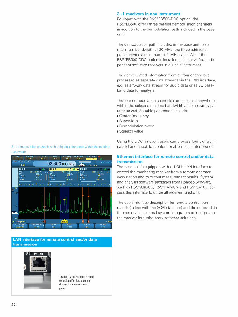
3+1 receivers in one instrumentEquipped with the R&S®EB500-DDC option, the R&S®EB500 offers three parallel demodulation channels in addition to the demodulation path included in the base unit.
The demodulation path included in the base unit has a maximum bandwidth of 20 MHz; the three additional paths provide a maximum of 1 MHz each. When the R&S®EB500-DDC option is installed, users have four inde-pendent software receivers in a single instrument.
The demodulated information from all four channels is processed as separate data streams via the LAN interface, e.g. as a *.wav data stream for audio data or as I/Q base-band data for analysis.
The four demodulation channels can be placed anywhere within the selected realtime bandwidth and separately pa-rameterized. Settable parameters include: ❙ Center frequency ❙ Bandwidth ❙ Demodulation mode ❙ Squelch value
Using the DDC function, users can process four signals in parallel and check for content or absence of interference.
Ethernet interface for remote control and/or data transmissionThe base unit is equipped with a 1 Gbit LAN interface to control the monitoring receiver from a remote operator workstation and to output measurement results. System and analysis software packages from Rohde & Schwarz, such as R&S®ARGUS, R&S®RAMON and R&S®CA100, ac-cess this interface to utilize all receiver functions.
The open interface description for remote control com-mands (in line with the SCPI standard) and the output data formats enable external system integrators to incorporate the receiver into third-party software solutions.
3+1 demodulation channels with different parameters within the realtime
bandwidth.
1 Gbit LAN interface for remote control and/or data transmis-sion on the receiver's rear panel
LAN interface for remote control and/or data transmission
EB500_bro_en_5214-3800-12.indd 20 16.04.2015 09:35:52

Rohde & Schwarz R&S®EB500 Monitoring Receiver 21
Receiver remote control and data recordingThe base unit comes with the R&S®EB500-Control soft-ware package for remotely controlling the receiver via the 1 Gbit LAN interface. All functions are available, from tun-ing the receiver to a center frequency and parameterizing the realtime spectrum to starting the fast spectral scan. R&S®EB500-Control records all results, including spectra, waterfall, demodulated audio information and I/Q base-band data, to the remote controller's hard disk.
It is possible to replay recorded data for offline analysis (I/Q data processing, e.g. with R&S®CA100 or MATLAB®).
The R&S®EB500-Control software package provides a point-to-point connection between a PC and a receiver. The R&S®RAMON software extends the functionality to create a system solution (e.g. connecting several users to one receiver).
Realtime spectrum and waterfall display of a radar signal from Singapore airport.
EB500_bro_en_5214-3800-12.indd 21 16.04.2015 09:35:53

22
ITU-compliant measurements in the receiverThe R&S®EB500-IM option enables ITU-compliant mea-surements of signal parameters for AM, FM and PM-modulated signals. The modulation index, occupied bandwidth and phase deviation can be determined, for example. The minimum, maximum and average values over a user- defined measurement period are displayed. The R&S®EB500-IM option covers the following ITU recommendations: ❙ ITU-R SM.377 (frequency and frequency offset measurements)
❙ ITU-R SM.378 (field strength measurements) ❙ ITU-R SM.328 (bandwidth measurements) ❙ ITU-R SM.443 (bandwidth measurements) ❙ ITU-R SM.1880 (determination of spectral occupancy, with remote control PC and R&S®ARGUS software package)
For offline measurement of digitally modulated signals in line with ITU-R SM.1600, the R&S®CA100IS option can be added to the R&S®CA100 software solution (requires an additional PC).
The R&S®EB500 fulfills the following ITU hardware recommendations: ❙ ITU-R SM.1836 (measurements of IF filter edge steepness)
❙ ITU-R SM.1837 (IP3 measurements) ❙ ITU-R SM.1838 (noise figure measurements) ❙ ITU-R SM.1840 (sensitivity measurements)
Modulation and bandwidth measurement results at a glance.
Offline measurement of a Digital Radio Mondiale (DRM) signal in line with
ITU-R SM.1600.
EB500_bro_en_5214-3800-12.indd 22 16.04.2015 09:35:53
¸EB500
¸EB500 ¸EB500
LAN
NTP server
Rohde & Schwarz R&S®EB500 Monitoring Receiver 23
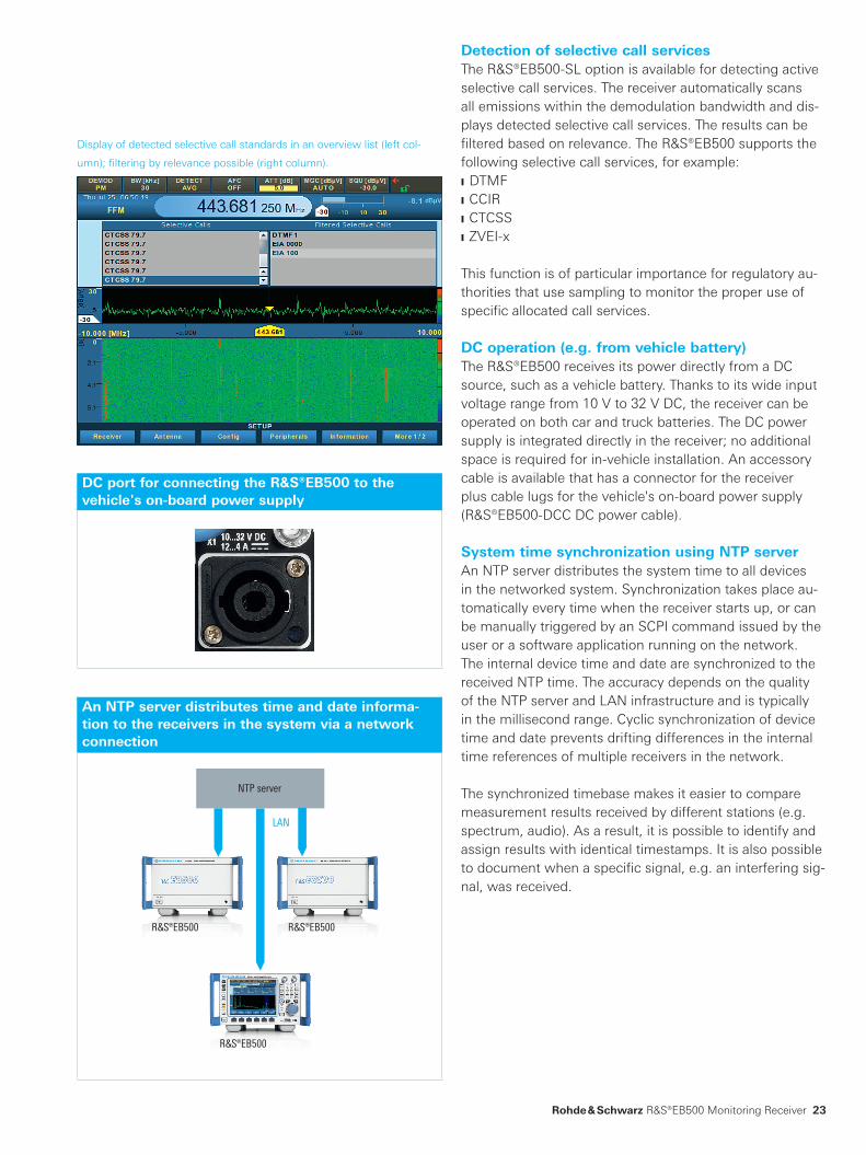
Detection of selective call servicesThe R&S®EB500-SL option is available for detecting active selective call services. The receiver automatically scans all emissions within the demodulation bandwidth and dis-plays detected selective call services. The results can be filtered based on relevance. The R&S®EB500 supports the following selective call services, for example: ❙ DTMF ❙ CCIR ❙ CTCSS ❙ ZVEI-x
This function is of particular importance for regulatory au-thorities that use sampling to monitor the proper use of specific allocated call services.
DC operation (e.g. from vehicle battery)The R&S®EB500 receives its power directly from a DC source, such as a vehicle battery. Thanks to its wide input voltage range from 10 V to 32 V DC, the receiver can be operated on both car and truck batteries. The DC power supply is integrated directly in the receiver; no additional space is required for in-vehicle installation. An accessory cable is available that has a connector for the receiver plus cable lugs for the vehicle's on-board power supply (R&S®EB500-DCC DC power cable).
System time synchronization using NTP serverAn NTP server distributes the system time to all devices in the networked system. Synchronization takes place au-tomatically every time when the receiver starts up, or can be manually triggered by an SCPI command issued by the user or a software application running on the network. The internal device time and date are synchronized to the received NTP time. The accuracy depends on the quality of the NTP server and LAN infrastructure and is typically in the millisecond range. Cyclic synchronization of device time and date prevents drifting differences in the internal time references of multiple receivers in the network.
The synchronized timebase makes it easier to compare measurement results received by different stations (e.g. spectrum, audio). As a result, it is possible to identify and assign results with identical timestamps. It is also possible to document when a specific signal, e.g. an interfering sig-nal, was received.
Display of detected selective call standards in an overview list (left col-
umn); filtering by relevance possible (right column).
DC port for connecting the R&S®EB500 to the vehicle's on-board power supply
An NTP server distributes time and date informa-tion to the receivers in the system via a network connection
EB500_bro_en_5214-3800-12.indd 23 16.04.2015 09:35:54
24
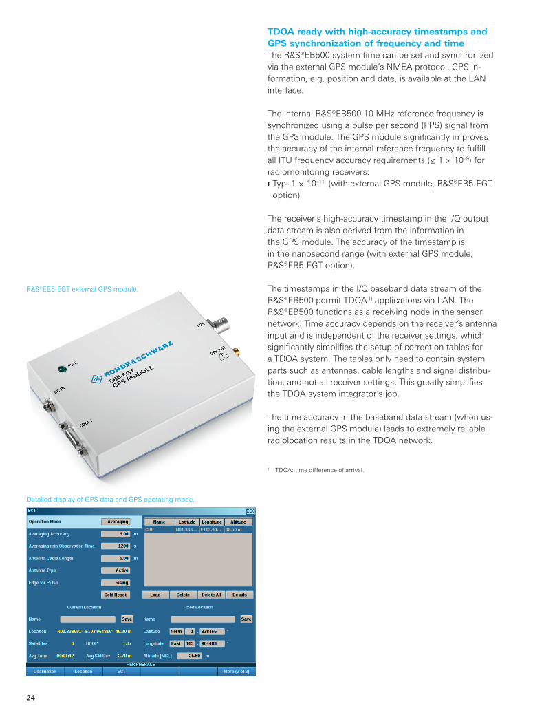
TDOA ready with high-accuracy timestamps and GPS synchronization of frequency and timeThe R&S®EB500 system time can be set and synchronized via the external GPS module’s NMEA protocol. GPS in-formation, e.g. position and date, is available at the LAN interface.
The internal R&S®EB500 10 MHz reference frequency is synchronized using a pulse per second (PPS) signal from the GPS module. The GPS module significantly improves the accuracy of the internal reference frequency to fulfill all ITU frequency accuracy requirements (≤ 1 × 10⁻⁹) for radiomonitoring receivers: ❙ Typ. 1 × 10–11 (with external GPS module, R&S®EB5-EGT option)
The receiver’s high-accuracy timestamp in the I/Q output data stream is also derived from the information in the GPS module. The accuracy of the timestamp is in the nanosecond range (with external GPS module, R&S®EB5-EGT option).
The timestamps in the I/Q baseband data stream of the R&S®EB500 permit TDOA 1) applications via LAN. The R&S®EB500 functions as a receiving node in the sensor network. Time accuracy depends on the receiver’s antenna input and is independent of the receiver settings, which significantly simplifies the setup of correction tables for a TDOA system. The tables only need to contain system parts such as antennas, cable lengths and signal distribu-tion, and not all receiver settings. This greatly simplifies the TDOA system integrator’s job.
The time accuracy in the baseband data stream (when us-ing the external GPS module) leads to extremely reliable radiolocation results in the TDOA network.
1) TDOA: time difference of arrival.
Detailed display of GPS data and GPS operating mode.
R&S®EB5-EGT external GPS module.
EB500_bro_en_5214-3800-12.indd 24 16.04.2015 09:35:55
Rohde & Schwarz R&S®EB500 Monitoring Receiver 25
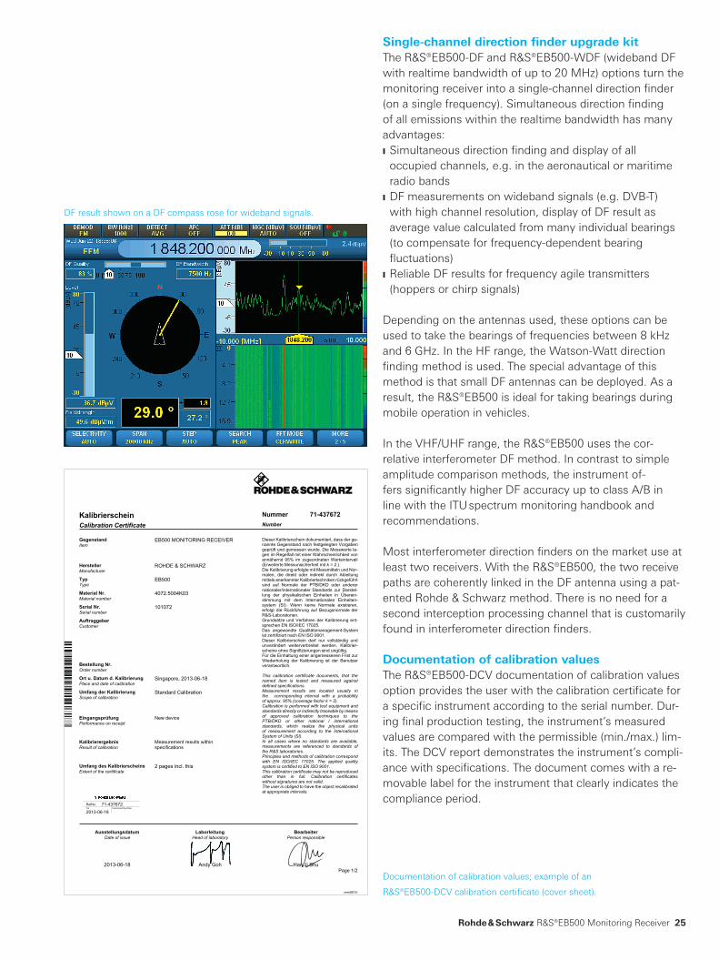
Single-channel direction finder upgrade kitThe R&S®EB500-DF and R&S®EB500-WDF (wideband DF with realtime bandwidth of up to 20 MHz) options turn the monitoring receiver into a single-channel direction finder (on a single frequency). Simultaneous direction finding of all emissions within the realtime bandwidth has many advantages: ❙ Simultaneous direction finding and display of all occupied channels, e.g. in the aeronautical or maritime radio bands
❙ DF measurements on wideband signals (e.g. DVB-T) with high channel resolution, display of DF result as average value calculated from many individual bearings (to compensate for frequency-dependent bearing fluctuations)
❙ Reliable DF results for frequency agile transmitters (hoppers or chirp signals)
Depending on the antennas used, these options can be used to take the bearings of frequencies between 8 kHz and 6 GHz. In the HF range, the Watson-Watt direction finding method is used. The special advantage of this method is that small DF antennas can be deployed. As a result, the R&S®EB500 is ideal for taking bearings during mobile operation in vehicles.
In the VHF/UHF range, the R&S®EB500 uses the cor-relative interferometer DF method. In contrast to simple amplitude comparison methods, the instrument of-fers significantly higher DF accuracy up to class A/B in line with the ITU spectrum monitoring handbook and recommendations.
Most interferometer direction finders on the market use at least two receivers. With the R&S®EB500, the two receive paths are coherently linked in the DF antenna using a pat-ented Rohde & Schwarz method. There is no need for a second interception processing channel that is customarily found in interferometer direction finders.
Documentation of calibration valuesThe R&S®EB500-DCV documentation of calibration values option provides the user with the calibration certificate for a specific instrument according to the serial number. Dur-ing final production testing, the instrument’s measured values are compared with the permissible (min./max.) lim-its. The DCV report demonstrates the instrument’s compli-ance with specifications. The document comes with a re-movable label for the instrument that clearly indicates the compliance period.
DF result shown on a DF compass rose for wideband signals.
Documentation of calibration values; example of an
R&S®EB500-DCV calibration certificate (cover sheet).
Kalibrierschein Nummer 71-437672Calibration Certificate Number
GegenstandItem
EB500 MONITORING RECEIVER
HerstellerManufacturer
ROHDE & SCHWARZ
TypType
EB500
Material Nr.Material number
4072.5004K03
Serial Nr.Serial number
101072
AuftraggeberCustomer
Bestellung Nr.Order number
Ort u. Datum d. KalibrierungPlace and date of calibration
Singapore, 2013-06-18
Umfang der KalibrierungScope of calibration
Standard Calibration
EingangsprüfungPerformance on receipt
New device
KalibrierergebnisResult of calibration
Measurement results withinspecifications
Umfang des KalibrierscheinsExtent of the certificate
2 pages incl. this
RefNo. 71-437672Cal Customized Due Date
2013-06-18
Dieser Kalibrierschein dokumentiert, dass der ge-nannte Gegenstand nach festgelegten Vorgabengeprüft und gemessen wurde. Die Messwerte la-gen im Regelfall mit einer Wahrscheinlichkeit vonannähernd 95% im zugeordneten Werteintervall(Erweiterte Messunsicherheit mit k = 2 ).Die Kalibrierung erfolgte mit Messmitteln und Nor-malen, die direkt oder indirekt durch Ableitungmittels anerkannter Kalibriertechniken rückgeführtsind auf Normale der PTB/DKD oder anderernationaler/internationaler Standards zur Darstel-lung der physikalischen Einheiten in Überein-stimmung mit dem Internationalen Einheiten-system (SI). Wenn keine Normale existieren,erfolgt die Rückführung auf Bezugsnormale derR&S-Laboratorien.Grundsätze und Verfahren der Kalibrierung ent-sprechen EN ISO/IEC 17025.Das angewandte Qualitätsmanagement-Systemist zertifiziert nach EN ISO 9001.Dieser Kalibrierschein darf nur vollständig undunverändert weiterverbreitet werden. Kalibrier-scheine ohne Signifizierungen sind ungültig.Für die Einhaltung einer angemessenen Frist zurWiederholung der Kalibrierung ist der Benutzerverantwortlich.
This calibration certificate documents, that thenamed item is tested and measured againstdefined specifications.Measurement results are located usually inthe corresponding interval with a probabilityof approx. 95% (coverage factor k = 2).Calibration is performed with test equipment andstandards directly or indirectly traceable by meansof approved calibration techniques to thePTB/DKD or other national / internationalstandards, which realize the physical unitsof measurement according to the InternationalSystem of Units (SI).In all cases where no standards are available,measurements are referenced to standards ofthe R&S laboratories.Principles and methods of calibration correspondwith EN ISO/IEC 17025. The applied qualitysystem is certified to EN ISO 9001.This calibration certificate may not be reproducedother than in full. Calibration certificateswithout signatures are not valid.The user is obliged to have the object recalibratedat appropriate intervals.
Ausstellungsdatum Laborleitung BearbeiterDate of issue Head of laboratory Person responsible
2013-06-18 Andy Goh Han Ji ShuPage 1/2
vers9815/
EB500_bro_en_5214-3800-12.indd 25 16.04.2015 09:35:56

26
Specifications in briefSpecifications in briefFrequency
Frequency range, receive mode base unit 20 MHz to 3.6 GHz
with R&S®EB500-HF option 8 kHz to 3.6 GHz
with R&S®EB500-FE option 20 MHz to 6 GHz
with R&S®EB500-HF and R&S®EB500-FE options 8 kHz to 6 GHz
IF bandwidths
Bandwidth demodulation, level and offset measurement(3 dB bandwidth), 34 filters
100/150/300/600 Hz, 1/1.5/2.1/2.4/2.7/3.1/4/4.8/6/9/12/15/30/50/120/150/250/300/500/800 kHz,1/1.25/1.5/2/5/8/10/12.5/15/20 MHz
Demodulation
Demodulation modes all IF bandwidths AM, FM, φM, pulse, ISB, I/Q
IF bandwidths ≤ 8 kHz LSB, USB, CW, ISB
Realtime spectrum (IF panorama)
FFT spectrum gap-free, dynamically overlapping FFT
operating mode: automatic or variable with selectable frequency resolution0.625/1.25/2.5/3.125/6.25/12.5/25/31.25/50/62.5/100/125/200/250/312.5/500/ 625 Hz,1/1.25/2/2.5/3.125/5/6.25/8.333/10/12.5/20/25/50/100/200/500 kHz,1 MHz, 2 MHz
Spectrum span base unit 1/2/5/10/20/50/100/200/500 kHz, 1/2/5/10/20 MHz
Spectrum display clear/write, average, max. hold, min. hold, histogram, pulse
Scan characteristics
Memory scan 10 000 programmable memory locations
speed up to 500 channels/s
Frequency scan user-selectable start/stop frequency and step size
speed up to 500 channels/s
Fast spectral scan (panorama scan) with R&S®EB500-PS option spectral scan with user-selectable start/stop frequency, step size (bin):100/125/200/250/500/625 Hz,1/1.25/2/2.5/3.125/5/6.25/8.333/10/12.5/20/25/50/100/200/500 kHz,1 MHz, 2 MHz
speed up to 75 GHz/s (in-band)
For data sheet, see PD 5214.3800.22 and www.rohde-schwarz.com
EB500_bro_en_5214-3800-12.indd 26 16.04.2015 09:35:56

Rohde & Schwarz R&S®EB500 Monitoring Receiver 27
Ordering informationDesignation Type Order No.Monitoring Receiver, without front panel control R&S®EB500 4072.5004.02
Monitoring Receiver, with front panel control R&S®EB500 4072.5004.03
Documentation of Calibration Values R&S®EB500-DCV 4072.8403.02
Options
HF Frequency Range Extension, 8 kHz to 32 MHz R&S®EB500-HF 4072.8003.02
SHF Frequency Range Extension, 3.6 GHz to 6 GHz R&S®EB500-FE 4072.9300.02
Panorama Scan R&S®EB500-PS 4072.9200.02
Internal Recording R&S®EB500-IR 4072.9551.02
Map Display R&S®EB500-Map 4072.9451.02
ITU Measurement Software R&S®EB500-IM 4072.9100.02
Selective Call Analysis R&S®EB500-SL 4072.9800.02
Digital Downconverter R&S®EB500-DDC 4072.9500.02
Direction Finder Upgrade Kit R&S®EB500-DF 4072.9400.02
Wideband Direction Finding R&S®EB500-WDF 4072.9651.02
DF Error Correction R&S®EB500-COR 4072.9600.02
External GPS Module R&S®EB5-EGT 4073.2009.02
Recommended extras
19" Rack Adapter (2 × R&S®EB500 side by side) R&S®ZZA-T04 1109.4187.00
19" Rack Adapter (1 × R&S®EB500 + 1 × blind plate) R&S®ZZA-T02 1109.4164.00
DC Power Cable R&S®EB500-DCC 4072.7036.00
Service optionsExtended Warranty, one year R&S®WE1 Please contact your lo-
cal Rohde & Schwarz sales representative.
Extended Warranty, two years R&S®WE2
Extended Warranty, three years R&S®WE3
Extended Warranty, four years R&S®WE4
Extended Warranty with Calibration Coverage, one year R&S®CW1
Extended Warranty with Calibration Coverage, two years R&S®CW2
Extended Warranty with Calibration Coverage, three years R&S®CW3
Extended Warranty with Calibration Coverage, four years R&S®CW4
The Bluetooth® word mark and logos are registered trademarks owned by Bluetooth SIG, Inc. and any use of such marks by Rohde & Schwarz is under license.
Your local Rohde & Schwarz expert will help you determine the optimum solution for your requirements.To find your nearest Rohde & Schwarz representative, visit www.sales.rohde-schwarz.com
EB500_bro_en_5214-3800-12.indd 27 16.04.2015 09:35:56

R&S® is a registered trademark of Rohde & Schwarz GmbH & Co. KG
Trade names are trademarks of the owners
PD 5214.3800.12 | Version 05.00 | April 2015 (sk)
R&S®EB500 Monitoring Receiver
Data without tolerance limits is not binding | Subject to change
© 2010 - 2015 Rohde & Schwarz GmbH & Co. KG | 81671 Munich, Germany
Service that adds value❙ Worldwide ❙ Local and personalized❙ Customized and flexible❙ Uncompromising quality ❙ Long-term dependability
5214
.380
0.12
05.
00 P
DP
1 e
n
About Rohde & SchwarzThe Rohde & Schwarz electronics group is a leading supplier of solutions in the fields of test and measurement, broadcast and media, secure communications, cybersecurity, and radiomonitor ing and radiolocation. Founded more than 80 years ago, this independent global company has an extensive sales network and is present in more than 70 countries. The company is headquartered in Munich, Germany.
Sustainable product design ❙ Environmental compatibility and ecofootprint ❙ Energy efficiency and low emissions ❙ Longevity and optimized total cost of ownership
Certified Environmental Management
ISO 14001Certified Quality Management
ISO 9001
Regional contact ❙ Europe, Africa, Middle East | +49 89 4129 12345 customersupport@rohdeschwarz.com
❙ North America | 1 888 TEST RSA (1 888 837 87 72) [email protected]schwarz.com
❙ Latin America | +1 410 910 79 88 customersupport.la@rohdeschwarz.com
❙ Asia Pacific | +65 65 13 04 88 customersupport.asia@rohdeschwarz.com
❙ China | +86 800 810 82 28 | +86 400 650 58 96 customersupport.china@rohdeschwarz.com
Rohde & Schwarz GmbH & Co. KGwww.rohdeschwarz.com
5214380012
EB500_bro_en_5214-3800-12.indd 28 16.04.2015 09:35:56