RS232 GPRS DATA GATEWAY V1 - Automation Research …automationresearchlabs.com/document/RS232 GPRS...
17
RS232 GPRS DATA GATEWAY V1.20 KUROLIKAR AUTOMATION RESEARCH LABS PVT LTD 1 User manual RS232 GPRS DATA GATEWAY V1.20 UASAGE NOTICE This software / document / material are property of Kurolikar Automation Research Labs (KARL PL) Pvt Ltd. It has been provided for the exclusive use of customers for the products of KARL PL. It must not be copied, saved or duplicated in full or in part in any form without the written permission of KARL PL. Unauthorized copying, duplication or reproduction of this material is restricted and may attract severe legal penalties. The specifications and features mentioned in this document are available at the time this document was prepared. Utmost care has been taken to maintain accuracy and consistency of the information. However KARL PL does not guarantee this document to be free from errors and use of the information is at sole responsibility of the user. KARL PL reserves the right to change or modify this document at any time without prior notice.
Transcript of RS232 GPRS DATA GATEWAY V1 - Automation Research …automationresearchlabs.com/document/RS232 GPRS...

RS232 GPRS DATA GATEWAY V1.20 KUROLIKAR AUTOMATION RESEARCH LABS PVT LTD
1
User manual
RS232 GPRS DATA GATEWAY
V1.20
UASAGE NOTICE
This software / document / material are property of Kurolikar Automation Research Labs
(KARL PL) Pvt Ltd. It has been provided for the exclusive use of customers for the products
of KARL PL. It must not be copied, saved or duplicated in full or in part in any form without
the written permission of KARL PL. Unauthorized copying, duplication or reproduction of
this material is restricted and may attract severe legal penalties.
The specifications and features mentioned in this document are available at the time this
document was prepared. Utmost care has been taken to maintain accuracy and consistency
of the information. However KARL PL does not guarantee this document to be free from
errors and use of the information is at sole responsibility of the user. KARL PL reserves the
right to change or modify this document at any time without prior notice.

RS232 GPRS DATA GATEWAY V1.20 KUROLIKAR AUTOMATION RESEARCH LABS PVT LTD
2
INDEX
1. INTRODUCTION
a. GSM / GPRS features
b. Data monitoring features
c. Applications
2. GETTING STARTED
a. String format of uploaded data
b. Connection pin-out
c. Wiring diagram
3. MODEM CONFIGURATION
a. Configuration commands
b. Getting information from data logger modem
4. APPENDIX
a. Troubleshooting notes
5. WARRANTY STATEMENT

RS232 GPRS DATA GATEWAY V1.20 KUROLIKAR AUTOMATION RESEARCH LABS PVT LTD
3
INTRODUCTION
Product: Data logger modem
Data collection interface: Serial RS232
Data uploading interface: TCP/IP over GPRS
Modem configuration and alerts: plain text SMS
The data logger modem gets information from connected device over RS232 bus and
sends tomapped server over GPRS. For reliable data uploading to server, the modem sends
data only if sufficient signal strength is available. It also implements retry of data upload
and packet based handshaking to make sure that every data packet issuccessfully delivered
to the server.
The data logger modem saves collected data samples temporarily in local memory and
send to GPRS server at predefined interval or when a predefined number of samples are
collected in memory. The internal memory is non-volatile and data is not lost even if
external power is lost.
‘Automation Research Labs’ manufactures different models of such modems. These
various models of modems are designed in such a way that a completely heterogeneous
system can be implemented. A single data acquisition system can consist of some single-
RTU modems, some multi-RTU modems, some data logger modems, some direct IO
modems and some plain GSM modems. This enables customers to choose the right modem
for their application and saves costs. This also enables the server side software developers
to write seamless interface libraries for parsing and saving the received data in database.
GSM/GPRS Features:
Based on Quectel quad band GSM/GPRS module. Supports TCP/IP Protocol. Quad band 850/900/1800/1900MHz. 3V SIM Card Slot. Works with off-the-shelf available 50E antenna. Aluminum casing with powder coating.
Data Monitoring Features:
RS232 serial interface with selectable baud rate to collect data from device
Can fetch data from device by acting as master if required. Means sends command to connected device to get data from it.
Delimited data samples are collected from the connected device
Can discard selective samples depending upon the configuration

RS232 GPRS DATA GATEWAY V1.20 KUROLIKAR AUTOMATION RESEARCH LABS PVT LTD
4
Modem device can be configured from anywhere using SMS
Can save samples of interest in internal non-volatile memory.
Up to 128Kbyte non-volatile memory for saving data locally.
Data read frequency, Destination IP address, and Destination phone number for SMS,diagnostic SMS configurable from predefined mobile number.
Handles all AT commands internally.No need to write AT commands in external device.
Transmits data to server over GPRS when strong GPRS signal is available. Acknowledgement can be enabled or disabled at user will.
Applications:
Energy meter monitoring.
Monitoring product data from PLC / SCADA systems.
Monitoring custom devices having serial communication interface
Material inspection device data collection systems
Many more…..
RS232 GPRS DATA GATEWAY V1.20 KUROLIKAR AUTOMATION RESEARCH LABS PVT LTD
5
GETTING STARTED
For product version 3.1 and lower, supported power supply range is 6VDC to12VDC.For product version 3.2 onwards, supported power supply range is 7.5VDC to 24VDC. Power source should be capable of sourcing minimum of 1A current.
Make sure to connect stable power supply to modem with specified polarity.
Wrong power supply connections (reverse polarity) for long duration may permanently damage modem.
Make sure that the SIMcard has enough memory space free to receive messages.
Make sure that the SIM card has GPRS and SMS services activated.
Supported service providers for GPRS are Airtel, Uninor, Idea, BSNL. (May work with other service providers but not tested for GPRS data connectivity) Product version 3.2 onward supports dynamically adding support for unknown SIM cards.
Communication settings are as below Baud rate: user settable
Start bit: 1
Data bits: 8 (LSB sent first)
Parity bit: None
Stop bit: 1
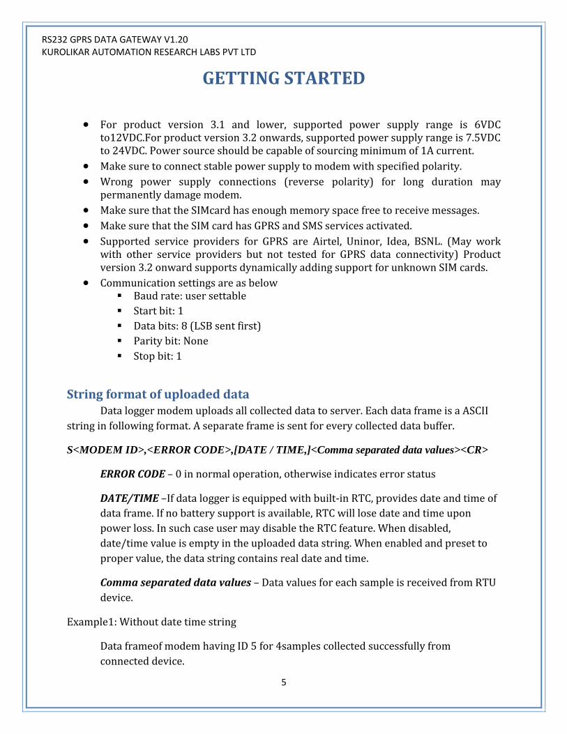
String format of uploaded data Data logger modem uploads all collected data to server. Each data frame is a ASCII
string in following format. A separate frame is sent for every collected data buffer.
S<MODEM ID>,<ERROR CODE>,[DATE / TIME,]<Comma separated data values><CR>
ERROR CODE – 0 in normal operation, otherwise indicates error status
DATE/TIME –If data logger is equipped with built-in RTC, provides date and time of
data frame. If no battery support is available, RTC will lose date and time upon
power loss. In such case user may disable the RTC feature. When disabled,
date/time value is empty in the uploaded data string. When enabled and preset to
proper value, the data string contains real date and time.
Comma separated data values – Data values for each sample is received from RTU
device.
Example1: Without date time string
Data frameof modem having ID 5 for 4samples collected successfully from
connected device.

RS232 GPRS DATA GATEWAY V1.20 KUROLIKAR AUTOMATION RESEARCH LABS PVT LTD
6
S05,<SPACE> ,5644,15,8851,2594<CR>
Example2: With date time string
Data frameof data logger ID 1 for 3samples read successfully from device.
S01,01/11/2013 14:45:32,8851,2594,640<CR>
Color notations:
Blue: Information source
Black: Date and time in dd/MM/yyyy HH:mm:ss format
Green: Data received from connected device
Brown: Termination character, ASCII code for CARRIAGE RETURN
Purple: singlespace
Connections pin-out: Modem has D sub miniature 9 pin female connector for signal interface and 2pin phoenix
two piece right angle screw terminal for power supply connections. Below are pin wise
details for both these connectors.
DB9 PIN
SIGNAL NAME (RS232)
1 NC 2 TXD 3 RXD 4 NC 5 GND 6 NC 7 NC 8 NC 9 NC
Case Connected to Ground
Table Terminology
NC: No internal connection. GND: Supply negative
Warning: Wrong connection or over voltage at any of the D type serial connector pin may permanently damage the modem.

RS232 GPRS DATA GATEWAY V1.20 KUROLIKAR AUTOMATION RESEARCH LABS PVT LTD
7
Wiring diagram:

RS232 GPRS DATA GATEWAY V1.20 KUROLIKAR AUTOMATION RESEARCH LABS PVT LTD
8
MODEMCONFIGURATION
Data loggermodem is fully configurable using SMS. Each setting that needs to be changed can be configured using a simple text SMS from a predefined number. The configuration commands are entertained from an authorized number only.Any configuration command received from unknown number is discarded.
Configuration commands
a. Setting IP address of a server for data uploading Modemsends all the collected data samples to configured IP address over
GPRS channel. The data uploading happens over TCP/IP hence require valid public IP address and free socket number on that server. User can configure both these settings using following SMS command.
SET<space>IP<space><Always 1>,<IP address of a server>,<TCP
socket number>
Note: A TCP server listening software must be continuously running on the server
to receive the data being sent by modem. Default socket number for communication is 2020 Make sure that entered Server IP is valid IP address accessible over public
network.
b. Setting APN User can configure the APN settings using following command.
SET<space>APN<space><entry index>,<name of service
provider>,<APN string for the SIM card service provider>
E.g. SET APN 1,Airtel,airtelgprs SET APN 2,!dea,internet
Modem supports up to 15 entries to be added for different type of SIM cards. Whenever new type of SIM card is used in the modem, the modem tries to find APN string for that SIM. If it is not available, GPRS connection cannot be established. Hence it is a mandatory step for using data uploading feature. Normally all common APN settings are available in the modem as factory setting.

RS232 GPRS DATA GATEWAY V1.20 KUROLIKAR AUTOMATION RESEARCH LABS PVT LTD
9
c. Setting Mobile Number Data logger configuration can be done by authorized user only. There are
typically two type users who can configure the modem.A master user is one who can configure the modem as well as can change number of own or other user. Another user is a regular user who can only configure the modem. Both these numbers can be updated using following commands
SET<space>MASTER<space><mobile number>
Regular user mobile number can be set using following SMS command.
SET<space>USER1NUM<space><mobile number>
Note: o Make sure that entered mobile number is valid number. o Mobile number is a 10 digit number. Country code should not be included.
d. Setting RTC Time This is optional feature. This command will work only if your product model
supports it.Time and date stamp appears in data string transmitted to server.User can set time and date using following SMS command. Time specified is in 24hour format.
SET<space>TIME<space><DD/MM/YYYY><space><HH:MM:SS>
Note: Single space cannot be replaced by multiple spaces.
e. Enable real time clock User can enable the real time clock using following command.
RTC<space>ENABLE
f. Disable real time clock User can disable the real time clock using following command.
RTC<space>DISABLE
g. Setting modem ID: This command sets unique identifier for every data logger modem. This way,
server software can uniquely identify the modemfrom which the data is being

RS232 GPRS DATA GATEWAY V1.20 KUROLIKAR AUTOMATION RESEARCH LABS PVT LTD
10
received. If the software can accept multiple client connection over TCP/IP, multiple
modems can connect to single server and send data to it.
User can set modemID using following SMS command
SET<space>DEVICEID<space><ModemID>
Note: o DEVICEID can be from 1 through 2000. o Default value for this setting is 1
h. Setting data saving scheme: The modem can be configured to skip some of the data samples if the
external device continuously sends data samples at relatively high rate. All the
samples received by the modemarenot saved directly to the memory. Instead,
modem can skip the number of data samples in between. The number of how many
data samples should be discarded can be set using this command. Maximium
allowed value for this setting is 100 and factory default setting is 0.
User can set number of samples to skip using following SMS command
SET<space>DSSCHM<space><Number of samples to skip>
e.g. SET DSSCHM 2
Modem will log every third data sample in internal memory. In another
words, after logging any data sample into local memory, two samples are
discarded.
e.g. SET DSSCHM 0
This will log all the data samples received without skipping any sample.
i. Setting data uploadingscheme: User can set Data Uploading scheme using following SMS command –
SET<space>UPSCHM<space><1or2>
1 = upload data samples at predefined interval. The time interval can be set in steps of minutes.
2 = uploading predefined number of data samples collected in memory. The number of data sample threshold can be set.

RS232 GPRS DATA GATEWAY V1.20 KUROLIKAR AUTOMATION RESEARCH LABS PVT LTD
11
Default upload scheme is ‘1’. Hence modem uploads data to TCP server at predefined interval. This time is settable. Refer subsequent sections for the command.
j. Setting data upload interval time: If data upload scheme 1 is selected, modem sends all collected data to server
at every configured interval time.This time is user selectable from 2minutes through
150minutes. Default interval time is 30minutes. In case of scheme ‘2’, this command
is redundant.
If user set data frequency greater than 150minutes, data logger sends data at default frequency of 150. If user set data frequency less than 2minute, modem sends data at default frequency of 2 minutes.
User can set data frequency using following SMS command
SET<space>DATAFREQ<space><Data Frequency>
k. Setting number of samples threshold: If data upload scheme 2 is selected, modem uploads data to serverwhen
predefined numbers of samples are collected in memory.Number of samples should
not be greater than 2000. Default value for this setting is 25. User must make sure
that the threshold set here does not cause memory overflow. If each data sample
size is considerably large in size and upload threshold is set at maximum level, the
memory may get full before the data could be uploaded to server. Maximum
memory available for temporary logging is 128Kbyte.
User can set Number of samples using following SMS command-
SET<space>LIMITSAMPLE<space><number of samples before data
uploading starts>
l. Setting data receiving scheme:
Modem is connected with external device which is the prime data source.
The external device may be sending data samples over serial interface continuously.
In another case, the connected device may require some command to be issued to be
able to send one data sample over serial interface. Either of the collection schemes
can be used for getting data from connected device.Data collection scheme can be
selected using following SMS command

RS232 GPRS DATA GATEWAY V1.20 KUROLIKAR AUTOMATION RESEARCH LABS PVT LTD
12
SET<space>COLLSCHM<space><1or2>
1 = Connected device is continuously sending data over serial interface. Modem collects all the received data and identifies each data sample based on the delimiter.
2 = Polling mode. Modem sends command to the connected device to receive data sample from it.
m. Setting command for polling mode: If data collection scheme 2 is selected, a predefined command is sent to the
connected device to receive data from it. User can set command to which device
responds using following SMS command
SET<space>POLLCMD<space><Command>,<Polling interval>
Polling interval is in seconds. This time is used to send the command to
connected device. The connected device shall respond to the command. The
response time will depend upon communication baud rate, data sample size and
device response time. The total of response time must not be larger than the polling
interval. Default polling interval is 1second and cannot be set to be greater than 100
seconds. Maximum size of polling command is 15characters. Hence, largest polling
command can be of 15 characters only. Note that the polling command is followed
by delimiter. Hence it is recommended to set delimiter character before updating
this setting.
Example:
SET POLLCMD SENDDATA,2
This command will set command text as SENDDATA<delimiter>. The modem
will send this command every 2seconds to collect data from the connected device.
n. Setting data sample delimitercharacter: Every Sample should be end with some predefined special char. So that Data
logger modem can recognize complete sample is received. This end char is settable
by user. Default end char is <CR>.User can set end character by using following SMS
command
SET<space>ENDCHAR<space><End char>
End char = ASCII code for the end character

RS232 GPRS DATA GATEWAY V1.20 KUROLIKAR AUTOMATION RESEARCH LABS PVT LTD
13
Example:
SET ENDCHAR 13
This command will set carriage return as end delimiter for the data samples and polling command. Make sure that the delimiter being set is never received as part of regular data sample.
o. Setting communication baud rate: The baud rate at which the communication with the external device should
take place can be configured.
SET<space>BAUD<space><Desiredbaud rate>
Note:
Supported baud rates are 4800, 9600, 19200, 38400, 57600 and 115200.
Factory default setting is 9600.
Other communication settings are 8data bits, no parity and one stop bit.

RS232 GPRS DATA GATEWAY V1.20 KUROLIKAR AUTOMATION RESEARCH LABS PVT LTD
14
Fetching Information from Modem a. Reading top level configuration of modem
By sending following SMS user getstop level settings saved in data logger
GET<space>SETTINGS
The information received using this command is
IP Address of the server TCP Port (socket) number Mobile number (master) which will receive data when GPRS data upload fails.
This number can also be used for configuring the modem. Mobile number (configure) which is used only for configuration of the data
logger
b. Getting latest data sample from modem A latest available data sample can be received in SMS by using this command.
This command is useful to check the connectivity of the device with modem.
GET<space>DATA
RS232 GPRS DATA GATEWAY V1.20 KUROLIKAR AUTOMATION RESEARCH LABS PVT LTD
15
APPENDIX
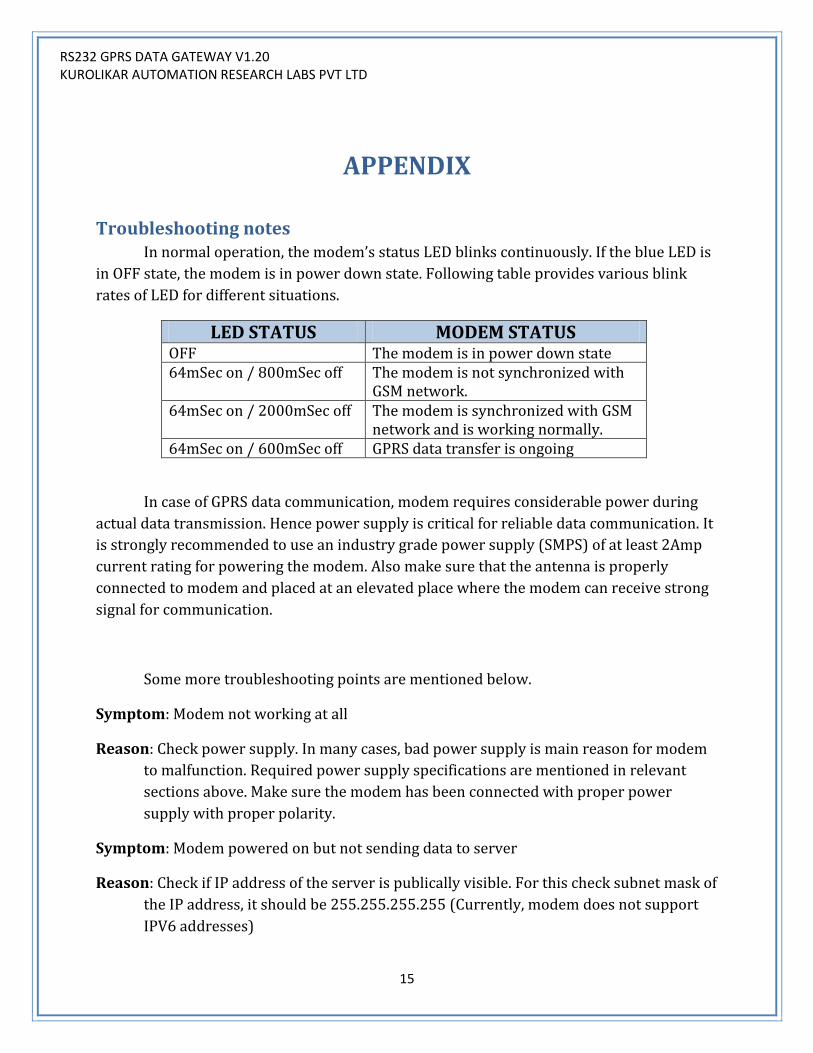
Troubleshooting notes In normal operation, the modem’s status LED blinks continuously. If the blue LED is
in OFF state, the modem is in power down state. Following table provides various blink
rates of LED for different situations.
LED STATUS MODEM STATUS OFF The modem is in power down state 64mSec on / 800mSec off The modem is not synchronized with
GSM network. 64mSec on / 2000mSec off The modem is synchronized with GSM
network and is working normally. 64mSec on / 600mSec off GPRS data transfer is ongoing
In case of GPRS data communication, modem requires considerable power during
actual data transmission. Hence power supply is critical for reliable data communication. It
is strongly recommended to use an industry grade power supply (SMPS) of at least 2Amp
current rating for powering the modem. Also make sure that the antenna is properly
connected to modem and placed at an elevated place where the modem can receive strong
signal for communication.
Some more troubleshooting points are mentioned below.
Symptom: Modem not working at all
Reason: Check power supply. In many cases, bad power supply is main reason for modem
to malfunction. Required power supply specifications are mentioned in relevant
sections above. Make sure the modem has been connected with proper power
supply with proper polarity.
Symptom: Modem powered on but not sending data to server
Reason: Check if IP address of the server is publically visible. For this check subnet mask of
the IP address, it should be 255.255.255.255 (Currently, modem does not support
IPV6 addresses)

RS232 GPRS DATA GATEWAY V1.20 KUROLIKAR AUTOMATION RESEARCH LABS PVT LTD
16
Symptom: Modem powered on but not responding to any SMS queries
Reason: Check modem without connecting any device on bus. Many times wrong bus
connections make the modem receive garbage data over bus and this result in
modem continuously resetting itself trying to recover from the situation.
Also check if SIM card has sufficient space free to receive SMS. Check if antenna
is properly connected and placed at elevated location.

RS232 GPRS DATA GATEWAY V1.20 KUROLIKAR AUTOMATION RESEARCH LABS PVT LTD
17
Warranty statement
All the products mentioned in this manual are covered under warranty for a period of
12 months against manufacturing defects, workmanship and malfunction under normal
operating conditions. The warranty is subject to the terms and conditions mentioned
below.
1. The warranty commences from the date of sale for a period of 12 months
irrespective of the actual installation date.
2. The warranty is against manufacturing defects and any subsequent malfunction
of the instrument during the normal operation. The warranty shall not be
applicable in case of accidental damage, damage due to wrong operation,
connection or conditions that are out of normal operating specifications. 3. KARL PL, at its discretion may repair or replace the product depending on the
condition of instrument, availability of spare parts and type of failure. 4. In case of warranty claim, the warranty period will not be extended and remains
same as stated earlier from the date of sale. 5. Maximum liability of KARL PL remains up to repair or replacement of the
product only. Any damages or losses raised out of use of the instrument are not
covered by this warranty. In any case, cost of the product will not be refunded. 6. In case of warranty claim, the product should be sent over to KARL PL
immediately after noticing the defect or failure. A detailed note of operating
conditions in which fault occurred will be helpful in rectifying the defect. 7. Do not try to open or repair the instrument on your own. Warranty will stand
null and void in such case. Products with tampered warranty seal will not be
considered for warranty claims and regular service charges will be applicable. 8. In all claims, the company’s decision will be final and legally binding. 9. Any and all disputes are subject to pune jurisdiction only.
Kurolikar Automation Research Labs Pvt Ltd
#226, Laxmi colony, Behind manish market,
Hadapsar, Pune – 411028.
www.AutomationResearchLabs.com
Email: [email protected]