R&S DST200 RF Diagnostic Chamber -...
12
Test & Measurement Product Brochure | 01.00 R&S®DST200 RF Diagnostic Chamber Accurate radiated testing of wireless devices 700 MHz to 6 GHz
Transcript of R&S DST200 RF Diagnostic Chamber -...
Te
st &
Mea
sure
men
t
Prod
uct B
roch
ure
| 01.
00R&S®DST200 RF Diagnostic ChamberAccurate radiated testing of wireless devices 700 MHz to 6 GHz
2
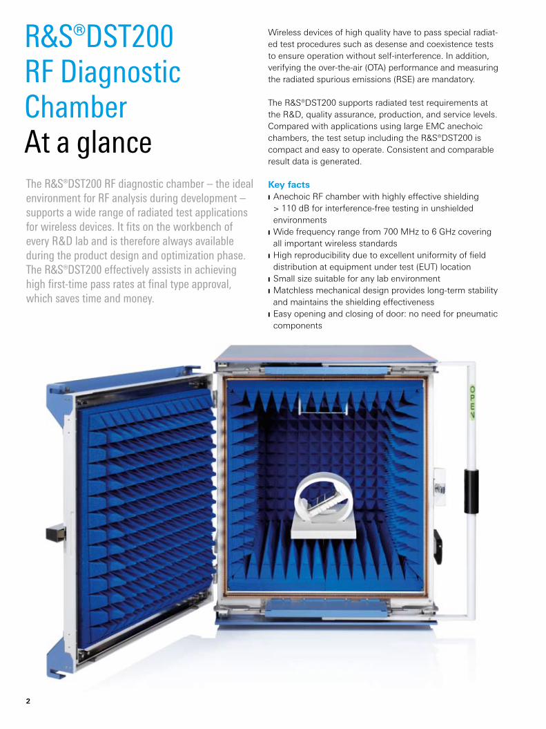
Wireless devices of high quality have to pass special radiat-ed test procedures such as desense and coexistence tests to ensure operation without self-interference. In addition, verifying the over-the-air (OTA) performance and measuring the radiated spurious emissions (RSE) are mandatory.
The R&S®DST200 supports radiated test requirements at the R & D, quality assurance, production, and service levels. Compared with applications using large EMC anechoic chambers, the test setup including the R&S®DST200 is compact and easy to operate. Consistent and comparable result data is generated.
Key factsAnechoic RF chamber with highly effective shielding ❙> 110 dB for interference-free testing in unshielded environmentsWide frequency range from 700 MHz to 6 GHz covering ❙all important wireless standardsHigh reproducibility due to excellent uniformity of field ❙distribution at equipment under test (EUT) locationSmall size suitable for any lab environment ❙Matchless mechanical design provides long-term stability ❙and maintains the shielding effectivenessEasy opening and closing of door: no need for pneumatic ❙components
The R&S®DST200 RF diagnostic chamber – the ideal environment for RF analysis during development – supports a wide range of radiated test applications for wireless devices. It fits on the workbench of every R & D lab and is therefore always available during the product design and optimization phase. The R&S®DST200 effectively assists in achieving high first-time pass rates at final type approval, which saves time and money.
R&S®DST200 RF Diagnostic ChamberAt a glance

Rohde & Schwarz R&S®DST200 RF Diagnostic Chamber 3
Shorter product development process ensures faster time-to- market ❙ Lower total cost of ownership ❙ Compact dimensions – suitable for every R & D lab ▷ page 4
Future-ready design ❙ Multiple feedthrough panels – functional test interfaces ❙ Easy integration of RF preamplifiers and switching ❙ Exchangeable test antenna ▷ page 5
Designed for excellent test results and repeatability ❙ Outstanding RF characteristics ❙ High field uniformity for variable EUT positions ❙ Manual 3D positioner ❙ Simple and effective front door mechanism ▷ page 6
Automated measurements with ready-to-use test templates ❙ Radiated measurements at a mouse click ❙ Result documentation made easy ▷ page 8
R&S®DST200 RF Diagnostic ChamberBenefits and key features
Why are radiated tests vital?
Modern smart phones include complex technologies integrated in the
smallest possible space. The RF section contains multistandard cellular
and wireless modules such as Bluetooth®, WLAN and GPS as well as
several integrated antennas. Display, camera, keyboard or touch screen
provide the interface to the user.
This mix of complex functional blocks has to be carefully harmonized to
create a fault-free design. At an early stage of the development process,
various radiated tests in free-space condition assist to achieve the
required specifications:
Receiver sensitivity tests disclose self-interference (desense) effects ❙of the design and additionally verify the coexistence of multiple radio
services
Spatial tests of the total radiated power (TRP) and the total isotropic ❙sensitivity (TIS) verify the over-the-air (OTA) antenna performance and
ensure a high quality of service at the edge of network cells
Measurements of the radiated spurious emissions (RSE) verify that ❙there is no interference to other radio services
What is desense?
The term desense refers to the desensitization of receiver performance.
It is caused by interference between components created by effects
such as oscillator harmonics, internal noise on the printed board or
antenna crosstalk.
The result is a reduced quality of service, e.g. dropped calls on specific
channels at the edge of network cells.
What is coexistence of radio services?
Coexistence means the simultaneous operation of multiple radio services
in a wireless device. These services may cause mutual degradation
of receiver performance. For example, harmonics of a GSM transmit
channel can disrupt a WLAN receive channel. As an effect, the quality of
service deteriorates; disrupted data packets have to be repeated, which
lowers the data throughput.
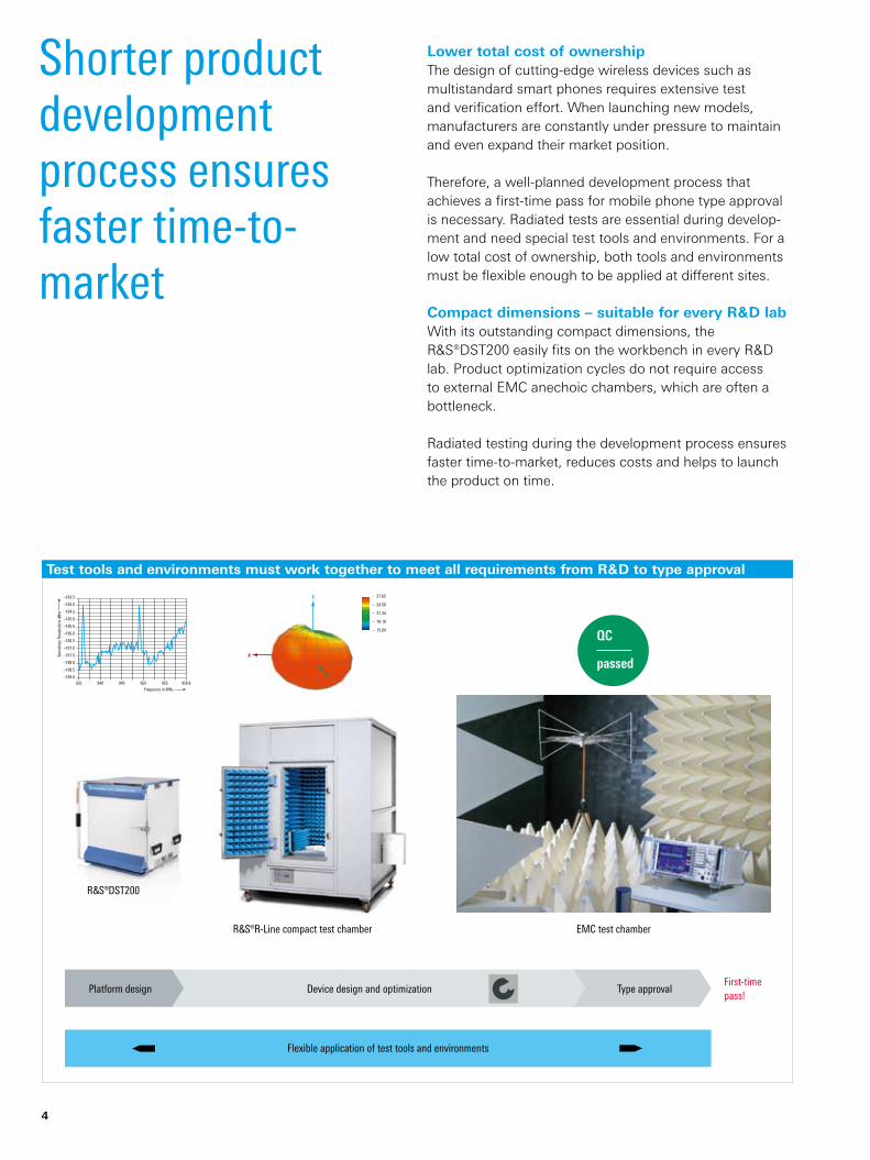
QC–––––passed
–103.5
–104.0
–104.5
–105.0
–105.5
–106.0
–106.5
–107.0
–107.5
–108.0
–108.5
–109.0935 945940 950 955 959.8
Sens
itivi
ty T
hres
hold
in d
Bm
Frequency in MHz
¸R-Line compact test chamber EMC test chamber
Device design and optimization Type approval
Flexible application of test tools and environments
First-timepass!
¸DST200
Platform design
4
Shorter product development process ensures faster time-to- market
Lower total cost of ownershipThe design of cutting-edge wireless devices such as multi standard smart phones requires extensive test and verification effort. When launching new models, manufacturers are constantly under pressure to maintain and even expand their market position.
Therefore, a well-planned development process that achieves a first-time pass for mobile phone type approval is necessary. Radiated tests are essential during develop-ment and need special test tools and environments. For a low total cost of ownership, both tools and environments must be flexible enough to be applied at different sites.
Compact dimensions – suitable for every R & D labWith its outstanding compact dimensions, the R&S®DST200 easily fits on the workbench in every R & D lab. Product optimization cycles do not require access to external EMC anechoic chambers, which are often a bottleneck.
Radiated testing during the development process ensures faster time-to-market, reduces costs and helps to launch the product on time.
Test tools and environments must work together to meet all requirements from R & D to type approval

Rohde & Schwarz R&S®DST200 RF Diagnostic Chamber 5
Future-ready design With a frequency range from 700 MHz to 6 GHz, the R&S®DST200 can measure all common wireless standards.The modular design with accessible top and bottom com-partments provides flexibility to install additional hardware for specific test demands. Due to this concept, the field characteristics of the measurement area are not affected.
Multiple feedthrough panels – functional test interfacesIn many cases, tests require access to external interfaces of the EUT. Typical test functions are charger operation, control of the test mode interface or data throughput measurements as well as activation or deactivation of components such as a display or a camera. The bottom compartment provides three locations for installing various RF feedthroughs and filtered lines:
9-pin D-Sub lowpass filter and two fiber-optic ❙feedthrough connectors (R&S®DST-B101 option)Two N feedthrough connectors (R&S®DST-B102 option) ❙USB 2.0 lowpass filter (R&S®DST-B103 option) ❙
Easy integration of RF preamplifiers and switchingAn accessible compartment at the top of the R&S®DST200 enables the integration of RF circuits between the test antenna and test instruments. For example, preamplifiers may be used to extend the dynamic range for emission measurements, or RF switching can be implemented to distribute the test signal to different test instruments.
Exchangeable test antennaThe broadband test antenna is installed as one module and can be easily replaced by other versions required for specific applications, such as for frequencies above 6 GHz.
Top compartment for integration of
RF circuits.
Bottom compartment contains RF
and signal feedthrough connectors
for conducted test operation.

6
Designed for excellent test results and repeatability
Outstanding RF characteristicsThe R&S®DST200 is a compact RF shielded anechoic chamber with an integrated broadband test antenna (700 MHz to 6 GHz ).
At the test position of the EUT, free-space conditions are achieved by the optimized layout of pyramidal RF absorbers. They minimize parasitic loading of the EUT and antenna detuning caused by conductive parts of the chamber frame.
For example, testing the performance of GPS receivers down to very low levels of –160 dBm requires perfect RF shielding of the test setup. With its outstanding shielding effectiveness of 110 dB, the R&S®DST200 blocks all interferers present, either from adjacent test setups in the lab, or from external sources such as base stations or TV transmitters.
High field uniformity for variable EUT positionsThe circularly polarized test antenna provides high uniformity of the field at the EUT location. Reproducible test results are obtained even when the position of the EUT is slightly changed.
Typically, RF chambers with near-field antenna couplers require a fixture for precise EUT positioning. With the R&S®DST200, the wireless device is simply placed on the table at the bottom of the chamber, without any need for extensive position adjustments.
Maximum variation of electric field at cylindrical EUT volume above the
EUT table (D = 200 mm, H = 30 mm).
Spatial distribution of electric field radiated by the test antenna at two
vertical planes; f = 950 MHz. The origin of the coordinate system is
located in the center of the EUT table.
Rohde & Schwarz R&S®DST200 RF Diagnostic Chamber 7
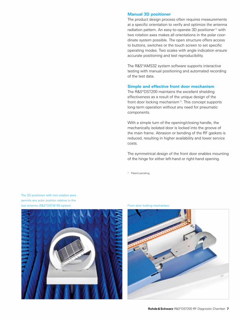
Manual 3D positionerThe product design process often requires measurements at a specific orientation to verify and optimize the antenna radiation pattern. An easy-to-operate 3D positioner 1) with two rotation axes makes all orientations in the polar coor-dinate system possible. The open structure offers access to buttons, switches or the touch screen to set specific operating modes. Two scales with angle indication ensure accurate positioning and test reproducibility.
The R&S®AMS32 system software supports interactive testing with manual positioning and automated recording of the test data.
Simple and effective front door mechanismThe R&S®DST200 maintains the excellent shielding effectiveness as a result of the unique design of the front door locking mechanism 1). This concept supports long-term operation without any need for pneumatic components.
With a simple turn of the opening/closing handle, the mechanically isolated door is locked into the groove of the main frame. Abrasion or bending of the RF gaskets is reduced, resulting in higher availability and lower service costs.
The symmetrical design of the front door enables mounting of the hinge for either left-hand or right-hand opening.
1) Patent pending.
The 3D positioner with two rotation axes
permits any polar position relative to the
test antenna (R&S®DST-B150 option). Front door locking mechanism.
8
Automated measurements with ready-to-use test templates
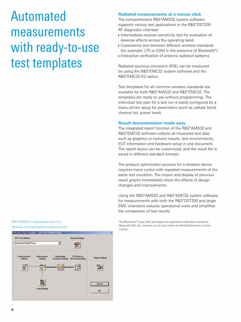
Radiated measurements at a mouse clickThe comprehensive R&S®AMS32 system software supports various test applications in the R&S®DST200 RF diagnostic chamber:
Intermediate receiver sensitivity test for evaluation of ❙desense effects across the operating bandCoexistence test between different wireless standards ❙(for example, LTE or GSM in the presence of Bluetooth®)Interactive verification of antenna radiation patterns ❙
Radiated spurious emissions (RSE) can be measured by using the R&S®EMC32 system software and the R&S®EMC32-K2 option.
Test templates for all common wireless standards are available for both R&S®AMS32 and R&S®EMC32. The templates are ready to use without programming. The individual test plan for a test run is easily configured by a menu-driven setup for parameters (such as cellular band, channel list, power level).
Result documentation made easyThe integrated report function of the R&S®AMS32 and R&S®EMC32 software collects all measured test data such as graphics or numeric results, test environments, EUT information and hardware setup in one document. The report layout can be customized, and the result file is saved in different standard formats.
The product optimization process for a wireless device requires many cycles with repeated measurements of the same test condition. The import and display of previous result graphs immediately show the effects of design changes and improvements.
Using the R&S®AMS32 and R&S®EMC32 system software for measurements with both the R&S®DST200 and larger EMC chambers reduces operational costs and simplifies the comparison of test results.
R&S®AMS32 configuration menu for
desense and coexistence measurements.
The Bluetooth® word mark and logos are registered trademarks owned by Bluetooth SIG, Inc. and any use of such marks by Rohde & Schwarz is under license.

Rohde & Schwarz R&S®DST200 RF Diagnostic Chamber 9
ApplicationRadiated performance test verifies product quality
Desense test (self-interference)Multistandard smart phones include many functional blocks, integrated in the smallest possible space to meet market requirements. The different components can interfere with each other; especially the performance of the receiver part may be degraded. This effect is called desense and originates from oscillator harmonics or internal crosstalk in the printed board layout. Emissions from the display, camera or other functional blocks can also cause interference.
The desense measurement requires an active link with a radiocommunication tester (such as the R&S®CMU200, R&S®CMW500 or R&S®CBT) to provide the required cellular or wireless service. After the link is established, either bit error rate (BER) or packet error rate (PER) measurements are performed while a potential interferer is active (for example, the display).
Coexistence testAnother important design-relevant test is to verify the correct functioning of simultaneously operating radios in the wireless device, such as multiband cellular engines, GPS receiver, Bluetooth® or Wi-Fi. The usual test method is to first set up a communications link with the presumed interferer. Next, the possibly affected service is tested by measuring the receiver degradation in the same way as for the desense test.
Test cases for coexistence testing are required by the CTIA wireless association and are specified in the “Test Plan for RF Performance Evaluation of Wi-Fi Mobile Converged Devices”.
Desense test result with self-interference
on two channels for a GSM 900 band.
Test setup for desense measurements
with the R&S®CMW500.

10
Measurement of radiated spurious emissions (RSE)The frequency spectrum is a valuable resource for service providers. The network capacity must not be degraded by spurious emissions from wireless devices. Radiated harmonics and spurious emissions have to be tested in line with the 3GPP and ETSI test specifications for cellular or any other wireless standard. Further mandatory tests are defined by the Federal Communications Commisson (FCC) and the R&TTE directive.
Both the spurious emissions in the operating band and the out-of-band emissions that may affect other services have to be below a specified limit. In-band tests require suppression of the carrier frequency to avoid overloading of the test receiver input. The R&S®OSP-F7B modular filter unit includes switchable notch filters that can be con-figured for specific operating bands. The R&S®OSP-F7B is simply inserted between the test antenna of the R&S®DST200 and the input of the test receiver.
Verification of over-the-air (OTA) performanceFor verification of the total radiated power (TRP) and total isotropic sensitivity (TIS), as specified by CTIA (and similar-ly by 3GPP), the R&S®DST200 supports evaluation of both the radiated pattern and the receiving characteristic. The results correlate with those from larger over-the-air (OTA) test chambers. The antenna design of a wireless device can be optimized in the R & D lab without continuous access to external test chambers.
Example of antenna radiation pattern
for GSM 1900 for the receiver sensitivity,
three cuts (theta = 60°, 90° and 120°).
Example of a GSM 850 RSE test with
a 3rd harmonic of the uplink carrier.
3rd harmonic at 2472 MHz
Rohde & Schwarz R&S®DST200 RF Diagnostic Chamber 11
Your local Rohde & Schwarz expert will help you determine the optimum solution for your requirements.To find your nearest Rohde & Schwarz representative, visit www.sales.rohde-schwarz.com
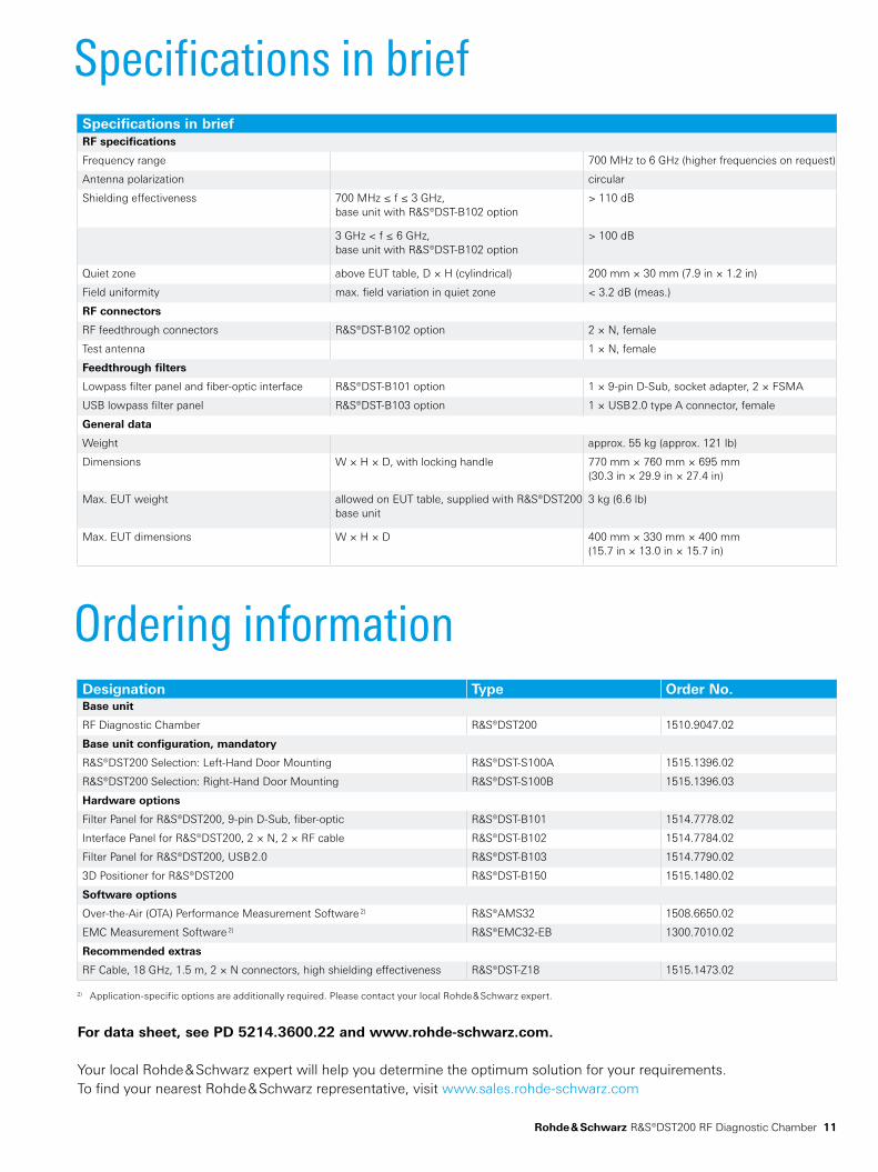
Specifications in briefSpecifications in briefRF specifications
Frequency range 700 MHz to 6 GHz (higher frequencies on request)
Antenna polarization circular
Shielding effectiveness 700 MHz ≤ f ≤ 3 GHz, base unit with R&S®DST-B102 option
> 110 dB
3 GHz < f ≤ 6 GHz, base unit with R&S®DST-B102 option
> 100 dB
Quiet zone above EUT table, D × H (cylindrical) 200 mm × 30 mm (7.9 in × 1.2 in)
Field uniformity max. field variation in quiet zone < 3.2 dB (meas.)
RF connectors
RF feedthrough connectors R&S®DST-B102 option 2 × N, female
Test antenna 1 × N, female
Feedthrough filters
Lowpass filter panel and fiber-optic interface R&S®DST-B101 option 1 × 9-pin D-Sub, socket adapter, 2 × FSMA
USB lowpass filter panel R&S®DST-B103 option 1 × USB 2.0 type A connector, female
General data
Weight approx. 55 kg (approx. 121 lb)
Dimensions W × H × D, with locking handle 770 mm × 760 mm × 695 mm(30.3 in × 29.9 in × 27.4 in)
Max. EUT weight allowed on EUT table, supplied with R&S®DST200 base unit
3 kg (6.6 lb)
Max. EUT dimensions W × H × D 400 mm × 330 mm × 400 mm(15.7 in × 13.0 in × 15.7 in)
Ordering informationDesignation Type Order No.Base unit
RF Diagnostic Chamber R&S®DST200 1510.9047.02
Base unit configuration, mandatory
R&S®DST200 Selection: Left-Hand Door Mounting R&S®DST-S100A 1515.1396.02
R&S®DST200 Selection: Right-Hand Door Mounting R&S®DST-S100B 1515.1396.03
Hardware options
Filter Panel for R&S®DST200, 9-pin D-Sub, fiber-optic R&S®DST-B101 1514.7778.02
Interface Panel for R&S®DST200, 2 × N, 2 × RF cable R&S®DST-B102 1514.7784.02
Filter Panel for R&S®DST200, USB 2.0 R&S®DST-B103 1514.7790.02
3D Positioner for R&S®DST200 R&S®DST-B150 1515.1480.02
Software options
Over-the-Air (OTA) Performance Measurement Software 2) R&S®AMS32 1508.6650.02
EMC Measurement Software 2) R&S®EMC32-EB 1300.7010.02
Recommended extras
RF Cable, 18 GHz, 1.5 m, 2 × N connectors, high shielding effectiveness R&S®DST-Z18 1515.1473.02
2) Application-specific options are additionally required. Please contact your local Rohde & Schwarz expert.
For data sheet, see PD 5214.3600.22 and www.rohde-schwarz.com.
R&S® is a registered trademark of Rohde & Schwarz GmbH & Co. KG
Trade names are trademarks of the owners | Printed in Germany (ft)
PD 5214.3600.12 | Version 01.00 | June 2010 | R&S®DST200
Data without tolerance limits is not binding | Subject to change
© 2010 Rohde & Schwarz GmbH & Co. KG | 81671 München, Germany
About Rohde & SchwarzRohde & Schwarz is an independent group of companies specializing in electronics. It is a leading supplier of solu-tions in the fields of test and measurement, broadcast-ing, radiomonitoring and radiolocation, as well as secure communications. Established more than 75 years ago, Rohde & Schwarz has a global presence and a dedicated service network in over 70 countries. Company headquar-ters are in Munich, Germany.
Environmental commitmentEnergy-efficient products ❙Continuous improvement in environmental sustainability ❙ISO 14001-certified environmental management system ❙
Certified Quality System
ISO 9001
Rohde & Schwarz GmbH & Co. KGwww.rohde-schwarz.com
Regional contactEurope, Africa, Middle East ❙+49 89 4129 137 74 [email protected] America ❙1 888 TEST RSA (1 888 837 87 72) [email protected] America ❙+1 410 910 79 88 [email protected]/Pacific ❙+65 65 13 04 88 [email protected]
Service you can rely onJ Worldwide J Local and personalizedJ Customized and flexibleJ Uncompromising qualityJ Long-term dependability