RR-696 - Design Review of Breakaway Sign Supports … · Current Criteria: o ''Standard...
31
I '·,I '-I .-.) 1 I Design Review of Breakaway Sign Supports Osed by Michigan Department of Transportation c Federal Highway Administration Michigan Division December 1988
Transcript of RR-696 - Design Review of Breakaway Sign Supports … · Current Criteria: o ''Standard...
I '·,I '-I
.-.)
1 I
Design Review of Breakaway Sign Supports Osed by Michigan Department
of Transportation
c
Federal Highway Administration Michigan Division
December 1988
Design Review of Breakaway Sign Supports Used by Michigan DOT
By
David A. Morena Safety and Traffic Operations Engineer
Federal Highway Administration Michigan Division Lansing, Michigan
December, 1988
Acknowledgements
I am grateful for the help I received from Michigan Department of Transportation (MOOT) personnel in preparation of this report and Dave Pawelec in particular, who assisted me in nearly every phase of report preparation.
This report was developed over a three-month period. During this time, the contents were continually revised to reflect new information, particularly regarding the MOOT tension fuse plate design, and MOOT's method of tightening slip base bolts. Lou Taylor of MOOT Design Division, Dave Pawelec of the Traffic and Safety Division and Sonny Jadun of the Materials and Technology Division not only assisted with collection of this information (reports, interviews) but also helped evaluate this information, thus contributing to several of the report's key conclusions and recommendations.
At least 15 individuals in the following MDOT sections assisted me with the task of identifying accident locations and matching them with accident reports: Traffic and Safety Division Reflective Devices Unit, Safety Programs Unit, Technical Services Unit, and Maintenance Division Overhead Sign Unit. In particular, the following individuals contributed substantial amounts of their own time and effort to directly assist me with the data collection: Again, Dave Pawelec spent probably 20 hours with me identifying study locations (review of maintenance files) and matching those locations with hard copy accident reports (review of sign inventory and photo log); Mary Beth McClain and ,Jack Benac helped me locate and print copies of matching accident reports; Mr. Benac further obtained vehicle weight data for the vehicles identified in this study. John Green of the University of Michigan Transportation Research Institute also assisted in identification of vehicle weights.
Finally, my secretary willingly persisted through numerous rewrites, which enabled me to incorporate MOOT comments and new information as received during the course of the review.
TABLE OF CONTENTS
Introduction
Purpose
Procedure
Scope
Findings:
Stub Height
Change in Momentum/Velocity Wood Posts Slip Base
Keeper Plate Method of Tightening Bolts Effect of Bolt Material and Lubrication
Frangible Couplings Steel Posts Proposed Criteria
Height of Sign/Upper Hinge Above Ground
Design of Upper Hinge Steel Column
Tension Fuse Plate Post-to-Panel Connection
Wood Post
Accident Review
Available Data Files Study Data Base Analysis
Conclusions
Recommendations
References
i
Page 1
1
1
2
2-14
3
4 4 5 6 6 8 8 8 9
9
ll ll ll 13 13
14-20
14 15 16
21
23
26

INTRODUCTION
In 1985, AASHTO published a revision to their ''Standard Specifications for Highway Signs, Luminaires, and Traffic Signals." Chapter 7 of this 1985 revision contains criteria for performance of breakaway supports which are more difficult to satisfy than the previous (1975) criteria.
The two main changes in the new criteria are the use of the 1800 lb. car (previous 2250 lb.) for the design vehicle, and the maximum stub height requirement of 4" (previous 6") remaining after vehicle impact.
MDOT has made a few design changes, in the area of stub height, to their breakaway sign supports, but has delayed implementing the stricter testing requirements (1800 lb. vehicle), pending dynamic testing and FHWA adoption of the revised AASHTO specifications. FHWA also has intentionally delayed adopting Chapter 7 for Federal-aid construction, pending results of a crash-testing program and public comment. FHWA's initial crash-testing program has now been completed, and the public comment period closed on March 14, 1988. FHvJA adoption of the 1985 Chapter 7 criteria is expected soon, with MDOT adoption to follow.
PURPOSE
The main purpose of this review was to assess the degree of conformance in existing MDOT sign support designs with the breakaway support criteria that are likely to be adopted by FHWA and MDOT in the near future. A secondary purpose of this review was to assess MDOT designs for conformance with the 1975 AASHTO breakaway criteria.
In addition, the study was broadened to assess the degree of conformance in the MDOT designs with other aspects of breakaway support design, as found in AASHTO and FHWA guidelines, that are not specifically addressed in the above mentioned ''Standard Specifications.''
PROCEDURE
MDOT's Traffic and Safety Division, Reflective Devices Unit, maintains a standardized set of design plans specifying design and placement of breakaway sign supports. These "standard" plans are internal to that Division--they are not submitted to FHWA for approval as are the Design Division's Standard Plans. For this review, I obtained these plans from John Kanillopoolos, Supervisor of the Reflective Devices Unit, reviewed the plans, and then discussed them with John and his staff. Through the course of the review, additional discussions were held with personnel from MDOT's Design, Construction, Maintenance, and Materials & Testing Divisions.
The MDOT designs were compared to both current and proposed national design criteria. The following standards and guides were used for this comparison:
-1-
Current Criteria:
o ''Standard Specifications for Structural Supports for Highway Signs, Luminaires, and Traffic Signals,'' AASHTO, 1975.
o ''Traffic Control Devices Handbook," FHWA, 1983.
Proposed Criteria:
o "Standard Specifications for Structural Supports for Highway Signs, Luminaires, and Traffic Signals, AASHTO, 1985.
o Proposed "AASHTO Roadside Design Guide," ballot draft, August, 1988.
Performance of various breakaway or yielding sign supports in testing has been documented in several reports. For this study, I consulted six reports from the office library regarding test results; I also reviewed two reports on design of slip base, two reports on tension fuse plates, and six reports or references on the theory, design, and operational aspects of bolting. I supplemented this material with discussions with Nick Artimovich of the FHWA Washington Office of Design, Charlie McDevitt, and Len Meczkowski of the FHWA Washington Office of Research, and John H. Botts of ,John H. Botts, Inc., a manufacturer of high-strength bolts. I also contacted FHWA staff in our Texas, Arizona, Wisconsin, and California Division offices to discuss slip base designs tested and used by those State DOTs.
To obtain information on field experience of the ~1DOT designs, I interviewed Jerry Rademacher and Roy Rohrbacher of MDOT Maintenance Division, Statewide Overhead Sign Unit. These two men have a combined 57 years of experience in this unit, which is responsible for repair of damaged large sign supports statewide. In addition, accident experience of the large sign supports on freeways was reviewed for a 3 1/2 year period, January, 1985, through June, 1988.
SCOPE
Design features which are pertinent to the performance of breakaway supports and which were the focus of this review are: force required to break or detach base support (as documented by dynamic testing); stub height remaining; height of upper hinge above ground; performance of upper hinge; and number of supports permitted for simultaneous impact. The last three features apply only to multiple sign supports.
FINDINGS
MDOT has designed eight distinct breakaway or yielding sign supports:
4'' x 6'' wood post (Standard Plan S3-30A) 6'' x 8" wood post (with 3 1/2'' holes)--(S3-30A)
H8 x 13 steel column on horizontal slip base (VIII-44, VIII-45) W8 x 18 steel column on horizontal slip base (VIII-44, VIII-45) Break-Safe frangible couplings (VIII-100) 3 lb. steel U-channel post (S3.10, VIII-31) 4 lb. steel U-channel post (S3.10) 6 lb. steel IJ-channel post (VIII-31)
-2-
- -. -" -·-.- ---. '"';
Of these eight designs, only five are widely used by t1DOT: the two woorl post designs, the two steel column designs, and the 3-lb. U-channel. The 6 lb. U-channel is now installed only behind guardrail; the 4 lb. U-channel is not called for anymore; and the Break-Safe, when allowerl as a bidding alternative, has continually lost out to the steel column designs.
STUB HEIGHT:
Current national criteria for stub height remaining after impact is 6" maximum. Proposed criteria is 4'' maximum.
Wood Posts: These designs satisfy current criteria with stub heights which are variable, but generally below 6". The 4" x 6" post typically breaks off at ground level (O" stub). Stub height for the 6" x 8" wood post is debatable: the centerline of the lower hole is set at 6" above ground level, but the post typically breaks by shattering in the area between the hole and the ground. The remaining stub is seldom 6'' high, and often is not full cross-section. Neither post design requires an above ground foundation, so slope of terrain does not affect stub height.
To satisfy the proposed criteria (4" max.), in my op1n1on, the 6" x 8" wood post design should be modified by lowering the centerline of the lower hole to 4" above ground. That would result in the bottom of that hole being 2 l/4'' above ground, and the bituminous sealing around the post would have to be designed low enough to avoid trapping water in the hole. MDOT may choose to retain the current design, however, and test for stub height: it is possible that the current design may satisfy the 4" stub criteria, as a result of reduced cross-section and shattering of the post.
Slip Bases: The two MOOT slip base designs have been modified to produce a stub height of 3" when installed on level ground. However, the 3" is dimensioned at the center of the foundation; foundations which are located on a 1-on-6 sideslope, front or back, can result in stubs of approximately 6". On a l-on-4 slope, both the steel stub and the concrete foundation would project above 6''. The design should be modified for use on slopes.
Frangible Coupling: This design leaves a stub height of l l/2'' when installed on level ground, but this stub height becomes nearly 5" on a l-on-6 slope and nearly 7'' on a 1-on-4 slope, due to the design of the concrete foundation. In these cases, the corner of the foundation itself becomes the stub. The foundation design should be modified regarding installation on slopes.
Steel Posts: The three steel posts bend on impact; therefore, stub projection is not a factor, but post embedment is. Embedment of 3'6'' is the maximum recommended for yielding posts, unless the posts are anchored with concrete collars, steel sleeves, etc. MDOT's design requires embedment of 3'6'' l" for each post type, which is acceptable as meeting the spirit of the guidelines. It should be noted that the MDOT 6 lb./ft. design is anchored with a concrete collar.
-3-
CHANGE IN MOMENTUM/VELOCITY:
Current national criteria for dynamic performance is that the maximum change in momentum for a 2250 lb. vehicle impacting the support at 20-to-60 mph will not exceed 1100 lb.-sec., and desirably will not exceed 750 lb.-sec.
Wood Posts: In pendulum testing (Reference l) done in 1977 by Southwest Research Institute specifically for MOOT, documented changes in momentum for the MOOT wood post designs were as follows:
4" x 6'' wood post 6" x 8" wood post
142-168 lb.-sec. (3 tests) 278 lb.-sec. (l test)
Based on these tests, our office accepted the MOOT designs as being well within the national criteria. However, those reported change of momentum figures very likely understate the true change of momentum which a 2250 lb. vehicle would experience when striking either type support. The national testing guidelines were undergoing a refinement in 1977-1980 whereby the recommended configuration of the pendulum nose was modified to better represent the crushabi l i ty of a small car ( 2). In the SWRI testing, the 142-278 lb.-sec. values were obtained in tests using the older (original) nose configuration. SWRI did perform two tests for MOOT using the new (modified) nose configuration and the resulting change of momentum values were much higher:
4'' x 6'' wood post (with l l/2'' drilled holes)--406 lb.-sec. 6" x 8" wood post (with 2 l/4" drilled holes, alongside 5/8" holes)--
546 lb.-sec.
Furthermore, in the only reported crash test (3) that I can locate, a 4" x 6" post with no holes produced a momentum change of 525 lb.-sec. in a 2250 lb. car. (This test may overstate the momentum change for the MOOT design because the post was not anchored in concrete as required by MOOT.) Therefore, although the MOOT wood post designs were tested and accepted according to the appropriate national criteria at that time, the change of momentum values originally reported are probably not correct.
Of course, even using the higher values for change in momentum, the wood posts remain well within the current breakaway criteria for single post installations. The danger lies in accumulating these values to determine number of posts permitted within an 8-foot path, which under the 1975 AASHTO Specification are taken to act together. The 1985 revision to this specification has been modified in 1988 to reduce this critical path width to seven feet.
Currently, MOOT permits three posts of either design to be used in a 7-foot path. Using what I consider to be realistic change in momentum values of 400 lb.-sec. and 550 lb.-sec., respectively, the following values are approximate estimates of cumulative momentum changes for multiple-post impacts:
1200 lb.-sec., for three 4" x 6" posts, and 1650 lb.-sec., for three 6" x 8" posts.
-4-
These values are above the maximum, and far above desirable limits for change in momentum.
Slip Base: Slip base performance is dependent upon two main design features: post size and friction clamping force. Clamping force is the amount of pressure developed on a slip base due to tightening of the four slip base bolts. To achieve a particular clamping force, national guidelines are suggested as to bolt diameter and amount of torque to be applied in tightening the bolts. Although most slip base designs across the nation are likewise specified in terms of bolt diameter and torque, it is good to remember that these are merely surrogates to obtain a desired clamping force. As will be discussed in later sections of this report, the assumed relationship between torque and clamping force can easily become distorted, due to a variety of factors.
Over a large range of values, most slip base designs are well within the current (and proposed) change-of-momentum requirements. The object in slip base designing, then, is to go beyond the crash test requirements and to optimize the design features to provide the weakest design possible to support a given sign.
Current national recommendations for design of slip bases result largely from calculations originally reported in 1968 in Highway Research Record 222 (4) and later refined in 1974 by Mr. Eugene Buth of the Texas Transportation Research Institute (5). Mr. Buth recommended lower torque values than shown in HRR 222 because he determined that the coefficient of friction in fasteners was about half that assumed in the original calculations. In effect, Buth calculated that because of the reduced loss to friction, the desired clamping force could be achieved with smaller torque on the bolts. FHWA (6) and AASHTO (7) continue to recommend the design values proposed by Buth, \~hich apparently were based on the 1800 lb. vehicle.
The following table compares the MOOT slip base designs to the 1968 and current recommended designs:
Post Size Clamping Force Bolt Diameter Torque (lb./ft.) (lb. ) ( i n. ) (ft.-lb.)
MOOT Design 13 2960 lb. 3/4 38 MOOT Design 18 2960 lb. 3/4 38 HRR 222 9-20 1740-2660 lb. 5/8 38-57 Buth/FH\JA/ AASHTO 9-20 1740-2660 lb. 5/8 19-29
It appears that the MOOT designs might have been based on the older recommendations, and that the reductions in torque suggested by Buth have not been incorporated. About ten years ago, MOOT changed from 5/8'' bolts to 3/4'' bolts to counteract wind vibration. Because the design torque was held at 38 ft.-lb., this move to a larger bolt had the unlikely effect of reducing the bolt tension (clamping force), thereby bringing the base design closer to the national guidelines.
Although MOOT's design clamping force slightly exceeds the recommended values, the current MOOT designs are still fully acceptable. In crash testing performed for FHWA in the late 1970's, a slip base support stiffer
-5-
, .. ,_

than the MDOT designs was tested and performed very well (2). The tested design incorporated a post size of 20 1 b./ft. with 3/4" bo ltstorqued to 63 ft.-lb. When this design was struck by a 2250 lb. car at 20 and 60 mph, momentum changes of 319 and 569 lb.-sec. resulted. These are within desirable limits. By comparison, the current MDOT designs would be expected to produce momentum changes even lower than that tested design, except that MDOT's keeper plate offers added resistance of unknown amount.
Keeper Plate: MDOT requires a keeper plate of 20-gauge steel for use with each slip base design. This plate was added to the design about 15 years ago, to counteract a tendency of the supports to "walk off'' their bases due to prolonged wind vibration. The keeper plate solved the "walking" problem, but the vibration continued and resulted in a new failure mode: the supports would rock the 5/8" D. base bolts, eventually snapping them on the shank at the root of the thread. To counteract this failure mode, MDOT modified the design in 1978 to require the 3/4" bolts currently shown on the standard plan. These 1 arger bolts have proven effective against wind vibration.
The proposed AASHTO Roadside Design Guide acknowledges that keeper plates of 20-28 gauge steel are in use, but makes no recommendations 11ithin that range (20-gauge is more than twice as thick as 28-gauge). FHWA recommends use of 28-gauge steel (1/67 in. thick before galvanizing), on the philosophy that this gauge is thick enough to prevent ''walking" but thin enough to not inhibit the breakaway action of the slip base. The thickest keeper plate that has been crash-tested to date is a 20-gauge steel plate (1/28 in. thick) used in successful Arizona DOT testing on 1800 lb. cars (6). The tested Arizona design had smaller steel supports (S4 x 7.7) than Michigan, and the slip base bolts in that test were torqued to only 17 ft.-lb. Because of those variations, the Arizona testing cannot be used to verify the MDOT practice of using 20-gauge keeper plates with heavier posts, and slip bases torqued to 38 ft.-lb. per bolt; yet the Arizona results were so good I expect the MDOT design would pass easily if tested. As a matter of good design, MDOT should nevertheless consider whether a thinner-gauge steel could satisfy their design goals for the keeper plate. If corrosion is a concern, a heavier-than-normal galvanized coating would be a safer alternative to use of lower gauge steel.
MDOT does not permit multiple slip base supports within a 7-foot path. Nevertheless, it is quite likely that two posts of either design hit simultaneously would produce acceptable momentum changes according to current criteria.
Method of Tightening Bolts: The galvanization of the bolts (and nuts) in MOOT's slip base design has made field construction to the design clamping force very difficult. Two different methods of bolt tightening have been used, and each has been unsuccessful, as discussed in the following paragraphs.
Prior to 1985 (approx.), MDOT's contractors and maintenance crews tightened the slip base bolts with a torque wrench. As previously discussed, when the design torque (38 ft.-lb.) registers on the torque wrench, the desired clamping force on the slip base is supposed to be simultaneously reached. MDOT maintenance crews found that due to the variation from one galvanized bolt to another, the resulting clamping force on the slip base varied
-6-
enormously from one slip base to another when bolt tightening ceased at 38 ft.-lb. It should be noted that MDOT did follow the standard practice of tightening each bolt past the design torque, backing it off, and retightening it. Although this practice would remove burrs or other aberrations in the steel, it apparently did not eliminate the highly variable friction due to galvanization. Consequently, slip bases tightened by this· method were not reliably tight. This probably contributed to some of the early wind load failures, but would not be considered a threat to the safety performance of the slip base because, if anything, the slip bases were under-tightened.
Several years ago, MDOT abandoned this torque wrench method of tightening galvanized bolts in favor of the turn-of-the-nut method, in which a bolt is brought to a "snug fit" condition, then rotated a specific amount beyond that. No written instructions were issued to either Maintenance or Construction Division personnel, but somehow both adopted a practice of tightening these bolts to snug fit plus l/4 nut rotation.
The turn-of-the-nut method is recognized as a legitimate fastening method for bolts in friction applications by the American Institute of Steel Construction (8). Furthermore, MDOT personnel and a well-respected industry souri:e\Mr. Botts) consider the turn-of-the-nut method to be more reliable for obtaining a desired clamping force than the torque wrench method, when using galvanized fasteners as in the MOOT design.
However, this general preference toward turn-of-the-nut method is actually geared toward strong bolt connections, such as used in bridge construction or sign trusses. For weak connections, such as slip base bolts, the turn of the nut method would seem difficult, if not impossible, to apply. According to testing performed by MOOT's Materials & Testing Division (9) in 1985, the "snug fit" condition in itself produces 7000-to-15,000 pounds of bolt tension in a 3/4" D. bolt, depending on the man and tool used to reach snug fit. By comparison, the AASHTO recommended bolt tension for MOOT's steel columns is 2660 lb. maximum per bolt. The positive l/4 nut rotation currently being applied to MDOT designs would increase the final bolt tension to the neighborhood of 25,000-30,000 lb./bolt, equivalent to 320-380 ft.-lb. of torque.
It is apparent, then, that the nut would have to be loosened, not tightened, from the snug fit condition to reach the 38 ft.-lb. specified in the MOOT design. Backward rotation from snug fit does not seem to be within the scope of the turn-of-the-nut method. Even if backward rotation (nut loosening) could be calibrated, the final torque/bolt tension would still be highly variable due to the apparent variability in snug fit from one connection to another.
Torque wrenching and turn-of-the-nut are the two most popular and inexpensive methods of tightening bolts to a specific bolt tension. It seems apparent from the above discussion that neither of these methods can be used to reliably produce the relatively weak tension desired in slip base bolts, when the bolts are galvanized. A design change to stainless steel bolts is an attractive alternative here, as that would permit a return to fairly reliable torquing by the torque wrench method. Stainless steel bolts would be compatible with the other components of the slip base
-7-
(galvanized steel); that is, no galvanic corrosion is expected between adjacent materials. Another alternative which MOOT might want to investigate is the use of torque-control washers, which flatten under a specified force.
Effect of Bolt Material, Lubrication on Torque/Clamping Force Relationship: The AASHTO and FHWA guidelines which link a recommended torque to a desired clamping force are usually presented without regard to bolt material or lubrication, but they were in fact developed based on the properties of non-lubricated, galvanized nuts and bolts. This is important to know, because the torque-clamping force relationship varies with bolt material, surface, texture, and lubricant used in the connection (10). For instance, a galvanized connection tightened with no lubrication will develop 38 ft.-lbs. of torque during tigi1tening (due to internal friction between threads) much sooner than that same connection if lubrication is applied. That is, with the same applied torque, the lubricated connection will tighten further and produce more clamping force on the slip base than will the non-lubricated connection. The same variability is to be expected between different materials, such as galvanized vs. stainless steel bolts.
Therefore, if MOOT does switch to stainless steel bolts, the torques recommended in the national guidelines would not apply. The desired clamping force shown in the guidelines would apply, but MOOT would have to establish through testing the amount of torque required to provide that design clamping force in stainless steel bolts. This testing could be performed easily and quickly at the MOOT Materials and Testing Division research laboratory.
Frangible Coupling: The Break-Safe frangible coupling is a proprietary design manufactured by Transpo Industries. Transpo has not crash-tested this design. The Break-Safe coupling is considered acceptable, however, by favorable comparison to a similar coupling design in use by New Jersey. The New Jersey design has been tested (11) with an 1800 lb. car at speeds of 20.8 and 59.9 mph. Changes in moment~respectively, for those tests were 416 and 477 lb.-sec. Velocity changes, respectively, were 7.8 and 9.9 feet per second. The Break-Safe design is similar in principle and uses the same grade of steel as the tested New Jersey design, except the circular fracture area in the Break-Safe is slightly smaller than the NJ design (.550 in. 00 vs •• 585 in.).
Steel Posts: MOOT's steel post U-channel designs are required by MOOT's Standard Specifications for Construction to be high carbon content billet or rail steel. In crash tests (3) conducted for FHWA, high carbon steel posts produced momentum changes in-2250 lb. cars as follows:
3 lb. steel post - 255 lb.-sec. (l test) 4 lb. steel post - no test located 6 lb. steel post - 430-996 lb.-sec. (5 tests)
The tested 6 lb./ft. steel posts were the same cross-section as MOOT's: that is, two 3 lb./ft. IJ-channel posts back-to-back. The actual momentum changes for the five tests were 430, 669, 701, 810, and 996 lb.-sec. Although all five tests produced momentum changes below the maximum, only three were below the desirable. MOOT's design, which requires a concrete collar, differs from the tested posts which were anchored by compacted soil. The effect of an anchor on 6 lb. steel posts has not been demonstrated and may just as well increase an impacting vehicle's change of momentum as decrease it.
-8-
From the above results, it is obvious that the 6 lb./ft. posts should be avoided in favor of other small post alternatives. MDOT now follows this philosophy on new installations, where the 6 lb. posts are used only behind guardrail. Furthermore, MOOT no longer uses the 4 lb. post design, because it is indistinguishable in the field from the lighter 3 lb. post.
Consequently the 3 lb. post is the only steel U-channel post exposed to traffic in new installations. It may be the safest of all MOOT designs, based on the change of momentum testing. Multiple post installations are permitted by MOOT for the 3 lb. post, with two posts permitted in a 7-foot path. This produces a combined momentum change of 510 lb.-sec. which is acceptable.
Proposed Criteria: Proposed national criteria limiting the resisting force of breakaway supports contain two substantial changes from current criteria: The design vehicle is an 1800 lb. car, and the violence of the impact is measured in velocity change (feet per second) as opposed to momentum change. These 1985 AASHTO Specifications require the velocity change for an 1800 lb. car to not exceed 15 feet per second (fps.), and desirably to not exceed 10 fps.
As the engineering community moves to adopt this new standard, testing representative of the new design vehicle will be required. Some of this testing has already been conducted (6). MDOT designs which have been proven through this new testing are: --
a) 1~8 x 13 slip base J.. b) W8 x 18 slip base
c) 3 lb. steel post
d) Break-safe frangible coupling
By comparison to successful tests (ll v ~ 9.9 and 8.8 fps. for 20 mph and 60 mph) on a much stronger comparable design (5,000 lb. clamping force, l' D. bolts, 45 lb./ft. posts) ffi.
This post was tested in strong soil only (llV ~ 6.0 and 3.1 fps. for 20 mph and 60 mph), but the general rule for yielding supports is that they offer even less resistance in weak soil because they fail by pulling out rather than fracture.
By comparison to New Jersey Design (AV~ 7.8 and 9.9 fps. for 20 mph and 60 mph).
The wood posts have not yet been tested according to the new criteria.
HEIGHT OF SIGN/UPPER HINGE ABOVE GROUND:
This design feature is intended to keep the sign face or upper post from becoming a hazard during an otherwise successful impact with a breakaway post. The 1975 AASHTO Specifications suggest that some minimum height from ground line to bottom of sign face should be established, but do not offer a value, nor has AASHTO published a value in the 1985 update of those
-9-
specifications. The Federal Highway Administration, in 1976, suggested a minimum 5 1/2' clearance, but the notice containing that recommendation has since been cancelled (12). Current guidance on the subject is available from two sources, howev~
The 1983 Traffic Control Device Handbook suggests the following::
a) Based on dynamic testing, single supports which fracture, such as wood posts, should have a minimum clearance of 6' from ground to sign bottom, with a more desirable value of 7'. This is to prevent the post remainder with sign attached from penetrating the windshield.
b) Signs on multiple supports should have 7' minimum clearance to allow vehicles to pass under the sign when impacting only one 1 eg.
Guidelines proposed for inclusion in the upcoming AASHTO Roadside Design Guide:
a) Retain the 7' m1n1mum clearance for large signs on multiple supports, and extend the concept to include 7' clearance also to the upper hinge point on the sign supports.
b) Recommend a 7' minimum clearance for single post yielding supports, such as the steel U-channel posts.
The 6' and 7' clearances recommended for signs on single posts warrant additional discussion here. The recommendation apparently stems from a series of crash tests (3) done for FHWA in the late 1970's. Those tests showed that windshield penetration was a potential problem only on the 60 mph impacts, not the 20 mph impacts. Also, the researchers concluded that while a 7' sign mounting height might be preferable for small car impacts, the 6' height might be better for large car impacts.
The above guidance, taken together, provides a comprehensive set of values for designing minimum sign/hinge height of breakaway signs. MOOT's designs compare as follows:
Wood Posts: On multiple support installations, the upper hinge is required to be a minimum 6' above ground. This should be modified to require 7' m1n1mum. On single post installations, the design is subject to interpretation but appears to require minimum clearance of 6'6" to bottom of sign panel at the post. MOOT should clarify this dimension, and should consider revising it to 7' minimum.
Slip Bases, Frangible Coupling: None of these designs specify a minimum dimension from the upper hinge to the ground. These designs should be modified to show 7' minimum.
Steel U-Channel Posts: These designs do not show an interface with sign panel, so no minimum dimension from ground to sign panel is shown. These designs should be modified to show 7' minimum clearance.
-10-
All Multi-Post Designs: None of the individual designs provide a positive control for clearance between the sign panel and the ground. Multi-post designs should be modified to require a minimum 7' clearance from the sign panel to the ground at all points.
The only control provided by MDOT is a note on the Traffic and Safety Division's "Standard Plan Index," which allows signs offset 30' or more from edge of pavement to have a minimum bottom height of 5 feet; and signs erected on a backslope, at any offset from edge of pavement, to have minimum bottom height of 4 feet.
This note is intended as a compromise with other sign location parameters in areas where a sign is either near or outside the clear zone, or up on a slope, therefore, less likely to be hit. Such parameters as maximum viewing height as measured from the roadway, and desired lateral offset from the roadway cannot always be satisfied simultaneously with a 7' bottom height parameter. This brings into question which parameter should govern, and how important is a safety feature as chances of collision diminish.
To meet existing and proposed national criteria, each individual multi-post design (wood post, slip base, and frangible coupling) should be modified to require a minimum 7' clearance from the sign panel to the ground at all points in a typical installation. The note on the Standard Plan Index should be reconsidered and possibly dropped altogether. If retained, it will require modification: neither a minimum 30' nor a backslope assures that a sign is outside the clear zone, or that a car cannot reach it. In some cases, it may be preferable to compromise on the other parameters and hold to a minimum 7' bottom height.
DESIGN OF UPPER HINGE:
Steel Column: On multi-post steel column breakaway designs (slip base, frangible coupling), MDOT uses a tension fuse plate as the upper hinge mechanism. Actually, the MDOT design requires two fuse plates, one across each flange of the post. The post is cut all the way through. This design provides a hinge feature for front and rear impacts, along the vertical plane parallel to the roadway.
There are two design goals for the fuse plate. First, the plate(s) must be strong enough to withstand the stresses induced in the post by the design wind load. Second, it must be weak enough to shear upon vehicle impact.
Strength: The fuse plate was first used in Michigan following a 1967 report (13) from MDDT's then Testing and Research Division (now Materials and Technology Division). The design recommended in that 1967 report was modified in 1969 by MDOT to incorporate AASHTO modifications in wind load assumptions that eventually were printed in the 1975 AASHTO Specifications. This modified fuse plate, still in use today, is designed to withstand a wind load of 20 psf. as produced by a 70 mph wind. The fuse plate has three holes across its mid-section to create a plane of weakness. The cross-sectional area at the plate's plane of weakness is .47 in.2 for the W8 x 18 support, and .34 in.2 for the W8 x 13 support. MOOT maintenance personnel report very few wind failures of this fuse plate design in nearly 20 years of field experience. Therefore, the current design has the needed strength.
-11-
Weakness: The current MDOT fuse plate design has not been crash-tested, but has apparently worked well in the field. Most of the accident-damaged sign supports replaced by the MDOT Overhead Sign Unit have been broken off at the front fuse plate, as the design intends. Some supports have broken at the back fuse plate as well, which is not intended by the design, but is not known to have resulted in any occupant injury. Vehicle side impacts tend not to break either fuse plate, but to rip the support away from the sign panel as discussed later in this report.
Although MOOT's fuse plate design is working well, it is worth mentioning that there is room to weaken the design, if needed in the future. A fuse plate design developed by the Texas Transportation Institute (TTI) and tested in 1982-1984 research (14) is 20% smaller in cross-section than the MDOT design. The Texas Department of State Highways has been using this weaker fuse plate since 1984 and reports no problems with wind knockdowns, even in the high-wind Corpus Christi area. Since Texas design winds equal or exceed Michigan design winds (AASHTO Specs.), this fuse plate would seem to be stron~ enough for use in Michigan. As for expected impact performance, even the weaker TTI design failed to break in a 20 mph impact with an 1800 lb. car on a W8 x 18 test installation. The researchers reported that the fuse plate almost broke in that test, and theorize that it would break at higher speeds. The idea that a particular fuse plate might fail in a high-speed impact, but not in a low-speed impact, is corroborated in the proposed AASHTO Roadside Design Guide and in reference 6.
Another aspect of fuse plate design is the grade of steel permitted in its fabrication. The MDOT design permits the fuse plate to be fabricated from various grades of steel, at the contractor's option: ASTM A36, A441, A572 Grade 50 or A 242 Type 2. Nearly this same choice of steel was permitted in the 1984 TTI design. In a technical comment on that TTl design, Mr. Charles McDevitt has pointed out that these steels are not true alternates for the task at hand (15). While it is true that these steels all have similar ultimate tensile strength, in the 70 ksi. area, the fuse plate does not function as a tension member. In its location on the flange of the steel post, fuse plate failure will be a function of plastic moment capacity, which in turn is a function of the yield stress of the steel. The yield stress of A36 is 36,000 psi., while that of the other grades of steel is 50,000 psi. Therefore, plates made of the A36 steel will yield and permit rotation sooner than plates made of the other steel alternates. Mr. McDevitt's suggestion that the fuse plate should be limited to A36 steel applies to the MOOT designs as well as to the TTl design. This is viewed as a desirable change in specification, but only a minor change in practice: A36 steel, being the cheapest grade and ready available, has hopefully been supplied all along.
It is important to note that an upper breakaway hinge is not required in order for a breakaway post to function correctly. Wisconsin DOT has recently crash-tested a breakaway multi-post design with no upper hinge (16), and that design satisfied proposed AASHTO criteria. When no hinge is provided, or when the hinge does not activate (as in the TTl test), the post may still tear away from the sign panel and rotate upward as intended, if the post-to-panel connections are sufficiently weak. In that action the impact of the vehicle is opposed throughout post rotation by the total weight of the post, rather than just the weight of the lower post. Various
-12-
,-.:·
references have suggested that 600 1 b. (7) or 800 lb. (6) should be the maximum total weight of post displacedduring impact-.-Since MOOT's heaviest post design weighs only 18 lb./ft., rotation of total post would not be considered unsafe.
Nevertheless, a working upper hinge is desirable from two standpoints:
l. MOOT feels that this feature will prevent damage to the sign face in the event of collision, and
2. This feature should further minimize the post resistance to an impacting vehicle.
In furtherance of the above two goals, I believe MOOT should review their fuse plate design to see if the cross-section could be further weakened. Also, the location of the fuse plate (upper hinge) on the posts could be referenced to the ground rather than to the bottom of the sign, as currently designed. This would limit the resisting force presented by the post, for those impacts in which the fuse plate activates. This same design philosophy would apply to the wood posts also.
Post-to-Panel Connection: The final check on the MOOT upper connection, assuming the tension fuse plate may fail to bend, is to review the connection between the steel post and the sign panel. These details are contained in the Traffic and Safety Division's Standard Plans S9.10A and VIII-142, and the 1984 Standard Specifications for Construction, Section 8.26.02e. In new construction, MOOT specifies only one sign panel material, extruded aluminum, to be used with these steel column supports.
The MOOT post-to-panel connection for extruded aluminum sign panels is nearly identical to Wisconsin's: Both WisOOT and MOOT use post clips made from aluminum alloy 356-T6. MOOT uses 3/8" stainless steel bolts, as compared to 3/8" aluminum bolts for WisDOT. Both designs use two post clips on the bottom and top of the sign panel, and alternate interior clips at approximately 12" spacing. The WisDot design, in testing, failed by pulling of the bolt head through the aluminum channel. I expect that the MOOT design would fail in a similar fashion, and with similar resistance. Conclusion: By virtue of a weak post-to-panel connection, the MOOT steel column design does not require a working fuse plate to satisfy current or proposed breakaway requirements.
Wood Posts: Both MOOT wood post designs include a saw cut on the post, 6'' below the bottom of the sign panel, which is intended to act as the upper hinge. The depth of the saw cut is l" for the 4'' x 6'' post, and l l/2'' for the 6" x 8'' post.
This hinge design has not been tested under controlled conditions, but has performed well in field experience. The 1" and 1 1/2" saw cuts rarely cause the post to fai 1 under wind loading. Yet 90-95% of the wood posts which are replaced by the statewide Overhead Sign Unit due to vehicle impact show evidence of an upper break at the saw cut. It should be noted here that this state1~ide unit has more exposure to the larger post (6" x 8") installations; usually, damaged 4" x 6" posts can be repaired by MOOT district crews, who were not interviewed for this report. An earlier MOOT design, which specified a saw cut as deep as 3 1/2'', was constructed for a period of time, but was proven to be too susceptible to wind damage.
-13-
Apparently, these saw cuts are made in the field with chain saws; depth of saw cut is therefore dependent on the skill of the chain saw operator and the vigilance of the MDOT inspector. If a saw cut were made too shallow, the upper breakaway feature would then revert to the post-to-panel connection. This connection differs for different sign panel material. Plywood sign panels are attached to the wood posts by direct bolting 3/8'' galvanized steel bolts through the post. MOOT has had some experience with this connection failing under impact in which the bolt head pulls through the plywood. However, this connection does not fail as reliably as the steel column post-to-panel connection, and some instances have occurred where the plywood sign panel itself has broken apart.
For connection to extruded aluminum sign panels, the wood posts are first fitted with an aluminum angle that runs vertically along the post for the height of the sign. The aluminum sign panel is then connected to the angle: One 3/8" stainless steel bolt at top and bottom (direct bolting) and bolts or post clips at intermediate panels. Again, according to MDOT experience, this connection fails fairly easily by having the bolt head break off, or by the bolt head pulling through the aluminum channel.
ACCIDENT REVIEW
Available Data Files: No existing file within MOOT contains all the information necessary for a review of the accident consequences to occupants of vehicles that impact the breakaway or yielding sign supports. Separate files exist as follows:
1. The MOOT Maintenance Division, Overhead Sign Unit maintains a comprehensive file on repairs that it performs statewide on the larger sign
supports (steel column on slip base, 6" x 8" wood posts, some 4" 6" wood posts). For each repair, this file describes the sign installation; number and type of posts installed; and location and number of posts which were repaired. The file is also conveniently segregated into wind-damaged vs. accident-damaged subsections. The sign repair crew classifies a repair as wind, accident, or otherwise after review of the site and the failed sign installation.
2. The MOOT Maintenance Division, Resource Control Unit receives Memorandum Job Reports from the Overhead Sign Unit for each accident-damaged sign repair and attempts to match the repaired sign installation with a police accident report, through the assistance of the State Police. (This unit is responsible for the matching activity on all MOOT property damaged by the public.) Memorandum Job Reports which cannot be matched up are thrown away. Repairs which can be matched are forwarded, with the matching accident report, to the Financial Operations Division for recovery of money from the responsible party.
There is no file maintained in the Resource Control Unit, but it is important to note that for a brief time in this unit each sign damage sheet and the accident history are matched:
a) either the matching accident report is located and attached, or b) the accident report is not located, resulting in an assumption
that the accident was a "drive-away."
-14-
It is recommended that this unit take the additional step of feeding this accident information back to the Overhead Sign Unit (20-50 repairs per year). If that were done, the Overhead Sign Unit then would have a complete file which could be accessed at any time to monitor the accident history of the large breakaway supports.
3. The Financial Operations Division, Accounts Receivable Unit, receives the matched repair/accident report sheets from the Resource Control Unit, and issues a letter to the party responsible for the accident, requesting reimbursement for damages to Department property. These letters are filed by the month in which the letter is issued.
4. The MOOT Traffic and Safety Division can generate a computer printout of accidents categorized as "Fixed Object--Highway Sign," which can be further targeted to the freeway system where the larger sign posts are mostly used. This listing is limited by the State Police coding system to identifying only those accidents in which a sign (or support) was the first object struck. Hard copy reports can then be obtained within that Division for those accidents.
Study Data Base: For this report, with the assistance of MOOT Traffic and Safety Division personnel, I obtained the accident printout discussed in Number 4 above, and compared those accident locations to 118 repair locations found in file Number l above. Hard copy accident reports were then reviewed for accident locations that appeared to match repair l ocations. A total of 51 matches were obtained over a 3 l/2 year repair period (January, 1985, through June, 1988). Repair locations for which no accident report could be found numbered 67.
During the course of the accident-matching task, an additional 60-70 freeway sign accident reports were reviewed at random and considered for addition to the data base. MOOT's sign inventory and photo log were consulted as needed to determine the type of sign support involved in each of these accidents. The majority of these were screened out as small signs on U-channel supports, or the available information was not sufficient to positively identify the type of support. However, 28 of these accidents were identified as involving a breakaway support and were added to the data base. All but one of these 28 accidents involved signs on 4'' x 6'' wood posts, most of them at freeway exit gores. Presumably, these signs did not show up in the Overhead Sign Unit's repair file because they were repaired by District forces.
Treatment of the 67 unmatched repair locations deserves some discussion here. On the one hand, since the majority of the 51 reported accidents were property damage only (PDO), it is reasonable to assume that many more accidents, perhaps all 67, went unreported because the driver, unhurt, simply drove away. On the other hand, the accident matching task is not fool-proof. A mistake in information on the police accident report could cause an accident to be coded onto the wrong part of the highway system. A mistake by myself in identifying sign location could cause me to search the wrong part of the highway system. Either of these mistakes would result in an assumption of PDO when, in reality, there might have been more serious consequences to the accident. Finally, an accident in which a vehicle hit another object (e.g., another vehicle) first, and then hit a sign would not
-15-
be coded as a sign accident, and would not show up on the one-line accident listing which I used for matching. The consequences of this scenario are not very serious: even if such an accident could be located, any injuries from such an accident could not be attributed to the sign support alone, so that accident would just be dropped from the analysis.
Given the above caveats, I have decided to present the data in two ways:
a) Assuming all unmatched repairs were due to drive-aways (POO's)--this provides the most generous and probably most accurate view of sign support performance. The potential coding and locating errors discussed above are considered unlikely on any large scale.
b) Review of matched accident reports only--this would provide a conserva-tive estimate of the performance of these sign supports.
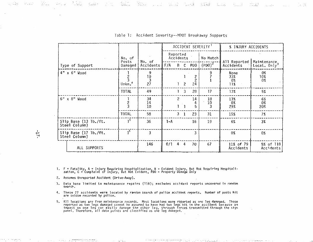
Analysis: Results of the accident analysis are presented in Table l. Across the board, performance of these sign supports is outstanding. For the 79 accidents reported to the police, only 9 (11%) resulted in an injury. Only one accident resulted in a serious injury requiring hospitalization. There were no deaths. The impacting vehicle rolled or flipped at only four of these locations due to the sign support, and in two of these cases, the vehicle was spinning prior to impact, causing it to hit the sign support sideways or backwards.
As previously noted, and even though the above analysis yields good results, it is still too conservative. By limiting a data base to accident-reported locations only, no credit is given to these supports for accidents in which the impact is so mild as to go unreported to the police.
I prefer to use the ''maintenance repair" data base, and assume that unmatched accidents are drive-aways (POO). Using this approach, for the 118 locations repaired by MOOT Maintenance forces, only 6 injury accidents (5%) were located. Only the one accident resulted in hospitalization.
Looking at the individual supports, it appears that the slip base designs are very safe, with only one injury accident out of 39 locations (2.5%). That accident was at 90° to the functional plane of the slip base, and the injured driver was not wearing a seat belt. About half the slip base accidents in this study occurred to predecessor designs used by MOOT. These predecessor designs varied chiefly in the use of smaller base bolts (5/8" D), which would result in about 20% more clamping force than the current designs. The predecessor to the W8 x 18 steel column was 8WF17, which weighs one pound per foot less as the classification indicates. Four of these accidents (all POO) occurred to slip bases installed or repaired in 1985-86, in which the slip base bolts may have been tightened by turn-of-the-nut.
-16-
:; i
., . '
I ..... " '
Table 1: Accident Severity--MllOT Breakaway Supports
No. of Posts No. of
Type of Support Damaged Accidents ==========================-f========f========= 4" x 6" Wood l 9
2 ltl 3 3
Unkn.4 27
TOTAL 49 -------- ----------
6 11 x 8 11 Wood l 34 2 14 3 10
-------- ---------TOTAL 58 -------- ---------15 36
ACCIDF:NT SEVERITY 1 % JN,JURY ACCIDENTS ------------------------- -----------------------------
Reported Accidents No Match
All Reported Maintenance3 Accidents · Locat. Only
================-======== -=============f============= l
l 2
l 3
2 2
24
28 ----------------
2 14 4
l l 5 ----------------3 1 23 ----------------1-A 16
3
0/l 4 4 70
9 7 1
17 --------
18 10
3 --------
31 --------
19
None 0% 33% 10%
0% 0% ll%
13% 5%
13% 6% 0% 0%
29% 20%
15% 7%
6% 3%
0% 0%
67 11% of 79 Accidents
5% of 118 Accidents
1. F =Fatality, A= Injury Requiring Hospitalization, B =Evident Injury. But Not Requiring Hospitalization, C = Complaint of InJury, But Not Evident, PDO = Property Damage Only
2. Assumes Unreported Accident (Drive-Away).
3. Data base limited to maintenance repairs (118); excludes accident reports uncovered in random search.
4. These 27 accidents were located by random search of police accident reports. Number of posts hit are seldom recorded by police.
5. All locations are from maintenance records. Most locations were reported as one leg damaged. Those reported as two legs damaged cannot he assumed to have had two legs hit in the accident because an impact on one leg car easily damage the other leg, through forces transmitted through the sign panel. Therefore, all data points are classified us one leg damagerl.
The 4'' x 6'' wood posts are extremely safe if you could limit the impact to only one post. In reality though, these posts are used on relatively small signs, and more often than not 2 or 3 posts are impacted in an accident (13 multi-post hits out of 22 in the maintenance data base). Nevertheless, even when impacts with multiple supports are considered, these posts perform very well. For all 4" x 6" wood post accidents in the maintenance data base, only one accident resulted in injury, and that was a 2-post impact. Nine other 2-post impacts, and three 3-post impacts did not result in injury.
According to the data in this report, the 6" x 8" wood posts accidents are more likely to be single-post rather than multi-post events. For the 34 locations in which a single 6" x 8" post was struck, only 2 accidents resulted in injury. For the 14 locations in which 2 posts were struck, there were no injuries. Finally, for 10 locations at which 3 posts were damaged, there were 2 injuries; however, the percentage of drive-aways at these 3-post installations is much smaller than seen for the 1 and 2-post installations.
Seat Belt Usage: When seat belt usage is considered, the performance of these supports is even more impressive. In five of the nine injury accidents, including the one serious injury, the injured person(s) was not protected by a seat belt. In the 78 accidents for which seat belt usage-r5 recorded, 63 drivers and 22 passengers are recorded as being seat belted. Only 6 of these 85 individuals (7%) were injured.
This analysis regarding seat belt usage must be viewed in context of State law. Michigan law allows police to assess a fine for failure to wear a seat belt, as a secondary offense. The seat belt usage rate recorded for drivers in this study is 81%, compared to statewide survey data (17) that shows only 54% usage for front seat occupants (mostly drivers-y-:--It is probable that some of the drivers who later reported to police that they had their seat belt engaged at the time of the accident, in fact did not have it engaged.
Small Car Performance: By means of a special MOOT computer program, the Vehicle Identification Number (VIN) was accessed to determine vehicle weight for each reported accident. Thirteen subcompacts (weight range 2051-2203 lbs.) were identified. Performance of the sign supports in these accidents is of special interest because the small car is the design vehicle for breakaway support testing.
Four of the 13 accidents resulted in injury, which is a higher percentage than for other vehicles; however, that is to be expected. Three of those four injury accidents occurred to drivers or occupants who were not seat belted, so the accident severity for seat-belted small car occupants is actually much better. Only 1 of these 13 cars rolled due to impact with the sign support.
-18-
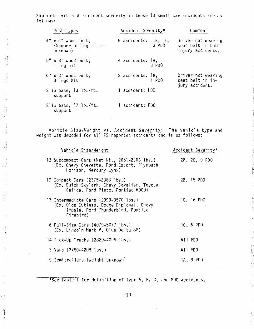
Supports hit and accident severity in these 13 small car accidents are as follows:
Post Types Accident Severity* Comment
4'' x 6'' wood post, (Number of legs hit-unknown)
5 accidents: lB, lC, Driver not wearing 3 PDO seat belt in both
injury accidents.
6" x 8'' wood post, 1 leg hit
6'' x 8" wood post, 3 legs hit
Slip base, 13 lb./ft. support
Slip base, 17 lb./ft. support
4 accidents: lB, 3 PDO
2 accidents: lB, 1 PDO
1 accident: PDO
1 accident: PDO
Driver not wearing seat belt in injury accident.
Vehicle Size/Weight vs. Accident Severity: The vehicle type and weight was decoded for all 79 reported accidents and is as follows:
Vehicle Size/Weight
13 Subcompact Cars (Net Wt., 2051-2203 lbs.) (Ex. Chevy Chevette, Ford Escort, Plymouth
Horizon, Mercury Lynx)
17 Compact Cars (2375-2888 lbs.) (Ex. Buick Skylark, Chevy Cavalier, Toyota
Celica, Ford Pinto, Pontiac 6000)
17 Intermediate Cars (2990-3570 lbs.) (Ex. Olds Cutlass, Dodge Diplomat, Chevy
Impala, Ford Thunderbird, Pontiac Firebird)
6 Full-Size Cars (4079-5077 lbs.) (Ex. Lincoln Mark V, Olds Delta 88)
14 Pick-Up Trucks (2829-4096 lbs.)
3 Vans (3750-4208 lbs.)
9 Semitrailers (weight unknown)
Accident Severity*
2R, 2C, 9 PDO
28, 15 PDO
lC, 16 PDO
lC, 5 PDO
All PDO
All PDO
lA, 8 PDO
*See Table 1 for definition of Type A, B, C, and PDO accidents.
-19-
In 27 of these accidents, the vehicle was spinning or sliding out of control, often on ice or snow-covered road, causing it to hit the sign support(s) in a position other than head-on. In two non-freeway accidents, a semi and a pick-up truck crossed a narrow median, crossed the opposing lanes, and hit a W8 x 13 column on slip base at 90° and 135° to the intended plane of operation, respectively. The pick-up driver was unhurt; the semi driver sustained the only serious (A) injury of the study, and that was complicated by a 90° entry into a ditch after striking the sign support.
Sign Type/Location/Lateral Offset: All 146 locations in the accident data base are multi-post installations. Only six of these locations are non-freeway, the rest being freeway. Most, but not all, of the signs were on the right side of the road, as opposed to median side.
Most 4" x 6" wood post installations in this study were exit gore signs (28), speed limit signs (7), or gas-food-lodging signs (7). The slip base installations were mostly advance guide signs (20) or exit direction signs (12). The 6" x 8" wood post installations were mostly advance guide signs (16), exit direction signs (14), supplemental guide signs (12) or rest area signs (6).
Lateral offset was not collected for the damaged signs in this study. However, exit gore signs in Michigan are typically 12'-16' off the edge of pavement. The larger signs are typically offset 20' when placed on 4'' x 6'' posts, and offset 30' when placed on 6" x 8" posts or slip bases. These offset dimensions are to the edge of sign, so the offset to closest post face would be greater.
From a review of the individual data points, it is evident that a greater lateral offset to these signs (say, additional 10 feet) would not necessarily have prevented all these accidents. Where only 1 support was damaged and was identified (68 locations), it was the support closest to the road only 59% of the time. For 37% of these locations, the damaged post was the one furthest from the road; at 3 locations (4%) the middle post of a 3-post support was damaged.
Accident Circumstances: Contributing):/uses to each accident were recorded from the pol ice accident report for ~,§?reported accidents, and are summarized here. Some of these categories overlap, such as "icy/snowy" and ''swerved to avoid another vehicle.'' These circumstances have no bearing on sign support performance, but are offered as a matter of interest:
Icy/Snowy 31 Driver Asleep 14 Swerved to Avoid Another Vehicle 10 Had Been Drinking 12 Heavy Rain 6 Fog 3 High Wind 3 Swerved to Avoid Deer, Dog 3 Overshot Exit 2 Steering Wheel Locked 2
Other contributing causes (1 each) were listed as follows: Driver inattentive; water puddle in road; object dropped off overpass; shouTder drop-off; tire blowout; driver blinded by sun; driver reached over to pick up cigarette: loss of control--pick-up towing two trailers.
-20-
CONCLUSIONS
MOOT has five separate designs for breakaway or yielding sign supports that are in common usage throughout the State:
4 11 X 6 11
6 11 X 8 11
W8 X 13 W8 X 18
3 lb./ft.
wood post wood post steel column on horizontal slip base steel column on horizontal slip base (prior design 8WF17) steel U-channel
Performance of the wood posts and steel column supports was investigated for this report and is determined to be excellent. Discussions with maintenance personnel indicate that the larger posts are fracturing (wood) or separating (steel) as intended under vehicle impact. A review of 146 accidents over the last 3 1/2 years confirms that occupant injury occurs in only about 5% of all accidents with these supports (ll% of reported accidents).
This outstanding performance record relates, of course, to the total range of vehicles on the road. AASHTO design standards are always based on the lightest weight vehicle,the most recent (1985) standards being based on the 1800 lb. subcompact car. Both of MOOT's steel column designs and the 3-lb. steel U-channel meet this new breakaway criteria. The wood posts have not yet been tested for compliance, although testing is planned. The critical point to be determined by this testing is whether two wood posts of either size should be permitted in a 7-foot path, based on measured change in velocity. Accident results from this study indicate that such a design is relatively safe.
MOOT's current practice of permitting three wood posts of either size within a 7-foot path should be discontinued, based on current (1975) AASHTO design standards, The 1977 pendulum testing on MOOT's wood post designs contained some subtleties which were not fully appreciated by FHv/A and MOOT at the time. In further review of that testing, these posts are not quite as forgiving as had been assumed and an impact with three posts would result in change of velocity exceeding current guidelines.
For the last several years, MOOT's contractors and maintenance personnel have been tightening slip base bolts by the turn-of-the-nut method. All slip bases tightened by this method have apparently been over-tightened, resulting in 8-to-10 times the amount of clamping force as intended in the MOOT slip base designs. Performance of these installations under vehicle impact is unknown, although four of the slip bases in this accident review may have been tightened by turn-of-the-nut. Nevertheless, these slip base installations must be considered hazardous based on the extreme amount of clamping force which has been developed. MDOT should take immediate action to lessen the base clamping force on these installations.
Prior to 1985, MOOT tightened slip base bolts by means of a torque wrench. This method is unreliable on galvanized fasteners used in weak connections. Tightening with a torque wrench tends to under-tighten these galvanized
-21-
bolts and probably contributed, to some extent, to MOOT's early wind-damage problems. It was this continuing difficulty with the torque wrench method that led MOOT to the use of the turn-of-the-nut method. It appears that neither tightening method is suitable to MOOT's slip base design, as long as the fasteners are galvanized. However, a design change to stainless steel bolts and nuts would allow a return to torque-wrenching, and is recommended. Another alternative that MDOT might want to explore is use of torque-controlling washers.
Most of the MOOT designs also require additional minor modifications to assure that once a sign support is displaced, the impacting vehicle can proceed through without snagging the undercarriage or the top of the vehicle on the remains of the sign installation.
The AASHTO and FHWA guidelines on slip base design would probably benefit from a careful review. The guidelines suggest a link between applied torque and resulting clamping force, without regard to bolt material and lubrication; however, these factors are important and the torque/clamping force relationship will vary widely depending on them. The guidelines also appear to be developed based on non-lubricated galvanized bolts, whereas lubrication of galvanized bolts is common practice and in fact recommended by the American Institute of Steel Construction. Finally, perhaps most important, the guidelines assume a predictable relationship between torque and clamping force for galvanized fasteners, whereas the experience at least in Michigan indicates that any such relationship is highly variable for weak connections as used in slip bases.
One logical implication of the preceding paragraph is that the national experience on slip base design may be -misrepresented. Any slip base design that faithfully follows the national recommendations on torque, but departs from the non-lubricated galvanized bolt concept should result in more clamping force on the base than indicated in the national guidelines, possibly twice as much. It is conceivable that a careful review of current and past designs across the nation could establish that slip bases have been performing satisfactorily for years at clamping forces well in excess of the current guidelines. MDOT practice, in this regard, has usually been to lubricate the slip base bolts with beeswax.
-22-
RECOMMENDATIONS
Based on the findings of this report, the following actions are recommended to modify the MOOT designs to meet current or proposed national criteria:
Wood Post Designs:
1. To comply with current national criteria, MOOT should revise their current guidelines so as not to allow three wood posts (of either size) within a 7-foot path.
2, Dynamic testing (test car, bogie vehicle or pendulum) should be conducted on both sizes of wood posts with an 1800 lb. vehicle. Posts selected for testing should be of species and grade to represent the strongest wood which MOOT expects to be supplied under their forthcoming specification change. Tested posts should also be treated with preservative according to the forthcoming specification. MOOT has contracted with FHWA in a pooled fund study that hopefully will test these MOOT designs.
3, The lower hole on the 6'' x 8'' post design (Standard Plan S3-30A) should be lowered such that the centerline of the hole is approximately 4'' above ground, or the design should be crash-tested (test car or bogie vehicle) to determine height of stub remaining after impact.
Slip Base Designs
4. Standard Plan VIII-44 should be revised to provide a design that can be reliably constructed to produce MOOT's desired clamping force. One alternative is to require that the slip base bolts be made of stainless steel, rather than galvanized steel as currently specified. Another approach that MOOT might want to pursue is the use of torquecontrolling washers. The plan should further specify how the design torque is to be achieved in the field (e.g. torque wrench).
5. MOOT should re-torque all slip base bolts which have been tightened by the turn-of-the-nut method in the last several years. The re-torquing should be by use of a torque wrench, to assure that a torque no greater than 38 ft.-lbs. is being applied. Because this could result in under tightening of the existing galvanized bolts and subsequent wind damage, it is further recommended that the design change(s) recommended in No.4 (above) be added to these slip bases at the time of theretorquing.
6, If MOOT chooses to require stainless steel bolts, tests should be run at the Material Research Laboratory to determine the torque/bolt tension relationship in such bolts. Based on this testing, MOOT should specify a design torque that will produce a bolt tension (clamping force) in the 1740-2660 lb. range recommended by current national guidelines. If, after observing the clamping force produced by the true 2660 lb. bolt tension, MOOT personnel feel greater clamping force is desired, the design clamping force could be increased, as needed, with corresponding increase in design torque. The national guidelines need not be considered sacred here: They are based on calculations and laboratory testing only; therefore, they may not accurately model the long-term effects of wind. Also, MOOT's current design clamping force, though slightly higher than the national guidelines, is well within the range of similar designs which have been crash-tested successfully with an 1800 lb. vehicle.
-23-

7. MDOT should consider a .design change in Standard Plan VIII-44 to specify a thinner steel in the keeper plate.
8. Standard Plan VIII-44 should be revised to require Grade A36 steel for the tension fuse plate (ruling out other options currently allowed).
9. One other option regarding the tension fuse plate could be considered by MOOT, but is not necessarily recommended here: The cross-sectional area through the plane of weakness could be reduced by 20%, to match the TTl design. This would be desirable if, in the future, MDOT determines that the fuse plate is not breaking as intended under impact (perhaps small car impacts). For the current mix of vehicles, as determined in this report, the current fuse plate seems to be performing well enough.
10. Standard Plans VIII-44 and VIII-45 should be modified to reduce the height of stub and concrete foundation when installed on slopes.
Frangible Coupling Design:
11. Standard Plan VIII-100 should be modified to reduce the height of stub and concrete foundation when installed on slopes.
Multi-Post Breakaway Designs (Wood Post, Slip Base, Frangible Coupling):
12. These designs should be modified to require 7' minimum clearance from ground to upper hinge. The saw cut on wood posts, currently specified to be 6'' below the bottom of the sign panel, could be moved closer to the sign panel as part of this modification.
13. These designs should be modified to require 7' minimum clearance from the ground to the bottom of the sign panel, for the entire width of the sign panel. Circumstances which would warrant a lesser underclearance could be put forth in a general note on the Standard Plan Index, as is currently done. However, the current note should be more specific to ensure that this design goal is compromised only when other design goals (lateral offset, maximum viewing height) cannot be compromised beyond a certain value.
14. MOOT should consider placing a maximum dimension on height of upper hinge, to limit the weight of displaced post during impact.
Single Post Designs (Wood Post, Steel U-Channel):
15. These designs should be modified to show a minimum 6' or 7' clearance from ground to bottom of sign panel, when used along high-speed roadways.
-24-
Performance Monitoring:
16. MOOT should consider modifying their current tracking procedure for accident-damaged large sign supports, so that one file would contain the type of sign support hit and the resulting police accident report (if any). One easy way to reach this goal, within the existing tracking system, is to require positive accident data feedback within the Maintenance Division, from the Resource Control Unit to the Overhead Sign Unit, on all Memorandum Job Reports submitted for sign supports.
Construction Inspection:
17. MOOT should issue updated instructions to Construction Division field personnel regarding proper construction and inspection of the slip base designs.
Design Procedure
18. MDOT should formalize the process for developing and maintaining the Signing Standard Plans which currently exist in the Traffic and Safety Division. This process should include submittal to FHWA for approval as Standard Plans.
National Design Guidelines
19. The national guidelines for slip base design should be reviewed by AASHTO and FHWA in light of the findings and conclusions contained in this report.
-25-
REFERENCES
1. 'Pendulum Tests of Breakaway Wood Signs Supports,'' Southwest Research Institute, Final Report, Project 03-4685-206, July, 1977.
2. 'Laboratory Evaluation of Existing Breakaway Structures,' FHWA Report No. FHWA-RD-79-140, June, 1980.
3. 'Crash Tests of Small Highway Sign Supports,' FHWA Report No. FHWA/RD-80/502, May, 1980.
4. 'Design Criteria for Breakaway Sign Supports,' Highway Research Record No. 222, p. 12-18, 1968.
5. Buth, E., 'Bolt Torque, Bolt Tension and Slip Bases,' Texas Transportation Research Institute, December, 1974.
6. 'Sign Support Systems--Compliance with 1985 AASHTO Specification,' FHWA Memorandum from L. A. Staron, Chief, Federal-Aid and Design Division, June 15, 1987.
7. Proposed 'Roadside Design Guide,'' ballot draft, AASHTO, 1988.
8. 'Specification for Structural Joints Using ASTM A325 or A490 Bolts,' Manual of Steel Construction, pp. 5-209 to 5-229, American Institute of Steel Construction, Inc., 1980.
9. ''Relaxation of Bolt Tension in Galvanized High Strength Steel Bolted Connections,'' MOOT Memorandum from R. L. Rung, Engineering Technician, Aggregate and Metals Laboratory, MOOT Materials and Testing Division, January 13, 1985.
10. Haviland, Girard S., 'Designing with Threaded Fasteners,' Mechanical Engineering Magazine, October, 1983.
11. 'Full Scale Vehicular Crash Testing of a Modified NJ Breakaway Sign Structure,'' Southwest Research Institute, Final Report on Project 06-7729, November, 1983.
12. FHI~A Notice N 5040.20, 'Suggested Guidelines for Application of Breakaway Requirements of the AASHTO Standard Specifications for Structural Supports for Highway Signs, Luminaires, and Traffic Signals,' July 14, 1976.
-26-
. " .. -· . -- .. --. '- .-. -- ·c:~

13. "Investigation of Rigid Fuse Plates for Use on Breakaway Signs," Michigan DOT Report No. R-652, November, 1967.
14. "Perforated Tension Fuse Plate for Breakaway Roadside Signs," Texas Transportation Institute, Report 343-3F, October, 1984.
15. Comments on Draft Final Report No. 343-3F, "Perforated Tension Fuse Plate for Breakaway Roadside Signs," Charles McDevitt, FHWA Office of Safety and Traffic Operations Research and Development, Safety Design D i vi s i on, 1984.
16. "Luminal re and Sign Supports, Tests Nos. 5, 6, 7, and 8 (Wisconsin Stiff Leg Sign Support), Test Reports," Mobility Systems and Equipment Company Reports Nos. MSE/R 8006-l, 2, 3, and 4, June, 1988.
17. "Direct Observation of Seat Belt Use in Michigan: Spring, 1988," University of Michigan Transportation Research Institute, July, 1988.
-27-


![INDEX [] · iso 5675 push pull coupling ( with bulkhead) push pull agri series 71 8 iso 5675 breakaway coupling breakaway series 73 iso 5675 breakaway coupling (with male end ) breakaway](https://static.fdocuments.us/doc/165x107/5c168d0809d3f29f108cc8b6/index-iso-5675-push-pull-coupling-with-bulkhead-push-pull-agri-series.jpg)