RQ-5000E ROBOTIC NOZZLE CLEANING STATION · All Semi-Automatic, Automatic, Robotic MIG TORCHES and...
32
ROBO-QUIP RQ-5000E ROBOTIC NOZZLE CLEANING STATION ETHERNET/ PROFINET IP VERSION INSTALLATION, OPERATIONS AND REPLACEMENT PARTS MANUAL
Transcript of RQ-5000E ROBOTIC NOZZLE CLEANING STATION · All Semi-Automatic, Automatic, Robotic MIG TORCHES and...
0
ROBO-QUIP
RQ-5000E ROBOTIC
NOZZLE CLEANING
STATION
ETHERNET/ PROFINET IP
VERSION
INSTALLATION, OPERATIONS AND REPLACEMENT PARTS MANUAL
1
TABLE OF CONTENTS
INTRODUCTION/WARRANTY ....................................................................................................................................... 1
ROBO-QUIP SPECIFICATIONS ...................................................................................................................................... 2
SAFETY INSTRUCTIONS ............................................................................................................................................... 3
FEATURES ............................................................................................................................................................... 7
INSTALLATION AND SETUP .......................................................................................................................................... 8
REAMER BLADE SELECTION CHART ............................................................................................................................. 10
COMMISSIONING,CONFIGURATION AND PARAMETERIZATION .......................................................................................... 12
OPERATION ........................................................................................................................................................... 17
TROUBLESHOOTING ................................................................................................................................................ 17
MAINTENANCE....................................................................................................................................................... 21
WIRE CUTTER INSTALLATION .................................................................................................................................... 24
WIRING DIAGRAM/PNEUMATIC DIAGRAM ........................................................................................................... 25- 26
PART LIST – ROBO-QUIP .................................................................................................................................... 27-28
INTRODUCTION
Thank you for purchasing an American Weldquip product. The American Weldquip product you have purchased
has been carefully manufactured, assembled and fully tested. This manual contains information on the
installation, operation, maintenance and replacement part breakdown. Please read, understand and follow all
safety instructions, warnings and procedures. Keep this manual handy for referencing installation, operation,
maintenance and part ordering information. While every precaution has been taken as to the accuracy in this
manual, American Weldquip, Inc. assumes no responsibility for errors or omissions. American Weldquip, Inc.
assumes no liability for damages resulting from the use of the information contained in this manual. American
Weldquip, Inc. shall have no liability to the buyer for consequential damages or expenses by any defect
whatsoever.
WARRANTY
AMERICAN WELDQUIP MIG guns and parts are warranted to be free of defects in material and/or workmanship for the period
of time listed below. For any product found to be defective under normal use, AMERICAN WELDQUIP, INC. at our option, will
repair, replace or issue a credit for the value of the defective product. All warranty claims must be submitted by the original
purchaser. Use of non-genuine AMERICAN WELDQUIP parts and/or consumables may damage and/or severely limit the
performance of the equipment which may limit or void any warranties. AMERICAN WELDQUIP, INC. will not assume
responsibility for incidental damages or expenses related to any defect. This warranty does not cover damage caused by misuse
or abuse, accident, alteration of product, improper installation, misapplication, lack of reasonable care and maintenance,
unauthorized repairs or modifications, loss of use while at a repair facility or other conditions that are beyond the control of
American Weldquip, Inc.
A Return Authorization Number (RA#) must be attained from the factory for any product being returned for Warranty Repair or
Replacement. All returned product must be shipped freight prepaid by the sender. No- charge replacements, repaired
products, or credit will be issued, once the returned product has been evaluated and warranty condition has been verified. If an
immediate replacement is required before proper warranty evaluation, a purchase order number is required and the goods will
be invoiced. A credit will be issued once it is determined that a warranty condition exists.
STANDARD WARRANTY
All Semi-Automatic, Automatic, Robotic MIG TORCHES and Components = 120 Days
MIG Torch Trigger Switches (Contacts only) -Excludes Smoke Extraction = LIFETIME
Robotic Nozzle Cleaning Stations, Wire Cutter = 6 Months**
Robotic Peripherals, ArcSafe, Gun Mounts = 90 Days
TIG POINT Tungsten Electrode Grinders = 90 Days
2
LIMITED EXTENDED WARRANTY PROTECTION
This limited extended warranty protection expands coverage to loyal customers who use all GENUINE American Weldquip
consumables. Customers filing a claim under the extended warranty will need to prove, by providing past invoices, that they
have been purchasing and using Genuine American Weldquip consumables.
All Semi-Automatic, Automatic, Robotic MIG TORCHES and Components = 1 YEAR
MIG Torch Trigger Switches (Contacts only) -Excludes Smoke Extraction = LIFETIME
MIG Torch Handles = LIFETIME
Robotic Nozzle Cleaning Stations, Wire Cutter = 1 Year w/Exclusive Quip-Mist Use
Robotic Peripherals, ArcSafe, Gun Mounts = 90 Days
TIG POINT Tungsten Electrode Grinders = 90 Days
ROHS COMPLIANT
RoHS (Restriction of Hazardous Substances) is an environmental law which addresses the European Union directive 2002/95/EC known as the RoHS Directive. The RoHS directive restricts the use of hazardous substances listed below in electrical and electronic equipment. While it is not a requirement to meet the directive in the United States, at this time, American Weldquip Inc. feels this is an important part of our “Go Green initiative. We have taken all reasonable steps to try to insure the supporting evidence regarding the absence of the restricted substances to support RoHS compliance. For reference, the maximum concentration values of the restricted substances by weight in homogenous materials are: Lead/Lead Components - 0.1% Mercury - 0.1% Hexavalent Chromium - 0.1% Polybrominated Biphenyls (PBBs) - 0.1% Polybrominated Diphenyl Ethers (PBDEs) - 0.1% Cadmium -0.01% For RoHS Certification of Compliance Letter on a particular product please visit our website – www.weldquip.com or email us at [email protected] or call 330-239-0317.
SPECIFICATIONS
Air Requirements – 80-120 PSI @ 8 S.C.F.M (Min) Clean Shop Air Reamer Stroke – 2” (50.8mm) Dimensions – 8 ½” (215.9mm) L x 8” (203.2mm) W x 11.5” (292.1mm) H Weight – Robo-Quip Station – 29.65 Lbs. (13.449Kg) Electrical - (3) Robot Outputs and (1) Robot Input Required Output: 0VDC Switchable Ground Output: 24 VDC Continuous Supply Input: 24 VDC Signal Return
3
SAFETY PRECAUTIONS – READ BEFORE USING
Before installing, operating or performing maintenance please read the safety precautions below. Failure to observe safety precautions can result in injury or death.
Read and follow the Owner’s Manual carefully before installing, operating or servicing equipment. Read and understand all safety information.
CALIFORNIA PROPOSITION 65 WARNINGS This product, when used for welding and cutting, can produce fumes or gases which contain chemicals known to cause birth defects and cancer. (California Health & Safety Code Section 25249.5 et seq.)
EMF – ELECTRICAL AND MAGNETIC FIELDS MAY BE DANGEROUS Electrical current flowing through any conductor causes localized Electric and Magnetic Fields(EMF). Welding current creates and EMF field around welding cables and welding machines.
WARNING - EMF fields may interfere with some pacemakers and other medical implants. Implanted medical device wearers should consult their doctor before operating or going near any arc welding applications. In addition, exposure to EMF fields in welding may have other unknown health effects.
Welders should use the below procedures to minimize the exposure to EMF fields from the welding circuit.
1) Route the cables close together. Secure by twisting, taping or using a cable cover to keep together.
2) Never coil, wrap or drape welding cables around your body.
3) Do not place your body between welding cables. Arrange so that cables are on one side and away from the operator.
4) Connect the work clamp(ground) to the workpiece as close as possible to the area to be welded.
5) Do not sit, lean and stand next to the welding power source.
FUMES AND GASES CAN BE DANGEROUS
WARNING - WELDING AND CUTTING PRODUCE FUMES AND GASES THAT ARE HAZARDOUS TO YOUR
HEALTH
1) Do not breathe the fumes and gases as they can cause asphyxiation.
2) Fumes and gases generated from welding can cause severe injury to respiratory system and even death. In poorly vented areas it is required to properly ventilate the area and/or use local forced ventilation or other fume control equipment at the arc to remove welding and cutting fumes and gases.
3) The recommended way to determine adequate ventilation is to sample for the composition and quantity of fumes and gases to which personnel are exposed. The worker exposer level should be checked initially and periodically thereafter to maintain applicable OSHA PEL and ACGIH TVL limits.
4) In a poorly ventilated area it is necessary to wear an approved air-supplied respirator.
5) Always read and understand the Safety Data Sheets (SDSs) and the manufacturer’s instructions for adhesives, coatings, cleaners, consumables, coolants, degreasers, fluxes and metals.
6) Always have a trained watch-person nearby. Welding and cutting fumes and gases can displace air and lower the oxygen level causing injury or death. Be sure the breathing air is safe.
7) Do not weld or cut in locations near degreasing, cleaning, or spraying operations. The heat and rays of the arc can react with vapors to form highly toxic and irritating gases.
8) Do not weld or cut on coated metals, such as galvanized, lead, or cadmium plated steel, unless the coating is removed from the weld area, the area is well ventilated, and while wearing an air-supplied respirator. The coatings and any metals containing these elements can give off toxic fumes if welded.
4
ELECTRIC SHOCK CAN KILL
WARNING - ELECTRICAL SHOCK CAN KILL. DO NOT TOUCH LIVE ELECTRICAL PARTS AND/OR USE IN
DAMP LOCATIONS.
1) The electrode and work (ground) circuit is electrically “HOT” whenever the welding equipment is on. Do not touch these electrically live parts with your bare skin or wet/damp clothing. Wear dry, hole-free gloves. Incorrectly installed or improperly grounded equipment is a hazard.
2) Insulate yourself from work and ground using dry insulating mats or covers big enough to prevent any physical contact with the work or ground.
3) Additional safety precautions are required when any of the following electrically hazardous conditions are present: in damp locations or while wearing wet clothing; on metal structures such as floors, gratings or scaffolds; when in cramped positions such as sitting, kneeling or lying; or when there is a high risk of unavoidable or accidental contact with the workpiece or ground. For these conditions, use the following equipment in order presented: 1) a semi-automatic DC constant voltage, 2) a DC manual (stick) welder or 3) an AC welder with reduced open-circuit voltage. In most situations, use of a DC, constant voltage wire welder is recommended and do not work alone!
4) Disconnect input power or stop engine before installing or servicing this equipment. Lockout/tag out input power according to OSHA 29 CFR 1910.147 (see Safety Standards).
5) Properly install ground and operate this equipment according to its Owner’s Manual and national, state/provincial and local codes.
6) Always verify the supply ground. Make sure that input power cord ground wire is properly connected to ground terminal in disconnect box or that cord plug is connected to a properly grounded receptacle outlet.
7) Keep cords dry, free of oil and grease and protected from hot metal and sparks.
8) Frequently inspect input power cord for damage or bare wiring. Replace cord immediately if damaged. Bare wiring can kill.
9) Turn off all equipment when not in use.
10) Do not use worn, damaged, undersized or poorly spliced cables. It is illegal to use electrical tape to repair torch power cable or ground cable that has damaged outer insulation. The cable must be replaced.
11) Do not drape cables over your body.
12) Do not touch electrode if you are in contact with the work, ground or another electrode from a different machine.
13) Do not touch electrode holders connected to two welding machines at the same time since double open circuit voltage will be present.
14) Use only well maintained equipment. Repair or replace damaged parts at once. Maintain unit according to manual.
15) Wear a safety harness if working above floor level.
16) Keep all panels and covers securely in place.
17) Clamp work cable with good metal-to-metal contact to workpiece or worktable as near the weld as practical.
18) Do not connect more than one electrode or work cable to any single weld output terminal. Disconnect cable for process when not in use.
ARC RAYS HAZARDS
WARNING – A WELDING ARC EMITS ULTRAVIOLET (UV) AND OTHER RADIATION AND
CAN CAUSE SERIOUS INJURY TO UNPROTECTED SKIN AND EYES.
1) Use a shield with the proper filter and cover plates to protect your eyes from sparks and the rays of the arc when welding or observing open arc welding. Headshield and filter lens should conform to ANSI Z87. I standards.
2) Use suitable clothing made from durable flame-resistant material to protect your skin and that of your helpers from the arc rays.
3) Protect other nearby personnel with suitable, non-flammable screening and/or warn them not to watch the arc nor expose themselves to the arc rays or to hot spatter or metal.
5
WELDING AND CUTTING CAN CAUSE FIRE OR EXPLOSION
WARNING – Welding and cutting produces sparks that fly off from the arc and can cause fires
and/or explosions.
1) Welding or cutting on closed containers, such as tanks, drums or pipes can cause them to blow up. Sparks can fly off from the welding or cutting arc. The flying sparks, hot work piece and hot equipment can cause fires and burns.
2) Accidental contact of electrode to metal objects can cause sparks, explosion, overheating or fire. Check and be sure the area is safe before doing any welding or cutting.
3) Do not weld or cut where flying sparks can strike flammable material.
4) Remove all flammables and fire hazards from the welding area. If this is not possible, tightly cover them with approved covers to prevent the welding sparks from starting a fire.
5) When not welding, make certain no part of the electrode circuit is touching the work or ground. Accidental contact can cause overheating and create a fire hazard.
6) Be alert that welding sparks and hot materials from welding and cutting can easily go through small cracks and openings and cause a fire in the adjacent areas.
7) Follow requirements in OSHA 1910.252 (a) (2) (iv) and NFPA 51B for hot work and have a fire watcher and extinguisher nearby.
8) Do not heat, cut or weld tanks, drums or containers that have held combustibles until the proper steps have been taken to insure that such procedures will not cause flammable or toxic vapors from substances inside. They can cause an explosion even though they have been “cleaned”. For information, purchase “Recommended Safe Practices for the Preparation for Welding and Cutting of Containers and Piping That Have Held Hazardous Substances”, AWS F4.1 from the American Welding Society .
9) Do not weld or cut where the atmosphere may contain flammable dust, gas, or liquid vapors (such as gasoline).
10) Sparks and spatter are thrown from the welding arc. Wear oil free protective garments such as leather gloves, heavy shirt, cuff-less trousers, high shoes and a cap over your hair. Wear ear plugs when welding out of position or in confined places. Always wear safety glasses with side shields when in a welding area.
11) Connect work cable to the work as close to the welding or cutting area as practical to prevent welding or cutting current from traveling long, possibly unknown paths and causing electric shock, sparks and fire hazards.
12) Do not use welder to thaw frozen pipes.
13) Remove any combustibles, such as a butane lighter or matches, from your person before doing any welding or cutting.
14) Inspect area to ensure it is free of sparks, glowing embers, and flames after work is complete.
CYLINDERS CAN EXPLODE IF DAMAGED
WARNING – Compressed gas cylinders contain gas under high pressure and/or flammable gas.
If damaged, the cylinder can explode.
1) Use only compressed gas cylinders containing the correct shielding gas for the process used and properly operating regulators designed for the gas and pressure used. All hoses, fittings, etc. should be suitable for the application and maintained in good condition.
2) Always keep cylinders in an upright position securely chained to an undercarriage or fixed support.
3) Cylinders should be located away from areas where they may be struck or subjected to physical damage and a safe distance from arc welding or cutting operations and any other source of heat, sparks, or flame.
4) Never allow the electrode, electrode holder or any other electrically “hot” parts to touch a cylinder.
5) Keep your head and face away from the cylinder valve outlet when opening the cylinder valve.
6
6) Valve protection caps should always be in place and hand tight except when the cylinder is in use or connected for use.
7) Read and follow the instructions on compressed gas cylinders, associated equipment, and CGA publication P-l, “Precautions for Safe Handling of Compressed Gases in Cylinders,” available from the Compressed Gas Association, 14501 George Carter Way Chantilly, VA 20151.
PRINCIPAL SAFETY STADARDS Safety in Welding, Cutting and Allied Processes, ANSI Standard Z49.1 – available for download from the American Welding Society website at www.aws.org.
CSA Standard W117.2 – available from Canadian Standards Association, Standards Sales, 5060 Spectrum Way, Suite 100, Ontario, Canada L4W 5NS or website – www.csa-international.org.
Nation Electric Code, NFPA Standard 70 – available from National Fire Protection Association, Quincy, MA 02269 or website – www.nfpa.org.
Safe Practices For Occupational And Educational Eye and Face Protection, ANSI Standard Z87.1 – available from the American National Standards Institute, 25 West 43rd Street, New York, NY 10036. Website – www.ansi.org.
OSHA, Occupational Safety and Health Standard for General Industry, Title 29, Code of Federal Regulations, Part 1910, Subpart Q and Part 1926, Subpart J available from U.S. Government Printing Office, Superintendent of Documents, P.O. Box 371954, Pittsburg, PA 15250. Wbsite – www.osha.gov.
7
RROOBBOO--QQUUIIPP RROOBBOOTTIICC NNOOZZZZLLEE CCLLEEAANNIINNGG SSTTAATTIIOONN
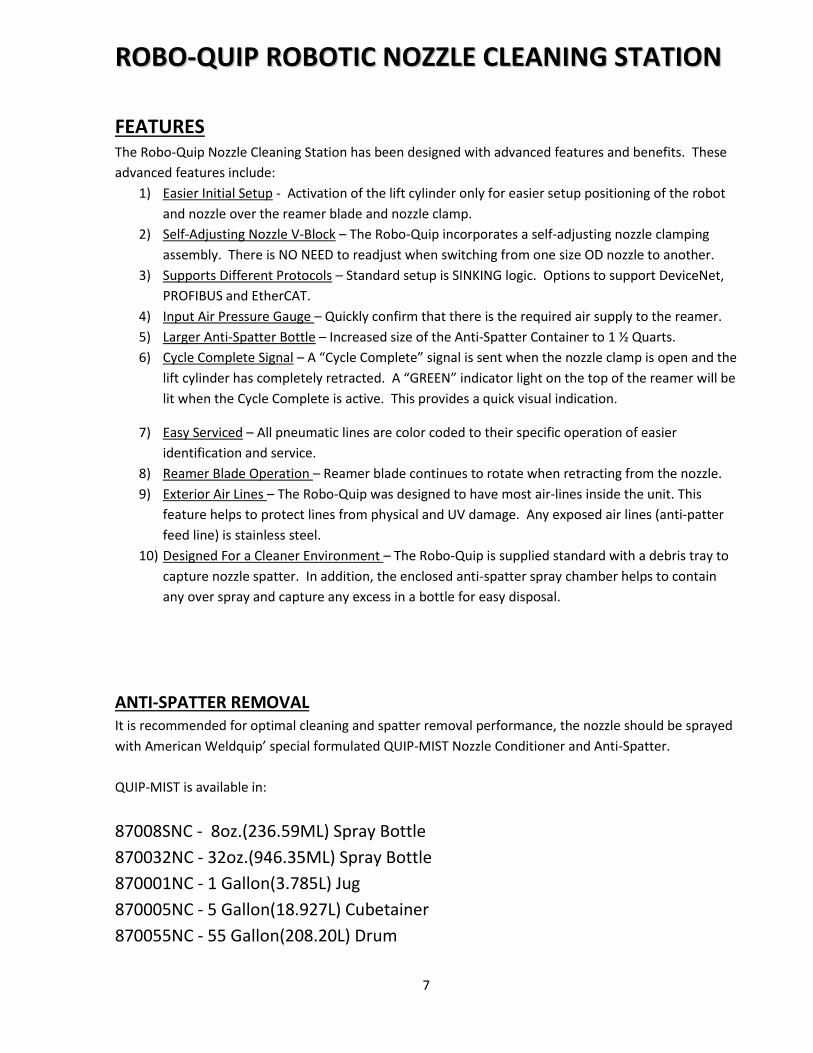
FEATURES The Robo-Quip Nozzle Cleaning Station has been designed with advanced features and benefits. These
advanced features include:
1) Easier Initial Setup - Activation of the lift cylinder only for easier setup positioning of the robot
and nozzle over the reamer blade and nozzle clamp.
2) Self-Adjusting Nozzle V-Block – The Robo-Quip incorporates a self-adjusting nozzle clamping
assembly. There is NO NEED to readjust when switching from one size OD nozzle to another.
3) Supports Different Protocols – Standard setup is SINKING logic. Options to support DeviceNet,
PROFIBUS and EtherCAT.
4) Input Air Pressure Gauge – Quickly confirm that there is the required air supply to the reamer.
5) Larger Anti-Spatter Bottle – Increased size of the Anti-Spatter Container to 1 ½ Quarts.
6) Cycle Complete Signal – A “Cycle Complete” signal is sent when the nozzle clamp is open and the
lift cylinder has completely retracted. A “GREEN” indicator light on the top of the reamer will be
lit when the Cycle Complete is active. This provides a quick visual indication.
7) Easy Serviced – All pneumatic lines are color coded to their specific operation of easier
identification and service.
8) Reamer Blade Operation – Reamer blade continues to rotate when retracting from the nozzle.
9) Exterior Air Lines – The Robo-Quip was designed to have most air-lines inside the unit. This
feature helps to protect lines from physical and UV damage. Any exposed air lines (anti-patter
feed line) is stainless steel.
10) Designed For a Cleaner Environment – The Robo-Quip is supplied standard with a debris tray to
capture nozzle spatter. In addition, the enclosed anti-spatter spray chamber helps to contain
any over spray and capture any excess in a bottle for easy disposal.
ANTI-SPATTER REMOVAL It is recommended for optimal cleaning and spatter removal performance, the nozzle should be sprayed
with American Weldquip’ special formulated QUIP-MIST Nozzle Conditioner and Anti-Spatter.
QUIP-MIST is available in:
87008SNC - 8oz.(236.59ML) Spray Bottle
870032NC - 32oz.(946.35ML) Spray Bottle
870001NC - 1 Gallon(3.785L) Jug
870005NC - 5 Gallon(18.927L) Cubetainer
870055NC - 55 Gallon(208.20L) Drum
8
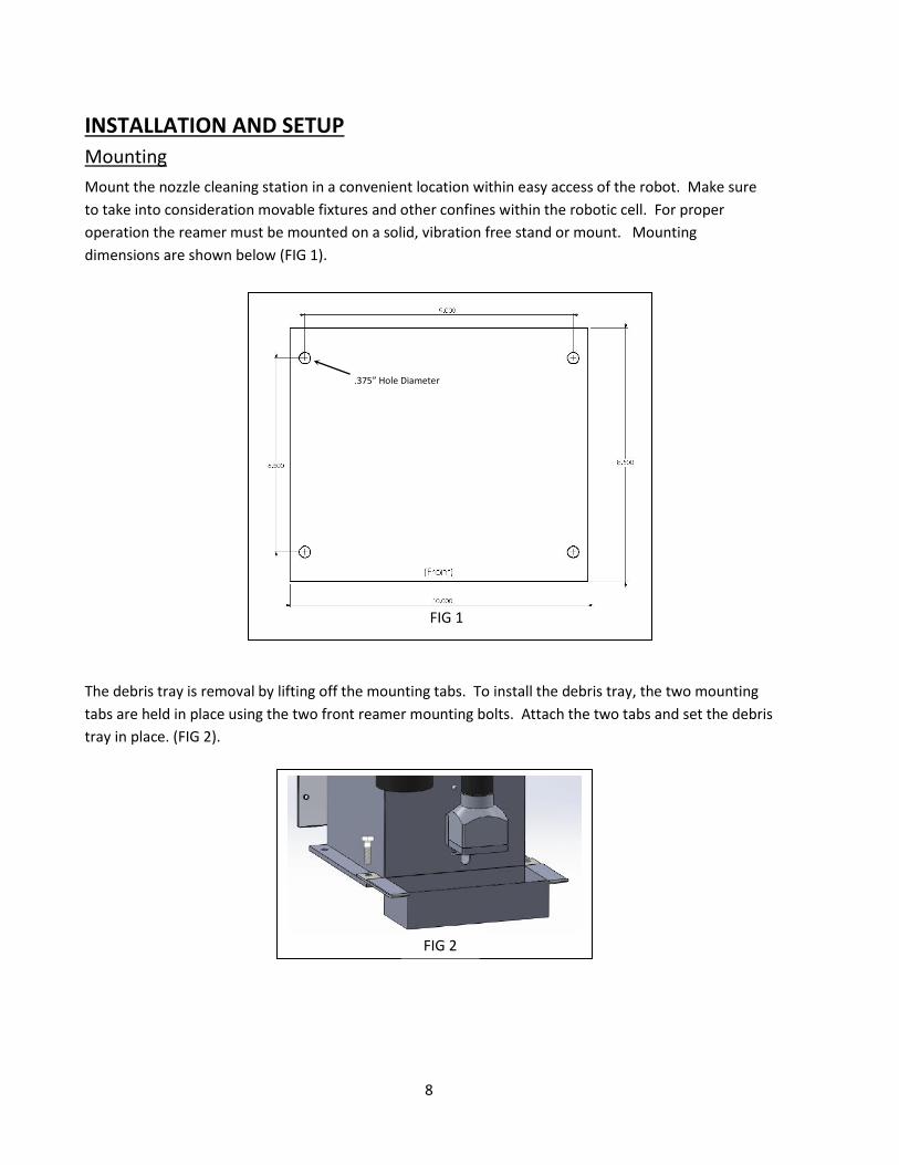
INSTALLATION AND SETUP
Mounting
Mount the nozzle cleaning station in a convenient location within easy access of the robot. Make sure
to take into consideration movable fixtures and other confines within the robotic cell. For proper
operation the reamer must be mounted on a solid, vibration free stand or mount. Mounting
dimensions are shown below (FIG 1).
The debris tray is removal by lifting off the mounting tabs. To install the debris tray, the two mounting
tabs are held in place using the two front reamer mounting bolts. Attach the two tabs and set the debris
tray in place. (FIG 2).
FIG 2
FIG 1
.375” Hole Diameter
9
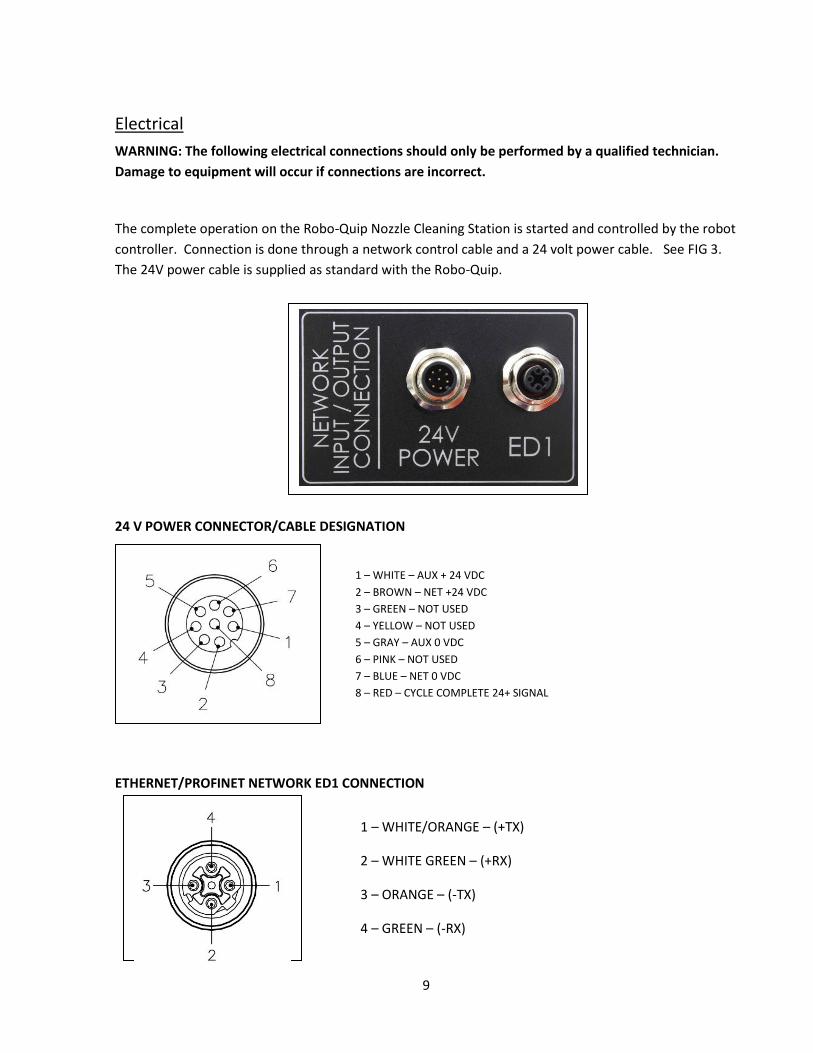
Electrical
WARNING: The following electrical connections should only be performed by a qualified technician.
Damage to equipment will occur if connections are incorrect.
The complete operation on the Robo-Quip Nozzle Cleaning Station is started and controlled by the robot
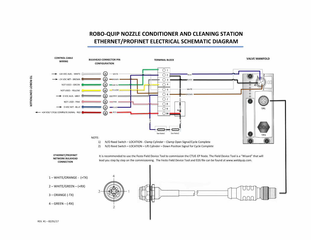
controller. Connection is done through a network control cable and a 24 volt power cable. See FIG 3.
The 24V power cable is supplied as standard with the Robo-Quip.
24 V POWER CONNECTOR/CABLE DESIGNATION
ETHERNET/PROFINET NETWORK ED1 CONNECTION
1 – WHITE – AUX + 24 VDC
2 – BROWN – NET +24 VDC
3 – GREEN – NOT USED
4 – YELLOW – NOT USED
5 – GRAY – AUX 0 VDC
6 – PINK – NOT USED
7 – BLUE – NET 0 VDC
8 – RED – CYCLE COMPLETE 24+ SIGNAL
1 – WHITE/ORANGE – (+TX)
2 – WHITE GREEN – (+RX)
3 – ORANGE – (-TX)
4 – GREEN – (-RX)
10
PA
RT
NU
MB
ER
NO
ZZLE
B
OR
E SI
ZE
OD
ID
L1
L2
THR
EAD
TY
PE
REA
MER
SP
ECIF
IC
RB500 1/2” (13mm) .490”(12.5mm) .374”(9.5mm) 2.56”(65mm) 1.75”(44.7mm) Female - 3/8-24
RB-500B 1/2” (13mm) .490”(12.5mm) .374”(9.5mm) 3.02”(76.7mm) 1.75”(44.7mm) Male – M24x1.5 Binzel
RB500-04TRG 1/2” (13mm) .490”(12.5mm) .374”(9.5mm) 1.65”(42mm) 1.10”(28mm) Male - 3/8-24 Tregaskiss
RB560 9/16” (15mm) .555”(14.1mm) .433”(11mm) 2.56”(65mm) 1.75”(44.7mm) Female - 3/8-24
RB560-01 9/16”(15mm) .535”(13.5mm) .393”(10mm) 1.65”(42mm) 1.10”(28mm) Female - 3/8-24
RB560-01B 9/16” (15mm) .535”(13.5mm) .393”(10mm) 2.11”(53.5mm) 1.10”(28mm) Male – M24x1.5 Binzel
RB560-01TRG 9/16” (15mm) .535”(13.5mm) .393”(10mm) 1.65”(42mm) 1.10”(28mm) Male - 3/8-24 Tregaskiss
RB625 5/8” (16mm) .610”(15.5mm) .511(13mm) 2.69”(68mm) 2.13”(54mm) Female - 3/8-24
RB625B 5/8” (16mm) .610”(15.5mm) .511(13mm) 3.152”(68mm) 2.13”(54mm) Male – M24x1.5 Binzel
RB625-01TRG 5/8” (16mm) .610”(15.5mm) .511(13mm) 2.69”(68mm) 2.13”(54mm) Male - 3/8-24 Tregaskiss
RB625-01 5/8” (16mm) .610”(15.5mm) .453”(11.5mm) 2.56”(65mm) 1.75”(44.7mm) Female - 3/8-24
RB625-02 5/8” (16mm) .610”(15.5mm) .511”(13mm) 2.95”(75mm) 2.14”(54mm) Female - 3/8-24
RB625-03 5/8” (16mm) .590”(15mm) .433”(11mm) 2.56”(65mm) 1.75”(44.7mm) Female - 3/8-24
RB625-03B 5/8” (16mm) .590”(15mm) .433”(11mm) 3.02”(71.4mm) 1.55”(39.4mm) Male – M24x1.5 Binzel
RB750 3/4” (19mm) .704”(17.9mm) ..508”(12.3mm) 2.56”(65mm) 1.75”(44.7mm) Female - 3/8-24
RB750-01TRG 3/4” (19mm) .704”(17.9mm) ..508”(12.3mm) 2.56”(65mm) 1.75”(44.7mm) Male - 3/8-24 Tregaskiss
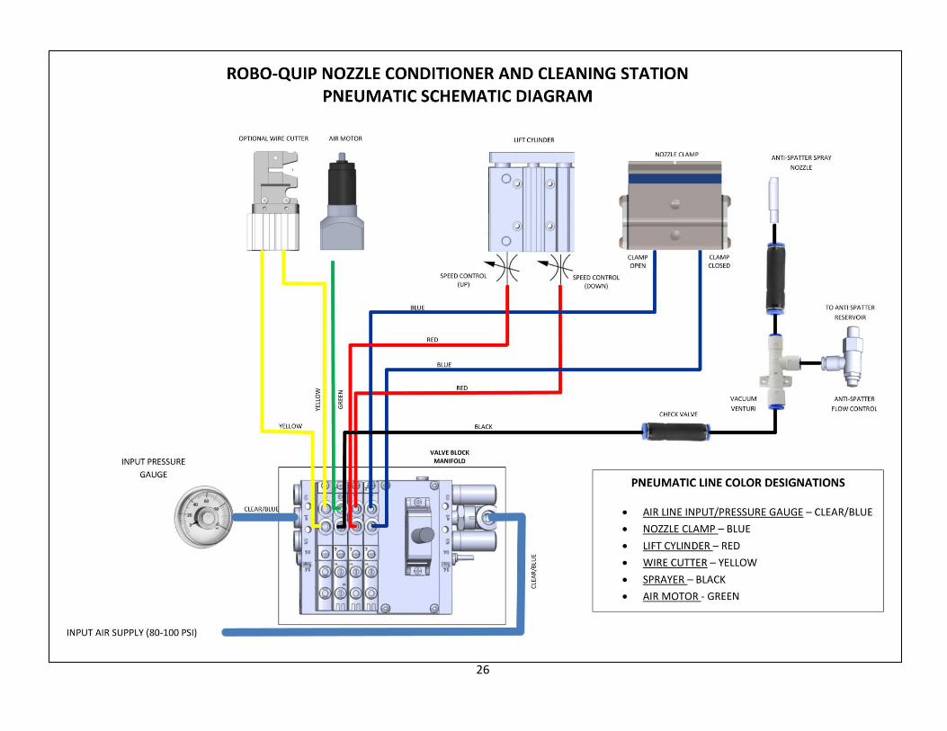
Air Supply
The Robo-Quip nozzle cleaning station requires 80-120 psi @ 8 S.C.F.M (5.0-7.0 BAR @ 450 LPM) of
clean shop air minimum for proper operation. The unit is equipped with a ¼” NPT female fitting for the
air supply connection. We recommend the “Quick Disconnect” style fittings for easy removal. It is
Important to use a supply line with at least 3/8” ID to insure proper air volume to the reamer. The
Robo-Quip
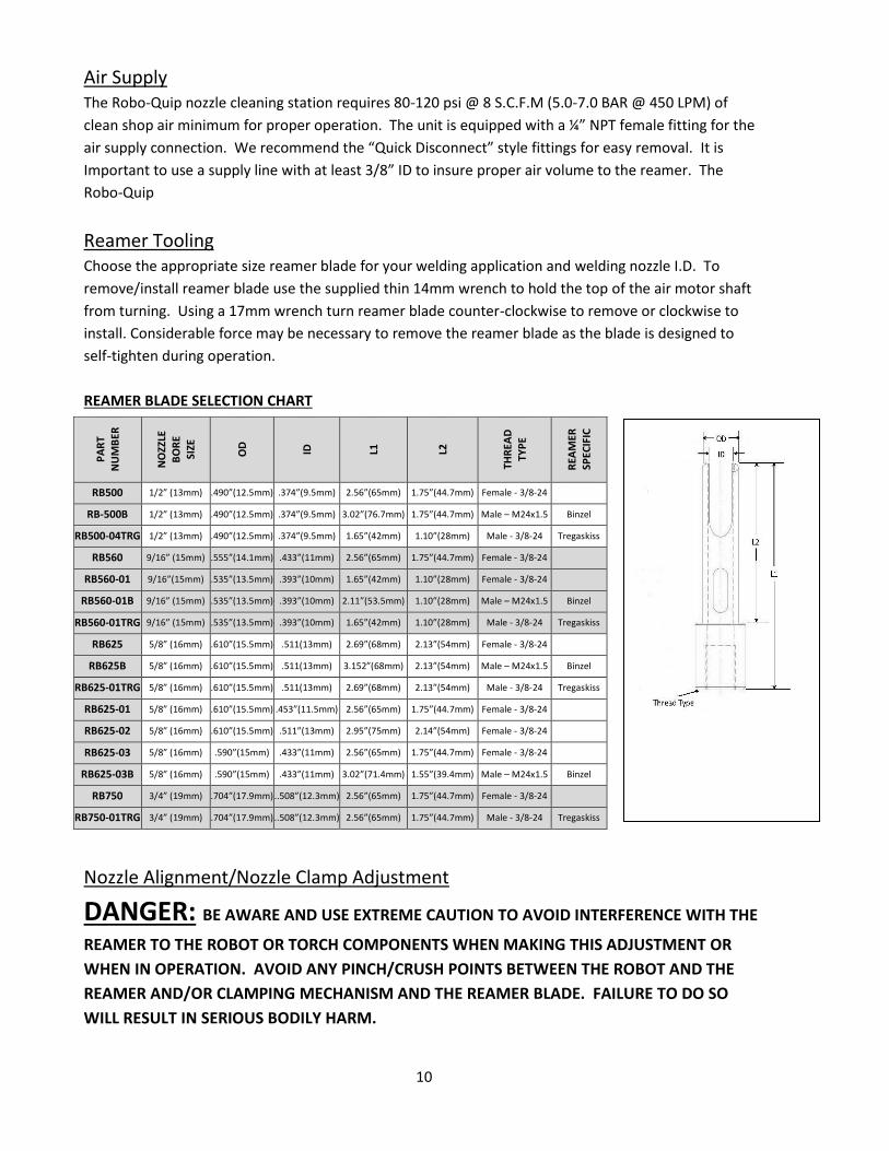
Reamer Tooling Choose the appropriate size reamer blade for your welding application and welding nozzle I.D. To
remove/install reamer blade use the supplied thin 14mm wrench to hold the top of the air motor shaft
from turning. Using a 17mm wrench turn reamer blade counter-clockwise to remove or clockwise to
install. Considerable force may be necessary to remove the reamer blade as the blade is designed to
self-tighten during operation.
REAMER BLADE SELECTION CHART
Nozzle Alignment/Nozzle Clamp Adjustment
DANGER: BE AWARE AND USE EXTREME CAUTION TO AVOID INTERFERENCE WITH THE
REAMER TO THE ROBOT OR TORCH COMPONENTS WHEN MAKING THIS ADJUSTMENT OR
WHEN IN OPERATION. AVOID ANY PINCH/CRUSH POINTS BETWEEN THE ROBOT AND THE
REAMER AND/OR CLAMPING MECHANISM AND THE REAMER BLADE. FAILURE TO DO SO
WILL RESULT IN SERIOUS BODILY HARM.
11
The nozzle clamping system is self-adjusting and is designed to center and align any outside diameter
nozzle in relation to the reaming blade. This feature eliminates the need to change v-blocks or make any
adjustment to center the nozzle. The only adjustment required is to make sure the robot/nozzle is
straight in the reaming blade and to set the required inserting depth.
NOTE: While the nozzle clamping system will help to center the nozzle in relation to the cutter blade it
is important that the straight alignment of the welding nozzle and insertion depth is critical to the
proper operation of the Robo-Quip.
CAUTION: KEEP HANDS CLEAR OF NOZZLE CLAMP AND REAMER MOTOR/BLADE AS THIS IS A PINCH
POINT AND WILL CAUSE INJURY.
1) Setup – Activate the lift cylinder cycle so that the air motor is positioned in the “FULL” up position.
The air motor will NOT rotate and the nozzle clamp should remain open.
2) Determine Insertion Depth – Insertion depth of the nozzle in relation to the reamer blade is
controlled by robot placement. Depth adjustment should be made by the robot torch
operator/programmer. It may be possible on 5/8 bore nozzles and larger to reamer past the gas
holes on the diffuser. This will depend on the ID of the reamer blade, OD of the diffuser and length
of the reamer blade. Normally it is recommended to only ream the nozzle the length of the contact
tip. Use caution when trying to ream past the length of the contact tip on smaller bore nozzles.
3) Nozzle to Reaming Blade Alignment – It is critic that the nozzle is straight and perpendicular to the
reaming blade.
a) Position the nozzle over the reaming blade, making sure it is straight front and back and side to
side.
b) SLOWLY bring the robot/nozzle down over the reaming blade to the proper predetermined
insertion depth.
c) Activate the “CLAMP CLOSED” signal. Visually make sure that the nozzle is straight and jaws are
in full contact with the outside of the nozzle.
d) Release the “CLAMP CLOSED” Signal. The jaws should open.
e) Deactivate the lift cylinder and the air motor should fully retract.
f) Setup is complete.
4) For adjustment procedures of the feed rate for advancement and retraction of the reaming blade
see Page 15.
Anti-Spatter Anti-Spatter solution is added to the unit by removing the fill cap on top of the bottle. The bottle
capacity is approximately one and one-half (1.5) quarts. Adjustment of the application of anti-spatter
liquid is controlled by (1) spray time entered in the robot controller and (2) adjustment of the fluid
dispensed by means of the flow control valve mounted on the bottom of the anti-spatter bottle.
Application of too much anti-spatter liquid is just as bad as not enough. If set correctly all that is
required is a .2 to .5 second timed spray.

12
The help contain any over spray of anti-spatter liquid and to provide for a cleaner area the Robo-Quip is
supplied with an enclosed spray chamber. There is a bottle incorporated into the chamber to collect any
excess fluid. When the bottle becomes full just un-screw from the bottom of the unit and empty.
It is advised not to reuse this excess fluid as it has been contaminated and can contain particles that
may clog the spray system.
We recommend American Weldquip’s QUIP-MIST specially formulated Nozzle Conditioner and Anti-
Spatter for optimal performance.
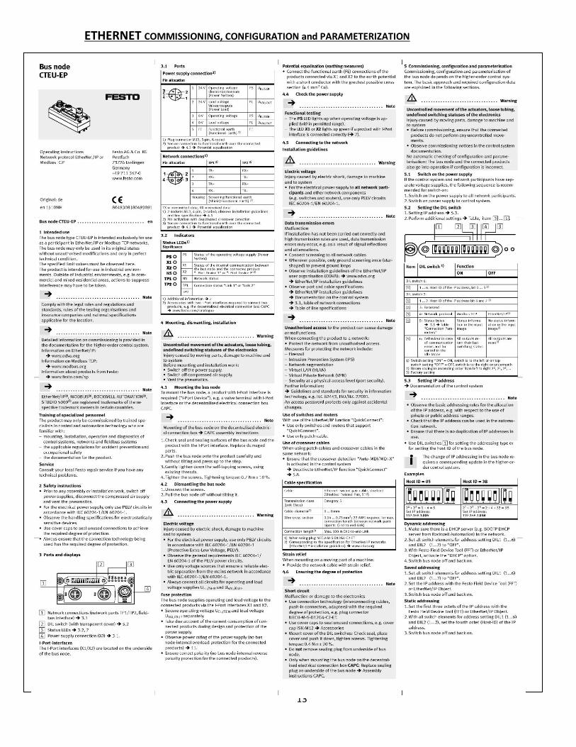
COMMISSIONING, CONFIGURATION and PARAMETERIZATION All the Ethernet/ProfNet connections and functions are sent directly to the FESTO valve manifold
assembly. The valve assembly controls the functions of the nozzle clamp, air motor rotation, lift
cylinder, anti-spatter sprayer and optional wire cutter. A “CYCLE COMPLETE” led light on the top of the
unit provides a visual indication that the lift cylinder/air motor is in the full down position and that the
nozzle clamps are fully open. A +24 VDC output signal is supplied through the 8 pin connector for input
to the robot controller that the reaming cycle is complete.
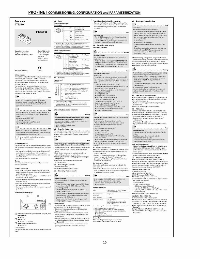
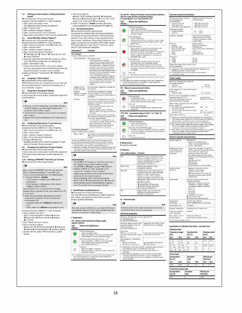
Commissioning, configuration and parameterization of the CTEU-EP and CTEU-NP bus node depends on
the higher-order control system. The basic approach and required configuration are explained on Pages
13& 14 Section 5.
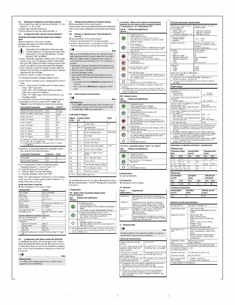
It is recommended to use the Festo Field Device Tool to commission the CTUE-EP Node. The Field
Device Tool is a “Wizard” that will lead you step by step on the commissioning. The Bus Node CTEU-EP
module must be configured for the desired IP address. See pages 13 thru 16 Section 5 for the steps
required for setting the IP address.
FFT – Festo Field Device Tool Device Tool for service and commissioning. The Festo Field Device Tool includes various services for all
Ethernet-based Festo field devices. It supports, among other features, the update of firmware files to
selected devices from Festo. To access the Field Device Tool go to
http://www.weldquip.com/literaturepage.html#TECHNICAL or visit FESTO at
https://www.festo.com/net/en-us_us/SupportPortal/default.aspx?q=2798071&tab=4&s=t#result.
Ethernet/IP EDS To access the EDS file go to http://www.weldquip.com/literaturepage.html#TECHNICAL or visit FESTO at
https://www.festo.com/net/en-us_us/SupportPortal/default.aspx?q=2798071&tab=4&s=t#result.
13
ETHERNET COMMISSIONING, CONFIGURATION and PARAMETERIZATION
14
15
PROFINET COMMISSIONING, CONFIGURATION and PARAMETERIZATION
16
17
OPERATION
Robot Programming/Reamer Sequence of Operation
The cycle time for nozzle cleaning is controlled by the robot program.
1) If using the wire cutter place the robotic torch in position over the cutter. Activate the “Wire Cutter” Solenoid
for .25 seconds.
2) Place the robotic torch in position between the nozzle clamps. Activate the “Nozzle Clamp” Solenoid to close
the clamps..
3) Activate the “Air Motor” Solenoid to start the air motor rotation.
4) Activate the “Lift Cylinder” Solenoid to advance the lift cylinder upwards. Keep the lift cylinder active until the
desired cleaning time has been completed.
5) Once the “Lift Cylinder” has been de-activated keep the air motor rotation activated until it has reached the
bottom of the stroke. De-activate the “Air Motor” Solenoid.
6) Once the air motor has stopped rotation and is at the bottom of its stroke de-activate the “Nozzle Clamp”
Solenoid.
7) When the “Nozzle Clamp” is open and the “Lift Cylinder” is in the full down position the “Cycle Complete” light
on the top of the Robo-Quip will lite indicating that that it is ok for the robot to move. There is also a +24vdc
signal available from the 8-pin 24 volt power cable to indicate the cycle is completed.
Robot Programming/Spray Function The cycle time for the Spray function is controlled by the robot program.
1) Move the robot torch in position to the sprayer.
2) Activate the “Sprayer” Solenoid for the desired spray time and then de-activate.
Usual recommended spray time is .2 seconds to .5 seconds depending on the anti-spatter compound. Avoid over
saturating the nozzle. Application of too much anti-spatter liquid is just as bad as not enough. If set correctly all
that is required is a maximum of .5 second timed spray.
Feed Rate Adjustment The feed rate “UP” and/or “DOWN can be controlled by adjusting the flow control valves located on the lift
cylinder inside the unit. Remove the rear cover for access to the valves. The top valve controls the speed in the
“DOWN” direction. The bottom valve controls the speed in the “UP” direction.
THEORY OF OPERATION 1) CYCLE COMPLETE SIGNAL - When +24 volt power is supplied to the Robo-Quip nozzle cleaning station and
the lift cylinder is fully in its down position and the clamping jaws are fully open, the clamp cylinder
normally open reed switch(RQ-0506) and the Lift Cylinder normally open reed switch (on the left side of
the lift cylinder) (RQ-0562) close. +24 volts is then supplied through the reed switches completing the
circuit to the green LED light (RQ-0563) on the top of the Robo-Quip and output of +24 volts is provided
back to the robot controller. This signal tells the robot controller that the lift cylinder is fully down and
the clamps are completely open and it is ok for the torch to move. These two reed switches are wired in
18
series with each other so if one is defective or if the clamp is not fully open or lift cylinder is not fully
down no +24 volts will be sent back to the controller and the LED on top of the Robo-Quip will not light.
2) CYCLE START SIGNAL – This is a timed output that determines the length of the reaming cycle. In SINKING
Logic when the robot controller supplies a timed output of 0 volts (GROUND) to the Robo-Quip
nozzle cleaning station the cleaning cycle will begin. The Nozzle Clamp valve on the manifold
will activate supplying air pressure to the clamp cylinder. The clamp (nozzle jaws) cylinder will
close, opening the reed switch and dropping the +24 volt CYCLE COMPLETE signal back to the
controller. Simultaneously, the lift cylinder valve on the manifold will activate supplying air
pressure to the lift cylinder. The lift cylinder will begin its upward movement opening the left
side reed switch used for the CYCLE COMPLETE signal. At the same time, the right-side reed
switch (Normally Closed) will close activating the air motor valve on the manifold and the air
motor will begin to rotate.
After the timed 0volt (GROUND) has been removed the lift cylinder and clamp cylinder valves on the
manifold are deactivated. This will cause the lift cylinder to move down and the jaws to open. Once these
are in their fully open and down position the lift cylinder reed switch and the lift cylinder left side reed
switch will close and the +24 volt “CYCLE COMPLETE” signal will be set to the robot controller and the LED
on the top of the Robo-Quip will light. At the same time, once the lift cylinder is at its full downward
stroke the air motor reed switch on the right side will open and the air motor valve on the manifold will
deactivate and the air motor will cease to rotate.
3) SPRAYER OPERATION - This is a timed output that determines the length of the spray cycle. In SINKING
Logic when the robot controller supplies a timed output of 0 volts(GROUND) for spraying to the
Robo-Quip the anti-spatter spray cycle will begin. The Sprayer valve on the manifold will
activate supplying air pressure through a Venturi valve, which will draw anti-spatter compound
from the storage tank, and proceed onto the enclosed sprayer housing and through the spray
tip. Once the 0 volt(GROUND) is removed or timed out the sprayer valve on the manifold is
deactivated and the sprayer function will cease operation.
4) WIRE CUTTER OPERATION - This is a timed output that determines the length of the wire cutting cycle. In
SINKING Logic when the robot controller supplies a timed output of 0 volts(GROUND) for wire
cutting to the Robo-Quip the wire cutting cycle will begin. The Wire Cutting valve on the
manifold will activate supplying air pressure to the wire cutter air cylinder which will close the
cutting blades. Once the 0 volt(GROUND) is removed or timed out the wire cutter valve on the
manifold is deactivated and the wire cutting blade will open .
TROUBLESHOOTING
1) LED LIGHT NOT LITE AND/OR NO +24 VOLT CYCLE COMPLETE SIGNAL BACK TO ROBOT CONTROLLER
a. Loss of power to the reamer. Make sure there is + 24 volts to the Robo-Quip.
b. Defective Clamp Cylinder and/or Lift Cylinder reed switch.
c. Defective LED CYCLE COMPLETE light. – Replace the LED
2) AIR MOTOR ROTATES CONTINUOUSLY
a. Defective reed switch – This reed switch is on the right side of the lift cylinder. Remove one
lead from the terminal strip (#7 or #10) and check for continuity. With the lift cylinder full
downward reed switch should be OPEN. When lift cylinder is moved upward the reed switch
19
should close. If the reed switch does not close when the lift cylinder is moved upward
replace the defective reed switch. See Maintenance Section for reed switch replacement
instructions.
b. If the air motor slowly rotates when only incoming air is supplied to the Robo-Quip but not
activated.
i. Remove the valve from the manifold and check the condition of the rubber seals.
ii. Defective valve – replace.
3) AIR MOTOR ROTATES SLOWLY OR NOT AT ALL
a. Check incoming air supply pressure. Check air gauge on the side of the Robo-Quip for the
minimum 80 psi input air pressure.
b. Check the Air Motor valve on the valve manifold for signal. When “CYCLE START’ signal is
sent to the ROBO-QUIP and the lift cylinder move upward check the valve LED light on the
valve manifold to make sure it is lite. If not,
i. Check wiring as it is not getting a signal
ii. Replace defective valve
c. Defective Air Motor – Replace
d. Defective reed switch – This reed switch is on the right side of the lift cylinder. Remove one
lead from the terminal strip and check for continuity. With the lift cylinder full downward
reed switch should be OPEN. When lift cylinder is moved upward the reed switch should
close. If the reed switch does not close when the lift cylinder is moved upward replace the
defective reed switch. See Maintenance Section for reed switch replacement instructions.
e. If the air motor slowly rotates when only incoming air is supplied to the Robo-Quip but not
activated.
i. Remove the valve from the manifold and check the condition of the rubber seals.
ii. Defective valve – replace.
4) LIFT CYLINDER WILL NOT OPERATE OR IS SLUGGISH
a. Check incoming air supply pressure. Check air gauge on the side of the Robo-Quip for the
minimum 80 psi input air pressure.
b. Check the Lift Cylinder valve on the valve manifold for signal. When “CYCLE START’ signal is
sent to the ROBO-QUIP the lift cylinder valve LED light on the valve manifold should lite. If
not,
i. Check wiring – It is not getting a signal.
c. Check the two (2) speed adjustment valve on the cylinder for proper adjustment and make
sure they are not plugged. Replace the speed adjustment valves if defective.
d. Defective Valve - Replace defective valve
e. Defective Lift Cylinder - Replace the lift cylinder
5) REAMING BLADE STICKS IN NOZZLE OR MISALIGNED
a. Check incoming air supply pressure. Check air gauge on the side of the Robo-Quip for the
minimum 80 psi input air pressure.
b. Dull or broken reaming cutting blade. Replace Reaming Blade.
c. Excessive spatter build-up in nozzle. Increase the frequency of torch cleaning.
d. Torch positioned incorrectly over reaming blade. Realign torch and nozzle so the blade
enters straight into the nozzle.
e. Torch clamping cylinder/jaws misaligned. Perform realignment of torch jaws. See
Maintenance section on page #16.
6) SPRAYER WILL NOT OPERATE
a. Check incoming air supply pressure. Check air gauge on the side of the Robo-Quip for the
minimum 80 psi input air pressure.
20
b. Check the Sprayer valve on the valve manifold for signal. When “SPRAYER” signal is sent to
the ROBO-QUIP the Sprayer valve LED light on the valve manifold should lite. Either activate
by means of the robot or press the sprayer test button on the side of the Robo-Quip. If not
lite,
i. Check wiring – It is not getting the on signal
ii. Defective Valve - Replace defective valve
c. Check for plugged check valves. There are two (2) – replace if plugged.
d. Check for plugged venturi valve – replace if plugged.
e. Check for plugged spray tip. Clean or replace
f. Check flow adjustment valve on spray reservoir tank. Make sure it is open. Replace tank if
plugged.
7) SPRAYER ANTI-SPATTER FLUID LEAKING INTO VALVE ASSEMBLY
a. Replace the check valve between the Sprayer valve on the valve manifold and the venturi.
8) SPRAYER ANTI-SPATTER FLUID LEAKING INTO SPRAY ENCLOSURE AND SPRAY TIP
a. Replace the check valve between venturi and the spray enclosure
9) SPRAYER ANTI-SPATTER FLUID SPRAYS WHEN AIR CONNECTION TO REAMER IS CONNECTED
i. Remove the sprayer valve from the manifold and check the condition of the rubber
seals.
ii. Defective valve – replace.
10) SPRAYER BLOW BY AIR ENTERING INTO ANTI-SPATTER RESERVOIR TANK
a. Plugged orifice on spray tip or too small of orifice used.
b. Plugged Check valve or air lines.
11) NOT ENOUGH ANTI-SPATTER SPRAY
a. Check that the Flow Control adjustment valve on the Reservoir tank is open.
b. Plugged orifice on spray tip or too small of orifice used.
c. Plugged check valve or air lines.
d. Plugged or defective venturi valve.
e. Defective flow valve on reservoir tank.
12) WIRE CUTTER WILL NOT OPERATE OR IS SLUGGISH
a. Check incoming air supply pressure. Check air gauge on the side of the Robo-Quip for the
minimum 80 psi input air pressure.
b. Check the Wire Cutter valve on the valve manifold for signal. When “WIRE CUTTER signal is
sent to the ROBO-QUIP the wire cutter valve LED light on the valve manifold should lite. If
not,
i. Check wiring – It is not getting the on signal
ii. Defective Valve - Replace defective valve
c. Defective wire cutter air cylinder - Replace
13) WIRE CUTTER WILL NOT CUT THROUGH WIRE
a. Check incoming air supply pressure. Check air gauge on the side of the Robo-Quip for the
minimum 80 psi input air pressure.
b. Check wire size used to be cut. 1/16” is largest recommended size in most applications.
c. Dull or defective cutting blade – Replace cutting blade.
21
MAINTENANCE
1) RE-ALIGN CLAMP CYLINDER/JAWS TO REAMING CUTTER BLADE
1) Make sure there is +24 volts electrical power to the Robo-Quip
2) Loosen the four (4) screws on the top of the reamer. DO NOT REMOVE. Once lose you should
be able to wiggle the jaw set around slightly.
3) Place the RUN/SETUP switch in “Setup” mode. This is a locking type switch so you
need to pull the switch out before moving to the “Setup” mode. CAUTION: MAKE SURE
YOU HANDS ETC ARE CLEAR OF THE FRONT OF THE REAMER. AS SOON AS THE SWITCH IS
MOVED TO THE “SETUP” MODE THE LIFT CYLINDER WILL ADVANCE UPWARD.
4) Using either a spare gooseneck with the consumables on it or moving the Robot into
position place the nozzle to the correct depth over the reaming blade making sure it is
straight on the reaming blade.
5) On the side of the reamer press the "CYCLE" button. CAUTION: MAKE SURE YOUR HANDS
ETC. ARE CLEAR OF THE FRONT AND TOP OF THE REAMER. AS SOON AS THE “CYCLE
BUTTON IS PRESSED THE JAWS WILL CLOSE CAUSING A PINCH POINT.
This will close the jaws. NOTE: You need to hold the “CYCLE” button in while adjusting and
tightening the screws otherwise the jaws will open.
6) While the jaws are closed give the jaw/clamp assembly a slight wiggle.
7) While continuing to press the “CYCLE” button tighten the four (4) screw on the top of the
reamer.
8) Release the “CYCLE’ Button. The jaws will now open
9) Move the SETUP/RUN switch to the "RUN" position. The reamer motor will advance down,
and the air motor will begin to rotate (Rotation will cease after the lift cylinder is in its fully
downward position.
10) To test the alignment, leave the torch in position and press the "CYCLE" button.
2) REED SWITCH REPLACEMENT
The Robo-Quip incorporates three (3) reed switches.
• JAW CLAMP CYLINDER REED SWITCH – Normally Open. When the jaws are in the fully open
position the reed switch is closed and completes the circuit to provided power through the LED
light on the top of the Robo-Quip and +24 volts Cycle Complete signal back to the robot
controller. NOTE: This reed switch and one on the lift cylinder are wired in series. If one or the
other is defective the LED light will not light and no +24-volt signal will be sent to the robot
controller.
• LIFT CYLINDER REED SWITCHES – The lift cylinder incorporates two (2) reed switches.
a. The reed switch on the left side of the lift cylinder is a Normally Open switch. In
conjunction with the reed switch (wired in series) on the clamp cylinder, if this reed switch is
defective the LED light will not light and no +24-volt signal will sent to the robot controller.
b. The reed switch on the right side of the lift cylinder is a Normally Closed switch. When
the “cycle start” is activated and the lift cylinder begins its upward movement this switch will
close competing the circuit and closing the air motor valve causing the air motor to begin its
rotation. Air motor rotation will not cease until the lift cylinder is almost to its full downward
stroke.
JAW/CLAMP CYLINDER REED SWITCH REPLACEMENT
You will need to remove the jaw/clamp cylinder from the Robo-Quip to access the reed switch.
1) Disconnect the two pneumatic air lines.
22
2) Disconnect the one side of the reed switch from the terminal strip. This is the BLUE lead
located on terminal #1.
3) The other wire end of the reed switch is BLUE and is a crimped connection that is connected
in series with the reed switch (black lead) from the lift cylinder. Cut off the crimp connection.
4) Remove the four (4) screws from the top on the Robo-Quip and remove the complete clamp
assembly.
5) The reed switches are slid into a track on the air cylinder. They are held in place by a
standard silicone RTV sealant. Using a Sharp knife or razor blade slice along both top sides of
the reed switch to cut the existing TRV sealant.
6) Using a small blade screwdriver or similar use a hammer and tap out the defective reed
switch.
7) Clean the slot on the air cylinder of any remaining RTV sealant.
8) NOTE: PLACEMENT OF THE REED SWITCH IS IMPORTANT FOR PROPER OPERATION. On the
side of the slot place a pencil mark approximately 3/16”(4.5mm) from the end of the clamp
cylinder.
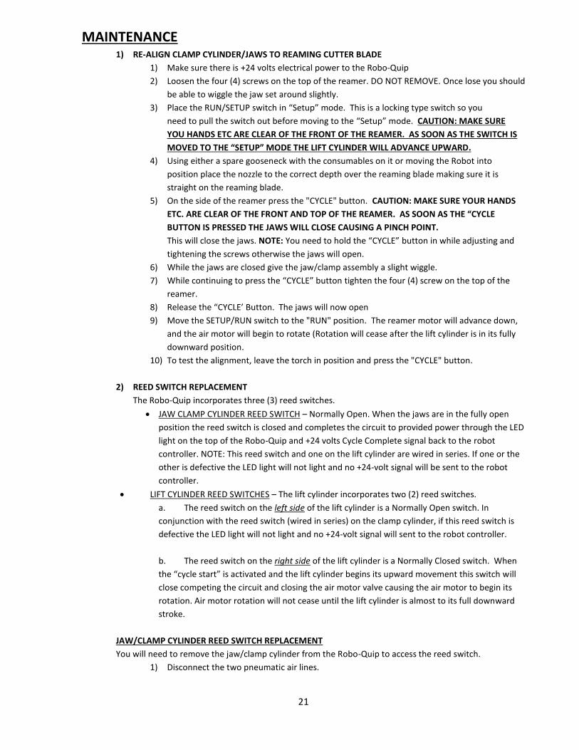
9) Put good amount of RTV sealant in the groove
where the new reed switch will be placed.
10) Slide the new reed switch in place so the end of
the reed switch with the wire leads is
3/16”(4.5MM) in from the end of the cylinder.
11) Let dry.
12) Reinstall the Jaw/Clamp cylinder back into the
Robo-Quip.
13) Reinstall the wiring. It does not matter which
lead goes where. You will need to re-crimp one
of the leads to the reed switch from the lift cylinder.
14) Reconnect the pneumatic air lines.
LIFT CYLINDER REED SWITCH REPLACEMENT
Even though it may be a little tight you do not need remove the lift cylinder from the Robo-Quip to access
the reed switches.
1) Disconnect the two pneumatic air lines. You may want to remove the other pneumatic air
lines in the Robo-Quip to gain better access.
2) Depending on the reed switch to be remove disconnect the one side of the reed switch from
the terminal strip.
a. The reed switch on the left side – CYCLE COMPLETE – One side goes to the
crimp connection that is connected in series with the reed switch (blue lead) on
the clamp cylinder. Remove this crimp and remove the other side of the reed
switch from terminal #6 on the terminal strip.
b. The reed switch on the right side – AIR MOTOR ROTATION – Disconnect each
lead from the terminal strip positions #7 and 10.
3) The reed switches are slid into a track on the lift cylinder. They are held in place by a
standard silicone RTV sealant. Using a Sharp knife or razor blade slice along both top sides of
the reed switch to cut the existing TRV sealant.
4) Using a small blade screwdriver or similar use a hammer and tap out the defective reed
switch.
5) Clean the slot on the lift cylinder of any remaining RTV sealant.
23
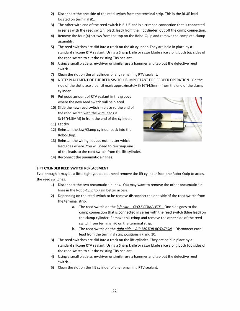
6) NOTE: PLACEMENT OF THE REED SWITCH IS IMPORTANT FOR PROPER OPERATION. On the
side of the slot place a pencil mark approximately 3/16”(4.5mm) from the end of the lift
cylinder.
7) Put a good amount of RTV sealant in the
groove where the new reed switch will be
placed.
8) Slide the new reed switch in place so the end
of the reed switch without the wire leads is
3/16”(4.5MM) in from the end of the cylinder.
9) Let dry.
10) Reinstall the wiring. It does not matter which
lead goes where. In the case of the “Cycle
Complete” reed switch you will need to re-
crimp one of the leads to the reed switch from the lift cylinder.
11) Reconnect all the pneumatic air lines.
3) WIRE CUTTER BLADE REPLACEMENT
The wire cutter replacement blade kit consists of four (4) components.
1) Cutter Blade
2) Cutter Block
3) Cutter Stop Block
4) Spring
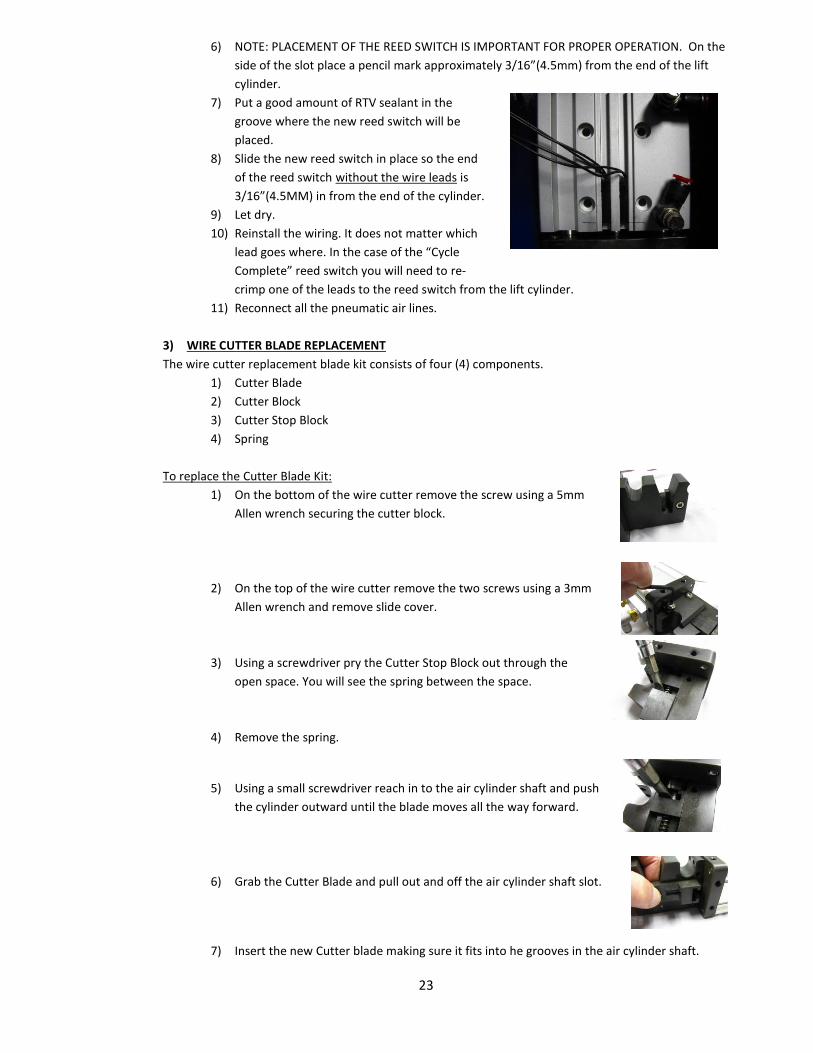
To replace the Cutter Blade Kit:
1) On the bottom of the wire cutter remove the screw using a 5mm
Allen wrench securing the cutter block.
2) On the top of the wire cutter remove the two screws using a 3mm
Allen wrench and remove slide cover.
3) Using a screwdriver pry the Cutter Stop Block out through the
open space. You will see the spring between the space.
4) Remove the spring.
5) Using a small screwdriver reach in to the air cylinder shaft and push
the cylinder outward until the blade moves all the way forward.
6) Grab the Cutter Blade and pull out and off the air cylinder shaft slot.
7) Insert the new Cutter blade making sure it fits into he grooves in the air cylinder shaft.
24
8) Insert the new spring making sure it is compressed and properly in its holding slot in the
cutter blade.
9) Place the cutter stop block all the way forward, and while keeping a downward pressure
push the block back towards the air cylinder. You will notice a slot where the spring will ride
and a hole where the dowel pin in the cutter blade will mate. You will feel the pin lock mate
with the cutter block.
10) Reattach the slide cover removed in 2) above with the two screws using a 3mm Allen
wrench.
11) Reinstall the cutter block and secure with the screw using a 5mm Allen wrench.
WIRE CUTTER INSTALLATION (RQ-1000 WIRE CUTTER KIT) The RQ-1000 Wire Cutter Kit includes.
1ea. RQ-0552 Wire Cutter and Slide Shute
2ea. RQ-0554 Spacer Washer
2ea. RQ-0558 Push To Connect Fitting
18” RQ-0513Y Pneumatic Hose
1ea. RQ-0524 Single Stage Valve
1) Remove the rear cover of the Robo-Quip.
2) Remove the two (2) hole plugs on the right side of the Robo-Quip where the wire cutter will be
mounted.
3) Place the spacer washer(s) on the threaded ends of the push to connect fittings. The push to connect
fittings are used to secure the wire cutter to the reamer box.
4) Hold the wire cutter in position. Line up the two air input holes on the wire cutter air solenoid to the
two holes in the side of the Robo-Quip.
5) Thread the two push to connect fittings with the spacer washers installed into the two threaded posts
on the wire cutter.
6) Tighten the two (2) push to connect fittings.
7) Using a PHILLIPS heads screwdriver loosen and remove the blank valve from the valve manifold. This
will be the fourth position from the right.
8) Install the RQ-0524 single stage valve.
9) Cut the 18” length of pneumatic hose in two equal lengths.
10) Push on end of both hoses securely into the push to connect fittings on the wire cutter air cylinder.
11) Push the other ends of both hoses in the single stage valve on the valve manifold. IMPORANT: The air
line connection on the wire cutter that is towards the front of the reamer is connected to the front
most push to connect fitting on the single stage valve.
If reversed, when the Robo-Quip is connected to electric and air the wire cutter will close without be
activated. Reverse the air line connections.

16
26
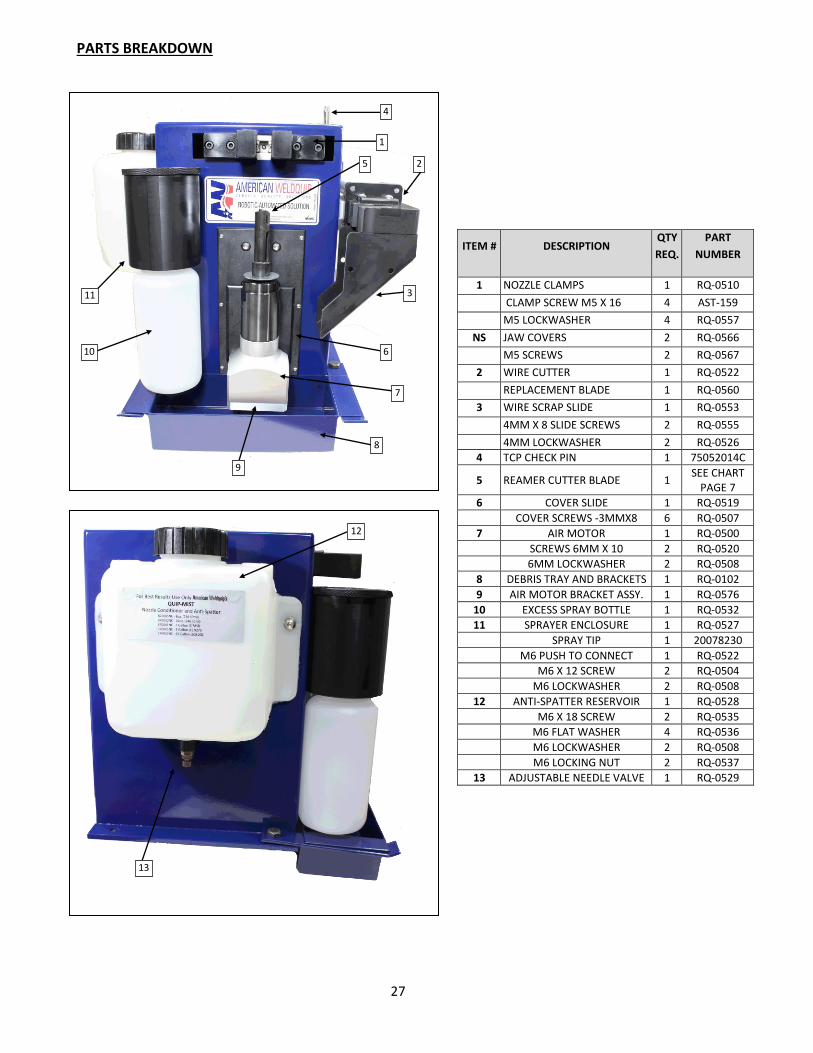
PARTS BREAKDOWN
3
2
1
6
7
11
8
10
4
9
12
13
ITEM # DESCRIPTION QTY
REQ.
PART
NUMBER
1 NOZZLE CLAMPS 1 RQ-0510
CLAMP SCREW M5 X 16 4 AST-159
M5 LOCKWASHER 4 RQ-0557
NS JAW COVERS 2 RQ-0566
M5 SCREWS 2 RQ-0567
2 WIRE CUTTER 1 RQ-0522
REPLACEMENT BLADE 1 RQ-0560
3 WIRE SCRAP SLIDE 1 RQ-0553
4MM X 8 SLIDE SCREWS 2 RQ-0555
4MM LOCKWASHER 2 RQ-0526
4 TCP CHECK PIN 1 75052014C
5 REAMER CUTTER BLADE 1 SEE CHART
PAGE 7
6 COVER SLIDE 1 RQ-0519
COVER SCREWS -3MMX8 6 RQ-0507
7 AIR MOTOR 1 RQ-0500
SCREWS 6MM X 10 2 RQ-0520
6MM LOCKWASHER 2 RQ-0508
8 DEBRIS TRAY AND BRACKETS 1 RQ-0102
9 AIR MOTOR BRACKET ASSY. 1 RQ-0576
10 EXCESS SPRAY BOTTLE 1 RQ-0532
11 SPRAYER ENCLOSURE 1 RQ-0527
SPRAY TIP 1 20078230
M6 PUSH TO CONNECT 1 RQ-0522
M6 X 12 SCREW 2 RQ-0504
M6 LOCKWASHER 2 RQ-0508
12 ANTI-SPATTER RESERVOIR 1 RQ-0528
M6 X 18 SCREW 2 RQ-0535
M6 FLAT WASHER 4 RQ-0536
M6 LOCKWASHER 2 RQ-0508
M6 LOCKING NUT 2 RQ-0537
13 ADJUSTABLE NEEDLE VALVE 1 RQ-0529
5
27
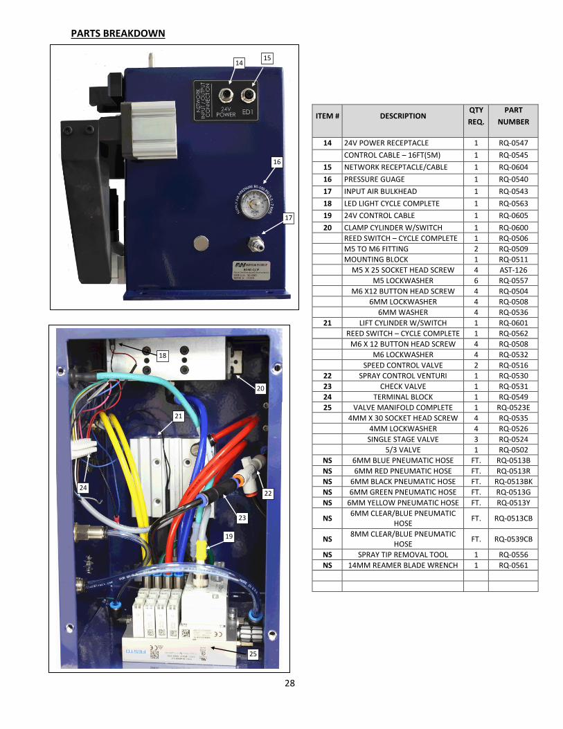
PARTS BREAKDOWN
ITEM # DESCRIPTION QTY
REQ.
PART
NUMBER
14 24V POWER RECEPTACLE 1 RQ-0547
CONTROL CABLE – 16FT(5M) 1 RQ-0545
15 NETWORK RECEPTACLE/CABLE 1 RQ-0604
16 PRESSURE GUAGE 1 RQ-0540
17 INPUT AIR BULKHEAD 1 RQ-0543
18 LED LIGHT CYCLE COMPLETE 1 RQ-0563
19 24V CONTROL CABLE 1 RQ-0605
20 CLAMP CYLINDER W/SWITCH 1 RQ-0600
REED SWITCH – CYCLE COMPLETE 1 RQ-0506
M5 TO M6 FITTING 2 RQ-0509
MOUNTING BLOCK 1 RQ-0511
M5 X 25 SOCKET HEAD SCREW 4 AST-126
M5 LOCKWASHER 6 RQ-0557
M6 X12 BUTTON HEAD SCREW 4 RQ-0504
6MM LOCKWASHER 4 RQ-0508
6MM WASHER 4 RQ-0536
21 LIFT CYLINDER W/SWITCH 1 RQ-0601
REED SWITCH – CYCLE COMPLETE 1 RQ-0562
M6 X 12 BUTTON HEAD SCREW 4 RQ-0508
M6 LOCKWASHER 4 RQ-0532
SPEED CONTROL VALVE 2 RQ-0516
22 SPRAY CONTROL VENTURI 1 RQ-0530
23 CHECK VALVE 1 RQ-0531
24 TERMINAL BLOCK 1 RQ-0549
25 VALVE MANIFOLD COMPLETE 1 RQ-0523E
4MM X 30 SOCKET HEAD SCREW 4 RQ-0535
4MM LOCKWASHER 4 RQ-0526
SINGLE STAGE VALVE 3 RQ-0524
5/3 VALVE 1 RQ-0502
NS 6MM BLUE PNEUMATIC HOSE FT. RQ-0513B
NS 6MM RED PNEUMATIC HOSE FT. RQ-0513R
NS 6MM BLACK PNEUMATIC HOSE FT. RQ-0513BK
NS 6MM GREEN PNEUMATIC HOSE FT. RQ-0513G
NS 6MM YELLOW PNEUMATIC HOSE FT. RQ-0513Y
NS 6MM CLEAR/BLUE PNEUMATIC
HOSE FT. RQ-0513CB
NS 8MM CLEAR/BLUE PNEUMATIC
HOSE FT. RQ-0539CB
NS SPRAY TIP REMOVAL TOOL 1 RQ-0556
NS 14MM REAMER BLADE WRENCH 1 RQ-0561
18
19
21
22 24
5
23
20
25
28
14 15
16
17

NOTES:

OM015 – 02/17
1375 Wolf Creek Trail – P.O. Box 397
Sharon Center, Ohio 44274
330-239-0317 Telephone / 800-949-9353 Fax