RPT ON ARMSTONG-COPPER PROS HALKIRK TP RAINY L AREA EM … · a shallow drill program in 1956 by...
62
CHESTER J. KURYL.IW. M.Sc.. P.ENG. 46 IMCAU, DR. DRYDEN, ONTARIO fm *BT S2C10NWD041 2 16122 HALKIRK 010 PHONE 807-223-6080 g. 16122 REPORT ON ARMSTRONG - COPPER PROSPECT HALKIRK TWP. RAINY LAKE AREA OF ONTARIO EM - 17 HORIZONTAL LOOP ELECTRO MAGNETIC GROUND SURVEY FEBRUARY 20, 1995 CHESTER J. KURYLIW
-
Upload
vuonghuong -
Category
Documents
-
view
213 -
download
0
Transcript of RPT ON ARMSTONG-COPPER PROS HALKIRK TP RAINY L AREA EM … · a shallow drill program in 1956 by...
CHESTER J. KURYL.IW. M.Sc.. P.ENG.
46 IMCAU, DR. DRYDEN, ONTARIO fm *BT
S2C10NWD041 2 16122 HALKIRK 010
PHONE 807-223-6080
g. 16122
REPORT
ON
ARMSTRONG - COPPER PROSPECT
HALKIRK TWP. RAINY LAKE AREA OF ONTARIO
EM - 17 HORIZONTAL LOOP
ELECTRO MAGNETIC
GROUND SURVEY
FEBRUARY 20, 1995 CHESTER J. KURYLIW
- 2 -52C10NWOO41 2.16122 HALKIRK 01OC
TABLE OF CONTENTS
Project Location
Location Maps
Access to Project Site
Regional Geology and Mineralization
Local Geology and Interpretations
Instrument. Unit and Method
Results of the Survey
Conelus ions
Recoinmendat ions
Cert ificate
Plan of Electromagnetic Survey Scale l" = 200
- 3 -
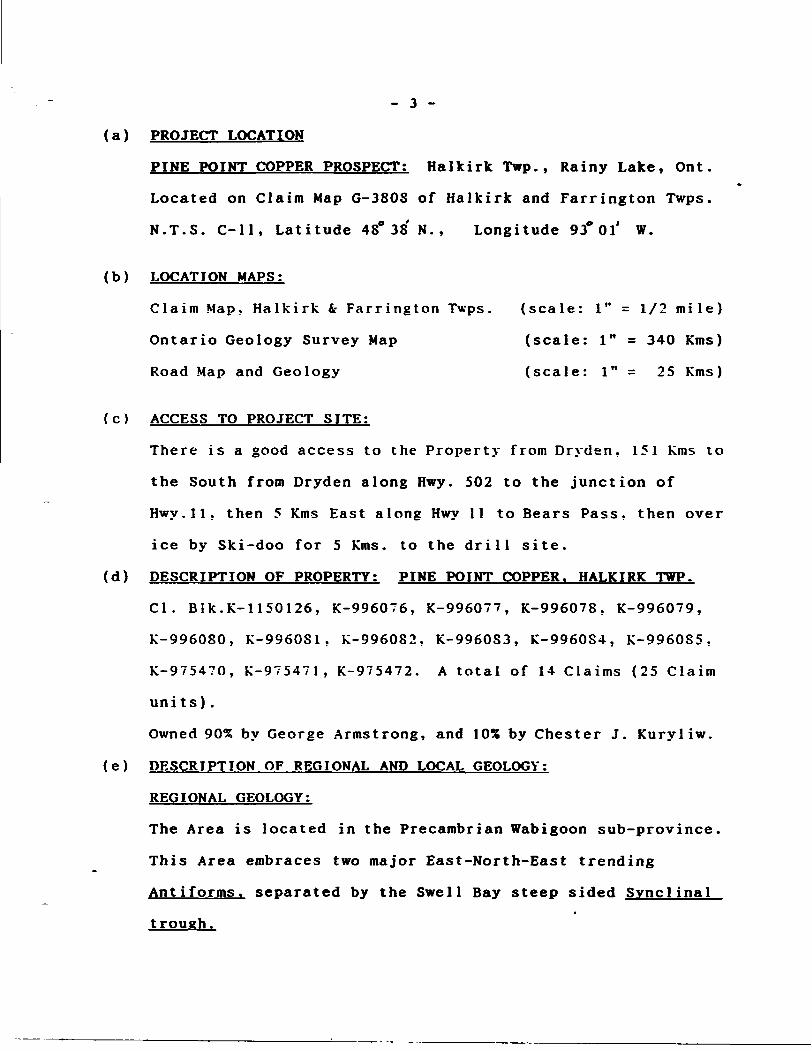
(a) PROJECT LOCATION
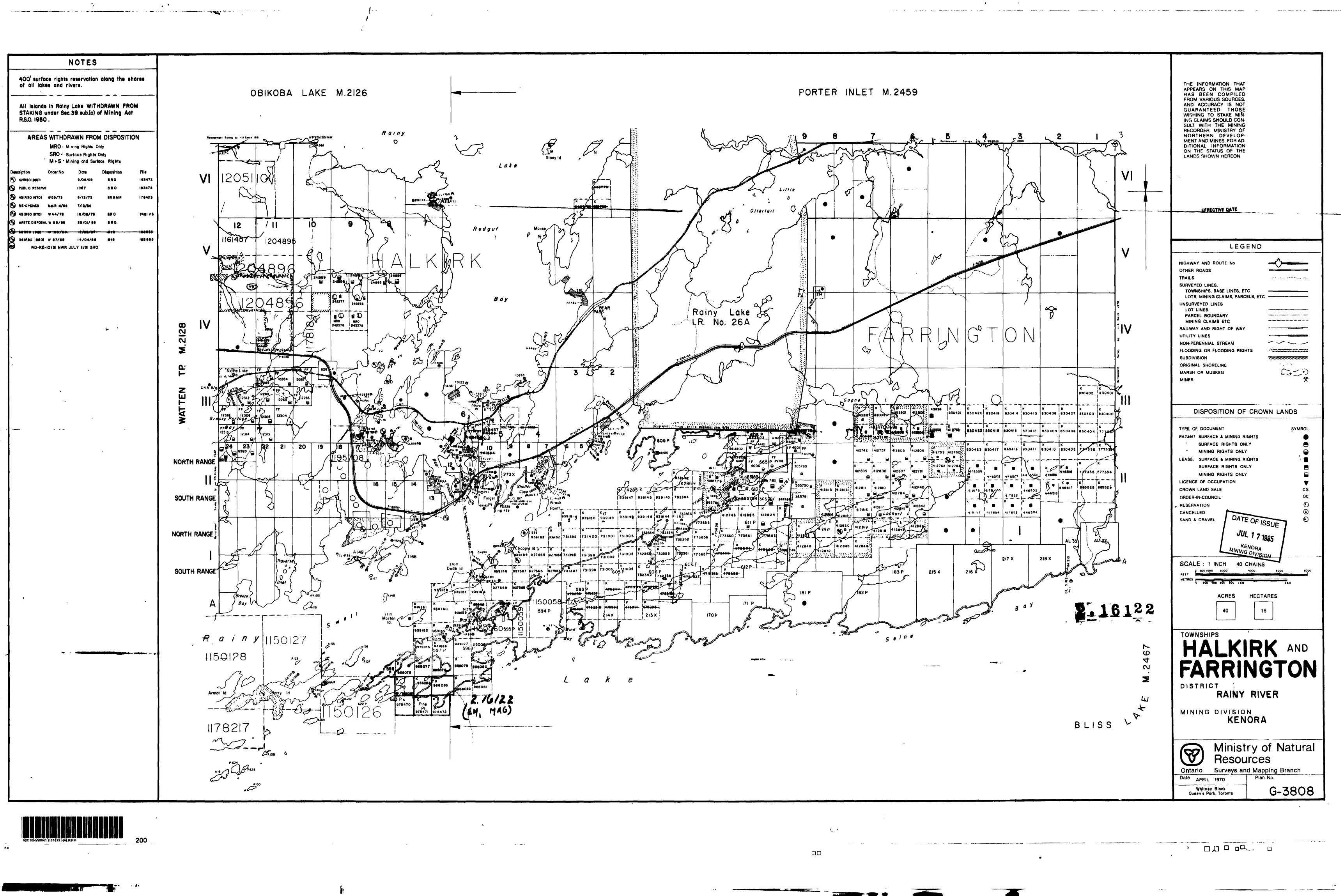
PINE POINT COPPER PROSPECT: Halkirk Twp., Rainy Lake, Ont.
Located on Claim Map G-3808 of Halkirk and Farrington Twps.
N.T.S. C-ll, Latitude 480 38N., Longitude 93*01* W.
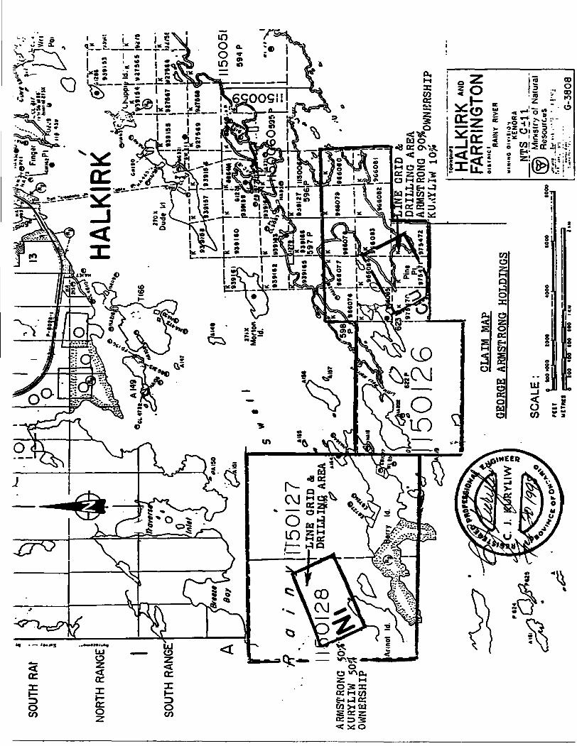
(b) LOCATION MAPS;
Claim Map, Halkirk fc Farrington Twps. (scale: l" = 1/2 mile)
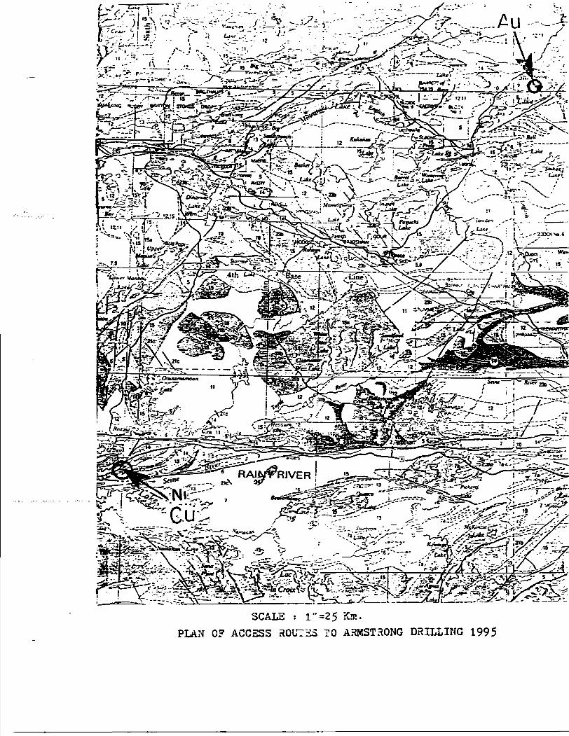
Ontario Geology Survey Map (scale: l" - 340 Kms)
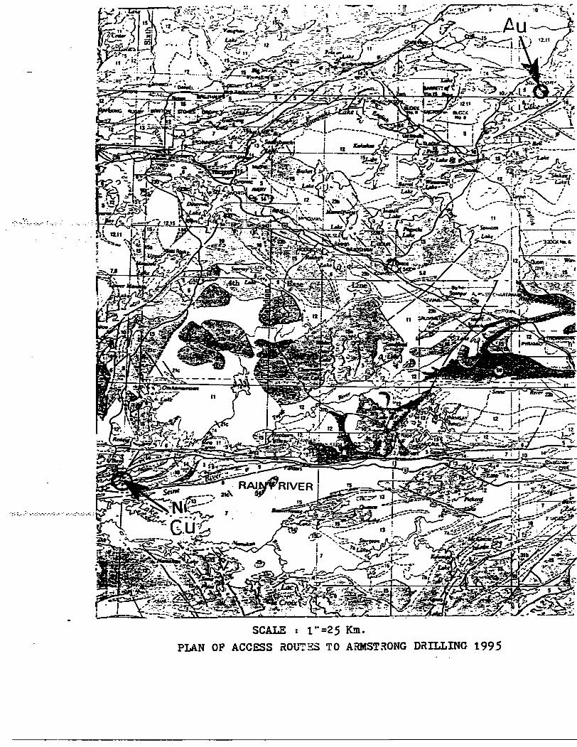
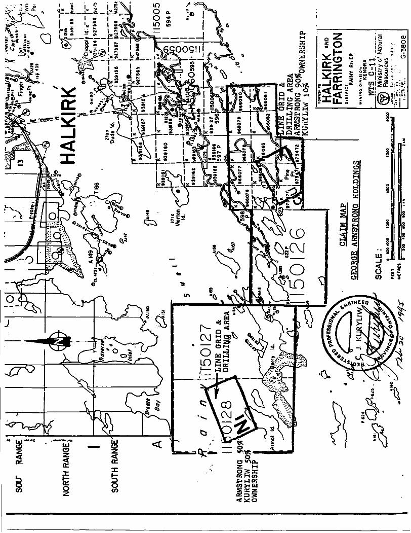
Road Map and Geology (scale: l" = 25 Kms)
(c) ACCESS TO PROJECT SITE:
There is a good access to the Property from Dryden. 151 Kms to
the South from Dryden along Hwy. 502 to the junction of
Hwy.ll, then 5 Kms East along Hwy 11 to Bears Pass, then over
ice by Ski-doo for 5 Kms. to the drill site.
(d) DESCRIPTION OF PROPERTY: PINE POINT COPPER. HALKIRK TWP.
CI. Blk.K-U50126, K-996076, K-996077, K-996078, K-996079,
K-996080, K-996081, K-996082, K-996083, K-996084, K-996085,
K-975470, K-975471, K-975472. A total of 14 Claims (25 Claim
units).
Owned 90% by George Armstrong, and 10/6 by Chester J. Kuryliw.
(e) DESCRIPTION OF REGIONAL AND LOCAL GEOLOGY;
REGIONAL GEOLOGY:
The Area is located in the Precambrian Wabigoon sub-province.
This Area embraces two major East-North-East trending
Ant i forms, separated by the Swell Bay steep sided Svnclinal
trough.
SOUT
H R
Af
i
NO
RTH
RAN
GE]
SOU
TH R
ANG
E"
ARM
STRO
NG
. KU
RYLI
W
50?
OWNE
RSHI
P
HA
LKIR
K
'——
(r- -
la—
—Js
"9)
9135
91
76*7
t*
279*
e l"
-*'
1 l
(/*
4
*^
i |_
_y
.i;—
— —
—|r
- JK
,..^
^ |^
11
50
05
1
99
4 P
F50I
27LI
NE
GRI
D A
D
RILL
iy,fi
ARE
A
DRI
LLIN
G A
REA
5012
6AR
MST
RONG
90#
HA
LKIR
K
FAR
RIN
GTO
NCL
AIM
MAP
GEORGE ARMSTRONG HOLDINGS
NT
S .O
il l.
.
Min
istry
of
Nat
ural
R
esou
rces
lw'
vi
. ' T
*.!
' l
l* I.
*
SC
AL
E:
9 lo
o lo
oo
too*
L-^.-Tx* i ,——f-^-H'-^'"^""'!-':: ~ i'-fc ".-v
tells^^Sp^^fife- O S j r* V u*g-^ 'l*, .-l-SS^e-tepy •-•,- 1,: t ^ 7 f* ^--~\?':,i
-
SCALE : l""25 Km. PLAN OP ACCESS ROUTES TO ARMSTRONG DRILLING 1995
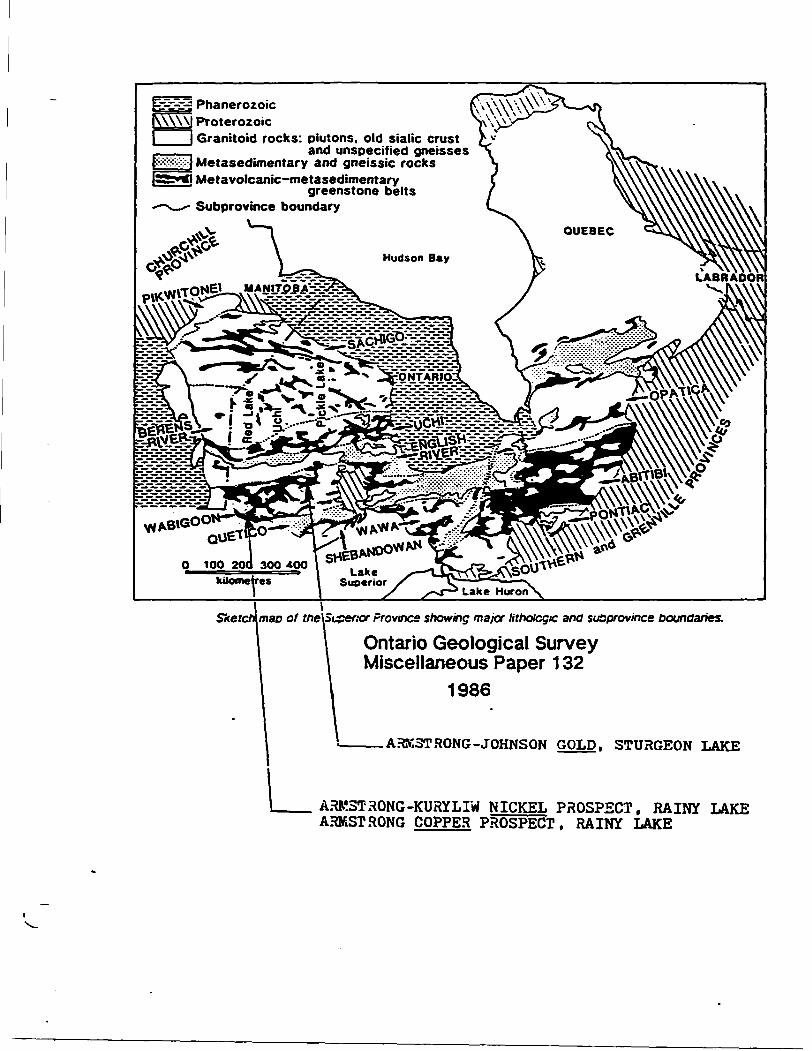
bc-I-S Phanerozoic ProterozoicGranitoid rocks: piutons. old sialic crust
and unspecified gneisses ___ Metasedimentary and gneissic rocks55j**i Metavolcanic-metasedimentary
greenstone belts' Subprovince boundary
*v
Sketch\maD of tne\Si^xf;or Province showing major lithologic ana suoprovincs boundaries.
Ontario Geological Survey Miscellaneous Paper 132
1986
——— A3N3T SONG -JOHNSON GOLD. STURGEON LAKE
ARK3TRONG-KURYLIW NICKEL PROSPECT. RAINY LAKE ARMSTRONG COPPER PROSPECT, RAINY LAKE
- 4 -
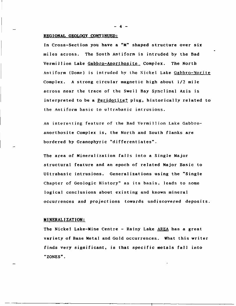
REGIONAL GEOLOGY CONTINUED:
In Cross-Section you have a "M" shaped structure over six
miles across. The South Antiform is intruded by the Bad
Vermillion Lake Gabbro-Anorthos i te Complex. The North
Antiform (Dome) is intruded by the Nickel Lake Gabbro-N'or i t e
Complex. A strong circular magnetic high about 1/2 mile
across near the trace of the Swell Bay Synclinal Axis is
interpreted to be a Peridotite? plug, historically related to
the Antiform basic to ultrabasic intrusions.
An interesting feature of the Bad Vermillion Lake Gabbro-
anorthosite Complex is, the North and South flanks are
bordered by Granophyric "differentiates".
The area of Mineralization falls into a Single Major
structural feature and an epoch of related Major Basic to
Ultrabasic intrusions. Generalizations using the "Single
Chapter of Geologic History" as its basis, leads to some
logical conclusions about existing and known mineral
occurrences and projections towards undiscovered deposits.
MINERALIZATION;
The Nickel Lake-Mine Centre - Rainy Lake AREA has a great
variety of Base Metal and Gold occurrences. What this writer
finds very significant, is that specific metals fall into
"ZONES".
- 5 -
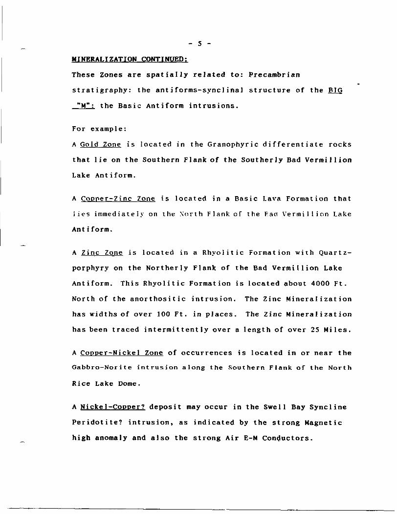
MINERALIZATION CONTINUED:
These Zones are spatially related to: Precambrian
stratigraphy: the antiforms-synclinal structure of the BIG
"M": the Basic Antiform intrusions.
For example:
A Gold Zone is located in the Granophyric differentiate rocks
that lie on the Southern Flank of the Southerly Bad Vermillion
Lake Antiform.
A Copper-Zinc Zone is located in a Basic Lava Formation that
lies immediately on the North Flank of the Eaci Vermillion Lake
Ant i form.
A Zinc Zone is located in a Rhyolitic Formation with Quartz-
porphyry on the Northerly Flank of the Bad Vermillion Lake
Antiform. This Rhyolitic Formation is located about 4000 Ft.
North of the anorthositic intrusion. The Zinc Mineralization
has widths of over 100 Ft. in places. The Zinc Mineralization
has been traced intermittently over a length of over 25 Miles.
A Copper-Nickel Zone of occurrences is located in or near the
Gabbro-Norite intrusion along the Southern Flank of the North
Rice Lake Dome.
A Nickel-Copper? deposit may occur in the Swell Bay Syncline
Peridotite? intrusion, as indicated by the strong Magnetic
high anomaly and also the strong Air E-M Conductors.
- 6 -
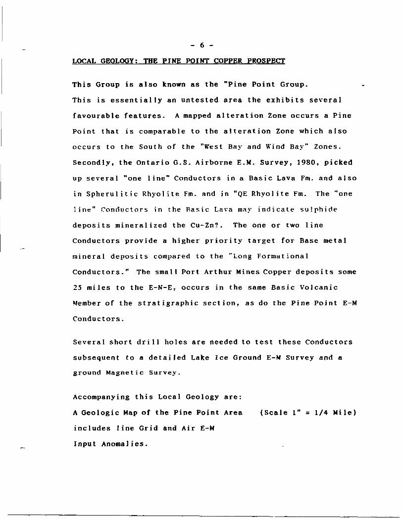
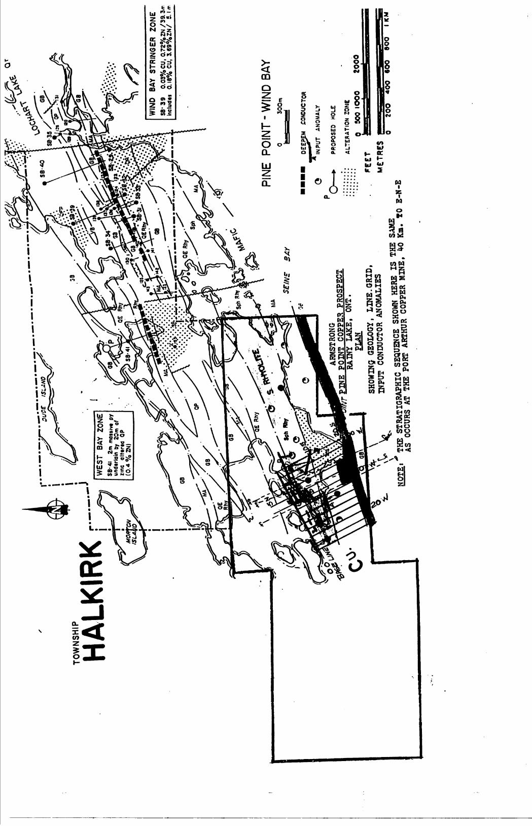
LOCAL GEOLOGY; THE PINE POINT COPPER PROSPECT
This Group is also known as the "Pine Point Group.
This is essentially an untested area the exhibits several
favourable features. A mapped alteration Zone occurs a Pine
Point that is comparable to the alteration Zone which also
occurs to the South of the "West Bay and Wind Bay" Zones.
Secondly, the Ontario G.S. Airborne E.M. Survey, 1980, picked
up several "one line" Conductors in a Basic Lava Fm. and also
in Spherulitic Rhyolite Fm. and in "QE Rhyolite Fm. The "one
line" Conductors in the Basic Lava may indicate sulphide
deposits mineralized the Cu-Zn?. The one or two line
Conductors provide a higher priority target for Base metal
mineral deposits compared to the "Long Formational
Conductors." The small Port Arthur Mines Copper deposits some
25 miles to the E-N-E, occurs in the same Basic Volcanic
Member of the stratigraphic section, as do the Pine Point E-M
Conductors.
Several short drill holes are needed to test these Conductors
subsequent to a detailed Lake Ice Ground E-M Survey and a
ground Magnetic Survey.
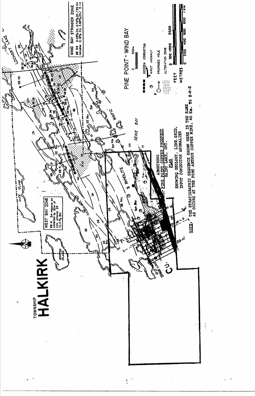
Accompanying this Local Geology are:
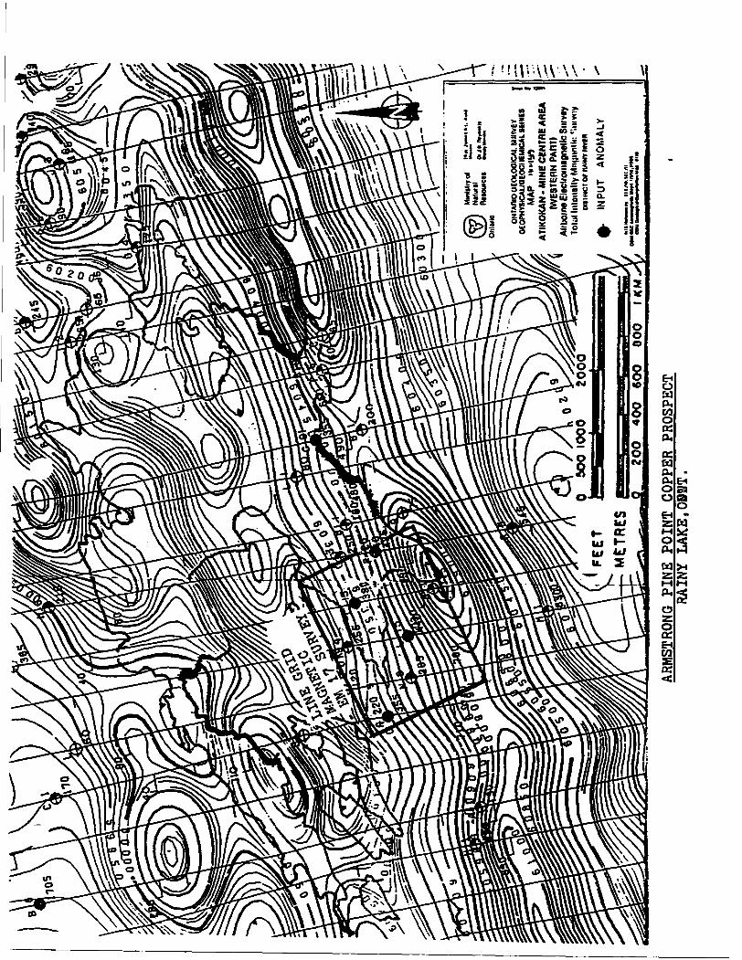
A Geologic Map of the Pine Point Area (Scale l" = 1/4 Mile)
includes line Grid and Air E-M
Input Anomalies.
- 7 -
LOCAL GEOLOGY; THE PINE POINT COPPER PROSPECT CONTINUED;
An M.N.R. Map of the Port Arthur
Copper Mine (Scale l" ^ 50 Ft.).
Geology and Description
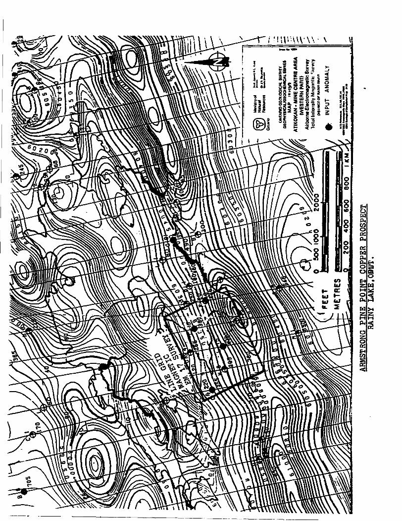
An O.G.S. Airborne Electromagnetic
Survey Map 80499 (Scale l" = 1/4 Mile)
TOW
NS
HIP
HA
LKIR
KSB
-41
2m m
oiiiv
t py
un
dtrla
in b
y 20
m
zinc
al
ttrt
d
OP
(0.4
0/o
ZN
)
WIN
D
BAY
STR
ING
ER
ZO
NE
SB' 3
9
0.03
0XoC
U, 0
.720
X0ZN
/39.
3ir
inel
udts
Q
.18%
CU,
3.6
90X
0Z
N/
5. l
ir.
PINE
PO
INT
- WIN
D BA
YO
300m
^
ARMSTRONG
PINE
POINT CO
PPER
PRO
SPEC
T RAINY
LAKE
, ONT.
PLAN
SHOW
ING
GEOL
OGY,
LINE.GRID,
INPUT
COND
UCTO
R ANOMALIES
Q —
— *
Qgg
PgM
C
ON
DU
CTO
R
INP
UT
A
NO
MA
LY
PRO
POSE
D HO
LE
ALTE
RATI
ON
ZONE
O
SCO
IO
OO
2000
METR
ESNO
TE,'T
HE S
TRAT
KHAP
HIO S
EQUE
NCE
"gg
Ig"y
g1*
S g?
.o B
-H-E
——
—
ORT
ARTH
UR C
Ori^
R m
j.ua.
20
O
400
9OO
60
0
l KM
Quartz—eye Rhyolite
Zn—bearing Bedded Tuff Rhyolite with Stringer Sulfides
Mafic Breccia—Vesicular*
Rhyolite with Chlorite Seams
r.s&ZzZ^?-; Mafic Row•^•-•-i t^^v-,^-^ -
Spherulitic Rhyolite
^bfe^-rv Ch|oritic Qnd Mineralized : •Intermediate/Mafic
Volcanics
•S-..
100 ft
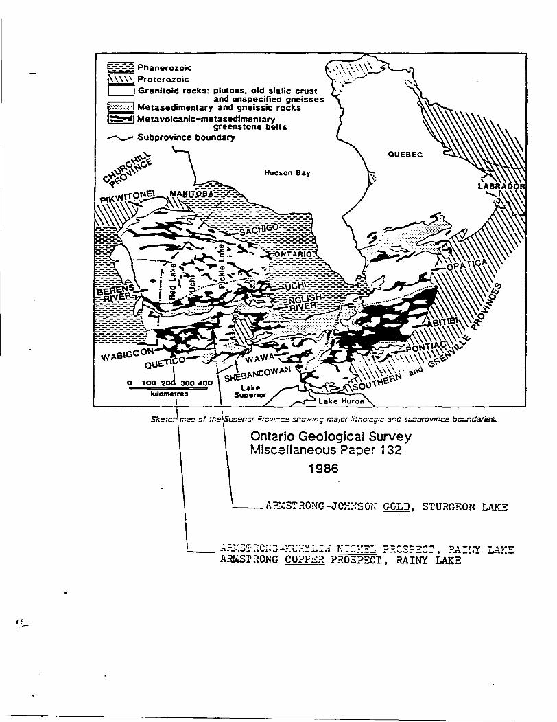
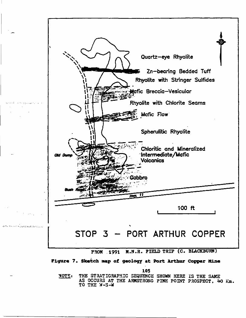
STOP 3 - PORT ARTHUR COPPER
FROM 1991 M.N.R. FIELD TRIP (C. BLACKBURN)
Figure 7. Sketch nap of geology at Port Arthur Copper Mine
105NOTE t THE STRATIGRAPHIC SEQUENCE SHOWN HERE IS THE SAKE
AS OCCURS AT THE ARMSTRONG PINE POINT PROSPECT. HO Km. TO THE W-3-W
807-223-60*0
CHESTER J. KURYLIW. M.Sc.. CONSULTING GBOI.OGISCT
16 INGALL DR.DRYitKN. ONTARIO I"*N 3HT
LOCAL GEOLCQY (con't)
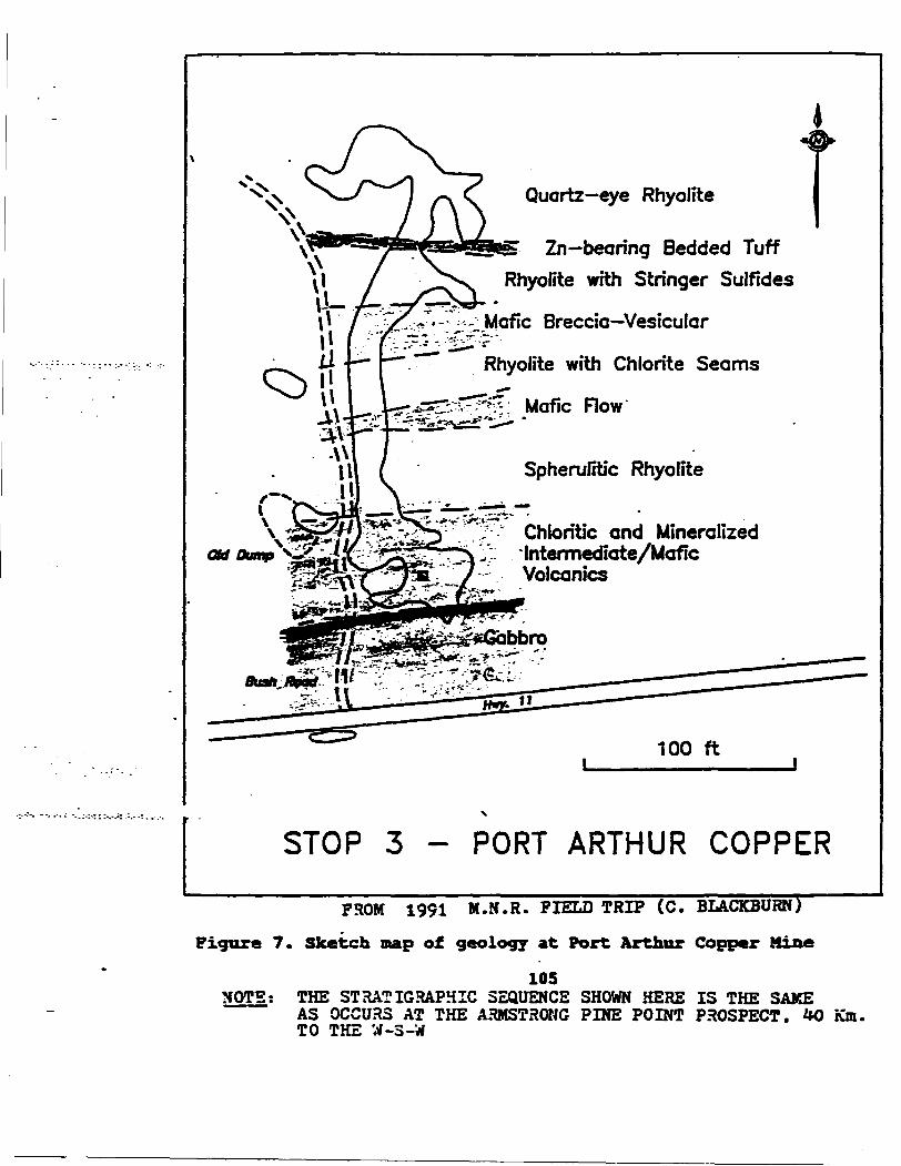
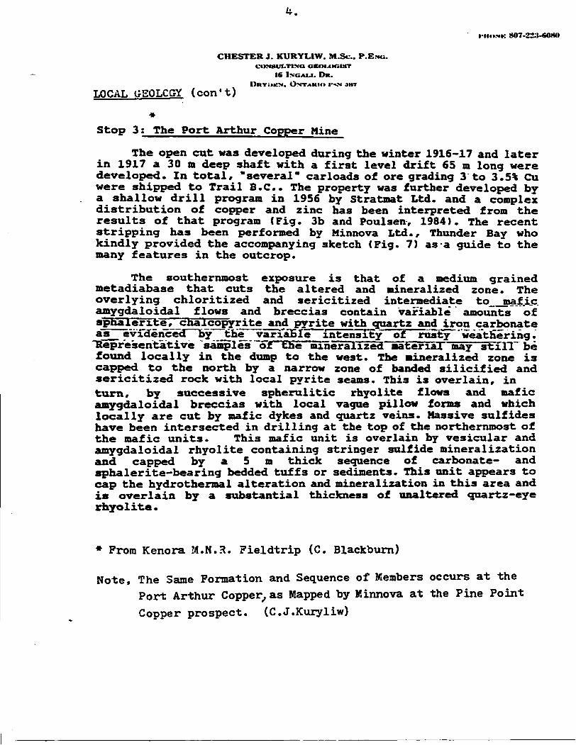
* Stop 3; The Port Arthur Copper Mine
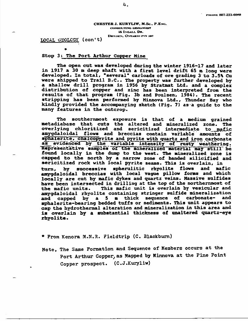
The open cut was developed during the winter 1916-17 and later in 1917 a 30 m deep shaft with a first level drift 65 m long were developed. In total, "several" carloads of ore grading 3 to S.5% Cu were shipped to Trail B.C.. The property was further developed by a shallow drill program in 1956 by Stratmat Ltd. and a complex distribution of copper and zinc has been interpreted from the results of that program (Fig. 3b and Poulsen-, 1984). The recent stripping has been performed by Minnova Ltd., Thunder Bay who kindly provided the accompanying sketch (Pig. 7) as -a guide to the many features in the outcrop.
The southernmost exposure is that of a medium grained metadiabase that cuts the altered and mineralized zone. The overlying chloritized and sericitized intermediate to--mafi.c. amygdaloidal flows and breccias contain variable amounts of spnaiefTte, cnaicopyrite and pyrite with quartz and iron carbonate as^ evidenced by Jth'e ^arxaEI e Intensity of rusty "wea'tHering .
"Representative samples orTlEhe "mineralized materiaT may~sTf:QT~ be found locally in the dump to the west. The mineralized zone is capped to the north by a narrow zone of banded silicified and sericitized rock with local pyrite seams. This is overlain, in turn, by successive spherulitic rhyolite flows and mafic amygdaloidal breccias with local vague pillow forms and which locally are cut by mafic dykes and quartz veins. Massive sulfides have been intersected in drilling at the top of the northernmost of the mafic units. This mafic unit is overlain by vesicular and amygdaloidal rhyolite containing stringer sulfide mineralization and capped by a 5 m thick sequence of carbonate- and sphalerite-bearing bedded tuffs or sediments. This unit appears to cap the hydrothermal alteration and mineralization in this area and is overlain by a substantial thickness of unaltered quartz-eye rhyolite.
* From Kenora J4.N.R. Fieldtrip (C. Blackburn)
Note, The Same Formation and Sequence of Members occurs at the Port Arthur Copper, as Mapped by Minnova at the Pine Point Copper prospect. (C.J.Kuryliw)
ON
TAR
IO O
EOI.O
OIC
Al.
SUM
VtY
OEO
PHYS
ICA
UO
EOC
HEM
ICM
. SE
IMS
MA
P
ATI
KO
KA
N - M
INE
CE
NTR
E A
RE
A(W
ES
TER
N P
AR
T)Ai
rbor
ne E
lect
rom
agne
tic S
urve
ylo
lul I
nlon
slly
Mii(
|imlh
: 'in
ivoy
oniH
ir.r o
r rui
Nv in
vrn
FEET
ME
TRES
INP
UT
A
NO
MA
LY
200
40
0
600
ARM
STRO
NG P
INE
POIN
T CO
PPER
PRO
SPEC
T RA
INY
LAKE
.OBN
T.
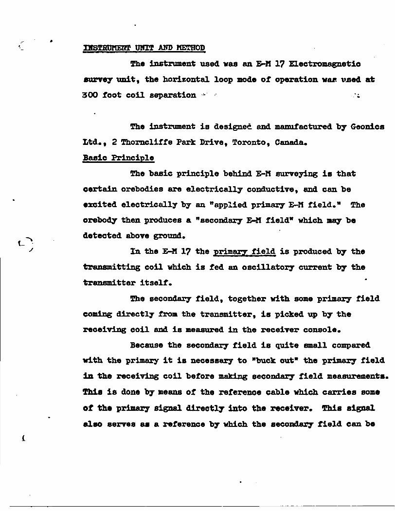
IBSTHDruatf UMU AND
The instrument used was an E-M 17 Electromagnetic
survey unit, the horizontal loop mode of operation wa*. used at
300 foot coil separation - ';
The instrument is designed and manufactured by Geonics
Ltd., 2 Thorncliffe Park Drive, Toronto, Canada.
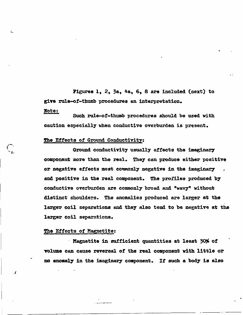
Basic Principle
The basic principle behind E-M surveying is that
certain orebodies are electrically conductive, and can be
excited electrically by an "applied primary E-M field." The
orebody then produces a "secondary E-M field" which may be
- detected above ground. t- -s In the E-M 17 the primary field is produced by the
transmitting coil which is fed an oscillatory current by the
transmitter itself.
The secondary field, together with some primary field
coming directly from the transmitter, is picked up by the
receiving coil and is measured in the receiver console.
Because the secondary field is quite small compared
with the primary it is necessary to "buck out" the primary field
in the receiving coil before main Tig secondary field measurements.
This is done by means of the reference cable which carries some
of the primary signal directly into the receiver. This signal
also serves as a reference by which the secondary field can be
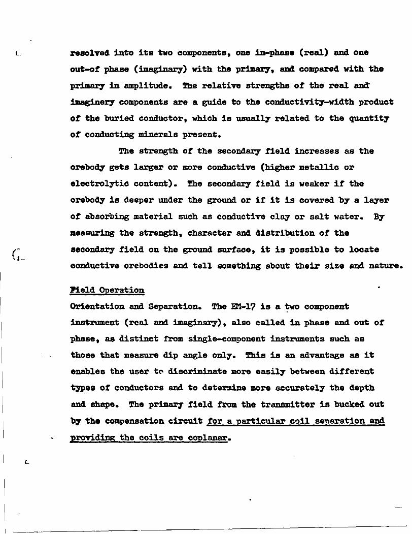
L resolved into its two components, one in-phase (real) and one
out-of phase (imaginary) with the primary, and compared with the
primary in amplitude. The relative strengths of the real and*
imaginary components are a guide to the conductivity-width product
of the buried conductor, which is usually related to the quantity
of conducting minerals present.
The strength of the secondary field increases as the
orebody gets larger or more conductive (higher metallic or
electrolytic content). The secondary field is weaker if the
orebody is deeper under the ground or if it is covered "by a layer
of absorbing material such as conductive clay or salt water. By
measuring the strength, character and distribution of the
f- secondary field on the ground surface, it is possible to locate U-
conductive orebodies and tell something about their size and nature.
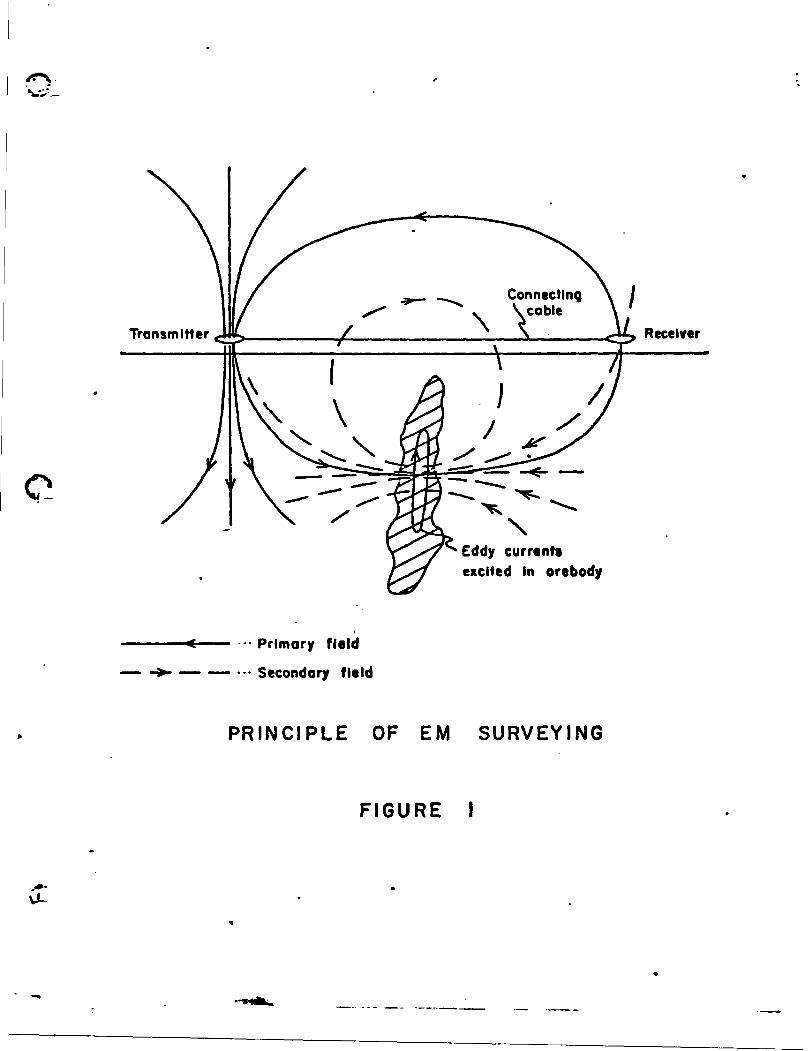
Field Operation
Orientation and Separation. The En-1? is a two component
instrument (real and imaginary), also called in phase and out of
phase, as distinct from single-component instruments such as
those that measure dip angle only. This is an advantage as it
enables the user to discriminate more easily between different
types of conductors and to determine more accurately the depth
and shape. The primary field from the transmitter is bucked out
by the compensation circuit for a particular coil separation and
providing the coils are coplanar.
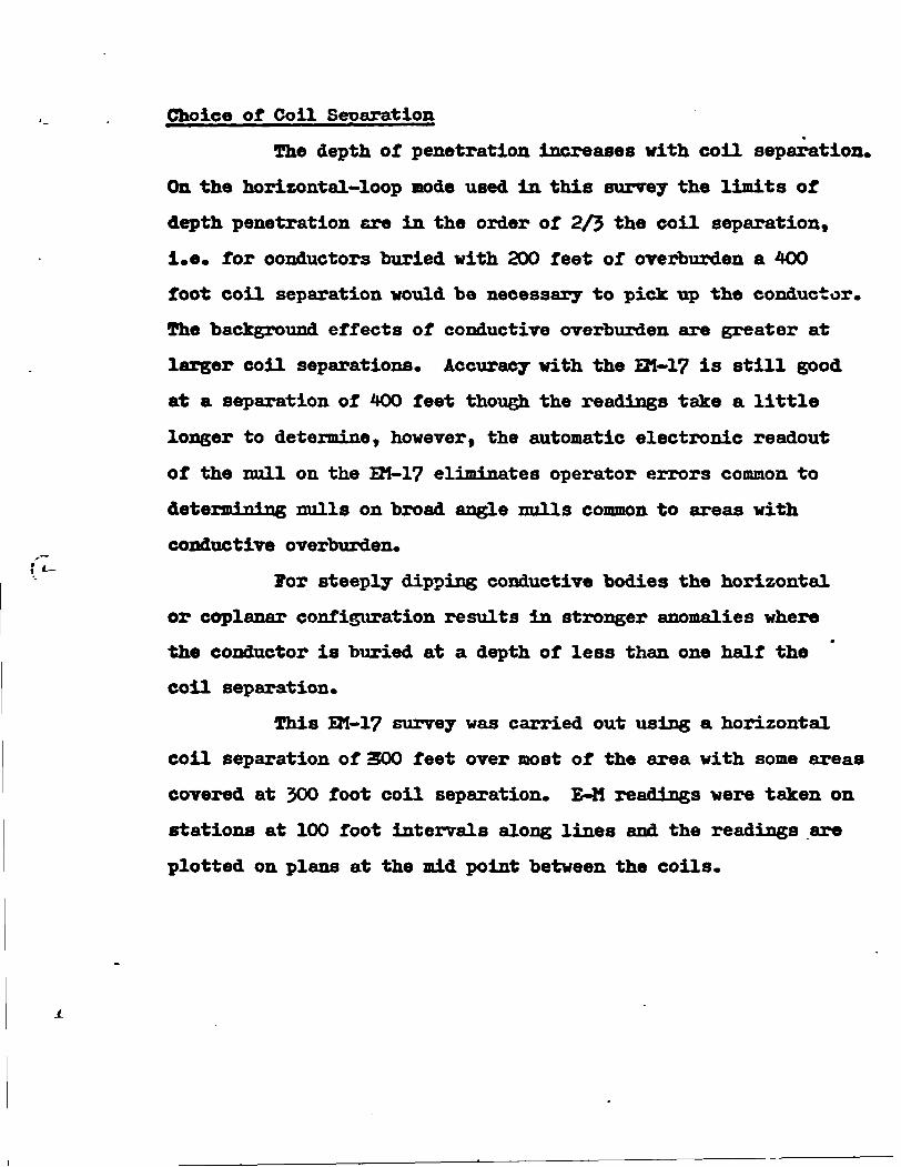
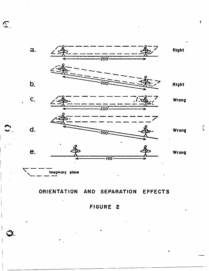
Choice of Coil Separation*
The depth of penetration increases with coil separation.
On the horizontal-loop mode used in this survey the limits of
depth penetration are in the order or 2/3 the coil separation,
i.e. for conductors buried with 200 feet of overburden a 400
foot coil separation would be necessary to pick up the conductor.
The background effects of conductive overburden are greater at
larger coil separations. Accuracy with the HI-1? is still good
at a separation of 400 feet though the readings take a little
longer to determine, however, the automatic electronic readout
of the null on the EM-1? eliminates operator errors common to
determining nulls on broad angle nulls common to areas with
conductive overburden.
For steeply dipping conductive bodies the horizontal
or coplanar configuration results in stronger anomalies where
the conductor is buried at a depth of less than one half the
coil separation.
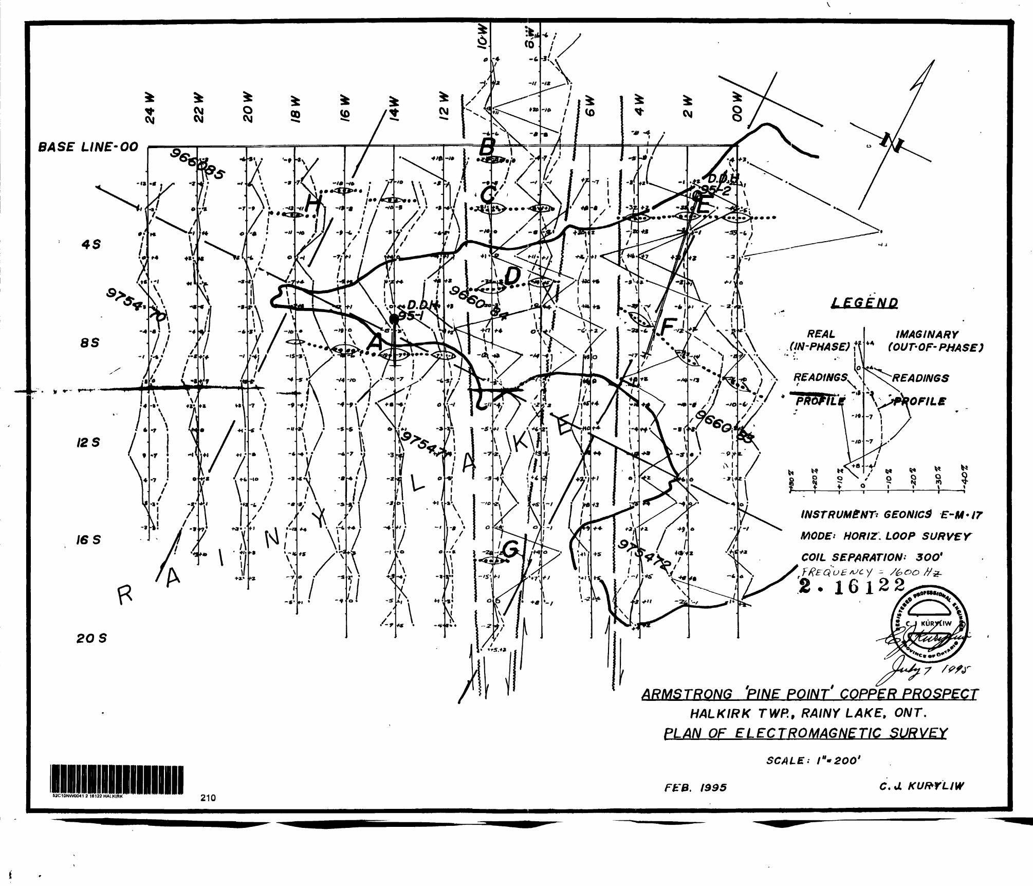
This QI-17 survey was carried out using a horizontal
coil separation of 300 feet over most of the area with some areas
covered at 500 foot coil separation. E-M readings were taken on
stations at 100 foot intervals along lines and the readings are
plotted on plans at the mid point between the coils.
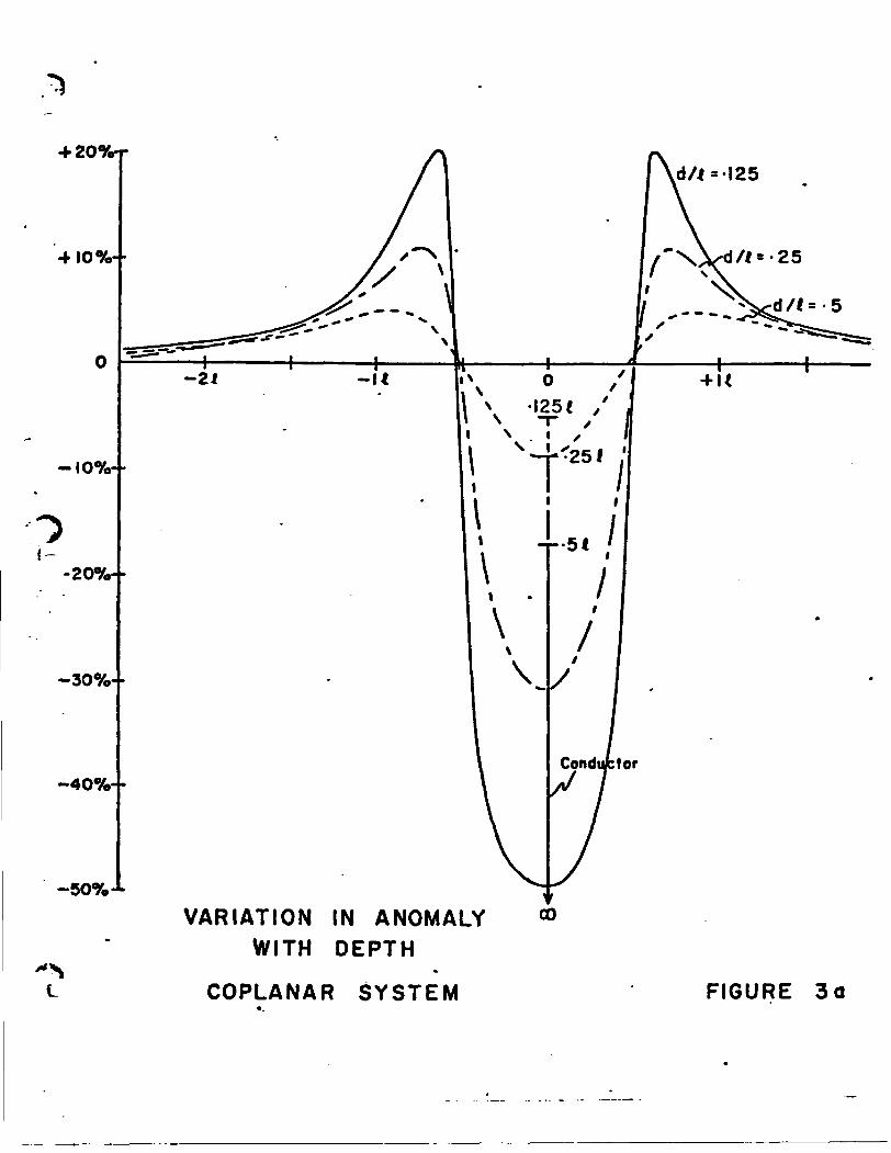
Figures l, 2, 3a. *at 6, 8 are included (next) to
give rule-of-thumb procedures an interpretation.
gote;Such rule-of-thumb procedures should be used with
caution especially when conductive overburden is present.
The Effects of Ground Conductivity;
Ground conductivity usually affects the imaginary
component more than the real. They can produce either positive
or negative effects most commonly negative in the imaginary
and positive in the real component. The profiles produced by
conductive overburden are commonly broad and "wavy" without
distinct shoulders. The anomalies produced are larger at the
larger coil separations and they also tend to be negative at the
larger coil separations.
The Effects of Magnetite;
Magnetite in sufficient quantities at least 3O# of
volume can cause reversal of the real component with little or
no anomaly in the imaginary component. If such a body ia also
/r
Connectinq \ l . \coble X '
\Eddy currents excited In orebody
Primary field— -*- — — --- Secondary field
PRINCIPLE OF EM SURVEYING
FIGURE l
a.
b.
c.
d.
e.
-200-
-200-
V \
Rlght
Right
Wrong
Wrongx V.
Wrong
Imaginary plane
ORIENTATION AND SEPARATION EFFECTS
FIGURE 2
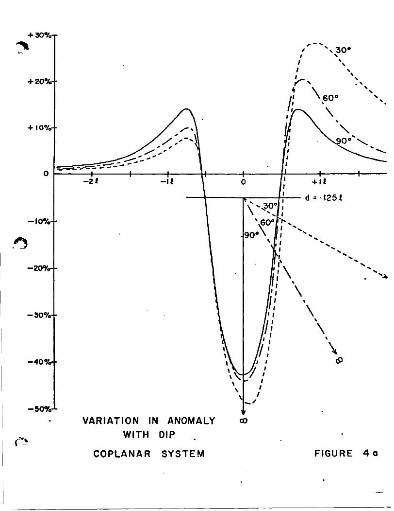
-soy.-*-VARIATION IN ANOMALY
WITH DEPTH
COPLANAR SYSTEM FIGURE 3a
•f 30%-r
•1-207*--
I070--
-107.- -
-307o- -
-407*- -
-507.J-
\\\
tf)
VARIATION IN ANOMALY WITH DIP
COPLANAR SYSTEM FIGURE 4 o
IO+
:vVLF (EM-16)
5-4-
104
19-1-
^.*—v
x;----/ \y
V-,
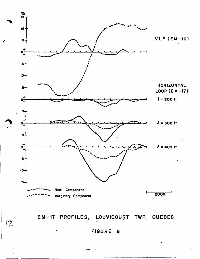
\s..Real Component Imaginary Component
HORIZONTAL LOOP (EM-17)
X - 200 ft.
300 ft.
^'^*^fcl i 2 400 ft.
200ft.
EM-17 PROFILES, LOUVICOURT TWP. QUEBEC
FIGURE 6
AXIS
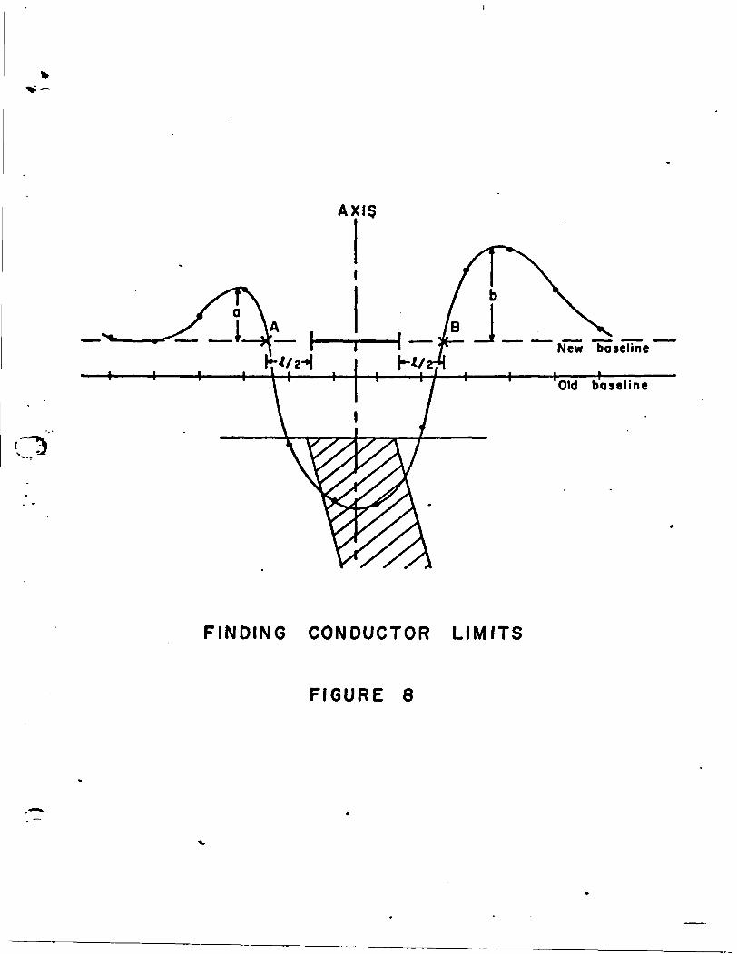
FINDING CONDUCTOR LIMITS
FIGURE 8
- 8 -
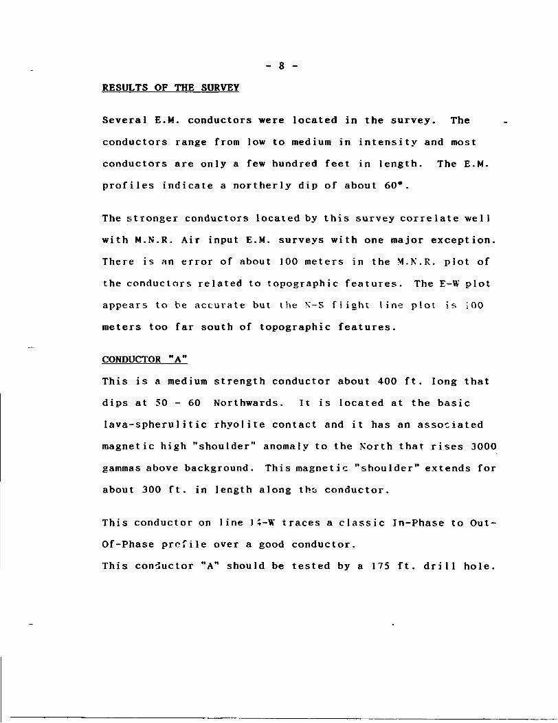
RESULTS OF THE SURVEY
Several E.M. conductors were located in the survey. The
conductors range from low to medium in intensity and most
conductors are only a few hundred feet in length. The E.M.
profiles indicate a northerly dip of about 60*.
The stronger conductors located by this survey correlate well
with M.N.R. Air input E.M. surveys with one major exception.
There is an error of about 100 meters in the M.K.R. plot of
the conductors related to topographic features. The E-W plot
appears to be accurate but the N-S flight line plot is 100
meters too far south of topographic features.
CONDUCTOR "A"
This is a medium strength conductor about 400 ft. long that
dips at 50 - 60 Northwards. It is located at the basic
lava-spherul i tic rhyolite contact and it has an associated
magnetic high "shoulder" anomaly to the North that rises 3000
gammas above background. This magnetic "shoulder" extends for
about 300 ft. in length along tht conductor.
This conductor on line l i-W traces a classic In-Phase to Out-
Of-Phase profile over a good conductor.
This conductor "A" should be tested by a 175 ft. drill hole.
- 9 -
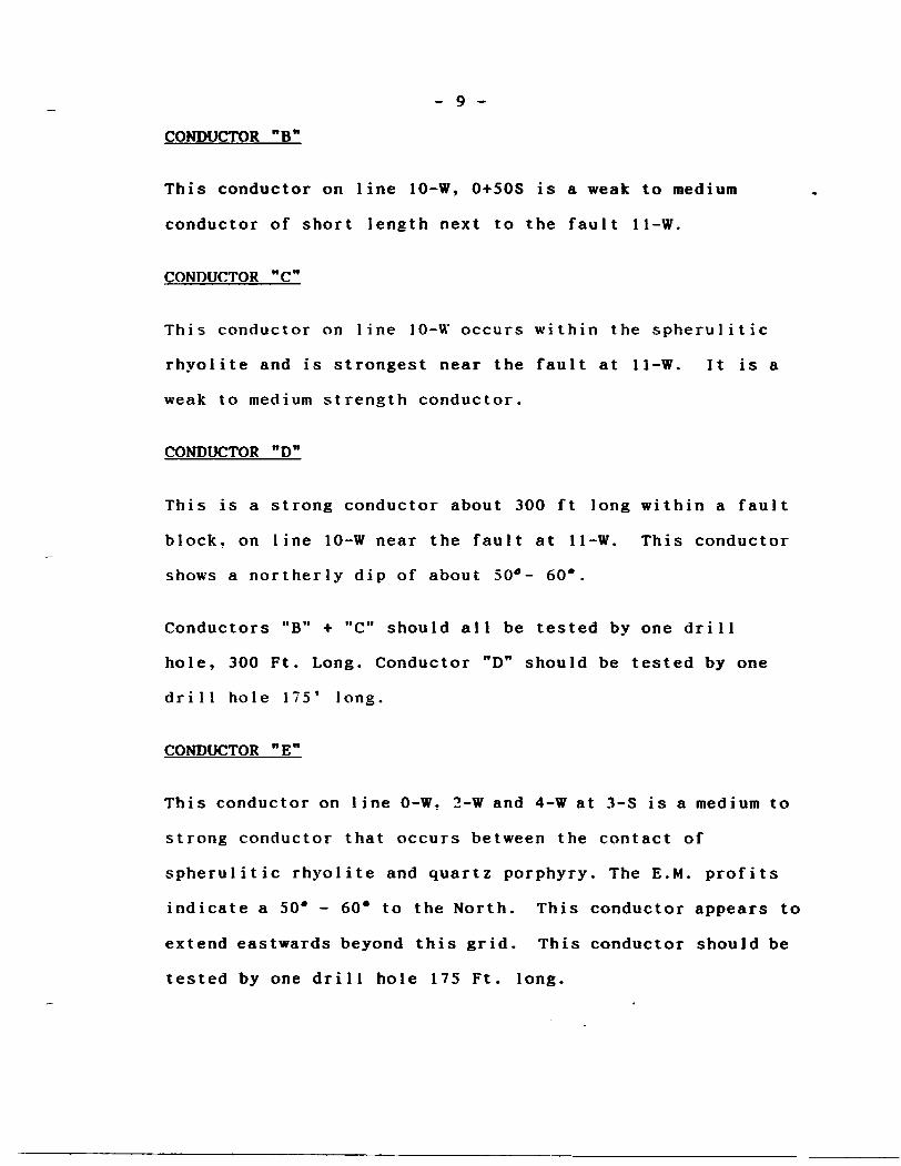
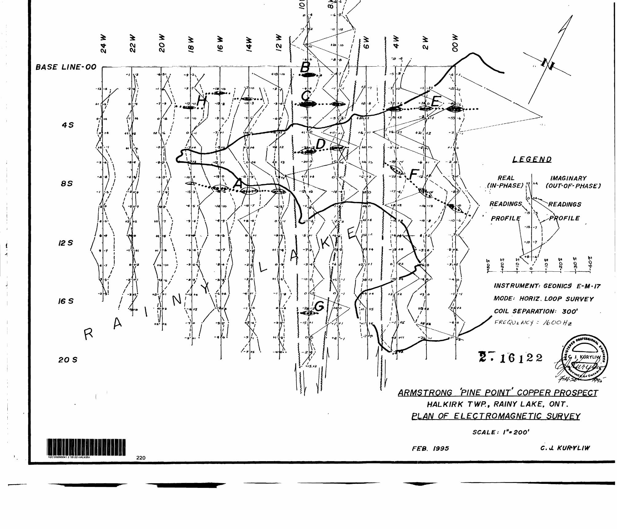
CONDUCTOR "B"
This conductor on line 10-W, 0+50S is a weak to medium
conductor of short length next to the fault 11-W.
CONDUCTOR "C"
This conductor on line 10-W occurs within the spherulitic
rhyolite and is strongest near the fault at 11-W. It is a
weak to medium strength conductor.
CONDUCTOR "D"
This is a strong conductor about 300 ft long within a fault
block, on line 10-W near the fault at 11-W. This conductor
shows a northerly dip of about 50*- 60*.
Conductors "B" * " C" should all be tested by one drill
hole, 300 Ft. Long. Conductor "D" should be tested by one
drill hole 175' long.
CONDUCTOR "E"
This conductor on line 0-W. 2-W and 4-W at 3-S is a medium to
strong conductor that occurs between the contact of
spherulitic rhyolite and quartz porphyry. The E.M. profits
indicate a 50* - 60* to the North. This conductor appears to
extend eastwards beyond this grid. This conductor should be
tested by one drill hole 175 Ft. long.
- 10 -
RESULTS OF THE SURVEY CONTINUED
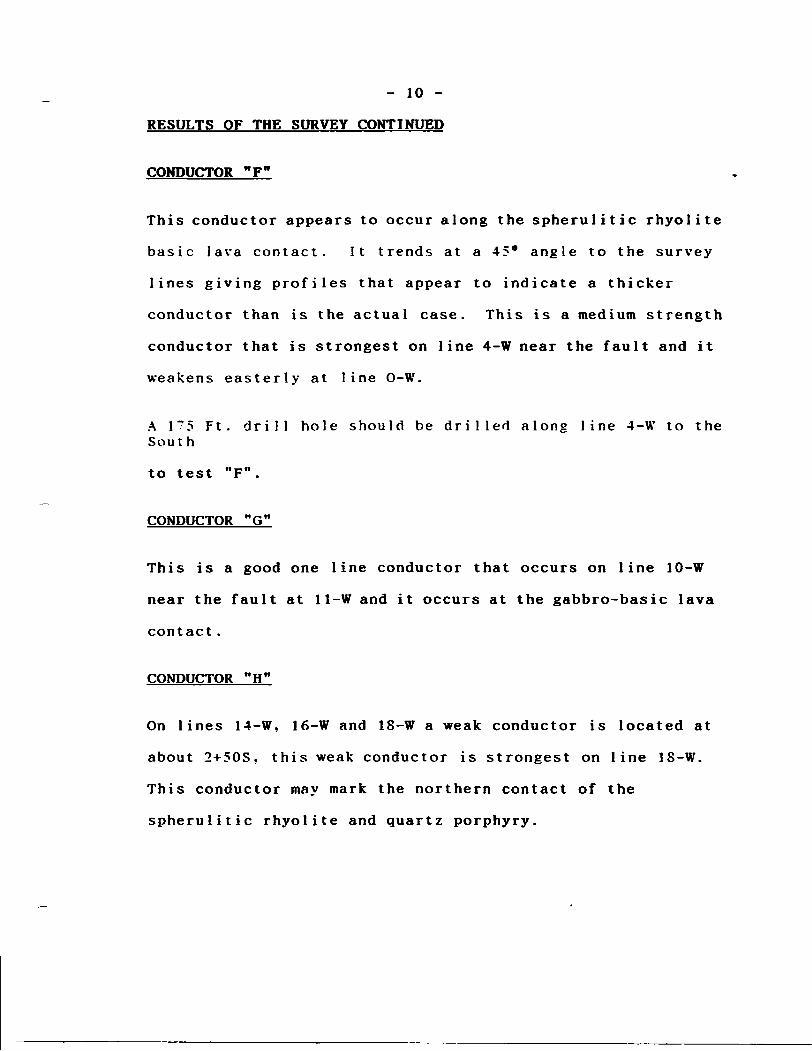
CONDUCTOR "F"
This conductor appears to occur along the spherulitic rhyolite
basic lava contact. It trends at a 45* angle to the survey
lines giving profiles that appear to indicate a thicker
conductor than is the actual case. This is a medium strength
conductor that is strongest on line 4-W near the fault and it
weakens easterly at line O-W.
A 1"5 Ft. drill hole should be drilled along line 4-W to the South
to test "F".
CONDUCTOR "G"
This is a good one line conductor that occurs on line 10-W
near the fault at 11-W and it occurs at the gabbro-basic lava
contact .
CONDUCTOR "H"
On lines 14-W, l6-W and 18-W a weak conductor is located at
about 2+50S, this weak conductor is strongest on line 18-W.
This conductor may mark the northern contact of the
spherulitic rhyolite and quartz porphyry.
- 11 -
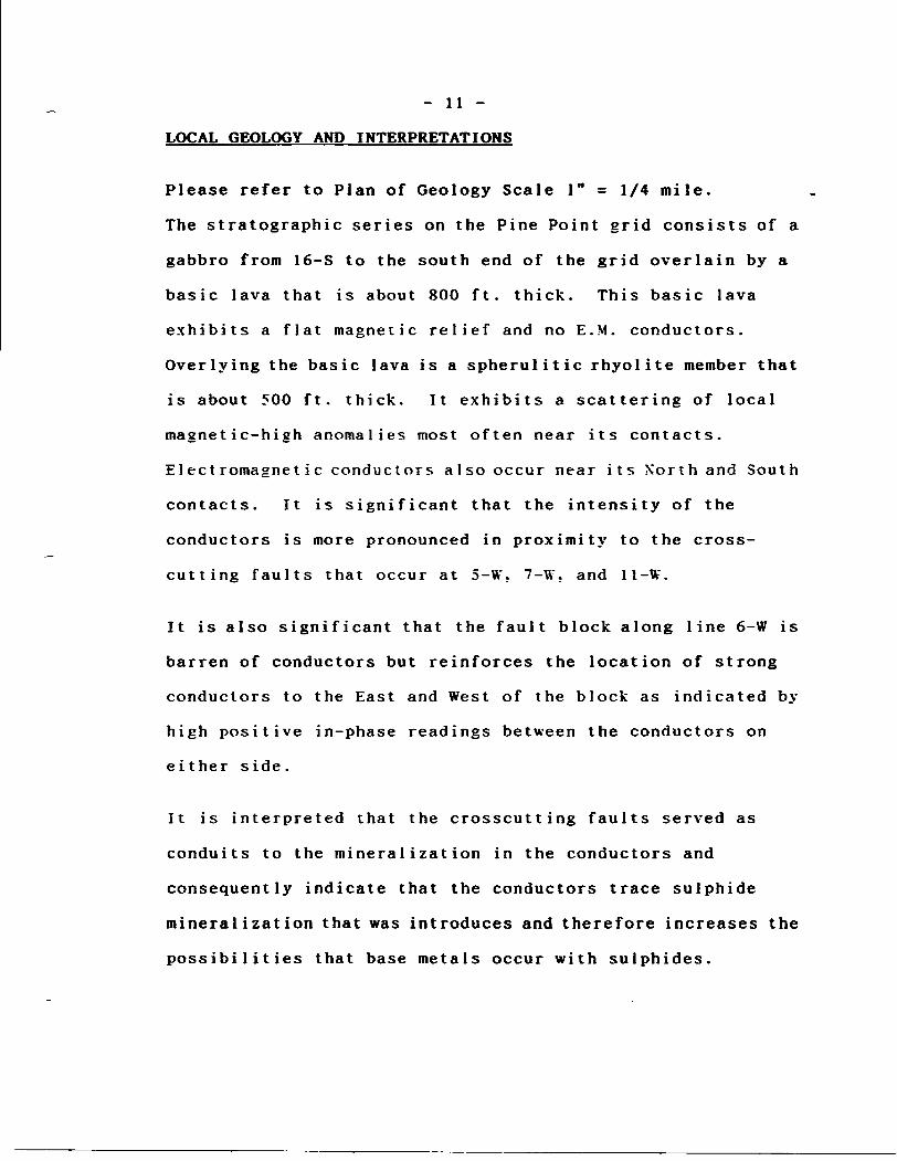
LOCAL GEOLOGY AND INTERPRETATIONS
Please refer to Plan of Geology Scale l" = 1 /4 mile.
The stratigraphic series on the Pine Point grid consists of a
gabbro from 16-S to the south end of the grid overlain by a
basic lava that is about 800 ft. thick. This basic lava
exhibits a flat magnetic relief and no E.M. conductors.
Overlying the basic lava is a spherulitic rhyolite member that
is about 500 ft. thick. It exhibits a scattering of local
magnetic-high anomalies most often near its contacts.
Electromagnetic conductors also occur near its North and South
contacts. It is significant that the intensity of the
conductors is more pronounced in proximity to the cross
cutting faults that occur at 5-W. 7-W. and 11-W.
It is also significant that the fault block along line 6-W is
barren of conductors but reinforces the location of strong
conductors to the East and West of the block as indicated by
high positive in-phase readings between the conductors on
e i ther s ide.
It is interpreted that the crosscutting faults served as
conduits to the mineralization in the conductors and
consequently indicate that the conductors trace sulphide
mineralization that was introduces and therefore increases the
possibilities that base metals occur with sulphides.
- 12 -
CONCLUSIONS;
The horizontal loop E.M. survey succeeded in locating and
defining the conductors indicated by the M.K.R. air input E.M.
survey. These conductors occur in a favourable known
environment for base metals mineralization. These conductors
represent high priority targets.
February 20, 1995 Chester J. Kuryliw
- 13 -
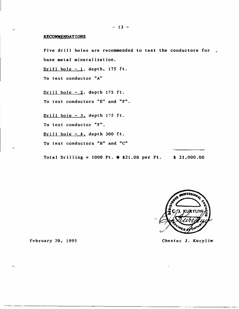
RECOMMENDATIONS
Five drill holes are recommended to test the conductors for
base metal mineralization.
Drill hole - 1. depth, 175 ft.
To test conductor "A"
Drill hole - 2. depth 175 ft.
To test conductors "E" and "F".
Drill hole - 3. depth 175 ft.
To test conductor "F".
Drill hole - 4. depth 300 ft.
To test conductors "B" and "C"
Total Drilling = 1000 Ft. 6 $21.00 per Ft S 21,000.00
February 20, 1995 Chester J. Kuryliw
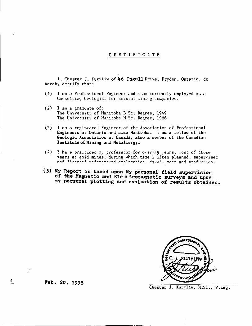
CERTIFICATE
I, Chester J. Kuryliw of 1*6 Ingall Drive, Dryden, Ontario, do hereby certify that:
(1) I am a Professional Engineer and I am currently employed as a Consulting Geologist for several mining companies.
(2) I am a graduate of:The University of Manitoba B.Se. Degree, 1949 The University of Manitoba M.Se. Degree, 1966
(3) I am a registered Engineer of the Association of Professional Engineers of Ontario and also Manitoba. I am a fellow of the Geologic Association of Canada, also a member of the Canadian Institute of Mining and Metallurgy.
(A) I have practiced my profession for G-. arlv5 years, most of thoseyears at gold mines, during which tine l often planned, supervisednn-j -"^ir^cT^^ *ir. "ierc r "".'jrd exclorst^'^r.. d o vt^l , - J ~\ t ~.i. ard orO'J M r ' ;-'~.
(5) My Report is based upon My personal field supervision of the Magnetic and Ele c tromagnetic surveys and upon my personal plotting and evaluation of results obtained,
Feb. 20, 1995Chester J. Kuryliw, M.Se., P.Eng.
PHONE 807-223-6080
CHESTER J. KURYLJW. M.Sc.. P.ENG. CONSULTfNG CBOIXMSMTT
46 INGALL DR. DRYDEN. ONTARIO PON aB7
S2C10NW0041 2.16122 HALKIRK 020
REPORT
ON
ARMSTRONG - COPPER PROSPECT
HALKIRK TWP. RAINY LAKE AREA OF ONTARIO
GROUND MAGNETIC SURVEY
FEBRUARY 20, 1995 CHESTER J. KURYLIW
o 1 6 l 2 2
S2C10NW0041 2 16122 HALKIRK 020C
- 2 -
TABLE OF CONTENTS
Project Location
Location Maps
Access to Project Site
Regional Geology and Mineralization
Introduct ion
Instrument, Unit and Method
Results of the Survey
Conclus ions
Recommendat ions
Certificate
Plan of Magnetic Survey Scale l" = 200
- 3 -
(a) PROJECT LOCATION
PINE POINT COPPER PROSPECT; Halkirk Twp., Rainy Lake, Ont.
Located on Claim Map G-380S of Halkirk and Farrington Twps.
N.T.S. C-ll, Latitude 48e 38N., Longitude 93*01* W.
(b) LOCATION MAPS:
Claim Map. Halkirk fc Farrington Twps. (scale: l" = 1 /2 mile)
Ontario Geology Survey Map (scale: l" = 340 Kms)
Road Map and Geology (scale: l" s 25 Kms)
(c) ACCESS TO PROJECT SITE:
There is a good access to the Property from Dryden. 151 Kms to
the South from Dryden along Hwy. 502 to the junction of
Hwy.ll, then 5 Kms East along Hwy 11 to Bears Pass, then over
ice by Ski-doo for 5 Kms. to the drill site.
(d) DESCRIPTION OF PROPERTY: PINE POINT COPPER. HALKIRK TWP.
CI. Blk.K-1150126, K-996076, K-996077, K-996078, K-996079,
K-996080, K-9960S1. K-996082, K-9960S3, K-9960S4, K-9960S5,
K-975470, K-975471, K-975472. A total of 14 Claims (25 Claim
units).
Owned 9055 by George Armstrong, and ^ 0% by Chester J. Kuryliw.
(e) DESCRIPTION OF REGIONAL AND LOCAL GEOLOGY:
REGIONAL GEOLOGY:
The Area is located in the Precambrian Wabigoon sub-province.
This Area embraces two major East-North-East trending
Ant i forms. separated by the Swell Bay steep sided Svnclinal
trough.
SOU'
RA
NGE
""^
•gif
ifK
m* H
* *M
rlA
LK
IR
K
SOUT
H RA
NGE'
. l 918
186
9*75
67
p279
66
(Bre
ete
.__
P————'——
\*
'^(M^
.•5*161
T50I27
LIN
E G
RID
It
DRIL
LIN.
,6 A
REA
^
DRILLING A
REA
50 26
ARMSTRONG
90*
HAL
KIR
KFA
RRIN
GTO
NCL
AIM MAP
GEORGE ARMSTRONG HOLD
INGS
_ N
TS,
C-U
. ......
Min
istry
of
Natu
ral
Reso
urce
s(
i*:
" -
; l-
}' ,-
SCALE: 9
tooi
ooo
looo
ARMS
TRON
G KURYLIW
50^
OWNE
RSHI
P
g3
/r-'......Au--^-
*^tP^jtW \ r.-O&wH .•/^S-JLi-S.:-•^---ia-**^...'-.. v N -7 •a**T-*'~ —
r^ iXvhi-'-P-^c;^ v-rT'
^^^?^^fe^J:
F^-^^r-Ki 'r"';' ^--^^r- racr"" ^^a^**^i'-**d!5* -:;**'-z?—,*e- ^ I^T^feP^Ss'iNU^. 7 •^ssfc^?^^^?™ !.-.---------. TSssS* ---'*; r -..^'2*ftU.- ^ta^w.-.'^ ^Sfr3^^''""" ^-^ ^-C^rv^''' 7:-^-*
,^3^^'"ll "3 - - ^^^--^M
SCALE : 1 M *25 Km. PLAN O? ACCESS ROUTSS TO ARMSTRONG DRILLING 1995
-; Phanerozoic ProterozoicGranitoid rocks: plutons. old sialic crust " v
and unspecified gneisses Metasedimentary and gneissic rocks
l Metavolcanic-metasedimentarygreenstone belts
Subprovince boundary
CT."u^r"—3wv^r^-r:
^* ^t r.
'-^ieriiP'V^\\m-5T-- ^PO^ACV^ ^^\\\\\^
vLake Huron\
S'xercr. mar c.' :r.e\Svcsr:zr ~rsw.~cs sn:vfirg frater :i;nctcgic arc sacorovir.cs Scur.tiaries.
Ontario Geological Survey Miscellaneous Paper 132
1986
.AHKSTSONG-JCKXSGK GOLD. STURGEON LAKE
A?j.:3THc;;c--?:ur.YLiw NI:?:;L PROSPECT, RAII.T LAKEA-ObSTRONG COFFER PROSPECT, RAINY LAKE
- 4 -
REGIONAL GEOLOGY CONTINUED:
In Cross-Section you have a "M" shaped structure over six
miles across. The South Antiform is intruded by the Bad
Vermillion Lake Gabbro-Anorthosite Complex. The North
Antiform (Dome) is intruded by the Nickel Lake Gabbro-Nori te
Complex. A strong circular magnetic high about 1/2 mile
across near the trace of the Swell Bay Synclinal Axis is
interpreted to be a Peridot ite? plug, historically related to
the Antiform basic to ultrabasic intrusions.
An interesting feature of the Bad Vermillion Lake Gabbro-
anorthosite Complex is, the North and South flanks are
bordered by Granophyric "differentiates".
The area of Mineralization falls into a Single Major
structural feature and an epoch of related Major Basic to
Ultrabasic intrusions. Generalizations using the "Single
Chapter of Geologic History" as its basis, leads to some
logical conclusions about existing and known mineral
occurrences and projections towards undiscovered deposits.
MINERALIZATION;
The Nickel Lake-Mine Centre - Rainy Lake AREA has a great
variety of Base Metal and Gold occurrences. What this writer
finds very significant, is that specific metals fall into
"ZONES".
- 5 -
MINERALIZATION CONTINUED;
These Zones are spatially related to: Precambrian
stratigraphy: the antiforms-synclinal structure of the BIG
"M": the Basic Antiform intrusions.
For example:
A Gold Zone is located in the Granophyric differentiate rocks
that lie on the Southern Flank of the Southerly Bad Vermillion
Lake Antiform.
A Copper-Zinc Zone is located in a Basic Lava Formation that
lies immediately on the North Flank of the Bad Vermillion Lake
Antiform.
A Zinc Zone is located in a Rhyolitic Formation with Quartz-
porphyry on the Northerly Flank of the Bad Vermillion Lake
Antiform. This Rhyolitic Formation is located about 4000 Ft.
North of the anorthositic intrusion. The Zinc Mineralization
has widths of over 100 Ft. in places. The Zinc Mineralization
has been traced intermittently over a length of over 25 Miles.
A Copper-Nickel Zone of occurrences is located in or near the
Gabbro-Norite intrusion along the Southern Flank of the North
Rice Lake Dome.
A Nickel-Copper? deposit may occur in the Swell Bay Syncline
Peridotite? intrusion, as indicated by the strong Magnetic
high anomaly and also the strong Air E-M Conductors.
- 6 -
LOCAL GEOLOGY: THE PINE POINT COPPER PROSPECT
This Group is also known as the "Pine Point Group.
This is essentially an untested area the exhibits several
favourable features. A mapped alteration Zone occurs a Pine
Point that is comparable to the alteration Zone which also
occurs to the South of the "West Bay and Wind Bay" Zones.
Secondly, the Ontario G.S. Airborne E.M. Survey, 1980, picked
up several "one line" Conductors in a Basic Lava Fm. and also
in Spherulitic Rhyolite Fm. and in "QE Rhyolite Fm. The "one
line" Conductors in the Basic Lava may indicate sulphide
deposits mineralized the Cu-Zn?. The one or two line
Conductors provide a higher priority target for Base metal
mineral deposits compared to the "Long Formational
Conductors." The small Port Arthur Mines Copper deposits some
25 miles to the E-N-E, occurs in the same Basic Volcanic
Member of the stratigraphic section, as do the Pine Point E-M
Conductors.
Several short drill holes are needed to test these Conductors
subsequent to a detailed Lake Ice Ground E-M Survey and a
ground Magnetic Survey.
Accompanying this Local Geology are:
A Geologic Map of the Pine Point Area (Scale l" = 1/4 Mile)
includes line Grid and Air E-M
Input Anomalies.
- 7 -
LOCAL GEOLOGY: THE PINE POINT COPPER PROSPECT CONTINUED:
An M.N.R. Map of the Port Arthur
Copper Mine (Scale l" * 50 Ft.).
Geology and Description
An O.G.S. Airborne Electromagnetic
Survey Map 80499 (Scale l" = 1 /4 Mile)
- 3 -
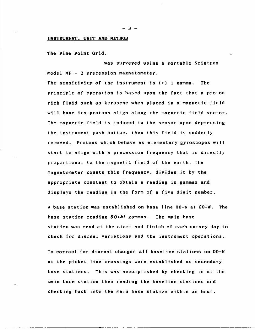
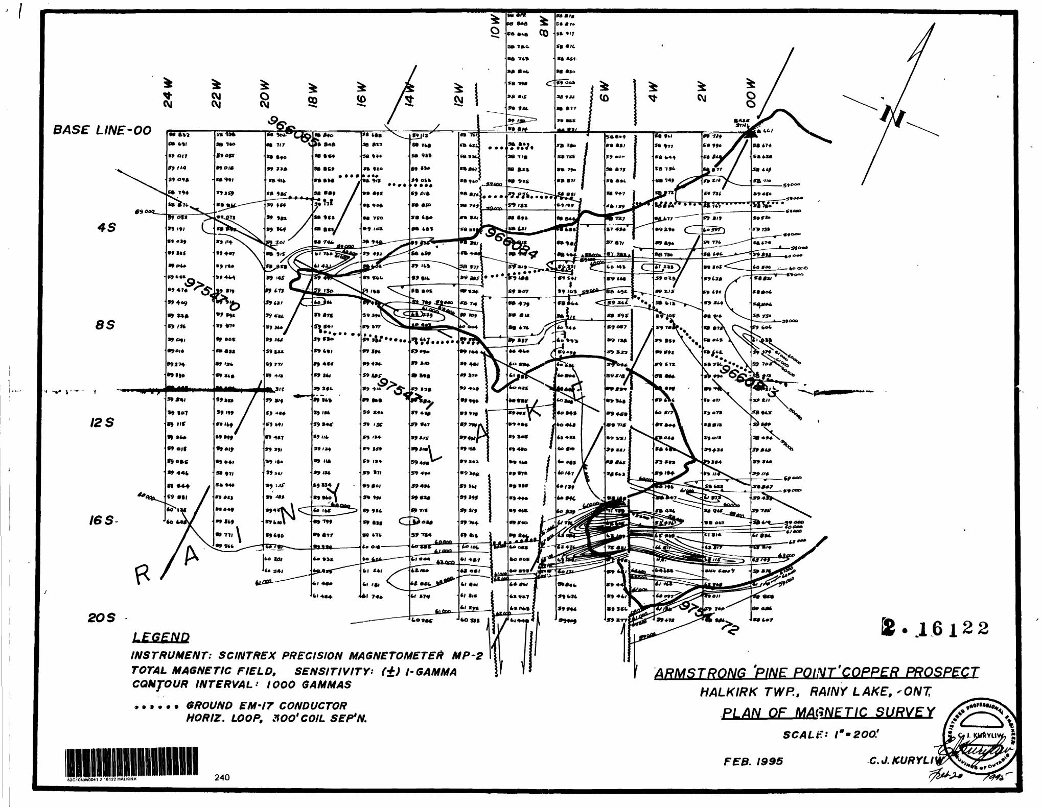
INSTRUMENT. UNIT AND METHOD
The Pine Point Grid,
was surveyed using a portable Scintrex
model MP - 2 precession magnetometer.
The sensitivity of the instrument is (+J l gamma. The
principle of operation is based upon the fact that a proton
rich fluid such as kerosene when placed in a magnetic field
will have its protons align along the magnetic field vector.
The magnetic field is induced in the sensor upon depressing
the instrument push button, then this field is suddenly
removed. Protons which behave as elementary gyroscopes will
start to align with a precession frequency that is directly
proportional to the magnetic field of the earth. The
magnetometer counts this frequency, divides it by the
appropriate constant to obtain a reading in gammas and
displays the reading in the form of a five digit number.
A base station was established on base line 00-N at 00-W. The
base station reading 58&M gammas. The main base
station was read at the start and finish of each survey day to
check for diurnal variations and the instrument operations.
To correct for diurnal changes all baseline stations on 00-N
at the picket line crossings were established as secondary
base stations. This was accomplished by checking in at the
main base station then reading the baseline stations and
checking back into the main base station within an hour.
- 4 -
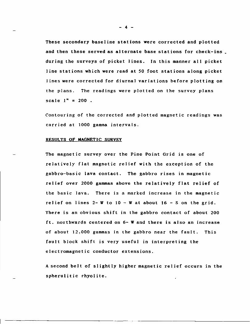
These secondary baseline stations were corrected and plotted
and then these served as alternate base stations for check-ins
during the surveys of picket lines. In this manner all picket
line stations which were read at 50 foot stations along picket
lines were corrected for diurnal variations before plotting on
the plans. The readings were plotted on the survey plans
scale l" = 200 .
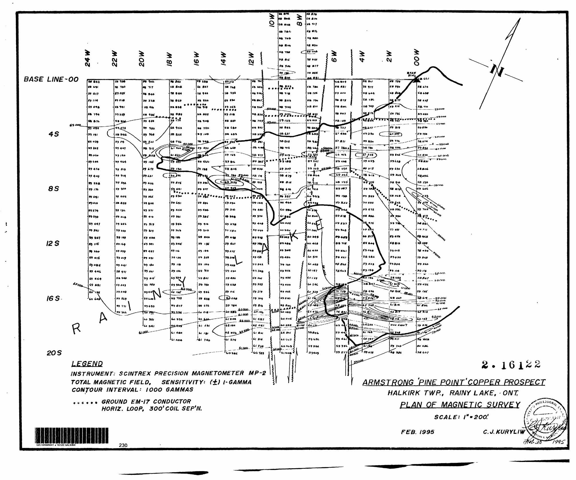
Contouring of the corrected and plotted magnetic readings was
carried at 1000 gamma intervals.
RESULTS OF MAGNETIC SURVEY
The magnetic survey over the Pine Point Grid is one of
relatively flat magnetic relief with the exception of the
gabbro-basic lava contact. The gabbro rises in magnetic
relief over 2000 gammas above the relatively flat relief of
the basic lava. There is a marked increase in the magnetic
relief on lines 2- W to 10 - W at about 16 - S on the grid.
There is an obvious shift in the gabbro contact of about 200
ft. northwards centered on 6- W and there is also an increase
of about 12.000 gammas in the gabbro near the fault. This
fault block shift is very useful in interpreting the
electromagnetic conductor extensions.
A second belt of slightly higher magnetic relief occurs in the
spherulitic rhyolite.
TOW
NSH
IP
HALK
IRK
WIN
D BA
Y ST
RING
ER
ZONE
SB- 3
9 Q
.03%
CU,
0.7
20XO
ZN /3
9.3m
in
elud
ts Q.
18%
CU,
3.6
9eX0
2N/
5.1m
SB-4
1 2m
mes
sivt
py
undt
rlain
by
20m
of
zinc
alttr
id O
P {0
.*0X
oZNJ
•PIN
E PO
INT
COPP
ER PRO
SPEC
T RAINY
LAKE
, ON
T.
PLAN
SHOWING. G
EOLOGY,
LINE.GRID,
INPU
T CO
NDUC
TOR ANOMALIES
\ *"
^NOTE t
THE
STRA
TIGR
APHI
C SEQUENCE S
HOWN
HERE
IS T
HE S
AME
AS OC
CURS
AT TH
E PORT A
RTHU
R CO
PPER
MIN
E,
1*0 Km
. 10
E-N
-EPINE
PO
INT
- W
IND
BAY
300m
^
• ••H
D5
SPPM
CO
NDUC
TOR
Q
* IN
PU
T A
NO
MA
LY
Q—
—^
PROP
OSED
HO
LE
:j|.'.
'.*:::
AL
TERA
TION
ZONE
20O
4Q
O
600
800
Quartz— eye Rhyolite
Zn— bearing Bedded Tuff Rhyolite with Stringer Sulfides
^ Htoafic Breccia— Vesicular*s.Rhyolite with Chlorite Seams
^
l Mafic Flow
Spherulitic Rhyolite
Chloritic and MineralizedIntermediate/MaficVolcanics
Gabbro
100 ft
STOP 3 - PORT ARTHUR COPPER
FROM 1991 M.N.R. FIELD TRIP (C. BLACKBURN)
Figure 7. Sketch map of geology at Port Arthur Copper Mine
105NOTE; THE STRATIGRAPHIC SEQUENCE SHOWN HERE IS THE SAME
AS OCCURS AT THE ARMSTRONG PINE POINT PROSPECT. bO Km. TO THE W-S-W
CHESTER J. KURYLIW. M.Sc-..CONSUI.TIMG CKOUIGIifT
16 INGALL Du. DRYJIKN. ONTARIO r** mi
LOCAL GEOLCGY ( con't)
* Stop 3; The Port Arthur Copper Mine
The open cnt was developed during the winter 1916-17 and later in 1917 a 30 m deep shaft with a first level drift 65 ra long were developed. In total, "several* carloads of ore grading 3 to S.5% Cu were shipped to Trail B.C.. The property was further developed by a shallow drill program in 1956 by Stratmat Ltd. and a complex distribution of copper and zinc has been interpreted from the results of that program (Fig. 3b and Poulsen, 1984). The recent stripping has been performed by Minnova Ltd., Thunder Bay who kindly provided the accompanying sketch (Pig. 7) as -a guide to the many features in the outcrop.
The southernmost exposure is that of a medium grained metadiabase that cuts the altered and mineralized zone. The overlying chloritized and sericitized intermediate to--maf.ic. amygdaloidal flows and breccias contain variable amounts of sphalerite, chalcopyrite and pyrite with quartz and iron carbonate' ' '^ evidenced by Jth'e^ variaBIe i intensity ' of rusty ' wea'tHer ing .
"Representative samples' of the mineralized materiaT may "stxlTT be found locally in the dump to the west. The mineralized zone is capped to the north by a narrow zone of banded silicified and sericitized rock with local pyrite seams. This is overlain, in turn, by successive spherulitic rhyolite flows and mafic amygdaloidal breccias with local vague pillow forms and which locally are cut by mafic dykes and quartz veins. Massive sulfides have been intersected in drilling at the top of the northernmost of the mafic units. This mafic unit is overlain by vesicular and amygdaloidal rhyolite containing stringer sulfide mineralization and capped by a 5 m thick sequence of carbonate- and sphalerite-bearing bedded tuffs or sediments. This unit appears to cap the hydrothermal alteration and mineralization in this area and is overlain by a substantial thickness of unaltered quartz-eye rhyolite.
* Prom Kenora ?fl.N.R. Pieldtrip (C. Blackburn)
Note, The Same Formation and Sequence of Members occurs at the Port Arthur Copper, as Mapped by Minnova at the Pine Point Copper prospect. (C.J.Kuryliw)
GEOP
HYSI
CAL/
OEOC
HEM
ICAl
. SEM
ESM
AP
f//
ATIK
OKA
N-M
INE
CENT
RE A
REA
"f (j
(W
ESTE
RN P
ART)
*
Alfb
orm
Ele
ctro
mag
netic
Sur
vey
lolu
l lul
oiis
lly M
'i||im
lh: S
uivi
jyO
WIM
IRI O
r IV
MNT
NV
IM
0.
INPU
T AN
OM
ALY
^^.^
^^a,
200
400
600
OOP
IKM
.XV
"S
aSS
glJ^
a.
ARM
STRO
NG P
INE
POIN
T CO
PPER
PRO
SPEC
T RA
INY
LAKE
.OBN
T.
- 8 -
INTRODUCTION
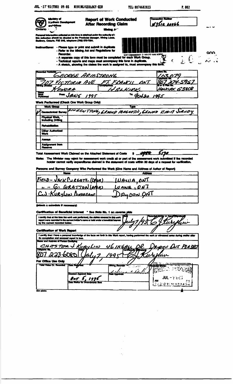
During the period of January 29 to February 06. 1995 Jack
Cureatz of Wawa, Ontario laid out the line grid and carried
out the instrument survey with assistant G. Gratton of Wawa,
Ontario. The plotting, draughting, interpretations and report
were done by this writer.
- 5 -
RESULTS OF MAGNETIC SURVEY CONTINUED;
Several local magnetic high anomalies occur spread out along
the southern contact of the spherulitic rhyolite and basic
lavas. Some of these magnetic high anomalies form "shoulders"
to E.M. conductors. This would be significant if the local
magnetic highs are caused by pyrrhotite with magnetite.
- 6 -
RECOMMENDATIONS
Several horizontal loop E.M. conductors were located with
suppoiting magnetic patterns These conductors should be
drilled to determine if base metal sulphides occur in these
conductors.
February 20. 1995 Chester J. Kuryliw
- 7 -
CONCLUSIONS
The magnetic survey was successful in tracing the formations
and it is immensely useful in recognizing and locating faults
that appear to be pre-sulphide mineralization in age.
February 20, 1995 Chester J. Kuryliw
CERTIFICATE
I, Chester J. Kuryliw of Jj-6 Ingall Drive, Dryden, Ontario, do hereby certify that:
(1) I am a Professional Engineer and I am currently employed as a Consulting Geologist for several mining companies.
(2) I am a graduate of:The University of Manitoba B.Se. Degree, 1949 The University of Manitoba M.Se. Degree, 1966
(3) I am a registered Engineer of the Association of Professional Engineers of Ontario and also Manitoba. I am a fellow of the Geologic Association of Canada, also a member of the Canadian Institute of Mining and Metallurgy.
(4) I have practiced a1.y profession for cv3r^5 years, most of thoseyears at gold mines, during which tiue l often planned, supervised2nd ~. ! recT'r'i 'jr.'!er~r''-"r. ;1 exclorati^Ti. devel . ^.Tient and oro^vrt. •L-'.T.
(5) My Report is based upon My personal field supervision of the Magnetic and Ele c tromagnetic surveys and upon my personal plotting and evaluation of results obtained.
Feb. 20, 1995Chester J. Kuryliw, M.Se., P.Eng.
JUL-27-95ITHU) 09:05 NINIHG/GEOLOGY-IEII TEL:I0746I2I23 P. 002
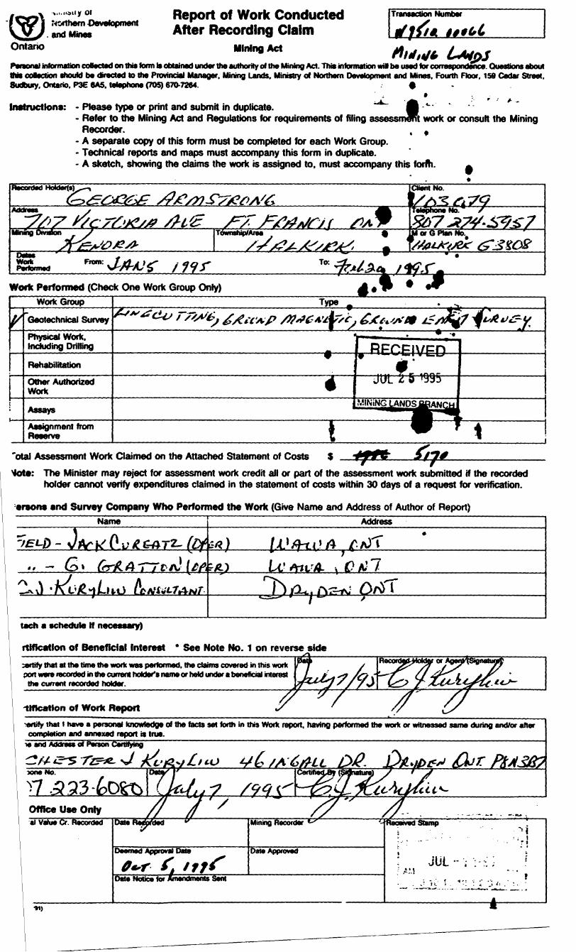
Itoport of Wortc Conducted After Recording Ctebn
Ontario f•ri
i typ* or print and won* bi dupttoaai Refer to ttw Mbring Aot md AoguMom forRocordw. . . ,. s?r.inNwno4i f -IBIT? HAI A MparaM copy of two form muatba compMBd foroach Work Group. Todhrricri rvportt and map* mwl atcompanyHiform In dupacahx ^ AtfMch, cnowlng th* dakMttio work b aailBnod lo. muat aooornpany Ms form.
""fa- onn
(Check Ono Worn Group Only)
mdudkiQ DMng
Total Ai aimed on the AtNokK The
MOfCoMi S l U or part of mo i
hoklar caimot warty axpendliiraa oWmad bi ma statement of coats wflhln 30 day* of a requaot tor
and Survey Company Who Parfotmad the Work (OK* Nama and Addraao of Aomor of Rapon)
h Mi Wo* npon. hntag pMtoimd A* verti or
•t.i.ndiiy OfNorthern-Oevetopmentand Mines
Ontario
Report of Work Conducted After Recording Claim
Mining Act
Transaction Number
tinPersonal information codected on this form Is obtained under the authority of the Mining Act. This information will be tised for correaporKJer^ffris coBection should be directed to the Provincial Manager. Mining Lands. Ministry of Northern Development and Mines. Fourth Floor, 150 Cedar Street.Sudbury. Ontario. P3E 6A5. telephone (705) 670-7264. .-f
--m V assessment
Instructions: - Please type or print and submit in duplicate.- Refer to the Mining Act and Regulations for requirements of filing
Recorder.- A separate copy of this form must be completed for each Work Group.- Technical reports and maps must accompany this form in duplicate.- A sketch, showing the claims the work is assigned to, must accompany this form.
work or consult the Mininge
Work Performed (Check One Work Group Only)WorkGroup Type
Geotechnical Survey
Physical Work. Including Drilling RECEIVEDRehabilitation
irttnrOther Authorized Work
AssaysAssignment from Reserve t
"otal Assessment Work Claimed on the Attached Statement of CostsMote: The Minister may reject for assessment work credit all or part of the assessment work submitted if the recorded
holder cannot verify expenditures claimed in the statement of costs within 30 days of a request for verification.
arsons and Survey Company Who Performed the Work (Give Name and Address of Author of Report)Name Address
Au" — S* 6r-X4T7"
v)
tach a schedule H necessary)
rtMcatlon of Beneficial Interest * See Note No. 1 on reverse side;ertify that at the time the work was performed, the claims covered in this work port were recorded in the current holder's name or held under a beneficial interest
the current recorded holder.
tlffcation of Work Report•*rtily that l have a personal knowledge of the facts set forth in this Work report, having performed the work or witnessed same during and/or after
completion and annexed report is true.ie and Address of Person Certifying
ftf' ifrt
Office Use Onlyai Vahie Cr. Recorded DateReArbed "
Deemed Approval Dale
0+r f f i?? f
Mining Recorder *-^ v-
Oate Approved
Date Notice for Amendments Sent
Deceived Stamp
-. ,- - -- - 'rt
i -
A911 *
N s lfe -^i!
CQ -^ S3
s )C 3
ci
V/i 10op4'
\
-.-**
V
^ o'
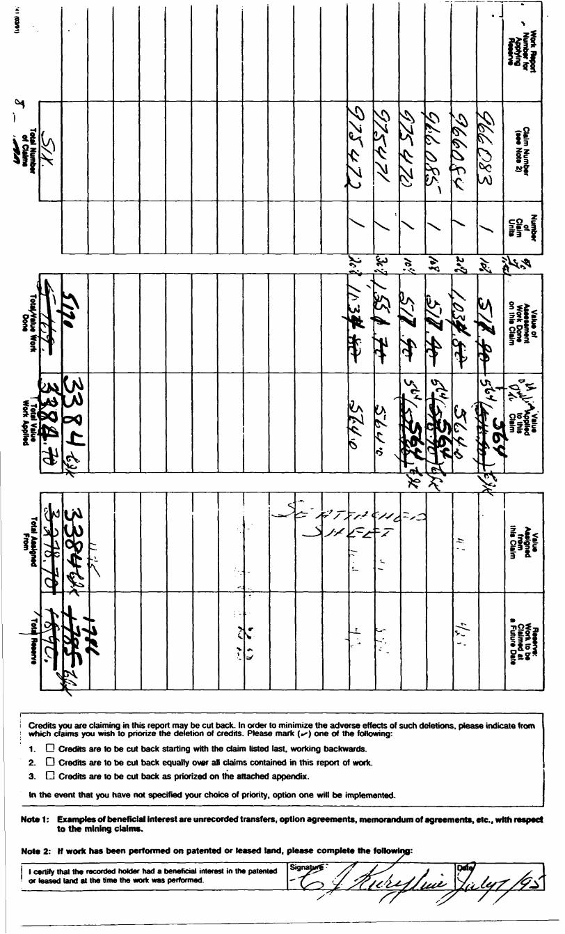
i Credits you are claiming in this report may be cut back. In order to minimize the adverse effects of such deletions, please indicate from i which claims you wish to priorize the deletion of credits. Please mark (^) one of the following:
1. G Credits are to be cut back starting with the claim listed last, working backwards.2. D Credits are to be cut back equally over an claims contained in this report of work.3. D Credits are to be cut back as priorized on the attached appendix.
In the event that you have not specified your choice of priority, option one will be implemented.
Note 1: Examples of beneficial interest are unrecorded transfers, option agreements, memorandum of agreements, etc., with respect to the mining claims.
Note 2: If work has been performed on patented or leased land, please complete the following:
l certify that the recorded holder had a beneficial interest in the patented or leased land at the time the work was performed.
Ontario
Miriist/y ofNortnem Developmentand Mines
Ministere du Deveioppement du Nord ei des mines
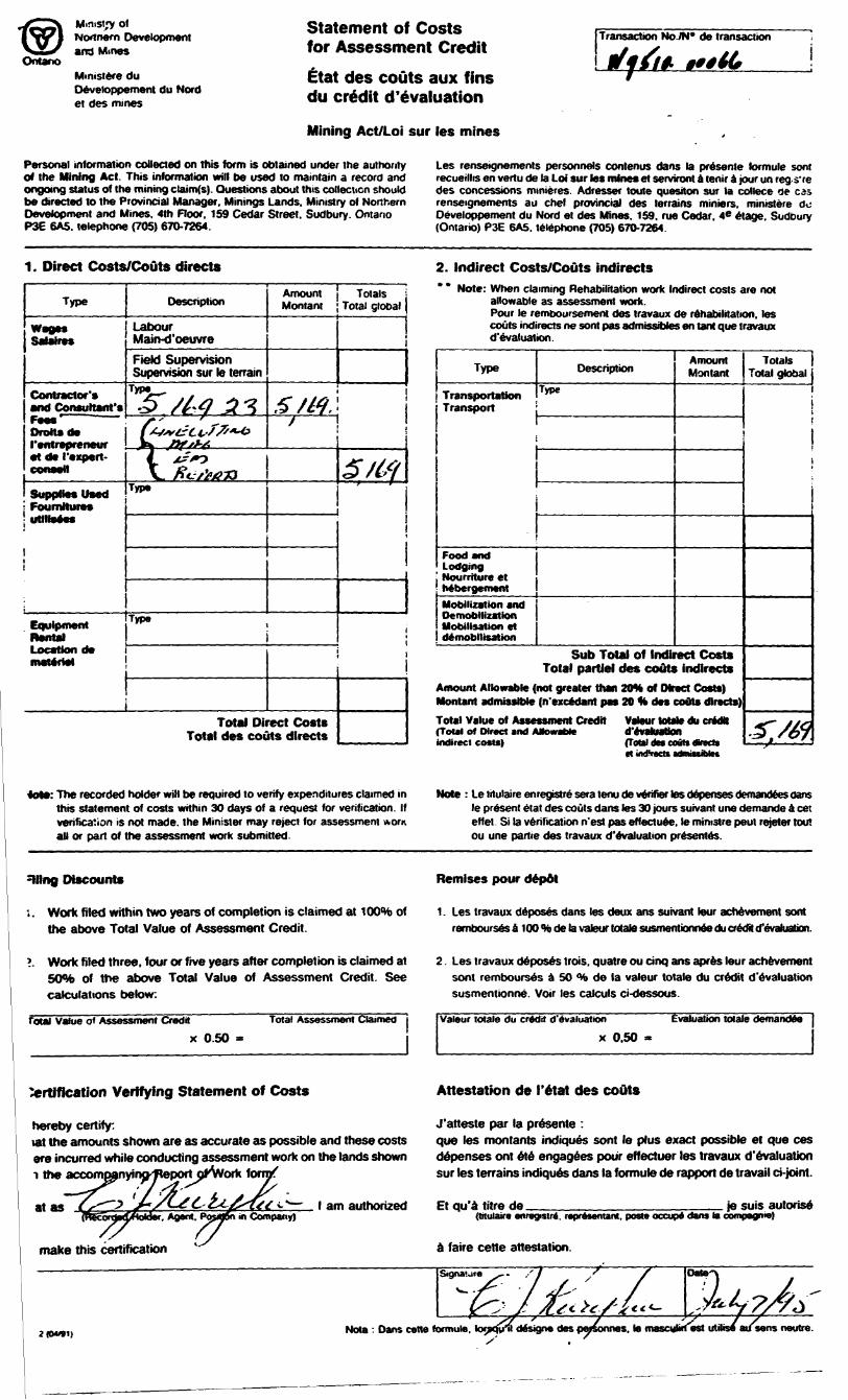
Statement of Costs for Assessment CreditEtat des couts aux fins du credit d'e valuation
Mining Act/Lot sur les mines
Transaction No IN' de transaction
Personal information collected on this form is obtained under the authority of the Mining Act. This information will be used to maintain a record and ongoing status of the mining ctaimfs). Questions about this collection should be directed to the Provincial Manager. Minings Lands. Ministry of Northern Development and Mines. 4th Floor, 159 Cedar Street. Sudbury. Ontario P3E 6A5. telephone (705) 670-7264.
Les renscignements personnels contenus dans la presenle formule sent recueillis en vertu de la Loi sur les mines ei serviront a tenir a jour un reg s're des concessions minieres. Adresser toute question sur la cdiece ae as renseignements au chef provincial des terrains miniers. ministere do Oeveioppement du Nord et des Mines. 159. rue Cedar. 4* etage. Sudbury (Ontario) P3E 6A5. telephone (705) 670-7264.
1. Direct Costs/Gouts directs
Type
Wag*. SaJaires
Contractor's and Consultant'sF***' Drafts de rentrepreneur•t d* Cexpert- conaell
Supplies used Foumitur**, -ftn m * — —uniwavs
Equipment Rental Location de materiel
Description
Labour Main-d'oeuvreField Supervision Supervision sur le terrain
Typ5~ ,3/64 31/•' 'l-tS*'t~t^//''*^fk S*f'*6T. 4?*?
\*. fit.-sfa73Type
Type
Amount Montant
S /M./
Total Direct Costs Total des couts directs
Totals Total global
i
3/6?
l l
2. Indirect Costs/Gouts indirects" * Note: When claiming Rehabilitation work Indirect costs are not
allowable as assessment work.Pour le remboursemeni des travaux de rehabilitation, les couts indirects ne sont pas admissibtes en tant que travaux d'evaluation
Type
Transportation Transport
Food and Lodging Nourriture et hebergementMobilization and Demobilization Mobilisation et demobilisation
Description
Type
-
Amount Montant
Sub Total of Indirect Costs Total partlel des couts indirects
Amount Allowable (not greater than 20* of Direct Costs) Montant admissible (n'excedant pas 20 H des couts directs)Total Value of ASM (Total of Direct and f indirect costs)
ssment Credit Valeur totale du credit utowaMe d'evakMtion
Totals Total global
i !
i
^./e)(t indVacts admistMes
tot*: The recorded holder will be required to verify expenditures claimed in this statement of costs within 30 days of a request for verification. If verification is not made, the Minister may reject for assessment worn all or part of the assessment work submitted.
Note : Le titulaire enregistre sera tenu de verifier tes depenses demandees dans le present etat des couts dans tes 30 jours suivant une demande A cet effet Si la verification n'est pas effectuee, le mimstre peut rejeter tout ou une partie des travaux d'evaluation presentes.
siting Discounts
i. Work filed within two years of completion is claimed at 10046 of the above Total Value of Assessment Credit.
Remises pour depot
1. Les travaux deposes dans les deux ans suivant tour achevement sont rembc^Jrsesa100%delav3leurtotalesusf^1ention^^ducreo^to"evahJatk)n.
?. Work filed three, four or five years after completion is claimed at 504fe of the above Total Value of Assessment Credit. See calculations below:
Total Value o* Assessment Credit Total Assessment Claimed
x 0.50
2. Les travaux deposes trois, quatre ou cinq ans apres lour achevement sont rembourses a 50 *to de la valour totale du credit devaluation susmentionne Voir les calculs ci-dessous.
Valour totale du credit devaluation
x 0.50Evaluation totale demandee
Certification Verifying Statement of Costs
hereby certify:tat the amounts shown are as accurate as possible and these costs ere incurred while conducting assessment work on the lands shown i the accompjnying^epprtpf'Vvork form/
tet^
make this certification
Agent. PofiOSn in Company)
Attestation de I'etat des couts
J'atteste par la presents :que les montants indiques sont le plus exact possible et que ces depenses ont ele engagees pour effectuer les travaux d'evaluation sur les terrains indiques dans la formule de rapport de travail ci-joint.
am authorized Et qu'a titre de je suis autorise(trtulaire enregislri. repntsentant. post* occup* dans la compagnie)
a faire cette attestation.
Signaiure
Nota : Dans cane formula. topoVil design* des pmsonnes. to masculirtest utilis/ ausens neotre.
OntarioMinistry ofNorthern Developmentand Mines
Ministere du Developpement du Nord et des Mines
Geoscience Approvals Section 933 Ramsey Lake Road 6th Floor Sudbury, Ontario P3E 6B5
Telephone: (705) 670-5853 Fax: (705) 670-5863
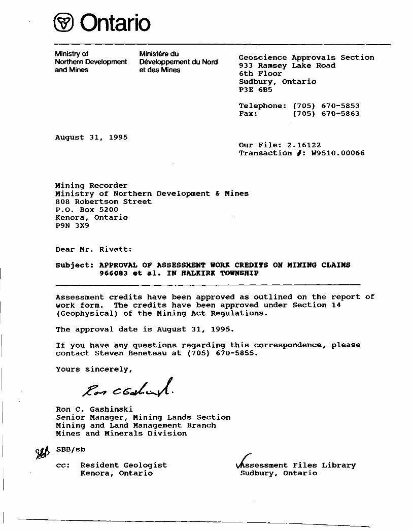
August 31, 1995Our File: 2.16122 Transaction f : W9510.00066
Mining RecorderMinistry of Northern Development808 Robertson StreetP.O. Box 5200Kenora, OntarioP9N 3X9
Mines
Dear Mr. Rivett:
Subject: APPROVAL OF ASSESSMENT WORK CREDITS ON MINING CLAIMS 966083 et al. IN HALKIRK TOWNSHIP
Assessment credits have been approved as outlined on the report of work form. The credits have been approved under Section 14 (Geophysical) of the Mining Act Regulations.
The approval date is August 31, 1995.
If you have any questions regarding this correspondence, please contact Steven Beneteau at (705) 670-5855.
Yours sincerely,
Ron C. GashinskiSenior Manager, Mining Lands Section Mining and Land Management Branch Mines and Minerals Division
SBB/sb
cc: Resident Geologist Kenora, Ontario
vAssssessment Files Library Sudbury, Ontario
________NOTES_______
400* surfoce rights reservation along tht shores of all lakes and rivers.
All Islands in Rainy Lake WITHDRAWN FROM STAKING under Sec.39 tub.(c) of Mining Act R.S.O. I960.
AREAS WITHDRAWN FROM DISPOSITIONMRO- Mining Right* Only
SRO- Surfoce Right* OnlyM * S -Mining and Surface Rights
Description Order NoC*j) 420*30 IMO)
5) PUBLIC HeSERVe
l 4SIMOI670) W 88/73
Date Disposition9*16/69 8RO
I98T S MO
6/12/79
RE-OKNRQ NW.R 14/84 T/I8/M
481*801670) W 44/71 ie/06/TB
WASTE DISPOSAL W B 9/S8 86/01/66
SAKMR
MO
6 MO.
File165474
165475
176403
7411 V 6
J6IMO I860) W 67/86 14/04/66 MtS
WD-KC-IO/91 NWR JULY 11/91 8RO
166666
OBIKOBA LAKE M.2126 PORTER INLET M.2459
Ntirottmtnl 9ut**y b* H A Smith
120489!)
MKO MRO 242276 l 14227*
™TiT
NORTH RANGE
———I.————
SOUTH RANGE 9147 j 939148 939143 l 732364
l l l—XZ—l———-,— tT l * TS?S6'~]"K 17-- j K
|"*' BI y 939180 j 939149 | 939.46 939 146 93*44
NORTH RANGE *yp im i95*183 |Bi0l82
r391841927866 |94r864
I^^P989 IBS 927867 1927566 ft 3766VSOUTH RANGE' SIS97 l 7*1398
J.- i .. — —' -T.~' —i~n~—~—r~s— —
1150058
a i n y
5OIP8
50127 i
Armot Id 5 s^*.
1178217
CO
CVJ*
s
BLISS
P 624
S? 5
A160
THE INFORMATION THAT APPEARS ON THIS MAP HAS BEEN COMPILED FROM VARIOUS SOURCES, AND ACCURACY IS NOT GUARANTEED THOSE WISHING TO STAKE MIN ING CLAIMS SHOULD CON SULT WITH THE MINING RECORDER, MINISTRY OF NORTHERN DEVELOP MENT AND MINES, FOR AD DITIONAL INFORMATION ON THE STATUS OF THE LANDS SHOWN HEREON
gf ACTIVE DATt
LEGEND
HIGHWAY AND ROUTE No
OTHER ROADS
TRAILSSURVEYED LINES.
TOWNSHIPS, BASE LINES, ETC LOTS. MINING CLAIMS, PARCELS, ETC
UNSURVEYED LINES LOT LINES PARCEL BOUNDARY MINING CLAIMS ETC
RAILWAY AND RIGHT OF WAY UTILITY LINES
NON-PERENNIAL STREAM FLOODING OR FLOODING RIGHTS
SUBDIVISION
ORIGINAL SHORELINE
MARSH OR MUSKEG
MINES
DISPOSITION OF CROWN LANDS
TYPJLPJ. DOCUMENT
PATENT SURFACE A MINING RIGHTS
SURFACE RIGHTS ONLY
MINING RIGHTS ONLY
LEASE, SURFACE A MINING RIGHTS SURFACE RIGHTS ONLY
MINING RIGHTS ONLY
LICENCE OF OCCUPATION
CROWN LAND SALE
ORDER-IN-COUNCIL
, RESERVATION
CANCELLEDSAND A GRAVEL
SYMBOL
B BV cs oc
(D
SCALE : 1 INCH 40 CHAINSaoo loop too 4000 eooo
FEET
METRESO tOO 4OO (00 100 l KM
ACRES HECTARES
TOWNSHIPS
HALKIRK FARRINGTONDISTRICT
RAINY RIVER
MINING DIVISIONKENORA
Ontario
Ministry of Natural ResourcesSurveys and Mapping Branch
Date APRIL 1970
Whitney Block Queen s Pork, Toronto
Plan No.
G-3808
62C10NW0041 2 18122 HALKIRK 200
PDCUT n a
BASE LINE-00
IMAGINARY (OUT-OF-PHASE)
REAL UN-PHASE) }
READINGS
INSTRUMENT* GEONICS E-M*I7
MODE.' HORIZ. LOOP
COIL SEPARATION: 3OO1&0
2. 16122
16 S
20 s
ARMSTRONG PINE POINT COPPER PROSPECTHALKIRK TWP.. RAINY LAKE, ONT.
PLAN OF ELECTROMAGNETIC SURVEY
l62C1QNWCKM1 2 16122 HALKIRK
SCALE: l"*200'
FEB. 1395 C. d KURVLIW210
i5*CM
i CM
ocvi
BASE LINE-00
4S
12 S
16 S
•12
-l
r\\
r*'
IX
t-*.
ri-i*
•r *i
•7
-S-
7l
-i
-2
}O
f
f'
V*2'J
*l 1
-S
\
-*
; /,ii i\'z\\l
ltjm\41
7*JCr:
v8 -*v\);Mr /^ -y
u'I **' y
^ *
-1 1y -*4 -'
S*"i 'far ifi **\0 4f
vr *v7f V
r7 "'\
/\ ** \ ' *':\ i
-31 .
y AJL. '\\
Y-9 '
7f'At
-t 'f
V**
\II'f\
7•-A*^^
i /
*\\\
"7 ^'
7•5 *\\
-ft
-lo
X-vx
f M
- !
(OUT-OF- PHASE)
T-/* /TV x' /' /w.
(IN-PHASE) t
N/riv
INSTRUMENT: GEONICd E-M-17
HORIZ. LOOP SURVEY
COIL SEPARATION- 30O'L V
ARMSTRONG PINE POINT COPPER PROSPECTHALKIRK TWP., RAINY LAKE, ONT.
PLAN OF ELECTROMAGNETIC SURVEY
SCALE: I"*2OO'
FEB. 1995 C. d62C10NW0041 2 '10122'HAkKIRK 220
BASE LINE-OO
690MZ
4S
8S
12 S
16 S
20 S
PLEGENDINSTRUMENT: SCINTREX PRECISION MAGNETOMETER MP-2TOTAL MAGNETIC FIELD, SENSITIVITY: (±) l-GAMMA CONTOUR INTERVAL; 1000 GAMMAS, . * , * . GROUND EM-17 CONDUCTOR
HORIZ. LOOP, 30O'COIL SEP'N.
ARMSTRONG 'PINE POINT'COPPER PROSPECT HALKIRK TWP., RAINY LAKE, OA/T
PLAN OF MAGNETIC SURVEY
SCALE: l"-200!
FEB. 1995 C.J.KURYLIW
s*** \ ^vBASE LINE-00 a
^i"^^^^3
165
2OS
62C10NWOM1 2 16122 HALKINK
INSTRUMENT: SCINTREX PRECISION MAGNETOMETER MP-2 TOTAL MAGNETIC FIELD, SENSITIVITY: (±) l- GAMMA
INTERVAL^ 1000 GAMMAS. . . . . GROUND EM-17 CONDUCTOR
HORIZ. LOOP, XOO'COIL SEP'N.
ARMSTRONG 'PINE POlNT'COPPER PROSPECT HALKIRK TWP., RAINY LAKE, - 0A/7T
PLAN OF MAGNETIC SURVEY
: l**200f
FfB. 1995 C.J.KURYLI240