
RPmag62 - Gesint S.r.l. · PDF fileRPmag62 825B092P Electromagnetic flowmeter Features •...
25
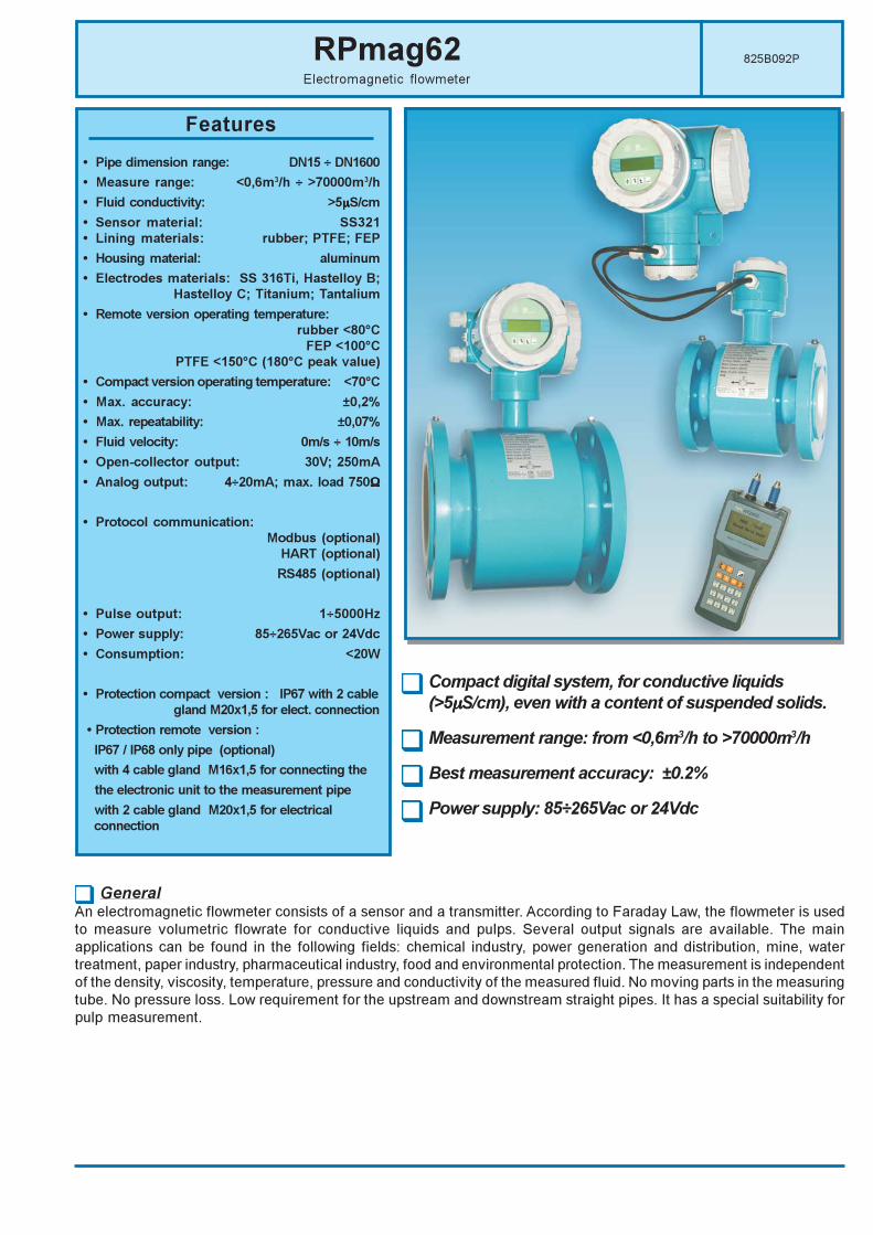
825B092P RPmag62 Electromagnetic flowmeter Features • Pipe dimension range: DN15 ÷ DN1600 • Measure range: <0,6m 3 /h ÷ >70000m 3 /h • Fluid conductivity: >5µS/cm • Sensor material: SS321 • Lining materials: rubber; PTFE; FEP • Housing material: aluminum • Electrodes materials: SS 316Ti, Hastelloy B; Hastelloy C; Titanium; Tantalium • Remote version operating temperature: rubber <80°C FEP <100°C PTFE <150°C (180°C peak value) • Compact version operating temperature: <70°C • Max. accuracy: ±0,2% • Max. repeatability: ±0,07% • Fluid velocity: 0m/s ÷ 10m/s • Open-collector output: 30V; 250mA • Analog output: 4÷20mA; max. load 750Ω • Protocol communication: Modbus (optional) HART (optional) RS485 (optional) • Pulse output: 1÷5000Hz • Power supply: 85÷265Vac or 24Vdc • Consumption: <20W • Protection compact version : IP67 with 2 cable gland M20x1,5 for elect. connection • Protection remote version : IP67 / IP68 only pipe (optional) with 4 cable gland M16x1,5 for connecting the the electronic unit to the measurement pipe with 2 cable gland M20x1,5 for electrical connection General An electromagnetic flowmeter consists of a sensor and a transmitter. According to Faraday Law, the flowmeter is used to measure volumetric flowrate for conductive liquids and pulps. Several output signals are available. The main applications can be found in the following fields: chemical industry, power generation and distribution, mine, water treatment, paper industry, pharmaceutical industry, food and environmental protection. The measurement is independent of the density, viscosity, temperature, pressure and conductivity of the measured fluid. No moving parts in the measuring tube. No pressure loss. Low requirement for the upstream and downstream straight pipes. It has a special suitability for pulp measurement. Compact digital system, for conductive liquids (>5 µ µ µ S/cm), even with a content of suspended solids. Measurement range: from <0,6m 3 /h to >70000m 3 /h Best measurement accuracy: ±0.2% Power supply: 85÷265Vac or 24Vdc
-
Upload
truongphuc -
Category
Documents
-
view
217 -
download
1
Transcript of RPmag62 - Gesint S.r.l. · PDF fileRPmag62 825B092P Electromagnetic flowmeter Features •...
825B092PRPmag62Electromagnetic flowmeter
Features
• Pipe dimension range: DN15 ÷ DN1600
• Measure range: <0,6m3/h ÷ >70000m3/h
• Fluid conductivity: >5µµµµµS/cm
• Sensor material: SS321
• Lining materials: rubber; PTFE; FEP
• Housing material: aluminum
• Electrodes materials: SS 316Ti, Hastelloy B;
Hastelloy C; Titanium; Tantalium
• Remote version operating temperature:
rubber <80°C
FEP <100°C
PTFE <150°C (180°C peak value)
• Compact version operating temperature: <70°C
• Max. accuracy: ±0,2%
• Max. repeatability: ±0,07%
• Fluid velocity: 0m/s ÷ 10m/s
• Open-collector output: 30V; 250mA
• Analog output: 4÷20mA; max. load 750ΩΩΩΩΩ
• Protocol communication:
Modbus (optional)
HART (optional)
RS485 (optional)
• Pulse output: 1÷5000Hz
• Power supply: 85÷265Vac or 24Vdc
• Consumption: <20W
• Protection compact version : IP67 with 2 cable
gland M20x1,5 for elect. connection
• Protection remote version :
IP67 / IP68 only pipe (optional)
with 4 cable gland M16x1,5 for connecting the
the electronic unit to the measurement pipe
with 2 cable gland M20x1,5 for electrical
connection
GeneralAn electromagnetic flowmeter consists of a sensor and a transmitter. According to Faraday Law, the flowmeter is used
to measure volumetric flowrate for conductive liquids and pulps. Several output signals are available. The main
applications can be found in the following fields: chemical industry, power generation and distribution, mine, water
treatment, paper industry, pharmaceutical industry, food and environmental protection. The measurement is independent
of the density, viscosity, temperature, pressure and conductivity of the measured fluid. No moving parts in the measuring
tube. No pressure loss. Low requirement for the upstream and downstream straight pipes. It has a special suitability for
pulp measurement.
Compact digital system, for conductive liquids
(>5µµµµµS/cm), even with a content of suspended solids.
Measurement range: from <0,6m3/h to >70000m3/h
Best measurement accuracy: ±0.2%
Power supply: 85÷265Vac or 24Vdc

Page 2 of 26
RPmag62 - Features
1. FEATURES
1.1 Application condition
Ambient temperature: -25°C ÷ +55°C;
Relative humidity: 5%÷90%;
Ambient pressure: 86÷106kPa.
1.2 Process condition
Fluid conductivity: >5µS/cm;
Pressure: 4.0MPa (DN15÷DN150)
1.6MPa (DN100÷DN150)
1.0MPa (DN200÷DN1000)
0.6MPa (DN1200÷DN1600)
Operating temperature:
remote version: < 80°C, Rubber lining
< 100°C, FEP
< 150°C, max. 180°C (not continuous), PTFE lining
compact version: < 70°C
Power supply: 85÷265Vac or 24Vdc
1.3 Electrode continuous self-cleaning for electromagnetic flowmeters
When electromagnetic flowmeters have been working for long time, especially for the measurement of sewage , the
electrodes and internal wall of pipes are easily covered by deposits.
When the conductance of the deposit is different from the one of the measured medium , it makes error for measurement.
RPmag62 electromagnetic flowmeters use electrochemistry way to clean electrodes.
The working principle is : a small voltage is given between the electrodes and the measured medium , so that the
electrodes is negative and the measured medium is positive. Majority sewage has charge and iones negatives.
The electrodes with negative voltage can avoid to be covered by deposit and to remain clean
The above way can clean automatically and continuously the electrodes.
2. TECHNICAL DATA
2.1 Sensor
Pipe DN: 15, 25, 32, 40, 50, 65, 80, 100, 125, 150, 200, 250, 300, 350, 400, 450, 500, 600, 700, 800, 900, 1000, 1200, 1400, 1600
Velocity range: 0m/s÷10m/s
Accuracy: ±0.5%, of the measured value ( ±0.2% o ±0.3% optional)
Measuring tube material: stainless steel AISI321
Lining material: rubber, PTFE, FEP
Electrodes material: stainless steel SS 316TI, Hastelloy B, Hastelloy C, Titanium, Tantalum
Connecting flange material: carbon steel
Housing protection: IP67 or IP68 (only pipe for remote versions )
IP67 (compact version)
2.2 Transmitter
It is a microprocessor-controlled transmitter. It displays measured values and messages in both Italian , English ,
French and Spanich. There are two versions: remote and compact.
2.2.1 Special feature
• The magnetic field excitation is a programmable rectangular wave with low frequency. It increases the stability of
flow measurement and has low consumption.
• It uses a 16-bit microprocessor, fast processing and high accuracy.
• All digital processing, high disturbing resistance, reliable measurement, high accuracy, wide measuring range.
• Switching power supply is suitable for the wide changing range of voltage, EMC according to CE requirements.

Page 3 of 26
RPmag62 - Features
• Operating menu in Italian , English Franch and Spanishis easy to operate.
• Back lighted LCD display with high definition.
• Dual direction measurement function. It can display forward direction flowrate and reverse direction flowrate. Three
inside counters can respectively display forward direction volume, reverse direction volume and the different
volume of both directions. Optionally it is possible to communicate via RS485 using MODBUS protocol.
• Big range of constant coil current for sensor can fit different type sensor of electromagnetic flowmeter.
• Multifunction intelligent transmitter has self-test and self-diagnosis function.
• EEPROM can save the setting and the counters when power off.
• Remote version and compact version.
2.3 Technical data
2.3.1 Process condition
Ambient temperature: -25÷+55°C
Relative humidity: 5%÷90%
Power supply: 85÷265Vac or 24Vdc
Consumption: less than 20W
2.3.2 Accuracy
±0,5% of the measured value , ( ±0,2%, ±0,3% optional)
2.3.3 Repeatability
0,17% of the measured value for accuracy , ±0,5% ( 0,07% for accuracy ±0,2% ; 0,1% for accuracy ±0,3%)
2.3.4 Analog outout
Current output: 4÷20mA
Load resistance: 0÷750ohm for 4÷20mA
Basic error: measured value plus basic error ±10µA
2.3.5 Frequency and pulse output ( F / P+)
Frequency: For forward direction and reverse direction, the maximum frequency can be set between 1÷5000Hz.
The output is an open collector transistor with galvanic isolation. External power supply should be less
than 30V, and maximum current for the collector is 250mA when it works.
Pulse: For forward and reverse direction. The pulses can be up to 15000 per second. The pulse width is up to
25ms. The output is an open collector transistor with galvanic isolation. External power supply should be
less than 30V, and maximum current for the collector is 250mA when it works. Via an inside pull-up
resister, frequency and pulse output can use the 24V power supply. The maximum current for the
collector is 2.3mA when it works.
2.3.6 Display
Display with Italian, English, French and Spanish , five characters for flowrate and ten characters for volume.
2.3.7 Alarms ( FC-A / FC - B )
Two alarms are the open collector transistor output with galvanic isolation. External power supply should be less
than 30V, and maximum current for the collector is 250mA when it works.
2.3.8 Digital output
Communication serial output with RS485. It has protection against a lightning strike.
2.3.9 Damping
2÷100s (90%)
2.3.10 Isolation
The isolating voltage is more than 500V between analog output, pulse (frequency output), alarm and ground.

Page 4 of 26
sooldaoL 005NDot3NDmorfegnarwolF
)dradnats.nim51ND(
0002NDot006NDmorfegnarwolF
)dradnats.nim0061ND(
3. FLOW TABLES
RPmag62 - Features
Page 5 of 26
RPmag62 - Features
4. FUNCTION
4.1 Measuring principle
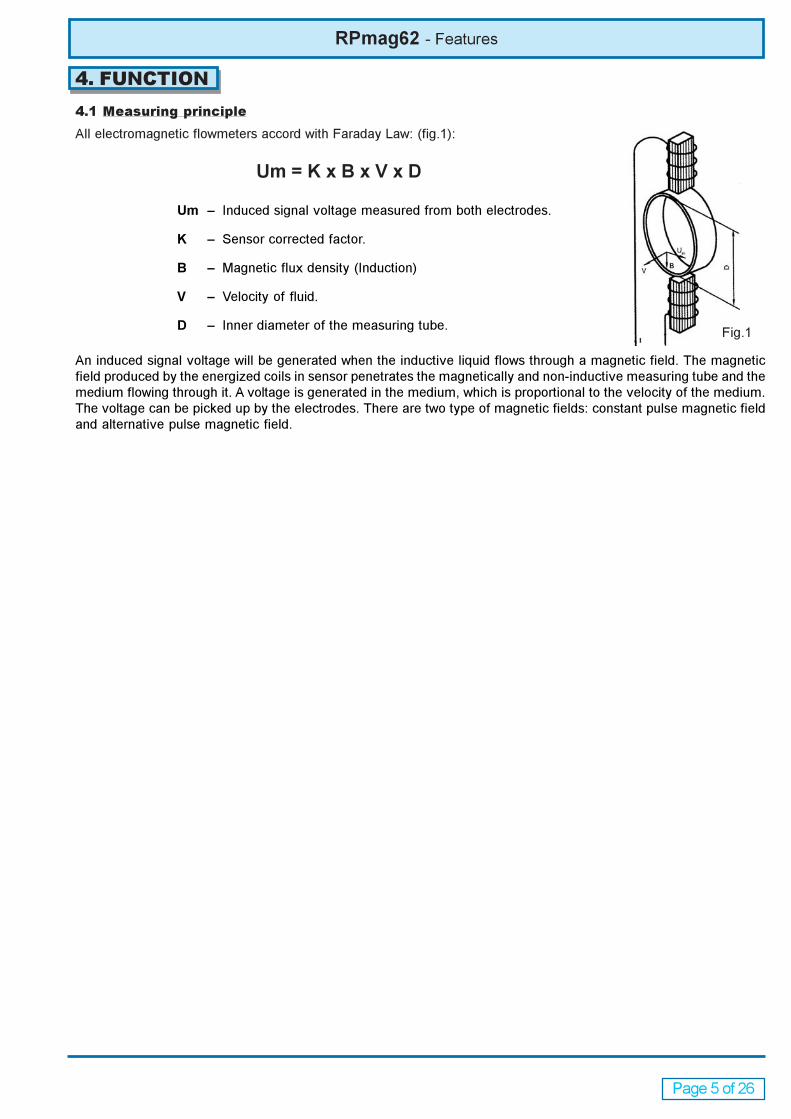
All electromagnetic flowmeters accord with Faraday Law: (fig.1):
Um = K x B x V x D
Um – Induced signal voltage measured from both electrodes.
K – Sensor corrected factor.
B – Magnetic flux density (Induction)
V – Velocity of fluid.
D – Inner diameter of the measuring tube.
An induced signal voltage will be generated when the inductive liquid flows through a magnetic field. The magnetic
field produced by the energized coils in sensor penetrates the magnetically and non-inductive measuring tube and the
medium flowing through it. A voltage is generated in the medium, which is proportional to the velocity of the medium.
The voltage can be picked up by the electrodes. There are two type of magnetic fields: constant pulse magnetic field
and alternative pulse magnetic field.
Fig.1
Page 6 of 26
RPmag62 - Features
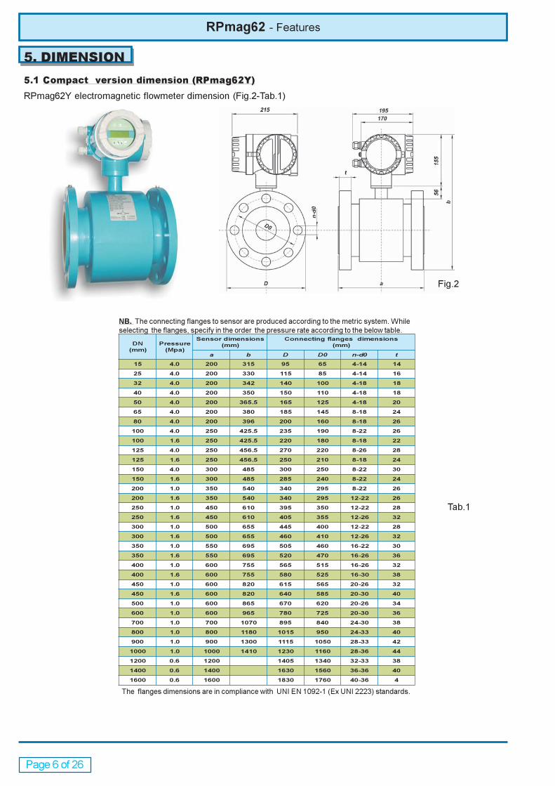
5. DIMENSION
5.1 Compact version dimension (RPmag62Y)
RPmag62Y electromagnetic flowmeter dimension (Fig.2-Tab.1)
ND
)mm(
erusserP
)apM(
snoisnemidrosneS
)mm(
snoisnemidsegnalfgnitcennoC
)mm(
a b D D0 d-n 0 t
51 0.4 002 513 59 56 41-4 41
52 0.4 002 033 511 58 41-4 61
23 0.4 002 243 041 001 81-4 81
04 0.4 002 053 051 011 81-4 81
05 0.4 002 5.563 561 521 81-4 02
56 0.4 002 083 581 541 81-8 42
08 0.4 002 693 002 061 81-8 62
001 0.4 052 5.524 532 091 22-8 62
001 6.1 052 5.524 022 081 81-8 22
521 0.4 052 5.654 072 022 62-8 82
521 6.1 052 5.654 052 012 81-8 42
051 0.4 003 584 003 052 22-8 03
051 6.1 003 584 582 042 22-8 42
002 0.1 053 045 043 592 22-8 62
002 6.1 053 045 043 592 22-21 62
052 0.1 054 016 593 053 22-21 82
052 6.1 054 016 504 553 62-21 23
003 0.1 005 556 544 004 22-21 82
003 6.1 005 556 064 014 62-21 23
053 0.1 055 596 505 064 22-61 03
053 6.1 055 596 025 074 62-61 63
004 0.1 006 557 565 515 62-61 23
004 6.1 006 557 085 525 03-61 83
054 0.1 006 028 516 565 62-02 23
054 6.1 006 028 046 585 03-02 04
005 0.1 006 568 076 026 62-02 43
006 0.1 006 569 087 527 03-02 63
007 0.1 007 0701 598 048 03-42 83
008 0.1 008 0811 5101 059 33-42 04
009 0.1 009 0031 5111 0501 33-82 24
0001 0.1 0001 0141 0321 0611 63-82 44
0021 6.0 0021 5041 0431 33-23 83
0041 6.0 0041 0361 0651 63-63 04
0061 6.0 0061 0381 0671 63-04 4
Fig.2
Tab.1
NB. The connecting flanges to sensor are produced according to the metric system. While
selecting the flanges, specify in the order the pressure rate according to the below table.
The flanges dimensions are in compliance with UNI EN 1092-1 (Ex UNI 2223) standards.
Page 7 of 26
RPmag62 - Features
ND
)mm(
erusserP
)apM(
snoisnemidrosneS
)mm(
snoisnemidsegnalfgnitcennoC
)mm(
a b D D0 d-n 0 1D
51 0.4 002 912 59 56 41-4 41
52 0.4 002 432 511 58 41-4 61
23 0.4 002 642 041 001 81-4 61
04 0.4 002 452 051 011 81-4 81
05 0.4 002 5.962 561 521 81-4 02
56 0.4 002 482 581 541 81-8 42
08 0.4 002 003 002 061 81-8 62
001 0.4 052 5.923 532 091 22-8 62
001 6.1 052 5.923 022 081 81-8 22
521 0.4 052 5.063 072 022 62-8 82
521 6.1 052 5.063 062 012 81-8 42
051 0.4 003 983 003 052 22-8 03
051 6.1 003 983 582 042 22-8 42
002 0.1 053 054 043 592 22-8 62
002 6.1 053 054 043 592 22-21 62
052 0.1 054 025 593 053 22-21 82
052 6.1 054 025 504 553 62-21 23
003 0.1 005 565 544 004 22-61 82
003 6.1 005 565 064 014 62-61 23
053 0.1 055 506 505 064 22-61 03
053 6.1 055 506 025 074 62-61 63
004 0.1 006 566 565 515 62-61 23
004 6.1 006 566 085 525 03-61 83
054 0.1 006 037 516 565 62-02 23
054 6.1 006 037 046 585 03-02 04
005 0.1 006 577 076 026 62-02 43
006 0.1 006 578 087 527 03-02 63
007 0.1 007 089 598 048 03-42 83
008 0.1 008 0901 5101 059 33-42 04
009 0.1 009 0121 5111 0501 33-82 24
0001 0.1 0001 0231 0321 0611 63-82 44
0021 6.0 0021 5041 0431 33-23 83
0041 6.0 0041 0361 0651 63-63 04
0061 6.0 0061 0381 0671 63-04 44
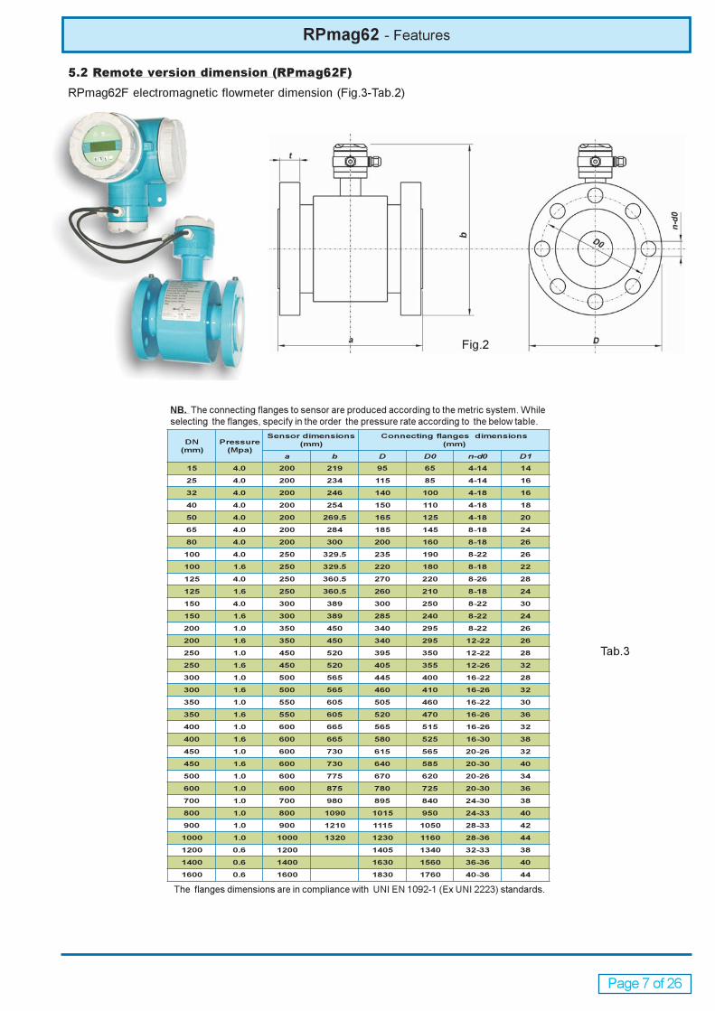
Fig.2
Tab.3
5.2 Remote version dimension (RPmag62F)
RPmag62F electromagnetic flowmeter dimension (Fig.3-Tab.2)
NB. The connecting flanges to sensor are produced according to the metric system. While
selecting the flanges, specify in the order the pressure rate according to the below table.
The flanges dimensions are in compliance with UNI EN 1092-1 (Ex UNI 2223) standards.

Page 8 of 26
RPmag62 - Installation
6. INSTALLATION
The design, test and power supply for flowmeters all have their safe rules. You must observe strictly the relative items
in this operating instruction to ensure the safety of the operation and application for flowmeters.
6.1 Safety measure
In order to ensure the safety of person and equipment, it must be observed as follows:
a) You should compare the details in the operating instruction and think over the environment requirement for the
flowmeter, before both selecting the installing position and installing the flowmeter.
b) The persons for installation and repair should be trained professionally.
c) Correctly install the sensor and accessories of the flowmeter, ensure the leakage. The operating pressure of medium
must not exceed the maximum operating pressure marked on the nameplate of the flowmeter.
d) Take some measure to prevent from electric shock.
e) The lift machine should reach the requirement of the relative safety rules.
6.2 Check before installation
a) Check the flanges, lining, housing and cable gland.
b) Open the lid of the connecting box to check the cable connection and PCB board if they are flexible or damaged.
c) Check if the type on the nameplate is same as the order data in the contract.
6.3 Lift
The flowmeter can be lifted using the lift as shown in Figure 5. The safe load and measure for the lift should reach to the
relative requirement. Don’t lift the flowmeter using the rope to tie the connection between the sensor and the transmitter
(compact version) or the connecting box (remote version).
Figure 5.
6.4 Installation of sensor
The flowmeter can test automatically flow direction. Because the direction arrow marked on the nameplate is flow
direction when calibration in factory, you should install the flowmeter to make the actual flow direction is same as the
flow direction arrow marked on the nameplate.
The upstream straight pipe should be longer than 5 × DN to guarantee the accuracy of measurement. When the
distance is more than 5×DN between the device (e.g. Cone tube, orifice plate, valve) and the sensor of flowmeter, their
affection is negligible. And the downstream straight pipe should be more than 3×DN.

Page 9 of 26
Figure 6. Installation in horizontal or vertical pipeline
Figure 7. Requirement for straight pipes to install the flowmeter
Figure 8. Installation in a constantly filled pipe
6.5 Installation in pipeline
In principle, the measurement of the electromagnetic flowmeter is independence of the distribution of velocity as long
as the distribution of velocity in measuring tube is symmetrical.
Installation may be horizontal or vertical, but make sure no deposit on the electrodes when horizontal installation. See
Figure 6.
RPmag62 - Installation
It is necessary to install an rectifier or straight pipe to normalize the flow profile if there are pipe elbow, flow regulation
valve or half-open ball valve in front of the sensor. See figure 7.
The electromagnetic flowmeter must be installed in the pipe fully filled with medium. The flowmeter must be installed
in the culvert with siphon phenomena in the case of an unfilled pipe. See figure 8.

Page 10 of 26
RPmag62 - Installation
The electromagnetic flowmeter should not be installed in the pipe section with a free pipe outlet that could run empty.
When installation in a downstream pipe, please make sure the pipe is always fully filled with medium. See figure 9.
Figure 9. Installation in pipe without emptying
The electromagnetic flowmeter should not be installed at the highest point of the pipe because of the accumulation of
gas. See figure 10.
Figure 10. Installation at highest pipe
Do not install the sensor on the intake side of a pump. This precaution is to avoid low pressure and the consequent risk
of damage to the lining of the measuring tube. See figure 11.
Figure 11. Near pumps installation

Page 11 of 26
Figure 14/A. Support
Install a siphon (fig. 12/a) with a vent valve (fig. 12/b) downstream of the sensor in down pipes longer than 5 meters.
This precaution is to avoid low pressure and the consequent risk of damage to the lining of the measuring tube. See
figure 12
Figure 12. Down pipe installation
6.6 Location of installation
The all-weather cover should be used to prevent the housing from the direct sunlight or rain when the device in the
open. The flowmerter should avoid the excessive vibration, high changing ambient temperature and long-time shower.
It should be prevent from the leakage of the corrosive liquid. The intensity of magnetic field should be less than 400A/M.
RPmag62 - Installation
6.7 Connection of pipes
The sensor itself can not be as its support, it should be supported to the connecting pipes. And the sensor should not
withstand too big fastening stress. It should be taken to account to eliminate the affection of the stress caused by
thermal expansion. See figeres 14/A/B
Figure 13. Location of installation

Page 12 of 26
RPmag62 - Installation
6.8 Mounting requirements
a) It should make sure the same axis between the measuring tube and operating pipe. For the sensors under DN50, The
axial difference between the measuring tube and operating pipe should be less than 1.5mm; for the sensors from
DN65 to DN300, it should be less than 2mm; for the sensor over DN350, it should be less than 4mm.
b) The gasket between flanges should have a good corrosive resistance. The gasket must not extend to the pipe inside.
c) The threads of he fasten bolts and nuts should be in good condition. The bolts should be fastened using torque
spanner with certain torque according the size of flange.
d) It should take separate measure to prevent the lining from heat when weld or flame cutting in the pipe closed to
sensor. If the sensor is installed in a well or immersed in the water, the connecting box for sensor must be filled and
sealed with sealing glue after commissioning.
6.9 Special rings
a) Grounding ring
Material: AISI321
Thickness: 3mm
For the non-conductive pipe, the grounding rings should be installed between the flanges of sensor and pipe to make
the flowmeter and measured medium same potential.
b) Protective ring
If the measured medium is with solid, the protective rings should be installed in the entrance of sensor. The lip of
protective ring should extend into the sensor to reduce the abrasion of lining.
Figure 14/B. Support
Figure 15. Special rings
Page 13 of 26
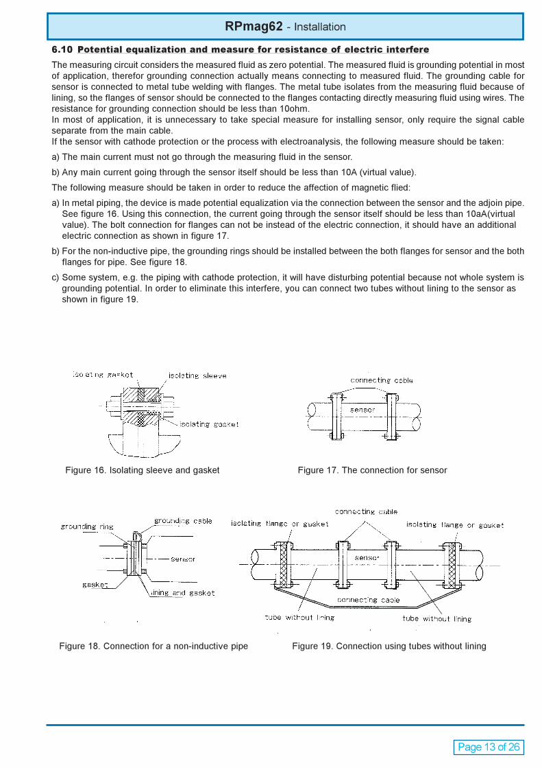
Figure 16. Isolating sleeve and gasket Figure 17. The connection for sensor
Figure 18. Connection for a non-inductive pipe Figure 19. Connection using tubes without lining
RPmag62 - Installation
6.10 Potential equalization and measure for resistance of electric interfere
The measuring circuit considers the measured fluid as zero potential. The measured fluid is grounding potential in most
of application, therefor grounding connection actually means connecting to measured fluid. The grounding cable for
sensor is connected to metal tube welding with flanges. The metal tube isolates from the measuring fluid because of
lining, so the flanges of sensor should be connected to the flanges contacting directly measuring fluid using wires. The
resistance for grounding connection should be less than 10ohm.
In most of application, it is unnecessary to take special measure for installing sensor, only require the signal cable
separate from the main cable.
If the sensor with cathode protection or the process with electroanalysis, the following measure should be taken:
a) The main current must not go through the measuring fluid in the sensor.
b) Any main current going through the sensor itself should be less than 10A (virtual value).
The following measure should be taken in order to reduce the affection of magnetic flied:
a) In metal piping, the device is made potential equalization via the connection between the sensor and the adjoin pipe.
See figure 16. Using this connection, the current going through the sensor itself should be less than 10aA(virtual
value). The bolt connection for flanges can not be instead of the electric connection, it should have an additional
electric connection as shown in figure 17.
b) For the non-inductive pipe, the grounding rings should be installed between the both flanges for sensor and the both
flanges for pipe. See figure 18.
c) Some system, e.g. the piping with cathode protection, it will have disturbing potential because not whole system is
grounding potential. In order to eliminate this interfere, you can connect two tubes without lining to the sensor as
shown in figure 19.

Page 14 of 26
RPmag62 - Installation
7. ELECTRIC CONNECTION
You should use the cable with circular section when electric connection for the seal of the cable glands.
7.1 Electric connection between sensor and transmitter
Electric connection between sensor and transmitter for the flowmeter with compact version has been finished before
the flowmeter leaves from factory. The content in this chapter is only for the flowmeter with remote version. See the
section “12” TRANSMITTER. If the location of installing sensor is in the water or easy to be immersed, the connection
box must be filled and sealed with silicon gel. It must be observed according to this operating instruction. For the
vertical installation, the electric connection and seal should be done before installation.
7.2 Electric connection for output and power supply
See the section “12” TRANSMITTER. You prepare the cables for output and power supply.
7.3 Requirement for electric connection
Switch off power supply before electric connection.
a) After checking the type of cables, please observe the instruction and regulation to connect cables correctly and
firmly.
b) When peeling the cable, please be careful not to damage the isolation that should be left. For the signal cable, the
shield for cable should be in good condition.
c) The cable length between sensor and transmitter is relative to the factors, such as the conductivity of fluid, electric
interfere and so on. The cable length can be simply evaluated as the following formula:
L= δ*4
Here, L is cable length, δ is conductivity of fluid (µs/cm).
However, the cable length should be less than 100m. In order to guarantee the measuring accuracy and reduce
interfere, please make close installation as possible between sensor and transmitter.
d) The type for the magnetic current cable and signal cable are two-core cable with braided shield which type is
RVVPX -3x1,0mm²
7.4 Terminal strips (remote version)
Connect cables to terminal strips as follows.
Figure 20.
roloceriW noitcnuFlanimreT
rebmun
eerF 41
poT
slanimret
seriw-owT
elbac
A500B525.doc
nworB 1.nlioC 14
kcalB 2.nlioC 24
seriw-eerhT
elbac
A400B525.doC
neerg-wolleY dnuorG 8
nworB 1.nedorttelE 6
mottoB
slanimret
etihW 2.nedorttelE 7
dleihsseriw-eerhT 4
dleihsseriw-owT 5
Tab.8

Page 15 of 26
8. COMMISSIONING
All above safe item and rules should be observed.
The follows should be checked before commissioning:
a) If there is any damage for the electromagnetic flowmeter during transfer and installation.
b) If the power supply is same as marked on the nameplate.
c) If the fuse is suitable.
d) If the flowmeter is potential equalization.
e) Use cables of circular section in order to guarantee the IP protection
f) Verify that the DIP-SWITCH related to the interface of connection for the external diagnostic unit are positioned on
"ON” as represented in the following drawing (Fig.22a)
RPmag62 - Installation
7.5 Remote version connection cables
The cables may use the PVC cables with braided shield which type is RVVPx2x1,0mm² and RVVPx3x1,0mm² or
similar
Figure 21
Fig. 22a
9. DIAGNOSTIC
You must read the safe item in each section before repair. Please contact the manufacturer after confirming the sensor
is fault.
9.1 Simple repair
Using eyes to check whether the electric connection is in good conditions and the meter can work or not.
9.2 Diagnosis
If the meter can not work well, you can check it as the follows:
a) Check if all valves in the piping are opened, if the pipe is filled fully with fluid, if the actual flow rate is close to the
upper limit of scale.
.
After above check, switch on the pipe valve to fill fully the piping. There should be no leakage and the gas in the piping
should be eliminated. Switch on the power supply for the flowmeter, the flowmeter can work well after warming up about
30 minutes.
Fig.22b
noitacinummoChctiwspiDfosutatS
321
tuohtiW
noitacinummocFFO FFO FFO
584SR FFO FFO FFO
TRAH FFO NO NO
SUB-DOM FFO FFO FFO
Fig.22c
g) Verify that the DIP-SWICH to three positions (Fig.22b) relative to the selection of communication is positioned as
represented in the following drawing (Fig.22c)

Page 16 of 26
RPmag62 - Installation
10. WHOLE SET
Whole set of meter consists of sensor and transmitter. For remote version, the standard cables length is 5m.
11. TRANSPORT AND STORAGE
In order to keep from damage during transport, the packing of the meter should be kept during storage.
The requirement of storage is as bellows:
a) Rainproof and dampproof, avoiding to be stroked.
b) The storage temperature is -20°÷ +60°C relative humility should be less than 80%, about 50% is better
c) Before the storage of the used sensor, the medium adhering on the lining and electrodes should be eliminated.
sisongaiD tluaF
epyT noitpircseD
oN
langis
tuptuo
tuptuo
setautciulf
elbatsnu
tnioporez
derusaem
fotuoeulav
ycarucca
tuptuo
sdeecxe
mumixam
etarwolf
dnagnipiP
evitaler
stnempiuqe
noitallatsnievitcefeD.1 x x x
epiplluftoN.2
sagniatnoC)1 x x
wolfgulprowolfelbbuB)2 x
rednusileveldiuqilehT)3
edortceleehtx
ropmupybdesuacesluP.3
evlavx x
diulF
sagniatnoC.1 x x
dilosniatnoC.2
naelctonsiedortcelE)1 x x
ehtrevoctisopeD)2
gninilroedortcelex x
mrofinutonsiytivitcudnoC.3
dlohserhtehtotesolcrox x
tonsistraptsewehT.4
diulfderusaemrofelbatiusx x
noitidnoC
dleifcitengamhgiH.1 x
gnipipmorftnerrucyartS.2 x
laitnetopdezilauqenU.3 x x
7.5 Table of diagnosis and analysis for electromagnetic lowmeters:
b) Check if the power supply, switch and fuse can work.
c) Check the fault is in the meter or in the cable.
d) Check if the number and sensor factor for the transmitter is same as the ones for the sensor.
e) Check if the setting of maximum flowrate is correct.
f) Check if the output connection is correct and the connection for potential equalization is in good condition.
g) Check the transmitter according to the relative items as shown in the section “12” TRANSMITTER
Page 17 of 26
RPmag62 - Electric connection
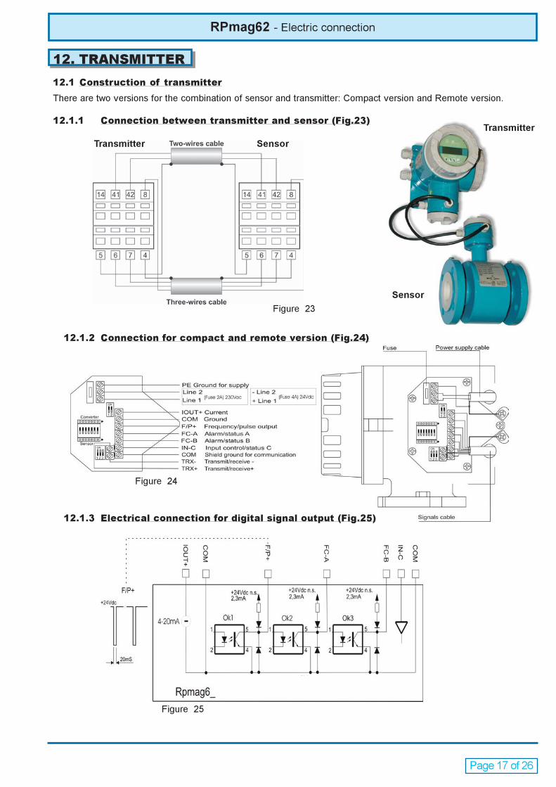
12.1.2 Connection for compact and remote version (Fig.24)
12. TRANSMITTER
12.1 Construction of transmitter
There are two versions for the combination of sensor and transmitter: Compact version and Remote version.
12.1.1 Connection between transmitter and sensor (Fig.23)
Figure 23
Transmitter Sensor
Transmitter
Sensor
12.1.3 Electrical connection for digital signal output (Fig.25)
Figure 25
Figure 24

Page 18 of 26
13.1 Key function
13.1.1 Key function in “RUN” mode
next page
last page
enter and exit
13.1.2 Key function in “SETTING” mode
The figure with cursor minuses 1(circularly)
The figure with cursor adds 1(circularly)
The cursor moves to left
The cursor moves to right;
Access to menu for setting parameters
Access to submenu, saving the parameters, exit and return to the measuring automatically mode (In
any case of being continuously pressed two seconds).
Figure 26
RPmag62 - Setting
13. SETTING
There are two operating modes with measuring automatically mode and parameter setting mode.
In measuring automatically mode, the flowmeter can carry out every measuring function and display the relative
measuring values. In parameter setting mode, you can use the four keys in the panel to set the corresponding parameters.
Note: In the parameter setting mode, the meter will automatically return to the measuring mode after 2
minutes of inactivity.
Page 19 of 26
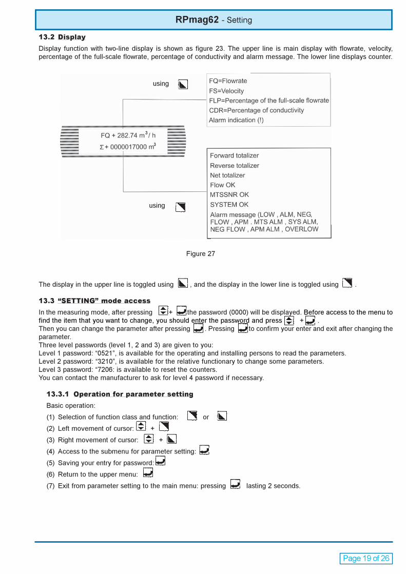
Figure 27
RPmag62 - Setting
13.2 Display
Display function with two-line display is shown as figure 23. The upper line is main display with flowrate, velocity,
percentage of the full-scale flowrate, percentage of conductivity and alarm message. The lower line displays counter.
The display in the upper line is toggled using , and the display in the lower line is toggled using .
13.3 “SETTING” mode access
In the measuring mode, after pressing + the password (0000) will be displayed. Before access to the menu to
find the item that you want to change, you should enter the password and press + .
Then you can change the parameter after pressing . Pressing to confirm your enter and exit after changing the
parameter.
Three level passwords (level 1, 2 and 3) are given to you:
Level 1 password: “0521”, is available for the operating and installing persons to read the parameters.
Level 2 password: “3210”, is available for the relative functionary to change some parameters.
Level 3 password: “7206: is available to reset the counters.
You can contact the manufacturer to ask for level 4 password if necessary.
13.3.1 Operation for parameter setting
Basic operation:
(1) Selection of function class and function: or
(2) Left movement of cursor: +
(3) Right movement of cursor: +
(4) Access to the submenu for parameter setting:
(5) Saving your entry for password:
(6) Return to the upper menu:
(7) Exit from parameter setting to the main menu: pressing lasting 2 seconds.
using
using

Page 20 of 26
RPmag62 - Setting
13.3.2 Menu of parameter setting
List for parameter setting menu for a glance:
metI noitpircseD gnitteS egnarretemaraPdrowssaP
level
1 EGSUGNAL tceleS,nailatI,gsilgnE
hsinapS,hcnerF2
2 SSERDDAMOC retnE 99÷0 2
3 ETARDUAB tceleS 00441÷006 2
4 LOCOTORPMOC tceleS,TRAH,584SR
SUBDOM2
5 EZISROSNES tceleS 0003÷3 2
6 EGNARWOLF retnE 99999÷0 2
7 SNPSRWOLF tceleS s001÷1 2
8 TCERIDWOLF retnE esrever,drawoF 2
9 OREZWOLF retnE s/mm000,0± 2
01 FFOTUCWOLF retnE %99÷0 2
11 ANEPSIDTUC tceleS elbasid/elbanE 2
21 TINULATOT tceleS ³m1÷L100.0 2
31 ANEN_AMGES tceleS elbasid/elbanE 2
41 EPYTGOLANA tceleS Am02÷4/Am01÷0 2
51 EPYTESLUP tceleS eslup/ycneuqerF 2
61 TINUESLUP retnE ³m1÷L 2
71 EULAVESLUP retnE ³m00,01÷L10,0 2
81 HTDIWESLUP retnE sm9991÷1,0 2
91 XAMNEUQERF tceleS zH0005÷1 2
02 ANEROSNESTM tceleS elbasid/elbanE 2
12 PIRTRSNSTM retnE %9,999 2
22 CRCROSNESTM retnE 999,3÷0000,0 2
32 TUOROSNESTEM retnE elbasid/elbanE 2
42 ANEHGIHMLA tceleS elbasid/elbanE 2
52 LAVHGIHMLA retnE %9,991÷,0 2
62 TUOHGIHMLA tceleS elbasid/elbanE 2
72 ANEWOLMLA tceleS elbasid/elbanE 2
82 LAVWOLMLA retnE %9,991÷,0 2
.muN noitpircseD gnitteS egnarretemaraPdrowssaP
level
92 TUOWOLMLA tceleS elbasid/elbanE 2
03 NEMLALATOT tceleS elbasid/elbanE 2
13 TUOLALATOT tceleS elbasid/elbanE 2
23 TSETNUFTUO tceleS%0,FFONOITCNUF
%001%57,%052
33 TCNUFSUTATS tceleS
MLAMETSYS,FFONOITCNUF
REWOP,WOLFEVITGEM
MRALAFILPMA,MRALA
2
43 NUFLRTCPNI tceleS
,LATOTRAELC,FFONOITCNUF
,NLATOTRLC,PLATOTRLC
DLOHWOLF,0=WOLF
53 LATOTRAELC drowssaP 999993÷000000 3
63 YEKLATOT retnE 999993÷000000 3
73 1EDOCROSNES gnittesyrotcaF etaD 4
83 2EDOCROSNES gnittesyrotcaF .oNnoitcudorP 4
93 TCAFROSNES gnittesyrotcaF 9999.3÷0000.0 4
04 EPYTDLEIF gnittesyrotcaF 4,3,2,1epyT 4
14 ROTCAFWOLF gnittesyrotcaF 9999.3÷0000.0 4
24 ROTCAFTLUM gnittesyrotcaF 9999.3÷0000.0 4
34 OREZGOLANA gnittesyrotcaF 9999.3÷0000.0 4
44 EGNARGOLANA gnittesyrotcaF 9999.3÷0000.0 4
54 ROTCAFRETEM gnittesyrotcaF 9999.3÷0000.0 4
64 1EDOCRETEM gnittesyrotcaF etaD 4
74 2EDOCRETEM gnittesyrotcaF .oNnoitcudorP 4
84 OLLATOTDWF dnameD 99999÷00000 4
94 IHLATOTDWF dnameD 99993÷00000 4
05 OLLATOTVER dnameD 99999÷00000 4
15 IHLATOTVER dnameD 99993÷0000 4
25 1DROWSSAP retnE 9999÷0000 2
35 2DROWSSAP retnE 9999÷0000 2
45 3DROWSSAP retnE 9999÷0000 3
55 4DROWSSAP retnE 9999÷0000 4
65 TESERPDAOL gnittesyrotcaF rerutcafunamrofylno

Page 21 of 26
RPmag62 - Setting
13.4 Parameters
13.4.1 LANGUAGE
With this function LANGUAGE, you can define the display language. It may be chosen between Italian , English,
French and Spanish
13.4.2 COM ADDRES
With this function COM ADDRES, you can set the identifying code for the flowmeter when the flowmeter communicate
with the master computer. It can be set from 0 to 99.
13.4.3 BAUD RATE
With this function BAUD RATE, you can select the baud rate for communicating with the master computer according
to the communicating ability of the master computer. You can select the baud rate from 600 bit/s ÷ 14400 bit/s.
13.4.4 COM PROTOCOL
COM PROTOCOL means the protocol type between the flowmeter and the relevant master. TYPE1 is the default
setting, normally it is direct protocol between the computer and the flowmeter. TYPE2 is the MOD-BUS protocol,
normally it is the protocol between the flowmeter and the PLC; DCS or other control system.
13.4.5 SENSOR SIZE
With this function SENSOR SIZE, you can select the nominal diameter of the flowmeter from 3÷3000m.
13.4.6 FLOW RANGE
FLOW RANGE means the full scale of flowrate. The upper limit is for output and the percentage display. It is relative
to the upper limit of output and frequency (pulse), 100% display value. It also is corresponding to flow cut off and
alarm over limit with percentage.
You can select the unit of flowrate with this function FLOW RANGE. According to the process and operating tradition
you can select a suitable unit of flowrate among l/s, l/min, l/h, m3/s, m3/min and m3/h.
Note: There are five efficient numbers to display the flowrate. After the last figure, the unit of flowrate is displayed.
If the selected unit is not suitable, the message “overflow” or “underflow” for the incorrect setting will display.
In this case that the efficient numbers couldn’t be displayed, you should select another unit.
13.4.7 FLOW RSPNS
Increasing flow response time can improve the stability for both flowrate display and output signal. You can select
one in the flowmeter.
13.4.8 FLOW DIRECT
If you consider the actual flow direction is forward and the display is reverse, you can select REVERSE; vice versa.
13.4.9 FLOW ZERO
When the pipe is full of standing fluid, the transmitter has corrected intelligently zero point. If the zero fluctuating
range is over the corrected ability, it is necessary that you correct the zero point. The zero point is indicated with
velocity in mm/s. The zero correction is shown as the following:
FS= 00000
± 0.000
In the display, the upper line indicates zero measuring value, the lower line indicates zero correction. When FS is not
0000, it should be corrected to zero.
Note: If FS increases when changing the correction value in the lower line, you should changeplus or minus in the
lower line to make FS equals zero.
Caution: Zero correction should be in the condition: The sensor is full of with standing fluid.
13.4.10 FLOW CUTOFF
Page 22 of 26
The value for flow cut off is stated as a percentage that relates to the upper range value of the flowrate. When the
flow cut off is enabled, the flowrate, velocity and percentage display are included.
13.4.11 CUT DISP ENA
You can select ENABLE or DISABLE. Only when you select “DISABLE”, it will display zero when the flowrate is under
the value in FLOW CUTOFF.
13.4.12 TOTAL UNIT
There is 10 characteristic numbers for counter in the transmitter. The maximum value for the counter is 4294967295.
The unit for counter is l and m3 with their multiples, such as 0.00001l, 0.0001l, 0.001l, 0.01l, 0.1l, 1l, 0.00001m3,
0.0001m3, 0.001m3, 0.01m3, 0.1m3, 1m3.
13.4.13 SEGMA N ENA
Enable or disable the possibility to measure the reverse direction flow and consequently also the differential measure.
13.4.14 ANALOG TYPE
You can select 0÷10mA or 4÷20mA for current output.
13.4.15 PULSE TYPE
There are frequency and pulse outputs for your selection in this function. Frequency output is continuous rectangle
wave. Pulse output is rectangle wave with gap. Frequency output is often used for digital flowrate measurement and
counter in short times. Pulse output is often used for counter in long times.
13.4.16 PULSE UNIT
You can select the relationship betweenpulses and measure units.
13.4.17 PULSE VALUE
PULSE VALUE means how many volumes per pulse. When the unit of flowrate is in l, the unit for pulse factor is in l-
1. When the unit of flowrate is in m3, the unit for pulse factor is in m-3. You can select one among 0.00001l-1, 0.0001l-1,
0.001l-1, 0.01l-1, 0.1l-1, 1l-1, 0.00001 m-3, 0.0001 m-3, 0.001 m-3, 0.01 m-3, 0.1 m-3, 1 m-3. At the same flowrate, pulse
factor is smaller and frequency of pulse output is higher. The maximum for pulse output is 5000 per second. For
mechanical counter, the maximum for pulse output is 25 per second. The maximum pulse width is 20ms. It will
change automatically to rectangle wave as high frequency.
13.4.18 PULSE WIDTH
You can select the pulse width
13.4.19 FREQUEN MAX
The maximum frequency is relative to the upper range of flowrate. You can enter the value from 1 to 5000HZ for
frequency.
13.4.20 MTSENSOR ENA
This function can detect empty pipe. If you select ENABLE in this function, analog output, digital output will be set to
zero and the value for flowrate will also display zero when the pipe is empty. If you select DISABLE, the meter will not
detect empty pipe.
13.4.21 MTSNSR TRIP
It regulates the threshold for detecting the empty pipe. If the percentage of conductivity CDR, displayed during
measure, grows up to the setted value, instrument will display an alarm. This CDR value grows up when the fluid
conductivity falls down, this means that pipe is emptying.
13.4.22 MTSENSOR CRC
It regulates range for detecting empty pipe and its sensibility and stability. Stability is given with less sensibility. It
regulates the percentage of conductivity CDR value displayed while pipe is empty.
13.4.23 MTSENSOR OUTIn menu 13.4.18, if you select “ENABLE” and the pipe is empty , LCD of the meter will display automatically the
information of “MTS ALM2 If you need alarm output , you should select “ENABLE” in this menu , the voltage of
terminal FC_A will become low level when the pipe is empty.
RPmag62 - Setting

Page 23 of 26
RPmag62 - Setting
13.4.24 ALM HIGH ENA
You can select ENABLE or DISABLE.
13.4.25 ALM HIGH VAL
The value of the upper limit alarm is a percentage that relatives the upper range of flowrate. You can enter one value
between 0% and 200%. When the flowmeter works, it will give an alarm output when the percentage of flowrate is
over this value.
13.4.26 ALM HIGH OUTIn menu 13.4.23 , if you select “ENABLE” , and the actual flowrate is more than the setting in the function ALM
HIGH VAL , LCD of the meter will display automatically the information of “HIGH ALARM”. If you need alarm
output , you should select “ENABLE” in this menu , the voltage of terminal FC-A will become low level when the
actual flowrate is more than the setting in the function ALM HIGH VAL.
13.4.27 ALM LOW ENAWhen you select “ENABLE” the meter will monitor if the flowrate is lower than the setting in the function ALM
LOW VAL , otherwise the meter well not do it.
13.4.28 ALM LOW VALIts definition is similar as ALM HIGH VAL.
13.4.29 ALM LOW OUTIn menu 13.4.25 , if select “ENABLE” and the actual flowrate is less than the setting in the function ALM LOW
VAL, LCD of the meter will display automatically the information of “LOW ALARM”. If you need alarm output , you
should select “ENABLE” in this menu , the voltage of terminal FC-A will become low level when the actual
flowrate is more than the setting in the function ALM LOW VAL.
13.4.30 TOTAL ALM ENWhen you select “ENABLE” the meter will monitor if the floward totalizer , reverse totalizer or net totalizer is more
than 999999990 , otherwise the meter will not do it.
13.4.31 TOTAL AL OUTIn menu 13.4.2 , when you select “ENABLE” , the meter will monitor if forward totalizer , reverse totalizer or net
totalizer is more than 999999990 , LCD of the meter will automatically display the information of “TOTAL FULL”
and stop count , and voltage of terminal FC_A will become low level . If you want to release this alarm , you need
to reset the totalizer (see 13.4.33)
13.4.32 OUT FUN TESTThis function is for test of analog output and frequency output.You can select 0%, 25% , 50% , 75% , or
100%.When 0% selected , analog output is 4mA and frequency output is 0Hz ; when 100% selected , analog
output is 20mA and frequency output is max frequency (see 12.4.17). When this function is enable , both analog
output and frequency output associate the relative values with the configuration and tey are indipendence of the
actual flowrate. This function will disable automatically when the meter works in measuring mode.
13.4.33 STATUSF UNCTWhen this function enables , the alarm will occur in the case that the system is abnormal.You can select which
kind of alarm you want.The alarm output is low level.Coil alarm (SYS ALM) occurs in the case of coil
problem.When the configuration of 13.4.18 is enable.Empty tube alarm (MTS ALM) occurs in the case of empty
tube.Other alarms are simila.If you don’t need the alarms ,you can close this function.
13.4.34 INP CLRL FUNThis function can be used to control the working status of the system via input from outside.You can configure
it.When CLR TOTAL is selected , net totalizer will be reset.When CLR TOT P is selected , forward totalizer will be
reset and net totalizer will be changed automatically. When CLR TOT N is selected , reverse totalizer will be reset
and net totalizer will be changed automatically.When FLOW=0 is selected , flow will be zero and analog output
will be 4mA and frequency output is 0Hz.When FLOW HOLD is selected , the display will be hold by the current

Page 24 of 26
value before this configuration , and output will be hold by the sane relative value.
13.4.35 CLEAR TOTALWith this function , three totalizers will be reset to zero and restart to count after password 3 is entered and
checked.
13.4.36 TOTAL KEY
It is for select password for resetting totalizers
13.4.37 SENSOR CODE 1
It records the date and code of production for making sure the sensor factor is correct.
13.4.38 SENSOR CODE 2
It records the order data for the flowmeter.
13.4.39 SENSOR FACTOR
Sensor factor is marked on the nameplate for the sensor. You should enter the sensor factor in this function.
13.4.40 FIELD TYPE
IThere are three modes for magnetic field excitation. You can select one according to the process condition. Normally
TYPE 1 is used. TYPE 2 and TYPE 3 is used for the measurement of clean water with big diameter.
Caution: The flowmeter should be calibrated under the same condition as the process condition.
13.4.41 FLOW FACTOR
It is a calculating factor available to be set. With this function, you can enter the density of medium so that the display
can be changed from volume to mass.
13.4.42 MULT FACTOR
It is a calculating factor available to be set. The measured value will multiply this factor to get the flowrate for the
calculation in the transmitter. E.g. the measurement for opened channel using the diving electromagnetic flowmeter
with simulating sensor.
13.4.43 ANALOG ZERO
With this function, you adjust the current output at zero flowrate (0mA or 4mA).
13.4.44 ANALOG RANGE
With this function, you adjust the current output at end flowrate range (10mA or 20mA).
13.4.45 METER FACTOR
This is a factor for consistency test of transmitter. It is set by manufacturer to guarantee the interchangeability of
transmitters for fitting the sensors.
13.4.46 METER CODE 1
It is identified code of the transmitter for manufacturer.
13.4.47 METER CODE 2
It is identified code of the transmitter for manufacturer.
13.4.48 FWD TOTAL LO
It is the low five figures for forward counter
13.4.49 FWD TOTAL HI
It is the high five figures for forward counter.
13.4.50 REV TOTAL LO
It is the low five figures for reverse counter.
RPmag62 - Setting

Page 25 of 26
RPmag62 - Setting
13.4.51 REV TOTAL HI
It is the high five figures for reverse counter.
13.4.52 PASSWORD 1
You can change this password 1 which level is 1. When shipping the device from factory, the password is 0521.
13.4.53 PASSWORD 2
You can change this password 2 which level is 2. When shipping the device from factory, the password is 3210.
13.4.54 PASSWORD 3
You can change this password 3 which level is 3. When shipping the device from factory, the password is 7206.
13.4.55 PASSWORD 4
You can ask the manufacturer for password 4 which level is 4. It can be changed.
13.4.56 LOAD PRESET
It is for loading the default parameters
GESINT®
GESINT S.R.L.Via Perosi, 520010 Bareggio (MI) - ITALYTel. 02/9014633 - 335/6282615Fax 02/90362295e-mail: info@gesintsrl. i t WWW.GESINTSRL.IT


![User's AXF Manual Magnetic Flowmeter Integral Flowmeter ... · User's Manual Yo kogawa Electric Corporation AXF Magnetic Flowmeter Integral Flowmeter/ Remote Flowtube [Hardware Edition]](https://static.fdocuments.us/doc/165x107/5c40f15893f3c338c3289cbb/users-axf-manual-magnetic-flowmeter-integral-flowmeter-users-manual-yo.jpg)


![User´s AXFA14G/C Manual Magnetic Flowmeter Remote ... · AXFA14G/C Magnetic Flowmeter Remote Converter [Hardware Edition/Software Edition] AXF Magnetic Flowmeter Integral Flowmeter](https://static.fdocuments.us/doc/165x107/5e9c29ae5a06915e2b2224e0/users-axfa14gc-manual-magnetic-flowmeter-remote-axfa14gc-magnetic-flowmeter.jpg)