RPM ROOFING - Best Materialsbestmaterials.com/PDF_Files/shakeinstall.pdf · RPM Roofing warranties...
19
R R R P P P M M M R R R O O O O O O F F F I I I N N N G G G Installation Guide Cedar Shake Distributed by: BEST MATERIALS LLC, Phoenx AZ 602-272-8128 800-474-7570 www.bestmaterials.com
Transcript of RPM ROOFING - Best Materialsbestmaterials.com/PDF_Files/shakeinstall.pdf · RPM Roofing warranties...

RRRPPPMMM RRROOOOOOFFFIIINNNGGG Installation Guide
Cedar Shake
Distributed by: BEST MATERIALS LLC, Phoenx AZ602-272-8128 800-474-7570 www.bestmaterials.com
Table of Contents
OVERVIEW ........................................................................................................... 1
CAUTION............................................................................................................. 1
DISCLAIMER ......................................................................................................... 1
PRODUCT SPECIFICATIONS........................................................................................ 2
GENERAL INFORMATION .......................................................................................... 3
PRODUCT DESCRIPTION ...............................................................................3 ACCESSORIES ............................................................................................3 NAIL REQUIREMENTS ...................................................................................4 UNDERLAYMENTS ........................................................................................4 METALS ....................................................................................................4 ROOF DECKING MATERIALS ..........................................................................5 ROOF PITCHES...........................................................................................5 ROOF VENTING..........................................................................................6 SPACING BETWEEN THE SHINGLES....................................................................6 COLD WEATHER INSTALLATION........................................................................6 STORING THE PRODUCT ................................................................................6 VENT FLASHINGS.........................................................................................6 SNOW GUARDS..........................................................................................6 ROOF CLEAN UP ........................................................................................6 NAILING PATTERN .......................................................................................7 BLENDING OF SHINGLES ...............................................................................7 LAYING OUT CUT SHINGLES............................................................................7 HIP & RIDGE .............................................................................................7 ROOF JUNCTURE DETAILS..............................................................................8
APPLICATION GUIDELINES ......................................................................................... 9
ROOF PREPARATION....................................................................................9 UNDERLAYMENT..........................................................................................9 LAYOUT ....................................................................................................9 VALLEYS..................................................................................................10 FLASHINGS ..............................................................................................11 ILLUSTRATIONS ..........................................................................................12 HIP & RIDGE DETAIL ..................................................................................17

Overview
1
The information provided in this manual is for a guideline and a suggested method to install roofing products manufactured by RPM Roofing. As with all roofing materials, acceptable and proven practices should be followed. All application procedures should be done in accordance with local building codes in your area. The information provided in this manual is strictly a guideline and does not imply responsibility for the final installation of the product. We assume no responsibility for methods of installation or the final results of such installation. RPM Roofing warranties its products for a 50 year period and applies to the product only and not the workmanship of the installed product. The roofing contractors should provide a separate warranty of their own. Material for this manual has been compiled from various authoritative and professional sources. Many of the methods described and shown herein are sound, time – proven guidelines and standards of good roofing practice that meet the requirements of national and local building codes throughout the U.S. Each geographic area may employ “area practices” that are also sound and time-proven, which by exclusion does not mean to imply that proven area practices are unsatisfactory.
Overview
Caution
The required spacing for adjacent shingles is a minimum of ½”. This will allow for expansion and contraction in various weather applications. This will also give a more natural aesthetic appearance of real shake. DO NOT install pieces that are damaged or lifted, as they will not lie down properly.
CCoolloorr BBlleennddiinngg For better color blending, we suggest you unload the simulated cedar shake from at least three (3) different pallets. This applies for both solid and blended colors.
Disclaimer
RPM Roofing Products are intentionally designed to imitate the natural appearance of actual roofing products. This manufacturing process contains a variation within all colors. Care should be exercised by the installer to mix this variation as randomly as possible.

Product Specifications
2
** These figures are based on a 48-foot flatbed trailer and may vary due to the amount of accessory pieces that may be shipped.
Shake – Class A Profile Cavity back Shake – Class C
Cavity back Exposure 10” 10”
Weight/Piece (lb.) 1.9 ± 0.2
1.2 (5”); 1.7 (7”); 2.8 (12”) 1.8 ± 0.2
1.1 (5”); 1.7 (7”); 2.8 (12”)
Pieces/Square 169 (total)
57 (5”); 56 (7”); 56 (12”) 169 (total)
57 (5”); 56 (7”); 56 (12”)
Lb./Square 322 304
Height 23” ± ⅛" 23” ± ⅛"
Width 5” ± ⅛"; 7” ± ⅛"; 12” ± ⅛" 5” ± ⅛"; 7” ± ⅛"; 12” ± ⅛"
Pieces/Bundle 15 (5 of each size) 15 (5 of each size)
Bundles/Square 11.27 11.27
Squares/Pallet 5.33 5.33
Pallets/Truck 24 24
Squares/Truck** 127 127
Fire Rating Class A Class C
Impact Rating Class 4 Class 4
Accessory Dimensions Pitch Weight (lb.) Pieces/Bundle Pieces/Pallet Lb./Pallet
Shake – Class A
Starter 14” Length 16” Width
2 10 780 1600
Hip & Ridge 14” Length
6” x 5-3/8” Width 5/12 – 7/12
2 10 240 500
Solid Shingle Accessory 23” ± ⅛" Length 12 ± ⅛" Width
4.5 10 480 2200
Shake – Class C
Starter 14” Length 16” Width
2 10 780 1600
Hip & Ridge 14” Length
6” x 5-3/8” Width 5/12 – 7/12
2 10 240 500
Solid Shingle Accessory 23” ± ⅛" Length 12 ± ⅛" Width
4.5 10 480 2200

General Information
3
No special tools required
• Cedar Shake shingles can be hand nailed or nailed with a pneumatic nail gun • Cedar Shake shingles can be cut with a standard skill, jig or table saw • The choice of open or solid sheathing is optional when simulated shake shingles are applied.
PPrroodduucctt DDeessccrriippttiioonn
The Simulated Cedar Shake is manufactured in three sizes. These sizes are all 23” ± ⅛" in length but vary in width. These widths are 5”, 7” and 12” ± ⅛".
AAcccceessssoorriieess
Starter Piece Weight 2.0 lb. Length 14” Width 16”
Preformed Hip/Ridge Shingle
Weight 2.0 lb. Length 14” Width 6” x 5-3/8”
Pitch 5/12 – 7/12
5 ⅛"
23” ± ⅛"
Exposure Line
Nail Mark
Texture
7 ⅛"
23” ± ⅛"
12 ⅛"
23” ± ⅛"
12” Special Solid Back Shingle (used for Valley cuts, Hip and Rake Edge)
Weight 4.5 lb. Length 23” ± ⅛" Width 12” ± ⅛"
General Information
4
NNaaiill RReeqquuiirreemmeennttss Cedar Shake Shingles
Cedar Shake shingles should be applied with two corrosion resistant fasteners, such as stainless-steel type (304 or 316), hot-dipped zinc coated, copper, aluminum or corrosion resistant pneumatic roofing nails with a 3/8” diameter head and 1 ½” in length. Nails should be long enough to penetrate the sheathing ½”.
Caution should always be used to insure against over/under penetration. In areas that experience high humidity or other severe climatic conditions, consideration should be given to using stainless steel fasteners and higher-grade accessories.
UUnnddeerrllaayymmeennttss Ice and Water Shield
• Single layer of 36 mil rubberized asphalt on 4 mil polyethylene carrier sheet • A 36" wide sheet in all valleys is recommended • 1 row of 36" wide along all eaves, lap end joints 6" and side joints 3" extended 3' inside the plate line • Apply around all dormers, roof projections, skylights, etc. • Always refer to your local building codes NOTE: Ice and water shield should not be installed over the felt. Felts • Asphalt saturated and coated organic felt base sheet which meets requirements of ASTM D2626 • Referred to a 30 LB. felt and without perforations • Secured with 3/4" long galvanized roofing nails
NOTE: Minimum requirement on a solid deck is one layer of 30 LB.
MMeettaallss
Valleys
• Minimum recommendations
o 16 oz. Copper o 26 ga. Corrosion resistant metal
Stainless Steel Color Clad Steel Color Clad Aluminum
o Eave Drip Starter Strips o Gable Edge Strips

General Information
5
RRooooff DDeecckkiinngg MMaatteerriiaallss
Solid Deck
• Minimum of 15/32" CDX plywood deck or equal
• Minimum 1" tongue and groove wood decking
Spaced Sheathing
• Usually 1 x 6 boards spaced on centers equal to the weather exposure at which the shakes are to be laid 10” for 24” on roof installations.
• When 1 x 4 spaced sheathing is installed at 10” on center, additional 1 x 4 boards must be installed (i.e. maximum
allowable spacing is approximately 3 ½” measured from edge to edge between the sheathing boards.) • Check with you local building official for plywood thickness and dimensions.
• A solid deck is recommended in areas where wind driven snow is encountered.
• Roofing felt system interlay between the shake courses is required whether the sheathing is spaced or a solid deck.
NOTE: Felt interlay between courses is not necessary when applied in snow free areas at weather exposures of less that one-third of the total shake length.
RRooooff PPiittcchheess
• Minimum roof slope recommended for the application of simulated shake is 4:12, meaning a 4-inch rise in the roof for every horizontal run of 12 inches.
• For roof pitches of less than 4:12, special consideration should be taken for sub roof installation.
Low Slope Roof Details
• The minimum roof slope recommended for the application of simulated cedar shakes is 4 in 12, meaning a 4-inch rise in the roof for every horizontal run of 12 inches. Special application procedures should be followed to successfully install shake shingles to solid sheathed roofs of lower slope.
• Special waterproofing sheets, such as ice and water shield, may be used as the underlayment. These sheets will help
alleviate moisture problems at nail penetrations. Next, the shake shingles are applied in the normal manner with a starter course at the eave and felt interlays between each course of shingles.
Standard Roof Pitch Details
• Type 30 Asphalt saturated felt interlay is required between courses of shake shingles.
Steep/Mansard Roof Details
• No felt interlay between courses of shake shingles is required if the exposure of the shingle courses is no more than at the
7 ½” mark.

General Information
6
RRooooff VVeennttiinngg
For every 300 feet of attic floor space, you will need one (1) square foot opening in the roof. Fifty percent (50%) of this needs to be at the eave line. Venting is important and needs to be thought out thoroughly. NOTE: If screening is involved, opening areas should be doubled.
SSppaacciinngg BBeettwweeeenn TThhee SShhiinngglleess
The spacing between adjacent shingles should be a minimum of ½”. This will allow for any movement of the roof deck and expansion/contraction of the materials. Side laps should be 1 ½” and no two joints should be in direct alignment.
CCoolldd WWeeaatthheerr IInnssttaallllaattiioonn
It is recommended that the Simulated Cedar Shake tiles not be installed in temperatures below 20° F. Special consideration should be given for cold weather installation regarding items such as ice and water shield and felt underlayment. Be sure to follow the manufacturer’s installation requirements for all other applications and to refer to local building code requirements. Note of Caution: The shingles can be slick and safety methods need to be enforced.
SSttoorriinngg tthhee PPrroodduucctt
For better and easier installation, the Cedar Shake shingles need to be stored on a flat surface. The shingles can become twisted or bent when stored on an uneven surface. Twisted or bent shingles can cause an initial appearance concern and a possible problem with blowing snow and rain, and therefore should NOT be installed.
VVeenntt FFllaasshhiinnggss
Normal type of roof jacks or flashings can be used. A lead jack for plumbing pipes is recommended. Permanent types of materials should always be used.
SSnnooww GGuuaarrddss
Due to the textured surface of the shingles, snow may slide off rather easily. The need for snow guards will increase in areas with above average snowfall. Be sure to follow the snow guard manufacturer’s installation specifications for the correct spacing and always refer to local building code requirements.
RRooooff CClleeaann UUpp
In areas of hips and valleys where there will be a greater cutting of the shingles, it is recommended that these areas are swept off and the cuttings removed from the roof surface. This is for safety reasons and to keep the cuttings from stopping up the gutters and down spouts.

General Information
7
NNaaiilliinngg PPaatttteerrnn
All shingles will be nailed with two nails, as per ERP’s instructions. Two nails will be used on the pre-marked nail hole indicators for a 10” exposure. See Application Guidelines for detailed instructions.
BBlleennddiinngg ooff SShhiinngglleess
It is recommended that the installer load the roof with the shingles out of three (3) pallets, rather than from a single pallet. Good blending is the responsibility of the installer.
LLaayyiinngg OOuutt CCuutt SShhiinngglleess
When starting out or finishing with a cut piece of shingle, the cut edge should be installed inward. The manufactured edge should always be installed to the outside (or the gable edge) of the roof. This is for appearances only. (See diagram below.)
Left Gable Right Gable
Cut Edge
HHiipp && RRiiddggee
Hip and ridge shingles should be nailed with an overlap exposure equal to that of all preceding courses of shingles.
General Information
8
RRooooff JJuunnccttuurree DDeettaaiillss
When metal flashing is employed, it should be no less than 26 gauge galvanized steel (or equal) painted on both sides with a good metal or bituminous paint after forming to maintain the integrity of the galvanized coating.
Convex Juncture • The type of metal flashing should be installed to cover the top four inches of the wall and the bottom 10 inches of the roof
slope before the final course of shake shingles is installed.
• A starter course is then applied at the eave, with a 1 ½” overhang of the wall surface.
• The roof can then be completed in the normal manner.
Concave Juncture • This metal flashing is similar to the convex type and are installed to cover the top of the roof slope and the bottom four
inches of the wall before the final course of shake shingles is installed.

Application Guidelines
9
Simulated Cedar Shake can be applied in a variety of patterns. The most common pattern is a single straight-line course. Following are general guidelines for this application. RRooooff PPrreeppaarraattiioonn Inspect all areas of the roof to be shingled to assure that:
1) Surface area is uniform, smooth, sound, clean and free of irregularities. 2) Even though metal flashing and other specialty flashings may not be the responsibility of the roofer, these must be in
place prior to the installation.
3) Work by other trades, which penetrate the roof plane, is completed. UUnnddeerrllaayymmeenntt
1) Install Ice and Water Shield at all eaves, valleys and around projections that are greater than 12"x 12" in lieu of any felt underlayment
2) Felt underlayment should not be placed under the ice and water shield, but should overlap the ice and water shield no
less than 2".
3) Roll out a 36” wide strip of roofing felt starting at either end of the roof and laid parallel to the eave and nailed securely. Then roll out 18” wide roll of 30lb. felt with the bottom edge positioned 20” above the butt-line of the first course of shingles to be applied at the eave with a 2” projection over the edge of the roof. All subsequent courses should be laid at a 10” exposure.
LLaayyoouutt
The Cedar Shake shingles can be applied in a variety of patterns. The most common of which is a single-straight line course of shakes.
The starter course will be applied using the starter pieces. These tapered starter pieces measure 16” x 14”. The starter
course should project 2" beyond the fascia board at the eave and 1 ½” at the gable end. Each starter should be nailed 6” up slope from the thick end and in 1 ¼” from each outer edge.
Nail Pattern
A ½” spacing between starter pieces is necessary. If a starter piece is needed to be cut to complete the starter course, place factory edge to the outside.

Application Guidelines
10
Now start the first course. The first course of shake should be nailed over the starter course in such a manner that the joints in
each course are not less that 1 ½” apart. This is a recommended “side lap.” 3rd Course 2nd Course 1st Course Starter Course VVaalllleeyyss
Either an open or closed valley design can be used.
Open Valley Design With an open valley design, leave a minimum 4” opening at the top of the valley, graduating ½” per 8 lineal feet down slope. For roof slopes of 4:12 or greater, valley flashing should be center crimped, painted, galvanized steel, aluminum, copper or stainless steel and extend a minimum of 10” on each side of the valley centerline. For roof slopes less than 4:12, valley flashing should extend not less than 14” each side. Closed Valley Design Closed valleys are formed by laying cedar shake shingles tight to the valley line and placing pieces of metal under the shingles. The size of the metal sheet is determined by the length of the shake shingle and the slope of the adjoining roof section. Each metal sheet should extend 2” above the top of the shingle course that it will be applied to so that the sheet may be nailed directly to roof deck. Each metal sheet should lap the sheet below by at least 3” and set in back of the butt edge of the shingle above in order to be concealed. Each metal sheet should be wide enough to extend 7” from the center of the valley to the roof surface.
Application Guidelines
11
FFllaasshhiinnggss
Flashings should be used around all roof projections, such as walls, chimneys, dormers, parapets, vent pipes, skylights, etc. Proven durable flashing materials are copper, tin, lead, galvanized iron and stainless steel.
NOTE: When dissimilar metals are placed in contact with one another, galvanic action will result which can cause electropositive metals to deteriorate. One way this can be avoided is by placing strips of sheet lead between the two metals. Base Flashings
Base flashings are used over or under the roof coverings and are turned up on the vertical surface.
• Base flashings should extend under the uppermost row of shake shingles the full depth of the shingle or at least 4” over the shingle immediately below the metal. The vertical leg of the metal should be turned up a minimum of 4” and extend 4” on the shingle as it is laid.
Cap Flashing
Cap Flashing (Counter flashing) is metal built into the vertical surface of a roof and bent down over the base flashing.
• Where base flashing is not covered by vertical siding, a cap flashing should be built into masonry joints a minimum
of 2”, extending down over the base flashing 4” with the edge bend back and up ½”.
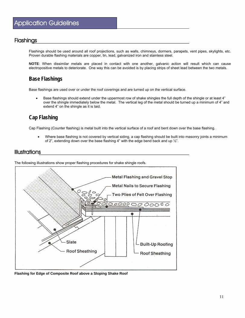
IIlllluussttrraattiioonnss The following illustrations show proper flashing procedures for shake shingle roofs.
Flashing for Edge of Composite Roof above a Sloping Shake Roof
Application Guidelines
12
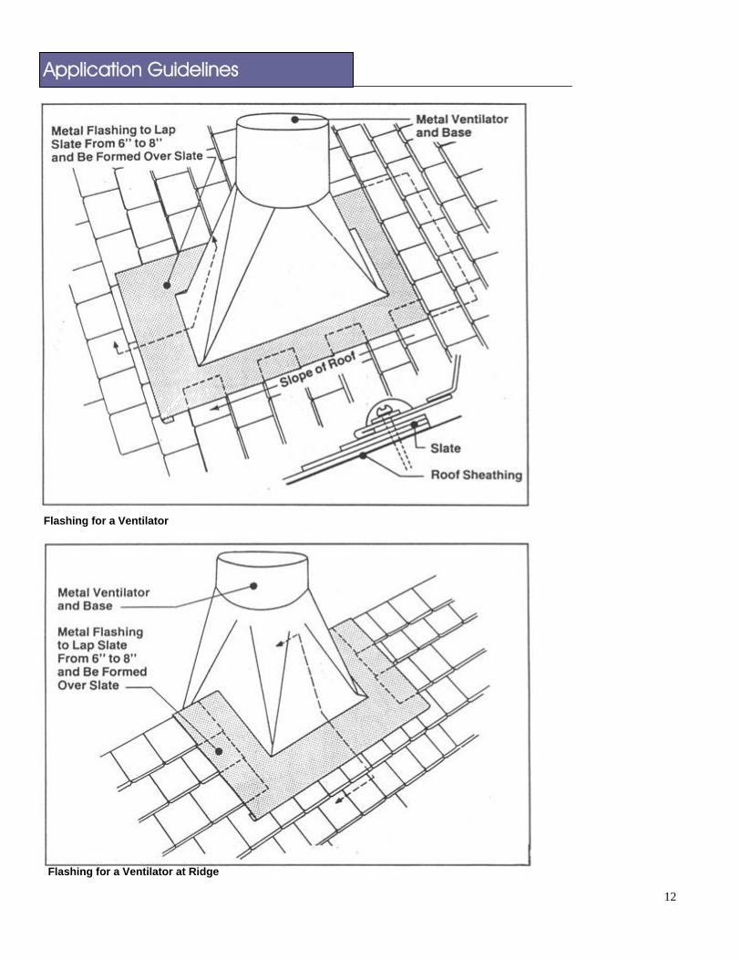
Flashing for a Ventilator
Flashing for a Ventilator at Ridge

Application Guidelines
13
Built-In Base Flashing for a Chimney
Flashing for a Chimney

Application Guidelines
14
Flashing for Chimney on Ridge
Built-In Base Flashing for a Dormer Window
Application Guidelines
15
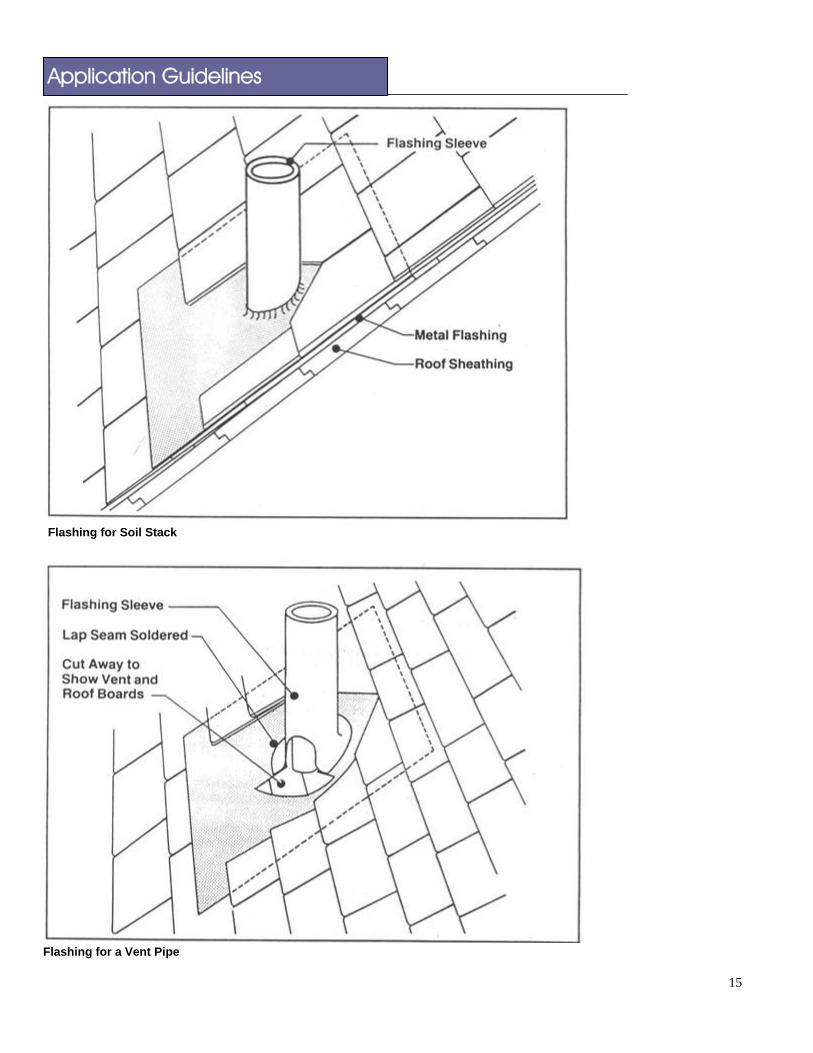
Flashing for Soil Stack
Flashing for a Vent Pipe

Application Guidelines
16
lashing for a Recessed Dormer WindowF

Application Guidelines
17
HHiipp && RRiiddggee DDeettaaiill
• Trim the hip shingles to fit as tight as possible. Install an 8" wide strip of 30 lb. felt minimum over the center of the hip.
• When pre-formed hip & ridge shingles are used, place nails at nail locator marks. Fasten hip shingles with 2 nails each on each side. Maintain a 3" head lap.