rp3410 rp3440 maint - iStorage Networks
120
hp 9000 rp3410 and rp3440 Maintenance Guide Regulatory Model Number: FCLSA-0201 Version 2.0 Manufacturing Part Number: rp3410_rp3440_maint June 2004 U.S.A. © Copyright 2004 Hewlett-Packard Development Company, L.P..
Transcript of rp3410 rp3440 maint - iStorage Networks

hp 9000 rp3410 and rp3440 Maintenance Guide
Regulatory Model Number: FCLSA-0201
Version 2.0
Manufacturing Part Number: rp3410_rp3440_maint
June 2004
U.S.A.
© Copyright 2004 Hewlett-Packard Development Company, L.P..

Legal NoticesCopyright Notices. ©Copyright 2004 Hewlett-Packard Development Company, L.P.
The information contained herein is subject to change without notice. The only warranties for HP products and services are set forth in the express warranty statements accompanying such products and services. Nothing herein should be construed as constituting an additional warranty. HP shall not be liable for technical or editorial errors or omissions contained herein.
Adobe and Acrobat are trademarks of Adobe Systems Incorporated. HP-UX Release 10.20 and later and HP-UX Release 11.00 and later (in both 32 and 64-bit configurations) on all HP 9000 computers are Open Group UNIX 95 branded products. Intel is a trademark or registered trademark of Intel Corporation or its subsidiaries in the United States and other countries. Linux is a registered trademark of Linus Torvalds. UNIX is a registered trademark of The Open Group. Windows is a registered trademark of Microsoft Corporation.
Printed in the U.S.A.
Reproduction, adaptation, or translation of this document without prior written permission is prohibited, except as allowed under the copyright laws.
Related Documents. The HP Server Documentation CD-ROM has been provided with your server. It contains a documentation set for the server, including localized versions of key documents. Included on the CD-ROM are the Site Preparation and Operations guides, which contain in-depth troubleshooting and repair information.
The CD will autorun when you insert it into a Windows® workstation, or, point your browser at the index.htm file located under the Start directory of the CD. All users, including UNIX®/Linux, can access a complete manual set by viewing the directory manuals. The manuals are in Adobe® Acrobat® Reader (pdf) format.
IMPORTANT The latest versions of these documents, and any updates to these documents, are posted under the appropriate server at http://docs.hp.com.
Where to Get Help. For online access to technical support information, self-solve tools, online assistance, community forums of IT experts, broad multivendor knowledge base, and monitoring and diagnostic tools, go to http://www.hp.com/support.
2

Contents
1. About This DocumentWhat’s in This Document . . . . . . . . . . . . . . . . . . . . . . . . . . . . . . . . . . . . . . . . . . . . . . . . . . . . . . . . . . . . . . 9
Typographical Conventions . . . . . . . . . . . . . . . . . . . . . . . . . . . . . . . . . . . . . . . . . . . . . . . . . . . . . . . . . . . 9Related Documents . . . . . . . . . . . . . . . . . . . . . . . . . . . . . . . . . . . . . . . . . . . . . . . . . . . . . . . . . . . . . . . . . . 10
2. TroubleshootingTroubleshooting Methodology . . . . . . . . . . . . . . . . . . . . . . . . . . . . . . . . . . . . . . . . . . . . . . . . . . . . . . . . . . 11Using the Front Panel Power Button . . . . . . . . . . . . . . . . . . . . . . . . . . . . . . . . . . . . . . . . . . . . . . . . . . . . 12Operating System Will Boot . . . . . . . . . . . . . . . . . . . . . . . . . . . . . . . . . . . . . . . . . . . . . . . . . . . . . . . . . . . 13
Support Tools Manager . . . . . . . . . . . . . . . . . . . . . . . . . . . . . . . . . . . . . . . . . . . . . . . . . . . . . . . . . . . . . 13Event Monitoring Service. . . . . . . . . . . . . . . . . . . . . . . . . . . . . . . . . . . . . . . . . . . . . . . . . . . . . . . . . . . . 13Management Processor. . . . . . . . . . . . . . . . . . . . . . . . . . . . . . . . . . . . . . . . . . . . . . . . . . . . . . . . . . . . . . 14
Operating System Will Not Boot. . . . . . . . . . . . . . . . . . . . . . . . . . . . . . . . . . . . . . . . . . . . . . . . . . . . . . . . 17Offline Diagnostic Environment (ODE). . . . . . . . . . . . . . . . . . . . . . . . . . . . . . . . . . . . . . . . . . . . . . . . . 17Disk and I/O Path Logging . . . . . . . . . . . . . . . . . . . . . . . . . . . . . . . . . . . . . . . . . . . . . . . . . . . . . . . . . . . 18
Identifying and Diagnosing Hardware Problems. . . . . . . . . . . . . . . . . . . . . . . . . . . . . . . . . . . . . . . . . . . 19Troubleshooting Using LEDs . . . . . . . . . . . . . . . . . . . . . . . . . . . . . . . . . . . . . . . . . . . . . . . . . . . . . . . . . 19
LAN LEDs . . . . . . . . . . . . . . . . . . . . . . . . . . . . . . . . . . . . . . . . . . . . . . . . . . . . . . . . . . . . . . . . . . . . . . . . . 27System Board Diagnostic LEDs . . . . . . . . . . . . . . . . . . . . . . . . . . . . . . . . . . . . . . . . . . . . . . . . . . . . . . . . 28Cleaning Procedures . . . . . . . . . . . . . . . . . . . . . . . . . . . . . . . . . . . . . . . . . . . . . . . . . . . . . . . . . . . . . . . . . 30
3. Removing and Replacing ComponentsSafety Information . . . . . . . . . . . . . . . . . . . . . . . . . . . . . . . . . . . . . . . . . . . . . . . . . . . . . . . . . . . . . . . . . . . 31Service Tools Required. . . . . . . . . . . . . . . . . . . . . . . . . . . . . . . . . . . . . . . . . . . . . . . . . . . . . . . . . . . . . . . . 31Location of Internal Components and Connectors . . . . . . . . . . . . . . . . . . . . . . . . . . . . . . . . . . . . . . . . . . 32Removing and Replacing System Covers and Bezels. . . . . . . . . . . . . . . . . . . . . . . . . . . . . . . . . . . . . . . . 34
Tower Configuration . . . . . . . . . . . . . . . . . . . . . . . . . . . . . . . . . . . . . . . . . . . . . . . . . . . . . . . . . . . . . . . . 34Rack-Mount System . . . . . . . . . . . . . . . . . . . . . . . . . . . . . . . . . . . . . . . . . . . . . . . . . . . . . . . . . . . . . . . . 39
Removing and Replacing Hot-swap and Hot-plug Devices . . . . . . . . . . . . . . . . . . . . . . . . . . . . . . . . . . . 45Removing and Replacing System Fans . . . . . . . . . . . . . . . . . . . . . . . . . . . . . . . . . . . . . . . . . . . . . . . . . 45Removing and Replacing the Power Supply . . . . . . . . . . . . . . . . . . . . . . . . . . . . . . . . . . . . . . . . . . . . . 47Removing and Replacing an Internal Hard Disk Drive . . . . . . . . . . . . . . . . . . . . . . . . . . . . . . . . . . . . 49
Removing and Replacing Internal Components. . . . . . . . . . . . . . . . . . . . . . . . . . . . . . . . . . . . . . . . . . . . 55Removing and Replacing Airflow Guides . . . . . . . . . . . . . . . . . . . . . . . . . . . . . . . . . . . . . . . . . . . . . . . 55Removing and Replacing System Memory . . . . . . . . . . . . . . . . . . . . . . . . . . . . . . . . . . . . . . . . . . . . . . 59Removing and Replacing a Processor Module. . . . . . . . . . . . . . . . . . . . . . . . . . . . . . . . . . . . . . . . . . . . 62Removing and Replacing the System Battery. . . . . . . . . . . . . . . . . . . . . . . . . . . . . . . . . . . . . . . . . . . . 76Removing and Replacing PCI and Graphics Cards . . . . . . . . . . . . . . . . . . . . . . . . . . . . . . . . . . . . . . . 77Removing and Replacing PCI Cards . . . . . . . . . . . . . . . . . . . . . . . . . . . . . . . . . . . . . . . . . . . . . . . . . . . 79Removing and Replacing the PCI Backplane . . . . . . . . . . . . . . . . . . . . . . . . . . . . . . . . . . . . . . . . . . . . 81Removing and Replacing a Removable Media Drive . . . . . . . . . . . . . . . . . . . . . . . . . . . . . . . . . . . . . . 82Removing and Replacing the Management Processor Card. . . . . . . . . . . . . . . . . . . . . . . . . . . . . . . . . 84Removing and Replacing the Management Processor Card Battery . . . . . . . . . . . . . . . . . . . . . . . . . . 86Removing and Replacing the LED Status Panel. . . . . . . . . . . . . . . . . . . . . . . . . . . . . . . . . . . . . . . . . . 88Removing and Replacing the System Board . . . . . . . . . . . . . . . . . . . . . . . . . . . . . . . . . . . . . . . . . . . . . 89Removing and Replacing the Power Supply Interface Module . . . . . . . . . . . . . . . . . . . . . . . . . . . . . . 96
3

Contents
Removing and Replacing the Hard Disk Drive (SCSI) Backplane. . . . . . . . . . . . . . . . . . . . . . . . . . . . 99
A. Parts InformationField Replaceable Parts (FRU) List . . . . . . . . . . . . . . . . . . . . . . . . . . . . . . . . . . . . . . . . . . . . . . . . . . . . 105
B. System InformationFeatures Summary. . . . . . . . . . . . . . . . . . . . . . . . . . . . . . . . . . . . . . . . . . . . . . . . . . . . . . . . . . . . . . . . . . 111
Processor . . . . . . . . . . . . . . . . . . . . . . . . . . . . . . . . . . . . . . . . . . . . . . . . . . . . . . . . . . . . . . . . . . . . . . . . 111Memory . . . . . . . . . . . . . . . . . . . . . . . . . . . . . . . . . . . . . . . . . . . . . . . . . . . . . . . . . . . . . . . . . . . . . . . . . 111PCI Riser . . . . . . . . . . . . . . . . . . . . . . . . . . . . . . . . . . . . . . . . . . . . . . . . . . . . . . . . . . . . . . . . . . . . . . . . 111Internal Core I/O. . . . . . . . . . . . . . . . . . . . . . . . . . . . . . . . . . . . . . . . . . . . . . . . . . . . . . . . . . . . . . . . . . 111External Core I/O . . . . . . . . . . . . . . . . . . . . . . . . . . . . . . . . . . . . . . . . . . . . . . . . . . . . . . . . . . . . . . . . . 112Power Supply Unit . . . . . . . . . . . . . . . . . . . . . . . . . . . . . . . . . . . . . . . . . . . . . . . . . . . . . . . . . . . . . . . . 112Motherboard Manageability. . . . . . . . . . . . . . . . . . . . . . . . . . . . . . . . . . . . . . . . . . . . . . . . . . . . . . . . . 112Enhanced Server Manageability Using Management Processor . . . . . . . . . . . . . . . . . . . . . . . . . . . . 112Hard Disk Drives . . . . . . . . . . . . . . . . . . . . . . . . . . . . . . . . . . . . . . . . . . . . . . . . . . . . . . . . . . . . . . . . . 112
System Board . . . . . . . . . . . . . . . . . . . . . . . . . . . . . . . . . . . . . . . . . . . . . . . . . . . . . . . . . . . . . . . . . . . . . . 113System Board Components . . . . . . . . . . . . . . . . . . . . . . . . . . . . . . . . . . . . . . . . . . . . . . . . . . . . . . . . . 113PA RISC Processor . . . . . . . . . . . . . . . . . . . . . . . . . . . . . . . . . . . . . . . . . . . . . . . . . . . . . . . . . . . . . . . . 114Processor Bus . . . . . . . . . . . . . . . . . . . . . . . . . . . . . . . . . . . . . . . . . . . . . . . . . . . . . . . . . . . . . . . . . . . . 114ZX1 I/O and Memory Controller . . . . . . . . . . . . . . . . . . . . . . . . . . . . . . . . . . . . . . . . . . . . . . . . . . . . . 114Memory . . . . . . . . . . . . . . . . . . . . . . . . . . . . . . . . . . . . . . . . . . . . . . . . . . . . . . . . . . . . . . . . . . . . . . . . . 114I/O Bus Interface. . . . . . . . . . . . . . . . . . . . . . . . . . . . . . . . . . . . . . . . . . . . . . . . . . . . . . . . . . . . . . . . . . 116Processor Dependent Hardware (PDH) Controller . . . . . . . . . . . . . . . . . . . . . . . . . . . . . . . . . . . . . . . 117Field Programmable Gate Array (FGPA) . . . . . . . . . . . . . . . . . . . . . . . . . . . . . . . . . . . . . . . . . . . . . . 117Baseboard Management Controller (BMC) . . . . . . . . . . . . . . . . . . . . . . . . . . . . . . . . . . . . . . . . . . . . . 117SCSI Controller. . . . . . . . . . . . . . . . . . . . . . . . . . . . . . . . . . . . . . . . . . . . . . . . . . . . . . . . . . . . . . . . . . . 118IDE Interface . . . . . . . . . . . . . . . . . . . . . . . . . . . . . . . . . . . . . . . . . . . . . . . . . . . . . . . . . . . . . . . . . . . . 1181GB System LAN . . . . . . . . . . . . . . . . . . . . . . . . . . . . . . . . . . . . . . . . . . . . . . . . . . . . . . . . . . . . . . . . . 118USB Connectors . . . . . . . . . . . . . . . . . . . . . . . . . . . . . . . . . . . . . . . . . . . . . . . . . . . . . . . . . . . . . . . . . . 118
Index . . . . . . . . . . . . . . . . . . . . . . . . . . . . . . . . . . . . . . . . . . . . . . . . . . . . . . . . . . . . . . . . . . . . . . 119
4

Figures
Figure 2-1. Control Panel LEDs . . . . . . . . . . . . . . . . . . . . . . . . . . . . . . . . . . . . . . . . . . . . . . . . . . . . . 19Figure 2-2. Location of the STBY, F/W and BMC LEDs . . . . . . . . . . . . . . . . . . . . . . . . . . . . . . . . . . 28Figure 3-1. Internal Physical Layout . . . . . . . . . . . . . . . . . . . . . . . . . . . . . . . . . . . . . . . . . . . . . . . . . 32Figure 3-2. System Board Connectors and Slots . . . . . . . . . . . . . . . . . . . . . . . . . . . . . . . . . . . . . . . . 33Figure 3-3. Removing the Plastic Cover . . . . . . . . . . . . . . . . . . . . . . . . . . . . . . . . . . . . . . . . . . . . . . . 35Figure 3-4. Removing the Metal Cover . . . . . . . . . . . . . . . . . . . . . . . . . . . . . . . . . . . . . . . . . . . . . . . . 35Figure 3-5. Metal Cover Alignment Mark . . . . . . . . . . . . . . . . . . . . . . . . . . . . . . . . . . . . . . . . . . . . . 36Figure 3-6. Replacing the Metal Cover . . . . . . . . . . . . . . . . . . . . . . . . . . . . . . . . . . . . . . . . . . . . . . . . 37Figure 3-7. Replacing the Plastic Cover . . . . . . . . . . . . . . . . . . . . . . . . . . . . . . . . . . . . . . . . . . . . . . . 37Figure 3-8. Front Bezel . . . . . . . . . . . . . . . . . . . . . . . . . . . . . . . . . . . . . . . . . . . . . . . . . . . . . . . . . . . . 38Figure 3-9. Aligning the Tower Front Bezel . . . . . . . . . . . . . . . . . . . . . . . . . . . . . . . . . . . . . . . . . . . . 39Figure 3-10. Release the Rack Latches . . . . . . . . . . . . . . . . . . . . . . . . . . . . . . . . . . . . . . . . . . . . . . . . 40Figure 3-11. Removing and Replacing the Metal Cover . . . . . . . . . . . . . . . . . . . . . . . . . . . . . . . . . . 41Figure 3-12. Aligning the Metal Cover . . . . . . . . . . . . . . . . . . . . . . . . . . . . . . . . . . . . . . . . . . . . . . . . 42Figure 3-13. Closing the Metal Cover . . . . . . . . . . . . . . . . . . . . . . . . . . . . . . . . . . . . . . . . . . . . . . . . . 42Figure 3-14. Front Bezel Retaining Clip . . . . . . . . . . . . . . . . . . . . . . . . . . . . . . . . . . . . . . . . . . . . . . . 43Figure 3-15. Replacing the Front Bezel . . . . . . . . . . . . . . . . . . . . . . . . . . . . . . . . . . . . . . . . . . . . . . . 44Figure 3-16. Fan 1A or Fan 1B Removal. . . . . . . . . . . . . . . . . . . . . . . . . . . . . . . . . . . . . . . . . . . . . . . 46Figure 3-17. Fan 2 Removal. . . . . . . . . . . . . . . . . . . . . . . . . . . . . . . . . . . . . . . . . . . . . . . . . . . . . . . . . 46Figure 3-18. Fan 3 Removal. . . . . . . . . . . . . . . . . . . . . . . . . . . . . . . . . . . . . . . . . . . . . . . . . . . . . . . . . 47Figure 3-19. Releasing the Power Supply Retaining Clip . . . . . . . . . . . . . . . . . . . . . . . . . . . . . . . . . 48Figure 3-20. Removing the Power Supply. . . . . . . . . . . . . . . . . . . . . . . . . . . . . . . . . . . . . . . . . . . . . . 48Figure 3-21. Replacing the Power Supply. . . . . . . . . . . . . . . . . . . . . . . . . . . . . . . . . . . . . . . . . . . . . . 49Figure 3-22. Unlocking the Disk Drive . . . . . . . . . . . . . . . . . . . . . . . . . . . . . . . . . . . . . . . . . . . . . . . . 51Figure 3-23. Releasing the Disk Drive . . . . . . . . . . . . . . . . . . . . . . . . . . . . . . . . . . . . . . . . . . . . . . . . 51Figure 3-24. Removing the Disk Drive . . . . . . . . . . . . . . . . . . . . . . . . . . . . . . . . . . . . . . . . . . . . . . . . 52Figure 3-25. Removing Disk Drive Slot Filler . . . . . . . . . . . . . . . . . . . . . . . . . . . . . . . . . . . . . . . . . . 53Figure 3-26. Hard Disk Drive Installation . . . . . . . . . . . . . . . . . . . . . . . . . . . . . . . . . . . . . . . . . . . . . 53Figure 3-27. Airflow Guides Locations . . . . . . . . . . . . . . . . . . . . . . . . . . . . . . . . . . . . . . . . . . . . . . . . 56Figure 3-28. Removing the Memory Airflow Guide . . . . . . . . . . . . . . . . . . . . . . . . . . . . . . . . . . . . . . 56Figure 3-29. Removing the Processor Airflow Guide . . . . . . . . . . . . . . . . . . . . . . . . . . . . . . . . . . . . . 57Figure 3-30. Open the Release Clip. . . . . . . . . . . . . . . . . . . . . . . . . . . . . . . . . . . . . . . . . . . . . . . . . . . 58Figure 3-31. Remove the Front Airflow Guide . . . . . . . . . . . . . . . . . . . . . . . . . . . . . . . . . . . . . . . . . . 58Figure 3-32. DIMM Slot Identification . . . . . . . . . . . . . . . . . . . . . . . . . . . . . . . . . . . . . . . . . . . . . . . . 60Figure 3-33. Inserting DIMM into Slot . . . . . . . . . . . . . . . . . . . . . . . . . . . . . . . . . . . . . . . . . . . . . . . . 62Figure 3-34. Disconnect Power Pod Cable . . . . . . . . . . . . . . . . . . . . . . . . . . . . . . . . . . . . . . . . . . . . . 63Figure 3-35. Remove Power Pod Mounting Screws . . . . . . . . . . . . . . . . . . . . . . . . . . . . . . . . . . . . . . 64Figure 3-36. Disconnect Power Pod from Processor Module . . . . . . . . . . . . . . . . . . . . . . . . . . . . . . . 64Figure 3-37. Remove Power Pod . . . . . . . . . . . . . . . . . . . . . . . . . . . . . . . . . . . . . . . . . . . . . . . . . . . . . 65Figure 3-38. Disconnect the Turbo Fan Cable . . . . . . . . . . . . . . . . . . . . . . . . . . . . . . . . . . . . . . . . . . 66Figure 3-39. Release Heatsink Captive Screws . . . . . . . . . . . . . . . . . . . . . . . . . . . . . . . . . . . . . . . . . 66Figure 3-40. Slide Sequencing Retainer Plate . . . . . . . . . . . . . . . . . . . . . . . . . . . . . . . . . . . . . . . . . . 67Figure 3-41. Unlock Processor Module Locking Mechanism . . . . . . . . . . . . . . . . . . . . . . . . . . . . . . . 68
5

Figures
Figure 3-42. Remove Processor Module . . . . . . . . . . . . . . . . . . . . . . . . . . . . . . . . . . . . . . . . . . . . . . . 69Figure 3-43. Processor Module Removal/Replacement . . . . . . . . . . . . . . . . . . . . . . . . . . . . . . . . . . . 70Figure 3-44. Unlocking the Processor Module Locking Mechanism . . . . . . . . . . . . . . . . . . . . . . . . . 71Figure 3-45. Aligning the Processor Module. . . . . . . . . . . . . . . . . . . . . . . . . . . . . . . . . . . . . . . . . . . . 71Figure 3-46. Locking the Processor Module in Place . . . . . . . . . . . . . . . . . . . . . . . . . . . . . . . . . . . . . 72Figure 3-47. Slide the Sequencing Retainer Plate . . . . . . . . . . . . . . . . . . . . . . . . . . . . . . . . . . . . . . . 72Figure 3-48. Secure the Captive Screws . . . . . . . . . . . . . . . . . . . . . . . . . . . . . . . . . . . . . . . . . . . . . . . 73Figure 3-49. Aligning the Processor Module Power Pod . . . . . . . . . . . . . . . . . . . . . . . . . . . . . . . . . . 73Figure 3-50. Install the Processor Module Power Pod Mounting Screws . . . . . . . . . . . . . . . . . . . . . 74Figure 3-51. Connecting the Power Pod Cable . . . . . . . . . . . . . . . . . . . . . . . . . . . . . . . . . . . . . . . . . . 74Figure 3-52. Removing the System Battery . . . . . . . . . . . . . . . . . . . . . . . . . . . . . . . . . . . . . . . . . . . . 76Figure 3-53. Removing the PCI Cage . . . . . . . . . . . . . . . . . . . . . . . . . . . . . . . . . . . . . . . . . . . . . . . . . 78Figure 3-54. Removing the PCI Cage Cover . . . . . . . . . . . . . . . . . . . . . . . . . . . . . . . . . . . . . . . . . . . . 78Figure 3-55. Installing a PCI Slot Cover. . . . . . . . . . . . . . . . . . . . . . . . . . . . . . . . . . . . . . . . . . . . . . . 80Figure 3-56. Installing a PCI Card . . . . . . . . . . . . . . . . . . . . . . . . . . . . . . . . . . . . . . . . . . . . . . . . . . . 80Figure 3-57. Removing the PCI Backplane. . . . . . . . . . . . . . . . . . . . . . . . . . . . . . . . . . . . . . . . . . . . . 81Figure 3-58. Replacing the PCI Backplane. . . . . . . . . . . . . . . . . . . . . . . . . . . . . . . . . . . . . . . . . . . . . 82Figure 3-59. Removable Media Drive Removal/Replacement . . . . . . . . . . . . . . . . . . . . . . . . . . . . . . 83Figure 3-60. Removing the Management Processor. . . . . . . . . . . . . . . . . . . . . . . . . . . . . . . . . . . . . . 85Figure 3-61. Replace the Management Processor Blank . . . . . . . . . . . . . . . . . . . . . . . . . . . . . . . . . . 85Figure 3-62. Removing the Management Processor Battery . . . . . . . . . . . . . . . . . . . . . . . . . . . . . . . 87Figure 3-63. Removing the LED Status Panel . . . . . . . . . . . . . . . . . . . . . . . . . . . . . . . . . . . . . . . . . . 88Figure 3-64. Remove System Board Mounting Screws . . . . . . . . . . . . . . . . . . . . . . . . . . . . . . . . . . . 90Figure 3-65. Remove the System Board Mounting Screw . . . . . . . . . . . . . . . . . . . . . . . . . . . . . . . . . 91Figure 3-66. Remove the System Board . . . . . . . . . . . . . . . . . . . . . . . . . . . . . . . . . . . . . . . . . . . . . . . 91Figure 3-67. Slide System Board into Chassis . . . . . . . . . . . . . . . . . . . . . . . . . . . . . . . . . . . . . . . . . . 92Figure 3-68. Align the System Board PCI Connector . . . . . . . . . . . . . . . . . . . . . . . . . . . . . . . . . . . . 93Figure 3-69. Slide System Board in Chassis. . . . . . . . . . . . . . . . . . . . . . . . . . . . . . . . . . . . . . . . . . . . 94Figure 3-70. Install the Rear Panel Mounting Screws. . . . . . . . . . . . . . . . . . . . . . . . . . . . . . . . . . . . 95Figure 3-71. Reinstall the Power Connectors . . . . . . . . . . . . . . . . . . . . . . . . . . . . . . . . . . . . . . . . . . . 95Figure 3-72. Power Cables and Holding Clips . . . . . . . . . . . . . . . . . . . . . . . . . . . . . . . . . . . . . . . . . . 97Figure 3-73. Remove the Mounting Screw . . . . . . . . . . . . . . . . . . . . . . . . . . . . . . . . . . . . . . . . . . . . . 97Figure 3-74. Remove the PSI Interface Module . . . . . . . . . . . . . . . . . . . . . . . . . . . . . . . . . . . . . . . . . 98Figure 3-75. Replacing the Power Supply Interface Module . . . . . . . . . . . . . . . . . . . . . . . . . . . . . . . 98Figure 3-76. Securing the Power Supply Interface Module and Cables . . . . . . . . . . . . . . . . . . . . . . 99Figure 3-77. Open the Fan Power Bridge . . . . . . . . . . . . . . . . . . . . . . . . . . . . . . . . . . . . . . . . . . . . . 100Figure 3-78. Disconnect SCSI Cables . . . . . . . . . . . . . . . . . . . . . . . . . . . . . . . . . . . . . . . . . . . . . . . . 101Figure 3-79. Remove Mounting Screws. . . . . . . . . . . . . . . . . . . . . . . . . . . . . . . . . . . . . . . . . . . . . . . 101Figure 3-80. Remove the SCSI Backplane . . . . . . . . . . . . . . . . . . . . . . . . . . . . . . . . . . . . . . . . . . . . 102Figure 3-81. Remove the SCSI Backplane from Chassis . . . . . . . . . . . . . . . . . . . . . . . . . . . . . . . . . 102Figure A-1. Parts Identification. . . . . . . . . . . . . . . . . . . . . . . . . . . . . . . . . . . . . . . . . . . . . . . . . . . . . 105Figure A-2. Tower Parts . . . . . . . . . . . . . . . . . . . . . . . . . . . . . . . . . . . . . . . . . . . . . . . . . . . . . . . . . . . 106Figure B-1. System Block Diagram. . . . . . . . . . . . . . . . . . . . . . . . . . . . . . . . . . . . . . . . . . . . . . . . . . 113
6
Figures
Figure B-2. Memory Block Diagram . . . . . . . . . . . . . . . . . . . . . . . . . . . . . . . . . . . . . . . . . . . . . . . . . 115
7

Figures
8

1 About This Document
This document describes how to maintain your hp 9000 rp3410 or hp 9000 rp3440 Server, Regulatory Model Number: FCLSA-0201.
The document printing date and part number indicate the document’s current edition. The printing date will change when a new edition is printed. Minor changes may be made at reprint without changing the printing date. The document part number will change when extensive changes are made.
Document updates may be issued between editions to correct errors or document product changes. To ensure that you receive the updated or new editions, you should subscribe to the appropriate product support service. Contact your HP sales representative for details.
The latest version of this document can be found online at http://docs.hp.com.
NOTE Additional information about the hp 9000 rp3410 or rp3440 Server is provided in the associated User Guides. These guides are available on the HP Server Documentation CD-ROM and online at http://docs.hp.com.
What’s in This DocumentThe hp 9000 rp3410 and hp 9000 rp3440 Maintenance Guide contains these chapters:
• Chapter 2, “Troubleshooting.” Use this chapter to learn how to perform minimal troubleshooting of your system
• Chapter 3, “Removing and Replacing Components.” Use this chapter to learn how to remove and replace all Field Replaceable Units (FRUs) in your system
• Appendix A, “Parts Information.” Use this appendix to identify FRU part numbers
• Appendix B, “System Information.” Use this appendix to learn the basic system information of your HP Server
Typographical Conventions
This document uses the following conventions.
Title The title of a document or a CD.
KeyCap The name of a keyboard key. Note that Return and Enter both refer to the same key.
Emphasis Text that is emphasized.
Bold Text that is strongly emphasized, such as the summary text in bulleted paragraphs.
ComputerOut Text displayed by the computer.
UserInput Commands and other text that you type.
Command A command name or qualified command phrase.
Chapter 1 9
About This DocumentRelated Documents
Related DocumentsThe HP Server Documentation CD-ROM has been provided with your server. It contains a complete documentation set for the server, including localized versions of key documents. Included on the CD-ROM are the Site Preparation, Installation, and Operations guides, which contain in-depth installation and troubleshooting information.
The CD will autorun when you insert it into a Windows workstation, or, point your browser at the index.htm file located under the Start directory of the CD. All users, including UNIX/Linux, can access a complete manual set by viewing the directory manuals. The manuals are in Adobe Acrobat Reader (pdf) format.
IMPORTANT The latest versions of these documents, and any updates to these documents, are posted under the appropriate server at http://docs.hp.com.
Chapter 110

2 Troubleshooting
This chapter provides troubleshooting instructions for maintaining your hp 9000 rp3410 or hp 9000 rp3440 Server.
Troubleshooting Methodology
WARNING Before removing a cover, always disconnect the AC power cord and unplug telephone cables. Disconnect the AC power cord to avoid exposure to high energy levels that may cause burns when parts are short-circuited by metal objects such as tools or jewelry.
CAUTION Do not operate the HP Server for more than 5 minutes with any cover (including disk drives) removed. Damage to system components may result due to improper cooling airflow.
To troubleshoot your system you must be familiar with the HP-UX operating system and be able to start and stop testing processes. You should also be familiar with Support Tools Manager (STM), which runs in HP-UX, and the Offline Diagnostics Environment (ODE).
Online troubleshooting programs are available on your HP-UX operating system. Offline troubleshooting programs are available on the resource CD that is shipped with your HP Server. Descriptions and user information about offline troubleshooting tools are available at http://docs.hp.com. The offline tools are available for downloading at http://software.hp.com.
Chapter 2 11

TroubleshootingUsing the Front Panel Power Button
Using the Front Panel Power ButtonThe server power button on the front panel operates differently, depending on how long the button is held in and on what the system is doing when the button is pressed. You must be aware of its uses to properly troubleshoot the system. Power button functions are described in the following table.
Table 2-1 Power Button Functions
System State Switch Pressed Time Result
Power connected to power supplies—system power off
1 second or less
More than 1 second
System power on
No effect
System at ISL Less than 1 second
More than 1 second but less than 5 seconds
More than 5 seconds
No effect
Not used. This selection initiates E-buzzer functions that are not supported in the hp 9000 rp3410 and hp 9000 rp3440 servers
Hard shutdown
System at BCH Less than 1 second
More than 1 second but less than 5 seconds
More than 5 seconds
Hard shutdown
Not used. This selection initiates E-buzzer functions that are not supported in the hp 9000 rp3410 and hp 9000 rp3440 servers
Hard shutdown
Power on—OS shut down Less than 1 second
More than 1 second but less than 5 seconds
More than 5 seconds
No effect
Not used. This selection initiates E-buzzer functions that are not supported in the hp 9000 rp3410 and hp 9000 rp3440 servers
Hard shutdown
OS running Less than 1 second
More than 1 second but less than 5 seconds
More than 5 seconds
No effect
Not used. This selection initiates E-buzzer functions that are not supported in the hp 9000 rp3410 and hp 9000 rp3440 servers
Hard shutdown
Chapter 212

TroubleshootingOperating System Will Boot
Operating System Will BootIf your operating system is running and you are experiencing problems, use the following online tools to help solve your problem:
• Support Tools Manager (STM)
• Event Monitoring Service (EMS)
• Management Processor (MP)
Support Tools Manager
Support Tools Manager (STM) is available in three user interfaces:
• Graphical interface for X-based terminals (XSTM)
• Menu interface for ASCII terminals (MSTM)
• Command line interface for all ASCII terminals (CSTM)
You can use the graphical and menu interfaces intuitively and you can use the command line interface to drive STM using scripts.
You can use diagnostics to thoroughly test a device and isolate failures down to the suspected Field Replaceable Unit (FRU).
For complete documentation on how to access and use STM go to http://docs.hp.com. Under Topics menu go to Diagnostics and look for Support Tools Manager.
Event Monitoring Service
Event Monitoring Service (EMS) is the framework for monitoring hardware and reporting events. You can use EMS to eliminate most undetected hardware failures that cause data loss or interruptions of system operation. You can monitor a hardware device (such as a disk) for the occurrence of any unusual activity (called an event). When an event occurs, it is reported by a variety of notification methods such as e-mail. Event detections are handled automatically with minimal involvement on your part.
The following monitors are available:
• CMC monitor
• UPS monitor
• FC hub monitor
• FC switch monitor
• Peripheral status monitor
• Memory monitor
EMS comes with your HP-UX operating system. To bring up the event monitoring main menu, execute the following command at the shell prompt:
/etc/opt/resmon/lbin/monconfig
From the list of main menu selections, choose:
(E) Enable Monitoring
Chapter 2 13

TroubleshootingOperating System Will Boot
Management Processor
The Management Processor (MP) interface provides access to the baseboard management controller system information and provides some configuration capabilities. By viewing the system logs by way of the MP you can view information that can assist in solving problems affecting your server. To access your MP interface and system logs, perform the following steps:
NOTE The MP interface must be accessed from a terminal console that is attached to the MP via the MP LAN or MP remote serial connector. The MP is always available for troubleshooting, regardless of the state of your system, as long as there is AC power applied to your server.
NOTE At publication, the current version of the Management Processor Revision is E.02.25.
Check the HP website for the latest revision.
Step 1. If necessary, press CTRL+B to access the MP interface.
Step 2. Log in with proper user name and password.
Step 3. Enter cl to display the console logs. This log displays console history from oldest to newest.
Step 4. Enter sl to display the system logs. The system logs consist of:
• System event
• Forward progress
• Current boot
• Previous boot
• Live events
• Clear SEL/FPL logs
Step 5. For a complete explanation of the management processor and all commands refer to the Utilities chapter of the hp 9000 rp3410 and rp3440 Operations Guide.
System Event Logs (SEL)
Step 1. Access the management processor command prompt.
Step 2. Run the sl command. The Event Log Viewer menu will display:
SL
Event Log Viewer:
Log Name Entries % Full Latest Entry
-------------------------------------------------------------------
E - System Event 9 1 % 29 Oct 2002 19:15:05
F - Forward Progress 129 3 %
Chapter 214
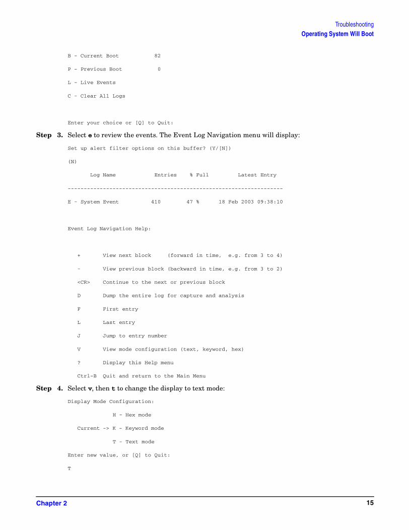
TroubleshootingOperating System Will Boot
B - Current Boot 82
P - Previous Boot 0
L - Live Events
C - Clear All Logs
Enter your choice or [Q] to Quit:
Step 3. Select e to review the events. The Event Log Navigation menu will display:
Set up alert filter options on this buffer? (Y/[N])
(N)
Log Name Entries % Full Latest Entry
-------------------------------------------------------------------
E - System Event 410 47 % 18 Feb 2003 09:38:10
Event Log Navigation Help:
+ View next block (forward in time, e.g. from 3 to 4)
- View previous block (backward in time, e.g. from 3 to 2)
<CR> Continue to the next or previous block
D Dump the entire log for capture and analysis
F First entry
L Last entry
J Jump to entry number
V View mode configuration (text, keyword, hex)
? Display this Help menu
Ctrl-B Quit and return to the Main Menu
Step 4. Select v, then t to change the display to text mode:
Display Mode Configuration:
H - Hex mode
Current -> K - Keyword mode
T - Text mode
Enter new value, or [Q] to Quit:
T
Chapter 2 15
TroubleshootingOperating System Will Boot
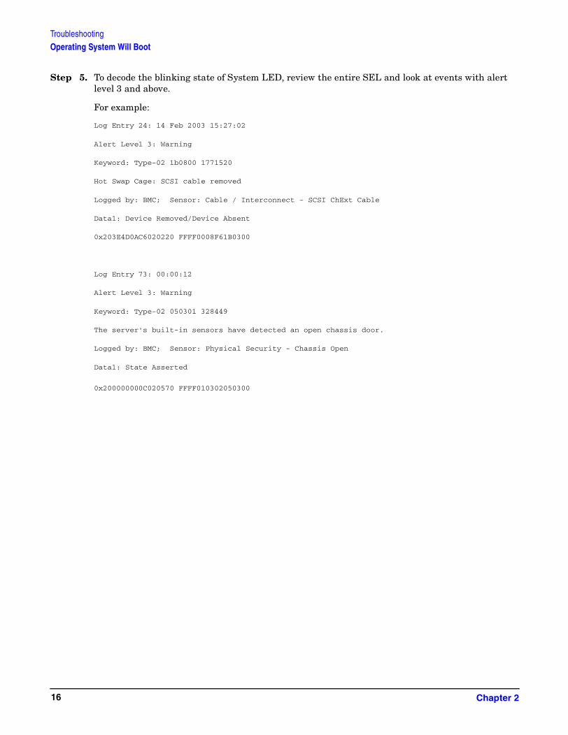
Step 5. To decode the blinking state of System LED, review the entire SEL and look at events with alert level 3 and above.
For example:
Log Entry 24: 14 Feb 2003 15:27:02
Alert Level 3: Warning
Keyword: Type-02 1b0800 1771520
Hot Swap Cage: SCSI cable removed
Logged by: BMC; Sensor: Cable / Interconnect - SCSI ChExt Cable
Data1: Device Removed/Device Absent
0x203E4D0AC6020220 FFFF0008F61B0300
Log Entry 73: 00:00:12
Alert Level 3: Warning
Keyword: Type-02 050301 328449
The server's built-in sensors have detected an open chassis door.
Logged by: BMC; Sensor: Physical Security - Chassis Open
Data1: State Asserted
0x200000000C020570 FFFF010302050300
Chapter 216
TroubleshootingOperating System Will Not Boot
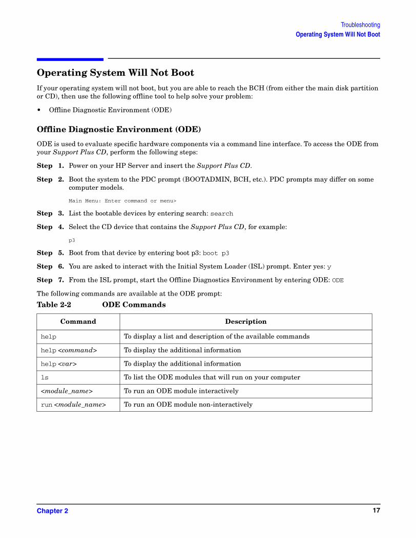
Operating System Will Not BootIf your operating system will not boot, but you are able to reach the BCH (from either the main disk partition or CD), then use the following offline tool to help solve your problem:
• Offline Diagnostic Environment (ODE)
Offline Diagnostic Environment (ODE)
ODE is used to evaluate specific hardware components via a command line interface. To access the ODE from your Support Plus CD, perform the following steps:
Step 1. Power on your HP Server and insert the Support Plus CD.
Step 2. Boot the system to the PDC prompt (BOOTADMIN, BCH, etc.). PDC prompts may differ on some computer models.
Main Menu: Enter command or menu>
Step 3. List the bootable devices by entering search: search
Step 4. Select the CD device that contains the Support Plus CD, for example:
p3
Step 5. Boot from that device by entering boot p3: boot p3
Step 6. You are asked to interact with the Initial System Loader (ISL) prompt. Enter yes: y
Step 7. From the ISL prompt, start the Offline Diagnostics Environment by entering ODE: ODE
The following commands are available at the ODE prompt:
Table 2-2 ODE Commands
Command Description
help To display a list and description of the available commands
help <command> To display the additional information
help <var> To display the additional information
ls To list the ODE modules that will run on your computer
<module_name> To run an ODE module interactively
run <module_name> To run an ODE module non-interactively
Chapter 2 17

TroubleshootingOperating System Will Not Boot
Disk and I/O Path Logging
Some failures result in I/O path logging. These paths help to indicate the source of the error and may be included in the error message or logged into console or event logs. The following table describes the disk drive and PCI slot paths for your HP Server.
Table 2-3 Internal Disk and DVD Paths
Slot Path
Slot 2 (top) 0/1/1/1.2
Slot 1 (middle) 0/1/1/0.1
Slot 0 (bottom) 0/1/1/0.0
DVD 0/0/2/0.0
Table 2-4 Extended Core I/O Paths
Function Path
Console Port 0/7/1/1.0
Remote Port 0/7/1/1.2
UPS Port 0/7/1/0.0
VGA Port 0/7/2/0 (disabled)
Table 2-5 PCI I/O Paths
I/O Slot Path
Slot 1 0/4
Slot 2 0/3
Slot 3 0/2 (Active for rp3440 only)
Slot 4 0/6 (Active for rp3440 only)
Chapter 218

TroubleshootingIdentifying and Diagnosing Hardware Problems
Identifying and Diagnosing Hardware ProblemsShould a hardware failure occur, the system LED, diagnostic LEDs and the System Event Log (SEL) will help you identify the problem:
• LEDs. The lights on the front bezel of the server change color and blink in different patterns to help identify specific hardware problems. LEDs on the rear panel of the server display LAN status
• The System Event Log (SEL) provides detailed information about the errors identified by the LEDs
Troubleshooting Using LEDs
Four diagnostic LEDs, one power LED, and one system LED are located on the control panel of the system. The following sections describe their functions. Additional diagnostic LEDs are provided on the system board (See “System Board Diagnostic LEDs” on page 28).
If the system has no Management Processor (MP) card installed, the four diagnostic LEDs on the front panel warn of impending failures and allow you to take preventive action. For example, you may want to back up your data or replace a component before it fails.
• If no management processor card is installed, the boot progress is monitored by diagnostic LEDs 1 through 4. During the boot-up the LEDs will turn on in sequence until the BCH prompt is reached
• If a management processor card is installed, the boot process will be monitored by the management processor card. The LEDs will be off
Figure 2-1 Control Panel LEDs
Power and System LEDs
The Power and System LEDs indicate the state of the system. When the system LED is blinking yellow or red, a problem exists.
Table 2-6 System LED States
System LED State
Off AC power off if Power LED is off
Solid green Running OS
Blinking green Booting or running EFI
1 2 3 4 LAN System
System LED
Power On/Off LED
Power Button
Diagnostics LEDs
Locator Button and LEDLAN LED
Chapter 2 19

TroubleshootingIdentifying and Diagnosing Hardware Problems
For system alerts of levels 3-5, the attention condition on the LED can be cleared by accessing the logs using the sl command available in the management processor command mode.
The fault condition for system alerts of level 7 can only be cleared with the dc command unless hardware replacement is necessary. Refer to the SL error logs for additional error information.
NOTE Always check the management processor status logs in the case of a blinking yellow or red System LED before replacing any hardware.
Diagnostic LEDs The four diagnostic LEDs on the front bezel of the system are used for diagnosing the health of the system. Refer to the SEL and FPL logs for specific information about the warning or failure indicated by the diagnostics LEDs.
These LEDs warn of impending hardware failures and allow you to take preventive action, such as making a system backup or replacing a component before it fails. These diagnostic LEDs are labeled 1, 2, 3 and 4.
The location of red LEDs can be used to identify the category of the fault or warning. For example, if LED one is red, there is a problem with memory. However, if LEDs one and two are both red, there is a problem with the system processor.
If the diagnostic LEDs indicate an error, check the SEL for a more detailed explanations of the failure.
• The System LED indicates the severity of the error. Check this LED before proceeding to analyze the sequence of diagnostic LEDs:
• Blinking yellow indicates a WARNING
• Blinking red indicates a FAULT
• The Diagnostic LEDs provide details about the specific error:
• Solid red indicates the failing part or subsystem
• Off or solid green diagnostic LEDs provide additional details about the failure
Blinking yellow (1/sec.) Attention:
Alerts of levels 3-5 detected in the management processor logs
The LED will turn off once the event log has been read
Blinking red (2/sec.) Fault:
System Alert 7 detected, LED will blink until the problem is resolved and the system boots successfully or until it is manually turned off with the management processor dc command
Fatal hardware error detected by BMC, LED will blink until problem is corrected
Table 2-6 System LED States (Continued)
System LED State
Chapter 220

TroubleshootingIdentifying and Diagnosing Hardware Problems
The faults and warnings fall into several general categories.
Warnings
The following tables provide additional information about each specific warning associated with the various possible LED lighting sequences when the system LED is yellow.
Table 2-7 Diagnostic LEDs Fault and Warning Categories
LED 1 LED 2 LED 3 LED 4 Category
Red Anya
a. This LED can display any color other than red (for example, green or off).
Anya Anya Memory
Anya Red Anya Anya Firmware
Anya Anya Red Anya System board
Anya Anya Anya Red Fan
Red Red Anya Anya Processor
Red Anya Red Anya BMC
Red Anya Anya Red Temperature
Anya Red Anya Red Power supply
Red Red Red Red Unknown
Table 2-8 Unknown Warning
System LED LED 1 LED 2 LED 3 LED 4 Problem Solution
Flashing Yellow
Red Red Red Red Unknown warning
View the SEL for additional information
Table 2-9 Memory Warnings
System LED LED 1 LED 2 LED 3 LED 4 Problem Solution
Flashing Yellow
Red Green Off Off Mismatched memory pairs
Review the information on installing memory in the hp9000 rp3410 and rp3440 Installation Guide
Flashing Yellow
Red Off Green Green Memory thermal load order
Review the information on installing memory in the hp9000 rp3410 and rp3440 Installation Guide
Chapter 2 21

TroubleshootingIdentifying and Diagnosing Hardware Problems
Flashing Yellow
Red Green Green Green Bad SPD information (can't detect type)
View the SEL for additional information
Table 2-10 System Board Warnings
System LED LED 1 LED 2 LED 3 LED 4 Problem Solution
Flashing Yellow
Green Green Red Off Battery voltage low
Replace the system board battery
Table 2-11 Fan Warnings
System LED LED 1 LED 2 LED 3 LED 4 Problem Solution
Flashing Yellow
Green Off Off Red Fan 1A is not functioning properly
Replace the fan that is not functioning
Flashing Yellow
Off Green Off Red Fan 1B is not functioning properly
Replace the fan that is not functioning
Flashing Yellow
Off Off Green Red CPU fan 0 is not functioning properly
Replace the fan that is not functioning
Flashing Yellow
Green Green Off Red CPU fan 1 is not functioning properly
Replace the fan that is not functioning. If a processor fan has failed, you must replace the CPU
Flashing Yellow
Off Green Green Red Fan module 2 (memory) is not functioning properly
Replace the fan that is not functioning. If a processor fan has failed, you must replace the CPU
Flashing Yellow
Green Green Green Red Fan module 3 (memory) is not functioning properly
Replace the fan that is not functioning
Table 2-9 Memory Warnings (Continued)
System LED LED 1 LED 2 LED 3 LED 4 Problem Solution
Chapter 222

TroubleshootingIdentifying and Diagnosing Hardware Problems
Faults The following tables provide additional information about each specific fault associated with the various possible LED lighting sequences when the system LED is red.
Table 2-12 Processor Warnings
System LED LED 1 LED 2 LED 3 LED 4 Problem Solution
Flashing Yellow
Red Red Green Off Processor 0 temperature exceeds limit
View the SEL for additional information. Make sure nothing is blocking the processor’s airflow
Flashing Yellow
Red Red Off Green Processor 1 temperature exceeds limit
View the SEL for additional information. Make sure nothing is blocking the processor’s airflow
Table 2-13 Temperature Warnings
System LED LED 1 LED 2 LED 3 LED 4 Problem Solution
Flashing Yellow
Red Green Green Red External air temperature too high
Make sure nothing is blocking the system’s airflow and place your system in an air-conditioned room
Table 2-14 Video Warnings
System LED LED 1 LED 2 LED 3 LED 4 Problem Solution
Flashing Yellow
Off Red Red Off No video adapter present
Install a video adapter. See the installation instructions shipped with the video adapter
Table 2-15 Power Supply Warnings
System LED LED 1 LED 2 LED 3 LED 4 Problem Solution
Flashing Yellow
Green Red Off Red Power supply 1 fault
Replace the power supply
Flashing Yellow
Off Red Green Red Power supply 2 fault
Replace the power supply
Table 2-16 Unknown Faults
System LED LED 1 LED 2 LED 3 LED 4 Problem Solution
Flashing Red
Red Red Red Red Unknown fault
View the SEL for additional information
Chapter 2 23

TroubleshootingIdentifying and Diagnosing Hardware Problems
Table 2-17 Memory Faults
System LED LED 1 LED 2 LED 3 LED 4 Problem Solution
Flashing Red
Red Green Off Off Mismatched memory pairs
Review the information on installing memory in the hp9000 rp3410 and rp3440 Installation Guide
Flashing Red
Red Off Off Green Uncorrectable memory error
Replace memory
Flashing Red
Red Green Green Off No memory installed
Install memory
Flashing Red
Red Green Green Green Bad Memory. One or more DIMMs are bad or not seated properly
Reseat the DIMMs. If the error persists, replace them
Table 2-18 Firmware Errors
System LED LED 1 LED 2 LED 3 LED 4 Problem Solution
Flashing Red
Off Red Off Off System firmware hang or system fault
View the SEL for additional information
Table 2-19 System Board Faults
System LED LED 1 LED 2 LED 3 LED 4 Problem Solution
Flashing Red
Off Green Red Off VRM overvoltage
View the SEL for additional information
Flashing Red
Green Off Red Off VRM undervoltage
View the SEL for additional information
Table 2-20 Fan Faults
System LED LED 1 LED 2 LED 3 LED 4 Problem Solution
Flashing Red
Green Off Off Red Cooling unit 1 fault (power)
Replace the fan that is not functioning
Chapter 224
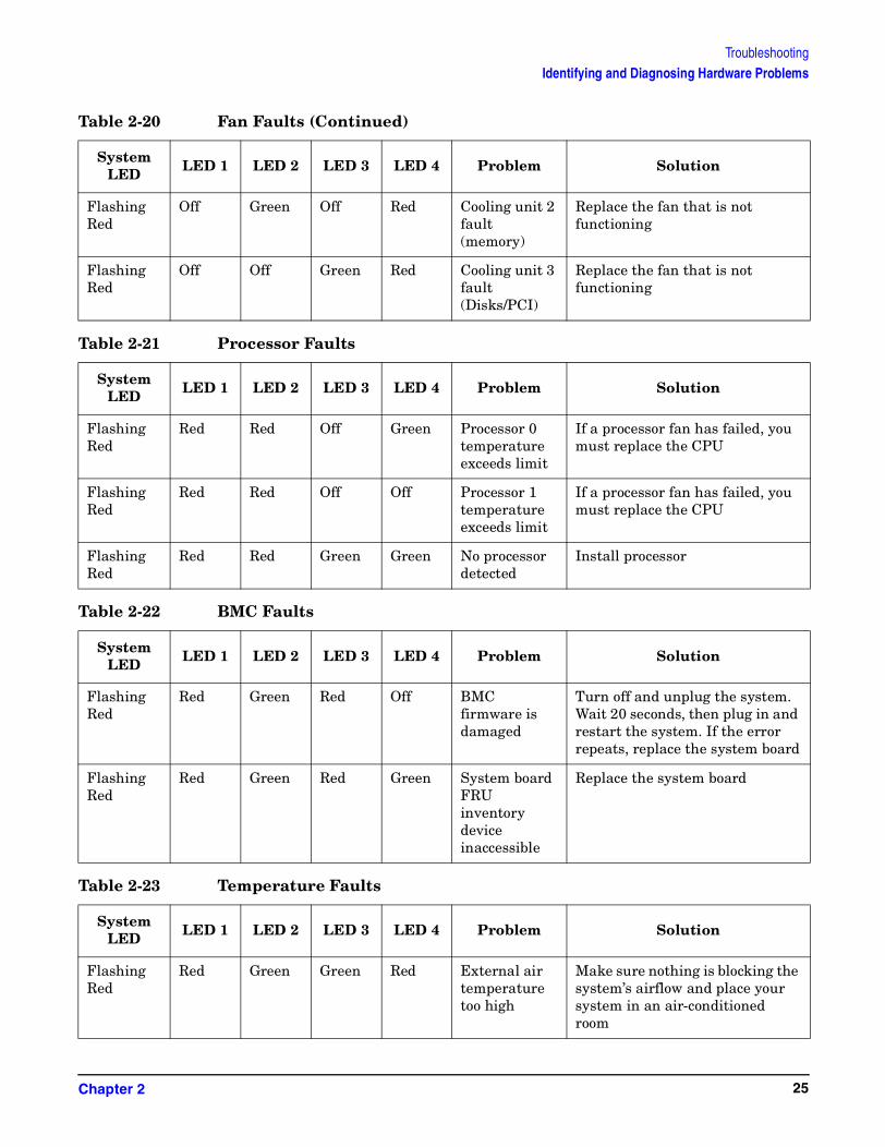
TroubleshootingIdentifying and Diagnosing Hardware Problems
Flashing Red
Off Green Off Red Cooling unit 2 fault (memory)
Replace the fan that is not functioning
Flashing Red
Off Off Green Red Cooling unit 3 fault (Disks/PCI)
Replace the fan that is not functioning
Table 2-21 Processor Faults
System LED LED 1 LED 2 LED 3 LED 4 Problem Solution
Flashing Red
Red Red Off Green Processor 0 temperature exceeds limit
If a processor fan has failed, you must replace the CPU
Flashing Red
Red Red Off Off Processor 1 temperature exceeds limit
If a processor fan has failed, you must replace the CPU
Flashing Red
Red Red Green Green No processor detected
Install processor
Table 2-22 BMC Faults
System LED LED 1 LED 2 LED 3 LED 4 Problem Solution
Flashing Red
Red Green Red Off BMC firmware is damaged
Turn off and unplug the system. Wait 20 seconds, then plug in and restart the system. If the error repeats, replace the system board
Flashing Red
Red Green Red Green System board FRU inventory device inaccessible
Replace the system board
Table 2-23 Temperature Faults
System LED LED 1 LED 2 LED 3 LED 4 Problem Solution
Flashing Red
Red Green Green Red External air temperature too high
Make sure nothing is blocking the system’s airflow and place your system in an air-conditioned room
Table 2-20 Fan Faults (Continued)
System LED LED 1 LED 2 LED 3 LED 4 Problem Solution
Chapter 2 25

TroubleshootingIdentifying and Diagnosing Hardware Problems
Table 2-24 Power Supply Errors
System LED LED 1 LED 2 LED 3 LED 4 Problem Solution
Flashing Red
Off Red Off Red VRM or power pod fault
View the SEL for additional information
Flashing Red
Green Red Off Red Power supply fault
View the SEL for additional information. Replace the power supply if necessary
Flashing Red
Green Red Green Red 12V out of range (power supply interface fault)
View the SEL for additional information. If the power supply interface has failed it is necessary to replace the base unit
Chapter 226

TroubleshootingLAN LEDs
LAN LEDsThe front panel LAN LED indicates the system is communicating over the Gigabit or system management LAN:
• Blinking green, the system is communicating over the LAN
• Solid green, LAN link is established, no current LAN activity
• Not green, no LAN cable attached, LAN network dead or the system is off
10/100/1000 LAN LEDs are on the rear panel:
Four management processor LAN LEDs are also on the rear panel if the system has a management processor card installed:
Table 2-25 10/100/1000 base-T Ethernet LAN Connector LEDs
LED Description
1000BT Blinking green—the 1000 MHz with ethernet protocol and twisted-pair wiring is enabled, off—no link
100BT Blinking green—the 100 MHz with ethernet protocol and twisted-pair wiring is enabled, off—no link
10BT Blinking green—the 10 MHz with ethernet protocol and twisted-pair wiring is enabled, off—no link
Activity Blinking green—LAN activity
Table 2-26 Management Processor Card LAN LEDs
LAN LED Location Color State
Self-test Top Yellow Management processor running selftest or error
Off Management processor has booted
10BT 2nd from top Green 10BT link established
Blinking green 10BT activity
Off No link or 100BT link
100BT 2nd from bottom Green 100BT link established
Blinking green 100BT activity
Off No link or 10BT link
Standby Power
Bottom Green Standby power on
Off Standby power off
Chapter 2 27

TroubleshootingSystem Board Diagnostic LEDs
System Board Diagnostic LEDsThere are three additional LEDs that can help when troubleshooting the system. These LEDs are located on the system board close to the back of the system and can be viewed through the small cooling holes in the system case.
Figure 2-2 Location of the STBY, F/W and BMC LEDs
The STBY LED may be viewed here
through the cooling vents
The BMC and F/W LEDs may be viewed here through the cooling vents.
BMC LED
STBY LEDF/W LED
Chapter 228
TroubleshootingSystem Board Diagnostic LEDs
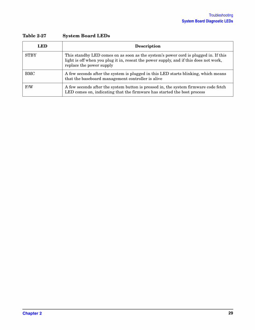
Table 2-27 System Board LEDs
LED Description
STBY This standby LED comes on as soon as the system’s power cord is plugged in. If this light is off when you plug it in, reseat the power supply, and if this does not work, replace the power supply
BMC A few seconds after the system is plugged in this LED starts blinking, which means that the baseboard management controller is alive
F/W A few seconds after the system button is pressed in, the system firmware code fetch LED comes on, indicating that the firmware has started the boot process
Chapter 2 29

TroubleshootingCleaning Procedures
Cleaning ProceduresThe following table identifies cleaning procedures for this hp 9000 rp3410 or hp 9000 rp3440 Server. Be sure to turn off power to the server when cleaning it.
CAUTION DO NOT use petroleum-based cleaners (such as lighter fluid) or cleaners containing benzene, trichlorethylene, ammonia, dilute ammonia, or acetone. These chemicals could damage all plastic and painted surfaces.
Table 2-28 Cleaning
Component Time Frame Cleaning Procedure
Keyboard Regularly Dust with damp, lint-free cloth
Monitor screen Regularly Use the HP Video Screen Cleaning Solution found in 92193M Master Clean Kit
Mouse Regularly Refer to the mouse's manual for mouse maintenance procedures
Cooling fans and grilles
6 Months Check functions of cooling fans and clean the intake openings on the chassis of dust, lint, and other obstructions to airflow
Chapter 230

3 Removing and Replacing Components
Safety InformationFollow the procedures listed below to ensure safe handling of components and to prevent harm to both you and the HP Server:
• Use an antistatic wrist strap and a grounding mat, such as those included in the Electrically Conductive Field Service Grounding Kit (HP 9300-1155)
• Handle accessory boards and components by the edges only. Do not touch any metal-edge connectors or any electrical components on accessory boards
• Do not wear clothing subject to static charge build-up, such as wool or synthetic materials
WARNING Hazardous voltages are present inside the HP Server. Always remove AC power from the server and associated assemblies while working inside the unit. Serious injury may result if this warning is not observed.
Service Tools RequiredService of this product may require one or more of the following tools:
• Electrically Conductive Field Service Kit (P/N 9300-1155)
• 1/4 inch flat blade screwdriver
• ACX-15 Torx® screwdriver
• Special processor tool kit, HP P/N 5069-5441
Chapter 3 31

Removing and Replacing ComponentsLocation of Internal Components and Connectors
Location of Internal Components and Connectors
Figure 3-1 Internal Physical Layout
Table 3-1 Component Locations
1 Power receptacles (PWR1 right, PWR2 left) 8 Hot-pluggable hard drives (up to 3)
2 HP ZX1 memory and I/O controller 9 Hard disk lock
3 Processor airflow guide 10 System fans (Fan 2 center, Fan 3 PCI cage)
4 System fans (Fan 1A right, Fan 1B left) 11 Intrusion switch
5 Slimline optical drive 12 Memory sockets
6 Power supplies (PSU1 center, PSU2 under optical drive)
13 PCI cage
7 Status panel board 14 Management controller card
1 23
4
5
7
89
10
14
13
12
11
6
Fan 1AFan 1B
PS 2
Drive 0 Drive 1
Drive 2
Pwr 2Pwr 1
PS 1Fan 3
Fan 2
Chapter 332

Removing and Replacing ComponentsLocation of Internal Components and Connectors
Figure 3-2 System Board Connectors and Slots
Table 3-2 Connector Locations
1 External SCSI connector 9 Memory and power supply fan connectors
17 PCI backplane connector
2 SCSI connectors A & B 10 Power module power connector 18 Optical drive connector
3 CPU power pods 11 HP ZX1 memory and I/O controller (under heatsink)
19 MP card connector
4 CPU 1 12 Memory sockets 20 HP ZX1 I/O adapter
5 CPU 0 13 Status panel connector 21 Serial ports (2)
6 Turbo fan power connectors 14 Power module auxiliary connector
22 USB connectors (4)
7 Five VRM cards 15 SCSI backplane power connector
23 LAN connector
8 Battery 16 PCI/memory fan cable connector
12
3
4
5
8910
16
14 13 12 11
6
15
17
18
19
20
21 22 23
7
SCSI CH A
SCSI CH B
Chapter 3 33
Removing and Replacing ComponentsRemoving and Replacing System Covers and Bezels
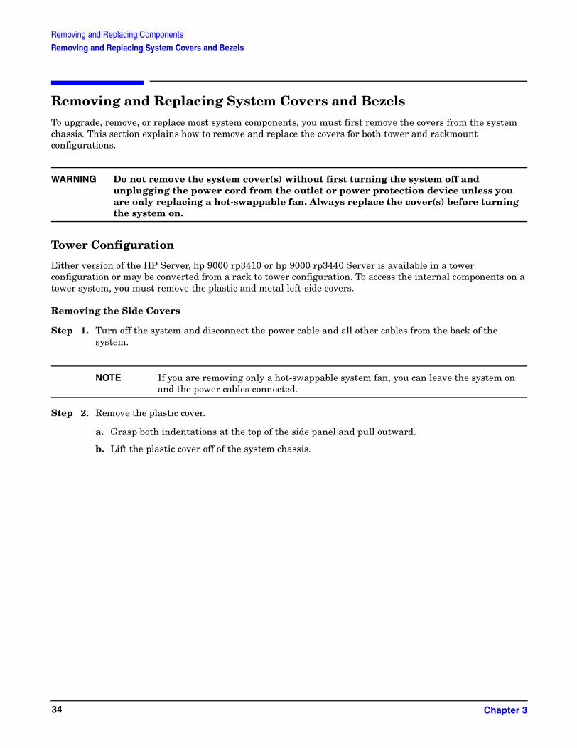
Removing and Replacing System Covers and BezelsTo upgrade, remove, or replace most system components, you must first remove the covers from the system chassis. This section explains how to remove and replace the covers for both tower and rackmount configurations.
WARNING Do not remove the system cover(s) without first turning the system off and unplugging the power cord from the outlet or power protection device unless you are only replacing a hot-swappable fan. Always replace the cover(s) before turning the system on.
Tower Configuration
Either version of the HP Server, hp 9000 rp3410 or hp 9000 rp3440 Server is available in a tower configuration or may be converted from a rack to tower configuration. To access the internal components on a tower system, you must remove the plastic and metal left-side covers.
Removing the Side Covers
Step 1. Turn off the system and disconnect the power cable and all other cables from the back of the system.
NOTE If you are removing only a hot-swappable system fan, you can leave the system on and the power cables connected.
Step 2. Remove the plastic cover.
a. Grasp both indentations at the top of the side panel and pull outward.
b. Lift the plastic cover off of the system chassis.
Chapter 334

Removing and Replacing ComponentsRemoving and Replacing System Covers and Bezels
Figure 3-3Removing the Plastic Cover
Step 3. Remove the metal cover.
Figure 3-4Removing the Metal Cover
a. Turn the top cover lock keyswitch to the unlocked position.
b. Rotate the blue release handle to release the latch.
c. Slide the cover toward the back of the chassis, then lift it off.
Chapter 3 35

Removing and Replacing ComponentsRemoving and Replacing System Covers and Bezels
CAUTION The HP Server depends on the access panels being closed for proper cooling of internal components. Operating the system with the side cover removed can cause the system to quickly overheat.
Replacing the Side Covers
Step 1. Replace the metal cover:
CAUTION Secure any wires or cables in your system so they do not get cut or interfere with the replacement of the cover.
a. Align the front edge of the metal cover with the alignment mark on the optical drive bay.
Figure 3-5Metal Cover Alignment Mark
b. Place the metal cover on the chassis and slide it toward the front of the system until the blue release lever snaps in place.
To replace cover,align front edge herethen slide forward
Chapter 336

Removing and Replacing ComponentsRemoving and Replacing System Covers and Bezels
Figure 3-6Replacing the Metal Cover
Step 2. Replace the plastic cover:
a. Align the cover’s mounting holes with the matching tabs on the system chassis.
b. Close the cover until it snaps onto the system chassis.
Figure 3-7Replacing the Plastic Cover
Chapter 3 37

Removing and Replacing ComponentsRemoving and Replacing System Covers and Bezels
Removing and Replacing the Rackmount Front Bezel
You must remove the front bezel from the chassis to remove or replace the power supplies or the optical drive.
Figure 3-8 Front Bezel
Removing the Front Bezel
To remove the front bezel parts, perform the following steps:
Step 1. Press in on the retaining clips located on the right-side of the front panel.
Step 2. Firmly grasp the finger grip at the top of the bezel and pull forward until the bezel snaps open.
Step 3. Lift the bezel off of the chassis.
Replacing the Front Bezel
To replace the front bezel parts, perform the following steps:
Step 1. Insert the bezel’s latches into the matching slots on the system chassis.
Step 2. Close the bezel and push toward the front of the system until it locks into place.
Chapter 338

Removing and Replacing ComponentsRemoving and Replacing System Covers and Bezels
Figure 3-9 Aligning the Tower Front Bezel
Rack-Mount System
To access the internal components on a rack-mounted system, pull the system out on the rail guides and remove the metal cover.
Accessing a Rack Mounted Server
The hp 9000 rp3410 and rp3440 Servers are designed to be rack mounted. The following procedure explains how to gain access to a server that is mounted in an approved rack. For rack installation instructions, review the document titled Installation Guide, Mid-Weight Slide Kit, 5065-7291.
WARNING Ensure that all anti-tip features (front and rear anti-tip feet installed; adequate ballast properly placed, etc.) are employed prior to extending the server.
Extend the Server from the Rack
NOTE Ensure that there is enough area (approximately 1.5 meters [4.5 ft.]) to fully extend the server out the front and work on it.
To extend the server from the rack, perform the following steps:
Step 1. Turn off the system and disconnect the power cable and all other cables from the back of the system.
Chapter 3 39
Removing and Replacing ComponentsRemoving and Replacing System Covers and Bezels
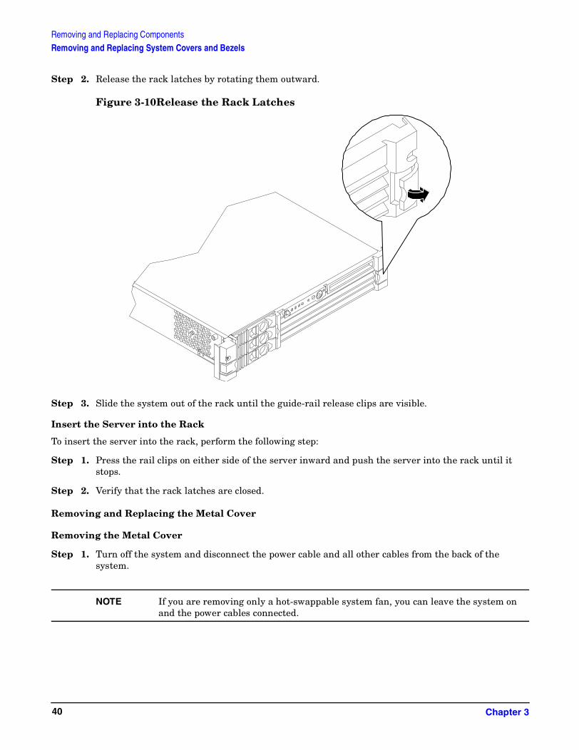
Step 2. Release the rack latches by rotating them outward.
Figure 3-10Release the Rack Latches
Step 3. Slide the system out of the rack until the guide-rail release clips are visible.
Insert the Server into the Rack
To insert the server into the rack, perform the following step:
Step 1. Press the rail clips on either side of the server inward and push the server into the rack until it stops.
Step 2. Verify that the rack latches are closed.
Removing and Replacing the Metal Cover
Removing the Metal Cover
Step 1. Turn off the system and disconnect the power cable and all other cables from the back of the system.
NOTE If you are removing only a hot-swappable system fan, you can leave the system on and the power cables connected.
Chapter 340

Removing and Replacing ComponentsRemoving and Replacing System Covers and Bezels
Step 2. Ensure the top cover lock keyswitch is in the unlocked position. Rotate the blue release lever toward the back of the system and slide the cover toward the back of the system.
Figure 3-11Removing and Replacing the Metal Cover
Step 3. Lift the cover off the system chassis.
Replacing the Cover
CAUTION Secure any wires or cables in your system so they will not get cut or interfere with the replacement of the cover.
Step 1. Align the front edge of the cover with the alignment mark on the optical drive bay.
Chapter 3 41

Removing and Replacing ComponentsRemoving and Replacing System Covers and Bezels
Figure 3-12Aligning the Metal Cover
Step 2. Grasp the blue release lever and slide the cover toward the front of the system until the lever snaps into place.
Figure 3-13Closing the Metal Cover
Step 3. Slide the system into the rack enclosure and reconnect the power cables.
Removing and Replacing the Front Bezel
You must remove the front bezel from the chassis to remove or replace the power supplies or the optical drive.
To replace cover,align front edge herethen slide forward
Chapter 342

Removing and Replacing ComponentsRemoving and Replacing System Covers and Bezels
Removing the Front Bezel
Step 1. Press in on the retaining clips located on the right-side of the front panel.
Figure 3-14Front Bezel Retaining Clip
Step 2. Rotate the front panel outward and lift it off the system chassis.
Replacing the Front Bezel
Step 1. Insert the bezel latches into the matching slots on the system chassis.
Step 2. Close the bezel and push toward the front of the system until it locks into place.
Chapter 3 43

Removing and Replacing ComponentsRemoving and Replacing System Covers and Bezels
Figure 3-15Replacing the Front Bezel
Chapter 344
Removing and Replacing ComponentsRemoving and Replacing Hot-swap and Hot-plug Devices
Removing and Replacing Hot-swap and Hot-plug DevicesThe hp 9000 rp3410 and hp 9000 rp3440 Server have hard disk drives that are hot-pluggable and power supplies and fans that are hot-swappable. This section explains how to swap the following devices while the system is running:
• System fans
• Power supplies
• Hard drives
Removing and Replacing System Fans
There are four system fans to keep the system cool when it is running. The system fans are hot-swappable, allowing you to replace a fan while the system is running.
CAUTION When the system is running, the metal cover must be replaced within five minutes to prevent components from overheating.
Removing a System Fan
Step 1. Remove the system cover(s).
Step 2. Remove the fan.
a. To remove fan 1A, 1B, 2 or 3 from a rack-mounted system, or fan 3 from a tower system, grasp the appropriate fan and lift it out of the fan socket.
Chapter 3 45

Removing and Replacing ComponentsRemoving and Replacing Hot-swap and Hot-plug Devices
Figure 3-16Fan 1A or Fan 1B Removal
Figure 3-17Fan 2 Removal
Fan 1A
Fan 1B
Fan 2
Chapter 346

Removing and Replacing ComponentsRemoving and Replacing Hot-swap and Hot-plug Devices
Figure 3-18Fan 3 Removal
Replacing a System Fan
Step 1. Grasp the replacement fan module and insert it into its fan socket.
CAUTION Replace the metal cover within four minutes to prevent damage to the system components.
Step 2. Verify the fan replacement and operation by using the system utilities. (Refer to the Utilities chapter of the hp9000 rp3410 and rp3440 Operations Guide for additional information.)
• Use the MP commands to verify operation
• Use the BCH commands to verify operation
Removing and Replacing the Power Supply
The power supplies in the HP Server are hot-swappable, that is if one power supply stops working or exhibits voltage problems, the remaining supply can support the system until the failed unit is replaced. A power supply can be removed and replaced without turning off the system on systems with two power supplies.
CAUTION Before removing a power supply, make sure the second power supply is functioning properly. The two green LEDs inside the supply must both be illuminated on the second supply before the failed power supply can be safely removed.
Removing the Power Supply
To remove the power supply, perform the following steps:
Fan 3
Chapter 3 47
Removing and Replacing ComponentsRemoving and Replacing Hot-swap and Hot-plug Devices
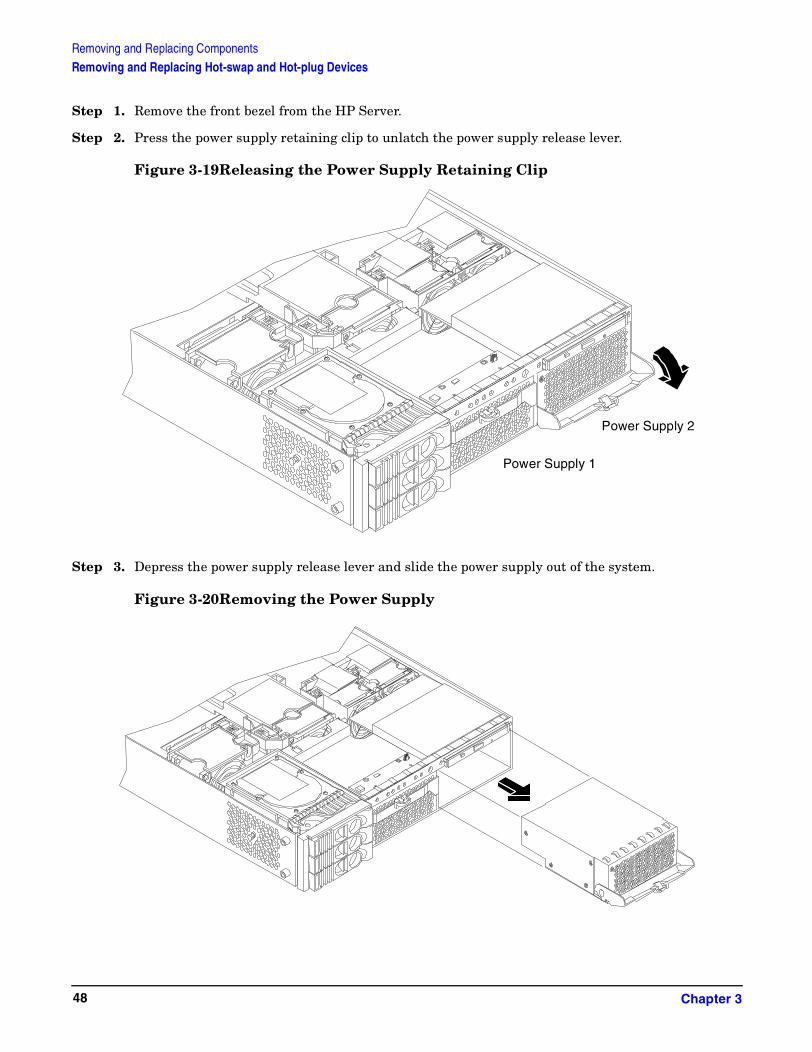
Step 1. Remove the front bezel from the HP Server.
Step 2. Press the power supply retaining clip to unlatch the power supply release lever.
Figure 3-19Releasing the Power Supply Retaining Clip
Step 3. Depress the power supply release lever and slide the power supply out of the system.
Figure 3-20Removing the Power Supply
Power Supply 1
Power Supply 2
Chapter 348
Removing and Replacing ComponentsRemoving and Replacing Hot-swap and Hot-plug Devices
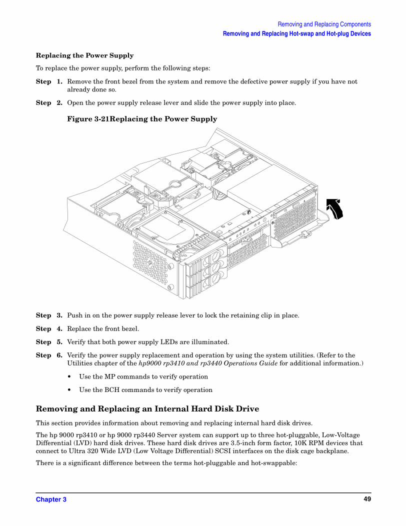
Replacing the Power Supply
To replace the power supply, perform the following steps:
Step 1. Remove the front bezel from the system and remove the defective power supply if you have not already done so.
Step 2. Open the power supply release lever and slide the power supply into place.
Figure 3-21Replacing the Power Supply
Step 3. Push in on the power supply release lever to lock the retaining clip in place.
Step 4. Replace the front bezel.
Step 5. Verify that both power supply LEDs are illuminated.
Step 6. Verify the power supply replacement and operation by using the system utilities. (Refer to the Utilities chapter of the hp9000 rp3410 and rp3440 Operations Guide for additional information.)
• Use the MP commands to verify operation
• Use the BCH commands to verify operation
Removing and Replacing an Internal Hard Disk Drive
This section provides information about removing and replacing internal hard disk drives.
The hp 9000 rp3410 or hp 9000 rp3440 Server system can support up to three hot-pluggable, Low-Voltage Differential (LVD) hard disk drives. These hard disk drives are 3.5-inch form factor, 10K RPM devices that connect to Ultra 320 Wide LVD (Low Voltage Differential) SCSI interfaces on the disk cage backplane.
There is a significant difference between the terms hot-pluggable and hot-swappable:
Chapter 3 49

Removing and Replacing ComponentsRemoving and Replacing Hot-swap and Hot-plug Devices
• Hot-swapping happens at the device level; that is, a hot-swappable device manages insertion/removal on its own without assistance from operating system commands
• The hot-plug process allows you to replace a defective disk drive in a high-availability system while it is running
CAUTION The disk drives in the hp9000 rp3410 and hp 9000 rp3440 Server are not hot-swappable; they are merely hot-pluggable. A manual software procedure must be done in order to safely remove or insert disk drives while the system is running. To avoid damage to the hard drives:
• Refer to the documentation provided with the drive for additional details on inserting/removing a disk drive
• Refer to your OS documentation for instructions on preparing the OS for inserting/removing a hard drive
Removing a Hard Disk Drive
To remove a hard disk drive, perform the following steps:
Step 1. If the server is powered on and the OS is running, prepare the OS to have the disk drive removed. Shut down the OS. Refer to your OS documentation for instructions on preparing the OS for removing and inserting hard drives.
Step 2. If you have locked your hard drives, you must unlock them before removing or replacing a drive:
a. Remove the cover(s).
b. Press down on the unlock lever to unlock the drive.
CAUTION If you try to remove a hard disk drive without unlocking it from the system, you will damage the hard drive bay.
Chapter 350

Removing and Replacing ComponentsRemoving and Replacing Hot-swap and Hot-plug Devices
Figure 3-22Unlocking the Disk Drive
Step 3. Squeeze inward on the colored release clip on the hard drive release lever.
Figure 3-23Releasing the Disk Drive
Step 4. Pull outward on the release lever to remove the drive from the system.
Chapter 3 51

Removing and Replacing ComponentsRemoving and Replacing Hot-swap and Hot-plug Devices
Figure 3-24Removing the Disk Drive
Replacing a Hard Disk Drive
To install or replace a hard disk drive, perform the following steps:
Step 1. If the server is powered on and the OS is running, prepare the OS to have the disk drive removed. Shut down the OS. Refer to your OS documentation for instructions on preparing the OS for removing and inserting hard drives.
Step 2. Insert the hard disk drive into the drive bay from which you removed the drive and push inward on the release lever until the drive no longer slides forward. You must leave the release lever in the open position, as shown, when you push the drive into the system.
Chapter 352
Removing and Replacing ComponentsRemoving and Replacing Hot-swap and Hot-plug Devices
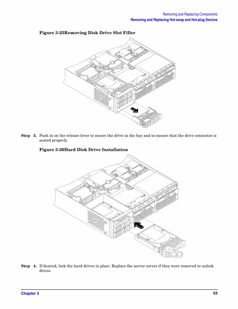
Figure 3-25Removing Disk Drive Slot Filler
Step 3. Push in on the release lever to secure the drive in the bay and to ensure that the drive connector is seated properly.
Figure 3-26Hard Disk Drive Installation
Step 4. If desired, lock the hard drives in place. Replace the server covers if they were removed to unlock drives.
Chapter 3 53

Removing and Replacing ComponentsRemoving and Replacing Hot-swap and Hot-plug Devices
Step 5. Verify the drive replacement and operation by using the system utilities. (Refer to the Utilities chapter of the hp9000 rp3410 and rp3440 Operations Guide for additional information.)
• Use the MP commands to verify operation
• Use the BCH commands to verify operation
• Use diagnostics provided by the ODE to exercise the newly installed module
Step 6. Reset the system to the EFI Boot Maintenance Menu to rescan the hard drives.
Chapter 354

Removing and Replacing ComponentsRemoving and Replacing Internal Components
Removing and Replacing Internal ComponentsTo upgrade, remove, or replace most system components, you must first remove the covers from the system chassis.
WARNING Do not remove the system cover(s) without first turning the system off and unplugging the power cord unless you are only replacing a hot-swappable system fan. Always replace the cover(s) before turning the server on.
Removing and Replacing Airflow Guides
The system has the following airflow guides:
• The processor airflow guide ensures that the proper volume of air for cooling the processor module power pods, processor module(s), and voltage regulator module(s) flows over these components.
You must remove the processor airflow guide:
• If it is damaged to the point that airflow across the processor module(s) is restricted
• To access components under the airflow guide
• The memory airflow guide ensures that the proper volume of air flows over the memory DIMMs to cool them
You must remove the memory airflow guide:
• If it is damaged to the point that airflow across the memory DIMMs is restricted
• To access memory DIMMs and sockets
NOTE Air flows through the system from front to back.
Chapter 3 55

Removing and Replacing ComponentsRemoving and Replacing Internal Components
Figure 3-27 Airflow Guides Locations
Removing and Replacing the Memory Airflow Guide
Removing the Memory Airflow Guide
Step 1. Turn off the system, disconnect all power cables and remove the cover(s).
Step 2. Grasp the memory airflow guide and lift it out of the system.
Figure 3-28Removing the Memory Airflow Guide
Processor Airflow GuideMemory Airflow Guide
Chapter 356

Removing and Replacing ComponentsRemoving and Replacing Internal Components
Replacing the Memory Airflow Guide
Step 1. Align the guides on both sides of the airflow guide with the slots on the chassis.
Step 2. Insert the memory airflow guide in the slots.
Step 3. Replace the cover(s) and reconnect all of the power cables.
Removing and Replacing the Processor Airflow Guide
Removing the Processor Airflow Guide
Step 1. Turn off the system, disconnect all power and external cables and remove the system cover(s).
Step 2. Remove the IDE cable and power module cables from the processor airflow guide cable clips.
Step 3. Remove the main portion of the airflow guide:
a. Hold the guide using the opening on top of the guide.
b. At the same time, grasp the back end of the airflow guide and lift the guide out of the system.
Figure 3-29Removing the Processor Airflow Guide
Step 4. Remove the front portion of the airflow guide:
a. Remove system fans 1A and 1B.
b. Rotate the clip clockwise to release the latch.
Chapter 3 57

Removing and Replacing ComponentsRemoving and Replacing Internal Components
Figure 3-30Open the Release Clip
Step 5. Disconnect the power cable connected to the guide from the system board.
Step 6. Lift the front portion of the airflow guide out of the system.
Figure 3-31Remove the Front Airflow Guide
Chapter 358

Removing and Replacing ComponentsRemoving and Replacing Internal Components
Replacing the Processor Airflow Guide
Step 1. Replace the front portion of the airflow guide:
a. Align the release latch of the front half of the airflow guide over the release latch post and snap it in place.
b. Connect power connector on the front portion of the guide to the connector on the system board.
c. Replace system fans 1A and 1B.
Step 2. Replace the main portion of the airflow guide:
a. Hold the opening on top of the processor airflow guide.
b. At the same time, grasp the back end of the airflow guide and insert the airflow guide into the system.
c. Connect the power module cable and place the power and IDE cables in the cable clips.
d. Insert the two airflow guide retaining tabs into the two slots on the front half of the airflow guide.
Step 3. Replace the system cover(s). Reconnect cables.
Removing and Replacing System Memory
Your system has 12 memory sockets for installing DDR SDRAM memory modules. These memory modules can either be 256 MB, 512 MB, 1 GB or 2 GB. The system supports combinations from 512 MB up to 6 GB (hp9000 rp 3410) or up to 24 GB (hp9000 rp3440).
System memory DIMMs are located on the system board.
WARNING Ensure that the system is powered-down and all power sources have been disconnected from the server prior to removing or replacing system memory.
Voltages are present at various locations within the server whenever an AC power source is connected. This voltage is present even when the main power switch is in the off position.
Failure to observe this warning could result in personal injury or damage to equipment.
CAUTION Observe all ESD safety precautions before attempting this procedure. Failure to follow ESD safety precautions could result in damage to the server.
Supported DIMM Sizes
Supported DIMM sizes are 256 MB and 512 MB (hp9000 rp3410) and 256 MB, 512 MB, 1 GB, and 2 GB (hp9000 rp3440). Dissimilar DIMM sizes may be used across the entire system board but all DIMMs in each quad must be identical.
Chapter 3 59

Removing and Replacing ComponentsRemoving and Replacing Internal Components
Figure 3-32 DIMM Slot Identification
Removing System Memory
To remove system memory, perform the following steps:
Step 1. Turn off the system, disconnect power, LAN and telecommunications cables, and remove the cover(s).
Step 2. Identify the DIMM to be removed and push the appropriate extraction levers found on either side of the DIMM slot outward to the open position. The DIMM will eject from the slot.
Step 3. Remove the DIMM from the socket. If the removed memory is functional, store it in a static-free container for future use.
Rear
Front
Pair 5 (4A & 4B)
Pair 2 (1A&1B)
1A
1B
3A
3B
Pair 4 (3A&3B)
Pair 1 (0A&0B)
2A0B 2B
0A
Cell 1
Cell 0
4B
5B
5A
4A
Pair 3 (2A&2B)
Pair 6 (5A&5B)
Quad 1 = Pair 1 & Pair 2
Quad 2 = Pair 3 & Pair 4
Quad 3 = Pair 5 & Pair 6
Chapter 360

Removing and Replacing ComponentsRemoving and Replacing Internal Components
Installing System Memory
Memory modules must be loaded in the correct order:
• In the hp 9000 rp3410 Server, the first four DIMMs must be installed as ordered pairs of equal size. The DIMM in socket 0A must match the DIMM in socket 0B. If a second pair is added (sockets 1A and 1B), the DIMMs must match the DIMMs in sockets 0A and 0B. Additional DIMMs (DIMM sockets 5 through 12) must be installed as quads (groups of four—two matched pairs). This requirement is summarized as:
• 0A and 0B must be identical pair
• 1A and 1B must be identical to the pair in sockets 0A and 0B
• 2A, 2B and 3A, 3B must be identical quad (2 pairs)
• 4A, 4B and 5A, 5B must be identical quad (2 pairs)
• In the hp 9000 rp3440 Server, DIMMs must be installed in matched quads. Two matched memory card pairs of equal size (that is, four identical DIMMs) must be installed, one pair per memory cell, as listed below:
• 0A, 0B and 1A, 1B must be identical quad (2 pairs)
• 2A, 2B and 3A, 3B must be identical quad (2 pairs)
• 4A, 4B and 5A, 5B must be identical quad (2 pairs)
NOTE DIMMs match if they have the same HP part number.
Module sizes can be mixed, as long as DIMMs in each quad match. For example:
• On hp 9000 rp3410 Server, it is acceptable to load four 256 MB DIMMs in sockets 0A, 0B, 1A, and 1B and four 512 MB DIMMs in sockets 2A, 2B, 3A, and 3B
• On hp 9000 rp3440 Servers, it is acceptable to load a quad of 256 MB DIMMs in sockets 0A, 0B, 1A and 1B, and a quad of 1 GB DIMMs in sockets 2A, 2B, 3A and 3B
To install DIMMs, perform the following steps:
Step 1. Turn off the system, disconnect all cables, and remove the system cover(s).
CAUTION To ensure that memory modules are not damaged during removal or installation, power off the server and unplug the power cord from the AC power outlet. Wait until the LED on the back of the power supply turns off before removing or installing memory.
Step 2. Holding the memory module by its left and right edges, insert the module into the socket.
The memory modules are keyed and can only be inserted in one direction. When the module is correctly seated, the retainer clips will return to their fully upright position. Snap the clips firmly into place to ensure that the DIMMs are seated properly.
Step 3. Gently and evenly push on each side of the DIMM until it seats in the socket. Ensure the extraction levers are in the closed position.
Step 4. Replace the system cover(s), reconnect all cables and turn on the system.
Chapter 3 61

Removing and Replacing ComponentsRemoving and Replacing Internal Components
Step 5. Verify the memory replacement and operation by using the system utilities. (Refer to the Utilities chapter of the hp9000 rp3410 and rp3440 Operations Guide for additional information.)
• Use the MP commands to verify operation
• Use the BCH commands to verify operation
• Use diagnostics provided by the ODE to exercise the newly installed memory
Figure 3-33 Inserting DIMM into Slot
Removing and Replacing a Processor Module
This section provides information about installing processor modules. The processor modules are located on the system board which is accessible by removing the system cover.
WARNING Ensure that the system is powered-down and all power sources have been disconnected from the server prior to removing or replacing a processor module.
Voltages are present at various locations within the server whenever an AC power source is connected. This voltage is present even when the main power switch is in the off position.
Failure to observe this warning could result in personal injury or damage to equipment.
CAUTION Failure to properly complete the steps in this procedure will result in erratic system behavior or system failure. For assistance with this procedure contact your local HP Authorized Service Provider.
Observe all ESD safety precautions before attempting this procedure. Failure to follow ESD safety precautions could result in damage to the server.
Chapter 362

Removing and Replacing ComponentsRemoving and Replacing Internal Components
NOTE Processor tool kit, HP P/N 5069-5441 is required for removal and installation of a processor module.
Removing a Processor Module
To remove a processor module, perform the following steps:
Step 1. Turn off the system and disconnect all cables.
Step 2. Remove the cover. (Refer to “Removing and Replacing the Metal Cover” on page 40 for instructions.)
Step 3. Remove the processor airflow guide and cables.
Step 4. Disconnect the power pod cable from the power connector on the system board.
Figure 3-34Disconnect Power Pod Cable
Chapter 3 63
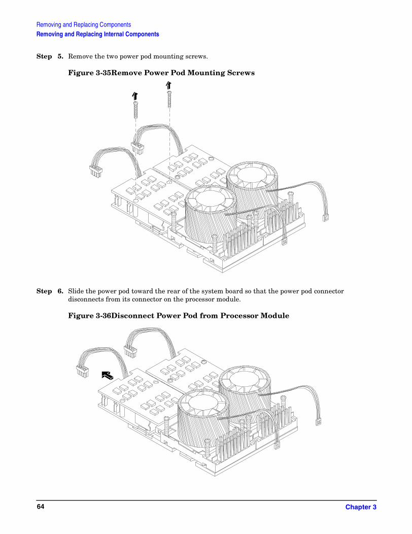
Removing and Replacing ComponentsRemoving and Replacing Internal Components
Step 5. Remove the two power pod mounting screws.
Figure 3-35Remove Power Pod Mounting Screws
Step 6. Slide the power pod toward the rear of the system board so that the power pod connector disconnects from its connector on the processor module.
Figure 3-36Disconnect Power Pod from Processor Module
Chapter 364

Removing and Replacing ComponentsRemoving and Replacing Internal Components
Step 7. Lift the power pod up and out of the chassis. Place the power pod into an anti-static container.
Figure 3-37Remove Power Pod
Chapter 3 65

Removing and Replacing ComponentsRemoving and Replacing Internal Components
Step 8. Disconnect the processor module turbo fan power cable.
Figure 3-38Disconnect the Turbo Fan Cable
Step 9. Release the four heatsink captive screws on the processor module heat sink.
Figure 3-39Release Heatsink Captive Screws
CPU Install Tool(Torx T15)
Chapter 366
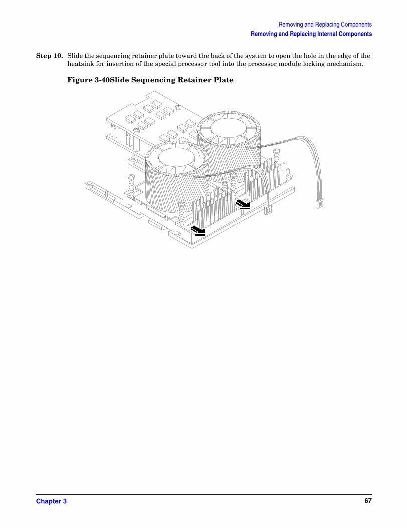
Removing and Replacing ComponentsRemoving and Replacing Internal Components
Step 10. Slide the sequencing retainer plate toward the back of the system to open the hole in the edge of the heatsink for insertion of the special processor tool into the processor module locking mechanism.
Figure 3-40Slide Sequencing Retainer Plate
Chapter 3 67
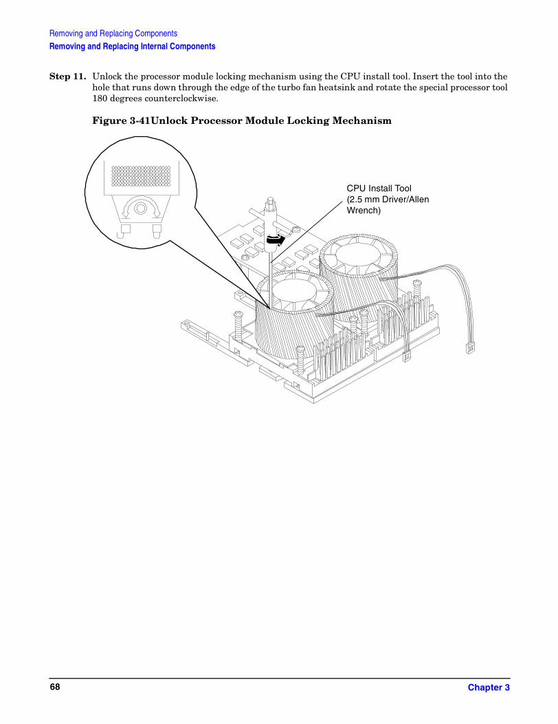
Removing and Replacing ComponentsRemoving and Replacing Internal Components
Step 11. Unlock the processor module locking mechanism using the CPU install tool. Insert the tool into the hole that runs down through the edge of the turbo fan heatsink and rotate the special processor tool 180 degrees counterclockwise.
Figure 3-41Unlock Processor Module Locking Mechanism
CPU Install Tool (2.5 mm Driver/Allen Wrench)
Chapter 368

Removing and Replacing ComponentsRemoving and Replacing Internal Components
Step 12. Lift the processor module and the turbo fan assembly up and out of the chassis. Place the processor module into an anti-static container.
Figure 3-42Remove Processor Module
Chapter 3 69

Removing and Replacing ComponentsRemoving and Replacing Internal Components
Figure 3-43 Processor Module Removal/Replacement
Replacing a Processor Module
Processor modules are located on the system board. The system board can support either one or two processor modules. CPU 0 is located to the right of the system board and CPU 1 (when installed) is located on the left of the system board next to the bridge assembly. In a single CPU configuration, the single processor module must be installed in CPU 0 slot.
Each processor module has an associated power pod that is required by the processor module.
CAUTION Do not modify the settings of the DIP switches located on the system board. These switches are for factory use. Failure to observe this caution will result in system failure.
Step 1. Turn off the system and disconnect all cables.
Step 2. Remove the cover. (Refer to “Removing and Replacing the Metal Cover” on page 40 for instructions.)
Step 3. If you are replacing a processor module, remove the old processor module as described in the previous procedure.
CPU 0
CPU 1
Power Pod CPU 0
Power Pod CPU 1
Chapter 370

Removing and Replacing ComponentsRemoving and Replacing Internal Components
Step 4. Unlock the processor module locking mechanism using the CPU install tool. Insert the tool into the hole that runs down through the edge of the heatsink and rotate the special processor tool 180 degrees counterclockwise. Verify that the processor module socket locking mechanism is rotated into the unlocked position.
Figure 3-44Unlocking the Processor Module Locking Mechanism
Step 5. Use the four locator posts on the heatsink and the turbo fan power cable to properly align the fan and processor module on the system board. The four locator posts will fit in locator holes on the system board processor module mount. The turbo fan power cable must be positioned so that it is located on the side of the heatsink that faces the front of the system.
Figure 3-45Aligning the Processor Module
CPU Install Tool(2.5 mm Driver/Allen
Wrench)
Chapter 3 71

Removing and Replacing ComponentsRemoving and Replacing Internal Components
Step 6. Use the special processor tool to lock the processor module in place on the system board. To do this, insert the special processor tool into the hole that runs down the side of the heatsink and rotate it clockwise 180 degrees.
Figure 3-46Locking the Processor Module in Place
Step 7. Slide the sequencing retainer plate toward the front of the system.
Figure 3-47Slide the Sequencing Retainer Plate
CPU Install Tool(2.5 mm Driver/Allen Wrench)
Chapter 372
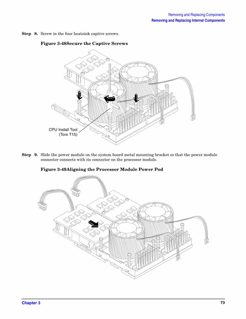
Removing and Replacing ComponentsRemoving and Replacing Internal Components
Step 8. Screw in the four heatsink captive screws.
Figure 3-48Secure the Captive Screws
Step 9. Slide the power module on the system board metal mounting bracket so that the power module connector connects with its connector on the processor module.
Figure 3-49Aligning the Processor Module Power Pod
CPU Install Tool(Torx T15)
Chapter 3 73

Removing and Replacing ComponentsRemoving and Replacing Internal Components
Step 10. Align the two mounting screw holes on the power module with their screw holes on the system board’s metal mounting bracket. Screw in the power module mounting screws.
Figure 3-50Install the Processor Module Power Pod Mounting Screws
Step 11. Replace the processor airflow guide.
Step 12. Connect the power pod cable to the power connector on the system board.
Figure 3-51Connecting the Power Pod Cable
Chapter 374
Removing and Replacing ComponentsRemoving and Replacing Internal Components
Step 13. Replace the cover.
Step 14. Verify the processor replacement and operation by using the system utilities. (Refer to the Utilities chapter of the hp9000 rp3410 and rp3440 Operations Guide for additional information.)
• Use the MP commands to verify operation
• Use the BCH commands to verify operation
• Use diagnostics provided by the ODE to exercise the newly installed processor
Chapter 3 75

Removing and Replacing ComponentsRemoving and Replacing Internal Components
Removing and Replacing the System Battery
Systems with a management processor card have two batteries. Systems with no management processor card have only one battery. The main system battery is located on the system board.
Removing the System Battery
Step 1. Turn off the system and disconnect all cables.
Step 2. Remove the cover. (Refer to “Removing and Replacing the Metal Cover” on page 40 for instructions.)
Step 3. Lift up on the battery and push on the back of it with a flat-head screwdriver to remove the battery from its holder.
CAUTION Only lift the battery high enough to clear the holder. Excessive stress on the battery holder retaining clip may damage the clip.
Figure 3-52Removing the System Battery
Replacing the System Battery
Step 1. Perform system battery removal described above.
Chapter 376
Removing and Replacing ComponentsRemoving and Replacing Internal Components
Step 2. Lift up on the battery holder retaining clip with a flat-head screwdriver and slide the battery into the holder. The positive (+) terminal of the battery faces up.
CAUTION Only lift the battery high enough to clear the holder. Excessive stress on the battery holder retaining clip may damage the clip.
Step 3. Replace the cover.
Step 4. Reconnect all of the power and external cables and turn on the system.
Step 5. Verify the battery replacement and operation by using the system utilities. (Refer to the Utilities chapter of the hp9000 rp3410 and rp3440 Operations Guide for additional information.)
• Use the MP commands to verify operation
• Use the BCH commands to verify operation
Step 6. You may need to reset the system time and date using the BCH time and date commands. Once you have set the time, turn the system off, unplug the power cord, and wait for a minute before turning it back on. Execute the time and date commands again. If the time and date are now correct, you have installed the battery correctly.
Removing and Replacing PCI and Graphics Cards
Accessory cards are installed in a removable PCI cage. This section explains how to access the PCI cage, as well as how to remove and install accessory cards.
Removing the PCI Cage
To remove the PCI cage from the server, perform the following steps:
Step 1. Remove the cover. (Refer to “Removing and Replacing the Metal Cover” on page 40 for instructions.)
Step 2. Lift up on the PCI cage release lever and the back edge of the PCI cage and lift the PCI cage out of the system.
Chapter 3 77

Removing and Replacing ComponentsRemoving and Replacing Internal Components
Figure 3-53Removing the PCI Cage
Step 3. Grasp the PCI cage cover and slide it away from the bulkhead end of the cage, then lift the cover off.
Figure 3-54Removing the PCI Cage Cover
Step 4. Unscrew the bulkhead screw that holds the accessory card in place.
Step 5. The PCI cards are now accessible for removal and replacement.
Chapter 378

Removing and Replacing ComponentsRemoving and Replacing Internal Components
Removing and Replacing PCI Cards
The server may contain up to 4 PCI cards. PCI cards are located in the PCI cage.
The hp 9000 rp3410 provides two 64-bit, 133 MHz PCI-X card sockets and the hp 9000 rp3440 Server provides four 64-bit, 133 MHz PCI-X card sockets.
WARNING Ensure that the system is powered-down and all power sources have been disconnected from the server prior to removing or replacing a PCI card.
Voltages are present at various locations within the server whenever an AC power source is connected. This voltage is present even when the main power switch is in the off position.
Failure to observe this warning could result in personal injury or damage to equipment.
CAUTION Observe all ESD safety precautions before attempting this procedure. Failure to follow ESD safety precautions could result in damage to the server.
Carefully read the following information concerning PCI slot configuration. Inserting a PCI card into a slot that is not configured to accept it, may cause operation failure or the PCI card to operate at less than optimum speed. PCI slots are numbered 1 through 4. See the labels on the rear panel of the chassis for correct PCI slot number identification.
Removing a PCI Card
To remove a PCI card from the server, perform the following steps:
CAUTION Record the location of all PCI cards as they are installed. Depending on the operating system, replacing the PCI card in a different location might cause boot failure.
Step 1. Remove the cover. (Refer to “Removing and Replacing the Metal Cover” on page 40 for instructions.)
Step 2. Perform the procedure for removing the PCI cage described in the previous section.
Step 3. Disconnect any cables that are connected to the PCI card.
Step 4. Grasp the edges of the PCI card being removed and gently rock the card releasing the connector from the PCI backplane connector. Place the removed PCI card in an electrostatic container.
Step 5. Install a PCI slot cover to close the cavity left by the removal of the PCI card. This will maintain the proper airflow within the chassis.
Chapter 3 79

Removing and Replacing ComponentsRemoving and Replacing Internal Components
Figure 3-55Installing a PCI Slot Cover
Replacing a PCI or Graphics Card
Step 1. Remove the cover. (Refer to “Removing and Replacing the Metal Cover” on page 40 for instructions.)
Step 2. Remove the PCI cage.
Step 3. Open the PCI cage as described in the previous section.
Step 4. Grasp the edges of the PCI card to be installed and gently press the card into the PCI backplane connector.
Figure 3-56Installing a PCI Card
Chapter 380

Removing and Replacing ComponentsRemoving and Replacing Internal Components
Step 5. Connect any cables that are required by the PCI card.
Step 6. Reinstall the PCI cage.
Step 7. Replace the cover. (Refer to “Removing and Replacing the Metal Cover” on page 40 for instructions.)
Step 8. Verify the PCI card replacement and operation by using the system utilities. (Refer to the Utilities chapter of the hp9000 rp3410 and rp3440 Operations Guide for additional information.)
• Use the MP commands to verify operation
• Use the BCH commands to verify operation
Removing and Replacing the PCI Backplane
The hp 9000 rp 3410 and the hp 9000 rp3440 Server system backplane is called the PCI backplane and provides four PCI card sockets. The removal process is the same for both.
Removing the PCI Backplane
Step 1. Remove all accessory and graphics cards.
Step 2. Unscrew the backplane mounting screws and slide the backplane board toward the bulkhead end of the PCI cage. This unlocks the backplane from its standoffs.
Step 3. Lift the backplane over the top of the standoffs and slide it out of the cage.
Figure 3-57Removing the PCI Backplane
Chapter 3 81

Removing and Replacing ComponentsRemoving and Replacing Internal Components
Replacing the PCI Backplane
Step 1. Place the backplane in the cage by aligning the cage standoffs with the holes on the backplane and slide it into place.
Step 2. Secure the PCI backplane by screwing in its mounting screws.
Figure 3-58Replacing the PCI Backplane
Step 3. Replace any accessory and graphics cards.
Step 4. Verify the backplane replacement and operation by using the system utilities. (Refer to the Utilities chapter of the hp9000 rp3410 and rp3440 Operations Guide for additional information.)
• Use the MP commands to verify operation
• Use the BCH commands to verify operation
Removing and Replacing a Removable Media Drive
The removable media drive is located behind the Front bezel.
WARNING Ensure that the system is powered-down and all power sources have been disconnected from the server prior to removing or replacing a removable media drive.
Voltages are present at various locations within the server whenever an AC power source is connected. This voltage is present even when the main power switch is in the off position.
Failure to observe this warning could result in personal injury or damage to equipment.
Chapter 382

Removing and Replacing ComponentsRemoving and Replacing Internal Components
CAUTION Observe all ESD safety precautions before attempting this procedure. Failure to follow ESD safety precautions could result in damage to the server. Failure to properly complete the steps in this procedure will result in erratic system behavior or system failure. For assistance with this procedure contact your local HP Authorized Service Provider.
Figure 3-59 Removable Media Drive Removal/Replacement
Removing a Removable Media Drive
To remove a Removable Media Drive, perform the following steps:
Step 1. Turn off the system and disconnect all cables.
Step 2. Remove the cover. (Refer to “Removing and Replacing the Metal Cover” on page 40 for instructions.)
Step 3. Disconnect the IDE cable from the back of the drive.
Step 4. Grasp the front of the DVD drive and squeeze in on the locking tab to release the drive.
Step 5. Pull the drive straight out to remove it from the chassis.
Replacing a Removable Media Drive
To replace the removable DVD drive, perform the following steps:
Step 1. If a removable media drive has not previously been installed in the server, the drive slot will be covered with a DVD drive filler. Remove the DVD drive filler.
Chapter 3 83

Removing and Replacing ComponentsRemoving and Replacing Internal Components
Step 2. Slide the replacement drive into the drive bay until it stops sliding and the retaining clips on both sides of the drive snap into place.
Step 3. Connect the IDE cable on the back of the drive.
Step 4. Replace the cover.
Step 5. Reconnect the power and external cables and turn on the system.
Step 6. Verify the drive replacement and operation by using the system utilities. (Refer to the Utilities chapter of the hp9000 rp3410 and rp3440 Operations Guide for additional information.)
• Use the MP commands to verify operation
• Use the BCH commands to verify operation
• Use diagnostics provided by the ODE to exercise the newly installed module
Removing and Replacing the Management Processor Card
The management processor is an independent support system for the server. It provides a way to connect to a server and perform administration or monitoring tasks for the server hardware.
Removing the Management Processor Card
Step 1. Turn off the system, disconnect all power and external cables and remove the system cover(s).
Step 2. Record the network settings from your management processor card before beginning this task.
Step 3. Unscrew the two mounting screws that connect the management processor card to the internal chassis post and the two external mounting screws that are located on both sides of the 25-pin serial connector.
Chapter 384
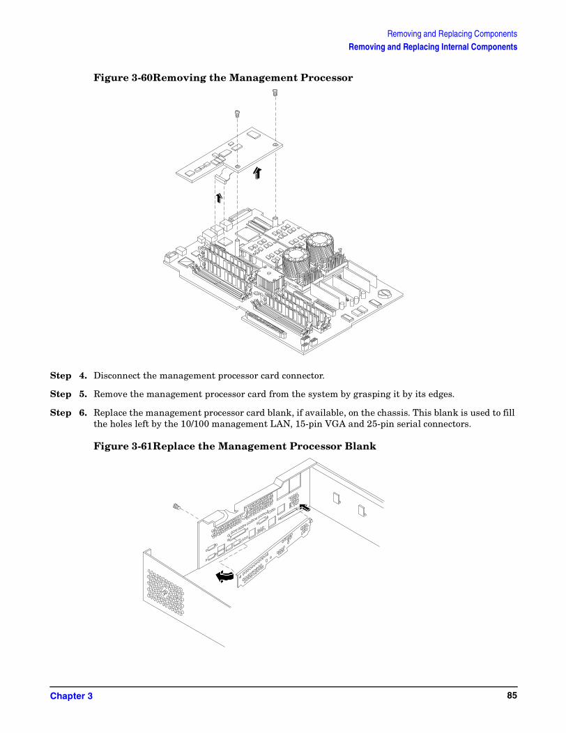
Removing and Replacing ComponentsRemoving and Replacing Internal Components
Figure 3-60Removing the Management Processor
Step 4. Disconnect the management processor card connector.
Step 5. Remove the management processor card from the system by grasping it by its edges.
Step 6. Replace the management processor card blank, if available, on the chassis. This blank is used to fill the holes left by the 10/100 management LAN, 15-pin VGA and 25-pin serial connectors.
Figure 3-61Replace the Management Processor Blank
Chapter 3 85

Removing and Replacing ComponentsRemoving and Replacing Internal Components
Step 7. Push the management processor card blank against the inside of the chassis and screw in the blank’s mounting screw on the external connector side of the system’s chassis.
Step 8. Replace the cover (s) and reconnect the power and external cables.
Replacing the Management Processor Card
Step 1. Turn off the system, disconnect all power and external cables and remove the system cover(s).
Step 2. If you are installing a new card, remove the management processor card blank.
Step 3. Unscrew the mounting screw for the management processor card blank, located on the external connector side of the system chassis.
Step 4. Remove the blank retaining tab out of its socket on the system chassis and remove the blank from the system.
Step 5. Insert the management processor card in the system.
Step 6. Grasp its edges and place it on the two management processor card posts.
Step 7. Push the 10/100 management LAN, 15-pin VGA and 25-pin serial connectors through their openings on the back of the system.
Step 8. Connect the management processor card:
• Connect the management processor card cable to its connector on the system board
• Screw in the two mounting screws that connect the management processor card to the internal chassis post
• Screw in the two external mounting screws that are located on both sides of the 25-pin serial connector
Step 9. Replace the power connector.
Step 10. Verify the card replacement and operation by using the system utilities. (Refer to the Utilities chapter of the hp9000 rp3410 and rp3440 Operations Guide for additional information.)
• Use the MP commands to verify operation
• Use the BCH commands to verify operation
Removing and Replacing the Management Processor Card Battery
Systems with a management processor card have two batteries. Systems with no management processor card have only one battery. The main system battery is located on the system board. The management processor battery is located on the management processor card.
Removing the Management Processor Card Battery
Step 1. Perform all of the steps described in the procedure for removing the management processor card.
Step 2. The battery for the management processor is located on the bottom of the card.
Step 3. Lift up on the battery and push on the back of it with a flat-head screwdriver to remove the battery from its holder.
Chapter 386

Removing and Replacing ComponentsRemoving and Replacing Internal Components
CAUTION Only lift the battery high enough to clear the holder. Excessive stress on the battery holder retaining clip may damage the clip.
Figure 3-62Removing the Management Processor Battery
Replacing the Management Processor Card Battery
Step 1. Lift up on the battery holder retaining clip with a flat-head screwdriver and slide the battery into the holder. The positive (+) terminal of the battery faces up.
CAUTION Only lift the battery high enough to clear the holder. Excessive stress on the battery holder retaining clip may damage the clip.
Step 2. Perform all of the steps described in the procedure for replacing the management processor card.
Step 3. Verify the battery replacement and operation by using the system utilities. (Refer to the Utilities chapter of the hp9000 rp3410 and rp3440 Operations Guide for additional information.)
• Use the MP commands to verify operation.
• Use the BCH commands to verify operation.
Chapter 3 87
Removing and Replacing ComponentsRemoving and Replacing Internal Components
Removing and Replacing the LED Status Panel
The LED status panel card contains the system LEDs and diagnostic LEDs.
CAUTION Some system settings are saved to the LED status panel. If you are replacing both the LED status panel and the system board, they must be replaced one at a time to avoid loss of system settings. First replace one component, then turn on the system and boot to the EFI prompt. After confirming that the first component has been replaced successfully, shut down the system and replace the second component.
Removing the LED Status Panel
Step 1. Turn off the system, disconnect all power cables, and remove the system cover(s).
Step 2. Disconnect the LED status panel’s controller cable.
Step 3. Unscrew the two LED status panel mounting screws and remove the panel.
Figure 3-63Removing the LED Status Panel
Replacing the LED Status Panel
Step 1. Replace the LED status panel in the system and screw in the two LED status panel mounting screws.
Step 2. Connect the LED status panel controller cable.
Step 3. Replace the system cover(s) and reconnect all power cables. Turn on the system and verify that the system and power LEDs light up.
Chapter 388
Removing and Replacing ComponentsRemoving and Replacing Internal Components
Step 4. Copy a valid UUID to the new status panel.
NOTE If resetting the UUID does not work successfully, contact your HP support representative.
Step 5. Verify the display panel replacement and operation by using the system utilities. (Refer to the Utilities chapter of the hp9000 rp3410 and rp3440 Operations Guide for additional information.)
• Use the MP commands to verify operation
• Use the BCH commands to verify operation
Removing and Replacing the System Board
CAUTION Some system settings are saved to the LED status panel. If you are replacing both the LED status panel and the system board, they must be replaced one at a time to avoid loss of system settings. First replace one component, then turn on the system and boot to the EFI prompt. After confirming that the first component has been replaced successfully, shut down the system and replace the second component.
Removing the System Board
Step 1. Turn off the system, disconnect all power and external cables and remove the system cover(s).
Step 2. Remove these components from the system board:
• Memory (DIMMs)
• Processor airflow guide and processor module(s)
• Management card (if installed)
Step 3. If the system does not have a management card installed, remove the power connector plate.
a. Unscrew the two power connector mounting screws on the back of the system
b. Reach inside the system to remove the power connectors from the socket. The power connectors will still be connected to their cables.
Step 4. Unscrew the six backplane system board mounting screws that connect the system board to the rear of the system chassis.
Chapter 3 89

Removing and Replacing ComponentsRemoving and Replacing Internal Components
Figure 3-64Remove System Board Mounting Screws
Step 5. Disconnect all cables that are connected to the system board. To help with re-assembly, make note of which cables were connected to which connector.
NOTE To access the three power cables near the PCI cage, you must lift up the connector bridge for the PCI cage fan.
Step 6. Unscrew the system board mounting screw. A screw symbol is adjacent to the mounting screw.
Chapter 390
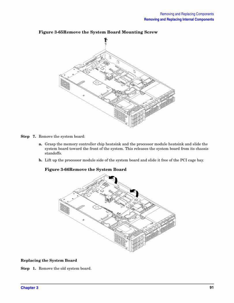
Removing and Replacing ComponentsRemoving and Replacing Internal Components
Figure 3-65Remove the System Board Mounting Screw
Step 7. Remove the system board:
a. Grasp the memory controller chip heatsink and the processor module heatsink and slide the system board toward the front of the system. This releases the system board from its chassis standoffs.
b. Lift up the processor module side of the system board and slide it free of the PCI cage bay.
Figure 3-66Remove the System Board
Replacing the System Board
Step 1. Remove the old system board.
Chapter 3 91

Removing and Replacing ComponentsRemoving and Replacing Internal Components
Step 2. Grasp the new system board by its edges and carefully align it in the system:
a. Angle the board to allow the PCI connector to slide into the PCI cage bay area.
Figure 3-67Slide System Board into Chassis
b. Align the system board keyholes with their standoffs on the chassis.
Chapter 392

Removing and Replacing ComponentsRemoving and Replacing Internal Components
c. Slide the PCI connector posts on the system board into their slots on the system chassis.
Figure 3-68Align the System Board PCI Connector
Chapter 3 93

Removing and Replacing ComponentsRemoving and Replacing Internal Components
Step 3. Slide the system board back toward the rear of the system to secure the system board on its standoffs.
Figure 3-69Slide System Board in Chassis
Chapter 394
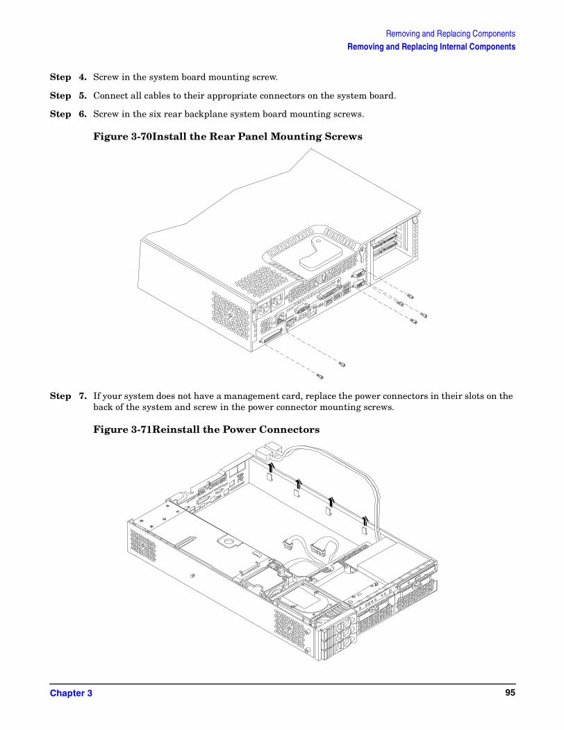
Removing and Replacing ComponentsRemoving and Replacing Internal Components
Step 4. Screw in the system board mounting screw.
Step 5. Connect all cables to their appropriate connectors on the system board.
Step 6. Screw in the six rear backplane system board mounting screws.
Figure 3-70Install the Rear Panel Mounting Screws
Step 7. If your system does not have a management card, replace the power connectors in their slots on the back of the system and screw in the power connector mounting screws.
Figure 3-71Reinstall the Power Connectors
Chapter 3 95

Removing and Replacing ComponentsRemoving and Replacing Internal Components
Step 8. Replace the following system components:
• Management card
• Processor airflow guide
• System fans
• PCI card cage
• Memory
Step 9. Replace the system cover(s), reconnect all of the power and external cables and turn on the system.
Step 10. Verify the system board replacement and operation by using the system utilities. (Refer to the Utilities chapter of the hp9000 rp3410 and rp3440 Operations Guide for additional information.)
• Use the MP commands to verify operation
• Use the SS_UPDATE command to change the model string if necessary
• Use the BCH commands to verify operation
Step 11. Review the system configuration in the EFI shell and reconfigure settings as necessary.
Removing and Replacing the Power Supply Interface Module
The Power Supply Interface (PSI) module supports up to two redundant power supplies.
Removing the Power Supply Interface Module
Step 1. Turn off the system, disconnect all power and external cables, and remove the system cover(s).
Step 2. Remove the system board.
Step 3. Lift the power cables out of their metal holding clips.
Chapter 396

Removing and Replacing ComponentsRemoving and Replacing Internal Components
Figure 3-72Power Cables and Holding Clips
Step 4. Unscrew the PSI mounting screw and remove the PSI module from the system.
Figure 3-73Remove the Mounting Screw
Chapter 3 97

Removing and Replacing ComponentsRemoving and Replacing Internal Components
Figure 3-74Remove the PSI Interface Module
Replacing the Power Supply Interface Module
Step 1. Place the PSI module into the chassis by sliding the module retaining tab into the socket on the hard disk drive bay wall.
Figure 3-75Replacing the Power Supply Interface Module
Chapter 398
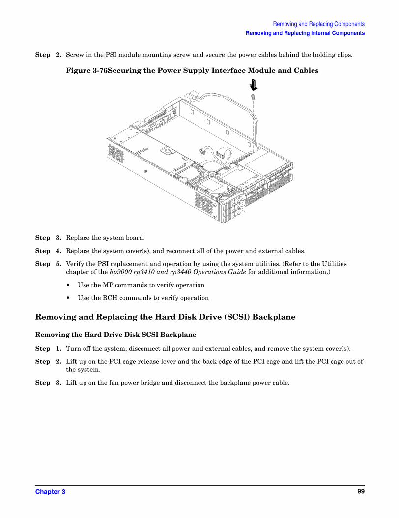
Removing and Replacing ComponentsRemoving and Replacing Internal Components
Step 2. Screw in the PSI module mounting screw and secure the power cables behind the holding clips.
Figure 3-76Securing the Power Supply Interface Module and Cables
Step 3. Replace the system board.
Step 4. Replace the system cover(s), and reconnect all of the power and external cables.
Step 5. Verify the PSI replacement and operation by using the system utilities. (Refer to the Utilities chapter of the hp9000 rp3410 and rp3440 Operations Guide for additional information.)
• Use the MP commands to verify operation
• Use the BCH commands to verify operation
Removing and Replacing the Hard Disk Drive (SCSI) Backplane
Removing the Hard Drive Disk SCSI Backplane
Step 1. Turn off the system, disconnect all power and external cables, and remove the system cover(s).
Step 2. Lift up on the PCI cage release lever and the back edge of the PCI cage and lift the PCI cage out of the system.
Step 3. Lift up on the fan power bridge and disconnect the backplane power cable.
Chapter 3 99

Removing and Replacing ComponentsRemoving and Replacing Internal Components
Figure 3-77Open the Fan Power Bridge
Chapter 3100

Removing and Replacing ComponentsRemoving and Replacing Internal Components
Step 4. Disconnect the SCSI cables and unscrew the backplane mounting screws.
Figure 3-78Disconnect SCSI Cables
Figure 3-79Remove Mounting Screws
Chapter 3 101
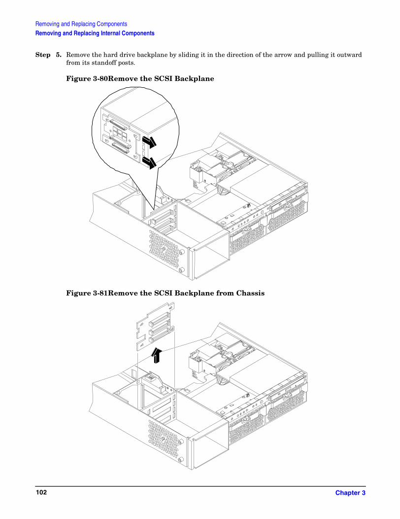
Removing and Replacing ComponentsRemoving and Replacing Internal Components
Step 5. Remove the hard drive backplane by sliding it in the direction of the arrow and pulling it outward from its standoff posts.
Figure 3-80Remove the SCSI Backplane
Figure 3-81Remove the SCSI Backplane from Chassis
Chapter 3102
Removing and Replacing ComponentsRemoving and Replacing Internal Components
Replacing the Hard Disk Drive SCSI Backplane
Step 1. Insert the hard drive backplane onto its four chassis standoffs and slide it to the left as you face it. This locks the hard drive backplane in place.
Step 2. Screw in the two backplane mounting screws and connect the two SCSI cables.
Step 3. Connect the backplane power cable and lower the fan power bridge until it snaps in place.
Step 4. Replace the PCI cage in the system and secure it.
Step 5. Replace the system cover(s), and reconnect all of the power and external cables.
Step 6. Verify the backplane replacement and operation by using the system utilities. (Refer to the Utilities chapter of the hp9000 rp3410 and rp3440 Operations Guide for additional information.)
• Use the MP commands to verify operation
• Use the BCH commands to verify operation
Chapter 3 103

Removing and Replacing ComponentsRemoving and Replacing Internal Components
Chapter 3104

A Parts Information
Field Replaceable Parts (FRU) ListThe items in this list and the corresponding item numbers are the Field Replaceable Units (FRUs) for the hp9000 rp3410 and hp9000 rp3440 Servers.
Figure A-1 Parts Identification
1
2
3
4
5
6
78
910
11
1213
14
1516
1718
19
20
21
22
23
Appendix A 105

Parts InformationField Replaceable Parts (FRU) List
Figure A-2 Tower Parts
24
25
26
27
2829
30
25
Appendix A106

Parts InformationField Replaceable Parts (FRU) List
NOTE The item numbers listed below are used with the part illustrations in order to identify the nomenclature of the part. Part numbers are found by using the part nomenclature from this list to select the correct part from the HP Partsurfer. If a system board needs to be replaced, remove processors, DIMMs, and adapter boards and transfer these to the new board. Ensure all jumper and switch settings on the old board are transferred to the new board.
Table A-1 Field Replaceable Parts (FRU) List
Item No. Description Part Number Replacement
Part Number Exchange
PCA Boards
22 Power supply interface module A7231-04018
SCSI backplane A7231-66520 A7231-69520
23 System board (mfg PN A7136-60001) A7136-67001 A7136-69001
17 PCI backplane A7231-66530
12 Display panel A7231-66550
Remote management board (ECI/Management Processor board)
A7231-66580
Optical Devices
14 DVD-ROM drive, slimline (A9919A) A7231-62012 A7231-69012
14 CD-RW/DVD-ROM combo drive, slimline (A9920A) A7231-62014 A7231-69014
Memory
2 256 DDR-SDRAM DIMM (rp3440, rp3410 (A6833-60001)) (A9908A)
A6833AX A6833-69001
2 512 DDR-SDRAM DIMM, pc2100 (rp3440, rp3410 (A6746-60001)) (A9909A0
A6746AX A6746-69001
2 1 GB DDR-SDRAM, pc2100 (rp3440 (A6834-60001)) (A9910A)
A6834AX A6834-69001
2 2 GB DDR-SDRAM, pc2100 (rp3440 (1818-8799)) (AB228A)
A6970AX A6835-69001
Internal Disks/Removable Media
15 36 GB, 15K RPM Ultra320 SCSI HotPlug disk (A9796A)
A9896-64001 A9896-69001
15 73 GB, 15K RPM Ultra320 SCSI HotPlug disk (A9977A)
A9897-64001 A9897-69001
Appendix A 107
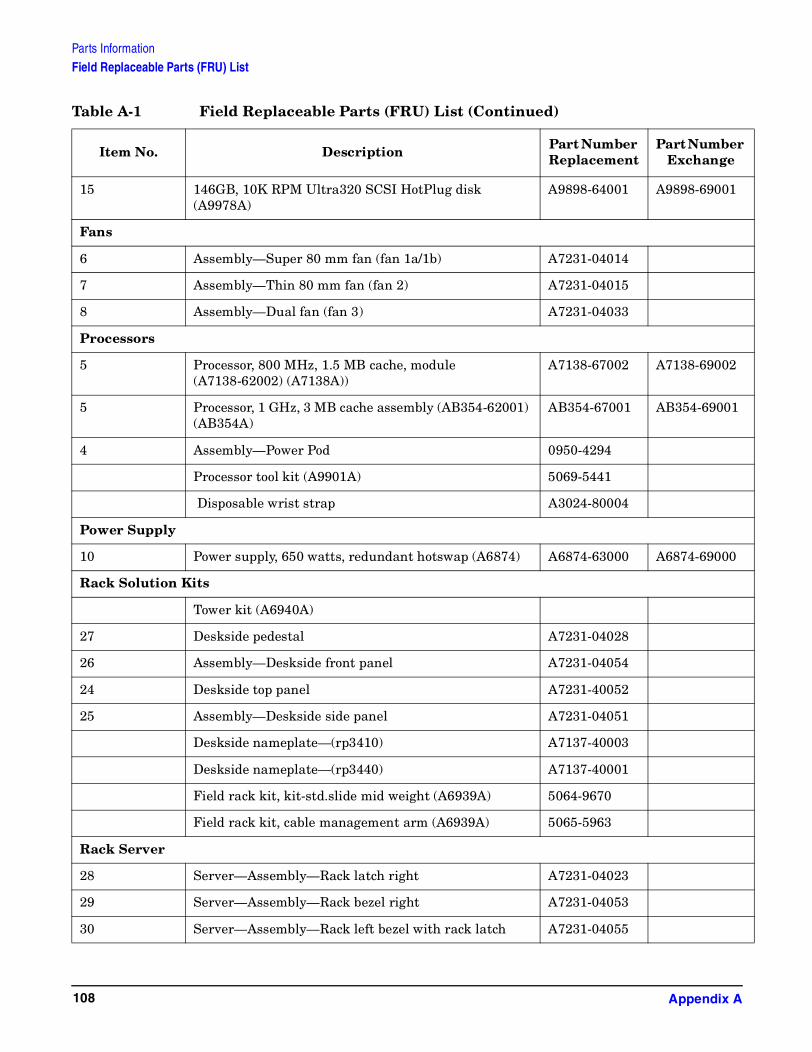
Parts InformationField Replaceable Parts (FRU) List
15 146GB, 10K RPM Ultra320 SCSI HotPlug disk (A9978A)
A9898-64001 A9898-69001
Fans
6 Assembly—Super 80 mm fan (fan 1a/1b) A7231-04014
7 Assembly—Thin 80 mm fan (fan 2) A7231-04015
8 Assembly—Dual fan (fan 3) A7231-04033
Processors
5 Processor, 800 MHz, 1.5 MB cache, module (A7138-62002) (A7138A))
A7138-67002 A7138-69002
5 Processor, 1 GHz, 3 MB cache assembly (AB354-62001) (AB354A)
AB354-67001 AB354-69001
4 Assembly—Power Pod 0950-4294
Processor tool kit (A9901A) 5069-5441
Disposable wrist strap A3024-80004
Power Supply
10 Power supply, 650 watts, redundant hotswap (A6874) A6874-63000 A6874-69000
Rack Solution Kits
Tower kit (A6940A)
27 Deskside pedestal A7231-04028
26 Assembly—Deskside front panel A7231-04054
24 Deskside top panel A7231-40052
25 Assembly—Deskside side panel A7231-04051
Deskside nameplate—(rp3410) A7137-40003
Deskside nameplate—(rp3440) A7137-40001
Field rack kit, kit-std.slide mid weight (A6939A) 5064-9670
Field rack kit, cable management arm (A6939A) 5065-5963
Rack Server
28 Server—Assembly—Rack latch right A7231-04023
29 Server—Assembly—Rack bezel right A7231-04053
30 Server—Assembly—Rack left bezel with rack latch A7231-04055
Table A-1 Field Replaceable Parts (FRU) List (Continued)
Item No. Description Part Number Replacement
Part Number Exchange
Appendix A108

Parts InformationField Replaceable Parts (FRU) List
Server rack nameplate (rp3410) A7136-40002
Server rack nameplate (rp3440) A7136-40001
Plastic and metal parts
Filler, slimline carbon A7231-40027
Filler, slimline gray A7231-40026
HDD filler—Carbon A6198-60003
HDD filler—gray A6198-60002
Assembly—Fan cage A7231-04004
16 Assembly—PCI cage A7231-04006
3 Assembly—Plastic turbocooler duct A7231-04034
ECI cover plate A7231-00072
1 Assembly—Top cover A7231-04003
Assembly—Memory air flow guide A7231-04049
Cables
IDE cable A7231-63002 None
Status panel cable A7231-63003 None
Disk power A7231-63004 None
Cable—SCSI—Channel A A7231-63017 None
Cable—SCSI—Channel B A7231-63018
Cable—Super 80 mm fan A7231-63005
Cable—80 mm fan A7231-63006
Management processor M cable A6144-63001
Flex cable for the management processor card A7231-63008
Audio cable 8121-0808
Headphone 5183-9500
PWR CORD U.S. CANADA 125 VAC 8120-1378
PWR CORD CONT. EUROPE 250 VAC 8120-1689
Chinese power cord, straight 8120-8376
PWR CORD JAPAN 125 VAC 8120-4753 None
Table A-1 Field Replaceable Parts (FRU) List (Continued)
Item No. Description Part Number Replacement
Part Number Exchange
Appendix A 109

Parts InformationField Replaceable Parts (FRU) List
PWR CORD SWITZERLAND 250 VAC 8120-2104 None
PWR CORD U.K. 250 VAC 8120-1351 None
Table A-1 Field Replaceable Parts (FRU) List (Continued)
Item No. Description Part Number Replacement
Part Number Exchange
Appendix A110
B System Information
Features SummaryThe following features comprise the hp 9000 rp 3410 and rp3440 Server.
Processor
• 800 MHz/1.5 GB cache
• 1 GHz/1.5 GB cache (hp9000 rp3440 only)
• rp3410 processors may be 1-way and 2-way
• rp3440 processors may be 1-way, 2-way, and 4-way
Memory
• 12 memory DIMM slots
• Maximum memory size of 6 GB (hp9000 rp3410) or 24 GB (hp9000 rp3440)
• 256 MB and 512 MB (hp9000 rp3410) standard 184 pins 2.5V DDR266, CL2, registered, ECC
• 256 MB, 512 MB, 1 GB and 2 GB (hp9000 rp3440) standard 184 pins 2.5V DDR266, CL2, registered, ECC
• 133 MHz memory bus frequency, 266MTransfers/s data, 8.5 GB/s peak data bandwidth
• Upgrades must be made by pairs of DIMMs minimum
• DIMMs loaded by quads enable interleaved mode and chip spare
PCI Riser
• 2 (hp9000 rp3410) or 4 (hp9000 rp3440) independent PCI-X 133 MHz 64-bit 3.3V 15W slots. No 5V card and hot-plug support
Internal Core I/O
• Dual channel SCSI U160 interface, 2 internal 68-pin connectors, 1 68-pin external connector
• The SCSI backplane is configured either as 2 channels with 2+1 drives. A SAF-TE accessory (currently not available) is required to configure the SCSI backplane as 1 channel with 3 drives
• The three internal SCSI drive connectors are of the 80-pin type and provide drive electrical hot-plug capability
• The SCSI backplane has been designed to support a SCSI management piggy board accessory that provides a SCSI management SAF-TE chip and shunts the backplane's channels A and B to provide 3 disks on channel A and leave only the external connector on channel B. This accessory is currently not available
• 1 internal IDE connector for a slim-line optical device (CD and DVD)
• No floppy connector
Appendix B 111
System InformationFeatures Summary
External Core I/O
• 1-SCSI U160 68-pin connector
• 1-10/100/1000Base-T ethernet LAN connectors for copper cable
• 4-USB 2.0 ports
• 3 DB-9 ports (Console, UPS, and Modem) via 3-connector M cable
Power Supply Unit
• 650W output power
• The power supply is split in a front end block (the actual power supply case) that converts the line voltage into a high DC voltage and back end voltage regulation modules (on the motherboard) that step down the front end DC voltage to the required voltages
• Redundant and hot-plug power supplies (front end block only)
Motherboard Manageability
• Baseboard Management Controller (BMC)
• Temperature monitoring and fans regulation by BMC
• BMC manageability console shared with system console/general purpose serial port
• IPMI protocol for communication between BMC/system/MP card
• Hardware diagnostics by BMC displayed on the front status panel
• Locator front/rear LEDs
• Field replacement units monitoring by BMC
Enhanced Server Manageability Using Management Processor
• LAN telnet console
• Web console
• Serial port for local console
• Serial port for modem console
• Duplication of console screen content across all consoles
Hard Disk Drives
• Three, 1/2 inch hard disk drives (1 inch height)—rp3413
Appendix B112

System InformationSystem Board
System BoardThis section provides a block diagram of the system board and descriptions of key components (integrated circuits) on the board.
Figure B-1 System Block Diagram
System Board Components
The following describes the main components of the system board:
• PA-RISC processor (one or two processors supported)
• ZX1 I/O and memory controller
• ZX1 PCI bus controller
• Processor dependent hardware controller
• Field processor gate array controller
ASICBus
Interface
ASICBus
Interface
ASICBus
Interface
ASICBus
Interface
ASICBus
Interface
ASICBus
Interface ASICBus
Interface
ASICBus
Interface
ASICBus
Interface
PA-RISCProcessor
PA-RISCProcessor
*
*
*Factory use only
Appendix B 113

System InformationSystem Board
• Baseboard management controller
• SCSI controller
• IDE controller
• USB controller
• 10/100/1000 LAN
PA RISC Processor
The system board consists of two Zero Insertion Force (ZIF) processor sockets, the Core Electronic Complex (CEC), and circuitry for clock and power generation and distribution, boundary Scan, In-target Probe (ITP), and debug.
The Front Side Bus (FSB) is the IA64 processor bus based on bus protocol from Intel. Unlike previous PA-RISC microprocessors that utilized HP's proprietary processor bus, this processor is designed to utilize the FSB. This allows processor FRUs (Field Replaceable Units) to be dropped in, provided that electrical/ mechanical compatibility and support circuitry exist. For the purposes of this document, a FRU consists of a single processor module, a y power pod, and the y heatsink assembly.
One end of the FSB is terminated with an I/O ASIC. The other end of the bus is terminated with a FRU. In the middle, an additional FRU can be loaded. For the system to function properly, the processor farthest away from the I/O ASIC must be loaded at all times to electrically terminate the FSB.
Each processor module plugs directly into and is powered by its own 12V to 1.2V power-pod. Other power for the system board comes from multiple on-board DC/DC converters. Each processor module is attached to the board through a ZIF socket and the entire FRU secured down by a heatsink bolster plate.
Processor Bus
The processor bus (Front Side Bus [FSB]) in this product runs at 200 MHz. Data on the FSB are transferred at a double data rate, which allows a peak FSB bandwidth of 6.4 GB/sec.
ZX1 I/O and Memory Controller
The rp3410 and rp3440 Servers support the following features of the ZX1 I/O and memory controller chip:
• 3.3 GB/s peak IO bandwidth
• Provides 7 communication paths
• Peak memory bandwidth of 8.5 GBs
• 2 memory cells, 144 data bits each
Memory
The memory subsystem provides two memory cells, each of which is 144 data bits wide. Each cell has 6 DIMM slots, which means a total of 12 DIMM slots are available. The memory bus clock speed is 133 MHz, and the data transfer rate is 266Mtransfers/second as data is clocked on both edges of the clock. The peak data bandwidth for this memory subsystem design is 8.5 GB/s. DIMMs must be loaded in quads with qualified modules, with the exception of 256 MB DIMMs which can be loaded in pairs. Memory is protected by data ECC, and the hardware implementation supports the chip-spare (similar to IBM's capital) feature.
Appendix B114

System InformationSystem Board
The minimum amount of memory that can be installed is 512 MB (2-256 MB modules). The maximum amount of memory that can be installed is dependent on the largest DIMM size (2 GB). When the product is initially released, 24 GB will be that maximum memory size.
This design does not support any non industry standard DDR DIMMs. Only qualified DIMMs are supported.
Figure B-2 Memory Block Diagram
Memory Architecture
The I/O ASIC memory interface supports two DDR cells, each of which is 144 data bits wide. The memory subsystem physical design uses a comb-filter termination scheme for both the data and address/control buses. This part of the topology is similar to other DDR designs in the computer industry. Clocks are distributed directly from the I/O ASIC; each clock pair drives 2 DIMMs.
Memory data is protected by ECC (Error Correction Code). 8 ECC bits per DIMM protect 64 bits of data. The use of ECC allows correction of single-bit errors, and detection of multi-bit errors. Only DIMMs with ECC will be qualified or supported.
DIMMs
The memory subsystem will only support DDR SDRAM (Double Data Rate Synchronous Dynamic Random Access Memory) technology utilizing industry-standard PC-1600 type DDR SDRAM DIMMs, 1.2" tall. This is expected to be the standard height available at first release and is currently being used by high-volume products. The DIMMs use a 184-pin JEDEC standard connector.
MemoryController
Appendix B 115

System InformationSystem Board
DIMMs are loaded in groups of four, known as a rank (except for 256 MB DIMMs, which can be loaded in pairs). All four DIMMs in a rank must be the same size. The following table summarizes the memory solutions.
Memory Array Capacities
Min / Max Memory Size Single DIMM Size DDR SDRAM Count, Type and Technology
• 0.5 GB / 3 GB 256 MB DIMM 18 x 32 MB x 4 DDR SDRAMs (128 MB)
• 2 GB / 6 GB 512 MB DIMM 36 x 32 MB x 4 DDR SDRAMs (128 MB)
• 4 GB / 12 GB 1024 MB DIMM 36 x 64 MB x 4 DDR SDRAMs (256 MB)
• 8 GB / 24 GB 2048 MB DIMM 36 x 128 MB x 4 DDR SDRAMs (512 MB)
Chip Spare Functionality
Chip spare enables an entire DDR SDRAM chip on a DIMM to be bypassed in the event that a multi-bit error is detected on the DDR SDRAM. In order to use the chip spare functionality on your system, only DIMMs built with ×4 DDR SDRAM parts can be used, and these DIMMs must be loaded in quads.
The memory subsystem design supports the I/O ASIC chip’s spare functionality. Chip spare enables an entire SDRAM chip on a DIMM to be bypassed/replaced in the event that a multi-bit error is detected on that SDRAM. In order to use the chip spare functionality on, only DIMMs built with x4 SDRAM parts can be used, and these DIMMs must be loaded in quads (2 DIMMs per memory cell, loaded in the same location in each memory cell). Each DIMM within a quad must be identical to all the other DIMMs in the quad.
Using the DIMM loading order figure from above, chip spare can be achieved if 4 identical DIMMs are loaded in the slots labeled “1st” and “2nd.” If more DIMMs are added, they must be loaded in quads in order to maintain the chip spare functionality. So, if more DIMMs are added in to the example case, 4 identical DIMMs (identical to each other, but can be different from the original quad that was loaded) must be loaded in the slots labeled “3rd” and “4th.”
Serial Presence Detect
Each DIMM contains an I2C EEPROM whose content describes the module's characteristics: speed, techno, revision, vendor, etc. This feature is called serial presence detect (SPD). Firmware typically uses this information to detect unmatched pairs of DIMMs, and configure certain memory subsystem parameters. The SPD information for DIMMs loaded in the system will also be accessible to the baseboard management controller (BMC) through the I2C bus.
I/O Bus Interface
The I/O bus interface has these features:
• Provides industry standard PCI 33 MHz and 66 MHz, PCI-X 66 MHz to 133 MHz, 32 or 64 data bit support
• Uses 3.3V PCI only, and it does not support 5V PCI
• Optimizes for DMA performance
• Supports 3.3V or universal-keyed PCI cards. 5V-keyed PCI cards are not supported
Appendix B116

System InformationSystem Board
Processor Dependent Hardware (PDH) Controller
The Processor Dependent Hardware (PDH) controller provides these features:
• 16-bit PDH bus with reserved address space for
— Flash memory
— Nonvolatile memory
— Scratch RAM
— Real time clock
— UARTs
— External registers
— Firmware read/writable registers
— Two general purpose 32-bit registers
— Semaphore registers
— Monarch selection registers
— Test and reset register
• Reset and INIT generation
Field Programmable Gate Array (FGPA)
The Field Programmable Gate array (FPGA) provides ACPI and LPC support for the PDH bus and provides these features:
• ACPI 2.0 interface
• LPC bus interface to support BMC
• Decoding logic for PDH devices
Baseboard Management Controller (BMC)
The baseboard management controller supports the industry-standard Intelligent Platform Management Interface (IPMI) specification. This specification describes the management features that have been built into the system board. These features include: diagnostics (both local and remote) console support, configuration management, hardware management and troubleshooting.
The baseboard management controller provides the following:
• Compliance with Intelligent Platform Management Interface 1.0
• Tachometer inputs for fan speed monitoring
• Pulse width modulator outputs for fan speed control
• Push-button inputs for front panel buttons and switches
• One serial port, multiplexed with the system console port
• Remote access and intelligent chassis management bus (IC MB) support
• Three I2C master/slave ports (one of the ports is used for IPMB
Appendix B 117

System InformationSystem Board
• Low Pin Count (LPC) bus provides access to three Keyboard Controller Style (KCS) and one-Block Transfer (BT) interface
• 32-bit ARM7 RISC processor
• 160-pin Low Profile Flat Pack (LQFP) package
• Firmware is provided for the following interfaces:
— Intelligent Platform Management Interface (IPMI)
— Intelligent Platform Management Bus (IPMB)
SCSI Controller
The SCSI controller is a LSI Logic 53C1030 chip. This chip is fully compliant with the SCSI Peripheral Interface-4 Specification (SPI-4). It has two independent SCSI channels supporting devices at speeds up to 320 MB/sec each. The 53C1030 adheres to the PCI-X addendum, to the PCI Local Specification, and is hard-wired to PCI ID 1 which corresponds to bit 17 of the PCI AD bus.
IDE Interface
The IDE controller (PCI649) supports the ATAPI zero (0) to five (5) modes (from 16 to 100 MB/s). The usable speed on this system is limited to 16 MHz (ATA-33 mode, 33 MB/s) because the slimline CD/DVD devices do not support the ATA-66 and 100 modes.
The primary IDE channel is the only channel that is implemented. The IDE cable provides only one drive connector, of the master type, for the optical storage peripheral.
1GB System LAN
The 1GB System LAN port provides:
• Main system LAN
• 10/100/1000 MB capable
USB Connectors
The USB connectors provide:
• High speed 480 MB/sec. capable
• Full speed 12 MB/sec. and low speed 1.5 Mb/sec
• Support for USB keyboard and mouse
• HP-UX supports HP USB keyboard and mouse
Appendix B118

Index
AAccessing a Rack Mounted HP Server, 39Airflow Guides, Replacing, 55
BBackplane, PCI
Remove, 81Replace, 82
Backplane, SCSIRemove, 99Replace, 103
Baseboard Management Controller (BMC), 117Battery, MP Card
Remove, 86Replace, 87
Battery, SystemRemove, 76Replace, 76
Bezel ReplacementRack Configuration, 34, 39
BMC, 117
CCleaning, 30Commands, OCE, 17Control Panel, Front, LEDs, 19Controller
Baseboard Management, 117Processor Dependent Hardware, 117SCSI, 118
Conventions, Typographical, 9Core I/O
External, 112Internal, 111
Cover, MetalRemove, 40Replace, 41
Cover, SideRemove, 34Replace, 36
Covers, Replacing, 34
DDiagnostic LEDs, 20DIMM, Memory
Installing, 61Supported, 59
Disk Drive BackplaneFeatures, 112Replace, 103
Disk Drive, Hot-PlugRemove, 50Replace, 52
DVD DriveRemove, 83Replace, 83
EEvent Monitoring Service (EMS), 13
External Core, Features I/O, 112
FFan, Hot-Swap
Remove, 45Replace, 47
FeaturesExternal Core I/O, 112Internal Core I/O, 111Memory, 111Motherboard Manageability, 112PCI Riser, 111Power Supply Unit, 112Processor, 111
Field Programmable Gate Array, 117Field Replace Unit (FRU) List, 105Front Bezel
Rack Configuration, 39Tower Configuration, 34
FRU List, 105
GGate Array, Field Programmable, 117Graphics Cards, Replacing, 77
HHard Disk
Replace, 103Hard Drive
Features, 112Remove, 99
Hot Swap Fan, 45Hot-Plug Disk Drive, 49Hot-Swap Power Supply, 47
II/O and Memory Controller, 114I/O Bus Interface, 116I/O, External Core, 112I/O, Internal Core, 111IDE Interface, 118Internal Core I/O, Features, 111
LLAN, 27LED Status Panel, Replacing, 88LEDs
Control Panel, 19Diagnostic, 20MP, LEDs, 27Status Panel, Replacing, 88System Board, 28Troubleshooting, 19
MManagement Processor
Remove, 84Replace, 86Using, 14
119

Index
Management Processor Card BatteryRemove, 86Replace, 87
MemoryDescription, 114Features, 111
Memory, DIMMDescription, 59, 111, 115Installing, 61Removing, 60Supported, 59
Methodology, Troubleshooting, 11
OODE Commands, 17Offline Diagnostic Environment (ODE), 17
PParts List (FRU), 105PCI and Graphics Card, Replacing, 77PCI Backplane
Remove, 81Replace, 82
PCI RiserFeatures, 111
Power Button, 12Power Supply Interface Module
Remove, 96Replace, 98
Power Supply, Hot-SwapFeatures, 112Remove, 47Replace, 49
Processor Airflow GuideRemove, 57Replace, 59
Processor Dependent Hardware Controller, 117Processor Module
Description, 111Features, 111PA RISC, 114Remove, 63Replace, 70Troubleshooting, 23
RRelated Documents, 10Remove and Replace
Accessing a Rack Mounted HP Server, 39Battery, Management Processor Card, 86Covers, 34DIMMs, 59Disk Drive Backplane, 99Disk Drive, Hot-Plug, 49Extend HP Server form Rack, 39Fan, Hot-Swap, 45Front Bezel, 38Graphics Cards, 77LED Status Panel, 88
Management Processor Card, 84Management Processor Card Battery, 86Memory, 59PCI Backplane, 81PCI Cards, 77Power Supply Interface Module, 96Power Supply, Hot-Swap, 47Processor Module, 62Removable Media (CD-DVD), 82SCSI Backplane, 99Service Tools Required, 31System Battery, 76System Board, 89
SSafety Information, 31SCSI Backplane
Remove, 99Replace, 103
SCSI Controller, 118Support Tools Manager (STM), 13System Battery, Replacing, 76System Board, 28System Board, LEDs, 89System Event Log, 14System Features, 111
TTools Required for Removal and Replacement, 31Troubleshooting
Event Monitoring Service (EMS), 13Identifying and Diagnosing Problems, 19Management Processor, 14Methodology, 11Offline Diagnostic Environment (ODE), 17Support Tools Manager (STM), 13System Event Logs (SEL), 14Using LEDs, 19
Typographical Conventions, 9
120