RP32 3InServiceInspection Manag.
55
RP 32-3 INSPECTION AND TESTING OF IN-SERVICE CIVIL AND MECHANICAL PLANT-MANAGEMENT PRINCIPLES October 1998 Copyright © The British Petroleum Company p.l.c.
-
Upload
mohd-khairul -
Category
Documents
-
view
46 -
download
6
description
RP32 3InServiceInspection Manag.
Transcript of RP32 3InServiceInspection Manag.

RP 32-3
INSPECTION AND TESTING OFIN-SERVICE CIVIL AND MECHANICAL
PLANT-MANAGEMENT PRINCIPLES
October 1998
Copyright © The British Petroleum Company p.l.c.

Copyright © The British Petroleum Company p.l.c.All rights reserved. The information contained in this document is subject to the termsand conditions of the agreement or contract under which the document was supplied tothe recipient's organisation. None of the information contained in this document shall bedisclosed outside the recipient's own organisation without the prior written permission ofManager, Standards, BP International Limited, unless the terms of such agreement orcontract expressly allow.
BP GROUP RECOMMENDED PRACTICES AND SPECIFICATIONS FOR ENGINEERING
Issue Date October 1998
Doc. No. RP 32-3 Latest Amendment Date
Document Title
INSPECTION AND TESTING OFIN-SERVICE CIVIL AND MECHANICAL
PLANT-MANAGEMENT PRINCIPLES
APPLICABILITY
Regional Applicability: International
SCOPE AND PURPOSE
This Recommended Practice gives guidance on the organising and management ofInspection and Testing of In-Service Civil and Mechanical Plant and is for use onshoreand offshore.
Its purpose is to define organisational responsibilities and procedures based oneconomical safe practice.
AMENDMENTSAmd Date Page(s) Description___________________________________________________________________
CUSTODIAN (See Quarterly Status List for Contact)
InspectionIssued by:-Engineering Practices Group, BP International Limited, Research & Engineering CentreChertsey Road, Sunbury-on-Thames, Middlesex, TW16 7LN, UNITED KINGDOMTel: +44 1932 76 4067 Fax: +44 1932 76 4077 Telex: 296041

RP 32-3INSPECTION AND TESTING OF IN-SERVICE CIVIL AND
MECHANICAL PLANT-MANAGEMENT PRINCIPLES
PAGE i
CONTENTSSection Page
FOREWORD ..........................................................................................................................iii
1. SCOPE .................................................................................................................................1
2. ORGANISATION ...............................................................................................................1
2.1 Management Responsibility ..........................................................................................12.2 Management Delegation................................................................................................22.3 Organisational Structure ................................................................................................22.4 Inspection Function Responsibilities.............................................................................22.5 Inspection Staff..............................................................................................................32.6 Specialist Services .........................................................................................................32.7 External Inspection Bodies............................................................................................4
3. STAGES OF INSPECTION...............................................................................................5
3.1 Design .....................................................................................................................53.2 Manufacture...................................................................................................................53.3 Construction ..................................................................................................................63.4 Commissioning..............................................................................................................63.5 Operational ....................................................................................................................6
4. CLASSIFICATION AND REGISTRATION...................................................................7
4.1 Identification..................................................................................................................74.2 Classification .................................................................................................................74.3 Registration....................................................................................................................74.4 Change of Conditions of Use.........................................................................................84.5 Plant Modification and Repairs .....................................................................................8
5. FREQUENCY AND EXTENT OF INSPECTION ..........................................................8
5.1 General .....................................................................................................................85.2 Class B Equipment ........................................................................................................8
5.2.1 Introduction...............................................................................................85.2.2 Allocation of Grades .................................................................................95.2.3 Inspection Grades......................................................................................95.2.3.1 Inspection Grade 0 .................................................................................95.2.3.2 Inspection Grade 1 ...............................................................................105.2.3.3 Inspection Grade 2 ...............................................................................105.2.3.4 Inspection Grade 3 ...............................................................................105.2.4 Criticality Rating Systems.......................................................................115.2.5 Determination of Inspection Frequency..................................................115.2.6 Extensions...............................................................................................11
5.3 Class C Equipment ......................................................................................................125.4 Types of Inspection......................................................................................................12
5.4.1 Initial Thorough Inspection.....................................................................12

RP 32-3INSPECTION AND TESTING OF IN-SERVICE CIVIL AND
MECHANICAL PLANT-MANAGEMENT PRINCIPLES
PAGE ii
5.4.2 Subsequent Thorough Inspections ..........................................................135.4.3 Sample Inspection...................................................................................135.4.4 Inspection Reviews .................................................................................14
5.5 Inspection Grade Transfers..........................................................................................155.5.1 Principles.................................................................................................155.5.2 Grade Transfers - Thorough Inspection ..................................................155.5.3 Grade Transfers - Sample Inspections ....................................................15
5.6 Special Cases ...............................................................................................................165.6.1 Exemptions .............................................................................................165.6.2 Replacement Equipment .........................................................................165.6.3 Special Design and Construction ............................................................165.6.4 Mature Design.........................................................................................175.6.5 Deferred Start-up and Intermittent Operation .........................................17
6. INSPECTION REPORTS AND RECORDS ..................................................................18
6.1 Records ...................................................................................................................186.2 Statutory Documents ...................................................................................................196.3 Reports ...................................................................................................................19
7. REVIEW OF INSPECTION FUNCTION......................................................................20
7.1 Introduction .................................................................................................................207.2 Internal Review - Self Regulation ...............................................................................207.3 External Review ..........................................................................................................20
TABLE 1 - EQUIPMENT - RECOMMENDED INSPECTION INTERVALS..............21
APPENDIX A.........................................................................................................................22
DEFINITIONS AND ABBREVIATIONS........................................................................22
APPENDIX B.........................................................................................................................24
LIST OF REFERENCED DOCUMENTS ........................................................................24
APPENDIX C.........................................................................................................................25
ENDORSEMENT REVIEW PROCEDURE ....................................................................25C.1 Introduction.................................................................................................................25C.2 Methodology ...............................................................................................................26C.3 Set up Study ................................................................................................................27C.4 Preparation for Study ..................................................................................................29C.5 Study ...................................................................................................................32C.6 Action and Follow Up.................................................................................................35C.7 Plant Item Information Form ......................................................................................36C.8 Response Form............................................................................................................40C.9 Fluid Definition Form.................................................................................................41C.10 Guide phrases/words in matrix format......................................................................43C.11 Blank examples of PIIF, FDF and RF forms ............................................................45C.12 Example Review.......................................................................................................51

RP 32-3INSPECTION AND TESTING OF IN-SERVICE CIVIL AND
MECHANICAL PLANT-MANAGEMENT PRINCIPLES
PAGE iii
FOREWORD
Introduction to BP Group Recommended Practices and Specifications for Engineering
The Introductory Volume contains a series of documents that provide an introduction to theBP Group Recommended Practices and Specifications for Engineering (RPSEs). Inparticular, the 'General Foreword' sets out the philosophy of the RPSEs. Other documents inthe Introductory Volume provide general guidance on using the RPSEs and backgroundinformation to Engineering Standards in BP. There are also recommendations for specificdefinitions and requirements.
Value of this Recommended Practice
This document represents the accumulated management principles that relate to theInspection and Testing of In-Service Civil and Mechanical Plant, for ensuring a high standardof plant integrity based on economical safe practice.
Application
Text in italics is Commentary. Commentary provides background information whichsupports the requirements of the Recommended Practice, and may discuss alternative options.
This document may refer to certain local, national or international regulations but theresponsibility to ensure compliance with legislation and any other statutory requirements lieswith the user. The user should adapt or supplement this document to ensure compliance forthe specific application.
Principal Changes from Previous Edition
Appendix C has been added
Feedback and Further Information
Users are invited to feed back any comments and to detail experiences in the application ofBP RPSE's, to assist in the process of their continuous improvement.
For feedback and further information, please contact Standards Group, BP International orthe Custodian. See Quarterly Status List for contacts.

RP 32-3INSPECTION AND TESTING OF IN-SERVICE CIVIL AND
MECHANICAL PLANT-MANAGEMENT PRINCIPLES
PAGE 1
1. SCOPE
This Recommended Practice gives guidance on the organisation and management ofinspection and testing of in-service civil and mechanical plant. It is applicable to oilrefineries, petrochemical and chemical plant, onshore and offshore productionfacilities, transmission pipelines and storage and distribution facilities for finishedproducts. It is not applicable to road, rail or sea transportation.
It defines organisational responsibilities, procedures for registration, classification,frequency of inspection, reporting and recording for civil and mechanical plant basedon economical safe practice and experience in the oil and chemical industries.
2. ORGANISATION
2.1 Management Responsibility
The inspection of equipment, must be given adequate considerationthrough all stages from initial design through shop manufacture, sitefabrication or erection, commissioning and subsequent operation untilpermanent de-commissioning and disposal. This RecommendedPractice assumes that equipment has been designed, fabricated andinstalled according to codes, standards or specifications approved byBP. It should also be used for guidance for those installations whereBP has not been involved in design, fabrication and installation.Where BP has not been involved then management should ensure thatdesign, construction, installation and testing has been carried out torecognised industry standards and codes.
It is the responsibility of management at each operating centre to:-
(a) Ensure that installed equipment is suitable for its currentservice and that it is in a safe condition to commission andoperate and that documentation to this effect is available.
(b) Ensure compliance with national statutory regulationsapplicable to design, operation, inspection, test andcertification of equipment.
(c) Ensure that the inspection requirements as defined by thisRecommended Practice are implemented, so that equipment ismaintained suitable for operation consistent with the primerequirements of safety, compliance with national statutoryregulations and economical operation, in that order of priority.

RP 32-3INSPECTION AND TESTING OF IN-SERVICE CIVIL AND
MECHANICAL PLANT-MANAGEMENT PRINCIPLES
PAGE 2
2.2 Management Delegation
The management of each centre should delegate the responsibility -and the authority - for the correct application of this RecommendedPractice to those persons or departments most appropriate and with thenecessary technical abilities and qualifications. This delegation ofresponsibility and authority should be in writing.
2.3 Organisational Structure
The management is responsible for ensuring that the inspectionfunction is given terms of reference in writing defining the activitiesfor which it is responsible. These terms of reference should ensurethat the inspection function is able to offer advice unbiased bypressures from other operational or engineering functions.
The inspection function should have direct access to the operatingcentre senior management for those occasions:-
(a) when it is not possible to reach an agreement acceptable to allfunctional groups,
(b) when the inspection function considers it necessary to advisethe management of critical information affecting the health andsafety of personnel or equipment.
2.4 Inspection Function Responsibilities
The basic responsibilities of an inspection function should be:-
(a) To carry out inspection of all equipment in accordance with therequirements of this Recommended Practice, in so far as it isadopted by the operating centre management.
(b) To classify equipment and allocate appropriate InspectionGrades to that equipment.
(c) To maintain a register of all equipment, together with detailedand comprehensive records of each item.
(d) To ensure that adequate notice is given when items ofequipment are due for inspection.
(e) To inform the management of any items of equipment whichbecome overdue for their next inspection and advise on thecorrective action to be taken.

RP 32-3INSPECTION AND TESTING OF IN-SERVICE CIVIL AND
MECHANICAL PLANT-MANAGEMENT PRINCIPLES
PAGE 3
(f) To advise the management whenever the inspection intervals ofany item of equipment are reduced or if abnormal conditions ofcorrosion, erosion or other form of deterioration are detected.
(g) To advise on limiting conditions of pressure or temperature orother conditions of service to which items of equipment may besubjected.
(h) To verify that repairs, modification or renewals to equipmentare carried out to the specified design.
(i) To have trained, competent and qualified staff to assist incarrying out the duties which are ascribed to it or to securespecialist advice and assistance as necessary to enable it todischarge its responsibilities in a satisfactory manner.
2.5 Inspection Staff
Inspection Engineers, should be properly trained and qualified andrecognised as competent persons for the work which they carry out.
The Inspection Body employing such engineers, either an in-house BPGroup or a third party Independent Inspection Authority, shoulddemonstrate competence as a body by compliance with the principlesof EN 45004: 1995 (or the ISO equivalent); General criteria for theoperation of various types of bodies performing inspection.
In the UK this should be demonstrated by the Inspection Body beingaccredited to BS EN45004: 1995 by UKAS (United KingdomAccreditation Service). For those bodies not presently accredited,progression towards accreditation in a timely manner should bedemonstrated.
In the EEC the accreditation will be by the appropriate national bodywhich provides accreditation of inspection bodies and should becompleted as soon as reasonably possible following the appointment ofthe accreditation body.
In areas outside of the EEC the principles laid down in EN 45004should be adopted by operating units when developing In-houseInspection Bodies or selecting external bodies. Cross business peerreview and assistance from SPR or OTN may be used to confirmcompliance.
2.6 Specialist Services
From time to time it is necessary to supplement the inspection functionwith additional personnel to provide either:-
(a) specialist technical services,
(b) additional personnel to cope with periods of peak activity.

RP 32-3INSPECTION AND TESTING OF IN-SERVICE CIVIL AND
MECHANICAL PLANT-MANAGEMENT PRINCIPLES
PAGE 4
These additional personnel may be from specialist, competentcompanies or BP personnel from other centres.
Personnel from outside the operating centre should be directlyresponsible to a member of the inspection function who will directtheir activities, and be responsible for accepting their reports.
All specialist personnel should have recognised qualifications andexperience appropriate to their field of expertise.
2.7 External Inspection Bodies
In some of the countries in which BP operates, regulations require thatexaminations are carried out by an external inspection body. Evenwhere there is no statutory requirement, BP may elect to use anexternal inspection body for such work.
The Inspection Body, should demonstrate competence as a body bycompliance with the principles of EN 45004: 1995 (or the ISOequivalent); General criteria for the operation of various types ofbodies performing inspection.
In the UK this should be demonstrated by the Inspection Body beingaccredited to BS EN45004: 1995 by UKAS (United KingdomAccreditation Service). For those bodies not presently accredited,progression towards accreditation in a timely manner should bedemonstrated.
In the EEC the accreditation will be by the appropriate national bodywhich provides accreditation of inspection bodies and should becompleted as soon as reasonably possible following the appointment ofthe accreditation body.
In areas outside of the EEC the principles laid down in EN 45004should be adopted by operating units when developing In-houseInspection Bodies or selecting external bodies. Cross business peerreview and assistance from SPR or OTN may be used to confirmcompliance.
Where an external inspection body is used, the inspection function willnormally be responsible for ensuring:-
(a) That management is advised of all requirements for statutoryinspection as appropriate

RP 32-3INSPECTION AND TESTING OF IN-SERVICE CIVIL AND
MECHANICAL PLANT-MANAGEMENT PRINCIPLES
PAGE 5
(b) That all information relative to the examination is madeavailable to BP.
(c) That recommendations for repairs, renewals, etc., areadequately discussed and agreed by BP.
In general, the statutory regulations express only the minimumnecessary to satisfy legal requirements, and the documentationsupplied by an external inspection body following their examination ofan item is essentially a certificate that the item examined meets therequirements of the legislation.
Sometimes this is insufficient for BP purposes. At the discretion ofthe inspection function, a BP inspection engineer may supplement thework done by the surveyor acting for the external inspection body inorder to obtain more detailed information on the condition of the itemin question and to predict future repairs and safe life.
3. STAGES OF INSPECTION
3.1 Design
Inspection requirements for manufacture, fabrication, construction,commissioning and future operations should be considered at thedesign stage.
Each significant item of equipment should at this stage be assigned acriticality rating to cover the non-operational stages, based on therecommendations of BP Group RP 50-1 or other accepted criticalityrating system. This rating is used, together with other local factors,when deciding the level of inspection to apply during manufacture,fabrication and construction.
In many countries, there are statutory requirements covering the designof pressure vessels, containers, lifting appliances and certain otherclasses of equipment. Approval of these designs may be bygovernment-approved inspection agencies only.
3.2 Manufacture
General inspection and test procedures for new equipment duringmanufacture are covered in BP Group RP 32-1.
3.3 Construction
Guidance for site inspection and testing of new plant duringconstruction is in BP Group RP 32-2.

RP 32-3INSPECTION AND TESTING OF IN-SERVICE CIVIL AND
MECHANICAL PLANT-MANAGEMENT PRINCIPLES
PAGE 6
Site fabrication usually involves installation of equipment under moreonerous and demanding conditions than works manufacture.Appropriate inspection controls are needed to ensure fabricationstandards are met. Project teams should co-operate fully with siteinspection functions to ensure acceptable standards are being followedand that adequate data and information is being collated for futureoperational purposes. Deviations from design or specification and anyconcessions to incorporate such deviations should be fully documentedfor future reference.
3.4 Commissioning
Guidance for inspection and test of new equipment prior tocommissioning is covered in BP Group RP 32-2.
Pre-commissioning and commissioning procedures should be agreedbetween BP and the contractor. In the case of projects directed by anoperating centre these should be prepared by the operationalmanagement. These procedures should cover all requirements andlimitations in operating conditions as required by the design. Theoperation of protective interface and safety devices should be givenspecial attention.
3.5 Operational
The degree and frequency of inspection and maintenance of equipmentafter commissioning depends on many factors, but the primeconsiderations are health, safety and current criticality.
Management also require up-to-date information on plant condition, itsrate of deterioration, future repairs or replacements and predicted safeoperating life.
Periodic inspection must be tailored to suit each item and its particularneeds and will include:-
(a) Regular planned inspection to ensure safe, reliable and efficientoperation.
(b) Periodic review of operating conditions and external influencesto assess their possible effect on previous inspection reportconclusions and inspection intervals. Such reviews mayinvolve limited inspection to verify assumptions.

RP 32-3INSPECTION AND TESTING OF IN-SERVICE CIVIL AND
MECHANICAL PLANT-MANAGEMENT PRINCIPLES
PAGE 7
4. CLASSIFICATION AND REGISTRATION
4.1 Identification
All equipment requiring periodic inspection should be identified by aunique identification number. With the exception of piping systemsthis should be stamped or otherwise clearly marked on the equipment.A plant register should be maintained and there should be a procedurefor updating this register.
4.2 Classification
Equipment should be classified as either A (Statutory), B (Non-Statutory) or C (Low Risk).
Class A includes all items which are subject to fixed period inspectionin accordance with national or local regulations. The external orstatutory classification will vary from one country to another.
Class B includes items not included in the statutory classification, butsubject to periodic inspection and review.
Class C includes all items not classified as A or B and which aresubject to unscheduled inspection and review. Class C coversequipment on low hazard duty whose criticality in terms of safetyconsequences and operational reliability does not justify a periodicinspection strategy.
This equipment should normally be controlled within a routine maintenanceprogramme.
4.3 Registration
In addition to the identification of items of equipment individualrecords shall be maintained for each item. (See Section 6). When anitem is registered a file will be opened for that item and shall containall relevant design and inspection data. This data may be storedelectronically.
Although paper systems can be used for recording purposes, this should be carriedout using a computerised maintenance management system.
4.4 Change of Conditions of Use
Where it is proposed to transfer equipment to a different duty theclassification of the equipment and the inspection grading must be thesubject of review. Where a change of operating conditions isproposed, including changes in design throughput, carefulconsideration must be given to the possible effects on the equipment

RP 32-3INSPECTION AND TESTING OF IN-SERVICE CIVIL AND
MECHANICAL PLANT-MANAGEMENT PRINCIPLES
PAGE 8
and the inspection grading confirmed or modified. Adequateconsideration should also be given to the effects of the change of dutyto associated plant and systems, particularly safety and pressure reliefsystems.
4.5 Plant Modification and Repairs
Any proposed modification or repairs to plant or equipment must besubject to a formal system of approval in which the design, fabrication,inspection and test requirements are considered by appropriatespecialists. The operating centre, in conjunction with inspectionfunction, should ensure that the modifications and repairs are carriedout in accordance with detailed work instructions and procedures, thatfull documentation of all technical details is retained in the recordssystems and that, if appropriate, changes are made to the classificationand/or inspection grading of the item.
See commentary for 4.3.
5. FREQUENCY AND EXTENT OF INSPECTION
5.1 General
The intervals which may elapse between inspections for Class Aequipment shall be in accordance with the relevant statutoryregulations. Where such regulations permit flexibility and selfregulation in setting intervals the philosophy and intervalsrecommended for Class B equipment in this Recommended Practiceshould be followed.
5.2 Class B Equipment
5.2.1 Introduction
All non-statutory equipment used in operating centres falls withinClass B or Class C.
The choice of inspection frequency can be made only by persons whoare thoroughly familiar with the equipment and its operatingconditions.
This RP includes four concepts which are inter-related and from whichdecisions may be made regarding inspection frequency:-
(a) The allocation of Inspection Grades.
(b) Inspection review procedures.

RP 32-3INSPECTION AND TESTING OF IN-SERVICE CIVIL AND
MECHANICAL PLANT-MANAGEMENT PRINCIPLES
PAGE 9
(c) Sample inspection procedures.
(d) The exemption of equipment from the requirements of thisRecommended Practice.
The maximum intervals for the particular Inspection Grade must not beexceeded unless there are sound technical reasons for doing so, notingthe special case considerations in 5.6. Such reasons must be clearlyrecorded in the equipment record file.
5.2.2 Allocation of Grades
Equipment in Class B should be subject to scheduled periodicinspection and should be allocated an Inspection Grade 0, 1, 2 or 3which indicates the maximum interval that may elapse betweenthorough inspections. (See Section 5.2.5 and Table 1).
Some of the factors to be considered when assessing the InspectionGrade to be allocated are:-
(a) Severity of service duty and the risk (probability xconsequences) of failure of the item.
(b) Previous history of similar equipment on similar duties.
(c) The original standards of design, materials and construction.
(d) The age of the item and the length of time it has been incommission.
(e) The proper use of components and materials.
5.2.3 Inspection Grades
5.2.3.1 Inspection Grade 0
This is the Grade to which all graded equipment should normally beassigned, following the pre-commissioning inspection and until theinitial thorough inspection is carried out. A subsequent Grade is thendetermined.
The recommended maximum interval for Grade 0 may be extendedwhen, in the opinion of the inspection function the maturity of design,the operation conditions and the extent of quality control duringmanufacture are sufficient to justify extension.

RP 32-3INSPECTION AND TESTING OF IN-SERVICE CIVIL AND
MECHANICAL PLANT-MANAGEMENT PRINCIPLES
PAGE 10
5.2.3.2 Inspection Grade 1
This Grade should be applied when the conditions of service are suchthat either:-
(a) Deterioration is possible at a relatively rapid rate or at a knownmean rate which restricts service life or run duration.
(b) There is little evidence or knowledge of operational effects onwhich to predict behaviour in service.
5.2.3.3 Inspection Grade 2
This Grade should be applied when the conditions of service are suchthat:-
(a) Deterioration has been shown to be at a reasonable andpredictable rate, justifying an increased inspection interval.
(b) Knowledge of actual behaviour in service is reliable enough tojustify an increased inspection interval.
5.2.3.4 Inspection Grade 3
This Grade should be applied when the conditions of service are suchthat:-
(a) The item has successfully concluded a period of service inGrade 2.
(b) Deterioration has been shown to be at a low and predictablerate.
(c) Knowledge of actual service conditions are sufficientlyaccurate and reliable to justify an increased interval betweeninspections.
5.2.4 Criticality Rating Systems
A criticality rating system may be used to assist in the determination ofinspection grades and frequencies. Criticality rating systems for newplant are based on design criteria and are therefore not suitable on theirown for initial grading and scheduling of thorough inspections. Suchsystems can be used to help identify potential failure mechanisms andestimate failure consequences for specific items of equipment andshould not be used to determine generic risk and exposure potentials.Any system used should take full account of the criteria for grade and

RP 32-3INSPECTION AND TESTING OF IN-SERVICE CIVIL AND
MECHANICAL PLANT-MANAGEMENT PRINCIPLES
PAGE 11
inspection frequency allocation as detailed in sections 5.2.2, 5.2.3 &5.2.5 of this Recommended Practice.
5.2.5 Determination of Inspection Frequency
Each item should normally:-
(a) Have a pre-commissioning inspection before entering servicefor the first time.
(b) Initially be allocated to Grade 0 and be subject to its firstthorough inspection following a comparatively short period ofservice.
(c) Subsequently be allocated to Inspection Grade 1, 2 or 3, on thebasis of the guidance in 5.2.2 and 5.2.3.
(d) For Grade 3 items be subject to an inspection review atappropriate intervals to confirm or modify therecommendations of previous inspections.
Table 1 at the end of this Section gives guidance on the maximumintervals which may be allowed to elapse between examinations andreviews for the various Inspection Grades. The recommendedmaximum intervals given in Table 1 are based on previous BPperformance data. Consideration of local operating conditions andresults of risk assessment may dictate that the inspection intervalsquoted are revised. Reference should be made to 5.2.6 and 5.6 forexemptions to the guidance.
5.2.6 Extensions
An extension beyond the date of the next thorough inspection as statedon the last inspection report may be granted. Each case should beconsidered by the inspection function and if acceptable themanagement should be formally advised of the extension. In somecritical cases it may be appropriate to have formal managementapproval to extend.
This extension shall not cause the maximum inspection interval for thegrade to be exceeded by more than twelve months unless
(i) meaningful on-stream examination can be performed whichfully satisfies the inspection function
or
(ii) A multidisciplied review including a thorough risk basedassessment which supports the extension has been carried out,

RP 32-3INSPECTION AND TESTING OF IN-SERVICE CIVIL AND
MECHANICAL PLANT-MANAGEMENT PRINCIPLES
PAGE 12
typically as detailed in Appendix C to the full satisfaction ofthe inspection authority.
It is important that detailed records are maintained of any decision toextend. These records should include a clear statement of the authorityfor such extensions and any calculations or examinations made tojustify the extension.
5.3 Class C Equipment
Class C equipment should be maintained and inspected as required toensure it remains fit for continued service. Alternatively it may betreated on a breakdown maintenance basis. However, the decision toallocate an item to Class C should be reviewed on a regular basis toensure the assumptions made at the time of original grade allocationare still valid.
5.4 Types of Inspection
5.4.1 Initial Thorough Inspection
This is for the purpose of establishing:-
(a) That the design and construction of the equipment, following aperiod of service is sound, and that any deficiencies arethoroughly investigated and corrected.
(b) That standards of fabrication and material quality are fit fortheir purpose and if not, are corrected.
(c) That all components essential to the integrity of the equipmentare examined, and if appropriate measured and results recordedto permit meaningful safe life predictions.
(d) That repairs or renewals required are identified and notified tothe appropriate authorities and the user.
(e) That a report, detailing the condition of the equipment isprepared and that the management are made aware of anyinspection findings which are likely to prevent the future safeoperation of the equipment.
(f) That the Inspection Grade is reviewed and a date set for thenext thorough inspection.

RP 32-3INSPECTION AND TESTING OF IN-SERVICE CIVIL AND
MECHANICAL PLANT-MANAGEMENT PRINCIPLES
PAGE 13
5.4.2 Subsequent Thorough Inspections
These are follow-up inspections and are to ensure that the equipmentand all its essential components or fittings are examined and measuredand that the results are compared with previous results to enableassessment of corrosion or wastage patterns - or other defects - to bemade, predictions made and the remaining safe life to be reliablypredicted.
As with the initial thorough examination repairs should be identifiedand if appropriate carried out, reports issued, the Inspection Gradereviewed and a date set for the next inspection.
5.4.3 Sample Inspection
Where a group of items of equipment have substantially the samedesign, geometry and construction and are subject to similar conditionsof service such that they will be subject to similar deterioration, theinspection function may accept sample items for thorough inspection.Sampling should be on the following basis:-
No of itemsin Group
2 - 4 5 - 8 9 - 12 13 - 40 Over 40
Minimum No ofitems in sample
1 2 3 4 10%
Sample inspections may commence at the first examination followingcommissioning and may continue at subsequent examinations subjectalways to the proviso that each individual item shall be given athorough inspection within the maximum period for Grade 3. (SeeSection 5.5.3).
In the event of the findings of a sample inspection being unsatisfactorythe Competent Person shall select additional similar items for thoroughinspection so that the number of items inspected is at least double thatgiven above.
Depending upon the nature of the defect found it may be considerednecessary to withdraw all endorsements based on previous sampleinspection and reclassify each item individually.
If the samples selected for inspection confirm the mechanical integrityof all similar items, those items in the group which have not beenthoroughly inspected should have the inspection report endorsed to theeffect that;

RP 32-3INSPECTION AND TESTING OF IN-SERVICE CIVIL AND
MECHANICAL PLANT-MANAGEMENT PRINCIPLES
PAGE 14
"............the item has been passed for service on the results ofinspection of Item Number x in this group............".
This principle of sampling does not apply to Protective (Safety)Devices or for special application items (e.g. flexible hoses, pipingbellows).
5.4.4 Inspection Reviews
An inspection review is carried out to assess if there is any evidence tosuggest that an Inspection Grade given at the last thorough inspectionshould be changed. It involves carrying out such on-stream inspectionas may be necessary, and examining other relevant data which may beavailable, e.g. from corrosion probe wastage rates and metal contentsof effluent streams.
Equipment should be subjected to an inspection review for any of thefollowing:-
(a) When an item has been given an Inspection Grade 3 allocationat the intervals stated in Table 1. This is so that a reassessmentmay be made of the criteria which led to this Grade allocationand whether any changes have occurred since the last thoroughinspection which may lead to a possible shortening of theinterval before the next thorough inspection.
(b) When significant changes take place in the conditions ofservice of any item of equipment, irrespective of its InspectionGrade allocation, which would affect its deterioration.
(c) When an abnormal incident occurs, which has or could haveaffected the safety of operation of the item of equipment.
(d) A special case exists which, in the opinion of the CompetentPerson and at their discretion, warrants a review irrespective ofthe Inspection Grade.
When undertaking a review, consideration must be given to anychanges in feed quality, feed rates, process upsets, cyclic temperatureor pressure excursions, and the number of stops and starts during theperiod up to the review.
Appendix C indicates an approach which may be useful when conducting InspectionReviews

RP 32-3INSPECTION AND TESTING OF IN-SERVICE CIVIL AND
MECHANICAL PLANT-MANAGEMENT PRINCIPLES
PAGE 15
5.5 Inspection Grade Transfers
5.5.1 Principles
The prime requirement when considering the transfer of an equipmentitem to a different Inspection Grade is that:-
(a) An inspection interval should be chosen which takes fullaccount of appropriate design criteria of that item, its serviceconditions and its condition.
(b) Decisions on Grade transfers and intervals between (and theextent of) inspection and reviews should be formalised andrecorded in the inspection record file so that they are availablefor enforcing authority scrutiny.
5.5.2 Grade Transfers - Thorough Inspection
On the basis of the initial thorough inspection, an item may betransferred to Grade 1 or Grade 2, providing the inspection hasindicated that the conditions for this new Grade have been met.
On the basis of subsequent thorough inspections, items may betransferred from Grade 1 to 2, and then from Grade 2 to 3, providedthe inspection has indicated that the conditions for the new Grade havebeen met.
Conversely, and on the basis of an inspection, any item in Grade 2 or 3may be transferred back to Grade 1 or 2 if the results of the inspectionindicate that the conditions for the present Grade are not being met.
5.5.3 Grade Transfers - Sample Inspections
When a sample inspection in accordance with 5.4.3 is performed at theinitial thorough inspection, the subsequent interval establishedbetween inspections for a sample group should not exceed themaximum for Grade 1.
When a sample inspection is again applied at a subsequent thoroughinspection, the interval between inspections may be increased to thatfor Grade 2 or 3 based on the findings of the initial and subsequentinspection. The elapsed time between any two thorough inspectionson pressurised equipment should not exceed the maximum intervalsgiven for Grade 3 in Table 1 and the selection of items for sampleinspections should be made in compliance with this requirement.

RP 32-3INSPECTION AND TESTING OF IN-SERVICE CIVIL AND
MECHANICAL PLANT-MANAGEMENT PRINCIPLES
PAGE 16
5.6 Special Cases
5.6.1 Exemptions
A request for exemption to the normal grading procedures forequipment may be applied for by the user as detailed in 5.6.2 to 5.6.4below, provided the following conditions are met:-
(a) The application is made in writing to the Inspection functiongiving full details of the reasons why an exemption is required.
(b) All documentation relating to the request including reasons foracceptance or rejection is retained in the item record file.
(c) Each approval of such an exemption shall clearly indicatewhether the continuation of the exemption is to be subject toreview and the maximum interval that shall be allowed to lapsebefore the initial and subsequent reviews.
5.6.2 Replacement Equipment
(a) Performs a duty similar in all respects to that of an existingitem.
(b) Is substantially the same as the existing item as regardsmaterial of construction and design.
5.6.3 Special Design and Construction
It is recognised that there may be special cases where, due to thedesign, construction and/or the conditions of service the principles ofthis Recommended Practice, are not applicable e.g. certain items incryogenic service.
Deviation from the normal principles are permitted but only when:-
(a) A full technical justification, supported and signed jointly bythe engineering functions and the inspection function issubmitted to the management.
(b) The management should give written approval to the inspectionfunction to deviate from the usual requirements. Copies of thetechnical justification must be held in the item inspectionrecord file.

RP 32-3INSPECTION AND TESTING OF IN-SERVICE CIVIL AND
MECHANICAL PLANT-MANAGEMENT PRINCIPLES
PAGE 17
5.6.4 Mature Design
Where process equipment has such design maturity and constructionassurance that its operating conditions and rate of deterioration can bepredicted with confidence, an Inspection Grade may be allocated basedon the service history of similar items. All documentation relating tothe above assessment must be recorded and on-stream monitoringcarried out to confirm the basis of the assessment.
5.6.5 Deferred Start-up and Intermittent Operation
Occasionally, process equipment may not be put back into operationimmediately following thorough inspection.
As the inspection intervals granted are for a positive expiry date ratherthan on elapsed operating time, the period out of operation should beregarded as equivalent to a period in operation. Should the outagetime exceed 6 months, the inspection engineer should carry out aninspection review and may, at his discretion, take into account all orsome of that time which has expired whilst the equipment was notoperational.
The same approach may be applied to processing plant which is run onan intermittent basis, and an inspection review should be carried out ifan item of equipment is out of service for more than 50% of any one12-month period.
When making a decision to revise inspection intervals in suchcircumstances it must be noted that in both a deferred start-up andintermittent operation deterioration can occur at a rate much faster thannormal due to:-
(a) External corrosion on insulated equipment.
(b) Internal corrosion because of water and acidic compoundswhich may not be damaging at operating temperatures.
(c) Fouling of equipment because of low flow or stagnantconditions.
(d) Thermal cycling.
RP 32-3INSPECTION AND TESTING OF IN-SERVICE CIVIL AND
MECHANICAL PLANT-MANAGEMENT PRINCIPLES
PAGE 18
6. INSPECTION REPORTS AND RECORDS
6.1 Records
The inspection function should ensure that adequate, detailed andauditable records of all items of equipment requiring inspection aremaintained.
The method by which records are maintained will vary from centre tocentre. In all cases, each item of equipment must be uniquelyidentified and fully described.
The records will generally contain the following:-
(a) Original basic technical data relating to the item, e.g. designspecification, general arrangement drawings, relevant processdata.
(b) Original manufacturing documents, e.g. the inspectionauthority certificate, material quality documents, pressurevessel code data sheet, rubbings of identification andcertification stamps, manufacturer's certification document,alignments, cold and hot clearances, balancing certificates,performance curves, pressure test certificates.
(c) The construction records issued by the project inspectionengineer following delivery to site and prior to being taken intoservice.
(d) The inspection classification and registration documents andthe Inspection Grade allocated to that item by the inspectionengineer.
(e) All inspection reports issued for that item.
(f) Documents relating to repairs, modifications or renewals madeto that item.
(g) Calculations made to determine retrial limits, re-assessment ofoperating conditions or re-rating of the item.
(h) Documents relating to any abnormal occurrence, includingunexpected corrosion, erosion or other defects.
(i) Specialist reports relating to materials, design, processconditions, etc., which will affect the inspection requirements.
See commentary for 4.3.

RP 32-3INSPECTION AND TESTING OF IN-SERVICE CIVIL AND
MECHANICAL PLANT-MANAGEMENT PRINCIPLES
PAGE 19
6.2 Statutory Documents
In many countries there are requirements to maintain certaindocumentation to satisfy national and local rules and regulations. Allsuch requirements must be strictly observed.
6.3 Reports
The Inspection function should issue a detailed inspection reportwithin 28 days of completion of the examination or, for major plantoverhauls, within 28 days of the plant being returned to service.
As well as describing the 'as found' condition of the item includingquantification of any defects found the report should:-
(a) Give full details of any repairs or renewals which were carriedout and forecast probable repairs or renewals which will berequired at the next inspection.
(b) State areas not accessible for inspection and reasons why.
(c) Give detailed methods of inspection techniques used includingprocedures where appropriate.
(d) State the date the next inspection is due, together with anyspecial facilities, materials or specific components which maybe required at that time.
(e) State if there is any change in the Inspection Grade allocationand inspection intervals and the reasons why.
Copies of the report should be issued as appropriate for each operatingcentre and a copy placed in the item record file.
See commentary for 4.3.

RP 32-3INSPECTION AND TESTING OF IN-SERVICE CIVIL AND
MECHANICAL PLANT-MANAGEMENT PRINCIPLES
PAGE 20
7. REVIEW OF INSPECTION FUNCTION
7.1 Introduction
In order to ensure that consistent standards of inspection are beingapplied to BP Group assets and that management can be assured thatthe inspection functions are being carried out satisfactorily, operatingcentres should perform and record periodic reviews of their inspectionfunctions to a predetermined schedule.
This review programme should take into account the rate of changes inorganisation, personnel, procedures, plant, technology and legislation,and the significance of the activity. As a general guide, InternalReviews should be at least on an annual basis to cover all aspects ofthe inspection function and may be divided into manageable partsphased over the review period; External Reviews should be at leastevery three years.
7.2 Internal Review - Self Regulation
Internal reviews should be carried out by a team drawn from theoperating centre. It is recommended that a locally developed standardformat be followed to ensure efficiency. The team should use as theirbasis the operating centre and inspection function procedures andshould report areas where procedures are not being followed. Animportant element is for the inspection function management toresolve any unsatisfactory findings. Where an operating centre hasadopted a philosophy of self regulation there may be no need for areview team. In this situation management should be confident thatthe inspection function is performing satisfactorily and effectively andis demonstrating self regulation.
7.3 External Review
External reviews should be carried out by a team independent of theoperating centre inspection function. The team should have specialistinspection knowledge. The basis for the review should be as for anInternal Review but with the important distinction that it should alsoassess whether the organisation, procedures, systems and practices arein compliance with this Recommended Practice (or other OperatingCentre policy) and Statutory Requirements and whether operatingcentre plant integrity is adequately assured.

RP 32-3INSPECTION AND TESTING OF IN-SERVICE CIVIL AND
MECHANICAL PLANT-MANAGEMENT PRINCIPLES
PAGE 21
STATUTORY INSPECTION INTERVALS MUST BE FOLLOWED**
PLANT OR EQUIPMENTREFERENCESECTION
MAXIMUM RECOMMENDED INTERVALBETWEEN THOROUGH INSPECTIONS (month)
REVIEWPER. FORGrade 3 ***
RP 32-4 Grade 0 Grade 1 Grade 2 Grade 3 (month)
Steam Equipment excludingDirect Fired Boilers
2 36 48 96 120 84
Direct Fired Boilers 2 24 48 72 - -
Process pressure vessels 3 36 48 96 144 84
Pressure storage vessels 3 48 72 108 144 96
Gas holders 3 36 48 120 240 108
Non pressure vessels 3 60 72 108 144 96
Lifting Equipment 4 See BP Group RP 32-4 Section 4
Storage Tanks 5 See BP Group RP 32-4 Section 5
Heat Exchangers 6 36 48 96 144 84
Piping Systems 7 36 48 96 144 84
Fired Heaters 8 24 48 72 - -
Protective ) Relief
devices ) Valves
See Report ESR.97.ER. 089*
) Other
) devices
9 See BP Group RP 32-5 & RP 32-6
Stacks and chimneys 10 48 - 72 144 60
Cooling Towers 10 48 - 72 144 60Land Based Steel and ConcreteStructures 11 48 - 96 144 84
Jetties 13 48 - 96 144 84
Flexible Hoses 14 See BP Group RP 32-4 Section 14
Transmission pipelines 16 See BP Group RP 32-4 Section 16
Cryogenic Equipment 18 See BP Group RP 32-4 Section 18
Loading Arms 19 See BP Group RP 32-4 Section 19
Offshore Installations 20 See BP Group RP 32-4 Section 20
* BP Report; “Recommended practice for the Risk Based Inspection (RBI) of relief valves”.** See Section 5.1 of this Recommended Practice.** * Review period for equipment with Inspection Grade 3 is consistently defined as twelve
months less than inspection interval for grade 2 equipment of the same type.
TABLE 1 - EQUIPMENT - RECOMMENDED INSPECTION INTERVALS

RP 32-3INSPECTION AND TESTING OF IN-SERVICE CIVIL AND
MECHANICAL PLANT-MANAGEMENT PRINCIPLES
PAGE 22
APPENDIX A
DEFINITIONS AND ABBREVIATIONS
Definitions
Standardised definitions may be found in the BP Group RPSEs Introductory Volume.
class: a BP classification of equipment for inspection purposes
competent person: a person (who may be a body of persons or an individualperson) having such practical and theoretical knowledge andactual experience of the type of equipment to be examined aswill enable him to detect defects or weaknesses which it is thepurpose of the examination to discover and to assess theirimportance in relation to strength and function of theequipment. The person must be qualified and trained to astandard sufficient to meet any applicable statutory regulations.
enforcing authority: the authority which enforces the provisions of any legalrequirements relating to inspection of plant and equipment.
engineering function: a generic term covering both the design and maintenanceengineering function.
equipment: all items or systems of production, processing, storage, utilitiesand other installations.
inspection: the examination or examination and physical test or checking offunctional operation.
inspection function: that person or body appointed by the management to beresponsible for the examination and certification of equipmentutilised within the operating centre. The inspection functionmay be an external body specialising in the inspection ofequipment.
inspection engineer/inspector: an engineer appointed by the management to beresponsible to the inspection function for the inspection ofequipment within the operating centre.
management: the person or persons legally responsible for an operating centreowned or operated by BP.
operating centre: the facility within the control and jurisdiction of themanagement.

RP 32-3INSPECTION AND TESTING OF IN-SERVICE CIVIL AND
MECHANICAL PLANT-MANAGEMENT PRINCIPLES
PAGE 23
surveyor: an inspector engineer working on behalf of the enforcingauthority.
thorough inspection: critical scrutiny in or out of service as appropriate. Themethods and extent of this scrutiny must be sufficient to satisfythe inspection function that the equipment is fit for continuedservice and will:-
(a) detect defects or weaknesses in relation to the strengthand functions of the equipment being examined and toascertain its condition.
(b) measure the rate and identify the type and cause of wearand deterioration.
(c) collect sufficient data on which to predict future servicelife for safe, efficient, continuous operation.
(d) establish the period for which the equipment may beused prior to the next thorough examination.

RP 32-3INSPECTION AND TESTING OF IN-SERVICE CIVIL AND
MECHANICAL PLANT-MANAGEMENT PRINCIPLES
PAGE 24
APPENDIX B
LIST OF REFERENCED DOCUMENTS
A reference invokes the latest published issue or amendment unless stated otherwise.
Referenced standards may be replaced by equivalent standards that are internationally orotherwise recognised provided that it can be shown to the satisfaction of the purchaser'sprofessional engineer that they meet or exceed the requirements of the referenced standards.
European Standards
EN 45004 General criteria for the operation of various types of bodiesperforming inspection
BP Group Documents
BP Group RP 32-1 Inspection and Testing of New Equipment in Manufacture(replaces BP CP 51)
BP Group RP 32-2 Site Inspection, Testing and Pre-commissioning of New Plant.(replaces BP CP 20)
BP Group RP 32-4 Inspection and Testing of In-Service Civil and MechanicalPlant - Technical Guidance(replaces the relevant parts of BP CP 52)
BP Group RP 32-5 Inspection and Testing of In-Service Electrical Plant(replaces the relevant parts of BP CP 52)
BP Group RP 32-6 Inspection and Testing of In-Service Instrumentation(replaces the relevant parts of BP CP 52)
*ESR.97. ER.089 BP Report; “Recommended Practice for the Risk BasedInspection (RBI) of relief valves
*BP Report available from the custodian of this Recommended Practice

RP 32-3INSPECTION AND TESTING OF IN-SERVICE CIVIL AND
MECHANICAL PLANT-MANAGEMENT PRINCIPLES
PAGE 25
APPENDIX C
ENDORSEMENT REVIEW PROCEDURE
C.1 Introduction
This Appendix specifies a systematic approach for reviewing Endorsement Periods ofStatic Equipment, it is auditable, reproducible and takes account of the consequencesof failure and links with initial grades and grade reviews as recommended in RP 32series.
It is a balanced and robust system designed to get to the correct and most appropriate
grade and inspection interval (which may be reduced), it removes some of thesubjectivity which formerly resided with the Inspection Engineer, this process nowbeing a team approach.
The process is conducted in an impartial way, the output of the process being
appropriate to the study, it is not just a tool to generate increased inspection periods. The process also reflects changing technology (e.g. Non Invasive Inspection) and
legislation (e.g. emissions to environment, disposal of contaminated materials,confined space entry) which must be taken into consideration and attempts to meetthese other requirements and not just the requirements of Pressure SystemsRegulations.
The process draws from existing reliability, safety and failure analysis models but is a
separate stand alone system that is available to perform the specific task ofEndorsement Review.
To conduct the study, a team of suitably experienced personnel are assigned under the
leadership of a chairman. These personnel will normally be discipline engineers witha detailed knowledge of the process plant and equipment under review.
The quality of the study will be dependant both on the constitution of the team, andthe accuracy of the base information employed. Therefore it is important that thesignificant input required from all team members during the data collection stage isgiven; to ensure that information is as accurate as possible and that all the datarequired is collected

RP 32-3INSPECTION AND TESTING OF IN-SERVICE CIVIL AND
MECHANICAL PLANT-MANAGEMENT PRINCIPLES
PAGE 26
C.2 Methodology
The method used shall be as described below. The study is carried out in a verysimilar manner to that of a HAZOP. The programme is comprised of four basicstages, to be completed sequentially. These four stages are shown in the flowchartbelow:-
Process OverviewOperation Overview
Inspection OverviewMaintenance OverviewDiscussion - Guidewords
Study
Preparation for StudyPreparation of Forms
Data CollectionCriticality Analysis
Data Collation
Set up StudyDefinition of Outputs
Selection of TeamDefinition of Schedule
Action and Follow upDraft ReportAction Findings
Review FindingsFinal Report
For each stage, the method used shall be described in the relevantsection of this RP. For each stage a detailed description of the activitywill be given and the roles and responsibilities identified.
An example of a completed study is given in Section C.11

RP 32-3INSPECTION AND TESTING OF IN-SERVICE CIVIL AND
MECHANICAL PLANT-MANAGEMENT PRINCIPLES
PAGE 27
C.3 Set up Study
Set up StudyDefinition of Outputs
Selection of TeamDefinition of Schedule
The ‘Set up Study’ stage should identify clearly the outcome of the review, the
team that will undertake the review and the timescale in which it is to becompleted.
C.3.1 Definition of Possible Outcomes
Responsibility for completion of this stage lies with the Job Engineer andChairman.
The definition of clearly expected outcomes must be carried out and will be
appropriate to the extent of the review, e.g. a whole system or selected singleplant items.
System definition must include Pipework and Safety Related Devices therein
and how they are to be treated. This also applies any electrical equipment suchas motors and switchgear and mechanical machinery too.
Typical review topics are:
Maintenance / Inspection practices Operational control Feed quality changes Corrosion control systems Operational limiting factors
The definition of outputs will be circulated to each member of the team taking
part in the study. The definition of outputs must be concise and define exactly the extent of the
review, identifying each distinct fluid stream (i.e. COD overheads or coolingwater), and by TAG number each piece of equipment to be included in thestudy. On larger or more complex plant items, the exact area or stream shouldalso be identified (i.e. a column top or exchanger shellside).
For the purposes of the study, it may be beneficial to group duplicate plant
items on the same duty (i.e. heat exchangers in parallel) for discussion at theone time. The selection and identification of such groups will be at thediscretion of the Chairman and Job Engineer.

RP 32-3INSPECTION AND TESTING OF IN-SERVICE CIVIL AND
MECHANICAL PLANT-MANAGEMENT PRINCIPLES
PAGE 28
Possible Outputs are:-
(a) Written scheme of Examination may have to be amended
(b) The Endorsement Period may be changed
(c) The Grading may be altered
(d) Changes to Maintenance Procedures
(e) Changes to operational Procedures
(f) On Stream Inspection may be necessary
(g) Special Studies may be required
(h) Plant Modifications may be required C.3.2 Selection of Team
Responsibility for completion of this stage lies with the Job Engineerand Chairman.
The team should consist of the minimum number of persons necessary
for the required range of expertise to be available for the study. Provided all the necessary experience and disciplines are covered, the
team will normally consist of four core members as follows;
Study Leader Inspection Engineer Maintenance Engineer Process Engineer Operations Engineer
Chairman must satisfy themselves that the nominated personnel are
suitably qualified and experienced with the equipment underconsideration.
In addition, other personnel may be co-opted to advise on special
problems identified during the study, or to support the existing teammembers. These additional personnel may be from within or withoutthe company.

RP 32-3INSPECTION AND TESTING OF IN-SERVICE CIVIL AND
MECHANICAL PLANT-MANAGEMENT PRINCIPLES
PAGE 29
Examples of other disciplines that may be required are;
Electrical / Instrumentation Engineer Corrosion Engineer QRA Assessor Safety Engineer Design Engineer
C.3.3 Definition of Schedule
Responsibility for completion of this stage lies with the Job Engineerand Chairman.
A plan and schedule that has asset support should be generated and
adhered to.
C.4 Preparation for Study
Preparation for StudyPreparation of Forms
Data Collection
Criticality Analysis
Data Collation
C.4.1 Preparation of Forms
(NOTE: This is a site specific requirement, other sites may be able tosatisfy this requirement electronically from their own computersystems.)
Responsibility for completion of this stage lies with the Job Engineer. To simplify the matter of Data collection and ensure that the required
information is gathered effectively, three forms have been generated; Plant Item Information Form Technical information for each
process item. Response Form Responses by discipline
engineers to given prompts. Fluid Definition Form Specific process information for
each fluid stream The forms have been generated in a similar format. Each is subdivided
into a number of sections to be filled out by the relevant disciplineengineer. Each section has a grey header identifying the title of that

RP 32-3INSPECTION AND TESTING OF IN-SERVICE CIVIL AND
MECHANICAL PLANT-MANAGEMENT PRINCIPLES
PAGE 30
section on the left and the engineer responsible for completion of thatsection on the right.
Explanations for completion of the PIIF, RF and FDF are given in
sections C7, C8 and C9 respectively.
C.4.1.1 Plant Item Information Form (PIIF)
For each item, or defined group of items, a PIIF shouldbe generated. The Job Engineer should complete the‘Common Details’ section before circulation to theProcess / Operations and Inspection Engineers forcompletion.
C.4.1.2 Response Form (RF)
For each PIIF a RF should also be generated. The JobEngineer should complete the ‘Common Details’section before circulation to the core team forcompletion.
C.4.1.3 Fluid Definition Form (FDF)
For each distinct fluid stream, a FDF should begenerated. The Job Engineer should complete the‘Common Details’ section before circulation to theProcess / Operations engineer for completion.
Example:-
For the two heat exchangers, E101 and E102 illustratedabove, assuming they are on the same duty and can thusbe considered as a ‘group’ of two items, six formswould require to be generated;
Two FDFs, one for ‘Stream 1’ and one for ‘Stream 2’.Two PIIFs, one for E101 and E102 shellside and one forE101 and E102 tubeside.Two RFs, one for each PIIF.

RP 32-3INSPECTION AND TESTING OF IN-SERVICE CIVIL AND
MECHANICAL PLANT-MANAGEMENT PRINCIPLES
PAGE 31
In addition to the information from the team members, asimplified RFX and full size set of EFD’s will berequired, 1 set per 3 attendees. The extents of the studyas given in the definition of objectives, should be clearlymarked.
Copies of the FDF, PIIF and RF forms are given insection C.10.
C.4.2 Data Collection
Responsibility for completion of this stage lies with the team members.
The forms generated by the Job Engineer are circulated to the teammembers along with the definition of objectives, the team selected andthe schedule. All forms should be returned to the Job Engineer by thecompletion of the Data Collection stage as indicated on the schedule.
Each of the team members are responsible for completion of the PIIFs,RFs and FDFs as detailed in Sections C7, C8 and C9 respectively.
C.4.3 Criticality Analysis
Responsibility for completion of this stage lies with the Job Engineer.
To compliment the study, a risk based analysis tool may be employed.This analysis should identify both a probability and consequence offailure, which can then be combined to give an overall criticality rating.
All the information required to complete the risk based analysis shouldbe contained on the completed PIIF for each item, or defined group ofitems.
The results of the analysis should be entered into the relevant PIIF asdetailed in section C.8.2. In addition the results it is suggested that theresults are also prepared graphically for presentation at the study.
C.4.4 Data Collation
(NOTE: the forms are site specific, other sites may satisfy thisrequirement electronically with their own computer systems)
Responsibility for completion of this stage lies with the Job Engineer.
The completed RF’s and PIIF’s from the team members should becollated onto a single RF and PIIF for each item, or defined group ofitems.
To facilitate Data Collation, it is suggested that the forms are circulateddigitally, either across a network or by diskette.

RP 32-3INSPECTION AND TESTING OF IN-SERVICE CIVIL AND
MECHANICAL PLANT-MANAGEMENT PRINCIPLES
PAGE 32
To allow the chairman to familiarise himself will the plant items underreview, the collated RF’s and PIIF’s should be copied to the chairmanat least one week prior to the study.
C.4.5 Site Visit
Responsibility for completion of this stage lies with the team members.
At the discretion of the chairman, all members of the team notsufficiently familiar with the items to be
C.5 Study
Process Overview
Operation Overview
Inspection Overview
Maintenance Overview
Discussion - Guidewords
Study
The ‘Study’ stage should include an overview by each of the disciplineengineers, followed by a structured discussion based on both definedguidewords and the data collated during the previous stage.
C.5.1 Process Overview
Responsibility for completion of this stage lies with the ProcessEngineer.
With reference to the system FDX and EFD’s, the Process Engineerwill give a brief outline of the system process as a whole, this shouldinclude the following points;
Process historySpecific process requirements for plant items within scopeSpecific limiting factors for plant items within scopePossible future process issues
Any additional comments and information should be recorded on therelevant RF by the Job Engineer.
C.5.2 Operation Overview
Responsibility for completion of this stage lies with the OperationsEngineer.
With reference to the system FDX and EFD’s, the Operations Engineerwill give a brief outline of the operation issues of the system as awhole, this should include the following points;
Operation historyRoutine operationSpecific operation requirements for plant items within scope

RP 32-3INSPECTION AND TESTING OF IN-SERVICE CIVIL AND
MECHANICAL PLANT-MANAGEMENT PRINCIPLES
PAGE 33
Specific limiting factors for plant items within scopeFactors that can result in abnormal and upset conditionsPossible future operation issues
Any additional comments and information should be recorded on therelevant RF by the Job Engineer.
C.5.3 Inspection Overview
Responsibility for completion of this stage lies with the InspectionEngineer.
With reference to the system FDX and EFD’s, the Inspection Engineerwill give a brief outline of the inspection issues of the system as awhole, this should include the following points:-
Inspection historyRoutine inspectionSpecific inspection requirements for plant items within scopeSpecific limiting factors for plant items within scopePossible future inspection issues
Any additional comments and information should be recorded on therelevant RF by the Job Engineer.
C.5.4 Maintenance Overview
Responsibility for completion of this stage lies with the MaintenanceEngineer.
With reference to the system FDX and EFD’s, the MaintenanceEngineer will give a brief outline of the maintenance of the system as awhole, this should include the following points;
Maintenance historyRoutine maintenanceSpecific maintenance requirements for plant items within scopeSpecific limiting factors for plant items within scopePossible future maintenance issues
Any additional comments and information should be recorded on therelevant RF by the Job Engineer.
C.5.5 Discussion - Guidewords
Responsibility for completion of this stage lies with the Chairman andJob Engineer.
Given that each member of the team will now have a basicunderstanding of the system, it is now possible to isolate and discussdiscrete sections of the system.

RP 32-3INSPECTION AND TESTING OF IN-SERVICE CIVIL AND
MECHANICAL PLANT-MANAGEMENT PRINCIPLES
PAGE 34
Working from the list of equipment items identified for study. Eachplant item or group of plant items are identified on the EFD/P&ID’s.
The chairman will work sequentially through the RF, using the factorsas a basis for discussion. The RF is intended to ensure that certainfactors are not omitted, but is not exhaustive, additional factors shouldalso be considered where applicable to a plant item.
Any additional comments and information should be recorded on therelevant RF by the Job Engineer.
At the discretion of the Job Engineer and Chairman, any findings andrecommendations made by the study should be noted on the Finding /Recommendation / Response Form (FRRF).
Copies of the FRRF form are given in Section C.11.
C.5.6 Typical guidewords and statements for the chairman to consider
Are there any outstanding repairs, HAZOP, PHSER or otheractions outstanding to the system ?Are there any modifications planned ?Any Engineering standards that have to be considered andapplied retrospectively?Any parts of the Operational system that is not included in theterms of reference that should be considered, as it may have animpact on the safety of the system being reviewed?
Materials of ConstructionFluidCompositionFlowPressureTemperatureLevelChemical ReactionPowerCorrosionEmissionsStart-upShutdownNormal ConditionsUpset ConditionsMaintenanceOther
The above guide phrases/words are in matrix form in Section C.10.
C.5.7 The team agree response and any subsequent actions arising.
RP 32-3INSPECTION AND TESTING OF IN-SERVICE CIVIL AND
MECHANICAL PLANT-MANAGEMENT PRINCIPLES
PAGE 35
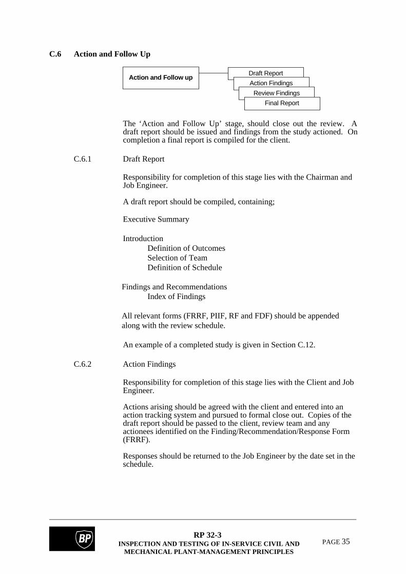
C.6 Action and Follow Up
Action and Follow upDraft Report
Action Findings
Review Findings
Final Report
The ‘Action and Follow Up’ stage, should close out the review. Adraft report should be issued and findings from the study actioned. Oncompletion a final report is compiled for the client.
C.6.1 Draft Report
Responsibility for completion of this stage lies with the Chairman andJob Engineer.
A draft report should be compiled, containing;
Executive Summary
IntroductionDefinition of OutcomesSelection of TeamDefinition of Schedule
Findings and RecommendationsIndex of Findings
All relevant forms (FRRF, PIIF, RF and FDF) should be appendedalong with the review schedule.
An example of a completed study is given in Section C.12.
C.6.2 Action Findings
Responsibility for completion of this stage lies with the Client and JobEngineer.
Actions arising should be agreed with the client and entered into anaction tracking system and pursued to formal close out. Copies of thedraft report should be passed to the client, review team and anyactionees identified on the Finding/Recommendation/Response Form(FRRF).
Responses should be returned to the Job Engineer by the date set in theschedule.

RP 32-3INSPECTION AND TESTING OF IN-SERVICE CIVIL AND
MECHANICAL PLANT-MANAGEMENT PRINCIPLES
PAGE 36
C.6.3 Review Findings
The review team shall meet to review the responses to the findingsraised. Any comments should be noted on the relevant FRRF.
C.6.4 Final Report
Once all the findings and responses have been accepted by the reviewteam, a final report should be compiled in a similar structure to that ofthe draft report. This final report should be signed by the Job Engineer,Chairman and relevant Endorsing Authority, as detailed below:-
C.6.4.1 Where the review recommends modifications to the writtenscheme of examination, or endorsement frequency, orgrading as per the anticipated outcomes the Inspection Groupleader should be the Endorsement Authority.
C.7 Plant Item Information Form
Responsibility for completion of this form lies with the Job Engineer, Process /Operations and Inspection Engineer.
All forms have been generated in a similar format. Each is subdivided into a numberof sections to be filled out by the relevant discipline engineer. Each section has a greyheader identifying the section title left and the engineer responsible for completion ofthat section on the right.
C.7.1 Common Details - Job Engineer
A description of the item or defined group of items should be notedand the TAG and WIN numbers for each item entered.
C.7.2 Normal Operation - Process / Operations Engineer
Inlet and outlet pressure and temperatures should be entered for the
plant item under normal operation.
C.7.3 Upset Conditions - Process / Operations Engineer Inlet and outlet pressure and temperatures should be entered for the
plant item during upset conditions. ‘Worst case’ upset conditionsshould be considered, during abnormal operation, commissioning ordecommissioning.
C.7.4 API RBI Level 1 Details - Process / Operations Engineer
This information is required to perform the API risk analysis. The
majority of questions require an answer from a pick list.
RP 32-3INSPECTION AND TESTING OF IN-SERVICE CIVIL AND
MECHANICAL PLANT-MANAGEMENT PRINCIPLES
PAGE 37
Representative Fluid - Defined as follows;
Light HC Process stream mainly C1-C5. Medium HC Process stream mainly C6-C16 Heavy HC Process stream mainly C16-C25+ Capacity - Defined as follows; Low Release will result in total deinventory of plant item.
Medium Release will result in total deinventory of plant item plus 1-10 others.
High Result will result in total deinventory of plant item plus 10+ others.
Business Interruption - Defined as follows; No SD No shutdown, little or no effect on throughput. Short SD 1-2 day shutdown, or reduced throughput. Extended SD 2+ day shutdown, or severely reduced throughput. Phase In the API model, this can only be selected as liquid or gas. If the fluid
exists in a two-phase state, as a worst case scenario, gas should beentered.
Percentage Toxicity The toxicity of the process stream expressed as a percentage.
Sold out Market Expressed as a yes / no dependant on whether the market is ‘sold out’.
C.7.5 TISCHUK Details - Process / Operations Engineer
This information is required to perform the TISCHUK risk analysis.As with the API the majority of questions require an answer from apick list.
Contents A description of the process stream should be entered, this should be
the same as the description of the process stream given on the relevantFDF.

RP 32-3INSPECTION AND TESTING OF IN-SERVICE CIVIL AND
MECHANICAL PLANT-MANAGEMENT PRINCIPLES
PAGE 38
Capacity - As with the API, this is defined as follows:- 0.227 m3 Release will result in total deinventory of plant item. 2.270 m3 Release will result in total deinventory of plant item
plus 1-10 others. 22.70 m3 Result will result in total deinventory of plant item plus
10+ others. Location Within Plant This provides a rough assessment of the hazard to personnel and to
other equipment. Defined as follows; 3 Inaccessible or infrequently visited, such as a sump. 2 General plant area. 1 Inside an enclosure such as a pump / compressor house. Phase In the TISCHUK model, this can be selected as liquid, two-phase or
gas. Financial Consequences This provides an estimate of the cost of failure of a line. Defined as
follows:-
3 Negligible total cost, less than 24 hours lost production orequivalent.
2 Moderate total cost, 1-7 days lost production or equivalent.1 High total cost, 7+ days lost production or equivalent.
Standby Availability This provides an assessment of the effect of a failure on the plant
operation. Defined as follows;
3 Allow the use of bypass or alternate production route.2 Cause operating problems or reduce throughput.1 Jeopardise plant operation or cause shutdown.
C.7.6 API RBI Level 1 Details - Inspection Engineer
This information is required to perform the API risk analysis. Themajority of questions require an answer from a pick list.
Material of Construction

RP 32-3INSPECTION AND TESTING OF IN-SERVICE CIVIL AND
MECHANICAL PLANT-MANAGEMENT PRINCIPLES
PAGE 39
The material of construction, must be selected from the following picklist;
Carbon SteelCarbon 1/2 Mo (Annealed)Carbon 1/2 Mo (Normalised)Cr 1/2 Mo (PWHT'd)1 1/4 Cr 1/2 Mo (PWHT'd)2 1/4 Cr 1/2 Mo (PWHT'd)Austenitic Stainless Steel300 Series Stainless321 Series Stainless347 Series StainlessH Grade StainlessL Grade StainlessAlloys 600Alloys 800Alloys 625Alloys 20
Years since last inspection
This should account for the year since the last inspection to the date atwhich the form was filled out. It is only necessary for this to beaccurate to the nearest year.
Deterioration Found
Expressed as a yes / no for each of the six mechanisms identified,dependant on any deterioration found.
C.7.7 TISCHUK - Static Equipment Details
This information is required to perform the TISCHUK risk analysis.
These questions do not require an answer from a pick list and can beentered as free text.
To determine nominal wall for heat exchanger tubebundles, convert the
BWG or SWG into wall thickness in mm.
C.8 Response Form
Responsibility for completion of this form lies with the core team members; JobEngineer, OCA Assessor Process / Operations, Inspection Engineer, CorrosionEngineer, Maintenance Engineer and Electrical / Instrument Engineer.

RP 32-3INSPECTION AND TESTING OF IN-SERVICE CIVIL AND
MECHANICAL PLANT-MANAGEMENT PRINCIPLES
PAGE 40
All forms have been generated in a similar format. Each is subdivided into a numberof sections to be filled out by the relevant discipline engineer. Each section has a greyheader identifying the section title left and the engineer responsible for completion ofthat section on the right.
C.8.1 Common Details - Job Engineer
A description of the item or defined group of items should be noted andthe TAG and WIN numbers for each item entered.
C.8.2 Criticality Analysis - OCA Assessor
Probability, Consequence and overall Criticality ratings should be
entered for the plant item or group of plant items and an indication ofthe driving factor given.
C.8.3 Operation / Process Factors - Process / Operations Engineer
The factors identified should be considered for the plant item or group
of plant items. If any comments are made, the box alongside therelevant factor should be blacked out and comments made alongside.Where a factor has been considered and no comment has been made,the box should be shaded grey.
C.8.4 Inspection Factors - Inspection Engineer
As for C.8.3
C.8.5 Corrosion Factors - Corrosion Engineer As for C.8.3
C.8.6 Maintenance Factors - Maintenance Engineer As for C 8.3
C.8.7 Electrical/Instrumentation Factors - Electrical/InstrumentationEngineer
As for C.8.3
C.9 Fluid Definition Form
Responsibility for completion of this form lies with the Job Engineer and Process /Operations Engineer.
The forms have been generated in a similar format. Each is subdivided into a numberof sections to be filled out by the relevant discipline engineer. Each section has a grey

RP 32-3INSPECTION AND TESTING OF IN-SERVICE CIVIL AND
MECHANICAL PLANT-MANAGEMENT PRINCIPLES
PAGE 41
header identifying the title of that section on the left and the engineer responsible forcompletion of that section on the right.
C.9.1 Common Details - Job Engineer
A description of distinct process stream should be entered. Forexample, ‘Water’ or ‘IC4 Recycle’.
C.9.2 Fluid Content - Process / Operations Engineer
The fluid content in terms of Water, H2S, CO2, Elemental Hydrogen,Sulphur, Chloride and Oxygen and Vapour Liquid Ratio should beexpressed in terms of the units given on the right side of the section;where known.
C.9.3 Fluid Makeup - Process / Operations Engineer
In order to identify the base fluids which make up the process streamfrom the picklist given, the box to the right of each of the relevantfluids should be blacked out.

RP 32-3INSPECTION AND TESTING OF IN-SERVICE CIVIL AND
MECHANICAL PLANT-MANAGEMENT PRINCIPLES
PAGE 42
C.10 Guide phrases/words in matrix formatIT
EM
RE
PA
IRS
?H
AZ
OP
?P
HS
ER
?P
MP
?M
AT
L o
f C
ON
ST
RN
FL
UID
?C
OM
PO
SIT
ION
?F
LO
W?
PR
ES
S?
TE
MP
?L
EV
EL
?R
EA
CT
ION
?
Page 1 of 2

RP 32-3INSPECTION AND TESTING OF IN-SERVICE CIVIL AND
MECHANICAL PLANT-MANAGEMENT PRINCIPLES
PAGE 43
ITE
MP
OW
ER
?C
OR
RO
SIO
N?
EM
ISS
ION
S?
ST
AR
T U
P?
SH
UT
DO
WN
?N
OR
MA
L C
ON
DS
?U
PS
ET
CO
ND
S?
MA
INT
EN
AN
CE
?O
TH
ER
?
Page 2 of 2
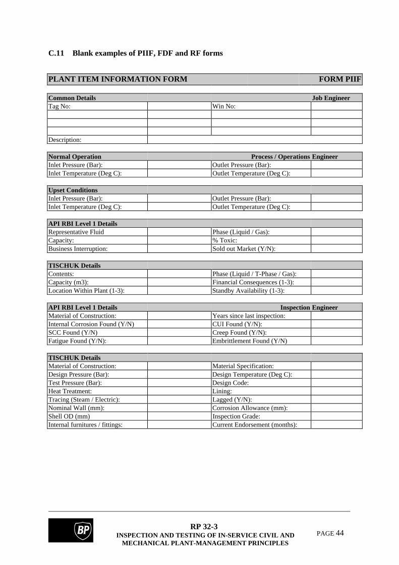
RP 32-3INSPECTION AND TESTING OF IN-SERVICE CIVIL AND
MECHANICAL PLANT-MANAGEMENT PRINCIPLES
PAGE 44
C.11 Blank examples of PIIF, FDF and RF forms
PLANT ITEM INFORMATION FORM FORM PIIF
Common Details Job EngineerTag No: Win No:
Description:
Normal Operation Process / OperationsEngineerInlet Pressure (Bar): Outlet Pressure (Bar):Inlet Temperature (Deg C): Outlet Temperature (Deg C):
Upset ConditionsInlet Pressure (Bar): Outlet Pressure (Bar):Inlet Temperature (Deg C): Outlet Temperature (Deg C):
API RBI Level 1 DetailsRepresentative Fluid Phase (Liquid / Gas):Capacity: % Toxic:Business Interruption: Sold out Market (Y/N):
TISCHUK DetailsContents: Phase (Liquid / T-Phase / Gas):Capacity (m3): Financial Consequences (1-3):Location Within Plant (1-3): Standby Availability (1-3):
API RBI Level 1 Details Inspection EngineerMaterial of Construction: Years since last inspection:Internal Corrosion Found (Y/N) CUI Found (Y/N):SCC Found (Y/N) Creep Found (Y/N):Fatigue Found (Y/N): Embrittlement Found (Y/N)
TISCHUK DetailsMaterial of Construction: Material Specification:Design Pressure (Bar): Design Temperature (Deg C):Test Pressure (Bar): Design Code:Heat Treatment: Lining:Tracing (Steam / Electric): Lagged (Y/N):Nominal Wall (mm): Corrosion Allowance (mm):Shell OD (mm) Inspection Grade:Internal furnitures / fittings: Current Endorsement (months):
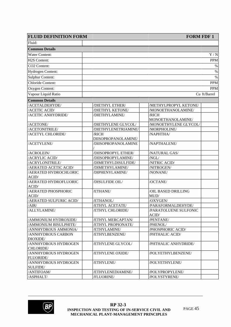
RP 32-3INSPECTION AND TESTING OF IN-SERVICE CIVIL AND
MECHANICAL PLANT-MANAGEMENT PRINCIPLES
PAGE 45
FLUID DEFINITION FORM FORM FDF 1Fluid:
Common DetailsWater Content: Y / N
H2S Content: PPM
CO2 Content: %
Hydrogen Content: %
Sulphur Content: %
Chloride Content: PPM
Oxygen Content: PPM
Vapour Liquid Ratio Cu ft/Barrel
Common Details/ACETALDEHYDE/ /DIETHYL ETHER/ /METHYLPROPYL KETONE//ACETIC ACID/ /DIETHYL KETONE/ /MONOETHANOLAMINE//ACETIC ANHYDRIDE/ /DIETHYLAMINE/ /RICH
MONOETHANOLAMINE//ACETONE/ /DIETHYLENE GLYCOL/ /MONOETHYLENE GLYCOL//ACETONITRILE/ /DIETHYLENETRIAMINE/ /MORPHOLINE//ACETYL CHLORIDE/ /RICH
DIISOPROPANOLAMINE//NAPHTHA/
/ACETYLENE/ /DIISOPROPANOLAMINE/
/NAPTHALENE/
/ACROLEIN/ /DIISOPROPYL ETHER/ /NATURAL GAS//ACRYLIC ACID/ /DIISOPROPYLAMINE/ /NGL//ACRYLONITRILE/ /DIMETHYLDISULFIDE/ /NITRIC ACID//AERATED ACETIC ACID/ /DIMETHYLAMINE/ /NITROGEN//AERATED HYDROCHLORICACID/
/DIPHENYLAMINE/ /NONANE/
/AERATED HYDROFLUORICACID/
/DISULFIDE OIL/ /OCTANE/
/AERATED PHOSPHORICACID/
/ETHANE/ /OIL BASED DRILLINGMUD/
/AERATED SULFURIC ACID/ /ETHANOL/ /OXYGEN//AIR/ /ETHYL ACETATE/ /PARAFORMALDEHYDE//ALLYLAMINE/ /ETHYL CHLORIDE/ /PARATOLUENE SULFONIC
ACID//AMMONIUM HYDROXIDE/ /ETHYL MERCAPTAN/ /PENTANE//AMMONIUM BISULPHITE/ /ETHYL PROPIONATE/ /PHENOL//ANNHYDROUS AMMONIA/ /ETHYLAMINE/ /PHOSPHORIC ACID//ANNHYDROUS CARBONDIOXIDE/
/ETHYLBENZENE/ /PHTHALIC ACID/
/ANNHYDROUS HYDROGENCHLORIDE/
/ETHYLENE GLYCOL/ /PHTHALIC ANHYDRIDE/
/ANNHYDROUS HYDROGENFLUORIDE/
/ETHYLENE OXIDE/ /POLYETHYLBENZENE/
/ANNHYDROUS HYDROGENSULFIDE/
/ETHYLENE/ /POLYETHYLENE/
/ANTIFOAM/ /ETHYLENEDIAMINE/ /POLYPROPYLENE//ASPHALT/ /FLUORINE/ /POLYSTYRENE/

RP 32-3INSPECTION AND TESTING OF IN-SERVICE CIVIL AND
MECHANICAL PLANT-MANAGEMENT PRINCIPLES
PAGE 46
FLUID DEFINITION FOR M FORM FDF 2/BENZENE/ /FORMALDEHYDE/ /POTASSIUM HYDROXIDE//BENZOIC ACID/ /FORMIC ACID/ /PROPANE//BENZYL ACETATE/ /FREON/ /PROPANOL//BENZYL ALCOHOL/ /FUEL OIL/ /PROPIONALDEHYDE//BENZYL CHLORIDE/ /FURFURAL/ /PROPIONIC ACID/BROMINE/ /GASOIL/ /PROPYL ACETATE//BUTADIENE/ /GASOLINE/ /PROPYLENE GLYCOL//BUTANE/ /GLUTERALDEHYDE/ /PROPYLENE OXIDE//BUTANOL/ /HALON/ /PROPYLENE//BUTENE/ /HEAT TRANSFER OIL/ /SALT//BUTYL ACETATE/ /HEAVY FUEL OIL/ /SCALE INHIBITOR//BUTYLENE/ /HEPTANE/ /SEAWATER//BUTYRIC ACID/ /HEXANE/ /SHORT RESIDUE//C1/ /HEXANOL/ /SODIUM BICARBONATE//C10/ /HYDRAULIC FLUID/ /SODIUM HYPOCHLORITE//C12/ /HYDRAULIC OIL/ /STEAM//C15/ /HYDRAZINE/ /STYRENE//C2/ /HYDROBROMIC ACID/ /SULFOLANE//C20/ /HYDROCHLORIC ACID/ /SULFUR DIOXIDE//C3/ /HYDROFLUORIC ACID/ /SULFUR TRIOXIDE//C4/ /HYDROGEN CYANIDE/ /SULFUR//C5/ /HYDROGEN PEROXIDE/ /SULFURIC ACID//C6/ /HYDROGEN SULFIDE/ /SULFUROUS ACID//C7/ /HYDROGEN/ /TETRAETHYL LEAD//C8/ /HYDROQUINONE/ /TETRAETHYLENE
GLYCOL//C9/ /ISOBUTANE/ /TOLUENE//CALCIUM CHLORIDE/ /ISOBUTANOL/ /TOPANOL//CARBON DIOXIDE/ /ISOBUTYL ACETATE/ /TRIBUTYLAMINE//CARBON DISULFIDE/ /ISOHEXANE/ /TRICHLOROETHANE//CARBON MONOXIDE/ /ISOOCTANE/ /TRICHLOROETHYLENE//CARBON TETRACHLORIDE/ /ISOPENTANE/ /TRIETHANOLAMINE//CAUSTIC/ /ISOPHORONE/ /TRIETHYLAMINE//CHLORINE/ /ISOPROPANOL/ /TRIETHYLENE GLYCOL//CITRIC ACID/ /ISOPROPANOLAMINE/ /TRIISOPROPANOLAMINE//CORROSION INHIBITOR/ /ISOPROPYL ACETATE/ /TRIMETHYLAMINE//CRUDE OIL/ /ISOPROPYL ETHER/ /VINYL ACETATE//CUMENE/ /KEROSENE/ /VINYL CHLORIDE//CYCLOHEXANE/ /LIQUIFIED PETROLEUM
GAS//WATER BASED DRILLINGMUD/
/CYCLOPENTANE/ /LONG RESIDUE/ /WATER//DEAERATED SEAWATER/ /LPG/ /XYLENE//DECANE/ /LUBE OIL/ /METHYL IODIDE//DEMULSIFIER/ /METHANE/ /ETHYLIDENE DIACETATE//DETERGENT/ /METHANOL/ /RHODIUM ACETATE//DIBUTYLAMINE/ /METHYL ACETATE/ /LITHIUM ACETATE//DIESEL/ /METHYL PROPIONATE/ /IMIDAZOLE//RICH DIETHANOLAMINE/ /METHYLBUTYL
KETONE//A5 POLYMER/
/DIETHANOLAMINE/ /METHYLETHYLKETONE/

RP 32-3INSPECTION AND TESTING OF IN-SERVICE CIVIL AND
MECHANICAL PLANT-MANAGEMENT PRINCIPLES
PAGE 47
RESPONSE FORM FORM RF (1)
Common Details Job EngineerTag No: Win No:
Description:
Criticality Analysis OCA AssessorProbability ratingConsequence ratingCriticality rating
Operations / Process Factors Process/Operations EngineerOperation historyImpact on unit operationImpact on other unitsImpact on personnelPotential for foulingOperational windowFluid qualityUpset conditionsIsolation / Gas freeingOther
Inspection Factors Inspection EngineerInspection historyGeneral / local wastageIsolated / multiple pittingSurface / embedded cracksMicrostructural changeDelaminationUltrasonicRadiographyDPIMPIAdditional NDT techniquesDesign suitable for NDTEndorsement frequencyWeldabilityWelding ProcedurePost Weld Heat TreatedRepair considerationsOther

RP 32-3INSPECTION AND TESTING OF IN-SERVICE CIVIL AND
MECHANICAL PLANT-MANAGEMENT PRINCIPLES
PAGE 48
RESPONSE FORM FORM RF (2)
Corrosion Factors Corrosion EngineerInternal CorrosionCUISCCCreepFatigueEmbrittlementPCMS DataCorrosion PreventionMaterial ConsiderationsOther
Maintenance Factors Maintenance EngineerAccessibilitySparing / AvailabilityItem reliabilityRoutine maintenanceOther
Electrical / Instrumentation Factors Electrical/Instrumentation EngineerTrip TestingCV'sOther
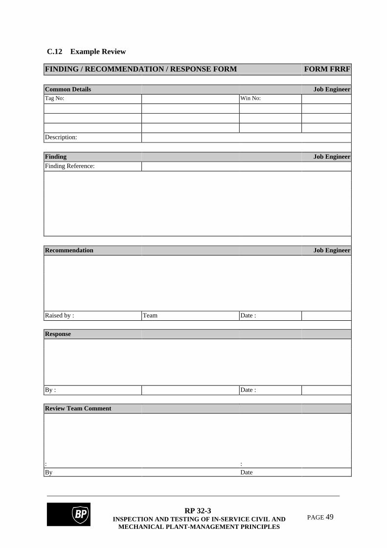
RP 32-3INSPECTION AND TESTING OF IN-SERVICE CIVIL AND
MECHANICAL PLANT-MANAGEMENT PRINCIPLES
PAGE 49
C.12 Example Review
FINDING / RECOMMENDATION / RESPONSE FORM FORM FRRF
Common Details Job EngineerTag No: Win No:
Description:
Finding Job EngineerFinding Reference:
Recommendation Job Engineer
Raised by : Team Date :
Response
By : Date :
Review Team Comment
: :By Date