rozup.irrozup.ir/up/joorvajoor/EBOOK/Solutions Shigley’s Mechanical...Chapter 1 Problems 1-1...
455
Chapter 1 Problems 1-1 through 1-4 are for student research. 1-5 (a) Point vehicles Q = cars hour = v x = 42.1v − v 2 0.324 Seek stationary point maximum dQ d v = 0 = 42.1 − 2v 0.324 ∴ v* = 21.05 mph Q* = 42.1(21.05) − 21.05 2 0.324 = 1368 cars/h Ans. (b) Q = v x + l = 0.324 v(42.1) − v 2 + l v −1 Maximize Q with l = 10/5280 mi v Q 22.18 1221.431 22.19 1221.433 22.20 1221.435 ← 22.21 1221.435 22.22 1221.434 % loss of throughput = 1368 − 1221 1221 = 12% Ans. (c) % increase in speed 22.2 − 21.05 21.05 = 5.5% Modest change in optimal speed Ans. x l 2 l 2 v x v
-
Upload
nguyenkiet -
Category
Documents
-
view
231 -
download
9
Transcript of rozup.irrozup.ir/up/joorvajoor/EBOOK/Solutions Shigley’s Mechanical...Chapter 1 Problems 1-1...

Chapter 1
Problems 1-1 through 1-4 are for student research.
1-5
(a) Point vehicles
Q = cars
hour= v
x= 42.1v − v2
0.324Seek stationary point maximum
d Q
dv= 0 = 42.1 − 2v
0.324∴ v* = 21.05 mph
Q* = 42.1(21.05) − 21.052
0.324= 1368 cars/h Ans.
(b)
Q = v
x + l=
(0.324
v(42.1) − v2+ l
v
)−1
Maximize Q with l = 10/5280 mi
v Q
22.18 1221.43122.19 1221.43322.20 1221.435 ←22.21 1221.43522.22 1221.434
% loss of throughput = 1368 − 1221
1221= 12% Ans.
(c) % increase in speed 22.2 − 21.05
21.05= 5.5%
Modest change in optimal speed Ans.
xl2
l2
v
x
v
budy_sm_ch01.qxd 11/21/2006 15:23 Page 1

2 Solutions Manual • Instructor’s Solution Manual to Accompany Mechanical Engineering Design
1-6 This and the following problem may be the student’s first experience with a figure of merit.
• Formulate fom to reflect larger figure of merit for larger merit.• Use a maximization optimization algorithm. When one gets into computer implementa-
tion and answers are not known, minimizing instead of maximizing is the largest errorone can make. ∑
FV = F1 sin θ − W = 0∑FH = −F1 cos θ − F2 = 0
From which
F1 = W/sin θ
F2 = −W cos θ/sin θ
fom = −$ = −¢γ (volume).= −¢γ(l1 A1 + l2 A2)
A1 = F1
S= W
S sin θ, l2 = l1
cos θ
A2 =∣∣∣∣ F2
S
∣∣∣∣ = W cos θ
S sin θ
fom = −¢γ
(l2
cos θ
W
S sin θ+ l2W cos θ
S sin θ
)
= −¢γ Wl2
S
(1 + cos2 θ
cos θ sin θ
)
Set leading constant to unity
θ◦ fom
0 −∞20 −5.8630 −4.0440 −3.2245 −3.0050 −2.8754.736 −2.82860 −2.886
Check second derivative to see if a maximum, minimum, or point of inflection has beenfound. Or, evaluate fom on either side of θ*.
θ* = 54.736◦ Ans.fom* = −2.828
Alternative:
d
dθ
(1 + cos2 θ
cos θ sin θ
)= 0
And solve resulting tran-scendental for θ*.
budy_sm_ch01.qxd 11/21/2006 15:23 Page 2

Chapter 1 3
1-7(a) x1 + x2 = X1 + e1 + X2 + e2
error = e = (x1 + x2) − (X1 + X2)= e1 + e2 Ans.
(b) x1 − x2 = X1 + e1 − (X2 + e2)e = (x1 − x2) − (X1 − X2) = e1 − e2 Ans.
(c) x1x2 = (X1 + e1)(X2 + e2)
e = x1x2 − X1 X2 = X1e2 + X2e1 + e1e2
.= X1e2 + X2e1 = X1 X2
(e1
X1+ e2
X2
)Ans.
(d)x1
x2= X1 + e1
X2 + e2= X1
X2
(1 + e1/X1
1 + e2/X2
)(
1 + e2
X2
)−1.= 1 − e2
X2and
(1 + e1
X1
)(1 − e2
X2
).= 1 + e1
X1− e2
X2
e = x1
x2− X1
X2
.= X1
X2
(e1
X1− e2
X2
)Ans.
1-8(a) x1 =
√5 = 2.236 067 977 5
X1 = 2.23 3-correct digits
x2 =√
6 = 2.449 487 742 78
X2 = 2.44 3-correct digits
x1 + x2 =√
5 +√
6 = 4.685 557 720 28
e1 = x1 − X1 =√
5 − 2.23 = 0.006 067 977 5
e2 = x2 − X2 =√
6 − 2.44 = 0.009 489 742 78
e = e1 + e2 =√
5 − 2.23 +√
6 − 2.44 = 0.015 557 720 28
Sum = x1 + x2 = X1 + X2 + e= 2.23 + 2.44 + 0.015 557 720 28= 4.685 557 720 28 (Checks) Ans.
(b) X1 = 2.24, X2 = 2.45
e1 =√
5 − 2.24 = −0.003 932 022 50
e2 =√
6 − 2.45 = −0.000 510 257 22
e = e1 + e2 = −0.004 442 279 72
Sum = X1 + X2 + e= 2.24 + 2.45 + (−0.004 442 279 72)= 4.685 557 720 28 Ans.
budy_sm_ch01.qxd 11/21/2006 15:23 Page 3

4 Solutions Manual • Instructor’s Solution Manual to Accompany Mechanical Engineering Design
1-9
(a) σ = 20(6.89) = 137.8 MPa
(b) F = 350(4.45) = 1558 N = 1.558 kN
(c) M = 1200 lbf · in (0.113) = 135.6 N · m
(d) A = 2.4(645) = 1548 mm2
(e) I = 17.4 in4 (2.54)4 = 724.2 cm4
(f) A = 3.6(1.610)2 = 9.332 km2
(g) E = 21(1000)(6.89) = 144.69(103) MPa = 144.7 GPa
(h) v = 45 mi/h (1.61) = 72.45 km/h(i) V = 60 in3 (2.54)3 = 983.2 cm3 = 0.983 liter
1-10(a) l = 1.5/0.305 = 4.918 ft = 59.02 in(b) σ = 600/6.89 = 86.96 kpsi(c) p = 160/6.89 = 23.22 psi(d) Z = 1.84(105)/(25.4)3 = 11.23 in3
(e) w = 38.1/175 = 0.218 lbf/in(f) δ = 0.05/25.4 = 0.00197 in(g) v = 6.12/0.0051 = 1200 ft /min(h) ε = 0.0021 in/in(i) V = 30/(0.254)3 = 1831 in3
1-11
(a) σ = 200
15.3= 13.1 MPa
(b) σ = 42(103)
6(10−2)2= 70(106) N/m2 = 70 MPa
(c) y = 1200(800)3(10−3)3
3(207)109(64)103(10−3)4= 1.546(10−2) m = 15.5 mm
(d) θ = 1100(250)(10−3)
79.3(109)(π/32)(25)4(10−3)4= 9.043(10−2) rad = 5.18◦
1-12
(a) σ = 600
20(6)= 5 MPa
(b) I = 1
128(24)3 = 9216 mm4
(c) I = π
64324(10−1)4 = 5.147 cm4
(d) τ = 16(16)
π(253)(10−3)3= 5.215(106) N/m2 = 5.215 MPa
budy_sm_ch01.qxd 11/21/2006 15:23 Page 4

Chapter 1 5
1-13
(a) τ = 120(103)
(π/4)(202)= 382 MPa
(b) σ = 32(800)(800)(10−3)
π(32)3(10−3)3= 198.9(106) N/m2 = 198.9 MPa
(c) Z = π
32(36)(364 − 264) = 3334 mm3
(d) k = (1.6)4 (10−3)4(79.3)(109)
8(19.2)3(10−3)3(32)= 286.8 N/m
budy_sm_ch01.qxd 11/21/2006 15:23 Page 5

FIRST PAGES
2-1 From Table A-20
Sut = 470 MPa (68 kpsi) , Sy = 390 MPa (57 kpsi) Ans.
2-2 From Table A-20
Sut = 620 MPa (90 kpsi) , Sy = 340 MPa (49.5 kpsi) Ans.
2-3 Comparison of yield strengths:
Sut of G10 500 HR is 620
470= 1.32 times larger than SAE1020 CD Ans.
Syt of SAE1020 CD is 390
340= 1.15 times larger than G10500 HR Ans.
From Table A-20, the ductilities (reduction in areas) show,
SAE1020 CD is 40
35= 1.14 times larger than G10500 Ans.
The stiffness values of these materials are identical Ans.
Table A-20 Table A-5Sut Sy Ductility Stiffness
MPa (kpsi) MPa (kpsi) R% GPa (Mpsi)
SAE1020 CD 470(68) 390 (57) 40 207(30)UNS10500 HR 620(90) 340(495) 35 207(30)
2-4 From Table A-21
1040 Q&T Sy = 593 (86) MPa (kpsi) at 205◦C (400◦F) Ans.
2-5 From Table A-21
1040 Q&T R = 65% at 650◦C (1200◦F) Ans.
2-6 Using Table A-5, the specific strengths are:
UNS G10350 HR steel:Sy
W= 39.5(103)
0.282= 1.40(105) in Ans.
2024 T4 aluminum:Sy
W= 43(103)
0.098= 4.39(105) in Ans.
Ti-6Al-4V titanium:Sy
W= 140(103)
0.16= 8.75(105) in Ans.
ASTM 30 gray cast iron has no yield strength. Ans.
Chapter 2
budynas_SM_ch02.qxd 11/22/2006 16:28 Page 6

FIRST PAGES
Chapter 2 7
2-7 The specific moduli are:
UNS G10350 HR steel:E
W= 30(106)
0.282= 1.06(108) in Ans.
2024 T4 aluminum:E
W= 10.3(106)
0.098= 1.05(108) in Ans.
Ti-6Al-4V titanium:E
W= 16.5(106)
0.16= 1.03(108) in Ans.
Gray cast iron:E
W= 14.5(106)
0.26= 5.58(107) in Ans.
2-8 2G(1 + ν) = E ⇒ ν = E − 2G
2G
From Table A-5
Steel: ν = 30 − 2(11.5)
2(11.5)= 0.304 Ans.
Aluminum: ν = 10.4 − 2(3.90)
2(3.90)= 0.333 Ans.
Beryllium copper: ν = 18 − 2(7)
2(7)= 0.286 Ans.
Gray cast iron: ν = 14.5 − 2(6)
2(6)= 0.208 Ans.
2-9
0
10
0 0.0020.1
0.0040.2
0.0060.3
0.0080.4
0.0100.5
0.0120.6
0.0140.7
0.0160.8
(Lower curve)(Upper curve)
20
30
40
50
Stre
ss P
�A0
kpsi
Strain, �
60
70
80
E
Y
U
Su � 85.5 kpsi Ans.
E � 90�0.003 � 30 000 kpsi Ans.
Sy � 45.5 kpsi Ans.
R � (100) � 45.8% Ans.A0 � AF
A0�
0.1987 � 0.10770.1987
� ��ll0
�l � l0
l0
ll0
� � 1A
A0� � 1
budynas_SM_ch02.qxd 11/22/2006 16:28 Page 7

FIRST PAGES
8 Solutions Manual • Instructor’s Solution Manual to Accompany Mechanical Engineering Design
2-10 To plot σtrue vs. ε, the following equations are applied to the data.
A0 = π(0.503)2
4= 0.1987 in2
Eq. (2-4) ε = lnl
l0for 0 ≤ �L ≤ 0.0028 in
ε = lnA0
Afor �L > 0.0028 in
σtrue = P
A
The results are summarized in the table below and plotted on the next page.The last 5 points of data are used to plot log σ vs log ε
The curve fit gives m = 0.2306
log σ0 = 5.1852 ⇒ σ0 = 153.2 kpsiAns.
For 20% cold work, Eq. (2-10) and Eq. (2-13) give,
A = A0(1 − W ) = 0.1987(1 − 0.2) = 0.1590 in2
ε = lnA0
A= ln
0.1987
0.1590= 0.2231
Eq. (2-14):
S′y = σ0ε
m = 153.2(0.2231)0.2306 = 108.4 kpsi Ans.
Eq. (2-15), with Su = 85.5 kpsi from Prob. 2-9,
S′u = Su
1 − W= 85.5
1 − 0.2= 106.9 kpsi Ans.
P �L A ε σtrue log ε log σtrue
0 0 0.198 713 0 01000 0.0004 0.198 713 0.0002 5032.388 −3.69901 3.701 7742000 0.0006 0.198 713 0.0003 10064.78 −3.52294 4.002 8043000 0.0010 0.198 713 0.0005 15097.17 −3.30114 4.178 8954000 0.0013 0.198 713 0.00065 20129.55 −3.18723 4.303 8347000 0.0023 0.198 713 0.001149 35226.72 −2.93955 4.546 8728400 0.0028 0.198 713 0.001399 42272.06 −2.85418 4.626 0538800 0.0036 0.1984 0.001575 44354.84 −2.80261 4.646 9419200 0.0089 0.1978 0.004604 46511.63 −2.33685 4.667 5629100 0.1963 0.012216 46357.62 −1.91305 4.666 121
13200 0.1924 0.032284 68607.07 −1.49101 4.836 36915200 0.1875 0.058082 81066.67 −1.23596 4.908 84217000 0.1563 0.240083 108765.2 −0.61964 5.0364916400 0.1307 0.418956 125478.2 −0.37783 5.098 56814800 0.1077 0.612511 137418.8 −0.21289 5.138 046
budynas_SM_ch02.qxd 11/22/2006 16:28 Page 8

FIRST PAGES
Chapter 2 9
2-11 Tangent modulus at σ = 0 is
E0 = �σ
�ε
.= 5000 − 0
0.2(10−3) − 0= 25(106) psi
At σ = 20 kpsi
E20.= (26 − 19)(103)
(1.5 − 1)(10−3)= 14.0(106) psi Ans.
ε(10−3) σ (kpsi)
0 00.20 50.44 100.80 161.0 191.5 262.0 322.8 403.4 464.0 495.0 54
log �
log
�y � 0.2306x � 5.1852
4.8
4.9
5
5.1
5.2
�1.6 �1.4 �1.2 �1 �0.8 �0.6 �0.4 �0.2 0
�true
�tr
ue (
psi)
0
20000
40000
60000
80000
100000
120000
140000
160000
0 0.1 0.2 0.3 0.4 0.5 0.6 0.7
� (10�3)
(Sy)0.001 � 35 kpsi Ans.
� (
kpsi
)
0
10
20
30
40
50
60
0 1 2 3 4 5
budynas_SM_ch02.qxd 11/22/2006 16:28 Page 9

FIRST PAGES
10 Solutions Manual • Instructor’s Solution Manual to Accompany Mechanical Engineering Design
2-12 Since |εo| = |εi | ∣∣∣∣ln R + h
R + N
∣∣∣∣ =∣∣∣∣ln R
R + N
∣∣∣∣ =∣∣∣∣−ln
R + N
R
∣∣∣∣R + h
R + N= R + N
R
(R + N )2 = R(R + h)
From which, N 2 + 2RN − Rh = 0
The roots are: N = R
[−1 ±
(1 + h
R
)1/2]
The + sign being significant,
N = R
[(1 + h
R
)1/2
− 1
]Ans.
Substitute for N in
εo = lnR + h
R + N
Gives ε0 = ln
R + h
R + R
(1 + h
R
)1/2
− R
= ln
(1 + h
R
)1/2
Ans.
These constitute a useful pair of equations in cold-forming situations, allowing the surfacestrains to be found so that cold-working strength enhancement can be estimated.
2-13 From Table A-22
AISI 1212 Sy = 28.0 kpsi, σ f = 106 kpsi, Sut = 61.5 kpsi
σ0 = 110 kpsi, m = 0.24, ε f = 0.85
From Eq. (2-12) εu = m = 0.24
Eq. (2-10)A0
A′i
= 1
1 − W= 1
1 − 0.2= 1.25
Eq. (2-13) εi = ln 1.25 = 0.2231 ⇒ εi < εu
Eq. (2-14) S′y = σ0ε
mi = 110(0.2231)0.24 = 76.7 kpsi Ans.
Eq. (2-15) S′u = Su
1 − W= 61.5
1 − 0.2= 76.9 kpsi Ans.
2-14 For HB = 250,
Eq. (2-17) Su = 0.495 (250) = 124 kpsi
= 3.41 (250) = 853 MPaAns.
budynas_SM_ch02.qxd 11/22/2006 16:28 Page 10

FIRST PAGES
Chapter 2 11
2-15 For the data given,∑
HB = 2530∑
H2B = 640 226
HB = 2530
10= 253 σH B =
√640 226 − (2530)2/10
9= 3.887
Eq. (2-17)Su = 0.495(253) = 125.2 kpsi Ans.
σsu = 0.495(3.887) = 1.92 kpsi Ans.
2-16 From Prob. 2-15, HB = 253 and σHB = 3.887
Eq. (2-18)
Su = 0.23(253) − 12.5 = 45.7 kpsi Ans.
σsu = 0.23(3.887) = 0.894 kpsi Ans.
2-17 (a) u R
.= 45.52
2(30)= 34.5 in · lbf/in3 Ans.
(b)
P �L A A0/A − 1 ε σ = P/A0
0 0 0 01 000 0.0004 0.0002 5 032.392 000 0.0006 0.0003 10 064.783 000 0.0010 0.0005 15 097.174 000 0.0013 0.000 65 20 129.557 000 0.0023 0.00115 35 226.728 400 0.0028 0.0014 42 272.068 800 0.0036 0.0018 44 285.029 200 0.0089 0.004 45 46 297.979 100 0.1963 0.012 291 0.012 291 45 794.73
13 200 0.1924 0.032 811 0.032 811 66 427.5315 200 0.1875 0.059 802 0.059 802 76 492.3017 000 0.1563 0.271 355 0.271 355 85 550.6016 400 0.1307 0.520 373 0.520 373 82 531.1714 800 0.1077 0.845059 0.845 059 74 479.35
budynas_SM_ch02.qxd 11/22/2006 16:28 Page 11

FIRST PAGES
12 Solutions Manual • Instructor’s Solution Manual to Accompany Mechanical Engineering Design
uT.=
5∑i=1
Ai = 1
2(43 000)(0.001 5) + 45 000(0.004 45 − 0.001 5)
+ 1
2(45 000 + 76 500)(0.059 8 − 0.004 45)
+ 81 000(0.4 − 0.059 8) + 80 000(0.845 − 0.4)
.= 66.7(103)in · lbf/in3 Ans.
�
�
0
20000
10000
30000
40000
50000
60000
70000
80000
90000
0 0.2 0.4 0.6 0.8
A3
A4 A5
Last 6 data points
First 9 data points
�
�
0
A1 A215000
10000
5000
20000
25000
30000
35000
40000
45000
50000
0 0.0020.001 0.003 0.004 0.005
�
�
0
20000
10000
30000
40000
50000
60000
70000
80000
90000
0 0.2 0.4
All data points0.6 0.8
budynas_SM_ch02.qxd 11/22/2006 16:28 Page 12

FIRST PAGES
Chapter 2 13
2-18 m = Alρ
For stiffness, k = AE/ l, or, A = kl/E .
Thus, m = kl2ρ/E , and, M = E/ρ. Therefore, β = 1
From Fig. 2-16, ductile materials include Steel, Titanium, Molybdenum, Aluminum, andComposites.
For strength, S = F/A, or, A = F/S.
Thus, m = Fl ρ/S, and, M = S/ρ.
From Fig. 2-19, lines parallel to S/ρ give for ductile materials, Steel, Nickel, Titanium, andcomposites.
Common to both stiffness and strength are Steel, Titanium, Aluminum, and Composites. Ans.
budynas_SM_ch02.qxd 11/22/2006 16:28 Page 13
ICCP1_60
2-18
ICCP1_60
Au.: We have changed the number from "2-22" to "2-18" for correct sequence. Please suggest.

FIRST PAGES
Chapter 3
3-1
1
RC
RARB
RD
C
A B
W
D
1
23
RB
RA
W
RB
RC
RA
2
1
W
RA
RBx
RBx RBy
RBy
RB
2
1
1
Scale ofcorner magnified
W
A
B
(e)
(f)
(d)
W
A
RA RB
B
1
2
W
A
RA RB
B
11
2
(a) (b)
(c)
budynas_SM_ch03.qxd 11/28/2006 21:21 Page 14

FIRST PAGES
Chapter 3 15
3-2(a) RA = 2 sin 60 = 1.732 kN Ans.
RB = 2 sin 30 = 1 kN Ans.
(b) S = 0.6 m
α = tan−1 0.6
0.4 + 0.6= 30.96◦
RA
sin 135= 800
sin 30.96⇒ RA = 1100 N Ans.
RO
sin 14.04= 800
sin 30.96⇒ RO = 377 N Ans.
(c)RO = 1.2
tan 30= 2.078 kN Ans.
RA = 1.2
sin 30= 2.4 kN Ans.
(d) Step 1: Find RA and RE
h = 4.5
tan 30= 7.794 m
� +∑
MA = 0
9RE − 7.794(400 cos 30) − 4.5(400 sin 30) = 0
RE = 400 N Ans.
∑Fx = 0 RAx + 400 cos 30 = 0 ⇒ RAx = −346.4 N∑Fy = 0 RAy + 400 − 400 sin 30 = 0 ⇒ RAy = −200 N
RA =√
346.42 + 2002 = 400 N Ans.
D
C
h
B
y
E xA
4.5 m
9 m
400 N
3
42
30°
60°
RAy
RA
RAx
RE
1.2 kN
60°
RA
RO
60°90°
30°
1.2 kN
RARO
45� � 30.96� � 14.04�
135°
30.96°
30.96°
800 N
RA
RO
O
0.4 m
45°
800 N
�
0.6 m
A
s
RA
RO
B
60°
90°
30°
2 kN
RA
RB
2
1
2 kN
60°30°
RA
RB
budynas_SM_ch03.qxd 11/28/2006 21:21 Page 15

FIRST PAGES
16 Solutions Manual • Instructor’s Solution Manual to Accompany Mechanical Engineering Design
Step 2: Find components of RC on link 4 and RD
�+∑
MC = 0
400(4.5) − (7.794 − 1.9)RD = 0 ⇒ RD = 305.4 N Ans.∑Fx = 0 ⇒ (RCx )4 = 305.4 N∑Fy = 0 ⇒ (RCy)4 = −400 N
Step 3: Find components of RC on link 2∑Fx = 0
(RCx )2 + 305.4 − 346.4 = 0 ⇒ (RCx )2 = 41 N∑Fy = 0
(RCy)2 = 200 N
3-3(a)
� +∑
M0 = 0
−18(60) + 14R2 + 8(30) − 4(40) = 0
R2 = 71.43 lbf∑Fy = 0: R1 − 40 + 30 + 71.43 − 60 = 0
R1 = −1.43 lbf
M1 = −1.43(4) = −5.72 lbf · inM2 = −5.72 − 41.43(4) = −171.44 lbf · inM3 = −171.44 − 11.43(6) = −240 lbf · inM4 = −240 + 60(4) = 0 checks!
4" 4" 6" 4"
�1.43�41.43
�11.43
60
40 lbf 60 lbf
30 lbf
x
x
x
OA B C D
y
R1 R2
M1
M2 M3
M4
O
V (lbf)
M(lbf • in)
O
CC
DB
A
B D
E
305.4 N
346.4 N
305.4 N
41 N
400 N
200 N400 N
200 N
400 N
Pin C30°
305.4 N
400 N
400 N200 N
41 N
305.4 N
200 N
346.4 N
305.4 N
(RCx)2
(RCy)2
C
B
A
2
400 N
4
RD
(RCx)4
(RCy)4
D
C
E
Ans.
budynas_SM_ch03.qxd 11/28/2006 21:21 Page 16

FIRST PAGES
Chapter 3 17
(b)∑
Fy = 0
R0 = 2 + 4(0.150) = 2.6 kN∑M0 = 0
M0 = 2000(0.2) + 4000(0.150)(0.425)
= 655 N · m
M1 = −655 + 2600(0.2) = −135 N · m
M2 = −135 + 600(0.150) = −45 N · m
M3 = −45 + 1
2600(0.150) = 0 checks!
(c)∑
M0 = 0: 10R2 − 6(1000) = 0 ⇒ R2 = 600 lbf∑Fy = 0: R1 − 1000 + 600 = 0 ⇒ R1 = 400 lbf
M1 = 400(6) = 2400 lbf · ft
M2 = 2400 − 600(4) = 0 checks!
(d) � +∑
MC = 0
−10R1 + 2(2000) + 8(1000) = 0
R1 = 1200 lbf∑Fy = 0: 1200 − 1000 − 2000 + R2 = 0
R2 = 1800 lbf
M1 = 1200(2) = 2400 lbf · ft
M2 = 2400 + 200(6) = 3600 lbf · ft
M3 = 3600 − 1800(2) = 0 checks!
2000 lbf1000 lbf
R1
O
O
M1M2
M3
R2
6 ft 2 ft2 ftA B C
y
M
1200
�1800
200
x
x
x
6 ft 4 ft
AO
O
O
B
�600
M1
M2
V (lbf)
1000 lbfy
R1 R2
400
M(lbf •ft)
x
x
x
V (kN)
150 mm200 mm 150 mm
2.6
�655
M(N•m)
0.6
M1M2
M3
2 kN 4 kN/my
AO
O
OO
B C
ROMO
x
x
x
budynas_SM_ch03.qxd 11/28/2006 21:21 Page 17

FIRST PAGES
18 Solutions Manual • Instructor’s Solution Manual to Accompany Mechanical Engineering Design
(e) � +∑
MB = 0
−7R1 + 3(400) − 3(800) = 0
R1 = −171.4 lbf∑
Fy = 0: −171.4 − 400 + R2 − 800 = 0
R2 = 1371.4 lbf
M1 = −171.4(4) = −685.7 lbf · ft
M2 = −685.7 − 571.4(3) = −2400 lbf · ft
M3 = −2400 + 800(3) = 0 checks!
(f) Break at A
R1 = VA = 1
240(8) = 160 lbf
� +∑
MD = 0
12(160) − 10R2 + 320(5) = 0R2 = 352 lbf
∑Fy = 0
−160 + 352 − 320 + R3 = 0
R3 = 128 lbf
M1 = 1
2160(4) = 320 lbf · in
M2 = 320 − 1
2160(4) = 0 checks! (hinge)
M3 = 0 − 160(2) = −320 lbf · in
M4 = −320 + 192(5) = 640 lbf · in
M5 = 640 − 128(5) = 0 checks!
40 lbf/in
V (lbf)
O
O
160
�160�128
192
M
320 lbf
160 lbf 352 lbf 128 lbf
M1
M2
M3
M4
M5
x
x
x
8"
5"
2"
5"
40 lbf/in
160 lbf
O
A
y
B D
C
A
320 lbf
R2 R3
R1 VA
AO
O
O
C
M
V (lbf)800
�171.4�571.4
3 ft 3 ft4 ft
800 lbf400 lbf
B
y
M1
M2
M3
R1 R2
x
x
x
budynas_SM_ch03.qxd 11/28/2006 21:21 Page 18

FIRST PAGES
Chapter 3 19
3-4
(a) q = R1〈x〉−1 − 40〈x − 4〉−1 + 30〈x − 8〉−1 + R2〈x − 14〉−1 − 60〈x − 18〉−1
V = R1 − 40〈x − 4〉0 + 30〈x − 8〉0 + R2〈x − 14〉0 − 60〈x − 18〉0 (1)
M = R1x − 40〈x − 4〉1 + 30〈x − 8〉1 + R2〈x − 14〉1 − 60〈x − 18〉1 (2)
for x = 18+ V = 0 and M = 0 Eqs. (1) and (2) give
0 = R1 − 40 + 30 + R2 − 60 ⇒ R1 + R2 = 70 (3)
0 = R1(18) − 40(14) + 30(10) + 4R2 ⇒ 9R1 + 2R2 = 130 (4)
Solve (3) and (4) simultaneously to get R1 = −1.43 lbf, R2 = 71.43 lbf. Ans.
From Eqs. (1) and (2), at x = 0+ , V = R1 = −1.43 lbf, M = 0
x = 4+: V = −1.43 − 40 = −41.43, M = −1.43x
x = 8+: V = −1.43 − 40 + 30 = −11.43M = −1.43(8) − 40(8 − 4)1 = −171.44
x = 14+: V = −1.43 − 40 + 30 + 71.43 = 60M = −1.43(14) − 40(14 − 4) + 30(14 − 8) = −240 .
x = 18+: V = 0, M = 0 See curves of V and M in Prob. 3-3 solution.
(b) q = R0〈x〉−1 − M0〈x〉−2 − 2000〈x − 0.2〉−1 − 4000〈x − 0.35〉0 + 4000〈x − 0.5〉0
V = R0 − M0〈x〉−1 − 2000〈x − 0.2〉0 − 4000〈x − 0.35〉1 + 4000〈x − 0.5〉1 (1)
M = R0x − M0 − 2000〈x − 0.2〉1 − 2000〈x − 0.35〉2 + 2000〈x − 0.5〉2 (2)
at x = 0.5+ m, V = M = 0, Eqs. (1) and (2) give
R0 − 2000 − 4000(0.5 − 0.35) = 0 ⇒ R1 = 2600 N = 2.6 kN Ans.
R0(0.5) − M0 − 2000(0.5 − 0.2) − 2000(0.5 − 0.35)2 = 0
with R0 = 2600 N, M0 = 655 N · m Ans.With R0 and M0, Eqs. (1) and (2) give the same V and M curves as Prob. 3-3 (note for
V, M0〈x〉−1 has no physical meaning).
(c) q = R1〈x〉−1 − 1000〈x − 6〉−1 + R2〈x − 10〉−1
V = R1 − 1000〈x − 6〉0 + R2〈x − 10〉0 (1)
M = R1x − 1000〈x − 6〉1 + R2〈x − 10〉1 (2)
at x = 10+ ft, V = M = 0, Eqs. (1) and (2) give
R1 − 1000 + R2 = 0 ⇒ R1 + R2 = 1000
10R1 − 1000(10 − 6) = 0 ⇒ R1 = 400 lbf , R2 = 1000 − 400 = 600 lbf
0 ≤ x ≤ 6: V = 400 lbf, M = 400x
6 ≤ x ≤ 10: V = 400 − 1000(x − 6)0 = 600 lbf
M = 400x − 1000(x − 6) = 6000 − 600x
See curves of Prob. 3-3 solution.
(d) q = R1〈x〉−1 − 1000〈x − 2〉−1 − 2000〈x − 8〉−1 + R2〈x − 10〉−1
V = R1 − 1000〈x − 2〉0 − 2000〈x − 8〉0 + R2〈x − 10〉0 (1)
M = R1x − 1000〈x − 2〉1 − 2000〈x − 8〉1 + R2〈x − 10〉1 (2)
budynas_SM_ch03.qxd 11/28/2006 21:21 Page 19

FIRST PAGES
20 Solutions Manual • Instructor’s Solution Manual to Accompany Mechanical Engineering Design
At x = 10+ , V = M = 0 from Eqs. (1) and (2)
R1 − 1000 − 2000 + R2 = 0 ⇒ R1 + R2 = 3000
10R1 − 1000(10 − 2) − 2000(10 − 8) = 0 ⇒ R1 = 1200 lbf ,R2 = 3000 − 1200 = 1800 lbf
0 ≤ x ≤ 2: V = 1200 lbf, M = 1200x lbf · ft
2 ≤ x ≤ 8: V = 1200 − 1000 = 200 lbf
M = 1200x − 1000(x − 2) = 200x + 2000 lbf · ft
8 ≤ x ≤ 10: V = 1200 − 1000 − 2000 = −1800 lbf
M = 1200x − 1000(x − 2) − 2000(x − 8) = −1800x + 18 000 lbf · ft
Plots are the same as in Prob. 3-3.
(e) q = R1〈x〉−1 − 400〈x − 4〉−1 + R2〈x − 7〉−1 − 800〈x − 10〉−1
V = R1 − 400〈x − 4〉0 + R2〈x − 7〉0 − 800〈x − 10〉0 (1)
M = R1x − 400〈x − 4〉1 + R2〈x − 7〉1 − 800〈x − 10〉1 (2)
at x = 10+ , V = M = 0
R1 − 400 + R2 − 800 = 0 ⇒ R1 + R2 = 1200 (3)
10R1 − 400(6) + R2(3) = 0 ⇒ 10R1 + 3R2 = 2400 (4)
Solve Eqs. (3) and (4) simultaneously: R1 = −171.4 lbf, R2 = 1371.4 lbf
0 ≤ x ≤ 4: V = −171.4 lbf, M = −171.4x lbf · ft
4 ≤ x ≤ 7: V = −171.4 − 400 = −571.4 lbfM = −171.4x − 400(x − 4) lbf · ft = −571.4x + 1600
7 ≤ x ≤ 10: V = −171.4 − 400 + 1371.4 = 800 lbfM = −171.4x − 400(x − 4) + 1371.4(x − 7) = 800x − 8000 lbf · ft
Plots are the same as in Prob. 3-3.
(f) q = R1〈x〉−1 − 40〈x〉0 + 40〈x − 8〉0 + R2〈x − 10〉−1 − 320〈x − 15〉−1 + R3〈x − 20〉V = R1 − 40x + 40〈x − 8〉1 + R2〈x − 10〉0 − 320〈x − 15〉0 + R3〈x − 20〉0 (1)
M = R1x − 20x2 + 20〈x − 8〉2 + R2〈x − 10〉1 − 320〈x − 15〉1 + R3〈x − 20〉1 (2)
M = 0 at x = 8 in ∴ 8R1 − 20(8)2 = 0 ⇒ R1 = 160 lbf
at x = 20+ , V and M = 0
160 − 40(20) + 40(12) + R2 − 320 + R3 = 0 ⇒ R2 + R3 = 480
160(20) − 20(20)2 + 20(12)2 + 10R2 − 320(5) = 0 ⇒ R2 = 352 lbf
R3 = 480 − 352 = 128 lbf
0 ≤ x ≤ 8: V = 160 − 40x lbf, M = 160x − 20x2 lbf · in
8 ≤ x ≤ 10: V = 160 − 40x + 40(x − 8) = −160 lbf ,
M = 160x − 20x2 + 20(x − 8)2 = 1280 − 160x lbf · in
10 ≤ x ≤ 15: V = 160 − 40x + 40(x − 8) + 352 = 192 lbf
M = 160x − 20x2 + 20(x − 8) + 352(x − 10) = 192x − 2240
budynas_SM_ch03.qxd 11/28/2006 21:21 Page 20

FIRST PAGES
Chapter 3 21
15 ≤ x ≤ 20: V = 160 − 40x + 40(x − 8) + 352 − 320 = −128 lbf
M = 160x − 20x2 − 20(x − 8) + 352(x − 10) − 320(x − 15)
= −128x + 2560
Plots of V and M are the same as in Prob. 3-3.
3-5 Solution depends upon the beam selected.
3-6
(a) Moment at center, xc = (l − 2a)/2
Mc = w
2
[l
2(l − 2a) −
(l
2
)2]
= wl
2
(l
4− a
)
At reaction, |Mr | = wa2/2
a = 2.25, l = 10 in, w = 100 lbf/in
Mc = 100(10)
2
(10
4− 2.25
)= 125 lbf · in
Mr = 100(2.252)
2= 253.1 lbf · in Ans.
(b) Minimum occurs when Mc = |Mr |wl
2
(l
4− a
)= wa2
2⇒ a2 + al − 0.25l2 = 0
Taking the positive root
a = 1
2
[−l +√
l2 + 4(0.25l2)] = l
2
(√2 − 1
) = 0.2071l Ans.
for l = 10 in and w = 100 lbf, Mmin = (100/2)[(0.2071)(10)]2 = 214 lbf · in
3-7 For the ith wire from bottom, from summing forces vertically
(a)
Ti = (i + 1)W
From summing moments about point a,∑Ma = W (l − xi ) − iW xi = 0
Giving,
xi = l
i + 1
W iW
Ti
xi
a
budynas_SM_ch03.qxd 11/28/2006 21:21 Page 21

FIRST PAGES
22 Solutions Manual • Instructor’s Solution Manual to Accompany Mechanical Engineering Design
So
W = l
1 + 1= l
2
x = l
2 + 1= l
3
y = l
3 + 1= l
4
z = l
4 + 1= l
5
(b) With straight rigid wires, the mobile is not stable. Any perturbation can lead to all wiresbecoming collinear. Consider a wire of length l bent at its string support:
∑Ma = 0
∑Ma = iWl
i + 1cos α − ilW
i + 1cos β = 0
iWl
i + 1(cos α − cos β) = 0
Moment vanishes when α = β for any wire. Consider a ccw rotation angle β , whichmakes α → α + β and β → α − β
Ma = iWl
i + 1[cos(α + β) − cos(α − β)]
= 2iWl
i + 1sin α sin β
.= 2iWlβ
i + 1sin α
There exists a correcting moment of opposite sense to arbitrary rotation β . An equationfor an upward bend can be found by changing the sign of W . The moment will no longerbe correcting. A curved, convex-upward bend of wire will produce stable equilibriumtoo, but the equation would change somewhat.
3-8
(a)C = 12 + 6
2= 9
CD = 12 − 6
2= 3
R =√
32 + 42 = 5
σ1 = 5 + 9 = 14
σ2 = 9 − 5 = 4
2�s
(12, 4cw)
C
R
D
�2
�1
�1�
�2
2�p
(6, 4ccw)
y
x
�cw
�ccw
W iW
ili � 1
Ti
��l
i � 1
budynas_SM_ch03.qxd 11/28/2006 21:21 Page 22

FIRST PAGES
Chapter 3 23
φp = 1
2tan−1
(4
3
)= 26.6◦ cw
τ1 = R = 5, φs = 45◦ − 26.6◦ = 18.4◦ ccw
(b)C = 9 + 16
2= 12.5
CD = 16 − 9
2= 3.5
R =√
52 + 3.52 = 6.10
σ1 = 6.1 + 12.5 = 18.6
φp = 1
2tan−1 5
3.5= 27.5◦ ccw
σ2 = 12.5 − 6.1 = 6.4
τ1 = R = 6.10, φs = 45◦ − 27.5◦ = 17.5◦ cw
(c)C = 24 + 10
2= 17
CD = 24 − 10
2= 7
R =√
72 + 62 = 9.22
σ1 = 17 + 9.22 = 26.22
σ2 = 17 − 9.22 = 7.78
2�s
(24, 6cw)
C
R
D
�2
�1
�1�2
2�p
(10, 6ccw)
y
x
�
�cw
�ccw
x
12.5
12.5
6.10
17.5�
x
6.418.6
27.5�
2�s
(16, 5ccw)
C
R
D
�2
�1
�1�22�p
(9, 5cw)
y
x
�
�cw
�ccw
9
5
9
9
9
18.4�x
x
4
14
26.6�
budynas_SM_ch03.qxd 11/28/2006 21:21 Page 23

FIRST PAGES
24 Solutions Manual • Instructor’s Solution Manual to Accompany Mechanical Engineering Design
φp = 1
2
[90 + tan−1 7
6
]= 69.7◦ ccw
τ1 = R = 9.22, φs = 69.7◦ − 45◦ = 24.7◦ ccw
(d)C = 9 + 19
2= 14
CD = 19 − 9
2= 5
R =√
52 + 82 = 9.434
σ1 = 14 + 9.43 = 23.43
σ2 = 14 − 9.43 = 4.57
φp = 1
2
[90 + tan−1 5
8
]= 61.0◦ cw
τ1 = R = 9.434, φs = 61◦ − 45◦ = 16◦ cw
x
14
14
9.434
16�
x
23.43
4.57
61�
2�s
(9, 8cw)
C
R
D
�2
�1
�1�2
2�p
(19, 8ccw)
y
x
�
�cw
�ccw
x
17
17
9.22
24.7�
x
26.22
7.7869.7�
budynas_SM_ch03.qxd 11/28/2006 21:21 Page 24

FIRST PAGES
Chapter 3 25
3-9
(a)C = 12 − 4
2= 4
CD = 12 + 4
2= 8
R =√
82 + 72 = 10.63
σ1 = 4 + 10.63 = 14.63
σ2 = 4 − 10.63 = −6.63
φp = 1
2
[90 + tan−1 8
7
]= 69.4◦ ccw
τ1 = R = 10.63, φs = 69.4◦ − 45◦ = 24.4◦ ccw
(b)C = 6 − 5
2= 0.5
CD = 6 + 5
2= 5.5
R =√
5.52 + 82 = 9.71
σ1 = 0.5 + 9.71 = 10.21
σ2 = 0.5 − 9.71 = −9.21
φp = 1
2tan−1 8
5.5= 27.75◦ ccw
x
10.219.21
27.75�
2�s
(�5, 8cw)
C
R
D
�2
�1
�1�
�22�p
(6, 8ccw)
y
x
�cw
�ccw
x
4
410.63
24.4�
x
14.63
6.6369.4�
2�s
(12, 7cw)
C
R
D
�2
�1
�1�
�2
2�p
(�4, 7ccw)
y
x
�cw
�ccw
budynas_SM_ch03.qxd 11/28/2006 21:22 Page 25

FIRST PAGES
26 Solutions Manual • Instructor’s Solution Manual to Accompany Mechanical Engineering Design
τ1 = R = 9.71, φs = 45◦ − 27.75◦ = 17.25◦ cw
(c)C = −8 + 7
2= −0.5
CD = 8 + 7
2= 7.5
R =√
7.52 + 62 = 9.60
σ1 = 9.60 − 0.5 = 9.10
σ2 = −0.5 − 9.6 = −10.1
φp = 1
2
[90 + tan−1 7.5
6
]= 70.67◦ cw
τ1 = R = 9.60, φs = 70.67◦ − 45◦ = 25.67◦ cw
(d)C = 9 − 6
2= 1.5
CD = 9 + 6
2= 7.5
R =√
7.52 + 32 = 8.078
σ1 = 1.5 + 8.078 = 9.58
σ2 = 1.5 − 8.078 = −6.58
2�s(9, 3cw)
CR D
�2
�1
�1�2
2�p
(�6, 3ccw)
y
x
�
�cw
�ccw
x
0.5
0.59.60
25.67�
x
10.1
9.170.67�
2�s(�8, 6cw)
C
R
D
�2
�1
�1�2
2�p
(7, 6ccw)
x
y
�
�cw
�ccw
x
0.5
0.5
9.71
17.25�
budynas_SM_ch03.qxd 11/28/2006 21:22 Page 26

FIRST PAGES
Chapter 3 27
φp = 1
2tan−1 3
7.5= 10.9◦ cw
τ1 = R = 8.078, φs = 45◦ − 10.9◦ = 34.1◦ ccw
3-10
(a)C = 20 − 10
2= 5
CD = 20 + 10
2= 15
R =√
152 + 82 = 17
σ1 = 5 + 17 = 22
σ2 = 5 − 17 = −12
φp = 1
2tan−1 8
15= 14.04◦ cw
τ1 = R = 17, φs = 45◦ − 14.04◦ = 30.96◦ ccw
5
17
5
30.96�
x
12
2214.04�
x
2�s (20, 8cw)
CR
D
�2
�1
�1�2
2�p
(�10, 8ccw)
y
x
�
�cw
�ccw
x
1.5
8.08
1.5
34.1�
x
6.58
9.5810.9�
budynas_SM_ch03.qxd 11/28/2006 21:22 Page 27

FIRST PAGES
28 Solutions Manual • Instructor’s Solution Manual to Accompany Mechanical Engineering Design
(b)C = 30 − 10
2= 10
CD = 30 + 10
2= 20
R =√
202 + 102 = 22.36
σ1 = 10 + 22.36 = 32.36
σ2 = 10 − 22.36 = −12.36
φp = 1
2tan−1 10
20= 13.28◦ ccw
τ1 = R = 22.36, φs = 45◦ − 13.28◦ = 31.72◦ cw
(c)C = −10 + 18
2= 4
CD = 10 + 18
2= 14
R =√
142 + 92 = 16.64
σ1 = 4 + 16.64 = 20.64
σ2 = 4 − 16.64 = −12.64
φp = 1
2
[90 + tan−1 14
9
]= 73.63◦ cw
τ1 = R = 16.64, φs = 73.63◦ − 45◦ = 28.63◦ cw
4
x
16.64
4
28.63�
12.64
20.6473.63�
x
2�s(�10, 9cw)
C
R
D
�2
�1
�1�2
2�p
(18, 9ccw)
y
x
�
�cw
�ccw
10
10
22.36
31.72�
x
12.36
32.36
x13.28�
2�s
(�10, 10cw)
C
R
D
�2
�1
�1�
�2 2�p
(30, 10ccw)
y
x
�cw
�ccw
budynas_SM_ch03.qxd 11/28/2006 21:22 Page 28

FIRST PAGES
Chapter 3 29
(d)C = −12 + 22
2= 5
CD = 12 + 22
2= 17
R =√
172 + 122 = 20.81
σ1 = 5 + 20.81 = 25.81
σ2 = 5 − 20.81 = −15.81
φp = 1
2
[90 + tan−1 17
12
]= 72.39◦ cw
τ1 = R = 20.81, φs = 72.39◦ − 45◦ = 27.39◦ cw
3-11
(a)
(b)C = 0 + 10
2= 5
CD = 10 − 0
2= 5
R =√
52 + 42 = 6.40
σ1 = 5 + 6.40 = 11.40
σ2 = 0, σ3 = 5 − 6.40 = −1.40
τ1/3 = R = 6.40, τ1/2 = 11.40
2= 5.70, τ2/3 = 1.40
2= 0.70
�1�2�
�3
D
x
y�
C
R
(0, 4cw)
(10, 4ccw)
�2/3
�1/2
�1/3
�x � �1�
�3 � �y
�
�2 � 0�4 10y x
�2/3 � 2
�1/2 � 5
�1/3 � � 7142
520.81
5
27.39�
x
15.81
25.8172.39�
x
2�s(�12, 12cw)
C
R
D
�2
�1
�1�2
2�p
(22, 12ccw)
y
x
�
�cw
�ccw
budynas_SM_ch03.qxd 11/28/2006 21:22 Page 29

FIRST PAGES
30 Solutions Manual • Instructor’s Solution Manual to Accompany Mechanical Engineering Design
(c)C = −2 − 8
2= −5
CD = 8 − 2
2= 3
R =√
32 + 42 = 5
σ1 = −5 + 5 = 0, σ2 = 0
σ3 = −5 − 5 = −10
τ1/3 = 10
2= 5, τ1/2 = 0, τ2/3 = 5
(d)C = 10 − 30
2= −10
CD = 10 + 30
2= 20
R =√
202 + 102 = 22.36
σ1 = −10 + 22.36 = 12.36
σ2 = 0
σ3 = −10 − 22.36 = −32.36
τ1/3 = 22.36, τ1/2 = 12.36
2= 6.18, τ2/3 = 32.36
2= 16.18
3-12
(a)C = −80 − 30
2= −55
CD = 80 − 30
2= 25
R =√
252 + 202 = 32.02
σ1 = 0
σ2 = −55 + 32.02 = −22.98 = −23.0
σ3 = −55 − 32.0 = −87.0
τ1/2 = 23
2= 11.5, τ2/3 = 32.0, τ1/3 = 87
2= 43.5
�1
(�80, 20cw)
(�30, 20ccw)
C
DR
�2/3
�1/2
�1/3
�2�3
x
y
�
�
�1
(�30, 10cw)
(10, 10ccw)
C D
R
�2/3
�1/2
��1/3
�2�3�
y
x
�1�2�
�
�3
(�2, 4cw)
Point is a circle
2 circles
C
D
y
x
(�8, 4ccw)
budynas_SM_ch03.qxd 11/28/2006 21:22 Page 30

FIRST PAGES
Chapter 3 31
(b)C = 30 − 60
2= −15
CD = 60 + 30
2= 45
R =√
452 + 302 = 54.1
σ1 = −15 + 54.1 = 39.1
σ2 = 0
σ3 = −15 − 54.1 = −69.1
τ1/3 = 39.1 + 69.1
2= 54.1, τ1/2 = 39.1
2= 19.6, τ2/3 = 69.1
2= 34.6
(c)C = 40 + 0
2= 20
CD = 40 − 0
2= 20
R =√
202 + 202 = 28.3
σ1 = 20 + 28.3 = 48.3
σ2 = 20 − 28.3 = −8.3
σ3 = σz = −30
τ1/3 = 48.3 + 30
2= 39.1, τ1/2 = 28.3, τ2/3 = 30 − 8.3
2= 10.9
(d)C = 50
2= 25
CD = 50
2= 25
R =√
252 + 302 = 39.1
σ1 = 25 + 39.1 = 64.1
σ2 = 25 − 39.1 = −14.1
σ3 = σz = −20
τ1/3 = 64.1 + 20
2= 42.1, τ1/2 = 39.1, τ2/3 = 20 − 14.1
2= 2.95
�1
(50, 30cw)
(0, 30ccw)
C D
�2/3
�1/2
�1/3
�2�3
x
y
�
�
�1
(0, 20cw)
(40, 20ccw)
C
D
R�2/3
�1/2
�1/3
�2�3
y
x
�
�
�1�
�
(�60, 30ccw)
(30, 30cw)
C D
R
�2/3
�1/2
�1/3
�2�3
x
y
budynas_SM_ch03.qxd 11/28/2006 21:22 Page 31

FIRST PAGES
32 Solutions Manual • Instructor’s Solution Manual to Accompany Mechanical Engineering Design
3-13
σ = F
A= 2000
(π/4)(0.52)= 10 190 psi = 10.19 kpsi Ans.
δ = FL
AE= σ
L
E= 10 190
72
30(106)= 0.024 46 in Ans.
ε1 = δ
L= 0.024 46
72= 340(10−6) = 340µ Ans.
From Table A-5, ν = 0.292
ε2 = −νε1 = −0.292(340) = −99.3µ Ans.
d = ε2d = −99.3(10−6)(0.5) = −49.6(10−6) in Ans.
3-14 From Table A-5, E = 71.7 GPa
δ = σL
E= 135(106)
3
71.7(109)= 5.65(10−3) m = 5.65 mm Ans.
3-15 With σz = 0, solve the first two equations of Eq. (3-19) simultaneously. Place E on the left-hand side of both equations, and using Cramer’s rule,
σx =
∣∣∣ Eεx −νEεy 1
∣∣∣∣∣∣ 1 −ν−ν 1
∣∣∣ = Eεx + νEεy
1 − ν2= E(εx + νεy)
1 − ν2
Likewise,
σy = E(εy + νεx )
1 − ν2
From Table A-5, E = 207 GPa and ν = 0.292. Thus,
σx = E(εx + νεy)
1 − ν2= 207(109)[0.0021 + 0.292(−0.000 67)]
1 − 0.2922(10−6) = 431 MPa Ans.
σy = 207(109)[−0.000 67 + 0.292(0.0021)]
1 − 0.2922(10−6) = −12.9 MPa Ans.
3-16 The engineer has assumed the stress to be uniform. That is,
∑Ft = −F cos θ + τ A = 0 ⇒ τ = F
Acos θ
When failure occurs in shear
Ssu = F
Acos θ
�
�
t�
F
budynas_SM_ch03.qxd 11/28/2006 21:22 Page 32

FIRST PAGES
Chapter 3 33
The uniform stress assumption is common practice but is not exact. If interested in thedetails, see p. 570 of 6th edition.
3-17 From Eq. (3-15)
σ 3 − (−2 + 6 − 4)σ 2 + [−2(6) + (−2)(−4) + 6(−4) − 32 − 22 − (−5)2]σ
− [−2(6)(−4) + 2(3)(2)(−5) − (−2)(2)2 − 6(−5)2 − (−4)(3)2] = 0
σ 3 − 66σ + 118 = 0
Roots are: 7.012, 1.89, −8.903 kpsi Ans.
τ1/2 = 7.012 − 1.89
2= 2.56 kpsi
τ2/3 = 8.903 + 1.89
2= 5.40 kpsi
τmax = τ1/3 = 8.903 + 7.012
2= 7.96 kpsi Ans.
Note: For Probs. 3-17 to 3-19, one can also find the eigenvalues of the matrix
[σ ] =[
σx τxy τzxτxy σy τyzτzx τyz σz
]
for the principal stresses
3-18 From Eq. (3-15)
σ 3 − (10 + 0 + 10)σ 2 + [10(0) + 10(10) + 0(10) − 202 − (−10
√2)2 − 02] σ
− [10(0)(10) + 2(20)
(−10√
2)
(0) − 10(−10
√2)2 − 0(0)2 − 10(20)2 ] = 0
σ 3 − 20σ 2 − 500σ + 6000 = 0
Roots are: 30, 10, −20 MPa Ans.
τ1/2 = 30 − 10
2= 10 MPa
τ2/3 = 10 + 20
2= 15 MPa
τmax = τ1/3 = 30 + 20
2= 25 MPa Ans.
3010�20
�2/3
�1/2
�1/3
� (MPa)
� (MPa)
7.0121.89�8.903
�2/3
�1/2
�1/3� (kpsi)
� (kpsi)
budynas_SM_ch03.qxd 11/28/2006 21:22 Page 33

FIRST PAGES
34 Solutions Manual • Instructor’s Solution Manual to Accompany Mechanical Engineering Design
3-19 From Eq. (3-15)
σ 3 − (1 + 4 + 4)σ 2 + [1(4) + 1(4) + 4(4) − 22 − (−4)2 − (−2)2]σ
−[1(4)(4) + 2(2)(−4)(−2) − 1(−4)2 − 4(−2)2 − 4(2)2] = 0
σ 3 − 9σ 2 = 0
Roots are: 9, 0, 0 kpsi
τ2/3 = 0, τ1/2 = τ1/3 = τmax = 9
2= 4.5 kpsi Ans.
3-20
(a) R1 = c
lF Mmax = R1a = ac
lF
σ = 6M
bh2= 6
bh2
ac
lF ⇒ F = σbh2l
6acAns.
(b)Fm
F= (σm/σ )(bm/b) (hm/h)2 (lm/ l)
(am/a) (cm/c)= 1(s)(s)2(s)
(s)(s)= s2 Ans.
For equal stress, the model load varies by the square of the scale factor.
3-21
R1 = wl
2, Mmax|x=l/2 = w
2
l
2
(l − l
2
)= wl2
8
σ = 6M
bh2= 6
bh2
wl2
8= 3Wl
4bh2⇒ W = 4
3
σbh2
lAns.
Wm
W= (σm/σ )(bm/b) (hm/h)2
lm/ l= 1(s)(s)2
s= s2 Ans.
wmlm
wl= s2 ⇒ wm
w= s2
s= s Ans.
For equal stress, the model load w varies linearily with the scale factor.
�2/3
� (kpsi)
� (kpsi)
�1/2 � �1/3
O 0 9
budynas_SM_ch03.qxd 11/28/2006 21:22 Page 34

FIRST PAGES
Chapter 3 35
3-22(a) Can solve by iteration or derive equations for the general case.
Find maximum moment under wheel W3
WT = ∑W at centroid of W’s
RA = l − x3 − d3
lWT
Under wheel 3
M3 = RAx3 − W1a13 − W2a23 = (l − x3 − d3)
lWT x3 − W1a13 − W2a23
For maximum,d M3
dx3= 0 = (l − d3 − 2x3)
WT
l⇒ x3 = l − d3
2
substitute into M, ⇒ M3 = (l − d3)2
4lWT − W1a13 − W2a23
This means the midpoint of d3 intersects the midpoint of the beam
For wheel i xi = l − di
2, Mi = (l − di )2
4lWT −
i−1∑j=1
Wj aji
Note for wheel 1: �Wj aji = 0
WT = 104.4, W1 = W2 = W3 = W4 = 104.4
4= 26.1 kip
Wheel 1: d1 = 476
2= 238 in, M1 = (1200 − 238)2
4(1200)(104.4) = 20 128 kip · in
Wheel 2: d2 = 238 − 84 = 154 in
M2 = (1200 − 154)2
4(1200)(104.4) − 26.1(84) = 21 605 kip · in = Mmax
Check if all of the wheels are on the rail
(b) xmax = 600 − 77 = 523 in(c) See above sketch.(d) inner axles
600" 600"
84" 77" 84"315"
xmax
RA
W1
A B
W3 . . . . . .W2 WT
d3
Wn
RB
a23
a13
x3
l
budynas_SM_ch03.qxd 11/28/2006 21:22 Page 35

FIRST PAGES
36 Solutions Manual • Instructor’s Solution Manual to Accompany Mechanical Engineering Design
3-23
(a)
Aa = Ab = 0.25(1.5) = 0.375 in2
A = 3(0.375) = 1.125 in2
y = 2(0.375)(0.75) + 0.375(0.5)
1.125= 0.667 in
Ia = 0.25(1.5)3
12= 0.0703 in4
Ib = 1.5(0.25)3
12= 0.001 95 in4
I1 = 2[0.0703 + 0.375(0.083)2] + [0.001 95 + 0.375(0.167)2] = 0.158 in4 Ans.
σA = 10 000(0.667)
0.158= 42(10)3 psi Ans.
σB = 10 000(0.667 − 0.375)
0.158= 18.5(10)3 psi Ans.
σC = 10 000(0.167 − 0.125)
0.158= 2.7(10)3 psi Ans.
σD = −10 000(0.833)
0.158= −52.7(10)3 psi Ans.
(b)
Here we treat the hole as a negative area.
Aa = 1.732 in2
Ab = 1.134
(0.982
2
)= 0.557 in2
D
C
B
A
y11
a b
A
Ga Gb0.327"
0.25"
c1 � 1.155"
c2 � 0.577"
2"
1.732"
0.577"
0.982"
0.577"1.134"
121 " 1
4"
38"
14"
14"
D
C1 1
Ga
Gb
c1 � 0.833"
0.167"
0.083"
0.5"
0.75"
1.5"
y � c2 � 0.667"B
aa
b
A
budynas_SM_ch03.qxd 11/28/2006 21:22 Page 36

FIRST PAGES
Chapter 3 37
A = 1.732 − 0.557 = 1.175 in2
y = 1.732(0.577) − 0.557(0.577)
1.175= 0.577 in Ans.
Ia = bh3
36= 2(1.732)3
36= 0.289 in4
Ib = 1.134(0.982)3
36= 0.0298 in4
I1 = Ia − Ib = 0.289 − 0.0298 = 0.259 in4 Ans.
because the centroids are coincident.
σA = 10 000(0.577)
0.259= 22.3(10)3 psi Ans.
σB = 10 000(0.327)
0.259= 12.6(10)3 psi Ans.
σC = −10 000(0.982 − 0.327)
0.259= −25.3(10)3 psi Ans.
σD = −10 000(1.155)
0.259= −44.6(10)3 psi Ans.
(c) Use two negative areas.
Aa = 1 in2, Ab = 9 in2, Ac = 16 in2, A = 16 − 9 − 1 = 6 in2;ya = 0.25 in, yb = 2.0 in, yc = 2 in
y = 16(2) − 9(2) − 1(0.25)
6= 2.292 in Ans.
c1 = 4 − 2.292 = 1.708 in
Ia = 2(0.5)3
12= 0.020 83 in4
Ib = 3(3)3
12= 6.75 in4
Ic = 4(4)3
12= 21.333 in4
D
C
c
aB
b
A
Ga
Gb Gc
c1 � 1.708"
c2 � 2.292"2"
1.5"
0.25"
11
budynas_SM_ch03.qxd 11/28/2006 21:22 Page 37

FIRST PAGES
38 Solutions Manual • Instructor’s Solution Manual to Accompany Mechanical Engineering Design
I1 = [21.333 + 16(0.292)2] − [6.75 + 9(0.292)2]
− [0.020 83 + 1(2.292 − 0.25)2]
= 10.99 in4 Ans.
σA = 10 000(2.292)
10.99= 2086 psi Ans.
σB = 10 000(2.292 − 0.5)
10.99= 1631 psi Ans.
σC = −10 000(1.708 − 0.5)
10.99= −1099 psi Ans.
σD = −10 000(1.708)
10.99= −1554 psi Ans.
(d) Use a as a negative area.
Aa = 6.928 in2, Ab = 16 in2, A = 9.072 in2;ya = 1.155 in, yb = 2 in
y = 2(16) − 1.155(6.928)
9.072= 2.645 in Ans.
c1 = 4 − 2.645 = 1.355 in
Ia = bh3
36= 4(3.464)3
36= 4.618 in4
Ib = 4(4)3
12= 21.33 in4
I1 = [21.33 + 16(0.645)2] − [4.618 + 6.928(1.490)2]
= 7.99 in4 Ans.
σA = 10 000(2.645)
7.99= 3310 psi Ans.
σB = −10 000(3.464 − 2.645)
7.99= −1025 psi Ans.
σC = −10 000(1.355)
7.99= −1696 psi Ans.
3.464"
11
Ga
Bb
a
C
A
c1 � 1.355"
c2 � 2.645"
1.490"
1.155"
budynas_SM_ch03.qxd 11/28/2006 21:22 Page 38

FIRST PAGES
Chapter 3 39
(e) Aa = 6(1.25) = 7.5 in2
Ab = 3(1.5) = 4.5 in2
A = Ac + Ab = 12 in2
y = 3.625(7.5) + 1.5(4.5)
12= 2.828 in Ans.
I = 1
12(6)(1.25)3 + 7.5(3.625 − 2.828)2 + 1
12(1.5)(3)3 + 4.5(2.828 − 1.5)2
= 17.05 in4 Ans.
σA = 10 000(2.828)
17.05= 1659 psi Ans.
σB = −10 000(3 − 2.828)
17.05= −101 psi Ans.
σC = −10 000(1.422)
17.05= −834 psi Ans.
(f) Let a = total area
A = 1.5(3) − 1(1.25) = 3.25 in2
I = Ia − 2Ib = 1
12(1.5)(3)3 − 1
12(1.25)(1)3
= 3.271 in4 Ans.
σA = 10 000(1.5)
3.271= 4586 psi, σD = −4586 psi
Ans.
σB = 10 000(0.5)
3.271= 1529 psi, σC = −1529 psi
3-24
(a) The moment is maximum and constant between A and B
M = −50(20) = −1000 lbf · in , I = 1
12(0.5)(2)3 = 0.3333 in4
ρ =∣∣∣∣ E I
M
∣∣∣∣ = 1.6(106)(0.3333)
1000= 533.3 in
(x , y) = (30, −533.3) in Ans.
(b) The moment is maximum and constant between A and B
M = 50(5) = 250 lbf · in, I = 0.3333 in4
ρ = 1.6(106)(0.3333)
250= 2133 in Ans.
(x , y) = (20, 2133) in Ans.
C
B
A
b
a
b
D
c � 1.5
c � 1.5
1.5
a
b
A
B
C
c1 � 1.422"
c2 � 2.828"
budynas_SM_ch03.qxd 11/28/2006 21:22 Page 39

FIRST PAGES
40 Solutions Manual • Instructor’s Solution Manual to Accompany Mechanical Engineering Design
3-25
(a)I = 1
12(0.75)(1.5)3 = 0.2109 in4
A = 0.75(1.5) = 1.125 in
Mmax is at A. At the bottom of the section,
σmax = Mc
I= 4000(0.75)
0.2109= 14 225 psi Ans.
Due to V, τmax constant is between A and Bat y = 0
τmax = 3
2
V
A= 3
2
667
1.125= 889 psi Ans.
(b)I = 1
12(1)(2)3 = 0.6667 in4
Mmax is at A at the top of the beam
σmax = 8000(1)
0.6667= 12 000 psi Ans.
|Vmax| = 1000 lbf from O to B at y = 0
τmax = 3
2
V
A= 3
2
1000
(2)(1)= 750 psi Ans.
(c)I = 1
12(0.75)(2)3 = 0.5 in4
M1 = −1
2600(5) = −1500 lbf · in = M3
M2 = −1500 + 1
2(900)(7.5) = 1875 lbf · in
Mmax is at span center. At the bottom of thebeam,
σmax = 1875(1)
0.5= 3750 psi Ans.
At A and B at y = 0
τmax = 3
2
900
(0.75)(2)= 900 psi Ans.
120 lbf/in
1500 lbf 1500 lbf
OCBA
O
O
V (lbf)
M(lbf •in)
5" 15" 5"
900
M1
M2
x
M3
�900�600
600
x
x
1000 lbf 1000 lbf
1000
�1000
�8000
2000 lbf
O B
A
O
O
8" 8"
V (lbf)
M(lbf •in)
x
x
x
1000 lbf
4000
333 lbf 667 lbf
O B
x
A
O
333
667
O
12" 6"
V (lbf)
M(lbf •in)
x
budynas_SM_ch03.qxd 11/28/2006 21:22 Page 40

FIRST PAGES
Chapter 3 41
(d)I = 1
12(1)(2)3 = 0.6667 in4
M1 = −600
2(6) = −1800 lbf · in
M2 = −1800 + 1
2750(7.5) = 1013 lbf · in
At A, top of beam
σmax = 1800(1)
0.6667= 2700 psi Ans.
At A, y = 0
τmax = 3
2
750
(2)(1)= 563 psi Ans.
3-26
Mmax = wl2
8⇒ σmax = wl2c
8I⇒ w = 8σ I
cl2
(a) l = 12(12) = 144 in, I = (1/12)(1.5)(9.5)3 = 107.2 in4
w = 8(1200)(107.2)
4.75(1442)= 10.4 lbf/in Ans.
(b) l = 48 in, I = (π/64)(24 − 1.254) = 0.6656 in4
w = 8(12)(103)(0.6656)
1(48)2= 27.7 lbf/in Ans.
(c) l = 48 in, I.= (1/12)(2)(33) − (1/12)(1.625)(2.6253) = 2.051 in4
w = 8(12)(103)(2.051)
1.5(48)2= 57.0 lbf/in Ans.
(d) l = 72 in; Table A-6, I = 2(1.24) = 2.48 in4
cmax = 2.158"
w = 8(12)(103)(2.48)
2.158(72)2= 21.3 lbf/in Ans.
(e) l = 72 in; Table A-7, I = 3.85 in4
w = 8(12)(103)(3.85)
2(722)= 35.6 lbf/in Ans.
(f) l = 72 in, I = (1/12)(1)(43) = 5.333 in4
w = 8(12)(103)(5.333)
(2)(72)2= 49.4 lbf/in Ans.
2
0.842"
2.158"
100 lbf/in
1350 lbf 450 lbf
O BA
O
O
V (lbf)
M(lbf •in)
6" 12"
7.5"
750
M1
M2
�450�600
x
x
x
budynas_SM_ch03.qxd 11/28/2006 21:22 Page 41

FIRST PAGES
42 Solutions Manual • Instructor’s Solution Manual to Accompany Mechanical Engineering Design
3-27 (a) Model (c)
I = π
64(0.54) = 3.068(10−3) in4
A = π
4(0.52) = 0.1963 in2
σ = Mc
I= 218.75(0.25)
3.068(10−3)
= 17 825 psi = 17.8 kpsi Ans.
τmax = 4
3
V
A= 4
3
500
0.1963= 3400 psi Ans.
(b) Model (d)
Mmax = 500(0.25) + 1
2(500)(0.375)
= 218.75 lbf · in
Vmax = 500 lbf
Same M and V
∴ σ = 17.8 kpsi Ans.
τmax = 3400 psi Ans.
3-28
q = −F〈x〉−1 + p1〈x − l〉0 − p1 + p2
a〈x − l〉1 + terms for x > l + a
V = −F + p1〈x − l〉1 − p1 + p2
2a〈x − l〉2 + terms for x > l + a
M = −Fx + p1
2〈x − l〉2 − p1 + p2
6a〈x − l〉3 + terms for x > l + a
At x = (l + a)+, V = M = 0, terms for x > l + a = 0
−F + p1a − p1 + p2
2aa2 = 0 ⇒ p1 − p2 = 2F
a(1)
l p2
p1
a
b
F
1.25"
500 lbf 500 lbf
0.25"
1333 lbf/in
500
�500
O
V (lbf)
O
M Mmax
1.25 in
500 lbf 500 lbf
500 lbf500 lbf
0.4375
500
�500
O
V (lbf)
O
M(lbf •in)
Mmax � 500(0.4375) � 218.75 lbf •in
budynas_SM_ch03.qxd 11/28/2006 21:22 Page 42

FIRST PAGES
Chapter 3 43
−F(l + a) + p1a2
2− p1 + p2
6aa3 = 0 ⇒ 2p1 − p2 = 6F(l + a)
a2(2)
From (1) and (2) p1 = 2F
a2(3l + 2a), p2 = 2F
a2(3l + a) (3)
From similar trianglesb
p2= a
p1 + p2⇒ b = ap2
p1 + p2(4)
Mmax occurs where V = 0
xmax = l + a − 2b
Mmax = −F(l + a − 2b) + p1
2(a − 2b)2 − p1 + p2
6a(a − 2b)3
= −Fl − F(a − 2b) + p1
2(a − 2b)2 − p1 + p2
6a(a − 2b)3
Normally Mmax = −FlThe fractional increase in the magnitude is
= F(a − 2b) − ( p1/2)(a − 2b)2 − [( p1 + p2)/6a](a − 2b)3
Fl(5)
For example, consider F = 1500 lbf, a = 1.2 in, l = 1.5 in
(3) p1 = 2(1500)
1.22[3(1.5) + 2(1.2)] = 14 375 lbf/in
p2 = 2(1500)
1.22[3(1.5) + 1.2] = 11 875 lbf/in
(4) b = 1.2(11 875)/(14 375 + 11 875) = 0.5429 in
Substituting into (5) yields
= 0.036 89 or 3.7% higher than −Fl
a � 2bl
F
p2
p2
p1
p2
b b
budynas_SM_ch03.qxd 11/28/2006 21:22 Page 43

FIRST PAGES
3-29 R1 = 600(15)
2+ 20
153000 = 8500 lbf
R2 = 600(15)
2− 5
153000 = 3500 lbf
a = 3500
600= 5.833 ft
(a) y = 1(12) + 5(12)
24= 3 in
Iz = 1
3[2(53) + 6(33) − 4(13)] = 136 in4
At x = 5 ft, y = −3 in, σx = −−15000(12)(−3)
136= −3970 psi
y = 5 in, σx = −−15000(12)5
136= 6620 psi
At x = 14.17 ft, y = −3 in, σx = −20420(12)(−3)
136= 5405 psi
y = 5 in, σx = −20420(12)5
136= −9010 psi
Max tension = 6620 psi Ans.Max compression = −9010 psi Ans.(b) Vmax = 5500 lbf
Qn.a. = y A = 2.5(5)(2) = 25 in3
τmax = V Q
I b= 5500(25)
136(2)= 506 psi Ans.
(c) τmax = |σmax|2
= 9010
2= 4510 psi Ans.
z
5 in
44 Solutions Manual • Instructor’s Solution Manual to Accompany Mechanical Engineering Design
600 lbf/ft
3000 lbf
O
O
V (lbf)
M(lbf •ft)
5' 15'R1 R2
�3000 �3500
3500(5.833) � 20420
�15000
5500
x
y
x
x
a
z
y
y
V
budynas_SM_ch03.qxd 11/28/2006 21:22 Page 44

FIRST PAGES
3-30
R1 = c
lF
M = c
lFx 0 ≤ x ≤ a
σ = 6M
bh2= 6(c/ l)Fx
bh2⇒ h =
√6cFx
blσmax0 ≤ x ≤ a Ans.
3-31 From Prob. 3-30, R1 = cl F = V , 0 ≤ x ≤ a
τmax = 3
2
V
bh= 3
2
(c/ l)F
bh∴ h = 3
2
Fc
lbτmaxAns.
From Prob. 3-30 =√
6Fcx
lbσmaxsub in x = e and equate to h above
3
2
Fc
lbτmax=
√6Fce
lbσmax
e = 3
8
Fcσmax
lbτ 2max
Ans.
3-32
R1 = b
lF
M = b
lFx
σmax = 32M
πd3= 32
πd3
b
lFx
d =[
32
π
bFx
lσmax
]1/3
0 ≤ x ≤ a Ans.
3-33
Square: Am = (b − t)2
Tsq = 2Amtτall = 2(b − t)2tτall
Round: Am = π(b − t)2/4
Trd = 2π(b − t)2tτall/4
t
b
t
b
R1
F
a b
l
R2
x
y
R1 R2
F
a c
l
h(x)
xe
h
Chapter 3 45
budynas_SM_ch03.qxd 11/28/2006 21:22 Page 45

FIRST PAGES
46 Solutions Manual • Instructor’s Solution Manual to Accompany Mechanical Engineering Design
Ratio of torquesTsq
Trd= 2(b − t)2tτall
π(b − t)2tτall/2= 4
π= 1.27
Twist per unit lengthsquare:
θsq = 2Gθ1t
tτall
(L
A
)m
= C
∣∣∣∣ L
A
∣∣∣∣m
= C4(b − t)
(b − t)2
Round:
θrd = C
(L
A
)m
= Cπ(b − t)
π(b − t)2/4= C
4(b − t)
(b − t)2
Ratio equals 1, twists are the same.
Note the weight ratio is
Wsq
Wrd= ρl(b − t)2
ρlπ(b − t)(t)= b − t
π tthin-walled assumes b ≥ 20t
= 19
π= 6.04 with b = 20t
= 2.86 with b = 10t
3-34 l = 40 in, τall = 11 500 psi, G = 11.5(106) psi, t = 0.050 in
rm = ri + t/2 = ri + 0.025 for ri > 0
= 0 for ri = 0
Am = (1 − 0.05)2 − 4(
r2m − π
4r2
m
)= 0.952 − (4 − π)r2
m
Lm = 4(1 − 0.05 − 2rm + 2πrm/4) = 4[0.95 − (2 − π/2)rm]
Eq. (3-45): T = 2Amtτ = 2(0.05)(11 500) Am = 1150Am
Eq. (3-46):
θ(deg) = θ1 l180
π= T Lml
4G A2mt
180
π= T Lm(40)
4(11.5)(106) A2m(0.05)
180
π
= 9.9645(10−4)T Lm
A2m
Equations can then be put into a spreadsheet resulting in:
ri rm Am Lm ri T (lbf · in) ri θ(deg)
0 0 0.902 5 3.8 0 1037.9 0 4.8250.10 0.125 0.889 087 3.585 398 0.10 1022.5 0.10 4.6210.20 0.225 0.859 043 3.413 717 0.20 987.9 0.20 4.5530.30 0.325 0.811 831 3.242 035 0.30 933.6 0.30 4.5760.40 0.425 0.747 450 3.070 354 0.40 859.6 0.40 4.7070.45 0.475 0.708 822 2.984 513 0.45 815.1 0.45 4.825
budynas_SM_ch03.qxd 11/28/2006 21:22 Page 46

FIRST PAGES
Chapter 3 47
Torque carrying capacity reduces with ri . However, this is based on an assumption of uni-form stresses which is not the case for small ri . Also note that weight also goes down withan increase in ri .
3-35 From Eq. (3-47) where θ1 is the same for each leg.
T1 = 1
3Gθ1L1c3
1, T2 = 1
3Gθ1L2c3
2
T = T1 + T2 = 1
3Gθ1
(L1c3
1 + L2c32
) = 1
3Gθ1
∑Li c
3i Ans.
τ1 = Gθ1c1, τ2 = Gθ1c2
τmax = Gθ1cmax Ans.
3-36(a) τmax = Gθ1cmax
Gθ1 = τmax
cmax= 12 000
1/8= 9.6(104) psi/in
T1/16 = 1
3Gθ1(Lc3)1/16 = 1
3(9.6)(104)(5/8)(1/16)3 = 4.88 lbf · in Ans.
ri (in)
� (
deg)
4.50
4.55
4.65
4.60
4.70
4.75
4.80
4.85
0 0.30.20.1 0.4 0.5
ri (in)
T (
lbf•
in)
0
400
200
600
800
1000
1200
0 0.30.20.1 0.4 0.5
budynas_SM_ch03.qxd 11/28/2006 21:22 Page 47

FIRST PAGES
48 Solutions Manual • Instructor’s Solution Manual to Accompany Mechanical Engineering Design
T1/8 = 1
3(9.6)(104)(5/8)(1/8)3 = 39.06 lbf · in Ans.
τ1/16 = 9.6(104)1/16 = 6000 psi, τ1/8 = 9.6(104)1/8 = 12 000 psi Ans.
(b) θ1 = 9.6(104)
12(106)= 87(10−3) rad/in = 0.458◦/in Ans.
3-37 Separate strips: For each 1/16 in thick strip,
T = Lc2τ
3= (1)(1/16)2(12 000)
3= 15.625 lbf · in
∴ Tmax = 2(15.625) = 31.25 lbf · in Ans.
For each strip,
θ = 3T l
Lc3G= 3(15.625)(12)
(1)(1/16)3(12)(106)= 0.192 rad Ans.
kt = T/θ = 31.25/0.192 = 162.8 lbf · in /rad Ans.
Solid strip: From Eq. (3-47),
Tmax = Lc2τ
3= 1(1/8)212 000
3= 62.5 lbf · in Ans.
θ = θ1 l = τ l
Gc= 12 000(12)
12(106)(1/8)= 0.0960 rad Ans.
kl = 62.5/0.0960 = 651 lbf · in/rad Ans.
3-38 τall = 60 MPa, H � 35 kW
(a) n = 2000 rpm
Eq. (4-40) T = 9.55H
n= 9.55(35)103
2000= 167.1 N · m
τmax = 16T
πd3⇒ d =
(16T
πτmax
)1/3
=[
16(167.1)
π(60)106
]1/3
= 24.2(10−3) m � 24.2 mm Ans.
(b) n = 200 rpm ∴ T = 1671 N · m
d =[
16(1671)
π(60)106
]1/3
= 52.2(10−3) m � 52.2 mm Ans.
3-39 τall = 110 MPa, θ = 30◦, d = 15 mm, l = ?
τ = 16T
πd3⇒ T = π
16τd3
θ = T l
J G
(180
π
)
budynas_SM_ch03.qxd 11/28/2006 21:22 Page 48

FIRST PAGES
Chapter 3 49
l = π
180
J Gθ
T= π
180
[π
32
d4Gθ
(π/16) τd3
]= π
360
dGθ
τ
= π
360
(0.015)(79.3)(109)(30)
110(106)= 2.83 m Ans.
3-40 d = 3 in, replaced by 3 in hollow with t = 1/4 in
(a) Tsolid = π
16τ (33) Thollow = π
32τ
(34 − 2.54)
1.5
%T = (π/16)(33) − (π/32) [(34 − 2.54)/1.5]
(π/16)(33)(100) = 48.2% Ans.
(b) Wsolid = kd2 = k(32) , Whollow = k(32 − 2.52)
%W = k(32) − k(32 − 2.52)
k(32)(100) = 69.4% Ans.
3-41 T = 5400 N · m, τall = 150 MPa
(a) τ = T c
J⇒ 150(106) = 5400(d/2)
(π/32)[d4 − (0.75d)4]= 4.023(104)
d3
d =(
4.023(104)
150(106)
)1/3
= 6.45(10−2) m = 64.5 mm
From Table A-17, the next preferred size is d = 80 mm; ID = 60 mm Ans.
(b) J = π
32(0.084 − 0.064) = 2.749(10−6) mm4
τi = 5400(0.030)
2.749(10−6)= 58.9(106) Pa = 58.9 MPa Ans.
3-42
(a) T = 63 025H
n= 63 025(1)
5= 12 605 lbf · in
τ = 16T
πd3C
⇒ dC =(
16T
πτ
)1/3
=[
16(12 605)
π(14 000)
]1/3
= 1.66 in Ans.
From Table A-17, select 1 3/4 in
τstart = 16(2)(12 605)
π(1.753)= 23.96(103) psi = 23.96 kpsi
(b) design activity
budynas_SM_ch03.qxd 11/28/2006 21:22 Page 49

FIRST PAGES
50 Solutions Manual • Instructor’s Solution Manual to Accompany Mechanical Engineering Design
3-43 ω = 2πn/60 = 2π(8)/60 = 0.8378 rad/s
T = H
ω= 1000
0.8378= 1194 N · m
dC =(
16T
πτ
)1/3
=[
16(1194)
π(75)(106)
]1/3
= 4.328(10−2) m = 43.3 mm
From Table A-17, select 45 mm Ans.
3-44 s =√
A , d =√
4A/π
Square: Eq. (3-43) with b = c
τmax = 4.8T
c3
(τmax)sq = 4.8T
( A)3/2
Round: (τmax)rd = 16
π
T
d3= 16T
π(4A/π)3/2= 3.545T
( A)3/2
(τmax)sq
(τmax)rd= 4.8
3.545= 1.354
Square stress is 1.354 times the round stress Ans.
3-45 s =√
A, d =√
4A/π
Square: Eq. (3-44) with b = c, β = 0.141
θsq = T l
0.141c4G= T l
0.141( A)4/2G
Round:
θrd = T l
J G= T l
(π/32) (4A/π)4/2 G= 6.2832T l
( A)4/2G
θsq
θrd= 1/0.141
6.2832= 1.129
Square has greater θ by a factor of 1.13 Ans.
3-46 808 lbf
362.8 lbf
362.8 lbf
4.3 in
2.7 in
3.9 in 92.8 lbf
z
xy
E
Cz
Cx
Dz
Dx
D
Q
budynas_SM_ch03.qxd 11/28/2006 21:22 Page 50

FIRST PAGES
Chapter 3 51
(∑MD
)z= 7Cx − 4.3(92.8) − 3.9(362.8) = 0
Cx = 259.1 lbf
(∑MC
)z= −7Dx − 2.7(92.8) + 3.9(362.8) = 0
Dx = 166.3 lbf
(∑MD
)x
⇒ Cz = 4.3
7808 = 496.3 lbf
(∑MC
)x
⇒ Dz = 2.7
7808 = 311.7 lbf
Torque : T = 808(3.9) = 3151 lbf · in
Bending Q : M =√
699.62 + 13402 = 1512 lbf · in
Torque:
τ = 16T
πd3= 16(3151)
π(1.253)= 8217 psi
Bending:
σb = ±32(1512)
π(1.253)= ±7885 psi
Axial:
σa = − F
A= − 362.8
(π/4)(1.252)= −296 psi
|σmax| = 7885 + 296 = 8181 psi
τmax =√(
8181
2
)2
+ 82172 = 9179 psi Ans.
My
496.3 lbf808 lbf311.7 lbf
311.7(4.3) � 1340 lbf • in
D CQ
O
x
z
Mz
362.8 lbf
92.8 lbf166.3 lbf
�166.3(4.3) � �715.1 lbf • in
259.1 lbf
259.1(2.7) � 699.6 lbf • in
D C
E
Q
O
x
y
x=4.3+in
x=4.3+in
budynas_SM_ch03.qxd 11/28/2006 21:22 Page 51

FIRST PAGES
52 Solutions Manual • Instructor’s Solution Manual to Accompany Mechanical Engineering Design
σmax = 7885 − 296
2+
√(7885 − 296
2
)2
+ 82172 = 12 845 psi Ans.
3-47
(∑MB
)z= −5.6(362.8) + 1.3(92.8) + 3Ay = 0
Ay = 637.0 lbf(∑MA
)z= −2.6(362.8) + 1.3(92.8) + 3By = 0
By = 274.2 lbf(∑MB
)y
= 0 ⇒ Az = 5.6
3808 = 1508.3 lbf
(∑MA
)y
= 0 ⇒ Bz = 2.6
3808 = 700.3 lbf
Torsion: T = 808(1.3) = 1050 lbf · in
τ = 16(1050)
π(13)= 5348 psi
Bending: Mp = 92.8(1.3) = 120.6 lbf · in
MA = 3√
B2y + B2
z = 3√
274.22 + 700.32
= 2256 lbf · in = Mmax
σb = ±32(2256)
π(13)= ±22 980 psi
Axial: σ = − 92.8
(π/4)12= −120 psi
τmax =√(−22980 − 120
2
)2
+ 53482 = 12 730 psi Ans.
σmax = 22980 − 120
2+
√(22980 − 120
2
)2
+ 53482 = 24 049 psi Ans.
808 lbf362.8 lbf
92.8 lbf
3 in
2.6 in 92.8 lbf
1.3 in
x
y
E
By
AyB
A
Bz
Az
P
z
tens.
inAP
tens
budynas_SM_ch03.qxd 11/28/2006 21:22 Page 52

FIRST PAGES
Chapter 3 53
3-48
Ft = 1000
2.5= 400 lbf
Fn = 400 tan 20 = 145.6 lbf
Torque at C TC = 400(5) = 2000 lbf · in
P = 2000
3= 666.7 lbf
∑(MA)z = 0 ⇒ 18RDy − 145.6(13) − 666.7(3) = 0 ⇒ RDy = 216.3 lbf
∑(MA)y = 0 ⇒ −18RDz + 400(13) = 0 ⇒ RDz = 288.9 lbf
∑Fy = 0 ⇒ RAy + 216.3 − 666.7 − 145.6 = 0 ⇒ RAy = 596.0 lbf
∑Fz = 0 ⇒ RAz + 288.9 − 400 = 0 ⇒ RAz = 111.1 lbf
MB = 3√
5962 + 111.12 = 1819 lbf · in
MC = 5√
216.32 + 288.92 = 1805 lbf · in
∴ Maximum stresses occur at B. Ans.
σB = 32MB
πd3= 32(1819)
π(1.253)= 9486 psi
τB = 16TB
πd3= 16(2000)
π(1.253)= 5215 psi
σmax = σB
2+
√(σB
2
)2 + τ 2B = 9486
2+
√(9486
2
)2
+ 52152 = 11 792 psi Ans.
τmax =√(σB
2
)2 + τ 2B = 7049 psi Ans.
3-49 r = d/2
(a) For top, θ = 90◦,
σr = σ
2[1 − 1 + (1 − 1)(1 − 3)cos 180] = 0 Ans.
10"
C
1000 lbf •in
2.5R
FtFn �
Gear F
y
z
A
RAy
RAz
3"
Shaft ABCD
B
666.7 lbf
D x
5"400 lbf
145.6 lbf
C
RDy
RDz
2000 lbf •in
2000 lbf •in
budynas_SM_ch03.qxd 11/28/2006 21:22 Page 53

FIRST PAGES
54 Solutions Manual • Instructor’s Solution Manual to Accompany Mechanical Engineering Design
σθ = σ
2[1 + 1 − (1 + 3)cos 180] = 3σ Ans.
τrθ = −σ
2(1 − 1)(1 + 3)sin 180 = 0 Ans.
For side, θ = 0◦,
σr = σ
2[1 − 1 + (1 − 1)(1 − 3)cos 0] = 0 Ans.
σθ = σ
2[1 + 1 − (1 + 3)cos 0] = −σ Ans.
τrθ = −σ
2(1 − 1)(1 + 3)sin 0 = 0 Ans.
(b)
σθ/σ = 1
2
[1 + 100
4r2−
(1 + 3
16
104
r4
)cos 180
]= 1
2
(2 + 25
r2+ 3
16
104
r4
)
r σθ/σ
5 3.0006 2.0717 1.6468 1.4249 1.297
10 1.21911 1.16712 1.13213 1.10714 1.08815 1.07416 1.06317 1.05418 1.04819 1.04220 1.037
r (mm)
����
0
1.0
0.5
1.5
2.0
2.5
3.0
0 105 15 20
budynas_SM_ch03.qxd 11/28/2006 21:22 Page 54

FIRST PAGES
Chapter 3 55
(c)
σθ/σ = 1
2
[1 + 100
4r2−
(1 + 3
16
104
r4
)cos 0
]= 1
2
(25
r2− 3
16
104
r4
)
r σθ/σ
5 �1.0006 �0.3767 �0.1358 �0.0349 0.011
10 0.03111 0.03912 0.04213 0.04114 0.03915 0.03716 0.03517 0.03218 0.03019 0.02720 0.025
3-50
D/d = 1.5
1= 1.5
r/d = 1/8
1= 0.125
Fig. A-15-8: Kts.= 1.39
Fig. A-15-9: Kt.= 1.60
σA = KtMc
I= 32Kt M
πd3= 32(1.6)(200)(14)
π(13)= 45 630 psi
τA = KtsT c
J= 16KtsT
πd3= 16(1.39)(200)(15)
π(13)= 21 240 psi
σmax = σA
2+
√(σA
2
)2 + τ 2A = 45.63
2+
√(45.63
2
)2
+ 21.242
= 54.0 kpsi Ans.
τmax =√(
45.63
2
)2
+ 21.242 = 31.2 kpsi Ans.
r (mm)
����
�1.0
�0.6
�0.8
�0.4
�0.2
0
0.2
0 105 15 20
budynas_SM_ch03.qxd 11/28/2006 21:22 Page 55

FIRST PAGES
56 Solutions Manual • Instructor’s Solution Manual to Accompany Mechanical Engineering Design
3-51 As shown in Fig. 3-32, the maximum stresses occur at the inside fiber where r = ri . There-fore, from Eq. (3-50)
σt ,max = r2i pi
r2o − r2
i
(1 + r2
o
r2i
)
= pi
(r2
o + r2i
r2o − r2
i
)Ans.
σr,max = r2i pi
r2o − r2
i
(1 − r2
o
r2i
)= −pi Ans.
3-52 If pi = 0, Eq. (3-49) becomes
σt = −por2o − r2
i r2o po/r2
r2o − r2
i
= − por2o
r2o − r2
i
(1 + r2
i
r2
)
The maximum tangential stress occurs at r = ri . So
σt ,max = − 2por2o
r2o − r2
i
Ans.
For σr , we have
σr = −por2o + r2
i r2o po/r2
r2o − r2
i
= por2o
r2o − r2
i
(r2
i
r2− 1
)
So σr = 0 at r = ri . Thus at r = ro
σr,max = por2o
r2o − r2
i
(r2
i − r2o
r2o
)= −po Ans.
3-53F = p A = πr2
av p
σ1 = σ2 = F
Awall= πr2
av p
2πravt= prav
2tAns.
rav
pt
F
budynas_SM_ch03.qxd 11/28/2006 21:23 Page 56

FIRST PAGES
Chapter 3 57
3-54 σt > σl > σr
τmax = (σt − σr )/2 at r = ri where σl is intermediate in value. From Prob. 4-50
τmax = 1
2(σt , max − σr, max)
τmax = pi
2
(r2
o + r2i
r2o − r2
i
+ 1
)
Now solve for pi using ro = 75 mm, ri = 69 mm, and τmax = 25 MPa. This gives pi = 3.84 MPa Ans.
3-55 Given ro = 5 in, ri = 4.625 in and referring to the solution of Prob. 3-54,
τmax = 350
2
[(5)2 + (4.625)2
(5)2 − (4.625)2+ 1
]
= 2 424 psi Ans.
3-56 From Table A-20, Sy = 57 kpsi; also, ro = 0.875 in and ri = 0.625 in
From Prob. 3-52
σt ,max = − 2por2o
r2o − r2
i
Rearranging
po =(r2
o − r2i
)(0.8Sy)
2r2o
Solving, gives po = 11 200 psi Ans.
3-57 From Table A-20, Sy = 390 MPa; also ro = 25 mm, ri = 20 mm.
From Prob. 3-51
σt ,max = pi
(r2
o + r2i
r2o − r2
i
)therefore pi = 0.8Sy
(r2
o − r2i
r2o + r2
i
)
solving gives pi = 68.5 MPa Ans.
3-58 Since σt and σr are both positive and σt > σr
τmax = (σt )max/2
where σt is max at ri
Eq. (3-55) for r = ri = 0.375 in
budynas_SM_ch03.qxd 11/28/2006 21:23 Page 57

FIRST PAGES
58 Solutions Manual • Instructor’s Solution Manual to Accompany Mechanical Engineering Design
(σt )max = 0.282
386
[2π(7200)
60
]2 (3 + 0.292
8
)
×[
0.3752 + 52 + (0.3752)(52)
0.3752− 1 + 3(0.292)
3 + 0.292(0.3752)
]= 8556 psi
τmax = 8556
2= 4278 psi Ans.
Radial stress: σr = k
(r2
i + r2o − r2
i r2o
r2− r2
)
Maxima:dσr
dr= k
(2
r2i r2
o
r3− 2r
)= 0 ⇒ r = √
riro =√
0.375(5) = 1.3693 in
(σr )max = 0.282
386
[2π(7200)
60
]2 (3 + 0.292
8
)[0.3752 + 52 − 0.3752(52)
1.36932− 1.36932
]
= 3656 psi Ans.
3-59 ω = 2π(2069)/60 = 216.7 rad/s,
ρ = 3320 kg/m3 , ν = 0.24, ri = 0.0125 m, ro = 0.15 m;
use Eq. (3-55)
σt = 3320(216.7)2(
3 + 0.24
8
)[(0.0125)2 + (0.15)2 + (0.15)2
− 1 + 3(0.24)
3 + 0.24(0.0125)2
](10)−6
= 2.85 MPa Ans.
3-60
ρ = (6/16)
386(1/16)(π/4)(62 − 12)
= 5.655(10−4) lbf · s2/in4
τmax is at bore and equalsσt
2
Eq. (3-55)
(σt )max = 5.655(10−4)
[2π(10 000)
60
]2(3 + 0.20
8
)[0.52 + 32 + 32 − 1 + 3(0.20)
3 + 0.20(0.5)2
]
= 4496 psi
τmax = 4496
2= 2248 psi Ans.
budynas_SM_ch03.qxd 11/28/2006 21:23 Page 58

FIRST PAGES
Chapter 3 59
3-61 ω = 2π(3000)/60 = 314.2 rad/s
m = 0.282(1.25)(12)(0.125)
386
= 1.370(10−3) lbf · s2/in
F = mω2r = 1.370(10−3)(314.22)(6)
= 811.5 lbf
Anom = (1.25 − 0.5)(1/8) = 0.093 75 in2
σnom = 811.5
0.093 75= 8656 psi Ans.
Note: Stress concentration Fig. A-15-1 gives Kt.= 2.25 which increases σmax and fatigue.
3-62 to 3-67ν = 0.292, E = 30 Mpsi (207 GPa), ri = 0
R = 0.75 in (20 mm), ro = 1.5 in (40 mm)
Eq. (3-57)
ppsi = 30(106)δ
0.753
[(1.52 − 0.752)(0.752 − 0)
2(1.52 − 0)
]= 1.5(107)δ (1)
pPa = 207(109)δ
0.0203
[(0.042 − 0.022)(0.022 − 0)
2(0.042 − 0)
]= 3.881(1012)δ (2)
3-62
δmax = 1
2[40.042 − 40.000] = 0.021 mm Ans.
δmin = 1
2[40.026 − 40.025] = 0.0005 mm Ans.
From (2)
pmax = 81.5 MPa, pmin = 1.94 MPa Ans.
3-63
δmax = 1
2(1.5016 − 1.5000) = 0.0008 in Ans.
δmin = 1
2(1.5010 − 1.5010) = 0 Ans.
Eq. (1) pmax = 12 000 psi, pmin = 0 Ans.
6"
F
�
F
budynas_SM_ch03.qxd 11/28/2006 21:23 Page 59

FIRST PAGES
60 Solutions Manual • Instructor’s Solution Manual to Accompany Mechanical Engineering Design
3-64
δmax = 1
2(40.059 − 40.000) = 0.0295 mm Ans.
δmin = 1
2(40.043 − 40.025) = 0.009 mm Ans.
Eq. (2) pmax = 114.5 MPa, pmin = 34.9 MPa Ans.
3-65
δmax = 1
2(1.5023 − 1.5000) = 0.001 15 in Ans.
δmin = 1
2(1.5017 − 1.5010) = 0.000 35 in Ans.
Eq. (1) pmax = 17 250 psi pmin = 5250 psi Ans.
3-66
δmax = 1
2(40.076 − 40.000) = 0.038 mm Ans.
δmin = 1
2(40.060 − 40.025) = 0.0175 mm Ans.
Eq. (2) pmax = 147.5 MPa pmin = 67.9 MPa Ans.
3-67
δmax = 1
2(1.5030 − 1.500) = 0.0015 in Ans.
δmin = 1
2(1.5024 − 1.5010) = 0.0007 in Ans.
Eq. (1) pmax = 22 500 psi pmin = 10 500 psi Ans.
3-68
δ = 1
2(1.002 − 1.000) = 0.001 in ri = 0, R = 0.5 in, ro = 1 in
ν = 0.292, E = 30 Mpsi
Eq. (3-57)
p = 30(106)(0.001)
0.53
[(12 − 0.52)(0.52 − 0)
2(12 − 0)
]= 2.25(104) psi Ans.
Eq. (3-50) for outer member at ri = 0.5 in
(σt )o = 0.52(2.25)(104)
12 − 0.52
(1 + 12
0.52
)= 37 500 psi Ans.
budynas_SM_ch03.qxd 11/28/2006 21:23 Page 60

FIRST PAGES
Chapter 3 61
Inner member, from Prob. 3-52
(σt )i = − por2o
r2o − r2
i
(1 + r2
i
r2o
)= −2.25(104)(0.52)
0.52 − 0
(1 + 0
0.52
)= −22 500 psi Ans.
3-69
νi = 0.292, Ei = 30(106) psi, νo = 0.211, Eo = 14.5(106) psi
δ = 1
2(1.002 − 1.000) = 0.001 in, ri = 0, R = 0.5, ro = 1
Eq. (3-56)
0.001 =[
0.5
14.5(106)
(12 + 0.52
12 − 0.52+ 0.211
)+ 0.5
30(106)
(0.52 + 0
0.52 − 0− 0.292
)]p
p = 13 064 psi Ans.
Eq. (3-50) for outer member at ri = 0.5 in
(σt )o = 0.52(13 064)
12 − 0.52
(1 + 12
0.52
)= 21 770 psi Ans.
Inner member, from Prob. 3-52
(σt)i = −13 064(0.52)
0.52 − 0
(1 + 0
0.52
)= −13 064 psi Ans.
3-70
δmax = 1
2(1.003 − 1.000) = 0.0015 in ri = 0, R = 0.5 in, ro = 1 in
δmin = 1
2(1.002 − 1.001) = 0.0005 in
Eq. (3-57)
pmax = 30(106)(0.0015)
0.53
[(12 − 0.52)(0.52 − 0)
2(12 − 0)
]= 33 750 psi Ans.
Eq. (3-50) for outer member at r = 0.5 in
(σt )o = 0.52(33 750)
12 − 0.52
(1 + 12
0.52
)= 56 250 psi Ans.
For inner member, from Prob. 3-52, with r = 0.5 in
(σt )i = −33 750 psi Ans.
For δmin all answers are 0.0005/0.0015 = 1/3 of above answers Ans.
budynas_SM_ch03.qxd 11/28/2006 21:23 Page 61

FIRST PAGES
62 Solutions Manual • Instructor’s Solution Manual to Accompany Mechanical Engineering Design
3-71νi = 0.292, Ei = 30 Mpsi, νo = 0.334, Eo = 10.4 Mpsi
δmax = 1
2(2.005 − 2.000) = 0.0025 in
δmin = 1
2(2.003 − 2.002) = 0.0005 in
0.0025 =[
1.0
10.4(106)
(22 + 12
22 − 12+ 0.334
)+ 1.0
30(106)
(12 + 0
12 − 0− 0.292
)]pmax
pmax = 11 576 psi Ans.
Eq. (3-50) for outer member at r = 1 in
(σt )o = 12(11 576)
22 − 12
(1 + 22
12
)= 19 293 psi Ans.
Inner member from Prob. 3-52 with r = 1 in
(σt )i = −11 576 psi Ans.
For δmin all above answers are 0.0005/0.0025 = 1/5 Ans.
3-72
(a) Axial resistance
Normal force at fit interface
N = p A = p(2π Rl) = 2πpRl
Fully-developed friction force
Fax = f N = 2π f pRl Ans.
(b) Torsional resistance at fully developed friction is
T = f RN = 2π f pR2l Ans.
3-73 d = 1 in, ri = 1.5 in, ro = 2.5 in.
From Table 3-4, for R = 0.5 in,
rc = 1.5 + 0.5 = 2 in
rn = 0.52
2(
2 − √22 − 0.52
) = 1.968 245 8 in
e = rc − rn = 2.0 − 1.968 245 8 = 0.031 754 in
ci = rn − ri = 1.9682 − 1.5 = 0.4682 in
co = ro − rn = 2.5 − 1.9682 = 0.5318 in
A = πd2/4 = π(1)2/4 = 0.7854 in2
M = Frc = 1000(2) = 2000 lbf · in
budynas_SM_ch03.qxd 11/28/2006 21:23 Page 62

FIRST PAGES
Chapter 3 63
Using Eq. (3-65)
σi = F
A+ Mci
Aeri= 1000
0.7854+ 2000(0.4682)
0.7854(0.031 754)(1.5)= 26 300 psi Ans.
σo = F
A− Mco
Aero= 1000
0.7854− 2000(0.5318)
0.7854(0.031 754)(2.5)= −15 800 psi Ans.
3-74 Section AA:D = 0.75 in, ri = 0.75/2 = 0.375 in, ro = 0.75/2 + 0.25 = 0.625 in
From Table 3-4, for R = 0.125 in,
rc = (0.75 + 0.25)/2 = 0.500 in
rn = 0.1252
2(
0.5 − √0.52 − 0.1252
) = 0.492 061 5 in
e = 0.5 − rn = 0.007 939 in
co = ro − rn = 0.625 − 0.492 06 = 0.132 94 in
ci = rn − ri = 0.492 06 − 0.375 = 0.117 06 in
A = π(0.25)2/4 = 0.049 087
M = Frc = 100(0.5) = 50 lbf · in
σi = 100
0.049 09+ 50(0.117 06)
0.049 09(0.007 939)(0.375)= 42 100 psi Ans.
σo = 100
0.049 09− 50(0.132 94)
0.049 09(0.007 939)(0.625)= −25 250 psi Ans.
Section BB: Abscissa angle θ of line of radius centers is
θ = cos−1(
r2 + d/2
r2 + d + D/2
)
= cos−1(
0.375 + 0.25/2
0.375 + 0.25 + 0.75/2
)= 60◦
M = FD + d
2cos θ = 100(0.5) cos 60◦ = 25 lbf · in
ri = r2 = 0.375 in
ro = r2 + d = 0.375 + 0.25 = 0.625 in
e = 0.007 939 in (as before)
σi = Fcos θ
A− Mci
Aeri
= 100 cos 60◦
0.049 09− 25(0.117 06)
0.049 09(0.007 939)0.375= −19 000 psi Ans.
σo = 100 cos 60◦
0.049 09+ 25(0.132 94)
0.049 09(0.007 939)0.625= 14 700 psi Ans.
On section BB, the shear stress due to the shear force is zero at the surface.
budynas_SM_ch03.qxd 11/28/2006 21:23 Page 63

FIRST PAGES
64 Solutions Manual • Instructor’s Solution Manual to Accompany Mechanical Engineering Design
3-75 ri = 0.125 in, ro = 0.125 + 0.1094 = 0.2344 in
From Table 3-4 for h = 0.1094
rc = 0.125 + 0.1094/2 = 0.1797 in
rn = 0.1094/ln(0.2344/0.125) = 0.174 006 in
e = rc − rn = 0.1797 − 0.174 006 = 0.005 694 in
ci = rn − ri = 0.174 006 − 0.125 = 0.049 006 in
co = ro − rn = 0.2344 − 0.174 006 = 0.060 394 in
A = 0.75(0.1094) = 0.082 050 in2
M = F(4 + h/2) = 3(4 + 0.1094/2) = 12.16 lbf · in
σi = − 3
0.082 05− 12.16(0.0490)
0.082 05(0.005 694)(0.125)= −10 240 psi Ans.
σo = − 3
0.082 05+ 12.16(0.0604)
0.082 05(0.005 694)(0.2344)= 6670 psi Ans.
3-76 Find the resultant of F1 and F2.
Fx = F1x + F2x = 250 cos 60◦ + 333 cos 0◦
= 458 lbf
Fy = F1y + F2y = 250 sin 60◦ + 333 sin 0◦
= 216.5 lbf
F = (4582 + 216.52)1/2 = 506.6 lbf
This is the pin force on the lever which acts in a direction
θ = tan−1 Fy
Fx= tan−1 216.5
458= 25.3◦
On the 25.3◦ surface from F1
Ft = 250 cos(60◦ − 25.3◦) = 206 lbf
Fn = 250 sin(60◦ − 25.3◦) = 142 lbf
rc = 1 + 3.5/2 = 2.75 in
A = 2[0.8125(0.375) + 1.25(0.375)]
= 1.546 875 in2
The denominator of Eq. (3-63), given below, has four additive parts.
rn = A∫(d A/r)
25.3�206
507
142
2000 lbf •in
budynas_SM_ch03.qxd 11/28/2006 21:23 Page 64

FIRST PAGES
Chapter 3 65
For ∫
d A/r , add the results of the following equation for each of the four rectangles.∫ ro
ri
bdr
r= b ln
ro
ri, b = width
∫d A
r= 0.375 ln
1.8125
1+ 1.25 ln
2.1875
1.8125+ 1.25 ln
3.6875
3.3125+ 0.375 ln
4.5
3.6875= 0.666 810 6
rn = 1.546 875
0.666 810 6= 2.3198 in
e = rc − rn = 2.75 − 2.3198 = 0.4302 in
ci = rn − ri = 2.320 − 1 = 1.320 in
co = ro − rn = 4.5 − 2.320 = 2.180 in
Shear stress due to 206 lbf force is zero at inner and outer surfaces.
σi = − 142
1.547+ 2000(1.32)
1.547(0.4302)(1)= 3875 psi Ans.
σo = − 142
1.547− 2000(2.18)
1.547(0.4302)(4.5)= −1548 psi Ans.
3-77
A = (6 − 2 − 1)(0.75) = 2.25 in2
rc = 6 + 2
2= 4 in
Similar to Prob. 3-76,∫
d A
r= 0.75 ln
3.5
2+ 0.75 ln
6
4.5= 0.635 473 4 in
rn = A∫(d A/r)
= 2.25
0.635 473 4= 3.5407 in
e = 4 − 3.5407 = 0.4593 in
σi = 5000
2.25+ 20 000(3.5407 − 2)
2.25(0.4593)(2)= 17 130 psi Ans.
σo = 5000
2.25− 20 000(6 − 3.5407)
2.25(0.4593)(6)= −5710 psi Ans.
3-78A =
∫ ro
ri
b dr =∫ 6
2
2
rdr = 2 ln
6
2
= 2.197 225 in2
budynas_SM_ch03.qxd 11/28/2006 21:23 Page 65

FIRST PAGES
66 Solutions Manual • Instructor’s Solution Manual to Accompany Mechanical Engineering Design
rc = 1
A
∫ ro
ri
br dr = 1
2.197 225
∫ 6
2
2r
rdr
= 2
2.197 225(6 − 2) = 3.640 957 in
rn = A∫ ro
ri(b/r) dr
= 2.197 225∫ 62 (2/r2) dr
= 2.197 225
2[1/2 − 1/6]= 3.295 837 in
e = R − rn = 3.640 957 − 3.295 837 = 0.345 12
ci = rn − ri = 3.2958 − 2 = 1.2958 in
co = ro − rn = 6 − 3.2958 = 2.7042 in
σi = 20 000
2.197+ 20 000(3.641)(1.2958)
2.197(0.345 12)(2)= 71 330 psi Ans.
σo = 20 000
2.197− 20 000(3.641)(2.7042)
2.197(0.345 12)(6)= −34 180 psi Ans.
3-79 rc = 12 in, M = 20(2 + 2) = 80 kip · in
From statics book, I = π
4a3b = π
4(23)1 = 2π in4
Inside: σi = F
A+ My
I
rc
ri= 20
2π+ 80(2)
2π
12
10= 33.7 kpsi Ans.
Outside: σo = F
A− My
I
rc
ro= 20
2π− 80(2)
2π
12
14= −18.6 kpsi Ans.
Note: A much more accurate solution (see the 7th edition) yields σi = 32.25 kpsi andσo = −19.40 kpsi
3-80
For rectangle,∫
d A
r= b ln ro/ri
For circle,A∫
(d A/r)= r2
2(rc − √
r2c − r2
) , Ao = πr2
∴∫
d A
r= 2π
(rc −
√r2
c − r2
)
0.4"R
0.4"0.4"
1" 1"
budynas_SM_ch03.qxd 11/28/2006 21:23 Page 66

FIRST PAGES
Chapter 3 67
∑∫d A
r= 1 ln
2.6
1− 2π
(1.8 −
√1.82 − 0.42
)= 0.672 723 4
A = 1(1.6) − π(0.42) = 1.097 345 2 in2
rn = 1.097 345 2
0.672 723 4= 1.6312 in
e = 1.8 − rn = 0.1688 in
ci = 1.6312 − 1 = 0.6312 in
co = 2.6 − 1.6312 = 0.9688 in
M = 3000(5.8) = 17 400 lbf · in
σi = 3
1.0973+ 17.4(0.6312)
1.0973(0.1688)(1)= 62.03 kpsi Ans.
σo = 3
1.0973− 17.4(0.9688)
1.0973(0.1688)(2.6)= −32.27 kpsi Ans.
3-81 From Eq. (3-68)
a = K F1/3 = F1/3{
3
8
2[(1 − ν2)/E]
2(1/d)
}1/3
Use ν = 0.292, F in newtons, E in N/mm2 and d in mm, then
K ={
3
8
[(1 − 0.2922)/207 000]
1/25
}1/3
= 0.0346
pmax = 3F
2πa2= 3F
2π(K F1/3)2
= 3F1/3
2π K 2= 3F1/3
2π(0.0346)2
= 399F1/3 MPa = |σmax| Ans.
τmax = 0.3pmax
= 120F1/3 MPa Ans.
3-82 From Prob. 3-81,
K ={
3
8
2[(1 − 0.2922)/207 000]
1/25 + 0
}1/3
= 0.0436
pmax = 3F1/3
2π K 2= 3F1/3
2π(0.0436)2= 251F1/3
and so, σz = −251F1/3 MPa Ans.
τmax = 0.3(251)F1/3 = 75.3F1/3 MPa Ans.
z = 0.48a = 0.48(0.0436)181/3 = 0.055 mm Ans.
budynas_SM_ch03.qxd 11/28/2006 21:23 Page 67

FIRST PAGES
68 Solutions Manual • Instructor’s Solution Manual to Accompany Mechanical Engineering Design
3-83 ν1 = 0.334, E1 = 10.4 Mpsi, l = 2 in, d1 = 1 in, ν2 = 0.211, E2 = 14.5 Mpsi, d2 = −8 in.
With b = Kc F1/2, from Eq. (3-73),
Kc =(
2
π(2)
(1 − 0.3342)/[10.4(106)] + (1 − 0.2112)/[14.5(106)]
1 − 0.125
)1/2
= 0.000 234 6
Be sure to check σx for both ν1 and ν2. Shear stress is maximum in the aluminum roller. So,
τmax = 0.3pmax
pmax = 4000
0.3= 13 300 psi
Since pmax = 2F/(πbl) we have
pmax = 2F
πl Kc F1/2= 2F1/2
πl Kc
So,
F =(
πl Kc pmax
2
)2
=(
π(2)(0.000 234 6)(13 300)
2
)2
= 96.1 lbf Ans.
3-84 Good class problem
3-85 From Table A-5, ν = 0.211
σx
pmax= (1 + ν) − 1
2= (1 + 0.211) − 1
2= 0.711
σy
pmax= 0.711
σz
pmax= 1
These are principal stresses
τmax
pmax= 1
2(σ1 − σ3) = 1
2(1 − 0.711) = 0.1445
budynas_SM_ch03.qxd 11/28/2006 21:23 Page 68

FIRST PAGES
Chapter 3 69
3-86 From Table A-5: ν1 = 0.211, ν2 = 0.292, E1 = 14.5(106) psi, E2 = 30(106) psi, d1 = 6 in,d2 = ∞, l = 2 in
(a) Eq. (3-73): b =√
2(800)
π(2)
(1 − 0.2112)/14.5(106) + (1 − 0.2922)/[30(106)]
1/6 + 1/∞= 0.012 135 in
pmax = 2(800)
π(0.012 135)(2)= 20 984 psi
For z = 0 in,
σx1 = −2ν1 pmax = −2(0.211)20 984 = −8855 psi in wheel
σx2 = −2(0.292)20 984 = −12 254 psi
In plateσy = −pmax = −20 984 psi
σz = −20 984 psi
These are principal stresses.
(b) For z = 0.010 in,
σx1 = −4177 psi in wheel
σx2 = −5781 psi in plate
σy = −3604 psi
σz = −16 194 psi
budynas_SM_ch03.qxd 11/28/2006 21:23 Page 69

FIRST PAGES
Chapter 4
4-1
(a)
k = F
y; y = F
k1+ F
k2+ F
k3
so k = 1
(1/k1) + (1/k2) + (1/k3)Ans.
(b)
F = k1y + k2y + k3y
k = F/y = k1 + k2 + k3 Ans.
(c) 1
k= 1
k1+ 1
k2 + k3k =
(1
k1+ 1
k2 + k3
)−1
4-2 For a torsion bar, kT = T/θ = Fl/θ , and so θ = Fl/kT . For a cantilever, kC = F/δ,
δ = F/kC . For the assembly, k = F/y, y = F/k = lθ + δ
So y = F
k= Fl2
kT+ F
kC
Or k = 1
(l2/kT ) + (1/kC )Ans.
4-3 For a torsion bar, k = T/θ = GJ/ l where J = πd4/32. So k = πd4G/(32l) = K d4/ l . Thesprings, 1 and 2, are in parallel so
k = k1 + k2 = Kd4
l1+ K
d4
l2
= K d4(
1
x+ 1
l − x
)
And θ = T
k= T
K d4
(1
x+ 1
l − x
)
Then T = kθ = K d4
xθ + K d4θ
l − x
k2
k1
k3
F
k2
k1
k3
y
F
k1 k2 k3 y
budynas_SM_ch04.qxd 11/28/2006 20:50 Page 70

FIRST PAGES
Chapter 4 71
Thus T1 = K d4
xθ; T2 = K d4θ
l − x
If x = l/2, then T1 = T2. If x < l/2, then T1 > T2
Using τ = 16T/πd3 and θ = 32T l/(Gπd4) gives
T = πd3τ
16and so
θall = 32l
Gπd4· πd3τ
16= 2lτall
Gd
Thus, if x < l/2, the allowable twist is
θall = 2xτall
GdAns.
Since k = K d4(
1
x+ 1
l − x
)
= πGd4
32
(1
x+ 1
l − x
)Ans.
Then the maximum torque is found to be
Tmax = πd3xτall
16
(1
x+ 1
l − x
)Ans.
4-4 Both legs have the same twist angle. From Prob. 4-3, for equal shear, d is linear in x. Thus,d1 = 0.2d2 Ans.
k = πG
32
[(0.2d2)
4
0.2l+ d4
2
0.8l
]= πG
32l
(1.258d4
2
)Ans.
θall = 2(0.8l)τall
Gd2Ans.
Tmax = kθall = 0.198d32τall Ans.
4-5
A = πr2 = π(r1 + x tan α)2
dδ = Fdx
AE= Fdx
Eπ(r1 + x tan α)2
δ = F
π E
∫ l
0
dx
(r1 + x tan α)2
= F
π E
(− 1
tan α(r1 + x tan α)
)l
0
= F
π E
1
r1(r1 + l tan α)
l
x�
dx
F
F
r1
budynas_SM_ch04.qxd 11/28/2006 20:50 Page 71

FIRST PAGES
72 Solutions Manual • Instructor’s Solution Manual to Accompany Mechanical Engineering Design
Then
k = F
δ= π Er1(r1 + l tan α)
l
= E A1
l
(1 + 2l
d1tan α
)Ans.
4-6 ∑F = (T + dT ) + w dx − T = 0
dT
dx= −w
Solution is T = −wx + c
T |x=0 = P + wl = c
T = −wx + P + wl
T = P + w(l − x)
The infinitesmal stretch of the free body of original length dx is
dδ = T dx
AE
= P + w(l − x)
AEdx
Integrating,
δ =∫ l
0
[P + w(l − x)] dx
AE
δ = Pl
AE+ wl2
2AEAns.
4-7
M = wlx − wl2
2− wx2
2
E Idy
dx= wlx2
2− wl2
2x − wx3
6+ C1,
dy
dx= 0 at x = 0, � C1 = 0
E I y = wlx3
6− wl2x2
4− wx4
24+ C2, y = 0 at x = 0, � C2 = 0
y = wx2
24E I(4lx − 6l2 − x2) Ans.
l
x
dx
P
Enlarged freebody of length dx
w is cable’s weightper foot
T � dT
wdx
T
budynas_SM_ch04.qxd 11/28/2006 20:50 Page 72

FIRST PAGES
Chapter 4 73
4-8
M = M1 = MB
E Idy
dx= MB x + C1,
dy
dx= 0 at x = 0, � C1 = 0
E I y = MB x2
2+ C2, y = 0 at x = 0, � C2 = 0
y = MB x2
2E IAns.
4-9
ds =√
dx2 + dy2 = dx
√1 +
(dy
dx
)2
Expand right-hand term by Binomial theorem[
1 +(
dy
dx
)2]1/2
= 1 + 1
2
(dy
dx
)2
+ · · ·
Since dy/dx is small compared to 1, use only the first two terms,
dλ = ds − dx
= dx
[1 + 1
2
(dy
dx
)2]
− dx
= 1
2
(dy
dx
)2
dx
� λ = 1
2
∫ l
0
(dy
dx
)2
dx Ans.
This contraction becomes important in a nonlinear, non-breaking extension spring.
4-10 y = Cx2(4lx − x2 − 6l2) where C = w
24E Idy
dx= Cx(12lx − 4x2 − 12l2) = 4Cx(3lx − x2 − 3l2)
(dy
dx
)2
= 16C2(15l2x4 − 6lx5 − 18x3l3 + x6 + 9l4x2)
λ = 1
2
l∫0
(dy
dx
)2
dx = 8C2
l∫0
(15l2x4 − 6lx5 − 18x3l3 + x6 + 9l4x2) dx
= 8C2(
9
14l7
)= 8
( w
24E I
)2(
9
14l7
)= 1
112
( w
E I
)2l7 Ans.
yds
dy
dx
�
budynas_SM_ch04.qxd 11/28/2006 20:50 Page 73

FIRST PAGES
74 Solutions Manual • Instructor’s Solution Manual to Accompany Mechanical Engineering Design
4-11 y = Cx(2lx2 − x3 − l3) where C = w
24E Idy
dx= C(6lx2 − 4x3 − l3)
(dy
dx
)2
= C2(36l2x4 − 48lx5 − 12l4x2 + 16x6 + 8x3l3 + l6)
λ = 1
2
l∫0
(dy
dx
)2
dx = 1
2C2
l∫0
(36l2x4 − 48lx5 − 12l4x2 + 16x6 + 8x3l3 + l6) dx
= C2(
17
70l7
)=
( w
24E I
)2(
17
70l7
)= 17
40 320
( w
E I
)2l7 Ans.
4-12 I = 2(5.56) = 11.12 in4
ymax = y1 + y2 = − wl4
8E I+ Fa2
6E I(a − 3l)
Here w = 50/12 = 4.167 lbf/in, and a = 7(12) = 84 in, and l = 10(12) = 120 in.
y1 = − 4.167(120)4
8(30)(106)(11.12)= −0.324 in
y2 = −600(84)2[3(120) − 84]
6(30)(106)(11.12)= −0.584 in
So ymax = −0.324 − 0.584 = −0.908 in Ans.
M0 = −Fa − (wl2/2)
= −600(84) − [4.167(120)2/2]
= −80 400 lbf · in
c = 4 − 1.18 = 2.82 in
σmax = −My
I= −(−80 400)(−2.82)
11.12(10−3)
= −20.4 kpsi Ans.
σmax is at the bottom of the section.
budynas_SM_ch04.qxd 11/28/2006 20:50 Page 74

FIRST PAGES
Chapter 4 75
4-13 RO = 7
10(800) + 5
10(600) = 860 lbf
RC = 3
10(800) + 5
10(600) = 540 lbf
M1 = 860(3)(12) = 30.96(103) lbf · in
M2 = 30.96(103) + 60(2)(12)
= 32.40(103) lbf · in
σmax = Mmax
Z⇒ 6 = 32.40
ZZ = 5.4 in3
y|x=5ft = F1a[l − (l/2)]
6E Il
[(l
2
)2
+ a2 − 2ll
2
]− F2l3
48E I
− 1
16= 800(36)(60)
6(30)(106) I (120)[602 + 362 − 1202] − 600(1203)
48(30)(106) I
I = 23.69 in4 ⇒ I/2 = 11.84 in4
Select two 6 in-8.2 lbf/ft channels; from Table A-7, I = 2(13.1) = 26.2 in4, Z = 2(4.38) in3
ymax = 23.69
26.2
(− 1
16
)= −0.0565 in
σmax = 32.40
2(4.38)= 3.70 kpsi
4-14
I = π
64(404) = 125.66(103) mm4
Superpose beams A-9-6 and A-9-7,
yA = 1500(600)400
6(207)109(125.66)103(1000)(4002 + 6002 − 10002)(103)2
+ 2000(400)
24(207)109(125.66)103[2(1000)4002 − 4003 − 10003]103
yA = −2.061 mm Ans.
y|x=500 = 1500(400)500
24(207)109(125.66)103(1000)[5002 + 4002 − 2(1000)500](103)2
− 5(2000)10004
384(207)109(125.66)103103 = −2.135 mm Ans.
% difference = 2.135 − 2.061
2.061(100) = 3.59% Ans.
RC
M1 M2
RO
AO
B
C
V (lbf)
M(lbf •in)
800 lbf 600 lbf
3 ft
860
60O
�540
2 ft 5 ft
budynas_SM_ch04.qxd 11/28/2006 20:50 Page 75

FIRST PAGES
76 Solutions Manual • Instructor’s Solution Manual to Accompany Mechanical Engineering Design
4-15
I = 1
12(9)(353) = 32. 156(103) mm4
From Table A-9-10
yC = − Fa2
3E I(l + a)
dyAB
dx= Fa
6E Il(l2 − 3x2)
Thus,
θA = Fal2
6E Il= Fal
6E I
yD = −θAa = − Fa2l
6E IWith both loads,
yD = − Fa2l
6E I− Fa2
3E I(l + a)
= − Fa2
6E I(3l + 2a) = − 500(2502)
6(207)(109)(32.156)(103)[3(500) + 2(250)](103)2
= −1.565 mm Ans.
yE = 2Fa(l/2)
6E Il
[l2 −
(l
2
)2]
= Fal2
8E I
= 500(250)(5002)(103)2
8(207)(109)(32.156)(103)= 0.587 mm Ans.
4-16 a = 36 in, l = 72 in, I = 13 in4, E = 30 Mpsi
y = F1a2
6E I(a − 3l) − F2l3
3E I
= 400(36)2(36 − 216)
6(30)(106)(13)− 400(72)3
3(30)(106)(13)
= −0.1675 in Ans.
4-17 I = 2(1.85) = 3.7 in4
Adding the weight of the channels, 2(5)/12 = 0.833 lbf/in,
yA = − wl4
8E I− Fl3
3E I= − 10.833(484)
8(30)(106)(3.7)− 220(483)
3(30)(106)(3.7)
= −0.1378 in Ans.
�A
a
D C
F
B aEA
budynas_SM_ch04.qxd 11/28/2006 20:50 Page 76

FIRST PAGES
Chapter 4 77
4-18
I = πd4/64 = π(2)4/64 = 0.7854 in4
Tables A-9-5 and A-9-9
y =− F2l3
48E I+ F1a
24E I(4a2 − 3l2)
=− 120(40)3
48(30)(106)(0.7854)+ 85(10)(400 − 4800)
24(30)(106)(0.7854)= −0.0134 in Ans.
4-19
(a) Useful relations
k = F
y= 48E I
l3
I = kl3
48E= 2400(48)3
48(30)106= 0.1843 in4
From I = bh3/12
h = 3
√12(0.1843)
b
Form a table. First, Table A-17 gives likely available fractional sizes for b:
812, 9, 91
2, 10 inFor h:
1
2,
9
16,
5
8,
11
16,
3
4
For available b what is necessary h for required I?
(b)
I = 9(0.625)3/12 = 0.1831 in4
k = 48E I
l3= 48(30)(106)(0.1831)
483= 2384 lbf/in
F = 4σ I
cl= 4(90 000)(0.1831)
(0.625/2)(48)= 4394 lbf
y = F
k= 4394
2384= 1.84 in Ans.
choose 9"×5
8
"Ans.
b3
√12(0.1843)
b
8.5 0.6389.0 0.626 ←9.5 0.615
10.0 0.605
budynas_SM_ch04.qxd 11/28/2006 20:50 Page 77

FIRST PAGES
78 Solutions Manual • Instructor’s Solution Manual to Accompany Mechanical Engineering Design
4-20
Torque = (600 − 80)(9/2) = 2340 lbf · in
(T2 − T1)12
2= T2(1 − 0.125)(6) = 2340
T2 = 2340
6(0.875)= 446 lbf, T1 = 0.125(446) = 56 lbf
∑M0 = 12(680) − 33(502) + 48R2 = 0
R2 = 33(502) − 12(680)
48= 175 lbf
R1 = 680 − 502 + 175 = 353 lbf
We will treat this as two separate problems and then sum the results.First, consider the 680 lbf load as acting alone.
zO A = − Fbx
6E Il(x2 + b2 − l2); here b = 36",
x = 12", l = 48", F = 680 lbf
Also,
I = πd4
64= π(1.5)4
64= 0.2485 in4
z A = −680(36)(12)(144 + 1296 − 2304)
6(30)(106)(0.2485)(48)
= +0.1182 in
z AC = − Fa(l − x)
6E Il(x2 + a2 − 2lx)
where a = 12" and x = 21 + 12 = 33"
zB = −680(12)(15)(1089 + 144 − 3168)
6(30)(106)(0.2485)(48)
= +0.1103 in
Next, consider the 502 lbf load as acting alone.
680 lbf
A CBO
R1 � 510 lbf R2 � 170 lbf
12" 21" 15"
z
x
R2 � 175 lbf680 lbf
A C
BO
R1 � 353 lbf 502 lbf
12" 21" 15"
z
x
budynas_SM_ch04.qxd 11/28/2006 20:50 Page 78

FIRST PAGES
Chapter 4 79
zO B = Fbx
6E Il(x2 + b2 − l2), where b = 15",
x = 12", l = 48", I = 0.2485 in4
Then, z A = 502(15)(12)(144 + 225 − 2304)
6(30)(106)(0.2485)(48)= −0.081 44 in
For zB use x = 33"
zB = 502(15)(33)(1089 + 225 − 2304)
6(30)(106)(0.2485)(48)
= −0.1146 in
Therefore, by superposition
z A = +0.1182 − 0.0814 = +0.0368 in Ans.
zB = +0.1103 − 0.1146 = −0.0043 in Ans.
4-21
(a) Calculate torques and moment of inertia
T = (400 − 50)(16/2) = 2800 lbf · in
(8T2 − T2)(10/2) = 2800 ⇒ T2 = 80 lbf, T1 = 8(80) = 640 lbf
I = π
64(1.254) = 0.1198 in4
Due to 720 lbf, flip beam A-9-6 such that yAB → b = 9, x = 0, l = 20, F = −720 lbf
θB = dy
dx
∣∣∣∣x=0
= − Fb
6E Il(3x2 + b2 − l2)
= − −720(9)
6(30)(106)(0.1198)(20)(0 + 81 − 400) = −4.793(10−3) rad
yC = −12θB = −0.057 52 in
Due to 450 lbf, use beam A-9-10,
yC = − Fa2
3E I(l + a) = − 450(144)(32)
3(30)(106)(0.1198)= −0.1923 in
450 lbf720 lbf
9" 11" 12"O
y
AB
C
RO
RB
A CBO
R1 R2
12"
502 lbf
21" 15"
z
x
budynas_SM_ch04.qxd 11/28/2006 20:50 Page 79

FIRST PAGES
80 Solutions Manual • Instructor’s Solution Manual to Accompany Mechanical Engineering Design
Adding the two deflections,
yC = −0.057 52 − 0.1923 = −0.2498 in Ans.
(b) At O:Due to 450 lbf:
dy
dx
∣∣∣∣x=0
= Fa
6E Il(l2 − 3x2)
∣∣∣∣x=0
= Fal
6E I
θO = −720(11)(0 + 112 − 400)
6(30)(106)(0.1198)(20)+ 450(12)(20)
6(30)(106)(0.1198)= 0.010 13 rad = 0.5805◦
At B:
θB = −4.793(10−3) + 450(12)
6(30)(106)(0.1198)(20)[202 − 3(202)]
= −0.014 81 rad = 0.8485◦
I = 0.1198
(0.8485◦
0.06◦
)= 1.694 in4
d =(
64I
π
)1/4
=[
64(1.694)
π
]1/4
= 2.424 in
Use d = 2.5 in Ans.
I = π
64(2.54) = 1.917 in4
yC = −0.2498
(0.1198
1.917
)= −0.015 61 in Ans.
4-22 (a) l = 36(12) = 432 in
ymax = − 5wl4
384E I= − 5(5000/12)(432)4
384(30)(106)(5450)
= −1.16 in
The frame is bowed up 1.16 in with respect to the bolsters. It is fabricated upside downand then inverted. Ans.
(b) The equation in xy-coordinates is for the center sill neutral surface
y = wx
24E I(2lx2 − x3 − l3) Ans.
y
x
l
budynas_SM_ch04.qxd 11/28/2006 20:50 Page 80

FIRST PAGES
Chapter 4 81
Differentiating this equation and solving for the slope at the left bolster gives
Thus,
dy
dx= w
24E I(6lx2 − 4x3 − l3)
dy
dx
∣∣∣∣x=0
= − wl3
24E I= − (5000/12)(432)3
24(30)(106)(5450)
= −0.008 57
The slope at the right bolster is 0.008 57, so equation at left end is y = −0.008 57x andat the right end is y = 0.008 57(x − l). Ans.
4-23 From Table A-9-6,
yL = Fbx
6E Il(x2 + b2 − l2)
yL = Fb
6E Il(x3 + b2x − l2x)
dyL
dx= Fb
6E Il(3x2 + b2 − l2)
dyL
dx
∣∣∣∣x=0
= Fb(b2 − l2)
6E Il
Let ξ =∣∣∣∣ Fb(b2 − l2)
6E Il
∣∣∣∣And set I = πd4
L
64
And solve for dL
dL =∣∣∣∣32Fb(b2 − l2)
3π Elξ
∣∣∣∣1/4
Ans.
For the other end view, observe the figure of Table A-9-6 from the back of the page, notingthat a and b interchange as do x and −x
dR =∣∣∣∣32Fa(l2 − a2)
3π Elξ
∣∣∣∣1/4
Ans.
For a uniform diameter shaft the necessary diameter is the larger of dL and dR.
budynas_SM_ch04.qxd 11/28/2006 20:50 Page 81

FIRST PAGES
82 Solutions Manual • Instructor’s Solution Manual to Accompany Mechanical Engineering Design
4-24 Incorporating a design factor into the solution for dL of Prob. 4-23,
d =[
32n
3π ElξFb(l2 − b2)
]1/4
=∣∣∣∣(mm 10−3)
kN mm3
GPa mm
103(10−9)
109(10−3)
∣∣∣∣1/4
d = 4
√32(1.28)(3.5)(150)|(2502 − 1502)|
3π(207)(250)(0.001)10−12
= 36.4 mm Ans.
4-25 The maximum occurs in the right section. Flip beam A-9-6 and use
y = Fbx
6E Il(x2 + b2 − l2) where b = 100 mm
dy
dx= Fb
6E Il(3x2 + b2 − l2) = 0
Solving for x,
x =√
l2 − b2
3=
√2502 − 1002
3= 132.29 mm from right
y = 3.5(103)(0.1)(0.132 29)
6(207)(109)(π/64)(0.03644)(0.25)[0.132 292 + 0.12 − 0.252](103)
= −0.0606 mm Ans.
4-26
x
y
z
F1
a2
b2
b1
a1
F2
3.5 kN
100
250
150
d
The slope at x = 0 due to F1 in the xy plane is
θxy = F1b1(b2
1 − l2)
6E Il
and in the xz plane due to F2 is
θxz = F2b2(b2
2 − l2)
6E Il
For small angles, the slopes add as vectors. Thus
θL =(θ2
xy + θ2xz
)1/2
=
(F1b1
(b2
1 − l2)
6E Il
)2
+(
F2b2(b2
2 − l2)
6E Il
)2
1/2
budynas_SM_ch04.qxd 11/28/2006 20:50 Page 82

FIRST PAGES
Chapter 4 83
Designating the slope constraint as ξ , we then have
ξ = |θL | = 1
6E Il
{∑[Fi bi
(b2
i − l2)]2}1/2
Setting I = πd4/64 and solving for d
d =∣∣∣∣ 32
3π Elξ
{∑[Fi bi
(b2
i − l2)]2}1/2
∣∣∣∣1/4
For the LH bearing, E = 30 Mpsi, ξ = 0.001, b1 = 12, b2 = 6, and l = 16. The result isdL =1.31 in. Using a similar flip beam procedure, we get dR = 1.36 in for the RH bearing.So use d = 1 3/8 in Ans.
4-27 I = π
64(1.3754) = 0.17546 in4. For the xy plane, use yBC of Table A-9-6
y = 100(4)(16 − 8)
6(30)(106)(0.17546)(16)[82 + 42 − 2(16)8] = −1.115(10−3) in
For the xz plane use yAB
z = 300(6)(8)
6(30)(106)(0.17546)(16)[82 + 62 − 162] = −4.445(10−3) in
δ = (−1.115j − 4.445k)(10−3) in
|δ| = 4.583(10−3) in Ans.
4-28 dL =∣∣∣∣ 32n
3π Elξ
{∑[Fi bi
(b2
i − l2)]2}1/2
∣∣∣∣1/4
=∣∣∣∣ 32(1.5)
3π(207)(109)(250)0.001
{[3.5(150)(1502 − 2502)]2
+ [2.7(75)(752 − 2502)]2}1/2(103)3
∣∣∣∣1/4
= 39.2 mm
dR =∣∣∣∣ 32(1.5)
3π(207)109(250)0.001
{[3.5(100)(1002 − 2502)]2
+ [2.7(175)(1752 − 2502)]2}1/2(103)3
∣∣∣∣1/4
= 39.1 mm
Choose d ≥ 39.2 mm Ans.
4-29 From Table A-9-8 we have
yL = MB x
6E Il(x2 + 3a2 − 6al + 2l2)
dyL
dx= MB
6E Il(3x2 + 3a2 − 6al + 2l2)
budynas_SM_ch04.qxd 11/28/2006 20:50 Page 83

FIRST PAGES
84 Solutions Manual • Instructor’s Solution Manual to Accompany Mechanical Engineering Design
At x = 0, the LH slope is
θL = dyL
dx= MB
6E Il(3a2 − 6al + 2l2)
from which
ξ = |θL | = MB
6E Il(l2 − 3b2)
Setting I = πd4/64 and solving for d
d =∣∣∣∣32MB(l2 − 3b2)
3π Elξ
∣∣∣∣1/4
For a multiplicity of moments, the slopes add vectorially and
dL =∣∣∣∣ 32
3π Elξ
{∑[Mi
(l2 − 3b2
i
)]2}1/2
∣∣∣∣1/4
dR =∣∣∣∣ 32
3π Elξ
{∑[Mi
(3a2
i − l2)]2}1/2
∣∣∣∣1/4
The greatest slope is at the LH bearing. So
d =∣∣∣∣ 32(1200)[92 − 3(42)]
3π(30)(106)(9)(0.002)
∣∣∣∣1/4
= 0.706 in
So use d = 3/4 in Ans.
4-30
6FAC = 18(80)
FAC = 240 lbf
RO = 160 lbf
I = 1
12(0.25)(23) = 0.1667 in4
Initially, ignore the stretch of AC. From Table A-9-10
yB1 = − Fa2
3E I(l + a) = − 80(122)
3(10)(106)(0.1667)(6 + 12) = −0.041 47 in
Stretch of AC: δ =(
F L
AE
)AC
= 240(12)
(π/4)(1/2)2(10)(106)= 1.4668(10−3) in
Due to stretch of AC
By superposition,
yB2 = −3δ = −4.400(10−3) in
yB = −0.041 47 − 0.0044 = −0.045 87 in Ans.
80 lbfFAC
126B
RO
budynas_SM_ch04.qxd 11/28/2006 20:50 Page 84

FIRST PAGES
Chapter 4 85
4-31
θ = T L
J G= (0.1F)(1.5)
(π/32)(0.0124)(79.3)(109)= 9.292(10−4)F
Due to twist
δB1 = 0.1(θ) = 9.292(10−5)F
Due to bending
δB2 = F L3
3E I= F(0.13)
3(207)(109)(π/64)(0.0124)= 1.582(10−6)F
δB = 1.582(10−6)F + 9.292(10−5)F = 9.450(10−5)F
k = 1
9.450(10−5)= 10.58(103) N/m = 10.58 kN/m Ans.
4-32
R1 = Fb
lR2 = Fa
l
δ1 = R1
k1δ2 = R2
k2
Spring deflection
yS = −δ1 +(
δ1 − δ2
l
)x = − Fb
k1l+
(Fb
k1l2− Fa
k2l2
)x
yAB = Fbx
6E Il(x2 + b2 − l2) + Fx
l2
(b
k1− a
k2
)− Fb
k1lAns.
yBC = Fa(l − x)
6E Il(x2 + a2 − 2lx) + Fx
l2
(b
k1− a
k2
)− Fb
k1lAns.
4-33 See Prob. 4-32 for deflection due to springs. Replace Fb/ l and Fa/ l with wl/2
yS = − wl
2k1+
(wl
2k1l− wl
2k2l
)x = wx
2
(1
k1+ 1
k2
)− wl
2k1
y = wx
24E I(2lx2 − x3 − l3) + wx
2
(1
k1+ 1
k2
)− wl
2k1Ans.
F
ba CA B
lR2
�2�1
R1
budynas_SM_ch04.qxd 11/28/2006 20:50 Page 85

FIRST PAGES
86 Solutions Manual • Instructor’s Solution Manual to Accompany Mechanical Engineering Design
4-34 Let the load be at x > l/2. The maximum deflection will be in Section AB (Table A-9-10)
yAB = Fbx
6E Il(x2 + b2 − l2)
dyAB
dx= Fb
6E Il(3x2 + b2 − l2) = 0 ⇒ 3x2 + b2 − l2 = 0
x =√
l2 − b2
3, xmax =
√l2
3= 0.577l Ans.
For x < l/2 xmin = l − 0.577l = 0.423l Ans.
4-35MO = 50(10)(60) + 600(84)
= 80 400 lbf · in
RO = 50(10) + 600 = 1100 lbf
I = 11.12 in4 from Prob. 4-12
M = −80 400 + 1100x − 4.167x2
2− 600〈x − 84〉1
E Idy
dx= −80 400x + 550x2 − 0.6944x3 − 300〈x − 84〉2 + C1
dy
dx= 0 at x = 0 � C1 = 0
E I y = −402 00x2 + 183.33x3 − 0.1736x4 − 100〈x − 84〉3 + C2
y = 0 at x = 0 � C2 = 0
yB = 1
30(106)(11.12)[−40 200(1202) + 183.33(1203)
− 0.1736(1204) − 100(120 − 84)3]
= −0.9075 in Ans.
4-36 See Prob. 4-13 for reactions: RO = 860 lbf, RC = 540 lbf
M = 860x − 800〈x − 36〉1 − 600〈x − 60〉1
E Idy
dx= 430x2 − 400〈x − 36〉2 − 300〈x − 60〉2 + C1
E I y = 143.33x3 − 133.33〈x − 36〉3 − 100〈x − 60〉3 + C1x + C2
y = 0 at x = 0 ⇒ C2 = 0
y = 0 at x = 120 in ⇒ C1 = −1.2254(106) lbf · in2
Substituting C1 and C2 and evaluating at x = 60,
E I y = 30(106) I
(− 1
16
)= 143.33(603) − 133.33(60 − 36)3 − 1.2254(106)(60)
I = 23.68 in4
Agrees with Prob. 4-13. The rest of the solution is the same.
10'7'
RO
600 lbf50 lbf/ft
MO
OA
B
budynas_SM_ch04.qxd 11/28/2006 20:50 Page 86

FIRST PAGES
Chapter 4 87
4-37
I = π
64(404) = 125.66(103) mm4
RO = 2(500) + 600
10001500 = 1900 N
M = 1900x − 2000
2x2 − 1500〈x − 0.4〉1 where x is in meters
E Idy
dx= 950x2 − 1000
3x3 − 750〈x − 0.4〉2 + C1
E I y = 900
3x3 − 250
3x4 − 250〈x − 0.4〉3 + C1x + C2
y = 0 at x = 0 ⇒ C2 = 0
y = 0 at x = 1 m ⇒ C1 = −179.33 N · m2
Substituting C1 and C2 and evaluating y at x = 0.4 m,
yA = 1
207(109)125.66(10−9)
[950
3(0.43) − 250
3(0.44) − 179.33(0.4)
]103
= −2.061 mm Ans.
y|x=500 = 1
207(109)125.66(10−9)
[950
3(0.53) − 250
3(0.54)
− 250(0.5 − 0.4)3 − 179.33(0.5)
]103
= −2.135 mm Ans.
% difference = 2.135 − 2.061
2.061(100) = 3.59% Ans.
4-38
R1 = w(l + a)[(l − a)/2)]
l
= w
2l(l2 − a2)
R2 = w(l + a) − w
2l(l2 − a2) = w
2l(l + a)2
M = w
2l(l2 − a2)x − wx2
2+ w
2l(l + a)2〈x − l〉1
E Idy
dx= w
4l(l2 − a2)x2 − w
6x3 + w
4l(l + a)2〈x − l〉2 + C1
E I y = w
12l(l2 − a2)x3 − w
24x4 + w
12l(l + a)2〈x − l〉3 + C1x + C2
y = 0 at x = 0 ⇒ C2 = 0
y = 0 at x = l
l � a2
w(l � a)
aR2R1
budynas_SM_ch04.qxd 11/28/2006 20:50 Page 87

FIRST PAGES
88 Solutions Manual • Instructor’s Solution Manual to Accompany Mechanical Engineering Design
0 = w
12l(l2 − a2)l3 − w
24l4 + C1l ⇒ C1 = wl
24(2a2 − l2)
y = w
24E Il[2(l2 − a2)x3 − lx4 + 2(l + a)2〈x − l〉3 + l2(2a2 − l2)x] Ans.
4-39 RA = RB = 500 N, and I = 1
12(9)353 = 32.156(103) mm4
For first half of beam, M = −500x + 500〈x − 0.25〉1 where x is in meters
E Idy
dx= −250x2 + 250〈x − 0.25〉2 + C1
At x = 0.5 m, dy/dx = 0 ⇒ 0 = −250(0.52) + 250(0.5 −0.250)2 + C1 ⇒ C1 = 46.875 N · m2
E I y = −250
3x3 + 250
3〈x − 0.25〉3 + 46.875x + C2
y = 0 at x = 0.25 m ⇒ 0 = −250
30.253 + 46.875(0.25) + C2 ⇒ C2 = −10.417 N · m3
∴ E I y = −250
3x3 + 250
3〈x − 0.25〉3 + 46.875x − 10.42
Evaluating y at A and the center,
yA = 1
207(109)32. 156(10−9)
[−250
3(03) + 250
3(0)3 + 46.875(0) − 10.417
]103
= −1.565 mm Ans.
y|x=0.5m = 1
207(109)32.156(10−9)
[−250
3(0.53) + 250
3(0.5 − 0.25)3
+ 46.875(0.5) − 10.417
]103
= −2.135 mm Ans.
4-40 From Prob. 4-30, RO = 160 lbf ↓, FAC = 240 lbf I = 0.1667 in4
M = −160x + 240〈x − 6〉1
E Idy
dx= −80x2 + 120〈x − 6〉2 + C1
E I y = −26.67x3 + 40〈x − 6〉3 + C1x + C2
y = 0 at x = 0 ⇒ C2 = 0
yA = −(
F L
AE
)AC
= − 240(12)
(π/4)(1/2)2(10)(106)= −1.4668(10−3) in
at x = 6
10(106)(0.1667)(−1.4668)(10−3) = −26.67(63) + C1(6)
C1 = 552.58 lbf · in2
budynas_SM_ch04.qxd 11/28/2006 20:50 Page 88

FIRST PAGES
Chapter 4 89
yB = 1
10(106)(0.1667)[−26.67(183) + 40(18 − 6)3 + 552.58(18)]
= −0.045 87 in Ans.
4-41
I1 = π
64(1.54) = 0.2485 in4 I2 = π
64(24) = 0.7854 in4
R1 = 200
2(12) = 1200 lbf
For 0 ≤ x ≤ 16 in, M = 1200x − 200
2〈x − 4〉2
M
I= 1200x
I1− 4800
(1
I1− 1
I2
)〈x − 4〉0 − 1200
(1
I1− 1
I2
)〈x − 4〉1 − 100
I2〈x − 4〉2
= 4829x − 13 204〈x − 4〉0 − 3301.1〈x − 4〉1 − 127.32〈x − 4〉2
Edy
dx= 2414.5x2 − 13 204〈x − 4〉1 − 1651〈x − 4〉2 − 42.44〈x − 4〉3 + C1
Boundary Condition: dy
dx= 0 at x = 10 in
0 = 2414.5(102) − 13 204(10 − 4)1 − 1651(10 − 4)2 − 42.44(10 − 4)3 + C1
C1 = −9.362(104)
Ey = 804.83x3− 6602〈x − 4〉2− 550.3〈x − 4〉3− 10.61〈x − 4〉4− 9.362(104)x + C2
y = 0 at x = 0 ⇒ C2 = 0
For 0 ≤ x ≤ 16 in
y = 1
30(106)[804.83x3 − 6602〈x − 4〉2 − 550.3〈x − 4〉3
− 10.61〈x − 4〉4 − 9.362(104)x] Ans.
at x = 10 in
y|x=10 = 1
30(106)[804.83(103) − 6602(10 − 4)2 − 550.3(10 − 4)3
− 10.61(10 − 4)4 − 9.362(104)(10)]
= −0.016 72 in Ans.
4-42 q = F〈x〉−1 − Fl〈x〉−2 − F〈x − l〉−1
Integrations produce
V = F〈x〉0 − Fl〈x〉−1 − F〈x − l〉0
M = F〈x〉1 − Fl〈x〉0 − F〈x − l〉1 = Fx − Fl
x
M�I
budynas_SM_ch04.qxd 11/28/2006 20:50 Page 89

FIRST PAGES
90 Solutions Manual • Instructor’s Solution Manual to Accompany Mechanical Engineering Design
Plots for M and M/I are shown below
M/I can be expressed by singularity functions as
M
I= F
2I1x − Fl
2I1− Fl
4I1
⟨x − l
2
⟩0
+ F
2I1
⟨x − l
2
⟩1
where the step down and increase in slope at x = l/2 are given by the last two terms.
Since E d2y/dx2 = M/I , two integrations yield
Edy
dx= F
4I1x2 − Fl
2I1x − Fl
4I1
⟨x − l
2
⟩1
+ F
4I1
⟨x − l
2
⟩2
+ C1
Ey = F
12I1x3 − Fl
4I1x2 − Fl
8I1
⟨x − l
2
⟩2
+ F
12I1
⟨x − l
2
⟩3
+ C1x + C2
At x = 0, y = dy/dx = 0. This gives C1 = C2 = 0, and
y = F
24E I1
(2x3 − 6lx2 − 3l
⟨x − l
2
⟩2
+ 2
⟨x − l
2
⟩3)
At x = l/2 and l,
y|x=l/2 = F
24E I1
[2
(l
2
)3
− 6l
(l
2
)2
− 3l(0) + 2(0)
]= − 5Fl3
96E I1Ans.
y|x=l = F
24E I1
[2(l)3 − 6l(l)2 − 3l
(l − l
2
)2
+ 2
(l − l
2
)3]
= − 3Fl3
16E I1Ans.
The answers are identical to Ex. 4-11.
4-43 Define δi j as the deflection in the direction of the load at station i due to a unit load at station j.If U is the potential energy of strain for a body obeying Hooke’s law, apply P1 first. Then
U = 1
2P1( P1δ11)
O
F
F
Fl
�Fl�Fl�2
�Fl�4I1
�Fl�2I1�Fl�2I1
A
O
l�2 l�2
2I1
x
x
y
x
B I1 C
M
M�I
budynas_SM_ch04.qxd 11/28/2006 20:50 Page 90

FIRST PAGES
Chapter 4 91
When the second load is added, U becomes
U = 1
2P1( P1δ11) + 1
2P2( P2 δ22) + P1( P2 δ12)
For loading in the reverse order
U ′ = 1
2P2( P2 δ22) + 1
2P1( P1δ11) + P2( P1 δ21)
Since the order of loading is immaterial U = U ′ and
P1 P2δ12 = P2 P1δ21 when P1 = P2, δ12 = δ21
which states that the deflection at station 1 due to a unit load at station 2 is the same as thedeflection at station 2 due to a unit load at 1. δ is sometimes called an influence coefficient.
4-44
(a) From Table A-9-10
yAB = Fcx(l2 − x2)
6E Il
δ12 = y
F
∣∣∣x=a
= ca(l2 − a2)
6E Il
y2 = Fδ21 = Fδ12 = Fca(l2 − a2)
6E Il
Substituting I = πd4
64
y2 = 400(7)(9)(232 − 92)(64)
6(30)(106)(π)(2)4(23)= 0.00347 in Ans.
(b) The slope of the shaft at left bearing at x = 0 is
θ = Fb(b2 − l2)
6E Il
Viewing the illustration in Section 6 of Table A-9 from the back of the page providesthe correct view of this problem. Noting that a is to be interchanged with b and −xwith x leads to
θ = Fa(l2 − a2)
6E Il= Fa(l2 − a2)(64)
6Eπd4l
θ = 400(9)(232 − 92)(64)
6(30)(106)(π)(2)4(23)= 0.000 496 in/in
So y2 = 7θ = 7(0.000 496) = 0.00347 in Ans.
400 lbf
9"
a
A B
c
21x
b
7"
23"
y
budynas_SM_ch04.qxd 11/28/2006 20:50 Page 91

FIRST PAGES
92 Solutions Manual • Instructor’s Solution Manual to Accompany Mechanical Engineering Design
4-45 Place a dummy load Q at the center. Then,
M = wx
2(l − x) + Qx
2
U = 2∫ l/2
0
M2dx
2E I, ymax = ∂U
∂ Q
∣∣∣∣Q=0
ymax = 2
[∫ l/2
0
2M
2E I
(∂M
∂ Q
)dx
]Q=0
ymax = 2
E I
{∫ l/2
0
[wx
2(l − x) + Qx
2
]x
2dx
}Q=0
Set Q = 0 and integrate
ymax = w
2E I
(lx3
3− x4
4
)l/2
0
ymax = 5wl4
384E IAns.
4-46I = 2(1.85) = 3.7 in4
Adding weight of channels of 0.833 lbf · in,
M = −Fx − 10.833
2x2 = −Fx − 5.417x2 ∂M
∂ F= −x
δB = 1
E I
∫ 48
0M
∂M
∂ Fdx = 1
E I
∫ 48
0(Fx + 5.417x2)(x) dx
= (220/3)(483) + (5.417/4)(484)
30(106)(3.7)= 0.1378 in in direction of 220 lbf
� yB = −0.1378 in Ans.
4-47
IO B = 1
12(0.25)(23) = 0.1667 in4, AAC = π
4
(1
2
)2
= 0.196 35 in2
FAC = 3F,∂ FAC
∂ F= 3
right left
M = −Fx M = −2Fx
∂M
∂ F= −x
∂M
∂ F= −2x
FAC � 3F
OA B
F2F
x
6" 12"
x
budynas_SM_ch04.qxd 11/28/2006 20:50 Page 92

FIRST PAGES
Chapter 4 93
U = 1
2E I
∫ l
0M2dx + F2
AC L AC
2AAC E
δB = ∂U
∂ F= 1
E I
∫ l
0M
∂M
∂ Fdx + FAC (∂ FAC/∂ F)L AC
AAC E
= 1
E I
[∫ 12
0−Fx(−x) dx +
∫ 6
0(−2Fx)(−2x) dx
]+ 3F(3)(12)
AAC E
= 1
E I
[F
3(123) + 4F
(63
3
)]+ 108F
AAC E
= 864F
E I+ 108F
AAC E
= 864(80)
10(106)(0.1667)+ 108(80)
0.196 35(10)(106)= 0.045 86 in Ans.
4-48
Torsion T = 0.1F∂T
∂ F= 0.1
Bending M = −Fx∂M
∂ F= −x
U = 1
2E I
∫M2 dx + T 2L
2J G
δB = ∂U
∂ F= 1
E I
∫M
∂M
∂ Fdx + T (∂T/∂ F)L
J G
= 1
E I
∫ 0.1
0−Fx(−x) dx + 0.1F(0.1)(1.5)
J G
= F
3E I(0.13) + 0.015F
J G
Where
I = π
64(0.012)4 = 1.0179(10−9) m4
J = 2I = 2.0358(10−9) m4
δB = F
[0.001
3(207)(109)(1.0179)(10−9)+ 0.015
2.0358(10−9)(79.3)(109)
]= 9.45(10−5)F
k = 1
9.45(10−5)= 10.58(103) N/m = 10.58 kN/m Ans.
x
F
budynas_SM_ch04.qxd 11/28/2006 20:50 Page 93

FIRST PAGES
94 Solutions Manual • Instructor’s Solution Manual to Accompany Mechanical Engineering Design
4-49 From Prob. 4-41, I1 = 0.2485 in4, I2 = 0.7854 in4
For a dummy load ↑ Q at the center
0 ≤ x ≤ 10 in M = 1200x − Q
2x − 200
2〈x − 4〉2,
∂M
∂ Q= −x
2
y|x=10 = ∂U
∂ Q
∣∣∣Q=0
= 2
E
{1
I1
∫ 4
0(1200x)
(−x
2
)dx + 1
I2
∫ 10
4[1200x − 100(x − 4)2]
(−x
2
)dx
}
= 2
E
[−200(43)
I1− 1.566(105)
I2
]
= − 2
30(106)
(1.28(104)
0.2485+ 1.566(105)
0.7854
)
= −0.016 73 in Ans.
4-50
AB
M = Fx∂M
∂ F= x
OA N = 3
5F
∂ N
∂ F= 3
5
T = 4
5Fa
∂T
∂ F= 4
5a
M1 = 4
5Fx
∂M1
∂ F= 4
5x
M2 = 3
5Fa
∂M2
∂ F= 3
5a
a
O
B
A
F35
F45
a
Bx
A
F35
F45
O
l
l
A
F35
Fa35
Fa45
F45
x
budynas_SM_ch04.qxd 11/28/2006 20:50 Page 94

FIRST PAGES
Chapter 4 95
δB = ∂u
∂ F= 1
E I
∫ a
0Fx(x) dx + (3/5)F(3/5)l
AE+ (4/5)Fa(4a/5)l
J G
+ 1
E I
∫ l
0
4
5Fx
(4
5x
)dx + 1
E I
∫ l
0
3
5Fa
(3
5a
)dx
= Fa3
3E I+ 9
25
(Fl
AE
)+ 16
25
(Fa2l
J G
)+ 16
75
(Fl3
E I
)+ 9
25
(Fa2l
E I
)
I = π
64d4, J = 2I , A = π
4d2
δB = 64Fa3
3Eπd4+ 9
25
(4Fl
πd2 E
)+ 16
25
(32Fa2l
πd4G
)+ 16
75
(64Fl3
Eπd4
)+ 9
25
(64Fa2l
Eπd4
)
= 4F
75π Ed4
(400a3 + 27ld2 + 384a2l
E
G+ 256l3 + 432a2l
)Ans.
4-51 The force applied to the copper and steel wire assembly is Fc + Fs = 250 lbf
Since δc = δs
Fc L
3(π/4)(0.0801)2(17.2)(106)= Fs L
(π/4)(0.0625)2(30)(106)
Fc = 2.825Fs
∴ 3.825Fs = 250 ⇒ Fs = 65.36 lbf, Fc = 2.825Fs = 184.64 lbf
σc = 184.64
3(π/4)(0.0801)2= 12 200 psi = 12.2 kpsi Ans.
σs = 65.36
(π/4)(0.06252)= 21 300 psi = 21.3 kpsi Ans.
4-52
(a) Bolt stress σb = 0.9(85) = 76.5 kpsi Ans.
Bolt force Fb = 6(76.5)
(π
4
)(0.3752) = 50.69 kips
Cylinder stress σc = − Fb
Ac= − 50.69
(π/4)(4.52 − 42)= −15.19 kpsi Ans.
(b) Force from pressure
P = π D2
4p = π(42)
4(600) = 7540 lbf = 7.54 kip
∑Fx = 0
Pb + Pc = 7.54 (1)6 bolts
50.69 � Pc
50.69 � Pb x
P � 7.54 kip
budynas_SM_ch04.qxd 11/28/2006 20:50 Page 95

FIRST PAGES
96 Solutions Manual • Instructor’s Solution Manual to Accompany Mechanical Engineering Design
Since δc = δb ,Pc L
(π/4)(4.52 − 42)E= Pb L
6(π/4)(0.3752)E
Pc = 5.037Pb (2)
Substituting into Eq. (1)
6.037Pb = 7.54 ⇒ Pb = 1.249 kip; and from Eq. (2), Pc = 6.291 kip
Using the results of (a) above, the total bolt and cylinder stresses are
σb = 76.5 + 1.249
6(π/4)(0.3752)= 78.4 kpsi Ans.
σc = −15.19 + 6.291
(π/4)(4.52 − 42)= −13.3 kpsi Ans.
4-53
T = Tc + Ts and θc = θs
Also,Tc L
(G J )c= Ts L
(G J )s
Tc = (G J )c
(G J )sTs
Substituting into equation for T ,
T =[
1 + (G J )c
(G J )s
]Ts
%Ts = Ts
T= (G J )s
(G J )s + (G J )cAns.
4-54
RO + RB = W (1)
δO A = δAB (2)
500RO
AE= 750RB
AE, RO = 3
2RB
3
2RB + RB = 3.5
RB = 7
5= 1.4 kN Ans.
RO = 3.5 − 1.4 = 2.1 kN Ans.
σO = − 2100
12(50)= −3.50 MPa Ans.
σB = 1400
12(50)= 2.33 MPa Ans.
RB
W � 3.5 750 mm
500 mm
RO
A
B
O
budynas_SM_ch04.qxd 11/28/2006 20:50 Page 96

FIRST PAGES
Chapter 4 97
4-55 Since θO A = θAB
TO A(4)
G J= TAB(6)
G J, TO A = 3
2TAB
Also TO A + TAB = 50
TAB
(3
2+ 1
)= 50, TAB = 50
2.5= 20 lbf · in Ans.
TO A = 3
2TAB = 3
2(20) = 30 lbf · in Ans.
4-56 Since θO A = θAB ,
TO A(4)
G( π321.54)
= TAB(6)
G( π321.754)
, TO A = 0.80966TAB
TO A + TAB = 50 ⇒ 0.80966 TAB + TAB = 50 ⇒ TAB = 27.63 lbf · in Ans.
TO A = 0.80966TAB = 0.80966(27.63) = 22.37 lbf · in Ans.
4-57
F1 = F2 ⇒ T1
r1= T2
r2⇒ T1
1.25= T2
3
T2 = 3
1.25T1
∴ θ1 + 3
1.25θ2 = 4π
180rad
T1(48)
(π/32)(7/8)4(11.5)(106)+ 3
1.25
[(3/1.25)T1(48)
(π/32)(1.25)4(11.5)(106)
]= 4π
180
T1 = 403.9 lbf · in
T2 = 3
1.25T1 = 969.4 lbf · in
τ1 = 16T1
πd3= 16(403.9)
π(7/8)3= 3071 psi Ans.
τ2 = 16(969.4)
π(1.25)3= 2528 psi Ans.
4-58
(1) Arbitrarily, choose RC as redundant reaction
10 kip 5 kip
FA FB RCRO x
budynas_SM_ch04.qxd 11/28/2006 20:50 Page 97

FIRST PAGES
98 Solutions Manual • Instructor’s Solution Manual to Accompany Mechanical Engineering Design
(2)∑
Fx = 0, 10(103) − 5(103) − RO − RC = 0
RO + RC = 5(103) lbf
(3) δC = [10(103) − 5(103) − RC ]20
AE− [5(103) + RC ]
AE(10) − RC (15)
AE= 0
−45RC + 5(104) = 0 ⇒ RC = 1111 lbf Ans.
RO = 5000 − 1111 = 3889 lbf Ans.
4-59
(1) Choose RB as redundant reaction
(2) RB + RC = wl (a) RB(l − a) − wl2
2+ MC = 0 (b)
(3) yB = RB(l − a)3
3E I+ w(l − a)2
24E I[4l(l − a) − (l − a)2 − 6l2] = 0
RB = w
8(l − a)[6l2 − 4l(l − a) + (l − a)2]
= w
8(l − a)(3l2 + 2al + a2) Ans.
Substituting,
Eq. (a) RC = wl − RB = w
8(l − a)(5l2 − 10al − a2) Ans.
Eq. (b) MC = wl2
2− RB(l − a) = w
8(l2 − 2al − a2) Ans.
4-60
M = −wx2
2+ RB〈x − a〉1,
∂M
∂ RB= 〈x − a〉1
∂U
∂ RB= 1
E I
∫ l
0M
∂M
∂ RBdx
= 1
E I
∫ a
0
−wx2
2(0) dx + 1
E I
∫ l
a
[−wx2
2+ RB(x − a)
](x − a) dx = 0
−w
2
[1
4(l4 − a4) − a
3(l3 − a3)
]+ RB
3
[(l − a)3 − (a − a)3] = 0
RB
A a B C
RC
MC
x
w
RB
A
x
w
RC
CB
MC
a
l
budynas_SM_ch04.qxd 11/28/2006 20:50 Page 98

FIRST PAGES
Chapter 4 99
RB = w
(l − a)3[3(L4 − a4) − 4a(l3 − a3)] = w
8(l − a)(3l2 + 2al + a2) Ans.
RC = wl − RB = w
8(l − a)(5l2 − 10al − a2) Ans.
MC = wl2
2− RB(l − a) = w
8(l2 − 2al − a2) Ans.
4-61
A = π
4(0.0122) = 1.131(10−4) m2
(1) RA + FB E + FDF = 20 kN (a)∑MA = 3FDF − 2(20) + FB E = 0
FB E + 3FDF = 40 kN (b)
(2) M = RAx + FB E〈x − 0.5〉1 − 20(103)〈x − 1〉1
E Idy
dx= RA
x2
2+ FB E
2〈x − 0.5〉2 − 10(103)〈x − 1〉2 + C1
E I y = RAx3
6+ FB E
6〈x − 0.5〉3 − 10
3(103)〈x − 1〉3 + C1x + C2
(3) y = 0 at x = 0 � C2 = 0
yB = −(
Fl
AE
)B E
= − FB E (1)
1.131(10−4)209(109)= −4.2305(10−8)FB E
Substituting and evaluating at x = 0.5 m
E I yB = 209(109)(8)(10−7)(−4.2305)(10−8)FB E = RA0.53
6+ C1(0.5)
2.0833(10−2)RA + 7.0734(10−3)FB E + 0.5C1 = 0 (c)
yD = −(
Fl
AE
)DF
= − FDF (1)
1.131(10−4)(209)(109)= −4.2305(10−8)FDF
Substituting and evaluating at x = 1.5 m
E I yD =−7.0734(10−3)FDF = RA1.53
6+ FB E
6(1.5 − 0.5)3 − 10
3(103)(1.5 − 1)3+1.5C1
0.5625RA + 0.166 67FB E + 7.0734(10−3)FDF + 1.5C1 = 416.67 (d )
1 1 1 00 1 3 0
2.0833(10−2) 7.0734(10−3) 0 0.50.5625 0.166 67 7.0734(10−3) 1.5
RA
FB E
FDF
C1
=
20 00040 000
0416.67
FBE FDF
D
C
20 kN
500500 500B
A
RA
budynas_SM_ch04.qxd 11/28/2006 20:50 Page 99

FIRST PAGES
100 Solutions Manual • Instructor’s Solution Manual to Accompany Mechanical Engineering Design
Solve simultaneously or use software
RA = −3885 N, FB E = 15 830 N, FDF = 8058 N, C1 = −62.045 N · m2
σB E = 15 830
(π/4)(122)= 140 MPa Ans., σDF = 8058
(π/4)(122)= 71.2 MPa Ans.
E I = 209(109)(8)(10−7) = 167.2(103) N · m2
y = 1
167.2(103)
[−3885
6x3 + 15 830
6〈x − 0.5〉3 − 10
3(103)〈x − 1〉3 − 62.045x
]
B: x = 0.5 m, yB = −6.70(10−4) m = −0.670 mm Ans.
C: x = 1 m, yC = 1
167.2(103)
[−3885
6(13) + 15 830
6(1 − 0.5)3 − 62.045(1)
]
= −2.27(10−3) m = −2.27 mm Ans.
D: x = 1.5, yD = 1
167.2(103)
[−3885
6(1.53) + 15 830
6(1.5 − 0.5)3
− 10
3(103)(1.5 − 1)3 − 62.045(1.5)
]
= −3.39(10−4) m = −0.339 mm Ans.
4-62
E I = 30(106)(0.050) = 1.5(106) lbf · in2
(1) RC + FB E − FF D = 500 (a)
3RC + 6FB E = 9(500) = 4500 (b)
(2) M = −500x + FB E〈x − 3〉1 + RC〈x − 6〉1
E Idy
dx= −250x2 + FB E
2〈x − 3〉2 + RC
2〈x − 6〉2 + C1
E I y = −250
3x3 + FB E
6〈x − 3〉3 + RC
6〈x − 6〉3 + C1x + C2
yB =(
Fl
AE
)B E
= − FB E (2)
(π/4)(5/16)2(30)(106)= −8.692(10−7)FB E
Substituting and evaluating at x = 3 in
E I yB = 1.5(106)[−8.692(10−7)FB E ] = −250
3(33) + 3C1 + C2
1.3038FB E + 3C1 + C2 = 2250 (c)
FBE
A B
C D
FFDRC
3"3"
500 lbf
y
3"x
budynas_SM_ch04.qxd 11/28/2006 20:50 Page 100

FIRST PAGES
Chapter 4 101
Since y = 0 at x = 6 in
E I y|=0 = −250
3(63) + FB E
6(6 − 3)3 + 6C1 + C2
4.5FB E + 6C1 + C2 = 1.8(104) (d)
yD =(
Fl
AE
)DF
= FDF (2.5)
(π/4)(5/16)2(30)(106)= 1.0865(10−6)FDF
Substituting and evaluating at x = 9 in
E I yD = 1.5(106)[1.0865(10−6)FDF ] = −250
3(93) + FB E
6(9 − 3)3
+ RC
6(9 − 6)3 + 9C1 + C2
4.5RC + 36FB E − 1.6297FDF + 9C1 + C2 = 6.075(104) (e)
1 1 −1 0 03 6 0 0 00 1.3038 0 3 10 4.5 0 6 1
4.5 36 −1.6297 9 1
RC
FB E
FDF
C1
C2
=
50045002250
1.8(104)6.075(104)
RC = −590.4 lbf, FB E = 1045.2 lbf, FDF = −45.2 lbf
C1 = 4136.4 lbf · in2, C2 = −11 522 lbf · in3
σB E = 1045.2
(π/4)(5/16)2= 13 627 psi = 13.6 kpsi Ans.
σDF = − 45.2
(π/4)(5/16)2= −589 psi Ans.
yA = 1
1.5(106)(−11 522) = −0.007 68 in Ans.
yB = 1
1.5(106)
[−250
3(33) + 4136.4(3) − 11 522
]= −0.000 909 in Ans.
yD = 1
1.5(106)
[−250
3(93) + 1045.2
6(9 − 3)3 + −590.4
6(9 − 6)3 + 4136.4(9) − 11 522
]
= −4.93(10−5) in Ans.
4-63
M = −P R sin θ + Q R(1 − cos θ)∂M
∂ Q= R(1 − cos θ)
F
Q (dummy load)
�
budynas_SM_ch04.qxd 11/28/2006 20:50 Page 101

FIRST PAGES
102 Solutions Manual • Instructor’s Solution Manual to Accompany Mechanical Engineering Design
δQ = ∂U
∂ Q
∣∣∣∣Q=0
= 1
E I
∫ π
0(−P R sin θ)R(1 − cos θ)R dθ = −2
P R3
E I
Deflection is upward and equals 2( P R3/E I ) Ans.
4-64 Equation (4-28) becomes
U = 2∫ π
0
M2 R dθ
2E IR/h > 10
where M = F R(1 − cos θ) and ∂M
∂ F= R(1 − cos θ)
δ = ∂U
∂ F= 2
E I
∫ π
0M
∂M
∂ FR dθ
= 2
E I
∫ π
0F R3(1 − cos θ)2 dθ
= 3π F R3
E I
Since I = bh3/12 = 4(6)3/12 = 72 mm4 and R = 81/2 = 40.5 mm, we have
δ = 3π(40.5)3 F
131(72)= 66.4F mm Ans.
where F is in kN.
4-65
M = −Px ,∂M
∂ P= −x 0 ≤ x ≤ l
M = Pl + P R(1 − cos θ),∂M
∂ P= l + R(1 − cos θ) 0 ≤ θ ≤ l
δP = 1
E I
{∫ l
0−Px(−x) dx +
∫ π/2
0P[l + R(1 − cos θ)]2 R dθ
}
= P
12E I{4l3 + 3R[2πl2 + 4(π − 2)l R + (3π − 8)R2]} Ans.
P
x
l
R
�
budynas_SM_ch04.qxd 11/28/2006 20:50 Page 102

FIRST PAGES
Chapter 4 103
4-66 A: Dummy load Q is applied at A. Bending in AB due only to Q which is zero.
M = P R sin θ + Q R(1 + sin θ),∂M
∂ Q= R(1 + sin θ), 0 ≤ θ ≤ π
2
(δA)V = ∂U
∂ Q
∣∣∣∣Q=0
= 1
E I
∫ π/2
0( P R sin θ)[R(1 + sin θ)]R dθ
= P R3
E I
(−cos θ + θ
2− sin 2θ
4
)∣∣∣∣π/2
0= P R3
E I
(1 + π
4
)
= π + 4
4
P R3
E IAns.
B: M = P R sin θ ,∂M
∂ P= R sin θ
(δB)V = ∂U
∂ P= 1
E I
∫ π/2
0( P R sin θ)(R sin θ)R dθ
= π
4
P R3
E IAns.
4-67
M = P R sin θ ,∂M
∂ P= R sin θ 0 < θ <
π
2
T = P R(1 − cos θ),∂T
∂ P= R(1 − cos θ)
A
R
z
x
y
M
T
200 N
�
200 N
P
Q
B
AC
�
budynas_SM_ch04.qxd 11/28/2006 20:50 Page 103

FIRST PAGES
104 Solutions Manual • Instructor’s Solution Manual to Accompany Mechanical Engineering Design
(δA)y = −∂U
∂ P= −
{1
E I
∫ π/2
0P(R sin θ)2 R dθ + 1
G J
∫ π/2
0P[R(1 − cos θ)]2 R dθ
}
Integrating and substituting J = 2I and G = E/[2(1 + ν)]
(δA)y = − P R3
E I
[π
4+ (1 + ν)
(3π
4− 2
)]= −[4π − 8 + (3π − 8)ν]
P R3
4E I
= −[4π − 8 + (3π − 8)(0.29)](200)(100)3
4(200)(103)(π/64)(5)4= −40.6 mm
4-68 Consider the horizontal reaction, to be applied at B, subject to the constraint (δB)H = 0.
(a) (δB)H = ∂U
∂ H= 0
Due to symmetry, consider half of the structure. F does not deflect horizontally.
M = F R
2(1 − cos θ) − H R sin θ ,
∂M
∂ H= −R sin θ , 0 < θ <
π
2
∂U
∂ H= 1
E I
∫ π/2
0
[F R
2(1 − cos θ) − H R sin θ
](−R sin θ)R dθ = 0
− F
2+ F
4+ H
π
4= 0 ⇒ H = F
πAns.
Reaction at A is the same where H goes to the left
(b) For 0 < θ <π
2, M = F R
2(1 − cos θ) − F R
πsin θ
M = F R
2π[π(1 − cos θ) − 2 sin θ] Ans.
Due to symmetry, the solution for the left side is identical.
(c)∂M
∂ F= R
2π[π(1 − cos θ) − 2 sin θ]
δF = ∂U
∂ F= 2
E I
∫ π/2
0
F R2
4π2[π(1 − cos θ) − 2 sin θ]2 R dθ
= F R3
2π2 E I
∫ π/2
0(π2 + π2 cos2θ + 4 sin2θ − 2π2cos θ
− 4π sin θ + 4π sin θ cos θ) dθ
= F R3
2π2 E I
[π2
(π
2
)+ π2
(π
4
)+ 4
(π
4
)− 2π2 − 4π + 2π
]
= (3π2 − 8π − 4)
8π
F R3
E IAns.
F
AB H
R
F2
�
budynas_SM_ch04.qxd 11/28/2006 20:50 Page 104

FIRST PAGES
Chapter 4 105
4-69 Must use Eq. (4-33)
A = 80(60) − 40(60) = 2400 mm2
R = (25 + 40)(80)(60) − (25 + 20 + 30)(40)(60)
2400= 55 mm
Section is equivalent to the “T” section of Table 3-4
rn = 60(20) + 20(60)
60 ln[(25 + 20)/25] + 20 ln[(80 + 25)/(25 + 20)]= 45.9654 mm
e = R − rn = 9.035 mm
Iz = 1
12(60)(203) + 60(20)(30 − 10)2
+ 2
[1
12(10)(603) + 10(60)(50 − 30)2
]
= 1.36(106) mm4
For 0 ≤ x ≤ 100 mm
M = −Fx ,∂M
∂ F= −x; V = F ,
∂V
∂ F= 1
For θ ≤ π/2
Fr = F cos θ ,∂ Fr
∂ F= cos θ; Fθ = F sin θ ,
∂ Fθ
∂ F= sin θ
M = F(100 + 55 sin θ),∂M
∂ F= (100 + 55 sin θ)
Use Eq. (5-34), integrate from 0 to π/2, double the results and add straight part
δ = 2
E
{1
I
∫ 100
0Fx2dx +
∫ 100
0
(1)F(1) dx
2400(G/E)+
∫ π/2
0F
(100 + 55 sin θ)2
2400(9.035)dθ
+∫ π/2
0
F sin2 θ(55)
2400dθ −
∫ π/2
0
F(100 + 55 sin θ)
2400sin θdθ
−∫ π/2
0
F sin θ(100 + 55 sin θ)
2400dθ +
∫ π/2
0
(1)F cos2 θ(55)
2400(G/E)dθ
}
SubstituteI = 1.36(103) mm2, F = 30(103) N, E = 207(103) N/mm2, G = 79(103) N/mm2
δ = 2
207(103)30(103)
{1003
3(1.36)(106)+ 207
79
(100
2400
)+ 2.908(104)
2400(9.035)+ 55
2400
(π
4
)
− 2
2400(143.197) + 207
79
(55
2400
)(π
4
)}= 0.476 mm Ans.
F
F�Fr
M�
100 mm
x
y
z30 mm
50 mm
Straight section
budynas_SM_ch04.qxd 11/28/2006 20:50 Page 105

FIRST PAGES
106 Solutions Manual • Instructor’s Solution Manual to Accompany Mechanical Engineering Design
4-70
M = F R sin θ − Q R(1 − cos θ),∂M
∂ Q= −R(1 − cos θ)
Fθ = Q cos θ + F sin θ ,∂ Fθ
∂ Q= cos θ
∂
∂ Q(M Fθ ) = [F R sin θ − Q R(1 − cos θ)] cos θ
+ [−R(1 − cos θ)][Q cos θ + F sin θ]
Fr = F cos θ − Q sin θ ,∂ Fr
∂ Q= −sin θ
From Eq. (4-33)
δ = ∂U
∂ Q
∣∣∣∣Q=0
= 1
AeE
∫ π
0(F R sin θ)[−R(1 − cos θ)] dθ + R
AE
∫ π
0F sin θ cos θdθ
− 1
AE
∫ π
0[F R sin θ cos θ − F R sin θ(1 − cos θ)] dθ
+ C R
AG
∫ π
0−F cos θ sin θdθ
= −2F R2
AeE+ 0 + 2F R
AE+ 0 = −
(R
e− 1
)2F R
AEAns.
4-71 The cross section at A does not rotate, thus for a single quadrant we have
∂U
∂MA= 0
The bending moment at an angle θ to the x axis is
M = MA − F
2(R − x) = MA − F R
2(1 − cos θ) (1)
because x = R cos θ. Next,
U =∫
M2
2E Ids =
∫ π/2
0
M2
2E IR dθ
since ds = R dθ. Then
∂U
∂MA= R
E I
∫ π/2
0M
∂M
∂MAdθ = 0
Q
F
M
R
Fr
F��
budynas_SM_ch04.qxd 11/28/2006 20:50 Page 106

FIRST PAGES
Chapter 4 107
But ∂M/∂MA = 1. Therefore∫ π/2
0M dθ =
∫ π/2
0
[MA − F R
2(1 − cos θ)
]dθ = 0
Since this term is zero, we have
MA = F R
2
(1 − 2
π
)
Substituting into Eq. (1)
M = F R
2
(cos θ − 2
π
)
The maximum occurs at B where θ = π/2. It is
MB = − F R
πAns.
4-72 For one quadrant
M = F R
2
(cos θ − 2
π
); ∂M
∂ F= R
2
(cos θ − 2
π
)
δ = ∂U
∂ F= 4
∫ π/2
0
M
E I
∂M
∂ FR dθ
= F R3
E I
∫ π/2
0
(cos θ − 2
π
)2
dθ
= F R3
E I
(π
4− 2
π
)Ans.
4-73
Pcr = Cπ2 E I
l2
I = π
64(D4 − d4) = π D4
64(1 − K 4)
Pcr = Cπ2 E
l2
[π D4
64(1 − K 4)
]
D =[
64Pcr l2
π3C E(1 − K 4)
]1/4
Ans.
budynas_SM_ch04.qxd 11/28/2006 20:50 Page 107

FIRST PAGES
108 Solutions Manual • Instructor’s Solution Manual to Accompany Mechanical Engineering Design
4-74
A = π
4D2(1 − K 2), I = π
64D4(1 − K 4) = π
64D4(1 − K 2)(1 + K 2),
k2 = I
A= D2
16(1 + K 2)
From Eq. (4-43)
Pcr
(π/4)D2(1 − K 2)= Sy − S2
y l2
4π2k2C E= Sy − S2
y l2
4π2(D2/16)(1 + K 2)C E
4Pcr = π D2(1 − K 2)Sy − 4S2y l2π D2(1 − K 2)
π2 D2(1 + K 2)C E
π D2(1 − K 2)Sy = 4Pcr + 4S2y l2(1 − K 2)
π(1 + K 2)C E
D =[
4Pcr
π Sy(1 − K 2)+ 4S2
y l2(1 − K 2)
π(1 + K 2)C Eπ(1 − K 2)Sy
]1/2
= 2
[Pcr
π Sy(1 − K 2)+ Sy l2
π2C E(1 + K 2)
]1/2
Ans.
4-75 (a)
+�
∑MA = 0, 2.5(180) − 3√
32 + 1.752FBO(1.75) = 0 ⇒ FBO = 297.7 lbf
Using nd = 5, design for Fcr = nd FBO = 5(297.7) = 1488 lbf, l =√
32 + 1.752 =3.473 ft, Sy = 24 kpsi
In plane: k = 0.2887h = 0.2887", C = 1.0
Try 1" × 1/2" section
l
k= 3.473(12)
0.2887= 144.4
(l
k
)1
=(
2π2(1)(30)(106)
24(103)
)1/2
= 157.1
Since (l/k)1 > (l/k) use Johnson formula
Pcr = (1)
(1
2
)[24(103) −
(24(103)
2π144.4
)2 (1
1(30)(106)
)]= 6930 lbf
Try 1" × 1/4": Pcr = 3465 lbf
budynas_SM_ch04.qxd 11/28/2006 20:50 Page 108

FIRST PAGES
Chapter 4 109
Out of plane: k = 0.2887(0.5) = 0.1444 in, C = 1.2
l
k= 3.473(12)
0.1444= 289
Since (l/k)1 < (l/k) use Euler equation
Pcr = 1(0.5)1.2(π2)(30)(106)
2892= 2127 lbf
1/4" increases l/k by 2,
(l
k
)2
by 4, and A by 1/2
Try 1" × 3/8": k = 0.2887(0.375) = 0.1083 in
l
k= 385, Pcr = 1(0.375)
1.2(π2)(30)(106)
3852= 899 lbf (too low)
Use 1" × 1/2" Ans.
(b) σb = − P
πdl= − 298
π(0.5)(0.5)= −379 psi No, bearing stress is not significant.
4-76 This is a design problem with no one distinct solution.
4-77F = 800
(π
4
)(32) = 5655 lbf, Sy = 37.5 kpsi
Pcr = nd F = 3(5655) = 17 000 lbf
(a) Assume Euler with C = 1
I = π
64d4 = Pcr l2
Cπ2 E⇒ d =
[64Pcr l2
π3C E
]1/4
=[
64(17)(103)(602)
π3(1)(30)(106)
]1/4
= 1.433 in
Use d = 1.5 in; k = d/4 = 0.375
l
k= 60
0.375= 160
(l
k
)1
=(
2π2(1)(30)(106)
37.5(103)
)1/2
= 126 ∴ use Euler
Pcr = π2(30)(106)(π/64)(1.54)
602= 20 440 lbf
d = 1.5 in is satisfactory. Ans.
(b) d =[
64(17)(103)(182)
π3(1)(30)(106)
]1/4
= 0.785 in, so use 0.875 in
budynas_SM_ch04.qxd 11/28/2006 20:50 Page 109

FIRST PAGES
110 Solutions Manual • Instructor’s Solution Manual to Accompany Mechanical Engineering Design
k = 0.875
4= 0.2188 in
l/k = 18
0.2188= 82.3 try Johnson
Pcr = π
4(0.8752)
[37.5(103) −
(37.5(103)
2π82.3
)2 1
1(30)(106)
]= 17 714 lbf
Use d = 0.875 in Ans.
(c) n(a) = 20 440
5655= 3.61 Ans.
n(b) = 17 714
5655= 3.13 Ans.
4-78
4F sin θ = 3920
F = 3920
4 sin θ
In range of operation, F is maximum when θ = 15◦
Fmax = 3920
4 sin 15= 3786 N per bar
Pcr = nd Fmax = 2.5(3786) = 9465 N
l = 300 mm, h = 25 mm
Try b = 5 mm: out of plane k = (5/√
12) = 1.443 mm
l
k= 300
1.443= 207.8
(l
k
)1
=[
(2π2)(1.4)(207)(109)
380(106)
]1/2
= 123 ∴ use Euler
Pcr = (25)(5)(1.4π2)(207)(103)
(207.8)2= 8280 N
Try: 5.5 mm: k = 5.5/√
12 = 1.588 mm
l
k= 300
1.588= 189
Pcr = 25(5.5)(1.4π2)(207)(103)
1892= 11 010 N
� �
W � 9.8(400) � 3920 N
2F
2 bars
2F
budynas_SM_ch04.qxd 11/28/2006 20:50 Page 110

FIRST PAGES
Chapter 4 111
Use 25 × 5.5 mm bars Ans. The factor of safety is thus
n = 11 010
3786= 2.91 Ans.
4-79∑
F = 0 = 2000 + 10 000 − P ⇒ P = 12 000 lbf Ans.
∑MA = 12 000
(5.68
2
)− 10 000(5.68) + M = 0
M = 22 720 lbf · in
e = M
P= 22
12
(720
000
)= 1.893 in Ans.
From Table A-8, A = 4.271 in2, I = 7.090 in4
k2 = I
A= 7.090
4.271= 1.66 in2
σc = −12 000
4.271
[1 + 1.893(2)
1.66
]= −9218 psi Ans.
σt = −12 000
4.271
[1 − 1.893(2)
1.66
]= 3598 psi
4-80 This is a design problem so the solutions will differ.
4-81 For free fall with y ≤ h
∑Fy − my = 0
mg − my = 0, so y = g
Using y = a + bt + ct2, we have at t = 0, y = 0, and y = 0, and so a = 0, b = 0, andc = g/2. Thus
y = 1
2gt2 and y = gt for y ≤ h
At impact, y = h, t = (2h/g)1/2, and v0 = (2gh)1/2
After contact, the differential equatioin (D.E.) is
mg − k(y − h) − my = 0 for y > hmg
y
k(y � h)
mg
y
3598 �
�9218
PA CM
2000 10,000
budynas_SM_ch04.qxd 11/28/2006 20:50 Page 111

FIRST PAGES
112 Solutions Manual • Instructor’s Solution Manual to Accompany Mechanical Engineering Design
Now let x = y − h; then x = y and x = y. So the D.E. is x + (k/m)x = g with solutionω = (k/m)1/2 and
x = A cos ωt ′ + B sin ωt ′ + mg
k
At contact, t ′ = 0, x = 0, and x = v0 . Evaluating A and B then yields
x = −mg
kcos ωt ′ + v0
ωsin ωt ′ + mg
kor
y = −W
kcos ωt ′ + v0
ωsin ωt ′ + W
k+ h
and
y = Wω
ksin ωt ′ + v0 cos ωt ′
To find ymax set y = 0. Solving gives
tan ωt ′ = − v0k
Wω
or (ωt ′)* = tan−1(
− v0k
Wω
)
The first value of (ωt ′)* is a minimum and negative. So add π radians to it to find themaximum.
Numerical example: h = 1 in, W = 30 lbf, k = 100 lbf/in. Then
ω = (k/m)1/2 = [100(386)/30]1/2 = 35.87 rad/s
W/k = 30/100 = 0.3
v0 = (2gh)1/2 = [2(386)(1)]1/2 = 27.78 in/s
Then
y = −0.3 cos 35.87t ′ + 27.78
35.87sin 35.87t ′ + 0.3 + 1
For ymax
tan ωt ′ = − v0k
Wω= −27.78(100)
30(35.87)= −2.58
(ωt ′)* = −1.20 rad (minimum)
(ωt ′)* = −1.20 + π = 1.940 (maximum)
Then t ′* = 1.940/35.87 = 0.0541 s. This means that the spring bottoms out at t ′* seconds.Then (ωt ′)* = 35.87(0.0541) = 1.94 rad
So ymax = −0.3 cos 1.94 + 27.78
35.87sin 1.94 + 0.3 + 1 = 2.130 in Ans.
The maximum spring force is Fmax = k(ymax − h) = 100(2.130 − 1) = 113 lbf Ans.
The action is illustrated by the graph below. Applications: Impact, such as a droppedpackage or a pogo stick with a passive rider. The idea has also been used for a one-leggedrobotic walking machine.
budynas_SM_ch04.qxd 11/28/2006 20:50 Page 112

FIRST PAGES
Chapter 4 113
4-82 Choose t ′ = 0 at the instant of impact. At this instant, v1 = (2gh)1/2. Using momentum,m1v1 = m2v2 . Thus
W1
g(2gh)1/2 = W1 + W2
gv2
v2 = W1(2gh)1/2
W1 + W2
Therefore at t ′ = 0, y = 0, and y = v2
Let W = W1 + W2
Because the spring force at y = 0 includes a reaction to W2, the D.E. is
W
gy = −ky + W1
With ω = (kg/W )1/2 the solution isy = A cos ωt ′ + B sin ωt ′ + W1/k
y = −Aω sin ωt ′ + Bω cos ωt ′
At t ′ = 0, y = 0 ⇒ A = −W1/k
At t ′ = 0, y = v2 ⇒ v2 = Bω
Then
B = v2
ω= W1(2gh)1/2
(W1 + W2)[kg/(W1 + W2)]1/2
We now have
y = −W1
kcos ωt ′ + W1
[2h
k(W1 + W2)
]1/2
sin ωt ′ + W1
kTransforming gives
y = W1
k
(2hk
W1 + W2+ 1
)1/2
cos(ωt ′ − φ) + W1
k
where φ is a phase angle. The maximum deflection of W2 and the maximum spring forceare thus
W1 ky
yW1 � W2
Time ofrelease
�0.05 �0.01
2
0
1 0.01 0.05 Time t�
Speeds agree
Inflection point of trig curve(The maximum speed about
this point is 29.8 in/s.)
Equilibrium,rest deflection
Duringcontact
Free fall
ymax
y
budynas_SM_ch04.qxd 11/28/2006 20:50 Page 113

FIRST PAGES
114 Solutions Manual • Instructor’s Solution Manual to Accompany Mechanical Engineering Design
ymax = W1
k
(2hk
W1 + W2+ 1
)1/2
+ W1
kAns.
Fmax = kymax + W2 = W1
(2hk
W1 + W2+ 1
)1/2
+ W1 + W2 Ans.
4-83 Assume x > y to get a free-body diagram.
ThenW
gy = k1(x − y) − k2y
A particular solution for x = a is
y = k1a
k1 + k2
Then the complementary plus the particular solution is
y = A cos ωt + B sin ωt + k1a
k1 + k2
where ω =[
(k1 + k2)g
W
]1/2
At t = 0, y = 0, and y = 0. Therefore B = 0 and
A = − k1a
k1 + k2
Substituting,
y = k1a
k1 + k2(1 − cos ωt)
Since y is maximum when the cosine is −1
ymax = 2k1a
k1 + k2Ans.
k1(x � y) k2yW
y
x
budynas_SM_ch04.qxd 11/28/2006 20:50 Page 114

FIRST PAGES
Chapter 5
5-1
MSS: σ1 − σ3 = Sy/n ⇒ n = Sy
σ1 − σ3
DE: n = Sy
σ ′
σ ′ = (σ 2
A − σAσB + σ 2B
)1/2 = (σ 2
x − σxσy + σ 2y + 3τ 2
xy
)1/2
(a) MSS: σ1 = 12, σ2 = 6, σ3 = 0 kpsi
n = 50
12= 4.17 Ans.
DE: σ ′ = (122 − 6(12) + 62)1/2 = 10.39 kpsi, n = 50
10.39= 4.81 Ans.
(b) σA, σB = 12
2±
√(12
2
)2
+ (−8)2 = 16, −4 kpsi
σ1 = 16, σ2 = 0, σ3 = −4 kpsi
MSS: n = 50
16 − (−4)= 2.5 Ans.
DE: σ ′ = (122 + 3(−82))1/2 = 18.33 kpsi, n = 50
18.33= 2.73 Ans.
(c) σA, σB = −6 − 10
2±
√(−6 + 10
2
)2
+ (−5)2 = −2.615, −13.385 kpsi
σ1 = 0, σ2 = −2.615, σ3 = −13.385 kpsi
MSS: n = 50
0 − (−13.385)= 3.74 Ans.
DE: σ ′ = [(−6)2 − (−6)(−10) + (−10)2 + 3(−5)2]1/2
= 12.29 kpsi
n = 50
12.29= 4.07 Ans.
(d) σA, σB = 12 + 4
2±
√(12 − 4
2
)2
+ 12 = 12.123, 3.877 kpsi
σ1 = 12.123, σ2 = 3.877, σ3 = 0 kpsi
MSS: n = 50
12.123 − 0= 4.12 Ans.
DE: σ ′ = [122 − 12(4) + 42 + 3(12)]1/2 = 10.72 kpsi
n = 50
10.72= 4.66 Ans.
�B
�A
budynas_SM_ch05.qxd 11/29/2006 15:00 Page 115

FIRST PAGES
116 Solutions Manual • Instructor’s Solution Manual to Accompany Mechanical Engineering Design
5-2 Sy = 50 kpsi
MSS: σ1 − σ3 = Sy/n ⇒ n = Sy
σ1 − σ3
DE:(σ 2
A − σAσB + σ 2B
)1/2 = Sy/n ⇒ n = Sy/(σ 2
A − σAσB + σ 2B
)1/2
(a) MSS: σ1 = 12 kpsi, σ3 = 0, n = 50
12 − 0= 4.17 Ans.
DE: n = 50
[122 − (12)(12) + 122]1/2= 4.17 Ans.
(b) MSS: σ1 = 12 kpsi, σ3 = 0, n = 50
12= 4.17 Ans.
DE: n = 50
[122 − (12)(6) + 62]1/2= 4.81 Ans.
(c) MSS: σ1 = 12 kpsi, σ3 = −12 kpsi , n = 50
12 − (−12)= 2.08 Ans.
DE: n = 50
[122 − (12)(−12) + (−12)2]1/3= 2.41 Ans.
(d) MSS: σ1 = 0, σ3 = −12 kpsi, n = 50
−(−12)= 4.17 Ans.
DE: n = 50
[(−6)2 − (−6)(−12) + (−12)2]1/2= 4.81
5-3 Sy = 390 MPa
MSS: σ1 − σ3 = Sy/n ⇒ n = Sy
σ1 − σ3
DE:(σ 2
A − σAσB + σ 2B
)1/2 = Sy/n ⇒ n = Sy/(σ 2
A − σAσB + σ 2B
)1/2
(a) MSS: σ1 = 180 MPa, σ3 = 0, n = 390
180= 2.17 Ans.
DE: n = 390
[1802 − 180(100) + 1002]1/2= 2.50 Ans.
(b) σA, σB = 180
2±
√(180
2
)2
+ 1002 = 224.5, −44.5 MPa = σ1, σ3
MSS: n = 390
224.5 − (−44.5)= 1.45 Ans.
DE: n = 390
[1802 + 3(1002)]1/2= 1.56 Ans.
budynas_SM_ch05.qxd 11/29/2006 15:00 Page 116

FIRST PAGES
Chapter 5 117
(c) σA, σB = −160
2±
√(−160
2
)2
+ 1002 = 48.06, −208.06 MPa = σ1, σ3
MSS: n = 390
48.06 − (−208.06)= 1.52 Ans.
DE: n = 390
[−1602 + 3(1002)]1/2= 1.65 Ans.
(d) σA, σB = 150, −150 MPa = σ1, σ3
MSS: n = 390
150 − (−150)= 1.30 Ans.
DE: n = 390
[3(150)2]1/2= 1.50 Ans.
5-4 Sy = 220 MPa
(a) σ1 = 100, σ2 = 80, σ3 = 0 MPa
MSS: n = 220
100 − 0= 2.20 Ans.
DET: σ ′ = [1002 − 100(80) + 802]1/2 = 91.65 MPa
n = 220
91.65= 2.40 Ans.
(b) σ1 = 100, σ2 = 10, σ3 = 0 MPa
MSS: n = 220
100= 2.20 Ans.
DET: σ ′ = [1002 − 100(10) + 102]1/2 = 95.39 MPa
n = 220
95.39= 2.31 Ans.
(c) σ1 = 100, σ2 = 0, σ3 = −80 MPa
MSS: n = 220
100 − (−80)= 1.22 Ans.
DE: σ ′ = [1002 − 100(−80) + (−80)2]1/2 = 156.2 MPa
n = 220
156.2= 1.41 Ans.
(d) σ1 = 0, σ2 = −80, σ3 = −100 MPa
MSS: n = 220
0 − (−100)= 2.20 Ans.
DE: σ ′ = [(−80)2 − (−80)(−100) + (−100)2] = 91.65 MPa
n = 220
91.65= 2.40 Ans.
budynas_SM_ch05.qxd 11/29/2006 15:00 Page 117

FIRST PAGES
118 Solutions Manual • Instructor’s Solution Manual to Accompany Mechanical Engineering Design
5-5
(a) MSS: n = O B
O A= 2.23
1.08= 2.1
DE: n = OC
O A= 2.56
1.08= 2.4
(b) MSS: n = O E
O D= 1.65
1.10= 1.5
DE: n = O F
O D= 1.8
1.1= 1.6
(c) MSS: n = O H
OG= 1.68
1.05= 1.6
DE: n = O I
OG= 1.85
1.05= 1.8
(d) MSS: n = O K
O J= 1.38
1.05= 1.3
DE: n = O L
O J= 1.62
1.05= 1.5
O
(a)
(b)
(d)
(c)
H
I
G
J
KL
FED
A
BC
Scale1" � 200 MPa
�B
�A
budynas_SM_ch05.qxd 11/29/2006 15:00 Page 118

FIRST PAGES
Chapter 5 119
5-6 Sy = 220 MPa
(a) MSS: n = O B
O A= 2.82
1.3= 2.2
DE: n = OC
O A= 3.1
1.3= 2.4
(b) MSS: n = O E
O D= 2.2
1= 2.2
DE: n = O F
O D= 2.33
1= 2.3
(c) MSS: n = O H
OG= 1.55
1.3= 1.2
DE: n = O I
OG= 1.8
1.3= 1.4
(d) MSS: n = O K
O J= 2.82
1.3= 2.2
DE: n = O L
O J= 3.1
1.3= 2.4
�B
�AO
(a)
(b)
(c)
(d)
H
G
J
K
L
I
FE
D
A
BC
1" � 100 MPa
budynas_SM_ch05.qxd 11/29/2006 15:00 Page 119

FIRST PAGES
120 Solutions Manual • Instructor’s Solution Manual to Accompany Mechanical Engineering Design
5-7 Sut = 30 kpsi, Suc = 100 kpsi; σA = 20 kpsi, σB = 6 kpsi
(a) MNS: Eq. (5-30a) n = Sut
σx= 30
20= 1.5 Ans.
BCM: Eq. (5-31a) n = 30
20= 1.5 Ans.
MM: Eq. (5-32a) n = 30
20= 1.5 Ans.
(b) σx = 12 kpsi,τxy = −8 kpsi
σA, σB = 12
2±
√(12
2
)2
+ (−8)2 = 16, −4 kpsi
MNS: Eq. (5-30a) n = 30
16= 1.88 Ans.
BCM: Eq. (5-31b)1
n= 16
30− (−4)
100⇒ n = 1.74 Ans.
MM: Eq. (5-32a) n = 30
16= 1.88 Ans.
(c) σx = −6 kpsi, σy = −10 kpsi,τxy = −5 kpsi
σA, σB = −6 − 10
2±
√(−6 + 10
2
)2
+ (−5)2 = −2.61, −13.39 kpsi
MNS: Eq. (5-30b) n = − 100
−13.39= 7.47 Ans.
BCM: Eq. (5-31c) n = − 100
−13.39= 7.47 Ans.
MM: Eq. (5-32c) n = − 100
−13.39= 7.47 Ans.
(d) σx = −12 kpsi,τxy = 8 kpsi
σA, σB = −12
2±
√(−12
2
)2
+ 82 = 4, −16 kpsi
MNS: Eq. (5-30b) n = −100
−16= 6.25 Ans.
budynas_SM_ch05.qxd 11/29/2006 15:00 Page 120

FIRST PAGES
Chapter 5 121
BCM: Eq. (5-31b)1
n= 4
30− (−16)
100⇒ n = 3.41 Ans.
MM: Eq. (5-32b)1
n= (100 − 30)4
100(30)− −16
100⇒ n = 3.95 Ans.
(c)
L
(d)
J
(b)
(a)
H
G
K
F
O
C
DE
AB1" � 20 kpsi
�B
�A
budynas_SM_ch05.qxd 11/29/2006 15:00 Page 121

FIRST PAGES
122 Solutions Manual • Instructor’s Solution Manual to Accompany Mechanical Engineering Design
5-8 See Prob. 5-7 for plot.
(a) For all methods: n = O B
O A= 1.55
1.03= 1.5
(b) BCM: n = O D
OC= 1.4
0.8= 1.75
All other methods: n = O E
OC= 1.55
0.8= 1.9
(c) For all methods: n = O L
O K= 5.2
0.68= 7.6
(d) MNS: n = O J
O F= 5.12
0.82= 6.2
BCM: n = OG
O F= 2.85
0.82= 3.5
MM: n = O H
O F= 3.3
0.82= 4.0
5-9 Given: Sy = 42 kpsi, Sut = 66.2 kpsi, ε f = 0.90. Since ε f > 0.05, the material is ductile andthus we may follow convention by setting Syc = Syt .
Use DE theory for analytical solution. For σ ′, use Eq. (5-13) or (5-15) for plane stress andEq. (5-12) or (5-14) for general 3-D.
(a) σ ′ = [92 − 9(−5) + (−5)2]1/2 = 12.29 kpsi
n = 42
12.29= 3.42 Ans.
(b) σ ′ = [122 + 3(32)]1/2 = 13.08 kpsi
n = 42
13.08= 3.21 Ans.
(c) σ ′ = [(−4)2 − (−4)(−9) + (−9)2 + 3(52)]1/2 = 11.66 kpsi
n = 42
11.66= 3.60 Ans.
(d) σ ′ = [112 − (11)(4) + 42 + 3(12)]1/2 = 9.798
n = 42
9.798= 4.29 Ans.
budynas_SM_ch05.qxd 11/29/2006 15:00 Page 122

FIRST PAGES
Chapter 5 123
For graphical solution, plot load lines on DE envelope as shown.
(a) σA = 9, σB = −5 kpsi
n = O B
O A= 3.5
1= 3.5 Ans.
(b) σA, σB = 12
2±
√(12
2
)2
+ 32 = 12.7, −0.708 kpsi
n = O D
OC= 4.2
1.3= 3.23
(c) σA, σB = −4 − 9
2±
√(4 − 9
2
)2
+ 52 = −0.910, −12.09 kpsi
n = O F
O E= 4.5
1.25= 3.6 Ans.
(d) σA, σB = 11 + 4
2±
√(11 − 4
2
)2
+ 12 = 11.14, 3.86 kpsi
n = O H
OG= 5.0
1.15= 4.35 Ans.
5-10 This heat-treated steel exhibits Syt = 235 kpsi, Syc = 275 kpsi and ε f = 0.06. The steel isductile (ε f > 0.05) but of unequal yield strengths. The Ductile Coulomb-Mohr hypothesis(DCM) of Fig. 5-19 applies — confine its use to first and fourth quadrants.
(c)
(a)
(b)
(d)
E
C
G
H
D
B
A
O
F
1 cm � 10 kpsi
�B
�A
budynas_SM_ch05.qxd 11/29/2006 15:00 Page 123

FIRST PAGES
124 Solutions Manual • Instructor’s Solution Manual to Accompany Mechanical Engineering Design
(a) σx = 90 kpsi, σy = −50 kpsi, σz = 0 � σA = 90 kpsi and σB = −50 kpsi. For thefourth quadrant, from Eq. (5-31b)
n = 1
(σA/Syt ) − (σB/Suc)= 1
(90/235) − (−50/275)= 1.77 Ans.
(b) σx = 120 kpsi, τxy = −30 kpsi ccw. σA, σB = 127.1, −7.08 kpsi. For the fourthquadrant
n = 1
(127.1/235) − (−7.08/275)= 1.76 Ans.
(c) σx = −40 kpsi, σy = −90 kpsi, τxy = 50 kpsi . σA, σB = −9.10, −120.9 kpsi.Although no solution exists for the third quadrant, use
n = − Syc
σy= − 275
−120.9= 2.27 Ans.
(d) σx = 110 kpsi, σy = 40 kpsi, τxy = 10 kpsi cw. σA, σB = 111.4, 38.6 kpsi. For thefirst quadrant
n = Syt
σA= 235
111.4= 2.11 Ans.
Graphical Solution:
(a) n = O B
O A= 1.82
1.02= 1.78
(b) n = O D
OC= 2.24
1.28= 1.75
(c) n = O F
O E= 2.75
1.24= 2.22
(d) n = O H
OG= 2.46
1.18= 2.08
O
(d)
(b)
(a)
(c)
E
F
B
D
G
C
A
H
1 in � 100 kpsi
�B
�A
budynas_SM_ch05.qxd 11/29/2006 15:00 Page 124

FIRST PAGES
Chapter 5 125
5-11 The material is brittle and exhibits unequal tensile and compressive strengths. Decision:Use the Modified Mohr theory.
Sut = 22 kpsi, Suc = 83 kpsi
(a) σx = 9 kpsi, σy = −5 kpsi. σA, σB = 9, −5 kpsi. For the fourth quadrant,|σBσA
| = 59 < 1, use Eq. (5-32a)
n = Sut
σA= 22
9= 2.44 Ans.
(b) σx = 12 kpsi, τxy = −3 kpsi ccw. σA, σB = 12.7, −0.708 kpsi. For the fourth quad-rant, |σB
σA| = 0.708
12.7 < 1,
n = Sut
σA= 22
12.7= 1.73 Ans.
(c) σx = −4 kpsi, σy = −9 kpsi, τxy = 5 kpsi . σA, σB = −0.910, −12.09 kpsi. For thethird quadrant, no solution exists; however, use Eq. (6-32c)
n = −83
−12.09= 6.87 Ans.
(d) σx = 11 kpsi, σy = 4 kpsi,τxy = 1 kpsi. σA, σB = 11.14, 3.86 kpsi. For thefirstquadrant
n = SA
σA= Syt
σA= 22
11.14= 1.97 Ans.
30
30
Sut � 22
Sut � 83
�B
�A
–50
–90
(d )
(b)
(a)
(c)
budynas_SM_ch05.qxd 11/29/2006 15:00 Page 125

FIRST PAGES
126 Solutions Manual • Instructor’s Solution Manual to Accompany Mechanical Engineering Design
5-12 Since ε f < 0.05, the material is brittle. Thus, Sut.= Suc and we may use MM which is
basically the same as MNS.
(a) σA, σB = 9, −5 kpsi
n = 35
9= 3.89 Ans.
(b) σA, σB = 12.7, −0.708 kpsi
n = 35
12.7= 2.76 Ans.
(c) σA, σB = −0.910, −12.09 kpsi (3rd quadrant)
n = 36
12.09= 2.98 Ans.
(d) σA, σB = 11.14, 3.86 kpsi
n = 35
11.14= 3.14 Ans.
Graphical Solution:
(a) n = O B
O A= 4
1= 4.0 Ans.
(b) n = O D
OC= 3.45
1.28= 2.70 Ans.
(c) n = O F
O E= 3.7
1.3= 2.85 Ans. (3rd quadrant)
(d) n = O H
OG= 3.6
1.15= 3.13 Ans.
5-13 Sut = 30 kpsi, Suc = 109 kpsi
Use MM:
(a) σA, σB = 20, 20 kpsi
Eq. (5-32a): n = 30
20= 1.5 Ans.
(b) σA, σB = ±√
(15)2 = 15, −15 kpsi
Eq. (5-32a) n = 30
15= 2 Ans.
(c) σA, σB = −80, −80 kpsi
For the 3rd quadrant, there is no solution but use Eq. (5-32c).
Eq. (5-32c): n = − 109
−80= 1.36 Ans.
O
G
C D
A
B
E
F
H
(a)
(c)
(b)
(d)
1 cm � 10 kpsi
�B
�A
budynas_SM_ch05.qxd 11/29/2006 15:00 Page 126

FIRST PAGES
Chapter 5 127
(d) σA, σB = 15, −25 kpsi, |σB |σA| = 25/15 > 1,
Eq. (5-32b):(109 − 30)15
109(30)− −25
109= 1
n
n = 1.69 Ans.
(a) n = O B
O A= 4.25
2.83= 1.50
(b) n = O D
OC= 4.24
2.12= 2.00
(c) n = O F
O E= 15.5
11.3= 1.37 (3rd quadrant)
(d) n = O H
OG= 4.9
2.9= 1.69
5-14 Given: AISI 1006 CD steel, F = 0.55 N, P = 8.0 kN, and T = 30 N · m, applying theDE theory to stress elements A and B with Sy = 280 MPa
A: σx = 32Fl
πd3+ 4P
πd2= 32(0.55)(103)(0.1)
π(0.0203)+ 4(8)(103)
π(0.0202)
= 95.49(106) Pa = 95.49 MPa
O
(d)
(b)
(a)
(c)
E
F
C
B
A
GD
H
1 cm � 10 kpsi
�B
�A
budynas_SM_ch05.qxd 11/29/2006 15:00 Page 127

FIRST PAGES
128 Solutions Manual • Instructor’s Solution Manual to Accompany Mechanical Engineering Design
τxy = 16T
πd3= 16(30)
π(0.0203)= 19.10(106) Pa = 19.10 MPa
σ ′ = (σ 2
x + 3τ 2xy
)1/2 = [95.492 + 3(19.1)2]1/2 = 101.1 MPa
n = Sy
σ ′ = 280
101.1= 2.77 Ans.
B: σx = 4P
πd3= 4(8)(103)
π(0.0202)= 25.47(106) Pa = 25.47 MPa
τxy = 16T
πd3+ 4
3
V
A= 16(30)
π(0.0203)+ 4
3
[0.55(103)
(π/4)(0.0202)
]
= 21.43(106) Pa = 21.43 MPa
σ ′ = [25.472 + 3(21.432)]1/2 = 45.02 MPa
n = 280
45.02= 6.22 Ans.
5-15 Sy = 32 kpsi
At A, M = 6(190) = 1 140 lbf·in, T = 4(190) = 760 lbf · in.
σx = 32M
πd3= 32(1140)
π(3/4)3= 27 520 psi
τzx = 16T
πd3= 16(760)
π(3/4)3= 9175 psi
τmax =√(
27 520
2
)2
+ 91752 = 16 540 psi
n = Sy
2τmax= 32
2(16.54)= 0.967 Ans.
MSS predicts yielding
5-16 From Prob. 4-15, σx = 27.52 kpsi, τzx = 9.175 kpsi. For Eq. (5-15), adjusted for coordinates,
σ ′ = [27.522 + 3(9.175)2]1/2 = 31.78 kpsi
n = Sy
σ ′ = 32
31.78= 1.01 Ans.
DE predicts no yielding, but it is extremely close. Shaft size should be increased.
budynas_SM_ch05.qxd 11/29/2006 15:00 Page 128

FIRST PAGES
Chapter 5 129
5-17 Design decisions required:
• Material and condition
• Design factor
• Failure model
• Diameter of pin
Using F = 416 lbf from Ex. 5-3
σmax = 32M
πd3
d =(
32M
πσmax
)1/3
Decision 1: Select the same material and condition of Ex. 5-3 (AISI 1035 steel, Sy =81 000).
Decision 2: Since we prefer the pin to yield, set nd a little larger than 1. Further explana-tion will follow.
Decision 3: Use the Distortion Energy static failure theory.
Decision 4: Initially set nd = 1
σmax = Sy
nd= Sy
1= 81 000 psi
d =[
32(416)(15)
π(81 000)
]1/3
= 0.922 in
Choose preferred size of d = 1.000 in
F = π(1)3(81 000)
32(15)= 530 lbf
n = 530
416= 1.274
Set design factor to nd = 1.274
Adequacy Assessment:
σmax = Sy
nd= 81 000
1.274= 63 580 psi
d =[
32(416)(15)
π(63 580)
]1/3
= 1.000 in (OK )
F = π(1)3(81 000)
32(15)= 530 lbf
n = 530
416= 1.274 (OK)
budynas_SM_ch05.qxd 11/29/2006 15:00 Page 129

FIRST PAGES
130 Solutions Manual • Instructor’s Solution Manual to Accompany Mechanical Engineering Design
5-18 For a thin walled cylinder made of AISI 1018 steel, Sy = 54 kpsi, Sut = 64 kpsi.
The state of stress is
σt = pd
4t= p(8)
4(0.05)= 40p, σl = pd
8t= 20p, σr = −p
These three are all principal stresses. Therefore,
σ ′ = 1√2
[(σ1 − σ2)2 + (σ2 − σ3)2 + (σ3 − σ1)2]1/2
= 1√2
[(40p − 20p)2 + (20p + p)2 + (−p − 40p)2]
= 35.51p = 54 ⇒ p = 1.52 kpsi (for yield) Ans.
For rupture, 35.51p.= 64 ⇒ p
.= 1.80 kpsi Ans.
5-19 For hot-forged AISI steel w = 0.282 lbf/in3, Sy = 30 kpsi and ν = 0.292. Then ρ = w/g =0.282/386 lbf · s2/in; ri = 3 in; ro = 5 in; r2
i = 9; r2o = 25; 3 + ν = 3.292; 1 + 3ν = 1.876.
Eq. (3-55) for r = ri becomes
σt = ρω2(
3 + ν
8
)[2r2
o + r2i
(1 − 1 + 3ν
3 + ν
)]
Rearranging and substituting the above values:
Sy
ω2= 0.282
386
(3.292
8
)[50 + 9
(1 − 1.876
3.292
)]
= 0.016 19
Setting the tangential stress equal to the yield stress,
ω =(
30 000
0.016 19
)1/2
= 1361 rad/s
or n = 60ω/2π = 60(1361)/(2π)
= 13 000 rev/min
Now check the stresses at r = (rori )1/2 , or r = [5(3)]1/2 = 3.873 in
σr = ρω2(
3 + ν
8
)(ro − ri )
2
= 0.282ω2
386
(3.292
8
)(5 − 3)2
= 0.001 203ω2
Applying Eq. (3-55) for σt
σt = ω2(
0.282
386
)(3.292
8
)[9 + 25 + 9(25)
15− 1.876(15)
3.292
]
= 0.012 16ω2
budynas_SM_ch05.qxd 11/29/2006 15:00 Page 130

FIRST PAGES
Chapter 5 131
Using the Distortion-Energy theory
σ ′ = (σ 2
t − σrσt + σ 2r
)1/2 = 0.011 61ω2
Solving ω =(
30 000
0.011 61
)1/2
= 1607 rad/s
So the inner radius governs and n = 13 000 rev/min Ans.
5-20 For a thin-walled pressure vessel,
di = 3.5 − 2(0.065) = 3.37 in
σt = p(di + t)
2t
σt = 500(3.37 + 0.065)
2(0.065)= 13 212 psi
σl = pdi
4t= 500(3.37)
4(0.065)= 6481 psi
σr = −pi = −500 psi
These are all principal stresses, thus,
σ ′ = 1√2{(13 212 − 6481)2 + [6481 − (−500)]2 + (−500 − 13 212)2}1/2
σ ′ = 11 876 psi
n = Sy
σ ′ = 46 000
σ ′ = 46 000
11 876
= 3.87 Ans.
5-21 Table A-20 gives Sy as 320 MPa. The maximum significant stress condition occurs at riwhere σ1 = σr = 0, σ2 = 0, and σ3 = σt . From Eq. (3-49) for r = ri , pi = 0,
σt = − 2r2o po
r2o − r2
i
= − 2(1502) po
1502 − 1002= −3.6po
σ ′ = 3.6po = Sy = 320
po = 320
3.6= 88.9 MPa Ans.
5-22 Sut = 30 kpsi, w = 0.260 lbf/in3 , ν = 0.211, 3 + ν = 3.211, 1 + 3ν = 1.633. At the innerradius, from Prob. 5-19
σt
ω2= ρ
(3 + ν
8
)(2r2
o + r2i − 1 + 3ν
3 + νr2
i
)
budynas_SM_ch05.qxd 11/29/2006 15:00 Page 131

FIRST PAGES
132 Solutions Manual • Instructor’s Solution Manual to Accompany Mechanical Engineering Design
Here r2o = 25, r2
i = 9, and so
σt
ω2= 0.260
386
(3.211
8
)(50 + 9 − 1.633(9)
3.211
)= 0.0147
Since σr is of the same sign, we use M2M failure criteria in the first quadrant. From TableA-24, Sut = 31 kpsi, thus,
ω =(
31 000
0.0147
)1/2
= 1452 rad/s
rpm = 60ω/(2π) = 60(1452)/(2π)
= 13 866 rev/min
Using the grade number of 30 for Sut = 30 000 kpsi gives a bursting speed of 13640 rev/min.
5-23 TC = (360 − 27)(3) = 1000 lbf · in , TB = (300 − 50)(4) = 1000 lbf · in
In xy plane, MB = 223(8) = 1784 lbf · in and MC = 127(6) = 762 lbf · in.
In the xz plane, MB = 848 lbf · in and MC = 1686 lbf · in. The resultants are
MB = [(1784)2 + (848)2]1/2 = 1975 lbf · in
MC = [(1686)2 + (762)2]1/2 = 1850 lbf · in
So point B governs and the stresses are
τxy = 16T
πd3= 16(1000)
πd3= 5093
d3psi
σx = 32MB
πd3= 32(1975)
πd3= 20 120
d3psi
ThenσA, σB = σx
2±
[(σx
2
)2
+ τ 2xy
]1/2
σA, σB = 1
d3
20.12
2±
[(20.12
2
)2
+ (5.09)2
]1/2
= (10.06 ± 11.27)
d3kpsi · in3
BA D
C
xz plane106 lbf
8" 8" 6"
281 lbf
387 lbf
BA D
C
223 lbf
8" 8" 6"
350 lbf
127 lbf
xy plane
y
budynas_SM_ch05.qxd 11/29/2006 15:00 Page 132

FIRST PAGES
Chapter 5 133
Then
σA = 10.06 + 11.27
d3= 21.33
d3kpsi
and
σB = 10.06 − 11.27
d3= −1.21
d3kpsi
For this state of stress, use the Brittle-Coulomb-Mohr theory for illustration. Here we useSut (min) = 25 kpsi, Suc(min) = 97 kpsi, and Eq. (5-31b) to arrive at
21.33
25d3− −1.21
97d3= 1
2.8
Solving gives d = 1.34 in. So use d = 1 3/8 in Ans.
Note that this has been solved as a statics problem. Fatigue will be considered in the nextchapter.
5-24 As in Prob. 5-23, we will assume this to be statics problem. Since the proportions are un-changed, the bearing reactions will be the same as in Prob. 5-23. Thus
xy plane: MB = 223(4) = 892 lbf · in
xz plane: MB = 106(4) = 424 lbf · in
SoMmax = [(892)2 + (424)2]1/2 = 988 lbf · in
σx = 32MB
πd3= 32(988)
πd3= 10 060
d3psi
Since the torsional stress is unchanged,
τxz = 5.09/d3 kpsi
σA, σB = 1
d3
(10.06
2
)±
[(10.06
2
)2
+ (5.09)2
]1/2
σA = 12.19/d3 and σB = −2.13/d3
Using the Brittle-Coulomb-Mohr, as was used in Prob. 5-23, gives
12.19
25d3− −2.13
97d3= 1
2.8
Solving gives d = 1 1/8 in. Ans.
5-25 (FA)t = 300 cos 20 = 281.9 lbf , (FA)r = 300 sin 20 = 102.6 lbf
T = 281.9(12) = 3383 lbf · in, (FC )t = 3383
5= 676.6 lbf
(FC )r = 676.6 tan 20 = 246.3 lbf
budynas_SM_ch05.qxd 11/29/2006 15:00 Page 133

FIRST PAGES
134 Solutions Manual • Instructor’s Solution Manual to Accompany Mechanical Engineering Design
MA = 20√
193.72 + 233.52 = 6068 lbf · in
MB = 10√
246.32 + 676.62 = 7200 lbf · in (maximum)
σx = 32(7200)
πd3= 73 340
d3
τxy = 16(3383)
πd3= 17 230
d3
σ ′ = (σ 2
x + 3τ 2xy
)1/2 = Sy
n[(73 340
d3
)2
+ 3
(17 230
d3
)2]1/2
= 79 180
d3= 60 000
3.5
d = 1.665 in so use a standard diameter size of 1.75 in Ans.
5-26 From Prob. 5-25,
τmax =[(
σx
2
)2
+ τ 2xy
]1/2
= Sy
2n
[(73 340
2d3
)2
+(
17 230
d3
)2]1/2
= 40 516
d3= 60 000
2(3.5)
d = 1.678 in so use 1.75 in Ans.
5-27 T = (270 − 50)(0.150) = 33 N · m, Sy = 370 MPa
(T1 − 0.15T1)(0.125) = 33 ⇒ T1 = 310.6 N, T2 = 0.15(310.6) = 46.6 N
(T1 + T2) cos 45 = 252.6 N
xz plane
z
107.0 N
174.4 N
252.6 N
320 N
300 400 150
y
163.4 N 89.2 N252.6 N
300 400 150
xy plane
A
B CO
xy plane
x
y
A B C
ROy = 193.7 lbf
RBy = 158.1 lbf281.9 lbf
20" 16" 10"
246.3 lbf
O
xz plane
x
z
A B C
ROz = 233.5 lbf
RBz = 807.5 lbf
O
102.6 lbf
20" 16" 10"
676.6 lbf
budynas_SM_ch05.qxd 11/29/2006 15:00 Page 134

FIRST PAGES
Chapter 5 135
MA = 0.3√
163.42 + 1072 = 58.59 N · m (maximum)
MB = 0.15√
89.22 + 174.42 = 29.38 N · m
σx = 32(58.59)
πd3= 596.8
d3
τxy = 16(33)
πd3= 168.1
d3
σ ′ = (σ 2
x + 3τ 2xy
)1/2 =[(
596.8
d3
)2
+ 3
(168.1
d3
)2]1/2
= 664.0
d3= 370(106)
3.0
d = 17.5(10−3) m = 17.5 mm, so use 18 mm Ans.
5-28 From Prob. 5-27,
τmax =[(
σx
2
)2
+ τ 2xy
]1/2
= Sy
2n
[(596.8
2d3
)2
+(
168.1
d3
)2]1/2
= 342.5
d3= 370(106)
2(3.0)
d = 17.7(10−3) m = 17.7 mm, so use 18 mm Ans.
5-29 For the loading scheme shown in Figure (c),
Mmax = F
2
(a
2+ b
4
)= 4.4
2(6 + 4.5)
= 23.1 N · m
For a stress element at A:
σx = 32M
πd3= 32(23.1)(103)
π(12)3= 136.2 MPa
The shear at C is
τxy = 4(F/2)
3πd2/4= 4(4.4/2)(103)
3π(12)2/4= 25.94 MPa
τmax =[(
136.2
2
)2]1/2
= 68.1 MPa
Since Sy = 220 MPa, Ssy = 220/2 = 110 MPa, and
n = Ssy
τmax= 110
68.1= 1.62 Ans.
x
y
A
B
V
M
C
budynas_SM_ch05.qxd 11/29/2006 15:00 Page 135

FIRST PAGES
136 Solutions Manual • Instructor’s Solution Manual to Accompany Mechanical Engineering Design
For the loading scheme depicted in Figure (d )
Mmax = F
2
(a + b
2
)− F
2
(1
2
)(b
2
)2
= F
2
(a
2+ b
4
)
This result is the same as that obtained for Figure (c). At point B, we also have a surfacecompression of
σy = −F
A= −F
bd− −4.4(103)
18(12)= −20.4 MPa
With σx = −136.2 MPa. From a Mohrs circle diagram, τmax = 136.2/2 = 68.1 MPa.
n = 110
68.1= 1.62 MPa Ans.
5-30 Based on Figure (c) and using Eq. (5-15)
σ ′ = (σ 2
x
)1/2
= (136.22)1/2 = 136.2 MPa
n = Sy
σ ′ = 220
136.2= 1.62 Ans.
Based on Figure (d) and using Eq. (5-15) and the solution of Prob. 5-29,
σ ′ = (σ 2
x − σxσy + σ 2y
)1/2
= [(−136.2)2 − (−136.2)(−20.4) + (−20.4)2]1/2
= 127.2 MPa
n = Sy
σ ′ = 220
127.2= 1.73 Ans.
5-31When the ring is set, the hoop tension in the ring is equal to the screw tension.
σt = r2i pi
r2o − r2
i
(1 + r2
o
r2
)
We have the hoop tension at any radius. The differential hoop tension d F is
d F = wσt dr
F =∫ ro
ri
wσt dr = wr2i pi
r2o − r2
i
∫ ro
ri
(1 + r2
o
r2
)dr = wri pi (1)
dF
r
w
budynas_SM_ch05.qxd 11/29/2006 15:00 Page 136

FIRST PAGES
Chapter 5 137
The screw equation is
Fi = T
0.2d(2)
From Eqs. (1) and (2)
pi = F
wri= T
0.2dwri
d Fx = f piri dθ
Fx =∫ 2π
of piwri dθ = f T w
0.2dwriri
∫ 2π
odθ
= 2π f T
0.2dAns.
5-32
(a) From Prob. 5-31, T = 0.2Fi d
Fi = T
0.2d= 190
0.2(0.25)= 3800 lbf Ans.
(b) From Prob. 5-31, F = wri pi
pi = F
wri= Fi
wri= 3800
0.5(0.5)= 15 200 psi Ans.
(c) σt = r2i pi
r2o − r2
i
(1 + r2
o
r
)r=ri
= pi(r2
i + r2o
)r2
o − r2i
= 15 200(0.52 + 12)
12 − 0.52= 25 333 psi Ans.
σr = −pi = −15 200 psi
(d) τmax = σ1 − σ3
2= σt − σr
2
= 25 333 − (−15 200)
2= 20 267 psi Ans.
σ ′ = (σ 2
A + σ 2B − σAσB
)1/2
= [25 3332 + (−15 200)2 − 25 333(−15 200)]1/2
= 35 466 psi Ans.
(e) Maximum Shear hypothesis
n = Ssy
τmax= 0.5Sy
τmax= 0.5(63)
20.267= 1.55 Ans.
Distortion Energy theory
n = Sy
σ ′ = 63
35 466= 1.78 Ans.
dFx
piri d�
budynas_SM_ch05.qxd 11/29/2006 15:00 Page 137

FIRST PAGES
138 Solutions Manual • Instructor’s Solution Manual to Accompany Mechanical Engineering Design
5-33
The moment about the center caused by force Fis Fre where re is the effective radius. This is balanced by the moment about the center caused by the tangential (hoop) stress.
Fre =∫ ro
ri
rσtw dr
= wpir2i
r2o − r2
i
∫ ro
ri
(r + r2
o
r
)dr
re = wpir2i
F(r2
o − r2i
)(
r2o − r2
i
2+ r2
o lnro
ri
)
From Prob. 5-31, F = wri pi . Therefore,
re = ri
r2o − r2
i
(r2
o − r2i
2+ r2
o lnro
ri
)
For the conditions of Prob. 5-31, ri = 0.5 and ro = 1 in
re = 0.5
12 − 0.52
(12 − 0.52
2+ 12 ln
1
0.5
)= 0.712 in
5-34 δnom = 0.0005 in
(a) From Eq. (3-57)
p = 30(106)(0.0005)
(13)
[(1.52 − 12)(12 − 0.52)
2(1.52 − 0.52)
]= 3516 psi Ans.
Inner member:
Eq. (3-58) (σt )i = −pR2 + r2
i
R2 − r2i
= −3516
(12 + 0.52
12 − 0.52
)= −5860 psi
(σr )i = −p = −3516 psi
Eq. (5-13) σ ′i = (
σ 2A − σAσB + σ 2
B
)1/2
= [(−5860)2 − (−5860)(−3516) + (−3516)2]1/2
= 5110 psi Ans.
Outer member:
Eq. (3-59) (σt )o = 3516
(1.52 + 12
1.52 − 12
)= 9142 psi
(σr )o = −p = −3516 psi
Eq. (5-13) σ ′o = [91422 − 9142(−3516) + (−3516)2]1/2
= 11 320 psi Ans.
R
�t
12"
1"Rre
r
budynas_SM_ch05.qxd 11/29/2006 15:00 Page 138

FIRST PAGES
Chapter 5 139
(b) For a solid inner tube,
p = 30(106)(0.0005)
1
[(1.52 − 12)(12)
2(12)(1.52)
]= 4167 psi Ans.
(σt )i = −p = −4167 psi, (σr )i = −4167 psi
σ ′i = [(−4167)2 − (−4167)(−4167) + (−4167)2]1/2 = 4167 psi Ans.
(σt )o = 4167
(1.52 + 12
1.52 − 12
)= 10 830 psi, (σr )o = −4167 psi
σ ′o = [10 8302 − 10 830(−4167) + (−4167)2]1/2 = 13 410 psi Ans.
5-35 Using Eq. (3-57) with diametral values,
p = 207(103)(0.02)
(503)
[(752 − 502)(502 − 252)
2(752 − 252)
]= 19.41 MPa Ans.
Eq. (3-58) (σt )i = −19.41
(502 + 252
502 − 252
)= −32.35 MPa
(σr )i = −19.41 MPa
Eq. (5-13) σ ′i = [(−32.35)2 − (−32.35)(−19.41) + (−19.41)2]1/2
= 28.20 MPa Ans.
Eq. (3-59) (σt )o = 19.41
(752 + 502
752 − 502
)= 50.47 MPa,
(σr )o = −19.41 MPa
σ ′o = [50.472 − 50.47(−19.41) + (−19.41)2]1/2 = 62.48 MPa Ans.
5-36 Max. shrink-fit conditions: Diametral interference δd = 50.01 − 49.97 = 0.04 mm. Equa-tion (3-57) using diametral values:
p = 207(103)0.04
503
[(752 − 502)(502 − 252)
2(752 − 252)
]= 38.81 MPa Ans.
Eq. (3-58): (σt )i = −38.81
(502 + 252
502 − 252
)= −64.68 MPa
(σr )i = −38.81 MPa
Eq. (5-13):
σ ′i = [
(−64.68)2 − (−64.68)(−38.81) + (−38.81)2]1/2
= 56.39 MPa Ans.
budynas_SM_ch05.qxd 11/29/2006 15:00 Page 139

FIRST PAGES
140 Solutions Manual • Instructor’s Solution Manual to Accompany Mechanical Engineering Design
5-37
δ = 1.9998
2− 1.999
2= 0.0004 in
Eq. (3-56)
0.0004 = p(1)
14.5(106)
[22 + 12
22 − 12+ 0.211
]+ p(1)
30(106)
[12 + 0
12 − 0− 0.292
]
p = 2613 psi
Applying Eq. (4-58) at R,
(σt )o = 2613
(22 + 12
22 − 12
)= 4355 psi
(σr )o = −2613 psi, Sut = 20 kpsi, Suc = 83 kpsi∣∣∣∣ σo
σA
∣∣∣∣ = 2613
4355< 1, ∴ use Eq. (5-32a)
h = Sut/σA = 20/4.355 = 4.59 Ans.
5-38 E = 30(106) psi, ν = 0.292, I = (π/64)(24 − 1.54) = 0.5369 in4
Eq. (3-57) can be written in terms of diameters,
p = Eδd
D
[(d2
o − D2) (
D2 − d2i
)2D2
(d2
o − d2i
)]
= 30(106)
1.75(0.002 46)
[(22 − 1.752)(1.752 − 1.52)
2(1.752)(22 − 1.52)
]
= 2997 psi = 2.997 kpsi
Outer member:
Outer radius: (σt )o = 1.752(2.997)
22 − 1.752(2) = 19.58 kpsi, (σr )o = 0
Inner radius: (σt )i = 1.752(2.997)
22 − 1.752
(1 + 22
1.752
)= 22.58 kpsi, (σr )i = −2.997 kpsi
Bending:
ro: (σx )o = 6.000(2/2)
0.5369= 11.18 kpsi
ri : (σx )i = 6.000(1.75/2)
0.5369= 9.78 kpsi
Torsion: J = 2I = 1.0738 in4
ro: (τxy)o = 8.000(2/2)
1.0738= 7.45 kpsi
ri : (τxy)i = 8.000(1.75/2)
1.0738= 6.52 kpsi
budynas_SM_ch05.qxd 11/29/2006 15:00 Page 140

FIRST PAGES
Chapter 5 141
Outer radius is plane stress
σx = 11.18 kpsi, σy = 19.58 kpsi, τxy = 7.45 kpsi
Eq. (5-15) σ ′ = [11.182 − (11.18)(19.58) + 19.582 + 3(7.452)]1/2 = Sy
no= 60
no
21.35 = 60
no⇒ no = 2.81 Ans.
Inner radius, 3D state of stress
From Eq. (5-14) with τyz = τzx = 0
σ ′ = 1√2
[(9.78 − 22.58)2 + (22.58 + 2.997)2 + (−2.997 − 9.78)2 + 6(6.52)2]1/2 = 60
ni
24.86 = 60
ni⇒ ni = 2.41 Ans.
5-39 From Prob. 5-38: p = 2.997 kpsi, I = 0.5369 in4, J = 1.0738 in4
Inner member:
Outer radius: (σt )o = −2.997
[(0.8752 + 0.752)
(0.8752 − 0.752)
]= −19.60 kpsi
(σr )o = −2.997 kpsi
Inner radius: (σt )i = −2(2.997)(0.8752)
0.8752 − 0.752= −22.59 kpsi
(σr )i = 0
Bending:
ro: (σx )o = 6(0.875)
0.5369= 9.78 kpsi
ri : (σx )i = 6(0.75)
0.5369= 8.38 kpsi
Torsion:
ro: (τxy)o = 8(0.875)
1.0738= 6.52 kpsi
ri : (τxy)i = 8(0.75)
1.0738= 5.59 kpsi
yx
—2.997 kpsi
9.78 kpsi
22.58 kpsi
6.52 kpsi
z
budynas_SM_ch05.qxd 11/29/2006 15:00 Page 141

FIRST PAGES
142 Solutions Manual • Instructor’s Solution Manual to Accompany Mechanical Engineering Design
The inner radius is in plane stress: σx = 8.38 kpsi, σy = −22.59 kpsi, τxy = 5.59 kpsi
σ ′i = [8.382 − (8.38)(−22.59) + (−22.59)2 + 3(5.592)]1/2 = 29.4 kpsi
ni = Sy
σ ′i
= 60
29.4= 2.04 Ans.
Outer radius experiences a radial stress, σr
σ ′o = 1√
2
[(−19.60 + 2.997)2 + (−2.997 − 9.78)2 + (9.78 + 19.60)2 + 6(6.52)2]1/2
= 27.9 kpsi
no = 60
27.9= 2.15 Ans.
5-40
σp = 1
2
(2
KI√2πr
cosθ
2
)±
[(KI√2πr
sinθ
2cos
θ
2sin
3θ
2
)2
+(
KI√2πr
sinθ
2cos
θ
2cos
3θ
2
)2]1/2
= KI√2πr
[cos
θ
2±
(sin2 θ
2cos2 θ
2sin2 3θ
2+ sin2 θ
2cos2 θ
2cos2 3θ
2
)1/2]
= KI√2πr
(cos
θ
2± cos
θ
2sin
θ
2
)= KI√
2πrcos
θ
2
(1 ± sin
θ
2
)
Plane stress: The third principal stress is zero and
σ1 = KI√2πr
cosθ
2
(1 + sin
θ
2
), σ2 = KI√
2πrcos
θ
2
(1 − sin
θ
2
), σ3 = 0 Ans.
Plane strain: σ1 and σ2 equations still valid however,
σ3 = ν(σx + σy) = 2νKI√2πr
cosθ
2Ans.
5-41 For θ = 0 and plane strain, the principal stress equations of Prob. 5-40 give
σ1 = σ2 = KI√2πr
, σ3 = 2νKI√2πr
= 2νσ1
(a) DE:1√2
[(σ1 − σ1)2 + (σ1 − 2νσ1)2 + (2νσ1 − σ1)2]1/2 = Sy
σ1 − 2νσ1 = Sy
For ν = 1
3,
[1 − 2
(1
3
)]σ1 = Sy ⇒ σ1 = 3Sy Ans.
budynas_SM_ch05.qxd 11/29/2006 15:00 Page 142

FIRST PAGES
Chapter 5 143
(b) MSS: σ1 − σ3 = Sy ⇒ σ1 − 2νσ1 = Sy
ν = 1
3⇒ σ1 = 3Sy Ans.
σ3 = 2
3σ1
Radius of largest circle
R = 1
2
[σ1 − 2
3σ1
]= σ1
6
5-42 (a) Ignoring stress concentration
F = Sy A = 160(4)(0.5) = 320 kips Ans.
(b) From Fig. 6-36: h/b = 1, a/b = 0.625/4 = 0.1563, β = 1.3
Eq. (6-51) 70 = 1.3F
4(0.5)
√π(0.625)
F = 76.9 kips Ans.
5-43 Given: a = 12.5 mm, KI c = 80 MPa · √m, Sy = 1200 MPa, Sut = 1350 MPa
ro = 350
2= 175 mm, ri = 350 − 50
2= 150 mm
a/(ro − ri ) = 12.5
175 − 150= 0.5
ri/ro = 150
175= 0.857
Fig. 5-30: β.= 2.5
Eq. (5-37): KI c = βσ√
πa
80 = 2.5σ√
π(0.0125)
σ = 161.5 MPa
Eq. (3-50) at r = ro:
σt = r2i pi
r2o − r2
i
(2)
161.5 = 1502 pi (2)
1752 − 1502
pi = 29.2 MPa Ans.
�1, �2�
�1
�
23
budynas_SM_ch05.qxd 11/29/2006 15:00 Page 143

FIRST PAGES
144 Solutions Manual • Instructor’s Solution Manual to Accompany Mechanical Engineering Design
5-44(a) First convert the data to radial dimensions to agree with the formulations of Fig. 3-33.
Thusro = 0.5625 ± 0.001in
ri = 0.1875 ± 0.001 in
Ro = 0.375 ± 0.0002 in
Ri = 0.376 ± 0.0002 in
The stochastic nature of the dimensions affects the δ = |Ri | − |Ro| relation inEq. (3-57) but not the others. Set R = (1/2)(Ri + Ro) = 0.3755. From Eq. (3-57)
p = Eδ
R
[(r2
o − R2) (
R2 − r2i
)2R2
(r2
o − r2i
)]
Substituting and solving with E = 30 Mpsi gives
p = 18.70(106) δ
Since δ = Ri − Ro
δ = Ri − Ro = 0.376 − 0.375 = 0.001 inand
σδ =[(
0.0002
4
)2
+(
0.0002
4
)2]1/2
= 0.000 070 7 inThen
Cδ = σδ
δ= 0.000 070 7
0.001= 0.0707
The tangential inner-cylinder stress at the shrink-fit surface is given by
σi t = −pR2 + r2
i
R2 − r2i
= −18.70(106) δ
(0.37552 + 0.18752
0.37552 − 0.18752
)
= −31.1(106) δ
σi t = −31.1(106) δ = −31.1(106)(0.001)
= −31.1(103) psi
Alsoσσi t = |Cδσi t | = 0.0707(−31.1)103
= 2899 psi
σi t = N(−31 100, 2899) psi Ans.
budynas_SM_ch05.qxd 11/29/2006 15:00 Page 144

FIRST PAGES
Chapter 5 145
(b) The tangential stress for the outer cylinder at the shrink-fit surface is given by
σot = p(
r2o + R2
r2o − R2
)
= 18.70(106) δ
(0.56252 + 0.37552
0.56252 − 0.37552
)
= 48.76(106) δ psi
σot = 48.76(106)(0.001) = 48.76(103) psi
σσot = Cδσot = 0.0707(48.76)(103) = 34.45 psi
� σot = N(48 760, 3445) psi Ans.
5-45 From Prob. 5-44, at the fit surface σot = N(48.8, 3.45) kpsi. The radial stress is the fitpressure which was found to be
p = 18.70(106) δ
p = 18.70(106)(0.001) = 18.7(103) psi
σp = Cδ p = 0.0707(18.70)(103)
= 1322 psi
and so
p = N(18.7, 1.32) kpsi
and
σor = −N(18.7, 1.32) kpsi
These represent the principal stresses. The von Mises stress is next assessed.
σA = 48.8 kpsi, σB = −18.7 kpsi
k = σB/σA = −18.7/48.8 = −0.383
σ ′ = σA(1 − k + k2)1/2
= 48.8[1 − (−0.383) + (−0.383)2]1/2
= 60.4 kpsi
σσ ′ = Cpσ′ = 0.0707(60.4) = 4.27 kpsi
Using the interference equation
z = − S − σ ′(σ 2
S + σ 2σ ′
)1/2
= − 95.5 − 60.4
[(6.59)2 + (4.27)2]1/2= −4.5
pf = α = 0.000 003 40,
or about 3 chances in a million. Ans.
budynas_SM_ch05.qxd 11/29/2006 15:00 Page 145

FIRST PAGES
146 Solutions Manual • Instructor’s Solution Manual to Accompany Mechanical Engineering Design
5-46
σt = pd
2t= 6000N(1, 0.083 33)(0.75)
2(0.125)
= 18N(1, 0.083 33) kpsi
σl = pd
4t= 6000N(1, 0.083 33)(0.75)
4(0.125)
= 9N(1, 0.083 33) kpsi
σr = −p = −6000N(1, 0.083 33) kpsi
These three stresses are principal stresses whose variability is due to the loading. FromEq. (5-12), we find the von Mises stress to be
σ ′ ={
(18 − 9)2 + [9 − (−6)]2 + (−6 − 18)2
2
}1/2
= 21.0 kpsi
σσ ′ = Cpσ′ = 0.083 33(21.0) = 1.75 kpsi
z = − S − σ ′(σ 2
S + σ 2σ ′
)1/2
= 50 − 21.0
(4.12 + 1.752)1/2= −6.5
The reliability is very high
R = 1 − �(6.5) = 1 − 4.02(10−11).= 1 Ans.
budynas_SM_ch05.qxd 11/29/2006 15:00 Page 146

FIRST PAGES
Chapter 6
Note to the instructor: Many of the problems in this chapter are carried over from the previousedition. The solutions have changed slightly due to some minor changes. First, the calculationof the endurance limit of a rotating-beam specimen S′
e is given by S′e = 0.5Sut instead of
S′e = 0.504Sut . Second, when the fatigue stress calculation is made for deterministic problems,
only one approach is given, which uses the notch sensitivity factor, q, together with Eq. (6-32).Neuber’s equation, Eq. (6-33), is simply another form of this. These changes were made to hope-fully make the calculations less confusing, and diminish the idea that stress life calculations areprecise.
6-1 HB = 490
Eq. (2-17): Sut = 0.495(490) = 242.6 kpsi > 212 kpsi
Eq. (6-8): S′e = 100 kpsi
Table 6-2: a = 1.34, b = −0.085
Eq. (6-19): ka = 1.34(242.6)−0.085 = 0.840
Eq. (6-20): kb =(
1/4
0.3
)−0.107
= 1.02
Eq. (6-18): Se = kakbS′e = 0.840(1.02)(100) = 85.7 kpsi Ans.
6-2
(a) Sut = 68 kpsi, S′e = 0.5(68) = 34 kpsi Ans.
(b) Sut = 112 kpsi, S′e = 0.5(112) = 56 kpsi Ans.
(c) 2024T3 has no endurance limit Ans.
(d) Eq. (6-8): S′e = 100 kpsi Ans.
6-3Eq. (2-11): σ ′
F = σ0εm = 115(0.90)0.22 = 112.4 kpsi
Eq. (6-8): S′e = 0.5(66.2) = 33.1 kpsi
Eq. (6-12): b = − log(112.4/33.1)
log(2 · 106)= −0.084 26
Eq. (6-10): f = 112.4
66.2(2 · 103)−0.084 26 = 0.8949
Eq. (6-14): a = [0.8949(66.2)]2
33.1= 106.0 kpsi
Eq. (6-13): Sf = aN b = 106.0(12 500)−0.084 26 = 47.9 kpsi Ans.
Eq. (6-16): N =(σa
a
)1/b =(
36
106.0
)−1/0.084 26
= 368 250 cycles Ans.
budynas_SM_ch06.qxd 11/29/2006 17:40 Page 147

FIRST PAGES
148 Solutions Manual • Instructor’s Solution Manual to Accompany Mechanical Engineering Design
6-4 From Sf = aN b
log Sf = log a + b log N
Substituting (1, Sut )
log Sut = log a + b log (1)
From which a = Sut
Substituting (103, f Sut ) and a = Sut
log f Sut = log Sut + b log 103
From which
b = 1
3log f
∴ Sf = Sut N (log f )/3 1 ≤ N ≤ 103
For 500 cycles as in Prob. 6-3
Sf ≥ 66.2(500)(log 0.8949)/3 = 59.9 kpsi Ans.
6-5 Read from graph: (103, 90) and (106, 50). From S = aN b
log S1 = log a + b log N1
log S2 = log a + b log N2
From which
log a = log S1 log N2 − log S2 log N1
log N2/N1
= log 90 log 106 − log 50 log 103
log 106/103
= 2.2095
a = 10log a = 102.2095 = 162.0
b = log 50/90
3= −0.085 09
(Sf )ax = 162−0.085 09 103 ≤ N ≤ 106 in kpsi Ans.
Check:103(Sf )ax = 162(103)−0.085 09 = 90 kpsi
106(Sf )ax = 162(106)−0.085 09 = 50 kpsi
The end points agree.
6-6Eq. (6-8): S′
e = 0.5(710) = 355 MPa
Table 6-2: a = 4.51, b = −0.265
Eq. (6-19): ka = 4.51(710)−0.265 = 0.792
budynas_SM_ch06.qxd 11/29/2006 17:40 Page 148

FIRST PAGES
Chapter 6 149
Eq. (6-20): kb =(
d
7.62
)−0.107
=(
32
7.62
)−0.107
= 0.858
Eq. (6-18): Se = kakbS′e = 0.792(0.858)(355) = 241 MPa Ans.
6-7 For AISI 4340 as forged steel,
Eq. (6-8): Se = 100 kpsi
Table 6-2: a = 39.9, b = −0.995
Eq. (6-19): ka = 39.9(260)−0.995 = 0.158
Eq. (6-20): kb =(
0.75
0.30
)−0.107
= 0.907
Each of the other Marin factors is unity.
Se = 0.158(0.907)(100) = 14.3 kpsiFor AISI 1040:
S′e = 0.5(113) = 56.5 kpsi
ka = 39.9(113)−0.995 = 0.362
kb = 0.907 (same as 4340)
Each of the other Marin factors is unity.
Se = 0.362(0.907)(56.5) = 18.6 kpsi
Not only is AISI 1040 steel a contender, it has a superior endurance strength. Can you seewhy?
6-8
(a) For an AISI 1018 CD-machined steel, the strengths are
Eq. (2-17): Sut = 440 MPa ⇒ HB = 440
3.41= 129
Sy = 370 MPa
Ssu = 0.67(440) = 295 MPa
Fig. A-15-15:r
d= 2.5
20= 0.125,
D
d= 25
20= 1.25, Kts = 1.4
Fig. 6-21: qs = 0.94
Eq. (6-32): K f s = 1 + 0.94(1.4 − 1) = 1.376
For a purely reversing torque of 200 N · m
τmax = K f s16T
πd3= 1.376(16)(200 × 103 N · mm)
π(20 mm)3
τmax = 175.2 MPa = τa
S′e = 0.5(440) = 220 MPa
2.5 mm
20 mm 25 mm
budynas_SM_ch06.qxd 11/29/2006 17:40 Page 149

FIRST PAGES
150 Solutions Manual • Instructor’s Solution Manual to Accompany Mechanical Engineering Design
The Marin factors areka = 4.51(440)−0.265 = 0.899
kb =(
20
7.62
)−0.107
= 0.902
kc = 0.59, kd = 1, ke = 1
Eq. (6-18): Se = 0.899(0.902)(0.59)(220) = 105.3 MPa
Eq. (6-14): a = [0.9(295)]2
105.3= 669.4
Eq. (6-15): b = −1
3log
0.9(295)
105.3= −0.133 88
Eq. (6-16): N =(
175.2
669.4
)1/−0.133 88
N = 22 300 cycles Ans.
(b) For an operating temperature of 450°C, the temperature modification factor, fromTable 6-4, is
kd = 0.843
Thus Se = 0.899(0.902)(0.59)(0.843)(220) = 88.7 MPa
a = [0.9(295)]2
88.7= 794.7
b = −1
3log
0.9(295)
88.7= −0.158 71
N =(
175.2
794.7
)1/−0.15871
N = 13 700 cycles Ans.
6-9
f = 0.9
n = 1.5
N = 104 cycles
For AISI 1045 HR steel, Sut = 570 MPa and Sy = 310 MPa
S′e = 0.5(570 MPa) = 285 MPa
Find an initial guess based on yielding:
σa = σmax = Mc
I= M(b/2)
b(b3)/12= 6M
b3
Mmax = (1 kN)(800 mm) = 800 N · m
F � �1 kN
b
b
800 mm
budynas_SM_ch06.qxd 11/29/2006 17:40 Page 150

FIRST PAGES
Chapter 6 151
σmax = Sy
n⇒ 6(800 × 103 N · mm)
b3= 310 N/mm2
1.5
b = 28.5 mm
Eq. (6-25): de = 0.808b
Eq. (6-20): kb =(
0.808b
7.62
)−0.107
= 1.2714b−0.107
kb = 0.888
The remaining Marin factors are
ka = 57.7(570)−0.718 = 0.606
kc = kd = ke = k f = 1
Eq. (6-18): Se = 0.606(0.888)(285) = 153.4 MPa
Eq. (6-14): a = [0.9(570)]2
153.4= 1715.6
Eq. (6-15): b = −1
3log
0.9(570)
153.4= −0.174 76
Eq. (6-13): Sf = aN b = 1715.6[(104)−0.174 76] = 343.1 MPa
n = Sf
σaor σa = Sf
n
6(800 × 103)
b3= 343.1
1.5⇒ b = 27.6 mm
Check values for kb, Se, etc.
kb = 1.2714(27.6)−0.107 = 0.891
Se = 0.606(0.891)(285) = 153.9 MPa
a = [0.9(570)]2
153.9= 1710
b = −1
3log
0.9(570)
153.9= −0.174 29
Sf = 1710[(104)−0.174 29] = 343.4 MPa
6(800 × 103)
b3= 343.4
1.5
b = 27.6 mm Ans.
6-10
12Fa Fa
10
60
1018
budynas_SM_ch06.qxd 11/29/2006 17:40 Page 151

FIRST PAGES
152 Solutions Manual • Instructor’s Solution Manual to Accompany Mechanical Engineering Design
Table A-20: Sut = 440 MPa, Sy = 370 MPa
S′e = 0.5(440) = 220 MPa
Table 6-2: ka = 4.51(440)−0.265 = 0.899
kb = 1 (axial loading)
Eq. (6-26): kc = 0.85
Se = 0.899(1)(0.85)(220) = 168.1 MPa
Table A-15-1: d/w = 12/60 = 0.2, Kt = 2.5
From Fig. 6-20, q = 0.82
Eq. (6-32): K f = 1 + 0.82(2.5 − 1) = 2.23
σa = K fFa
A⇒ Se
n f= 2.23Fa
10(60 − 12)= 168.1
1.8
Fa = 20 100 N = 20.1 kN Ans.
Fa
A= Sy
ny⇒ Fa
10(60 − 12)= 370
1.8
Fa = 98 700 N = 98.7 kN Ans.
Largest force amplitude is 20.1 kN. Ans.
6-11 A priori design decisions:
The design decision will be: d
Material and condition: 1095 HR and from Table A-20 Sut = 120, Sy = 66 kpsi.
Design factor: n f = 1.6 per problem statement.
Life: (1150)(3) = 3450 cycles
Function: carry 10 000 lbf load
Preliminaries to iterative solution:
S′e = 0.5(120) = 60 kpsi
ka = 2.70(120)−0.265 = 0.759
I
c= πd3
32= 0.098 17d3
M(crit.) =(
6
24
)(10 000)(12) = 30 000 lbf · in
The critical location is in the middle of the shaft at the shoulder. From Fig. A-15-9: D/d =1.5, r/d = 0.10, and Kt = 1.68. With no direct information concerning f, use f = 0.9.
For an initial trial, set d = 2.00 in
budynas_SM_ch06.qxd 11/29/2006 17:40 Page 152

FIRST PAGES
Chapter 6 153
kb =(
2.00
0.30
)−0.107
= 0.816
Se = 0.759(0.816)(60) = 37.2 kpsi
a = [0.9(120)]2
37.2= 313.5
b = −1
3log
0.9(120)
37.2= −0.15429
Sf = 313.5(3450)−0.15429 = 89.2 kpsi
σ0 = M
I/c= 30
0.098 17d3= 305.6
d3
= 305.6
23= 38.2 kpsi
r = d
10= 2
10= 0.2
Fig. 6-20: q = 0.87
Eq. (6-32): K f = 1 + 0.87(1.68 − 1) = 1.59
σa = K f σ0 = 1.59(38.2) = 60.7 kpsi
n f = Sf
σa= 89.2
60.7= 1.47
Design is adequate unless more uncertainty prevails.
Choose d = 2.00 in Ans.
6-12
Yield: σ ′max = [1722 + 3(1032)]1/2 = 247.8 kpsi
ny = Sy/σ′max = 413/247.8 = 1.67 Ans.
σ ′a = 172 MPa σ ′
m =√
3τm =√
3(103) = 178.4 MPa
(a) Modified Goodman, Table 6-6
n f = 1
(172/276) + (178.4/551)= 1.06 Ans.
(b) Gerber, Table 6-7
n f = 1
2
(551
178.4
)2 (172
276
)−1 +
√1 +
[2(178.4)(276)
551(172)
]2 = 1.31 Ans.
(c) ASME-Elliptic, Table 6-8
n f =[
1
(172/276)2 + (178.4/413)2
]1/2
= 1.32 Ans.
budynas_SM_ch06.qxd 11/29/2006 17:40 Page 153

FIRST PAGES
154 Solutions Manual • Instructor’s Solution Manual to Accompany Mechanical Engineering Design
6-13
Yield: σ ′max = [692 + 3(138)2]1/2 = 248.8 MPa
ny = Sy
σ ′max
= 413
248.8= 1.66 Ans.
σ ′a = 69 MPa, σ ′
m =√
3(138) = 239 MPa
(a) Modified Goodman, Table 6-6
n f = 1
(69/276) + (239/551)= 1.46 Ans.
(b) Gerber, Table 6-7
n f = 1
2
(551
239
)2 (69
276
)−1 +
√1 +
[2(239)(276)
551(69)
]2 = 1.73 Ans.
(c) ASME-Elliptic, Table 6-8
n f =[
1
(69/276)2 + (239/413)2
]1/2
= 1.59 Ans.
6-14
Yield: σ ′max = [832 + 3(103 + 69)2]1/2 = 309.2 MPa
ny = Sy
σ ′max
= 413
309.3= 1.34 Ans.
σ ′a =
√σ 2
a + 3τ 2a =
√832 + 3(692) = 145.5 MPa, σ ′
m =√
3(103) = 178.4 MPa
(a) Modified Goodman, Table 6-6
n f = 1
(145.5/276) + (178.4/551)= 1.18 Ans.
(b) Gerber, Table 6-7
n f = 1
2
(551
178.4
)2 (145.5
276
)−1 +
√1 +
[2(178.4)(276)
551(145.5)
]2 = 1.47 Ans.
(c) ASME-Elliptic, Table 6-8
n f =[
1
(145.5/276)2 + (178.4/413)2
]1/2
= 1.47 Ans.
budynas_SM_ch06.qxd 11/29/2006 17:40 Page 154

FIRST PAGES
Chapter 6 155
6-15
σ ′max = σ ′
a =√
3(207) = 358.5 MPa, σ ′m = 0
Yield: 358.5 = 413
ny⇒ ny = 1.15 Ans.
(a) Modified Goodman, Table 6-6
n f = 1
(358.5/276)= 0.77 Ans.
(b) Gerber criterion of Table 6-7 does not work; therefore use Eq. (6-47).
n fσa
Se= 1 ⇒ n f = Se
σa= 276
358.5= 0.77 Ans.
(c) ASME-Elliptic, Table 6-8
n f =√(
1
358.5/276
)2
= 0.77 Ans.
Let f = 0.9 to assess the cycles to failure by fatigue
Eq. (6-14): a = [0.9(551)]2
276= 891.0 MPa
Eq. (6-15): b = −1
3log
0.9(551)
276= −0.084 828
Eq. (6-16): N =(
358.5
891.0
)−1/0.084 828
= 45 800 cycles Ans.
6-16
σ ′max = [1032 + 3(103)2]1/2 = 206 MPa
ny = Sy
σ ′max
= 413
206= 2.00 Ans.
σ ′a =
√3(103) = 178.4 MPa, σ ′
m = 103 MPa
(a) Modified Goodman, Table 7-9
n f = 1
(178.4/276) + (103/551)= 1.20 Ans.
(b) Gerber, Table 7-10
n f = 1
2
(551
103
)2 (178.4
276
)−1 +
√1 +
[2(103)(276)
551(178.4)
]2 = 1.44 Ans.
(c) ASME-Elliptic, Table 7-11
n f =[
1
(178.4/276)2 + (103/413)2
]1/2
= 1.44 Ans.
budynas_SM_ch06.qxd 11/29/2006 17:40 Page 155

FIRST PAGES
156 Solutions Manual • Instructor’s Solution Manual to Accompany Mechanical Engineering Design
6-17 Table A-20: Sut = 64 kpsi, Sy = 54 kpsi
A = 0.375(1 − 0.25) = 0.2813 in2
σmax = Fmax
A= 3000
0.2813(10−3) = 10.67 kpsi
ny = 54
10.67= 5.06 Ans.
S′e = 0.5(64) = 32 kpsi
ka = 2.70(64)−0.265 = 0.897
kb = 1, kc = 0.85
Se = 0.897(1)(0.85)(32) = 24.4 kpsi
Table A-15-1: w = 1 in, d = 1/4 in, d/w = 0.25 � Kt = 2.45.
Fig. 6-20, with r = 0.125 in, q = 0.8
Eq. (6-32): K f = 1 + 0.8(2.45 − 1) = 2.16
σa = K f
∣∣∣∣ Fmax − Fmin
2A
∣∣∣∣
= 2.16
∣∣∣∣3.000 − 0.800
2(0.2813)
∣∣∣∣ = 8.45 kpsi
σm = K fFmax + Fmin
2A
= 2.16
[3.000 + 0.800
2(0.2813)
]= 14.6 kpsi
(a) Gerber, Table 6-7
n f = 1
2
(64
14.6
)2 (8.45
24.4
)−1 +
√1 +
(2(14.6)(24.4)
8.45(64)
)2
= 2.17 Ans.
(b) ASME-Elliptic, Table 6-8
n f =√
1
(8.45/24.4)2 + (14.6/54)2= 2.28 Ans.
6-18 Referring to the solution of Prob. 6-17, for load fluctuations of −800 to 3000 lbf
σa = 2.16
∣∣∣∣3.000 − (−0.800)
2(0.2813)
∣∣∣∣ = 14.59 kpsi
σm = 2.16
∣∣∣∣3.000 + (−0.800)
2(0.2813)
∣∣∣∣ = 8.45 kpsi
budynas_SM_ch06.qxd 11/29/2006 17:40 Page 156

FIRST PAGES
Chapter 6 157
(a) Table 6-7, DE-Gerber
n f = 1
2
(64
8.45
)2 (14.59
24.4
)−1 +
√1 +
(2(8.45)(24.4)
64(14.59)
)2 = 1.60 Ans.
(b) Table 6-8, DE-Elliptic
n f =√
1
(14.59/24.4)2 + (8.45/54)2= 1.62 Ans.
6-19 Referring to the solution of Prob. 6-17, for load fluctuations of 800 to −3000 lbf
σa = 2.16
∣∣∣∣0.800 − (−3.000)
2(0.2813)
∣∣∣∣ = 14.59 kpsi
σm = 2.16
[0.800 + (−3.000)
2(0.2813)
]= −8.45 kpsi
(a) We have a compressive midrange stress for which the failure locus is horizontal at theSe level.
n f = Se
σa= 24.4
14.59= 1.67 Ans.
(b) Same as (a)
n f = Se
σa= 24.4
14.59= 1.67 Ans.
6-20 Sut = 0.495(380) = 188.1 kpsi
S′e = 0.5(188.1) = 94.05 kpsi
ka = 14.4(188.1)−0.718 = 0.335
For a non-rotating round bar in bending, Eq. (6-24) gives: de = 0.370d = 0.370(3/8) =0.1388 in
kb =(
0.1388
0.3
)−0.107
= 1.086
Se = 0.335(1.086)(94.05) = 34.22 kpsi
Fa = 30 − 15
2= 7.5 lbf, Fm = 30 + 15
2= 22.5 lbf
σm = 32Mm
πd3= 32(22.5)(16)
π(0.3753)(10−3) = 69.54 kpsi
budynas_SM_ch06.qxd 11/29/2006 17:40 Page 157

FIRST PAGES
158 Solutions Manual • Instructor’s Solution Manual to Accompany Mechanical Engineering Design
σa = 32(7.5)(16)
π(0.3753)(10−3) = 23.18 kpsi
r = 23.18
69.54= 0.333 0
(a) Modified Goodman, Table 6-6
n f = 1
(23.18/34.22) + (69.54/188.1)= 0.955
Since finite failure is predicted, proceed to calculate N
From Fig. 6-18, for Sut = 188.1 kpsi, f = 0.778
Eq. (6-14): a = [0.7781(188.1)]2
34.22= 625.8 kpsi
Eq. (6-15): b = −1
3log
0.778(188.1)
34.22= −0.210 36
σa
Sf+ σm
Sut= 1 ⇒ Sf = σa
1 − (σm/Sut )= 23.18
1 − (69.54/188.1)= 36.78 kpsi
Eq. (7-15) with σa = Sf
N =(
36.78
625.8
)1/−0.210 36
= 710 000 cycles Ans.
(b) Gerber, Table 6-7
n f = 1
2
(188.1
69.54
)2 (23.18
34.22
)−1 +
√1 +
[2(69.54)(34.22)
188.1(23.18)
]2
= 1.20 Thus, infinite life is predicted (N ≥ 106 cycles). Ans.
6-21
(a) I = 1
12(18)(33) = 40.5 mm4
y = Fl3
3E I⇒ F = 3E I y
l3
Fmin = 3(207)(109)(40.5)(10−12)(2)(10−3)
(1003)(10−9)= 50.3 N Ans.
Fmax = 6
2(50.3) = 150.9 N Ans.
(b)
M = 0.1015F N · m
A = 3(18) = 54 mm2
F
FM
101.5 mm
budynas_SM_ch06.qxd 11/29/2006 17:40 Page 158

FIRST PAGES
Chapter 6 159
Curved beam: rn = h
ln(ro/ri )= 3
ln(6/3)= 4.3281 mm
rc = 4.5 mm, e = rc − rn = 4.5 − 4.3281 = 0.1719 mm
σi = − Mci
Aeri− F
A= −(0.1015F)(1.5 − 0.1719)
54(0.1719)(3)(10−3)− F
54= −4.859F MPa
σo = Mco
Aero− F
A= (0.1015F)(1.5 + 0.1719)
54(0.1719)(6)(10−3)− F
54= 3.028F MPa
(σi )min = −4.859(150.9) = −733.2 MPa
(σi )max = −4.859(50.3) = −244.4 MPa
(σo)max = 3.028(150.9) = 456.9 MPa
(σo)min = 3.028(50.3) = 152.3 MPa
Eq. (2-17) Sut = 3.41(490) = 1671 MPa
Per the problem statement, estimate the yield as Sy = 0.9Sut = 0.9(1671) =1504 MPa. Then from Eq. (6-8), S′
e = 700 MPa; Eq. (6-19), ka = 1.58(1671)−0.085 =0.841; Eq. (6-25) de = 0.808[18(3)]1/2 = 5.938 mm; and Eq. (6-20), kb =(5.938/7.62)−0.107 = 1.027.
Se = 0.841(1.027)(700) = 605 MPa
At Inner Radius (σi )a =∣∣∣∣−733.2 + 244.4
2
∣∣∣∣ = 244.4 MPa
(σi )m = −733.2 − 244.4
2= −488.8 MPa
Load line: σm = −244.4 − σa
Langer (yield) line: σm = σa − 1504 = −244.4 − σa
Intersection: σa = 629.8 MPa, σm = −874.2 MPa
(Note that σa is more than 605 MPa)
Yield: ny = 629.8
244.4= 2.58
244.4
488.4�m
�a
�1504
605
1504 MPa
budynas_SM_ch06.qxd 11/29/2006 17:40 Page 159

FIRST PAGES
160 Solutions Manual • Instructor’s Solution Manual to Accompany Mechanical Engineering Design
Fatigue: n f = 605
244.4= 2.48 Thus, the spring is likely to fail in fatigue at the
inner radius. Ans.
At Outer Radius
(σo)a = 456.9 − 152.3
2= 152.3 MPa
(σo)m = 456.9 + 152.3
2= 304.6 MPa
Yield load line: σm = 152.3 + σa
Langer line: σm = 1504 − σa = 152.3 + σa
Intersection: σa = 675.9 MPa, σm = 828.2 MPa
ny = 675.9
152.3= 4.44
Fatigue line: σa = [1 − (σm/Sut )2]Se = σm − 152.3
605
[1 −
(σm
1671
)2]
= σm − 152.3
σ 2m + 4615.3σm − 3.4951(106) = 0
σm = −4615.3 +√
4615.32 + 4(3.4951)(106)
2= 662.2 MPa
σa = 662.2 − 152.3 = 509.9 MPa
n f = 509.9
152.3= 3.35
Thus, the spring is not likely to fail in fatigue at the outer radius. Ans.
6-22 The solution at the inner radius is the same as in Prob. 6-21. At the outer radius, the yieldsolution is the same.
Fatigue line: σa =(
1 − σm
Sut
)Se = σm − 152.3
605(
1 − σm
1671
)= σm − 152.3
1.362σm = 757.3 ⇒ σm = 556.0 MPa
σa = 556.0 − 152.3 = 403.7 MPa
n f = 403.7
152.3= 2.65 Ans.
budynas_SM_ch06.qxd 11/29/2006 17:40 Page 160

FIRST PAGES
Chapter 6 161
6-23 Preliminaries:
Table A-20: Sut = 64 kpsi, Sy = 54 kpsi
S′e = 0.5(64) = 32 kpsi
ka = 2.70(64)−0.265 = 0.897
kb = 1
kc = 0.85
Se = 0.897(1)(0.85)(32) = 24.4 kpsi
Fillet:
Fig. A-15-5: D = 3.75 in, d = 2.5 in, D/d = 3.75/2.5 = 1.5, and r/d = 0.25/2.5 = 0.10∴ Kt = 2.1. Fig. 6-20 with r � 0.25 in, q = 0.82
Eq. (6-32): K f = 1 + 0.82(2.1 − 1) = 1.90
σmax = 4
2.5(0.5)= 3.2 kpsi
σmin = −16
2.5(0.5)= −12.8 kpsi
σa = 1.90
∣∣∣∣3.2 − (−12.8)
2
∣∣∣∣ = 15.2 kpsi
σm = 1.90
[3.2 + (−12.8)
2
]= −9.12 kpsi
ny =∣∣∣∣ Sy
σmin
∣∣∣∣ =∣∣∣∣ 54
−12.8
∣∣∣∣ = 4.22
Since the midrange stress is negative,
Sa = Se = 24.4 kpsi
n f = Sa
σa= 24.4
15.2= 1.61
Hole:Fig. A-15-1: d/w = 0.75/3.75 = 0.20, Kt = 2.5. Fig. 6-20, with r � 0.375 in, q = 0.85
Eq. (6-32): K f = 1 + 0.85(2.5 − 1) = 2.28
σmax = 4
0.5(3.75 − 0.75)= 2.67 kpsi
σmin = −16
0.5(3.75 − 0.75)= −10.67 kpsi
σa = 2.28
∣∣∣∣2.67 − (−10.67)
2
∣∣∣∣ = 15.2 kpsi
σm = 2.282.67 + (−10.67)
2= −9.12 kpsi
budynas_SM_ch06.qxd 11/29/2006 17:40 Page 161

FIRST PAGES
162 Solutions Manual • Instructor’s Solution Manual to Accompany Mechanical Engineering Design
Since the midrange stress is negative,
ny =∣∣∣∣ Sy
σmin
∣∣∣∣ =∣∣∣∣ 54
−10.67
∣∣∣∣ = 5.06
Sa = Se = 24.4 kpsi
n f = Sa
σa= 24.4
15.2= 1.61
Thus the design is controlled by the threat of fatigue equally at the fillet and the hole; theminimum factor of safety is n f = 1.61. Ans.
6-24 (a) Curved beam in pure bending where M = −T
throughout. The maximum stress will occur at theinner fiber where rc = 20 mm, but will be com-pressive. The maximum tensile stress will occur atthe outer fiber where rc = 60 mm. Why?
Inner fiber where rc = 20 mm
rn = h
ln(ro/ri )= 5
ln (22.5/17.5)= 19.8954 mm
e = 20 − 19.8954 = 0.1046 mm
ci = 19.8954 − 17.5 = 2.395 mm
A = 25 mm2
σi = Mci
Aeri= −T (2.395)10−3
25(10−6)0.1046(10−3)17.5(10−3)(10−6) = −52.34 T (1)
where T is in N . m, and σi is in MPa.
σm = 1
2(−52.34T ) = −26.17T , σa = 26.17T
For the endurance limit, S′e = 0.5(770) = 385 MPa
ka = 4.51(770)−0.265 = 0.775
de = 0.808[5(5)]1/2 = 4.04 mm
kb = (4.04/7.62)−0.107 = 1.07
Se = 0.775(1.07)385 = 319.3 MPa
For a compressive midrange component, σa = Se/n f . Thus,
26.17T = 319.3/3 ⇒ T = 4.07 N · m
T T
budynas_SM_ch06.qxd 11/29/2006 17:40 Page 162

FIRST PAGES
Chapter 6 163
Outer fiber where rc = 60 mm
rn = 5
ln(62.5/57.5)= 59.96526 mm
e = 60 − 59.96526 = 0.03474 mm
co = 62.5 − 59.96526 = 2.535 mm
σo = − Mci
Aeri= − −T (2.535)10−3
25(10−6)0.03474(10−3)62.5(10−3)(10−6) = 46.7 T
Comparing this with Eq. (1), we see that it is less in magnitude, but the midrange compo-nent is tension.
σa = σm = 1
2(46.7T ) = 23.35T
Using Eq. (6-46), for modified Goodman, we have
23.35T
319.3+ 23.35T
770= 1
3⇒ T = 3.22 N · m Ans.
(b) Gerber, Eq. (6-47), at the outer fiber,
3(23.35T )
319.3+
[3(23.35T )
770
]2
= 1
reduces to T 2 + 26.51T − 120.83 = 0
T = 1
2
(−26.51 +
√26.512 + 4(120.83)
)= 3.96 N · m Ans.
(c) To guard against yield, use T of part (b) and the inner stress.
ny = 420
52.34(3.96)= 2.03 Ans.
6-25 From Prob. 6-24, Se = 319.3 MPa, Sy = 420 MPa, and Sut = 770 MPa
(a) Assuming the beam is straight,
σmax = 6M
bh2= 6T
53[(10−3)3]= 48(106)T
Goodman:24T
319.3+ 24T
770= 1
3⇒ T = 3.13 N · m Ans.
(b) Gerber:3(24)T
319.3+
[3(24)T
770
]2
= 1
T 2 + 25.79T − 114.37 = 1
T = 1
2
[−25.79 +√
25.792 + 4(114.37)] = 3.86 N · m Ans.
budynas_SM_ch06.qxd 11/29/2006 17:40 Page 163

FIRST PAGES
164 Solutions Manual • Instructor’s Solution Manual to Accompany Mechanical Engineering Design
(c) Using σmax = 52.34(106)T from Prob. 6-24,
ny = 420
52.34(3.86)= 2.08 Ans.
6-26 (a) τmax = 16K f sTmax
πd3
Fig. 6-21 for HB > 200, r = 3 mm, qs.= 1
K f s = 1 + qs(Kts − 1)
K f s = 1 + 1(1.6 − 1) = 1.6
Tmax = 2000(0.05) = 100 N · m, Tmin = 500
2000(100) = 25 N · m
τmax = 16(1.6)(100)(10−6)
π(0.02)3= 101.9 MPa
τmin = 500
2000(101.9) = 25.46 MPa
τm = 1
2(101.9 + 25.46) = 63.68 MPa
τa = 1
2(101.9 − 25.46) = 38.22 MPa
Ssu = 0.67Sut = 0.67(320) = 214.4 MPa
Ssy = 0.577Sy = 0.577(180) = 103.9 MPa
S′e = 0.5(320) = 160 MPa
ka = 57.7(320)−0.718 = 0.917
de = 0.370(20) = 7.4 mm
kb =(
7.4
7.62
)−0.107
= 1.003
kc = 0.59
Se = 0.917(1.003)(0.59)(160) = 86.8 MPa
Modified Goodman, Table 6-6
n f = 1
(τa/Se) + (τm/Ssu)= 1
(38.22/86.8) + (63.68/214.4)= 1.36 Ans.
(b) Gerber, Table 6-7
n f = 1
2
(Ssu
τm
)2τa
Se
−1 +
√1 +
(2τm Se
Ssuτa
)2
= 1
2
(214.4
63.68
)2 38.22
86.8
−1 +
√1 +
[2(63.68)(86.8)
214.4(38.22)
]2 = 1.70 Ans.
budynas_SM_ch06.qxd 11/29/2006 17:40 Page 164

FIRST PAGES
Chapter 6 165
6-27 Sy = 800 MPa, Sut = 1000 MPa
(a) From Fig. 6-20, for a notch radius of 3 mm and Sut = 1 GPa, q.= 0.92.
K f = 1 + q(Kt − 1) = 1 + 0.92(3 − 1) = 2.84
σmax = −K f4P
πd2= − 2.84(4) P
π(0.030)2= −4018P
σm = −σa = 1
2(−4018P) = −2009P
T = f P
(D + d
4
)
Tmax = 0.3P
(0.150 + 0.03
4
)= 0.0135P
From Fig. 6-21, qs.= 0.95. Also, Kts is given as 1.8. Thus,
K f s = 1 + qs(Kts − 1) = 1 + 0.95(1.8 − 1) = 1.76
τmax = 16K f sT
πd3= 16(1.76)(0.0135P)
π(0.03)3= 4482P
τa = τm = 1
2(4482P) = 2241P
Eqs. (6-55) and (6-56):
σ ′a = σ ′
m = [(σa/0.85)2 + 3τ 2
a
]1/2 = [(−2009P/0.85)2 + 3(2241P)2]1/2 = 4545P
S′e = 0.5(1000) = 500 MPa
ka = 4.51(1000)−0.265 = 0.723
kb =(
30
7.62
)−0.107
= 0.864
Se = 0.723(0.864)(500) = 312.3 MPa
Modified Goodman:σ ′
a
Se+ σ ′
m
Sut= 1
n
4545P
312.3(106)+ 4545P
1000(106)= 1
3⇒ P = 17.5(103) N = 16.1 kN Ans.
Yield (conservative): ny = Sy
σ ′a + σ ′
m
ny = 800(106)
2(4545)(17.5)(103)= 5.03 Ans.
(actual): σ ′max = (
σ 2max + 3τ 2
max
)1/2 = [(−4018P)2 + 3(4482P)2]1/2
= 8741P
ny = Sy
σ ′max
= 800(106)
8741(17.5)103= 5.22
budynas_SM_ch06.qxd 11/29/2006 17:40 Page 165

FIRST PAGES
166 Solutions Manual • Instructor’s Solution Manual to Accompany Mechanical Engineering Design
(b) If the shaft is not rotating, τm = τa = 0.
σm = σa = −2009P
kb = 1 (axial)
kc = 0.85 (Since there is no tension, kc = 1 might be more appropriate.)
Se = 0.723(1)(0.85)(500) = 307.3 MPa
n f = 307.3(106)
2009P⇒ P = 307.3(106)
3(2009)= 51.0(103) N
= 51.0 kN Ans.
Yield: ny = 800(106)
2(2009)(51.0)(103)= 3.90 Ans.
6-28 From Prob. 6-27, K f = 2.84, K f s = 1.76, Se = 312.3 MPa
σmax = −K f4Pmax
πd2= −2.84
[(4)(80)(10−3)
π(0.030)2
]= −321.4 MPa
σmin = 20
80(−321.4) = −80.4 MPa
Tmax = f Pmax
(D + d
4
)= 0.3(80)(103)
(0.150 + 0.03
4
)= 1080 N · m
Tmin = 20
80(1080) = 270 N · m
τmax = K f s16Tmax
πd3= 1.76
[16(1080)
π(0.030)3(10−6)
]= 358.5 MPa
τmin = 20
80(358.5) = 89.6 MPa
σa = 321.4 − 80.4
2= 120.5 MPa
σm = −321.4 − 80.4
2= −200.9 MPa
τa = 358.5 − 89.6
2= 134.5 MPa
τm = 358.5 + 89.6
2= 224.1 MPa
307.3
�m
�a
�800
800
budynas_SM_ch06.qxd 11/29/2006 17:40 Page 166

FIRST PAGES
Chapter 6 167
Eqs. (6-55) and (6-56):σ ′
a = [(σa/0.85)2 + 3τ 2
a
]1/2 = [(120.5/0.85)2 + 3(134.5)2]1/2 = 272.7 MPa
σ ′m = [
(−200.9/0.85)2 + 3(224.1)2]1/2 = 454.5 MPa
Goodman:
(σa)e = σ ′a
1 − σ ′m/Sut
= 272.7
1 − 454.5/1000= 499.9 MPa
Let f = 0.9
a = [0.9(1000)]2
312.3= 2594 MPa
b = −1
3log
[0.9(1000)
312.3
]= −0.1532
N =[
(σa)e
a
]1/b
=[
499.9
2594
]1/−0.1532
= 46 520 cycles Ans.
6-29 Sy = 490 MPa, Sut = 590 MPa, Se = 200 MPa
σm = 420 + 140
2= 280 MPa, σa = 420 − 140
2= 140 MPa
Goodman:
(σa)e = σa
1 − σm/Sut= 140
1 − (280/590)= 266.5 MPa > Se ∴ finite life
a = [0.9(590)]2
200= 1409.8 MPa
b = −1
3log
0.9(590)
200= −0.141 355
N =(
266.5
1409.8
)−1/0.143 55
= 131 200 cycles
Nremaining = 131 200 − 50 000 = 81 200 cycles
Second loading: (σm)2 = 350 + (−200)
2= 75 MPa
(σa)2 = 350 − (−200)
2= 275 MPa
(σa)e2 = 275
1 − (75/590)= 315.0 MPa
budynas_SM_ch06.qxd 11/29/2006 17:40 Page 167

FIRST PAGES
168 Solutions Manual • Instructor’s Solution Manual to Accompany Mechanical Engineering Design
(a) Miner’s method
N2 =(
315
1409.8
)−1/0.141 355
= 40 200 cycles
n1
N1+ n2
N2= 1 ⇒ 50 000
131 200+ n2
40 200= 1
n2 = 24 880 cycles Ans.
(b) Manson’s method
Two data points: 0.9(590 MPa), 103 cycles
266.5 MPa, 81 200 cycles
0.9(590)
266.5= a2(103)b2
a2(81 200)b2
1.9925 = (0.012 315)b2
b2 = log 1.9925
log 0.012 315= −0.156 789
a2 = 266.5
(81 200)−0.156 789= 1568.4 MPa
n2 =(
315
1568.4
)1/−0.156 789
= 27 950 cycles Ans.
6-30 (a) Miner’s method
a = [0.9(76)]2
30= 155.95 kpsi
b = −1
3log
0.9(76)
30= −0.119 31
σ1 = 48 kpsi, N1 =(
48
155.95
)1/−0.119 31
= 19 460 cycles
σ2 = 38 kpsi, N2 =(
38
155.95
)1/−0.119 31
= 137 880 cycles
σ3 = 32 kpsi, N3 =(
32
155.95
)1/−0.119 31
= 582 150 cycles
n1
N1+ n2
N2+ n3
N3= 1
4000
19 460+ 60 000
137 880+ n3
582 150= 1 ⇒ n3 = 209 160 cycles Ans.
(b) Manson’s method
The life remaining after the first cycle is NR1 = 19 460 − 4000 = 15 460 cycles . Thetwo data points required to define S′
e,1 are [0.9(76), 103] and (48, 15 460).
0.9(76)
48= a2(103)b2
a2(15 460)⇒ 1.425 = (0.064 683)b2
budynas_SM_ch06.qxd 11/29/2006 17:40 Page 168

FIRST PAGES
Chapter 6 169
b2 = log(1.425)
log(0.064 683)= −0.129 342
a2 = 48
(15 460)−0.129 342= 167.14 kpsi
N2 =(
38
167.14
)−1/0.129 342
= 94 110 cycles
NR2 = 94 110 − 60 000 = 34 110 cycles
0.9(76)
38= a3(103)b3
a3(34 110)b3⇒ 1.8 = (0.029 317)b3
b3 = log 1.8
log(0.029 317)= −0.166 531, a3 = 38
(34 110)−0.166 531= 216.10 kpsi
N3 =(
32
216.1
)−1/0.166 531
= 95 740 cycles Ans.
6-31 Using Miner’s method
a = [0.9(100)]2
50= 162 kpsi
b = −1
3log
0.9(100)
50= −0.085 091
σ1 = 70 kpsi, N1 =(
70
162
)1/−0.085 091
= 19 170 cycles
σ2 = 55 kpsi, N2 =(
55
162
)1/−0.085 091
= 326 250 cycles
σ3 = 40 kpsi, N3 → ∞0.2N
19 170+ 0.5N
326 250+ 0.3N
∞ = 1
N = 83 570 cycles Ans.
6-32 Given Sut = 245LN(1, 0.0508) kpsiFrom Table 7-13: a = 1.34, b = −0.086, C = 0.12
ka = 1.34S−0.086ut LN(1, 0.120)
= 1.34(245)−0.086LN(1, 0.12)
= 0.835LN(1, 0.12)
kb = 1.02 (as in Prob. 6-1)
Eq. (6-70) Se = 0.835(1.02)LN(1, 0.12)[107LN(1, 0.139)]
Se = 0.835(1.02)(107) = 91.1 kpsi
budynas_SM_ch06.qxd 11/29/2006 17:40 Page 169

FIRST PAGES
170 Solutions Manual • Instructor’s Solution Manual to Accompany Mechanical Engineering Design
Now
CSe.= (0.122 + 0.1392)1/2 = 0.184
Se = 91.1LN(1, 0.184) kpsi Ans.
6-33 A Priori Decisions:
• Material and condition: 1018 CD, Sut = 440LN(1, 0.03), andSy = 370LN(1, 0.061) MPa
• Reliability goal: R = 0.999 (z = −3.09)• Function:
Critical location—hole
• Variabilities:
Cka = 0.058
Ckc = 0.125
Cφ = 0.138
CSe = (C2
ka + C2kc + C2
φ
)1/2 = (0.0582 + 0.1252 + 0.1382)1/2 = 0.195
Ckc = 0.10
CFa = 0.20
Cσa = (0.102 + 0.202)1/2 = 0.234
Cn =√
C2Se + C2
σa
1 + C2σa
=√
0.1952 + 0.2342
1 + 0.2342= 0.297
Resulting in a design factor n f of,
Eq. (6-88): n f = exp[−(−3.09)√
ln(1 + 0.2972) + ln√
1 + 0.2972] = 2.56
• Decision: Set n f = 2.56
Now proceed deterministically using the mean values:
Table 6-10: ka = 4.45(440)−0.265 = 0.887
kb = 1
Table 6-11: kc = 1.43(440)−0.0778 = 0.891
Eq. (6-70): S′e = 0.506(440) = 222.6 MPa
Eq. (6-71): Se = 0.887(1)0.891(222.6) = 175.9 MPa
From Prob. 6-10, K f = 2.23. Thus,
σa = K fFa
A= K f
Fa
t (60 − 12)= Se
n f
and, t = n f K f Fa
48Se= 2.56(2.23)15(103)
48(175.9)= 10.14 mm
budynas_SM_ch06.qxd 11/29/2006 17:41 Page 170

FIRST PAGES
Chapter 6 171
Decision: Depending on availability, (1) select t = 10 mm, recalculate n f and R, anddetermine whether the reduced reliability is acceptable, or, (2) select t = 11 mm orlarger, and determine whether the increase in cost and weight is acceptable. Ans.
6-34
Rotation is presumed. M and Sut are given as deterministic, but notice that σ is not; there-fore, a reliability estimation can be made.
From Eq. (6-70):
S′e = 0.506(110)LN(1, 0.138)
= 55.7LN(1, 0.138) kpsiTable 6-10:
ka = 2.67(110)−0.265LN(1, 0.058)
= 0.768LN(1, 0.058)
Based on d = 1 in, Eq. (6-20) gives
kb =(
1
0.30
)−0.107
= 0.879
Conservatism is not necessary
Se = 0.768[LN(1, 0.058)](0.879)(55.7)[LN(1, 0.138)]
Se = 37.6 kpsi
CSe = (0.0582 + 0.1382)1/2 = 0.150
Se = 37.6LN(1, 0.150)
Fig. A-15-14: D/d = 1.25, r/d = 0.125. Thus Kt = 1.70 and Eqs. (6-78), (6-79) andTable 6-15 give
K f = 1.70LN(1, 0.15)
1 + (2/
√0.125
)[(1.70 − 1)/(1.70)](3/110)
= 1.598LN(1, 0.15)
σ = K f32M
πd3= 1.598[LN(1 − 0.15)]
[32(1400)
π(1)3
]
= 22.8LN(1, 0.15) kpsi
From Eq. (5-43), p. 242:
z = −ln
[(37.6/22.8)
√(1 + 0.152)/(1 + 0.152)
]√
ln[(1 + 0.152)(1 + 0.152)]= −2.37
1.25"
M M1.00"
budynas_SM_ch06.qxd 11/29/2006 17:41 Page 171

FIRST PAGES
172 Solutions Manual • Instructor’s Solution Manual to Accompany Mechanical Engineering Design
From Table A-10, pf = 0.008 89
∴ R = 1 − 0.008 89 = 0.991 Ans.
Note: The correlation method uses only the mean of Sut ; its variability is already includedin the 0.138. When a deterministic load, in this case M, is used in a reliability estimate, en-gineers state, “For a Design Load of M, the reliability is 0.991.” They are in fact referringto a Deterministic Design Load.
6-35 For completely reversed torsion, ka and kb of Prob. 6-34 apply, but kc must also be con-sidered.
Eq. 6-74: kc = 0.328(110)0.125LN(1, 0.125)
= 0.590LN(1, 0.125)
Note 0.590 is close to 0.577.
SSe = ka kb kc S′e
= 0.768[LN(1, 0.058)](0.878)[0.590LN(1, 0.125)][55.7LN(1, 0.138)]
SSe = 0.768(0.878)(0.590)(55.7) = 22.2 kpsi
CSe = (0.0582 + 0.1252 + 0.1382)1/2 = 0.195
SSe = 22.2LN(1, 0.195) kpsi
Fig. A-15-15: D/d = 1.25, r/d = 0.125, then Kts = 1.40. From Eqs. (6-78), (6-79) andTable 6-15
Kts = 1.40LN(1, 0.15)
1 + (2/
√0.125
)[(1.4 − 1)/1.4](3/110)
= 1.34LN(1, 0.15)
τ = Kts16T
πd3
τ = 1.34[LN(1, 0.15)]
[16(1.4)
π(1)3
]
= 9.55LN(1, 0.15) kpsi
From Eq. (5-43), p. 242:
z = −ln
[(22.2/9.55)
√(1 + 0.152)/(1 + 0.1952)
]√
ln [(1 + 0.1952)(1 + 0.152)]= −3.43
From Table A-10, pf = 0.0003
R = 1 − pf = 1 − 0.0003 = 0.9997 Ans.
For a design with completely-reversed torsion of 1400 lbf · in, the reliability is 0.9997. Theimprovement comes from a smaller stress-concentration factor in torsion. See the note atthe end of the solution of Prob. 6-34 for the reason for the phraseology.
budynas_SM_ch06.qxd 11/29/2006 17:41 Page 172

FIRST PAGES
Chapter 6 173
6-36
Sut = 58 kpsi
S′e = 0.506(58)LN(1, 0.138)
= 29.3LN(1, 0.138) kpsi
Table 6-10: ka = 14.5(58)−0.719LN(1, 0.11)
= 0.782LN(1, 0.11)Eq. (6-24):
de = 0.37(1.25) = 0.463 in
kb =(
0.463
0.30
)−0.107
= 0.955
Se = 0.782[LN(1, 0.11)](0.955)[29.3LN(1, 0.138)]
Se = 0.782(0.955)(29.3) = 21.9 kpsi
CSe = (0.112 + 0.1382)1/2 = 0.150
Table A-16: d/D = 0, a/D = 0.1, A = 0.83 ∴ Kt = 2.27.
From Eqs. (6-78) and (6-79) and Table 6-15
K f = 2.27LN(1, 0.10)
1 + (2/
√0.125
)[(2.27 − 1)/2.27](5/58)
= 1.783LN(1, 0.10)
Table A-16:
Z = π AD3
32= π(0.83)(1.253)
32= 0.159 in3
σ = K fM
Z= 1.783LN(1, 0.10)
(1.6
0.159
)
= 17.95LN(1, 0.10) kpsi
σ = 17.95 kpsi
Cσ = 0.10
Eq. (5-43), p. 242: z = −ln
[(21.9/17.95)
√(1 + 0.102)/(1 + 0.152)
]√
ln[(1 + 0.152)(1 + 0.102)]= −1.07
Table A-10: pf = 0.1423
R = 1 − pf = 1 − 0.1423 = 0.858 Ans.
For a completely-reversed design load Ma of 1400 lbf · in, the reliability estimate is 0.858.
M M
D14
1 "D
Non-rotating18"
budynas_SM_ch06.qxd 11/29/2006 17:41 Page 173

FIRST PAGES
174 Solutions Manual • Instructor’s Solution Manual to Accompany Mechanical Engineering Design
6-37 For a non-rotating bar subjected to completely reversed torsion of Ta = 2400 lbf · in
From Prob. 6-36:
S′e = 29.3LN(1, 0.138) kpsi
ka = 0.782LN(1, 0.11)
kb = 0.955
For kc use Eq. (6-74):
kc = 0.328(58)0.125LN(1, 0.125)
= 0.545LN(1, 0.125)
SSe = 0.782[LN(1, 0.11)](0.955)[0.545LN(1, 0.125)][29.3LN(1, 0.138)]
SSe = 0.782(0.955)(0.545)(29.3) = 11.9 kpsi
CSe = (0.112 + 0.1252 + 0.1382)1/2 = 0.216
Table A-16: d/D = 0, a/D = 0.1, A = 0.92, Kts = 1.68
From Eqs. (6-78), (6-79), Table 6-15
K f s = 1.68LN(1, 0.10)
1 + (2/
√0.125
)[(1.68 − 1)/1.68](5/58)
= 1.403LN(1, 0.10)
Table A-16:
Jnet = π AD4
32= π(0.92)(1.254)
32= 0.2201
τa = K f sTac
Jnet
= 1.403[LN(1, 0.10)]
[2.4(1.25/2)
0.2201
]
= 9.56LN(1, 0.10) kpsi
From Eq. (5-43), p. 242:
z = −ln
[(11.9/9.56)
√(1 + 0.102)/(1 + 0.2162)
]√
ln[(1 + 0.102)(1 + 0.2162)]= −0.85
Table A-10, pf = 0.1977
R = 1 − pf = 1 − 0.1977 = 0.80 Ans.
6-38 This is a very important task for the student to attempt before starting Part 3. It illustratesthe drawback of the deterministic factor of safety method. It also identifies the a priori de-cisions and their consequences.
The range of force fluctuation in Prob. 6-23 is −16 to +4 kip, or 20 kip. Repeatedly-applied Fa is 10 kip. The stochastic properties of this heat of AISI 1018 CD are given.
budynas_SM_ch06.qxd 11/29/2006 17:41 Page 174

FIRST PAGES
Chapter 6 175
Function Consequences
Axial Fa = 10 kip
Fatigue load CFa = 0
Ckc = 0.125
Overall reliability R ≥ 0.998; z = −3.09with twin fillets CK f = 0.11
R ≥√
0.998 ≥ 0.999
Cold rolled or machined Cka = 0.058surfaces
Ambient temperature Ckd = 0
Use correlation method Cφ = 0.138
Stress amplitude CK f = 0.11
Cσa = 0.11
Significant strength Se CSe = (0.0582 + 0.1252 + 0.1382)1/2
= 0.195
Choose the mean design factor which will meet the reliability goal
Cn =√
0.1952 + 0.112
1 + 0.112= 0.223
n = exp[−(−3.09)
√ln(1 + 0.2232) + ln
√1 + 0.2232
]n = 2.02
Review the number and quantitative consequences of the designer’s a priori decisions toaccomplish this. The operative equation is the definition of the design factor
σa = Se
n
σa = Se
n⇒ K f Fa
w2h= Se
n
Solve for thickness h. To do so we need
ka = 2.67S−0.265ut = 2.67(64)−0.265 = 0.887
kb = 1
kc = 1.23S−0.078ut = 1.23(64)−0.078 = 0.889
kd = ke = 1
Se = 0.887(1)(0.889)(1)(1)(0.506)(64) = 25.5 kpsi
Fig. A-15-5: D = 3.75 in, d = 2.5 in, D/d = 3.75/2.5 = 1.5, r/d = 0.25/2.5 = 0.10
budynas_SM_ch06.qxd 11/29/2006 17:41 Page 175

FIRST PAGES
176 Solutions Manual • Instructor’s Solution Manual to Accompany Mechanical Engineering Design
∴ Kt = 2.1
K f = 2.1
1 + (2/
√0.25
)[(2.1 − 1)/(2.1)](4/64)
= 1.857
h = K f nFa
w2 Se= 1.857(2.02)(10)
2.5(25.5)= 0.667 Ans.
This thickness separates Se and σa so as to realize the reliability goal of 0.999 at eachshoulder. The design decision is to make t the next available thickness of 1018 CD steelstrap from the same heat. This eliminates machining to the desired thickness and the extracost of thicker work stock will be less than machining the fares. Ask your steel supplierwhat is available in this heat.
6-39
Fa = 1200 lbf
Sut = 80 kpsi
(a) Strength
ka = 2.67(80)−0.265LN(1, 0.058)
= 0.836LN(1, 0.058)
kb = 1
kc = 1.23(80)−0.078LN(1, 0.125)
= 0.874LN(1, 0.125)
S′a = 0.506(80)LN(1, 0.138)
= 40.5LN(1, 0.138) kpsi
Se = 0.836[LN(1, 0.058)](1)[0.874LN(1, 0.125)][40.5LN(1, 0.138)]
Se = 0.836(1)(0.874)(40.5) = 29.6 kpsi
CSe = (0.0582 + 0.1252 + 0.1382)1/2 = 0.195
Stress: Fig. A-15-1; d/w = 0.75/1.5 = 0.5, Kt = 2.17. From Eqs. (6-78), (6-79) andTable 6-15
K f = 2.17LN(1, 0.10)
1 + (2/
√0.375
)[(2.17 − 1)/2.17](5/80)
= 1.95LN(1, 0.10)
σa = K f Fa
(w − d)t, Cσ = 0.10
σa = K f Fa
(w − d)t= 1.95(1.2)
(1.5 − 0.75)(0.25)= 12.48 kpsi
1200 lbf34"
14"
12
1 "
budynas_SM_ch06.qxd 11/29/2006 17:41 Page 176

FIRST PAGES
Chapter 6 177
Sa = Se = 29.6 kpsi
z = −ln ( Sa/σa)
√(1 + C2
σ
)/(1 + C2
S
)√
ln(1 + C2
σ
) (1 + C2
S
)
= −ln
[(29.6/12.48)
√(1 + 0.102)/(1 + 0.1952)
]√
ln (1 + 0.102)(1 + 0.1952)= −3.9
From Table A-20
pf = 4.481(10−5)
R = 1 − 4.481(10−5) = 0.999 955 Ans.
(b) All computer programs will differ in detail.
6-40 Each computer program will differ in detail. When the programs are working, the experi-ence should reinforce that the decision regarding n f is independent of mean values ofstrength, stress or associated geometry. The reliability goal can be realized by noting theimpact of all those a priori decisions.
6-41 Such subprograms allow a simple call when the information is needed. The calling pro-gram is often named an executive routine (executives tend to delegate chores to others andonly want the answers).
6-42 This task is similar to Prob. 6-41.
6-43 Again, a similar task.
6-44 The results of Probs. 6-41 to 6-44 will be the basis of a class computer aid for fatigue prob-lems. The codes should be made available to the class through the library of the computernetwork or main frame available to your students.
6-45 Peterson’s notch sensitivity q has very little statistical basis. This subroutine can be used toshow the variation in q , which is not apparent to those who embrace a deterministic q .
6-46 An additional program which is useful.
budynas_SM_ch06.qxd 11/29/2006 17:41 Page 177

FIRST PAGES
Chapter 7
7-1 (a) DE-Gerber, Eq. (7-10):
A = {4[2.2(600)]2 + 3[1.8(400)]2}1/2 = 2920 lbf · in
B = {4[2.2(500)]2 + 3[1.8(300)]2}1/2 = 2391 lbf · in
d =
8(2)(2920)
π(30 000)
1 +
(1 +
[2(2391)(30 000)
2920(100 000)
]2)1/2
1/3
= 1.016 in Ans.
(b) DE-elliptic, Eq. (7-12) can be shown to be
d =(
16n
π
√A2
S2e
+ B2
S2y
)1/3
=16(2)
π
√(2920
30 000
)2
+(
2391
80 000
)2
1/3
= 1.012 in Ans.
(c) DE-Soderberg, Eq. (7-14) can be shown to be
d =[
16n
π
(A
Se+ B
Sy
)]1/3
=[
16(2)
π
(2920
30 000+ 2391
80 000
)]1/3
= 1.090 in Ans.
(d) DE-Goodman: Eq. (7-8) can be shown to be
d =[
16n
π
(A
Se+ B
Sut
)]1/3
=[
16(2)
π
(2920
30 000+ 2391
100 000
)]1/3
= 1.073 in Ans.
Criterion d (in) Compared to DE-Gerber
DE-Gerber 1.016DE-elliptic 1.012 0.4% lower less conservativeDE-Soderberg 1.090 7.3% higher more conservativeDE-Goodman 1.073 5.6% higher more conservative
budynas_SM_ch07.qxd 11/30/2006 15:31 Page 178

FIRST PAGES
Chapter 7 179
7-2 This problem has to be done by successive trials, since Se is a function of shaft size. Thematerial is SAE 2340 for which Sut = 1226 MPa, Sy = 1130 MPa, and HB ≥ 368.
Eq. (6-19): ka = 4.51(1226)−0.265 = 0.685
Trial #1: Choose dr = 22 mm
Eq. (6-20): kb =(
22
7.62
)−0.107
= 0.893
Eq. (6-18): Se = 0.685(0.893)(0.5)(1226) = 375 MPa
dr = d − 2r = 0.75D − 2D/20 = 0.65D
D = dr
0.65= 22
0.65= 33.8 mm
r = D
20= 33.8
20= 1.69 mm
Fig. A-15-14:
d = dr + 2r = 22 + 2(1.69) = 25.4 mm
d
dr= 25.4
22= 1.15
r
dr= 1.69
22= 0.077
Kt = 1.9
Fig. A-15-15: Kts = 1.5
Fig. 6-20: r = 1.69 mm, q = 0.90
Fig. 6-21: r = 1.69 mm, qs = 0.97
Eq. (6-32): K f = 1 + 0.90(1.9 − 1) = 1.81
K f s = 1 + 0.97(1.5 − 1) = 1.49
We select the DE-ASME Elliptic failure criteria.
Eq. (7-12) with d as dr , and Mm = Ta = 0,
dr =
16(2.5)
π
[4
(1.81(70)(103)
375
)2
+ 3
(1.49(45)(103)
1130
)2]1/2
1/3
= 20.6 mm
budynas_SM_ch07.qxd 11/30/2006 15:31 Page 179

FIRST PAGES
180 Solutions Manual • Instructor’s Solution Manual to Accompany Mechanical Engineering Design
Trial #2: Choose dr = 20.6 mm
kb =(
20.6
7.62
)−0.107
= 0.899
Se = 0.685(0.899)(0.5)(1226) = 377.5 MPa
D = dr
0.65= 20.6
0.65= 31.7 mm
r = D
20= 31.7
20= 1.59 mm
Figs. A-15-14 and A-15-15:
d = dr + 2r = 20.6 + 2(1.59) = 23.8 mm
d
dr= 23.8
20.6= 1.16
r
dr= 1.59
20.6= 0.077
We are at the limit of readability of the figures so
Kt = 1.9, Kts = 1.5 q = 0.9, qs = 0.97
∴ K f = 1.81 K f s = 1.49
Using Eq. (7-12) produces dr = 20.5 mm. Further iteration produces no change.
Decisions:
dr = 20.5 mm
D = 20.5
0.65= 31.5 mm, d = 0.75(31.5) = 23.6 mm
Use D = 32 mm, d = 24 mm, r = 1.6 mm Ans.
7-3 F cos 20°(d/2) = T , F = 2T/(d cos 20°) = 2(3000)/(6 cos 20°) = 1064 lbf
MC = 1064(4) = 4257 lbf · in
For sharp fillet radii at the shoulders, from Table 7-1, Kt = 2.7, and Kts = 2.2. ExaminingFigs. 6-20 and 6-21, with Sut = 80 kpsi, conservatively estimate q = 0.8 and qs = 0.9. Theseestimates can be checked once a specific fillet radius is determined.
Eq. (6-32): K f = 1 + (0.8)(2.7 − 1) = 2.4
K f s = 1 + (0.9)(2.2 − 1) = 2.1
(a) Static analysis using fatigue stress concentration factors:
From Eq. (7-15) with M = Mm , T = Tm , and Ma = Ta = 0,
σ ′max =
[(32K f M
πd3
)2
+ 3
(16K f sT
πd3
)2]1/2
budynas_SM_ch07.qxd 11/30/2006 15:31 Page 180

FIRST PAGES
Chapter 7 181
Eq. (7-16): n = Sy
σ ′max
= Sy[(32K f M
πd3
)2
+ 3
(16K f sT
πd3
)2]1/2
Solving for d,
d ={
16n
π Sy
[4(K f M)2 + 3(K f sT )2]1/2
}1/3
={
16(2.5)
π(60 000)
[4(2.4)(4257)2 + 3(2.1)(3000)2]1/2
}1/3
= 1.700 in Ans.
(b) ka = 2.70(80)−0.265 = 0.845
Assume d = 2.00 in to estimate the size factor,
kb =(
2
0.3
)−0.107
= 0.816
Se = 0.845(0.816)(0.5)(80) = 27.6 kpsi
Selecting the DE-ASME Elliptic criteria, use Eq. (7-12) with Mm = Ta = 0.
d =
16(2.5)
π
[4
(2.4(4257)
27 600
)2
+ 3
(2.1(3000)
60 000
)2]1/2
1/3
= 2.133 in
Revising kb results in d = 2.138 in Ans.
7-4 We have a design task of identifying bending moment and torsion diagrams which are pre-liminary to an industrial roller shaft design.
F yC = 30(8) = 240 lbf
FzC = 0.4(240) = 96 lbf
T = FzC (2) = 96(2) = 192 lbf · in
FzB = T
1.5= 192
1.5= 128 lbf
F yB = Fz
B tan 20° = 128 tan 20° = 46.6 lbf
z
y
FyB
FzB
FzC
FyC
budynas_SM_ch07.qxd 11/30/2006 15:31 Page 181

FIRST PAGES
182 Solutions Manual • Instructor’s Solution Manual to Accompany Mechanical Engineering Design
(a) xy-plane
∑MO = 240(5.75) − F y
A(11.5) − 46.6(14.25) = 0
F yA = 240(5.75) − 46.6(14.25)
11.5= 62.3 lbf
∑MA = F y
O(11.5) − 46.6(2.75) − 240(5.75) = 0
F yO = 240(5.75) + 46.6(2.75)
11.5= 131.1 lbf
Bending moment diagram
xz-plane
∑MO = 0
= 96(5.75) − FzA(11.5) + 128(14.25)
FzA = 96(5.75) + 128(14.25)
11.5= 206.6 lbf∑
MA = 0
= FzO(11.5) + 128(2.75) − 96(5.75)
FzO = 96(5.75) − 128(2.75)
11.5= 17.4 lbf
Bending moment diagram:
MC =√
1002 + (−754)2 = 761 lbf · in
MA =√
(−128)2 + (−352)2 = 375 lbf · in
This approach over-estimates the bending moment at C, but not at A.
C
100
�352
A BO
Mxz
(lbf•in)
x
11.5"
5.75"C A
FzAFz
O
B
z
2.75"
96 128
O x
CO
�754
�128
A B
Mxy
(lbf•in)
x
11.5"
5.75" ACO
FAyFO
y
Bx
y
2.75"
240
46.6
budynas_SM_ch07.qxd 11/30/2006 15:31 Page 182

FIRST PAGES
Chapter 7 183
(b) xy-plane
Mxy = −131.1x + 15〈x − 1.75〉2 − 15〈x − 9.75〉2 − 62.3〈x − 11.5〉1
Mmax occurs at 6.12 in
Mmax = −516 lbf · in
MC = 131.1(5.75) − 15(5.75 − 1.75)2 = 514
Reduced from 754 lbf · in. The maximum occurs at x = 6.12 in rather than C, but it isclose enough.
xz-plane
Mxz = 17.4x − 6〈x − 1.75〉2 + 6〈x − 9.75〉2 + 206.6〈x − 11.5〉1
Let Mnet =√
M2xy + M2
xz
Plot Mnet(x)
1.75 ≤ x ≤ 11.5 in
Mmax = 516 lbf · inat x = 6.25 in
Torque: In both cases the torque rises from 0 to 192 lbf · in linearly across the roller and issteady until the coupling keyway is encountered; then it falls linearly to 0 across the key. Ans.
7-5 This is a design problem, which can have many acceptable designs. See the solution forProblem 7-7 for an example of the design process.
C
4.1
516
231
�352
374
O
O
A B
Mnet
(lbf •in)
x
1.75
30.5
Mxz
(lbf•in)
x
206.617.4
x
x
12812 lbf/in
C
�514
�128�229
A B1.75O
Mxy
(lbf•in)
x
x
62.3131.1
30 lbf/in
46.6
y
budynas_SM_ch07.qxd 11/30/2006 15:31 Page 183

FIRST PAGES
184 Solutions Manual • Instructor’s Solution Manual to Accompany Mechanical Engineering Design
7-6 If students have access to finite element or beam analysis software, have them model the shaftto check deflections. If not, solve a simpler version of shaft. The 1" diameter sections will notaffect the results much, so model the 1" diameter as 1.25". Also, ignore the step in AB.
From Prob. 18-10, integrate Mxy and Mxz
xy plane, with dy/dx = y′
E I y′ = −131.1
2(x2) + 5〈x − 1.75〉3 − 5〈x − 9.75〉3 − 62.3
2〈x − 11.5〉2 + C1 (1)
E I y = −131.1
6(x3) + 5
4〈x − 1.75〉4 − 5
4〈x − 9.75〉4 − 62.3
6〈x − 11.5〉3 + C1x + C2
y = 0 at x = 0 ⇒ C2 = 0
y = 0 at x = 11.5 ⇒ C1 = 1908.4 lbf · in3
From (1) x = 0: E I y′ = 1908.4
x = 11.5: E I y′ = −2153.1xz plane (treating z ↑+)
E I z′ = 17.4
2(x2) − 2〈x − 1.75〉3 + 2〈x − 9.75〉3 + 206.6
2〈x − 11.5〉2 + C3 (2)
E I z = 17.4
6(x3) − 1
2〈x − 1.75〉4 + 1
2〈x − 9.75〉4 + 206.6
6〈x − 11.5〉3 + C3x + C4
z = 0 at x = 0 ⇒ C4 = 0
z = 0 at x = 11.5 ⇒ C3 = 8.975 lbf · in3
From (2)x = 0: E I z′ = 8.975
x = 11.5: E I z′ = −683.5
At O: E Iθ =√
1908.42 + 8.9752 = 1908.4 lbf · in3
A: E Iθ =√
(−2153.1)2 + (−683.5)2 = 2259 lbf · in3 (dictates size)
θ = 2259
30(106)(π/64)(1.254)= 0.000 628 rad
n = 0.001
0.000 628= 1.59
Azx
y
O
C
B
budynas_SM_ch07.qxd 11/30/2006 15:31 Page 184

FIRST PAGES
Chapter 7 185
At gear mesh, B
xy plane
With I = I1 in section OCA,
y′A = −2153.1/E I1
Since y′B/A is a cantilever, from Table A-9-1, with I = I2 in section AB
y′B/A = Fx(x − 2l)
2E I2= 46.6
2E I2(2.75)[2.75 − 2(2.75)] = −176.2/E I2
∴ y′B = y′
A + y′B/A = − 2153.1
30(106)(π/64)(1.254)− 176.2
30(106)(π/64)(0.8754)
= −0.000 803 rad (magnitude greater than 0.0005 rad)
xz plane
z′A = −683.5
E I1, z′
B/A = −128(2.752)
2E I2= −484
E I2
z′B = − 683.5
30(106)(π/64)(1.254)− 484
30(106)(π/64)(0.8754)= −0.000 751 rad
θB =√
(−0.000 803)2 + (0.000 751)2 = 0.001 10 rad
Crowned teeth must be used.
Finite element results: Error in simplified model
θO = 5.47(10−4) rad 3.0%
θA = 7.09(10−4) rad 11.4%
θB = 1.10(10−3) rad 0.0%
The simplified model yielded reasonable results.
Strength Sut = 72 kpsi, Sy = 39.5 kpsi
At the shoulder at A, x = 10.75 in. From Prob. 7-4,
Mxy = −209.3 lbf · in, Mxz = −293.0 lbf · in, T = 192 lbf · in
M =√
(−209.3)2 + (−293)2 = 360.0 lbf · in
S′e = 0.5(72) = 36 kpsi
ka = 2.70(72)−0.265 = 0.869
z
A
B
x
128 lbf
CO
x
y
A
B
C
O
46.6 lbf
budynas_SM_ch07.qxd 11/30/2006 15:31 Page 185

FIRST PAGES
186 Solutions Manual • Instructor’s Solution Manual to Accompany Mechanical Engineering Design
kb =(
1
0.3
)−0.107
= 0.879
kc = kd = ke = k f = 1
Se = 0.869(0.879)(36) = 27.5 kpsi
From Fig. A-15-8 with D/d = 1.25 and r/d = 0.03, Kts = 1.8.
From Fig. A-15-9 with D/d = 1.25 and r/d = 0.03, Kt = 2.3
From Fig. 6-20 with r = 0.03 in, q = 0.65.
From Fig. 6-21 with r = 0.03 in, qs = 0.83
Eq. (6-31): K f = 1 + 0.65(2.3 − 1) = 1.85
K f s = 1 + 0.83(1.8 − 1) = 1.66
Using DE-elliptic, Eq. (7-11) with Mm = Ta = 0,
1
n= 16
π(13)
{4
[1.85(360)
27 500
]2
+ 3
[1.66(192)
39 500
]2}1/2
n = 3.89
Perform a similar analysis at the profile keyway under the gear.
The main problem with the design is the undersized shaft overhang with excessive slope atthe gear. The use of crowned-teeth in the gears will eliminate this problem.
7-7 (a) One possible shaft layout is shown. Both bearings and the gear will be located againstshoulders. The gear and the motor will transmit the torque through keys. The bearingscan be lightly pressed onto the shaft. The left bearing will locate the shaft in the housing,while the right bearing will float in the housing.
(b) From summing moments around the shaft axis, the tangential transmitted load throughthe gear will be
Wt = T/(d/2) = 2500/(4/2) = 1250 lbf
The radial component of gear force is related by the pressure angle.
Wr = Wt tan φ = 1250 tan 20◦ = 455 lbf
W = [W 2r + W 2
t ]1/2 = (4552 + 12502)1/2 = 1330 lbf
Reactions RA and RB , and the load W are all in the same plane. From force and momentbalance,
RA = 1330(2/11) = 242 lbf
RB = 1330(9/11) = 1088 lbf
Mmax = RA(9) = (242)(9) = 2178 lbf · in
budynas_SM_ch07.qxd 11/30/2006 17:09 Page 186

Chapter 7 187
Shear force, bending moment, and torque diagrams can now be obtained.
(c) Potential critical locations occur at each stress concentration (shoulders and keyways). Tobe thorough, the stress at each potentially critical location should be evaluated. For now,we will choose the most likely critical location, by observation of the loading situation,to be in the keyway for the gear. At this point there is a large stress concentration, a largebending moment, and the torque is present. The other locations either have small bend-ing moments, or no torque. The stress concentration for the keyway is highest at the ends.For simplicity, and to be conservative, we will use the maximum bending moment, eventhough it will have dropped off a little at the end of the keyway.
(d) At the gear keyway, approximately 9 in from the left end of the shaft, the bending is com-pletely reversed and the torque is steady.
Ma = 2178 lbf · in Tm = 2500 lbf · in Mm = Ta = 0
From Table 7-1, estimate stress concentrations for the end-milled keyseat to beKt = 2.2 and Kts = 3.0. For the relatively low strength steel specified (AISI 1020CD), estimate notch sensitivities of q = 0.75 and qs = 0.9, obtained by observation ofFigs. 6-20 and 6-21. Assuming a typical radius at the bottom of the keyseat ofr/d = 0.02 (p. 361), these estimates for notch sensitivity are good for up to about 3 inshaft diameter.
Eq. (6-32): K f = 1 + 0.75(2.2 − 1) = 1.9
K f s = 1 + 0.9(3.0 − 1) = 2.8
Eq. (6-19): ka = 2.70(68)−0.265 = 0.883
For estimating kb , guess d = 2 in.
kb = (2/0.3)−0.107 = 0.816
Se = (0.883)(0.816)(0.5)(68) = 24.5 kpsi
M
T
RBRA
2500 lbf • in
2178 lbf •in
242 lbf
�1088 lbf
9 in 2 in 6 in
V
W
Ans.
budynas_SM_ch07.qxd 11/30/2006 19:04 Page 187

FIRST PAGES
188 Solutions Manual • Instructor’s Solution Manual to Accompany Mechanical Engineering Design
Selecting the DE-Goodman criteria for a conservative first design,
Eq. (7-8): d =[
16n
π
{[4(K f Ma)2
]1/2
Se+
[3(K f sTm)2
]1/2
Sut
}]1/3
d =[
16n
π
{[4(1.9 · 2178)2
]1/2
24 500+
[3(2.8 · 2500)2
]1/2
68 000
}]1/3
d = 1.58 in Ans.
With this diameter, the estimates for notch sensitivity and size factor were conservative,but close enough for a first iteration until deflections are checked.
Check for static failure.
Eq. (7-15): σ ′max =
[(32K f Ma
πd3
)2
+ 3
(16K f sTm
πd3
)2]1/2
σ ′max =
[(32(1.9)(2178)
π(1.58)3
)2
+ 3
(16(2.8)(2500)
π(1.58)3
)2]1/2
= 19.0 kpsi
ny = Sy/σ′max = 57/19.0 = 3.0 Ans.
(e) Now estimate other diameters to provide typical shoulder supports for the gear andbearings (p. 360). Also, estimate the gear and bearing widths.
(f) Entering this shaft geometry into beam analysis software (or Finite Element software),the following deflections are determined:
Left bearing slope: 0.000532 rad
Right bearing slope: −0.000850 rad
Gear slope: −0.000545 rad
Right end of shaft slope: −0.000850 rad
Gear deflection: −0.00145 in
Right end of shaft deflection: 0.00510 in
Comparing these deflections to the recommendations in Table 7-2, everything is withintypical range except the gear slope is a little high for an uncrowned gear.
8
1.56
9
11 6
1.58 0.45
1.311.250 2.001.25
0.35
7 34
budynas_SM_ch07.qxd 11/30/2006 15:31 Page 188

FIRST PAGES
Chapter 7 189
(g) To use a non-crowned gear, the gear slope is recommended to be less than 0.0005 rad.Since all other deflections are acceptable, we will target an increase in diameter only forthe long section between the left bearing and the gear. Increasing this diameter from theproposed 1.56 in to 1.75 in, produces a gear slope of –0.000401 rad. All other deflectionsare improved as well.
7-8 (a) Use the distortion-energy elliptic failure locus. The torque and moment loadings on theshaft are shown in the solution to Prob. 7-7.
Candidate critical locations for strength:
• Pinion seat keyway• Right bearing shoulder• Coupling keyway
Table A-20 for 1030 HR: Sut = 68 kpsi, Sy = 37.5 kpsi, HB = 137
Eq. (6-8): S′e = 0.5(68) = 34.0 kpsi
Eq. (6-19): ka = 2.70(68)−0.265 = 0.883
kc = kd = ke = 1
Pinion seat keyway
See Table 7-1 for keyway stress concentration factors
Kt = 2.2Kts = 3.0
}Profile keyway
For an end-mill profile keyway cutter of 0.010 in radius,
From Fig. 6-20: q = 0.50
From Fig. 6-21: qs = 0.65
Eq. (6-32):K f s = 1 + qs(Kts − 1)
= 1 + 0.65(3.0 − 1) = 2.3
K f = 1 + 0.50(2.2 − 1) = 1.6
Eq. (6-20): kb =(
1.875
0.30
)−0.107
= 0.822
Eq. (6-18): Se = 0.883(0.822)(34.0) = 24.7 kpsi
Eq. (7-11):
1
n= 16
π(1.8753)
{4
[1.6(2178)
24 700
]2
+ 3
[2.3(2500)
37 500
]2}1/2
= 0.353, from which n = 2.83
budynas_SM_ch07.qxd 11/30/2006 15:31 Page 189

FIRST PAGES
190 Solutions Manual • Instructor’s Solution Manual to Accompany Mechanical Engineering Design
Right-hand bearing shoulder
The text does not give minimum and maximum shoulder diameters for 03-series bearings(roller). Use D = 1.75 in.
r
d= 0.030
1.574= 0.019,
D
d= 1.75
1.574= 1.11
From Fig. A-15-9,
Kt = 2.4
From Fig. A-15-8,
Kts = 1.6
From Fig. 6-20, q = 0.65
From Fig. 6-21, qs = 0.83
K f = 1 + 0.65(2.4 − 1) = 1.91
K f s = 1 + 0.83(1.6 − 1) = 1.50
M = 2178
(0.453
2
)= 493 lbf · in
Eq. (7-11):
1
n= 16
π(1.5743)
[4
(1.91(493)
24 700
)2
+ 3
(1.50(2500)
37 500
)2]1/2
= 0.247, from which n = 4.05
Overhanging coupling keyway
There is no bending moment, thus Eq. (7-11) reduces to:
1
n= 16
√3K f sTm
πd3Sy= 16
√3(1.50)(2500)
π(1.53)(37 500)
= 0.261 from which n = 3.83
(b) One could take pains to model this shaft exactly, using say finite element software.However, for the bearings and the gear, the shaft is basically of uniform diameter, 1.875 in.The reductions in diameter at the bearings will change the results insignificantly. UseE = 30(106) psi.
To the left of the load:
θAB = Fb
6E Il(3x2 + b2 − l2)
= 1449(2)(3x2 + 22 − 112)
6(30)(106)(π/64)(1.8254)(11)
= 2.4124(10−6)(3x2 − 117)
At x = 0: θ = −2.823(10−4) rad
At x = 9 in: θ = 3.040(10−4) rad
budynas_SM_ch07.qxd 11/30/2006 15:31 Page 190

FIRST PAGES
Chapter 7 191
At x = 11 in: θ = 1449(9)(112 − 92)
6(30)(106)(π/64)(1.8754)(11)
= 4.342(10−4) rad
Obtain allowable slopes from Table 7-2.
Left bearing:
n f s = Allowable slope
Actual slope
= 0.001
0.000 282 3= 3.54
Right bearing:
n f s = 0.0008
0.000 434 2= 1.84
Gear mesh slope:
Table 7-2 recommends a minimum relative slope of 0.0005 rad. While we don’t know theslope on the next shaft, we know that it will need to have a larger diameter and be stiffer.At the moment we can say
n f s <0.0005
0.000 304= 1.64
7-9 The solution to Problem 7-8 may be used as an example of the analysis process for a similarsituation.
7-10 If you have a finite element program available, it is highly recommended. Beam deflectionprograms can be implemented but this is time consuming and the programs have narrow ap-plications. Here we will demonstrate how the problem can be simplified and solved usingsingularity functions.
Deflection: First we will ignore the steps near the bearings where the bending moments arelow. Thus let the 30 mm dia. be 35 mm. Secondly, the 55 mm dia. is very thin, 10 mm. Thefull bending stresses will not develop at the outer fibers so full stiffness will not develop ei-ther. Thus, ignore this step and let the diameter be 45 mm.
Statics: Left support: R1 = 7(315 − 140)/315 = 3.889 kN
Right support: R2 = 7(140)/315 = 3.111 kN
Determine the bending moment at each step.
x(mm) 0 40 100 140 210 275 315M(N · m) 0 155.56 388.89 544.44 326.67 124.44 0
I35 = (π/64)(0.0354) = 7.366(10−8) m4, I40 = 1.257(10−7) m4, I45 = 2.013(10−7) m4
budynas_SM_ch07.qxd 11/30/2006 15:31 Page 191

FIRST PAGES
192 Solutions Manual • Instructor’s Solution Manual to Accompany Mechanical Engineering Design
Plot M/I as a function of x.
x(m) M/I (109 N/m3) Step Slope �Slope
0 0 52.80.04 2.1120.04 1.2375 −0.8745 30.942 −21.860.1 3.0940.1 1.932 −1.162 19.325 −11.6170.14 2.7050.14 2.705 0 −15.457 −34.780.21 1.6230.21 2.6 0.977 −24.769 −9.3120.275 0.990.275 1.6894 0.6994 −42.235 −17.470.315 0
The steps and the change of slopes are evaluated in the table. From these, the function M/Ican be generated:
M/I = [52.8x − 0.8745〈x − 0.04〉0 − 21.86〈x − 0.04〉1 − 1.162〈x − 0.1〉0
− 11.617〈x − 0.1〉1 − 34.78〈x − 0.14〉1 + 0.977〈x − 0.21〉0
− 9.312〈x − 0.21〉1 + 0.6994〈x − 0.275〉0 − 17.47〈x − 0.275〉1] 109
Integrate twice:
Edy
dx= [
26.4x2 − 0.8745〈x − 0.04〉1 − 10.93〈x − 0.04〉2 − 1.162〈x − 0.1〉1
− 5.81〈x − 0.1〉2 − 17.39〈x − 0.14〉2 + 0.977〈x − 0.21〉1
− 4.655〈x − 0.21〉2 + 0.6994〈x − 0.275〉1 − 8.735〈x − 0.275〉2 + C1]
109 (1)
Ey = [8.8x3 − 0.4373〈x − 0.04〉2 − 3.643〈x − 0.04〉3 − 0.581〈x − 0.1〉2
− 1.937〈x − 0.1〉3 − 5.797〈x − 0.14〉3 + 0.4885〈x − 0.21〉2
− 1.552〈x − 0.21〉3 + 0.3497〈x − 0.275〉2 − 2.912〈x − 0.275〉3 + C1x + C2]
109
Boundary conditions: y = 0 at x = 0 yields C2 = 0;y = 0 at x = 0.315 m yields C1 = −0.295 25 N/m2.
Equation (1) with C1 = −0.295 25 provides the slopes at the bearings and gear. The fol-lowing table gives the results in the second column. The third column gives the results froma similar finite element model. The fourth column gives the result of a full model whichmodels the 35 and 55 mm diameter steps.
4
0
1
2
3
0 0.350.30.250.20.15
x (mm)
M�I
(10
9 N�m
3 )
0.10.05
budynas_SM_ch07.qxd 11/30/2006 15:31 Page 192

FIRST PAGES
Chapter 7 193
x (mm) θ (rad) F.E. Model Full F.E. Model
0 −0.001 4260 −0.001 4270 −0.001 4160140 −0.000 1466 −0.000 1467 −0.000 1646315 0.001 3120 0.001 3280 0.001 3150
The main discrepancy between the results is at the gear location (x = 140 mm) . The largervalue in the full model is caused by the stiffer 55 mm diameter step. As was stated earlier,this step is not as stiff as modeling implicates, so the exact answer is somewhere between thefull model and the simplified model which in any event is a small value. As expected, mod-eling the 30 mm dia. as 35 mm does not affect the results much.
It can be seen that the allowable slopes at the bearings are exceeded. Thus, either the loadhas to be reduced or the shaft “beefed” up. If the allowable slope is 0.001 rad, then the max-imum load should be Fmax = (0.001/0.001 46)7 = 4.79 kN. With a design factor this wouldbe reduced further.
To increase the stiffness of the shaft, increase the diameters by (0.001 46/0.001)1/4 =1.097, from Eq. (7-18). Form a table:
Old d, mm 20.00 30.00 35.00 40.00 45.00 55.00New ideal d, mm 21.95 32.92 38.41 43.89 49.38 60.35Rounded up d, mm 22.00 34.00 40.00 44.00 50.00 62.00
Repeating the full finite element model results in
x = 0: θ = −9.30 × 10⁻⁴ rad
x = 140 mm: θ = −1.09 × 10⁻⁴ rad
x = 315 mm: θ = 8.65 × 10⁻⁴ rad
Well within our goal. Have the students try a goal of 0.0005 rad at the bearings.
Strength: Due to stress concentrations and reduced shaft diameters, there are a number oflocations to look at. A table of nominal stresses is given below. Note that torsion is only tothe right of the 7 kN load. Using σ = 32M/(πd3) and τ = 16T/(πd3) ,
x (mm) 0 15 40 100 110 140 210 275 300 330σ (MPa) 0 22.0 37.0 61.9 47.8 60.9 52.0 39.6 17.6 0τ (MPa) 0 0 0 0 0 6 8.5 12.7 20.2 68.1σ ′ (MPa) 0 22.0 37.0 61.9 47.8 61.8 53.1 45.3 39.2 118.0
Table A-20 for AISI 1020 CD steel: Sut = 470 MPa, Sy = 390 MPa
At x = 210 mm:
ka = 4.51(470)−0.265 = 0.883, kb = (40/7.62)−0.107 = 0.837
Se = 0.883(0.837)(0.5)(470) = 174 MPa
D/d = 45/40 = 1.125, r/d = 2/40 = 0.05.
From Figs. A-15-8 and A-15-9, Kt = 1.9 and Kts = 1.32.
budynas_SM_ch07.qxd 11/30/2006 15:31 Page 193

FIRST PAGES
194 Solutions Manual • Instructor’s Solution Manual to Accompany Mechanical Engineering Design
From Figs. 6-20 and 6-21, q = 0.75 and qs = 0.92,
K f = 1 + 0.75(1.9 − 1) = 1.68, and K f s = 1 + 0.92(1.32 − 1) = 1.29.
From Eq. (7-11), with Mm = Ta = 0,
1
n= 16
π(0.04)3
{4
[1.68(326.67)
174(106)
]2
+ 3
[1.29(107)
390(106)
]2}1/2
n = 1.98
At x = 330 mm: The von Mises stress is the highest but it comes from the steady torqueonly.
D/d = 30/20 = 1.5, r/d = 2/20 = 0.1 ⇒ Kts = 1.42,
qs = 0.92 ⇒ K f s = 1.39
1
n= 16
π(0.02)3
(√3) [
1.39(107)
390(106)
]
n = 2.38
Check the other locations.If worse-case is at x = 210 mm, the changes discussed for the slope criterion will im-
prove the strength issue.
7-11 and 7-12 With these design tasks each student will travel different paths and almost alldetails will differ. The important points are
• The student gets a blank piece of paper, a statement of function, and someconstraints–explicit and implied. At this point in the course, this is a good experience.
• It is a good preparation for the capstone design course.• The adequacy of their design must be demonstrated and possibly include a designer’s
notebook.• Many of the fundaments of the course, based on this text and this course, are useful. The
student will find them useful and notice that he/she is doing it.
• Don’t let the students create a time sink for themselves. Tell them how far you want themto go.
7-13 I used this task as a final exam when all of the students in the course had consistent testscores going into the final examination; it was my expectation that they would not changethings much by taking the examination.
This problem is a learning experience. Following the task statement, the following guid-ance was added.
• Take the first half hour, resisting the temptation of putting pencil to paper, and decide whatthe problem really is.
• Take another twenty minutes to list several possible remedies.
• Pick one, and show your instructor how you would implement it.
budynas_SM_ch07.qxd 11/30/2006 15:31 Page 194

FIRST PAGES
Chapter 7 195
The students’ initial reaction is that he/she does not know much from the problem state-ment. Then, slowly the realization sets in that they do know some important things that thedesigner did not. They knew how it failed, where it failed, and that the design wasn’t goodenough; it was close, though.
Also, a fix at the bearing seat lead-in could transfer the problem to the shoulder fillet, andthe problem may not be solved.
To many students’ credit, they chose to keep the shaft geometry, and selected a newmaterial to realize about twice the Brinell hardness.
7-14 In Eq. (7-24) set
I = πd4
64, A = πd2
4to obtain
ω =(
π
l
)2 (d
4
)√gE
γ(1)
or
d = 4l2ω
π2
√γ
gE(2)
(a) From Eq. (1) and Table A-5,
ω =(
π
24
)2 (1
4
)√386(30)(106)
0.282= 868 rad/s Ans.
(b) From Eq. (2),
d = 4(24)2(2)(868)
π2
√0.282
386(30)(106)= 2 in Ans.
(c) From Eq. (2),
lω = π2
4
d
l
√gE
γ
Since d/ l is the same regardless of the scale.
lω = constant = 24(868) = 20 832
ω = 20 832
12= 1736 rad/s Ans.
Thus the first critical speed doubles.
7-15 From Prob. 7-14, ω = 868 rad/s
A = 0.7854 in2, I = 0.04909 in4, γ = 0.282 lbf/in3 ,
E = 30(106) psi, w = Aγ l = 0.7854(0.282)(24) = 5.316 lbf
budynas_SM_ch07.qxd 11/30/2006 15:31 Page 195

FIRST PAGES
196 Solutions Manual • Instructor’s Solution Manual to Accompany Mechanical Engineering Design
One element:
Eq. (7-24) δ11 = 12(12)(242 − 122 − 122)
6(30)(106)(0.049 09)(24)= 1.956(10−4) in/lbf
y1 = w1δ11 = 5.316(1.956)(10−4) = 1.0398(10−3) in
y21 = 1.0812(10−6)∑
wy = 5.316(1.0398)(10−3) = 5.528(10−3)∑wy2 = 5.316(1.0812)(10−6) = 5.748(10−6)
ω1 =√
g
∑wy∑wy2
=√
386
[5.528(10−3)
5.748(10−6)
]= 609 rad/s (30% low)
Two elements:
δ11 = δ22 = 18(6)(242 − 182 − 62)
6(30)(106)(0.049 09)(24)= 1.100(10−4) in/lbf
δ12 = δ21 = 6(6)(242 − 62 − 62)
6(30)(106)(0.049 09)(24)= 8.556(10−5) in/lbf
y1 = w1δ11 + w2δ12 = 2.658(1.100)(10−4) + 2.658(8.556)(10−5)
= 5.198(10−4) in = y2,
y21 = y2
2 = 2.702(10−7) in2
∑wy = 2(2.658)(5.198)(10−4) = 2.763(10−3)∑
wy2 = 2(2.658)(2.702)(10−7) = 1.436(10−6)
ω1 =√
386
[2.763(10−3)
1.436(10−6)
]= 862 rad/s (0.7% low)
Three elements:
δ11 = δ33 = 20(4)(242 − 202 − 42)
6(30)(106)(0.049 09)(24)= 6.036(10−5) in/lbf
δ22 = 12(12)(242 − 122 − 122)
6(30)(106)(0.049 09)(24)= 1.956(10−4) in/lbf
δ12 = δ32 = 12(4)(242 − 122 − 42)
6(30)(106)(0.049 09)(24)= 9.416(10−5) in/lbf
δ13 = 4(4)(242 − 42 − 42)
6(30)(106)(0.049 09)(24)= 4.104(10−5) in/lbf
1.772 lbf1.772 lbf1.772 lbf
4"4" 8" 8"
2.658 lbf2.658 lbf
6" 6" 6" 6"
budynas_SM_ch07.qxd 11/30/2006 15:31 Page 196

FIRST PAGES
Chapter 7 197
y1 = 1.772[6.036(10−5) + 9.416(10−5) + 4.104(10−5)] = 3.465(10−4) in
y2 = 1.772[9.416(10−5) + 1.956(10−4) + 9.416(10−5)] = 6.803(10−4) in
y3 = 1.772[4.104(10−5) + 9.416(10−5) + 6.036(10−5)] = 3.465(10−4) in∑wy = 2.433(10−3),
∑wy2 = 1.246(10−6)
ω1 =√
386
[2.433(10−3)
1.246(10−6)
]= 868 rad/s (same as in Prob. 7-14)
The point was to show that convergence is rapid using a static deflection beam equation.The method works because:
• If a deflection curve is chosen which meets the boundary conditions of moment-free anddeflection-free ends, and in this problem, of symmetry, the strain energy is not very sensi-tive to the equation used.
• Since the static bending equation is available, and meets the moment-free and deflection-free ends, it works.
7-16 (a) For two bodies, Eq. (7-26) is∣∣∣∣ (m1δ11 − 1/ω2) m2δ12m1δ21 (m2δ22 − 1/ω2)
∣∣∣∣ = 0
Expanding the determinant yields,(1
ω2
)2
− (m1δ11 + m2δ22)
(1
ω21
)+ m1m2(δ11δ22 − δ12δ21) = 0 (1)
Eq. (1) has two roots 1/ω21 and 1/ω2
2 . Thus(1
ω2− 1
ω21
)(1
ω2− 1
ω22
)= 0
or, (1
ω2
)2
+(
1
ω21
+ 1
ω22
)(1
ω
)2
+(
1
ω21
)(1
ω22
)= 0 (2)
Equate the third terms of Eqs. (1) and (2), which must be identical.
1
ω21
1
ω22
= m1m2(δ11δ22 − δ12δ21) ⇒ 1
ω22
= ω21m1m2(δ11δ22 − δ12δ21)
and it follows that
ω2 = 1
ω1
√g2
w1w2(δ11δ22 − δ12δ21)Ans.
(b) In Ex. 7-5, Part (b) the first critical speed of the two-disk shaft (w1 = 35 lbf,w2 = 55 lbf) is ω1 = 124.7 rad/s. From part (a), using influence coefficients
ω2 = 1
124.7
√3862
35(55)[2.061(3.534) − 2.2342](10−8)= 466 rad/s Ans.
budynas_SM_ch07.qxd 11/30/2006 15:31 Page 197

FIRST PAGES
198 Solutions Manual • Instructor’s Solution Manual to Accompany Mechanical Engineering Design
7-17 In Eq. (7-22) the term √
I/A appears. For a hollow unform diameter shaft,
√I
A=
√π
(d4
o − d4i
)/64
π(
d2o − d2
i
)/4
=√
1
16
(d2
o + d2i
)(d2
o − d2i
)d2
o − d2i
= 1
4
√d2
o + d2i
This means that when a solid shaft is hollowed out, the critical speed increases beyond thatof the solid shaft. By how much?
14
√d2
o + d2i
14
√d2
o
=√
1 +(
di
do
)2
The possible values of di are 0 ≤ di ≤ do , so the range of critical speeds is
ωs√
1 + 0 to about ωs√
1 + 1
or from ωs to √
2ωs . Ans.
7-18 All steps will be modeled using singularity functions with a spreadsheet. Programming bothloads will enable the user to first set the left load to 1, the right load to 0 and calculate δ11 andδ21. Then setting left load to 0 and the right to 1 to get δ12 and δ22. The spreadsheet shownon the next page shows the δ11 and δ21 calculation. Table for M/I vs x is easy to make. Theequation for M/I is:
M/I = D13x + C15〈x − 1〉0 + E15〈x − 1〉1 + E17〈x − 2〉1
+ C19〈x − 9〉0 + E19〈x − 9〉1 + E21〈x − 14〉1
+ C23〈x − 15〉0 + E23〈x − 15〉1
Integrating twice gives the equation for Ey. Boundary conditions y = 0 at x = 0 and atx = 16 inches provide integration constants (C2 = 0). Substitution back into the deflectionequation at x = 2, 14 inches provides the δ ’s. The results are: δ11 − 2.917(10−7),δ12 = δ21 = 1.627(10−7), δ22 = 2.231(10−7). This can be verified by finite element analysis.
y1 = 20(2.917)(10−7) + 35(1.627)(10−7) = 1.153(10−5)
y2 = 20(1.627)(10−7) + 35(2.231)(10−7) = 1.106(10−5)
y21 = 1.329(10−10), y2
2 = 1.224(10−10)∑
wy = 6.177(10−4),∑
wy2 = 6.942(10−9)
Neglecting the shaft, Eq. (7-23) gives
ω1 =√
386
[6.177(10−4)
6.942(10−9)
]= 5860 rad/s or 55 970 rev/min Ans.
budynas_SM_ch07.qxd 11/30/2006 15:31 Page 198

FIRST PAGES
Chapter 7 199
A B C D E F G H I
1 F1 = 1 F2 = 0 R1 = 0.875 (left reaction)23 x M I1 = I4 = 0.78544 0 0 I2 = 1.8335 1 0.875 I3 = 2.8616 2 1.757 9 0.8758 14 0.259 15 0.125
10 16 01112 x M/I step slope � slope13 0 0 1.114 08214 1 1.114 08215 1 0.477 36 −0.636 722 477 0.477 36 −0.636 7216 2 0.954 71917 2 0.954 719 0 −0.068 19 −0.545 5518 9 0.477 3619 9 0.305 837 −0.171 522 4 −0.043 69 0.024 50320 14 0.087 38221 14 0.087 382 0 −0.043 69 022 15 0.043 69123 15 0.159 155 0.115 463 554 −0.159 15 −0.115 4624 16 02526 C1 = −4.906 001 093272829 δ11 = 2.91701E-0730 δ21 = 1.6266E-07
Repeat for F1 = 0 and F2 = 1.
0.8
1
1.2
0
0.2
0.4
0.6
0 1614121086
x (in)
M (
lbf•
in)
42
budynas_SM_ch07.qxd 11/30/2006 15:31 Page 199

FIRST PAGES
200 Solutions Manual • Instructor’s Solution Manual to Accompany Mechanical Engineering Design
Modeling the shaft separately using 2 elements gives approximately
The spreadsheet can be easily modified to give
δ11 = 9.605(10−7), δ12 = δ21 = 5.718(10−7), δ22 = 5.472(10−7)
y1 = 1.716(10−5), y2 = 1.249(10−5), y21 = 2.946(10−10),
y22 = 1.561(10−10),
∑wy = 3.316(10−4),
∑wy2 = 5.052(10−9)
ω1 =√
386
[3.316(10−4)
5.052(10−9)
]= 5034 rad/s Ans.
A finite element model of the exact shaft gives ω1 = 5340 rad/s. The simple model is5.7% low.
Combination Using Dunkerley’s equation, Eq. (7-32):
1
ω21
= 1
58602+ 1
50342⇒ 3819 rad/s Ans.
7-19 We must not let the basis of the stress concentration factor, as presented, impose a view-point on the designer. Table A-16 shows Kts as a decreasing monotonic as a function ofa/D. All is not what it seems.
Let us change the basis for data presentation to the full section rather than the net section.
τ = Ktsτ0 = K ′tsτ
′0
Kts = 32T
π AD3= K ′
ts
(32T
π D3
)
Therefore
K ′ts = Kts
A
Form a table:
(a/D) A Kts K ′ts
0.050 0.95 1.77 1.860.075 0.93 1.71 1.840.100 0.92 1.68 1.83 ← minimum0.125 0.89 1.64 1.840.150 0.87 1.62 1.860.175 0.85 1.60 1.880.200 0.83 1.58 1.90
R1 R2
11 lbf11.32 lbf
4.5" 3.5"
9"
3.5"4.5"
budynas_SM_ch07.qxd 11/30/2006 15:31 Page 200

FIRST PAGES
Chapter 7 201
K ′ts has the following attributes:
• It exhibits a minimum;
• It changes little over a wide range;
• Its minimum is a stationary point minimum at a/D.= 0.100;
• Our knowledge of the minima location is
0.075 ≤ (a/D) ≤ 0.125
We can form a design rule: in torsion, the pin diameter should be about 1/10 of the shaftdiameter, for greatest shaft capacity. However, it is not catastrophic if one forgets the rule.
7-20 Choose 15 mm as basic size, D, d. Table 7-9: fit is designated as 15H7/h6. From Table A-11, the tolerance grades are �D = 0.018 mm and �d = 0.011 mm.
Hole: Eq. (7-36)
Dmax = D + �D = 15 + 0.018 = 15.018 mm Ans.
Dmin = D = 15.000 mm Ans.
Shaft: From Table A-12, fundamental deviation δF = 0. From Eq. (2-39)
dmax = d + δF = 15.000 + 0 = 15.000 mm Ans.
dmin = d + δR − �d = 15.000 + 0 − 0.011 = 14.989 mm Ans.
7-21 Choose 45 mm as basic size. Table 7-9 designates fit as 45H7/s6. From Table A-11, thetolerance grades are �D = 0.025 mm and �d = 0.016 mm
Hole: Eq. (7-36)
Dmax = D + �D = 45.000 + 0.025 = 45.025 mm Ans.
Dmin = D = 45.000 mm Ans.
Shaft: From Table A-12, fundamental deviation δF = +0.043 mm. From Eq. (7-38)
dmin = d + δF = 45.000 + 0.043 = 45.043 mm Ans.
dmax = d + δF + �d = 45.000 + 0.043 + 0.016 = 45.059 mm Ans.
7-22 Choose 50 mm as basic size. From Table 7-9 fit is 50H7/g6. From Table A-11, the tolerancegrades are �D = 0.025 mm and �d = 0.016 mm.
Hole:
Dmax = D + �D = 50 + 0.025 = 50.025 mm Ans.
Dmin = D = 50.000 mm Ans.
Shaft: From Table A-12 fundamental deviation = −0.009 mm
dmax = d + δF = 50.000 + (−0.009) = 49.991 mm Ans.
dmin = d + δF − �d
= 50.000 + (−0.009) − 0.016
= 49.975 mm
budynas_SM_ch07.qxd 11/30/2006 15:31 Page 201

FIRST PAGES
202 Solutions Manual • Instructor’s Solution Manual to Accompany Mechanical Engineering Design
7-23 Choose the basic size as 1.000 in. From Table 7-9, for 1.0 in, the fit is H8/f7. FromTable A-13, the tolerance grades are �D = 0.0013 in and �d = 0.0008 in.
Hole: Dmax = D + (�D)hole = 1.000 + 0.0013 = 1.0013 in Ans.
Dmin = D = 1.0000 in Ans.
Shaft: From Table A-14: Fundamental deviation = −0.0008 in
dmax = d + δF = 1.0000 + (−0.0008) = 0.9992 in Ans.
dmin = d + δF − �d = 1.0000 + (−0.0008) − 0.0008 = 0.9984 in Ans.
Alternatively,
dmin = dmax − �d = 0.9992 − 0.0008 = 0.9984 in. Ans.
7-24 (a) Basic size is D = d = 1.5 in.
Table 7-9: H7/s6 is specified for medium drive fit.
Table A-13: Tolerance grades are �D = 0.001 in and �d = 0.0006 in.
Table A-14: Fundamental deviation is δF = 0.0017 in.
Eq. (7-36): Dmax = D + �D = 1.501 in Ans.
Dmin = D = 1.500 in Ans.
Eq. (7-37): dmax = d + δF + �d = 1.5 + 0.0017 + 0.0006 = 1.5023 in Ans.
Eq. (7-38): dmin = d + δF = 1.5 + 0.0017 + 1.5017 in Ans.
(b) Eq. (7-42): δmin = dmin − Dmax = 1.5017 − 1.501 = 0.0007 in
Eq. (7-43): δmax = dmax − Dmin = 1.5023 − 1.500 = 0.0023 in
Eq. (7-40): pmax = Eδmax
2d3
[(d2
o − d2)(d2 − d2i )
d2o − d2
i
]
= (30)(106)(0.0023)
2(1.5)3
[(2.52 − 1.52)(1.52 − 0)
2.52 − 0
]= 14 720 psi Ans.
pmin = Eδmin
2d3
[(d2
o − d2) (
d2 − d2i
)d2
o − d2i
]
= (30)(106)(0.0007)
2(1.5)3
[(2.52 − 1.52)(1.52 − 0)
2.52 − 0
]= 4480 psi Ans.
(c) For the shaft:
Eq. (7-44): σt ,shaft = −p = −14 720 psi
Eq. (7-46): σr,shaft = −p = −14 720 psi
Eq. (5-13): σ ′ = (σ 21 − σ1σ2 + σ 2
2 )1/2
= [(−14 720)2 − (−14 720)(−14 720) + (−14 720)2]1/2
= 14 720 psi
n = Sy/σ′ = 57 000/14 720 = 3.9 Ans.
budynas_SM_ch07.qxd 11/30/2006 15:31 Page 202

FIRST PAGES
Chapter 7 203
For the hub:
Eq. (7-45): σt ,hub = pd2
o + d2
d2o − d2
= (14 720)
(2.52 + 1.52
2.52 − 1.52
)= 31 280 psi
Eq. (7-46): σr,hub = −p = −14 720 psi
Eq. (5-13): σ ′ = (σ 21 − σ1σ2 + σ 2
2 )1/2
= [(31 280)2 − (31 280)(−14 720) + (−14 720)2]1/2 = 40 689 psi
n = Sy/σ′ = 85 000/40 689 = 2.1 Ans.
(d) Eq. (7-49) T = (π/2) f pminld2
= (π/2)(0.3)(4480)(2)(1.5)2 = 9500 lbf · in Ans.
budynas_SM_ch07.qxd 11/30/2006 15:31 Page 203

FIRST PAGES
Chapter 8
8-1(a) Thread depth = 2.5 mm Ans.
Width = 2.5 mm Ans.
dm = 25 − 1.25 − 1.25 = 22.5 mm
dr = 25 − 5 = 20 mm
l = p = 5 mm Ans.
(b) Thread depth = 2.5 mm Ans.
Width at pitch line = 2.5 mm Ans.
dm = 22.5 mm
dr = 20 mm
l = p = 5 mm Ans.
8-2 From Table 8-1,
dr = d − 1.226 869p
dm = d − 0.649 519p
d = d − 1.226 869p + d − 0.649 519p
2= d − 0.938 194p
At = π d2
4= π
4(d − 0.938 194p)2 Ans.
8-3 From Eq. (c) of Sec. 8-2,
P = Ftan λ + f
1 − f tan λ
T = Pdm
2= Fdm
2
tan λ + f
1 − f tan λ
e = T0
T= Fl/(2π)
Fdm/2
1 − f tan λ
tan λ + f= tan λ
1 − f tan λ
tan λ + fAns.
Using f = 0.08, form a table and plot the efficiency curve.
λ , deg. e
0 010 0.67820 0.79630 0.83840 0.851745 0.8519
1
0 50
�, deg.
e
5 mm
5 mm
2.5
2.5
2.5 mm25 mm
5 mm
budynas_SM_ch08.qxd 11/30/2006 15:49 Page 204

FIRST PAGES
Chapter 8 205
8-4 Given F = 6 kN, l = 5 mm, and dm = 22.5 mm, the torque required to raise the load isfound using Eqs. (8-1) and (8-6)
TR = 6(22.5)
2
[5 + π(0.08)(22.5)
π(22.5) − 0.08(5)
]+ 6(0.05)(40)
2
= 10.23 + 6 = 16.23 N · m Ans.
The torque required to lower the load, from Eqs. (8-2) and (8-6) is
TL = 6(22.5)
2
[π(0.08)22.5 − 5
π(22.5) + 0.08(5)
]+ 6(0.05)(40)
2
= 0.622 + 6 = 6.622 N · m Ans.
Since TL is positive, the thread is self-locking. The efficiency is
Eq. (8-4): e = 6(5)
2π(16.23)= 0.294 Ans.
8-5 Collar (thrust) bearings, at the bottom of the screws, must bear on the collars. The bottom seg-ment of the screws must be in compression. Where as tension specimens and their grips mustbe in tension. Both screws must be of the same-hand threads.
8-6 Screws rotate at an angular rate of
n = 1720
75= 22.9 rev/min
(a) The lead is 0.5 in, so the linear speed of the press head is
V = 22.9(0.5) = 11.5 in/min Ans.
(b) F = 2500 lbf/screw
dm = 3 − 0.25 = 2.75 in
sec α = 1/cos(29/2) = 1.033
Eq. (8-5):
TR = 2500(2.75)
2
(0.5 + π(0.05)(2.75)(1.033)
π(2.75) − 0.5(0.05)(1.033)
)= 377.6 lbf · in
Eq. (8-6):
Tc = 2500(0.06)(5/2) = 375 lbf · in
Ttotal = 377.6 + 375 = 753 lbf · in/screw
Tmotor = 753(2)
75(0.95)= 21.1 lbf · in
H = T n
63 025= 21.1(1720)
63 025= 0.58 hp Ans.
budynas_SM_ch08.qxd 11/30/2006 15:49 Page 205

FIRST PAGES
206 Solutions Manual • Instructor’s Solution Manual to Accompany Mechanical Engineering Design
8-7 The force F is perpendicular to the paper.
L = 3 − 1
8− 1
4− 7
32= 2.406 in
T = 2.406F
M =(
L − 7
32
)F =
(2.406 − 7
32
)F = 2.188F
Sy = 41 kpsi
σ = Sy = 32M
πd3= 32(2.188)F
π(0.1875)3= 41 000
F = 12.13 lbf
T = 2.406(12.13) = 29.2 lbf · in Ans.
(b) Eq. (8-5), 2α = 60◦ , l = 1/14 = 0.0714 in, f = 0.075, sec α = 1.155, p = 1/14 in
dm = 7
16− 0.649 519
(1
14
)= 0.3911 in
TR = Fclamp(0.3911)
2
(Num
Den
)
Num = 0.0714 + π(0.075)(0.3911)(1.155)
Den = π(0.3911) − 0.075(0.0714)(1.155)
T = 0.028 45Fclamp
Fclamp = T
0.028 45= 29.2
0.028 45= 1030 lbf Ans.
(c) The column has one end fixed and the other end pivoted. Base decision on the meandiameter column. Input: C = 1.2, D = 0.391 in, Sy = 41 kpsi, E = 30(106) psi,L = 4.1875 in, k = D/4 = 0.097 75 in, L/k = 42.8.
For this J. B. Johnson column, the critical load represents the limiting clamping forcefor bucking. Thus, Fclamp = Pcr = 4663 lbf.
(d) This is a subject for class discussion.
8-8 T = 6(2.75) = 16.5 lbf · in
dm = 5
8− 1
12= 0.5417 in
l = 1
6= 0.1667 in, α = 29◦
2= 14.5◦, sec 14.5◦ = 1.033
14"
316
D."7
16"
2.406"
3"
budynas_SM_ch08.qxd 11/30/2006 15:49 Page 206

FIRST PAGES
Chapter 8 207
Eq. (8-5): T = 0.5417(F/2)
[0.1667 + π(0.15)(0.5417)(1.033)
π(0.5417) − 0.15(0.1667)(1.033)
]= 0.0696F
Eq. (8-6): Tc = 0.15(7/16)(F/2) = 0.032 81F
Ttotal = (0.0696 + 0.0328)F = 0.1024F
F = 16.5
0.1024= 161 lbf Ans.
8-9 dm = 40 − 3 = 37 mm, l = 2(6) = 12 mm
From Eq. (8-1) and Eq. (8-6)
TR = 10(37)
2
[12 + π(0.10)(37)
π(37) − 0.10(12)
]+ 10(0.15)(60)
2
= 38.0 + 45 = 83.0 N · m
Since n = V/ l = 48/12 = 4 rev/s
ω = 2πn = 2π(4) = 8π rad/sso the power is
H = T ω = 83.0(8π) = 2086 W Ans.
8-10
(a) dm = 36 − 3 = 33 mm, l = p = 6 mm
From Eqs. (8-1) and (8-6)
T = 33F
2
[6 + π(0.14)(33)
π(33) − 0.14(6)
]+ 0.09(90)F
2
= (3.292 + 4.050)F = 7.34F N · m
ω = 2πn = 2π(1) = 2π rad/s
H = T ω
T = H
ω= 3000
2π= 477 N · m
F = 477
7.34= 65.0 kN Ans.
(b) e = Fl
2πT= 65.0(6)
2π(477)= 0.130 Ans.
8-11
(a) LT = 2D + 1
4= 2(0.5) + 0.25 = 1.25 in Ans.
(b) From Table A-32 the washer thickness is 0.109 in. Thus,
l = 0.5 + 0.5 + 0.109 = 1.109 in Ans.
(c) From Table A-31, H = 7
16= 0.4375 in Ans.
budynas_SM_ch08.qxd 11/30/2006 15:49 Page 207

FIRST PAGES
208 Solutions Manual • Instructor’s Solution Manual to Accompany Mechanical Engineering Design
(d) l + H = 1.109 + 0.4375 = 1.5465 inThis would be rounded to 1.75 in per Table A-17. The bolt is long enough. Ans.
(e) ld = L − LT = 1.75 − 1.25 = 0.500 in Ans.
lt = l − ld = 1.109 − 0.500 = 0.609 in Ans.
These lengths are needed to estimate bolt spring rate kb .
Note: In an analysis problem, you need not know the fastener’s length at the outset,although you can certainly check, if appropriate.
8-12
(a) LT = 2D + 6 = 2(14) + 6 = 34 mm Ans.
(b) From Table A-33, the maximum washer thickness is 3.5 mm. Thus, the grip is,l = 14 + 14 + 3.5 = 31.5 mm Ans.
(c) From Table A-31, H = 12.8 mm
(d) l + H = 31.5 + 12.8 = 44.3 mmAdding one or two threads and rounding up to L = 50 mm. The bolt is long enough.Ans.
(e) ld = L − LT = 50 − 34 = 16 mm Ans.
lt = l − ld = 31.5 − 16 = 15.5 mm Ans.These lengths are needed to estimate the bolt spring rate kb .
8-13
(a) LT = 2D + 1
4= 2(0.5) + 0.25 = 1.25 in Ans.
(b) l ′ > h + d
2= t1 + d
2= 0.875 + 0.5
2= 1.125 in Ans.
(c) L > h + 1.5d = t1 + 1.5d = 0.875 + 1.5(0.5) = 1.625 inFrom Table A-17, this rounds to 1.75 in. The cap screw is long enough. Ans.
(d) ld = L − LT = 1.75 − 1.25 = 0.500 in Ans.
lt = l ′ − ld = 1.125 − 0.5 = 0.625 in Ans.
8-14
(a) LT = 2(12) + 6 = 30 mm Ans.
(b) l ′ = h + d
2= t1 + d
2= 20 + 12
2= 26 mm Ans.
(c) L > h + 1.5d = t1 + 1.5d = 20 + 1.5(12) = 38 mmThis rounds to 40 mm (Table A-17). The fastener is long enough. Ans.
(d) ld = L − LT = 40 − 30 = 10 mm Ans.
lT = l ′ − ld = 26 − 10 = 16 mm Ans.
budynas_SM_ch08.qxd 11/30/2006 15:49 Page 208

FIRST PAGES
Chapter 8 209
8-15
(a) Ad = 0.7854(0.75)2 = 0.442 in2
Atube = 0.7854(1.1252 − 0.752) = 0.552 in2
kb = Ad E
grip= 0.442(30)(106)
13= 1.02(106) lbf/in Ans.
km = AtubeE
13= 0.552(30)(106)
13= 1.27(106) lbf/in Ans.
C = 1.02
1.02 + 1.27= 0.445 Ans.
(b) δ = 1
16· 1
3= 1
48= 0.020 83 in
|δb| =( |P|l
AE
)b
= (13 − 0.020 83)
0.442(30)(106)|P| = 9.79(10−7)|P| in
|δm| =( |P|l
AE
)m
= |P|(13)
0.552(30)(106)= 7.85(10−7)|P| in
|δb| + |δm| = δ = 0.020 83
9.79(10−7)|P| + 7.85(10−7)|P| = 0.020 83
Fi = |P| = 0.020 83
9.79(10−7) + 7.85(10−7)= 11 810 lbf Ans.
(c) At opening load P0
9.79(10−7) P0 = 0.020 83
P0 = 0.020 83
9.79(10−7)= 21 280 lbf Ans.
As a check use Fi = (1 − C) P0
P0 = Fi
1 − C= 11 810
1 − 0.445= 21 280 lbf
8-16 The movement is known at one location when the nut is free to turn
δ = pt = t/N
Letting Nt represent the turn of the nut from snug tight, Nt = θ/360◦ and δ = Nt/N .
The elongation of the bolt δb is
δb = Fi
kb
The advance of the nut along the bolt is the algebraic sum of |δb| and |δm|
Original bolt
Nut advanceA
A
�
�m�b
Equilibrium
Grip
budynas_SM_ch08.qxd 11/30/2006 15:49 Page 209
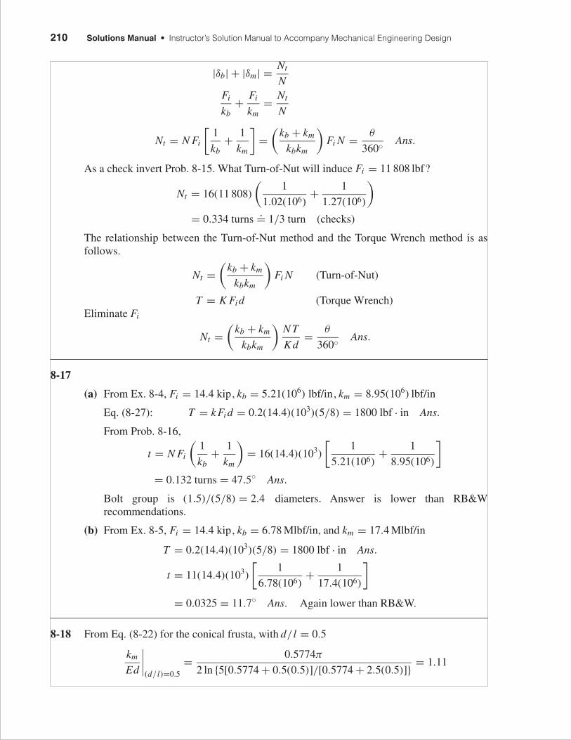
FIRST PAGES
210 Solutions Manual • Instructor’s Solution Manual to Accompany Mechanical Engineering Design
|δb| + |δm| = Nt
NFi
kb+ Fi
km= Nt
N
Nt = N Fi
[1
kb+ 1
km
]=
(kb + km
kbkm
)Fi N = θ
360◦ Ans.
As a check invert Prob. 8-15. What Turn-of-Nut will induce Fi = 11 808 lbf?
Nt = 16(11 808)
(1
1.02(106)+ 1
1.27(106)
)
= 0.334 turns.= 1/3 turn (checks)
The relationship between the Turn-of-Nut method and the Torque Wrench method is asfollows.
Nt =(
kb + km
kbkm
)Fi N (Turn-of-Nut)
T = K Fi d (Torque Wrench)Eliminate Fi
Nt =(
kb + km
kbkm
)N T
K d= θ
360◦ Ans.
8-17
(a) From Ex. 8-4, Fi = 14.4 kip, kb = 5.21(106) lbf/in, km = 8.95(106) lbf/in
Eq. (8-27): T = k Fi d = 0.2(14.4)(103)(5/8) = 1800 lbf · in Ans.
From Prob. 8-16,
t = N Fi
(1
kb+ 1
km
)= 16(14.4)(103)
[1
5.21(106)+ 1
8.95(106)
]
= 0.132 turns = 47.5◦ Ans.
Bolt group is (1.5)/(5/8) = 2.4 diameters. Answer is lower than RB&Wrecommendations.
(b) From Ex. 8-5, Fi = 14.4 kip, kb = 6.78 Mlbf/in, and km = 17.4 Mlbf/in
T = 0.2(14.4)(103)(5/8) = 1800 lbf · in Ans.
t = 11(14.4)(103)
[1
6.78(106)+ 1
17.4(106)
]
= 0.0325 = 11.7◦ Ans. Again lower than RB&W.
8-18 From Eq. (8-22) for the conical frusta, with d/ l = 0.5
km
Ed
∣∣∣∣(d/ l)=0.5
= 0.5774π
2 ln {5[0.5774 + 0.5(0.5)]/[0.5774 + 2.5(0.5)]} = 1.11
budynas_SM_ch08.qxd 11/30/2006 15:49 Page 210

FIRST PAGES
Chapter 8 211
Eq. (8-23), from the Wileman et al. finite element study, using the general expression,
km
Ed
∣∣∣∣(d/ l)=0.5
= 0.789 52 exp[0.629 14(0.5)] = 1.08
8-19 For cast iron, from Table 8-8: A = 0.778 71, B = 0.616 16, E = 14.5 Mpsi
km = 14.5(106)(0.625)(0.778 71) exp
(0.616 16
0.625
1.5
)= 9.12(106) lbf/in
This member’s spring rate applies to both members. We need km for the upper memberwhich represents half of the joint.
kci = 2km = 2[9.12(106)] = 18.24(106) lbf/in
For steel from Table 8-8: A = 0.787 15, B = 0.628 73, E = 30 Mpsi
km = 30(106)(0.625)(0.787 15) exp
(0.628 73
0.625
1.5
)= 19.18(106) lbf/in
ksteel = 2km = 2(19.18)(106) = 38.36(106) lbf/in
For springs in series
1
km= 1
kci+ 1
ksteel= 1
18.24(106)+ 1
38.36(106)
km = 12.4(106) lbf/in Ans.
8-20 The external tensile load per bolt is
P = 1
10
(π
4
)(150)2(6)(10−3) = 10.6 kN
Also, l = 40 mm and from Table A-31, for d = 12 mm, H = 10.8 mm. No washer isspecified.
LT = 2D + 6 = 2(12) + 6 = 30 mm
l + H = 40 + 10.8 = 50.8 mm
Table A-17: L = 60 mm
ld = 60 − 30 = 30 mm
lt = 45 − 30 = 15 mm
Ad = π(12)2
4= 113 mm2
Table 8-1: At = 84.3 mm2
Eq. (8-17):
kb = 113(84.3)(207)
113(15) + 84.3(30)= 466.8 MN/m
Steel: Using Eq. (8-23) for A = 0.787 15, B = 0.628 73 and E = 207 GPa
budynas_SM_ch08.qxd 11/30/2006 15:49 Page 211

FIRST PAGES
212 Solutions Manual • Instructor’s Solution Manual to Accompany Mechanical Engineering Design
Eq. (8-23): km = 207(12)(0.787 15) exp[(0.628 73)(12/40)] = 2361 MN/m
ks = 2km = 4722 MN/m
Cast iron: A = 0.778 71, B = 0.616 16, E = 100 GPa
km = 100(12)(0.778 71) exp[(0.616 16)(12/40)] = 1124 MN/m
kci = 2km = 2248 MN/m
1
km= 1
ks+ 1
kci⇒ km = 1523 MN/m
C = 466.8
466.8 + 1523= 0.2346
Table 8-1: At = 84.3 mm2 , Table 8-11, Sp = 600 MPa
Eqs. (8-30) and (8-31): Fi = 0.75(84.3)(600)(10−3) = 37.9 kN
Eq. (8-28):
n = Sp At − Fi
C P= 600(10−3)(84.3) − 37.9
0.2346(10.6)= 5.1 Ans.
8-21 Computer programs will vary.
8-22 D3 = 150 mm, A = 100 mm, B = 200 mm, C = 300 mm, D = 20 mm, E = 25 mm.ISO 8.8 bolts: d = 12 mm, p = 1.75 mm, coarse pitch of p = 6 MPa.
P = 1
10
(π
4
)(1502)(6)(10−3) = 10.6 kN/bolt
l = D + E = 20 + 25 = 45 mm
LT = 2D + 6 = 2(12) + 6 = 30 mm
Table A-31: H = 10.8 mm
l + H = 45 + 10.8 = 55.8 mmTable A-17: L = 60 mm
ld = 60 − 30 = 30 mm, lt = 45 − 30 = 15 mm, Ad = π(122/4) = 113 mm2
Table 8-1: At = 84.3 mm2
2.5
dw
D1
22.5 25
45
20
budynas_SM_ch08.qxd 11/30/2006 15:49 Page 212

FIRST PAGES
Chapter 8 213
Eq. (8-17):
kb = 113(84.3)(207)
113(15) + 84.3(30)= 466.8 MN/m
There are three frusta: dm = 1.5(12) = 18 mm
D1 = (20 tan 30◦)2 + dw = (20 tan 30◦)2 + 18 = 41.09 mm
Upper Frustum: t = 20 mm, E = 207 GPa, D = 1.5(12) = 18 mm
Eq. (8-20): k1 = 4470 MN/m
Central Frustum: t = 2.5 mm, D = 41.09 mm, E = 100 GPa (Table A-5) ⇒ k2 =52 230 MN/mLower Frustum: t = 22.5 mm, E = 100 GPa, D = 18 mm ⇒ k3 = 2074 MN/m
From Eq. (8-18): km = [(1/4470) + (1/52 230) + (1/2074)]−1 = 1379 MN/m
Eq. (e), p. 421: C = 466.8
466.8 + 1379= 0.253
Eqs. (8-30) and (8-31):
Fi = K Fp = K At Sp = 0.75(84.3)(600)(10−3) = 37.9 kN
Eq. (8-28): n = Sp At − Fi
C P= 600(10−3)(84.3) − 37.9
0.253(10.6)= 4.73 Ans.
8-23 P = 1
8
(π
4
)(1202)(6)(10−3) = 8.48 kN
From Fig. 8-21, t1 = h = 20 mm and t2 = 25 mm
l = 20 + 12/2 = 26 mm
t = 0 (no washer), LT = 2(12) + 6 = 30 mm
L > h + 1.5d = 20 + 1.5(12) = 38 mm
Use 40 mm cap screws.
ld = 40 − 30 = 10 mm
lt = l − ld = 26 − 10 = 16 mm
Ad = 113 mm2, At = 84.3 mm2
Eq. (8-17):
kb = 113(84.3)(207)
113(16) + 84.3(10)
= 744 MN/m Ans.
dw = 1.5(12) = 18 mm
D = 18 + 2(6)(tan 30) = 24.9 mm
l � 26
t2 � 25
h � 20
13
137
6
D
12
budynas_SM_ch08.qxd 11/30/2006 15:49 Page 213

FIRST PAGES
214 Solutions Manual • Instructor’s Solution Manual to Accompany Mechanical Engineering Design
From Eq. (8-20):
Top frustum: D = 18, t = 13, E = 207 GPa ⇒ k1 = 5316 MN/m
Mid-frustum: t = 7, E = 207 GPa, D = 24.9 mm ⇒ k2 = 15 620 MN/m
Bottom frustum: D = 18, t = 6, E = 100 GPa ⇒ k3 = 3887 MN/m
km = 1
(1/5316) + (1/55 620) + (1/3887)= 2158 MN/m Ans.
C = 744
744 + 2158= 0.256 Ans.
From Prob. 8-22, Fi = 37.9 kN
n = Sp At − Fi
C P= 600(0.0843) − 37.9
0.256(8.48)= 5.84 Ans.
8-24 Calculation of bolt stiffness:
H = 7/16 in
LT = 2(1/2) + 1/4 = 1 1/4 in
l = 1/2 + 5/8 + 0.095 = 1.22 in
L > 1.125 + 7/16 + 0.095 = 1.66 in
Use L = 1.75 in
ld = L − LT = 1.75 − 1.25 = 0.500 in
lt = 1.125 + 0.095 − 0.500 = 0.72 in
Ad = π(0.502)/4 = 0.1963 in2
At = 0.1419 in2 (UNC)
kt = At E
lt= 0.1419(30)
0.72= 5.9125 Mlbf/in
kd = Ad E
ld= 0.1963(30)
0.500= 11.778 Mlbf/in
kb = 1
(1/5.9125) + (1/11.778)= 3.936 Mlbf/in Ans.
58
12
0.095
34
1.454
1.327
34
0.860
1.22
0.61
budynas_SM_ch08.qxd 11/30/2006 15:49 Page 214

FIRST PAGES
Chapter 8 215
Member stiffness for four frusta and joint constant C using Eqs. (8-20) and (e).
Top frustum: D = 0.75, t = 0.5, d = 0.5, E = 30 ⇒ k1 = 33.30 Mlbf/in
2nd frustum: D = 1.327, t = 0.11, d = 0.5, E = 14.5 ⇒ k2 = 173.8 Mlbf/in
3rd frustum: D = 0.860, t = 0.515, E = 14.5 ⇒ k3 = 21.47 Mlbf/in
Fourth frustum: D = 0.75, t = 0.095, d = 0.5, E = 30 ⇒ k4 = 97.27 Mlbf/in
km =(
4∑i=1
1/ki
)−1
= 10.79 Mlbf/in Ans.
C = 3.94/(3.94 + 10.79) = 0.267 Ans.
8-25
kb = At E
l= 0.1419(30)
0.845= 5.04 Mlbf/in Ans.
From Fig. 8-21,
h = 1
2+ 0.095 = 0.595 in
l = h + d
2= 0.595 + 0.5
2= 0.845
D1 = 0.75 + 0.845 tan 30◦ = 1.238 in
l/2 = 0.845/2 = 0.4225 in
From Eq. (8-20):Frustum 1: D = 0.75, t = 0.4225 in, d = 0.5 in, E = 30 Mpsi ⇒ k1 = 36.14 Mlbf/in
Frustum 2: D = 1.018 in, t = 0.1725 in, E = 70 Mpsi, d = 0.5 in ⇒ k2 = 134.6 Mlbf/in
Frustum 3: D = 0.75, t = 0.25 in, d = 0.5 in, E = 14.5 Mpsi ⇒ k3 = 23.49 Mlbf/in
km = 1
(1/36.14) + (1/134.6) + (1/23.49)= 12.87 Mlbf/in Ans.
C = 5.04
5.04 + 12.87= 0.281 Ans.
0.095"
0.1725"
0.25"
0.595"0.5"
0.625"
0.4225"
0.845"
0.75"
1.018"
1.238"
Steel
Castiron
budynas_SM_ch08.qxd 11/30/2006 15:49 Page 215

FIRST PAGES
216 Solutions Manual • Instructor’s Solution Manual to Accompany Mechanical Engineering Design
8-26 Refer to Prob. 8-24 and its solution.Additional information: A = 3.5 in, Ds = 4.25 in, staticpressure 1500 psi, Db = 6 in, C (joint constant) = 0.267, ten SAE grade 5 bolts.
P = 1
10
π(4.252)
4(1500) = 2128 lbf
From Tables 8-2 and 8-9,
At = 0.1419 in2
Sp = 85 000 psi
Fi = 0.75(0.1419)(85) = 9.046 kipFrom Eq. (8-28),
n = Sp At − Fi
C P= 85(0.1419) − 9.046
0.267(2.128)= 5.31 Ans.
8-27 From Fig. 8-21, t1 = 0.25 in
h = 0.25 + 0.065 = 0.315 in
l = h + (d/2) = 0.315 + (3/16) = 0.5025 in
D1 = 1.5(0.375) + 0.577(0.5025) = 0.8524 in
D2 = 1.5(0.375) = 0.5625 in
l/2 = 0.5025/2 = 0.251 25 in
Frustum 1: Washer
E = 30 Mpsi, t = 0.065 in, D = 0.5625 ink = 78.57 Mlbf/in (by computer)
Frustum 2: Cap portion
E = 14 Mpsi, t = 0.186 25 in
D = 0.5625 + 2(0.065)(0.577) = 0.6375 in
k = 23.46 Mlbf/in (by computer)
Frustum 3: Frame and Cap
E = 14 Mpsi, t = 0.251 25 in, D = 0.5625 in
k = 14.31 Mlbf/in (by computer)
km = 1
(1/78.57) + (1/23.46) + (1/14.31)= 7.99 Mlbf/in Ans.
0.8524"
0.5625"
0.25125"
0.8524"
0.6375"
0.18625"
0.5625"
0.6375" 0.065"
budynas_SM_ch08.qxd 11/30/2006 15:49 Page 216

FIRST PAGES
Chapter 8 217
For the bolt, LT = 2(3/8) + (1/4) = 1 in. So the bolt is threaded all the way. SinceAt = 0.0775 in2
kb = 0.0775(30)
0.5025= 4.63 Mlbf/in Ans.
8-28
(a) F ′b = RF ′
b,max sin θ
Half of the external moment is contributed by the line load in the interval 0 ≤ θ ≤ π.
M
2=
∫ π
0F ′
b R2 sin θ dθ =∫ π
0F ′
b, max R2 sin2 θ dθ
M
2= π
2F ′
b, max R2
from which F ′b,max = M
π R2
Fmax =∫ φ2
φ1
F ′b R sin θ dθ = M
π R2
∫ φ2
φ1
R sin θ dθ = M
π R(cos φ1 − cos φ2)
Noting φ1 = 75◦ , φ2 = 105◦
Fmax = 12 000
π(8/2)(cos 75◦ − cos 105◦) = 494 lbf Ans.
(b) Fmax = F ′b, max Rφ = M
π R2(R)
(2π
N
)= 2M
RN
Fmax = 2(12 000)
(8/2)(12)= 500 lbf Ans.
(c) F = Fmax sin θ
M = 2Fmax R[(1) sin2 90◦ + 2 sin2 60◦ + 2 sin2 30◦ + (1) sin2(0)] = 6Fmax R
from which
Fmax = M
6R= 12 000
6(8/2)= 500 lbf Ans.
The simple general equation resulted from part (b)
Fmax = 2M
RN
8-29 (a) Table 8-11: Sp = 600 MPa
Eq. (8-30): Fi = 0.9At Sp = 0.9(245)(600)(10−3) = 132.3 kN
Table (8-15): K = 0.18
Eq. (8-27) T = 0.18(132.3)(20) = 476 N · m Ans.
budynas_SM_ch08.qxd 11/30/2006 15:49 Page 217

FIRST PAGES
218 Solutions Manual • Instructor’s Solution Manual to Accompany Mechanical Engineering Design
(b) Washers: t = 3.4 mm, d = 20 mm, D = 30 mm, E = 207 GPa ⇒ k1 = 42 175 MN/m
Cast iron: t = 20 mm, d = 20 mm, D = 30 + 2(3.4) tan 30◦ = 33.93 mm,
E = 135 GPa ⇒ k2 = 7885 MN/m
Steel: t = 20 mm, d = 20 mm, D = 33.93 mm, E = 207 GPa ⇒ k3 = 12 090 MN/m
km = (2/42 175 + 1/7885 + 1/12 090)−1 = 3892 MN/m
Bolt: l = 46.8 mm. Nut: H = 18 mm. L > 46.8 + 18 = 64.8 mm. Use L = 80 mm.
LT = 2(20) + 6 = 46 mm, ld = 80 − 46 = 34 mm, lt = 46.8 − 34 = 12.8 mm,
At = 245 mm2, Ad = π202/4 = 314.2 mm2
kb = Ad At E
Adlt + Atld= 314.2(245)(207)
314.2(12.8) + 245(34)= 1290 MN/m
C = 1290/(1290 + 3892) = 0.2489, Sp = 600 MPa, Fi = 132.3 kN
n = Sp At − Fi
C( P/N )= 600(0.245) − 132.3
0.2489(15/4)= 15.7 Ans.
Bolts are a bit oversized for the load.
8-30 (a) ISO M 20 × 2.5 grade 8.8 coarse pitch bolts, lubricated.
Table 8-2 At = 245 mm2
Table 8-11 Sp = 600 MPa
Ad = π(20)2/4 = 314.2 mm2
Fp = 245(0.600) = 147 kN
Fi = 0.90Fp = 0.90(147) = 132.3 kN
T = 0.18(132.3)(20) = 476 N · m Ans.
(b) L ≥ l + H = 48 + 18 = 66 mm. Therefore, set L = 80 mm per Table A-17.
LT = 2D + 6 = 2(20) + 6 = 46 mm
ld = L − LT = 80 − 46 = 34 mm
lt = l − ld = 48 − 34 = 14 mm
14
Not toscale
80
48 grip
4634
budynas_SM_ch08.qxd 11/30/2006 15:49 Page 218

FIRST PAGES
Chapter 8 219
kb = Ad At E
Adlt + Atld= 314.2(245)(207)
314.2(14) + 245(34)= 1251.9 MN/m
Use Wileman et al.
Eq. (8-23)
A = 0.787 15, B = 0.628 73
km
Ed= A exp
(Bd
LG
)= 0.787 15 exp
[0.628 73
(20
48
)]= 1.0229
km = 1.0229(207)(20) = 4235 MN/m
C = 1251.9
1251.9 + 4235= 0.228
Bolts carry 0.228 of the external load; members carry 0.772 of the external load. Ans.Thus, the actual loads are
Fb = C P + Fi = 0.228(20) + 132.3 = 136.9 kN
Fm = (1 − C) P − Fi = (1 − 0.228)20 − 132.3 = −116.9 kN
8-31 Given pmax = 6 MPa, pmin = 0 and from Prob. 8-20 solution, C = 0.2346, Fi = 37.9 kN,At = 84.3 mm2.
For 6 MPa, P = 10.6 kN per bolt
σi = Fi
At= 37.9(103)
84.3= 450 MPa
Eq. (8-35):
σa = C P
2At= 0.2346(10.6)(103)
2(84.3)= 14.75 MPa
σm = σa + σi = 14.75 + 450 = 464.8 MPa
(a) Goodman Eq. (8-40) for 8.8 bolts with Se = 129 MPa, Sut = 830 MPa
Sa = Se(Sut − σi )
Sut + Se= 129(830 − 450)
830 + 129= 51.12 MPa
n f = Sa
σa= 51.12
14.75= 3.47 Ans.
24
24
30
30
budynas_SM_ch08.qxd 11/30/2006 15:49 Page 219

FIRST PAGES
220 Solutions Manual • Instructor’s Solution Manual to Accompany Mechanical Engineering Design
(b) Gerber Eq. (8-42)
Sa = 1
2Se
[Sut
√S2
ut + 4Se(Se + σi ) − S2ut − 2σi Se
]
= 1
2(129)
[830
√8302 + 4(129)(129 + 450) − 8302 − 2(450)(129)
]
= 76.99 MPa
n f = 76.99
14.75= 5.22 Ans.
(c) ASME-elliptic Eq. (8-43) with Sp = 600 MPa
Sa = Se
S2p + S2
e
(Sp
√S2
p + S2e − σ 2
i − σi Se
)
= 129
6002 + 1292
[600
√6002 + 1292 − 4502 − 450(129)
] = 65.87 MPa
n f = 65.87
14.75= 4.47 Ans.
8-32
P = p A
N= π D2 p
4N= π(0.92)(550)
4(36)= 9.72 kN/bolt
Table 8-11: Sp = 830 MPa, Sut = 1040 MPa, Sy = 940 MPa
Table 8-1: At = 58 mm2
Ad = π(102)/4 = 78.5 mm2
l = D + E = 20 + 25 = 45 mmLT = 2(10) + 6 = 26 mm
Table A-31: H = 8.4 mm
L ≥ l + H = 45 + 8.4 = 53.4 mm
Choose L = 60 mm from Table A-17
ld = L − LT = 60 − 26 = 34 mm
lt = l − ld = 45 − 34 = 11 mm
kb = Ad At E
Adlt + Atld= 78.5(58)(207)
78.5(11) + 58(34)= 332.4 MN/m
2.5
22.5
22.5
25
20
15
10
budynas_SM_ch08.qxd 11/30/2006 15:49 Page 220

FIRST PAGES
Chapter 8 221
Frustum 1: Top, E = 207, t = 20 mm, d = 10 mm, D = 15 mm
k1 = 0.5774π(207)(10)
ln
{[1.155(20) + 15 − 10
1.155(20) + 15 + 10
](15 + 10
15 − 10
)}
= 3503 MN/m
Frustum 2: Middle, E = 96 GPa, D = 38.09 mm, t = 2.5 mm, d = 10 mm
k2 = 0.5774π(96)(10)
ln
{[1.155(2.5) + 38.09 − 10
1.155(2.5) + 38.09 + 10
](38.09 + 10
38.09 − 10
)}
= 44 044 MN/m
could be neglected due to its small influence on km .
Frustum 3: Bottom, E = 96 GPa, t = 22.5 mm, d = 10 mm, D = 15 mm
k3 = 0.5774π(96)(10)
ln
{[1.155(22.5) + 15 − 10
1.155(22.5) + 15 + 10
](15 + 10
15 − 10
)}
= 1567 MN/m
km = 1
(1/3503) + (1/44 044) + (1/1567)= 1057 MN/m
C = 332.4
332.4 + 1057= 0.239
Fi = 0.75At Sp = 0.75(58)(830)(10−3) = 36.1 kN
Table 8-17: Se = 162 MPa
σi = Fi
At= 36.1(103)
58= 622 MPa
(a) Goodman Eq. (8-40)
Sa = Se(Sut − σi )
Sut + Se= 162(1040 − 622)
1040 + 162= 56.34 MPa
n f = 56.34
20= 2.82 Ans.
(b) Gerber Eq. (8-42)
Sa = 1
2Se
[Sut
√S2
ut + 4Se(Se + σi ) − S2ut − 2σi Se
]
= 1
2(162)
[1040
√10402 + 4(162)(162 + 622) − 10402 − 2(622)(162)
]
= 86.8 MPa
budynas_SM_ch08.qxd 11/30/2006 15:49 Page 221

FIRST PAGES
222 Solutions Manual • Instructor’s Solution Manual to Accompany Mechanical Engineering Design
σa = C P
2At= 0.239(9.72)(103)
2(58)= 20 MPa
n f = Sa
σa= 86.8
20= 4.34 Ans.
(c) ASME elliptic
Sa = Se
S2p + S2
e
(Sp
√S2
p + S2e − σ 2
i − σi Se
)
= 162
8302 + 1622
[830
√8302 + 1622 − 6222 − 622(162)
] = 84.90 MPa
n f = 84.90
20= 4.24 Ans.
8-33 Let the repeatedly-applied load be designated as P. From Table A-22, Sut =93.7 kpsi. Referring to the Figure of Prob. 3-74, the following notation will be used for theradii of Section AA.
ri = 1 in, ro = 2 in, rc = 1.5 in
From Table 4-5, with R = 0.5 in
rn = 0.52
2(
1.5 − √1.52 − 0.52
) = 1.457 107 in
e = rc − rn = 1.5 − 1.457 107 = 0.042 893 in
co = ro − rn = 2 − 1.457 109 = 0.542 893 in
ci = rn − ri = 1.457 107 − 1 = 0.457 107 in
A = π(12)/4 = 0.7854 in2
If P is the maximum load
M = Prc = 1.5P
σi = P
A
(1 + rcci
eri
)= P
0.7854
(1 + 1.5(0.457)
0.0429(1)
)= 21.62P
σa = σm = σi
2= 21.62P
2= 10.81P
(a) Eye: Section AA
ka = 14.4(93.7)−0.718 = 0.553
de = 0.37d = 0.37(1) = 0.37 in
kb =(
0.37
0.30
)−0.107
= 0.978
kc = 0.85
S′e = 0.5(93.7) = 46.85 kpsi
Se = 0.553(0.978)(0.85)(46.85) = 21.5 kpsi
budynas_SM_ch08.qxd 11/30/2006 15:49 Page 222

FIRST PAGES
Chapter 8 223
Since no stress concentration exists, use a load line slope of 1. From Table 7-10 forGerber
Sa = 93.72
2(21.5)
⎡⎣−1 +
√1 +
(2(21.5)
93.7
)2⎤⎦ = 20.47 kpsi
Note the mere 5 percent degrading of Se in Sa
n f = Sa
σa= 20.47(103)
10.81P= 1894
P
Thread: Die cut. Table 8-17 gives 18.6 kpsi for rolled threads. Use Table 8-16 to findSe for die cut threads
Se = 18.6(3.0/3.8) = 14.7 kpsiTable 8-2:
At = 0.663 in2
σ = P/At = P/0.663 = 1.51P
σa = σm = σ/2 = 1.51P/2 = 0.755P
From Table 7-10, Gerber
Sa = 1202
2(14.7)
⎡⎣−1 +
√1 +
(2(14.7)
120
)2⎤⎦ = 14.5 kpsi
n f = Sa
σa= 14 500
0.755P= 19 200
P
Comparing 1894/P with 19 200/P, we conclude that the eye is weaker in fatigue.Ans.
(b) Strengthening steps can include heat treatment, cold forming, cross section change (around is a poor cross section for a curved bar in bending because the bulk of the mate-rial is located where the stress is small). Ans.
(c) For n f = 2
P = 1894
2= 947 lbf, max. load Ans.
8-34 (a) L ≥ 1.5 + 2(0.134) + 41
64= 2.41 in. Use L = 21
2 in Ans.
(b) Four frusta: Two washers and two members
1.125"
D1
0.134"
1.280"
0.75"
budynas_SM_ch08.qxd 11/30/2006 15:49 Page 223

FIRST PAGES
224 Solutions Manual • Instructor’s Solution Manual to Accompany Mechanical Engineering Design
Washer: E = 30 Mpsi, t = 0.134 in, D = 1.125 in, d = 0.75 in
Eq. (8-20): k1 = 153.3 Mlbf/in
Member: E = 16 Mpsi, t = 0.75 in, D = 1.280 in, d = 0.75 in
Eq. (8-20): k2 = 35.5 Mlbf/in
km = 1
(2/153.3) + (2/35.5)= 14.41 Mlbf/in Ans.
Bolt:
LT = 2(3/4) + 1/4 = 13/4 in
l = 2(0.134) + 2(0.75) = 1.768 in
ld = L − LT = 2.50 − 1.75 = 0.75 in
lt = l − ld = 1.768 − 0.75 = 1.018 in
At = 0.373 in2 (Table 8-2)
Ad = π(0.75)2/4 = 0.442 in2
kb = Ad At E
Adlt + Atld= 0.442(0.373)(30)
0.442(1.018) + 0.373(0.75)= 6.78 Mlbf/in Ans.
C = 6.78
6.78 + 14.41= 0.320 Ans.
(c) From Eq. (8-40), Goodman with Se = 18.6 kpsi, Sut = 120 kpsi
Sa = 18.6[120 − (25/0.373)]
120 + 18.6= 7.11 kpsi
The stress components are
σa = C P
2At= 0.320(6)
2(0.373)= 2.574 kpsi
σm = σa + Fi
At= 2.574 + 25
0.373= 69.6 kpsi
n f = Sa
σa= 7.11
2.574= 2.76 Ans.
(d) Eq. (8-42) for Gerber
Sa = 1
2(18.6)
[120
√1202 + 4(18.6)
(18.6 + 25
0.373
)− 1202 − 2
(25
0.373
)18.6
]
= 10.78 kpsi
n f = 10.78
2.574= 4.19 Ans.
(e) nproof = 85
2.654 + 69.8= 1.17 Ans.
budynas_SM_ch08.qxd 11/30/2006 15:49 Page 224

FIRST PAGES
Chapter 8 225
8-35
(a) Table 8-2: At = 0.1419 in2
Table 8-9: Sp = 85 kpsi, Sut = 120 kpsi
Table 8-17: Se = 18.6 kpsi
Fi = 0.75At Sp = 0.75(0.1419)(85) = 9.046 kip
C = 4.94
4.94 + 15.97= 0.236
σa = C P
2At= 0.236P
2(0.1419)= 0.832P kpsi
Eq. (8-40) for Goodman criterion
Sa = 18.6(120 − 9.046/0.1419)
120 + 18.6= 7.55 kpsi
n f = Sa
σa= 7.55
0.832P= 2 ⇒ P = 4.54 kip Ans.
(b) Eq. (8-42) for Gerber criterion
Sa = 1
2(18.6)
[120
√1202 + 4(18.6)
(18.6 + 9.046
0.1419
)− 1202 − 2
(9.046
0.1419
)18.6
]
= 11.32 kpsi
n f = Sa
σa= 11.32
0.832P= 2
From which
P = 11.32
2(0.832)= 6.80 kip Ans.
(c) σa = 0.832P = 0.832(6.80) = 5.66 kpsi
σm = Sa + σa = 11.32 + 63.75 = 75.07 kpsi
Load factor, Eq. (8-28)
n = Sp At − Fi
C P= 85(0.1419) − 9.046
0.236(6.80)= 1.88 Ans.
Separation load factor, Eq. (8-29)
n = Fi
(1 − C) P= 9.046
6.80(1 − 0.236)= 1.74 Ans.
8-36 Table 8-2: At = 0.969 in2 (coarse)
At = 1.073 in2 (fine)
Table 8-9: Sp = 74 kpsi, Sut = 105 kpsi
Table 8-17: Se = 16.3 kpsi
budynas_SM_ch08.qxd 11/30/2006 15:49 Page 225

FIRST PAGES
226 Solutions Manual • Instructor’s Solution Manual to Accompany Mechanical Engineering Design
Coarse thread, UNC
Fi = 0.75(0.969)(74) = 53.78 kip
σi = Fi
At= 53.78
0.969= 55.5 kpsi
σa = C P
2At= 0.30P
2(0.969)= 0.155P kpsi
Eq. (8-42):
Sa = 1
2(16.3)
[105
√1052 + 4(16.3)(16.3 + 55.5) − 1052 − 2(55.5)(16.3)
] = 9.96 kpsi
n f = Sa
σa= 9.96
0.155P= 2
From which
P = 9.96
0.155(2)= 32.13 kip Ans.
Fine thread, UNF
Fi = 0.75(1.073)(74) = 59.55 kip
σi = 59.55
1.073= 55.5 kpsi
σa = 0.32P
2(1.073)= 0.149P kpsi
Sa = 9.96 (as before)
n f = Sa
σa= 9.96
0.149P= 2
From which
P = 9.96
0.149(2)= 33.42 kip Ans.
Percent improvement
33.42 − 32.13
32.13(100)
.= 4% Ans.
8-37 For a M 30 × 3.5 ISO 8.8 bolt with P = 80 kN/bolt and C = 0.33
Table 8-1: At = 561 mm2
Table 8-11: Sp = 600 MPa
Sut = 830 MPa
Table 8-17: Se = 129 MPa
budynas_SM_ch08.qxd 11/30/2006 15:49 Page 226

FIRST PAGES
Chapter 8 227
Fi = 0.75(561)(10−3)(600) = 252.45 kN
σi = 252.45(10−3)
561= 450 MPa
σa = C P
2At= 0.33(80)(103)
2(561)= 23.53 MPa
Eq. (8-42):
Sa = 1
2(129)
[830
√8302 + 4(129)(129 + 450) − 8302 − 2(450)(129)
] = 77.0 MPa
Fatigue factor of safety
n f = Sa
σa= 77.0
23.53= 3.27 Ans.
Load factor from Eq. (8-28),
n = Sp At − Fi
C P= 600(10−3)(561) − 252.45
0.33(80)= 3.19 Ans.
Separation load factor from Eq. (8-29),
n = Fi
(1 − C) P= 252.45
(1 − 0.33)(80)= 4.71 Ans.
8-38
(a) Table 8-2: At = 0.0775 in2
Table 8-9: Sp = 85 kpsi, Sut = 120 kpsi
Table 8-17: Se = 18.6 kpsi
Unthreaded grip
kb = Ad E
l= π(0.375)2(30)
4(13.5)= 0.245 Mlbf/in per bolt Ans.
Am = π
4[(D + 2t)2 − D2] = π
4(4.752 − 42) = 5.154 in2
km = Am E
l= 5.154(30)
12
(1
6
)= 2.148 Mlbf/in/bolt. Ans.
(b) Fi = 0.75(0.0775)(85) = 4.94 kip
σi = 0.75(85) = 63.75 kpsi
P = p A = 2000
6
[π
4(4)2
]= 4189 lbf/bolt
C = 0.245
0.245 + 2.148= 0.102
σa = C P
2At= 0.102(4.189)
2(0.0775)= 2.77 kpsi
budynas_SM_ch08.qxd 11/30/2006 15:49 Page 227

FIRST PAGES
228 Solutions Manual • Instructor’s Solution Manual to Accompany Mechanical Engineering Design
Eq. (8-40) for Goodman
Sa = 18.6(120 − 63.75)
120 + 18.6= 7.55 kpsi
n f = Sa
σa= 7.55
2.77= 2.73 Ans.
(c) From Eq. (8-42) for Gerber fatigue criterion,
Sa = 1
2(18.6)
[120
√1202 + 4(18.6)(18.6 + 63.75) − 1202 − 2(63.75)(18.6)
]
= 11.32 kpsi
n f = Sa
σa= 11.32
2.77= 4.09 Ans.
(d) Pressure causing joint separation from Eq. (8-29)
n = Fi
(1 − C) P= 1
P = Fi
1 − C= 4.94
1 − 0.102= 5.50 kip
p = P
A= 5500
π(42)/46 = 2626 psi Ans.
8-39 This analysis is important should the initial bolt tension fail. Members: Sy = 71 kpsi,Ssy = 0.577(71) = 41.0 kpsi . Bolts: SAE grade 8, Sy = 130 kpsi, Ssy = 0.577(130) =75.01 kpsi
Shear in bolts
As = 2
[π(0.3752)
4
]= 0.221 in2
Fs = As Ssy
n= 0.221(75.01)
3= 5.53 kip
Bearing on boltsAb = 2(0.375)(0.25) = 0.188 in2
Fb = AbSyc
n= 0.188(130)
2= 12.2 kip
Bearing on member
Fb = 0.188(71)
2.5= 5.34 kip
Tension of members
At = (1.25 − 0.375)(0.25) = 0.219 in2
Ft = 0.219(71)
3= 5.18 kip
F = min(5.53, 12.2, 5.34, 5.18) = 5.18 kip Ans.
The tension in the members controls the design.
budynas_SM_ch08.qxd 11/30/2006 15:49 Page 228

FIRST PAGES
Chapter 8 229
8-40 Members: Sy = 32 kpsi
Bolts: Sy = 92 kpsi, Ssy = (0.577)92 = 53.08 kpsi
Shear of bolts
As = 2
[π(0.375)2
4
]= 0.221 in2
τ = Fs
As= 4
0.221= 18.1 kpsi
n = Ssy
τ= 53.08
18.1= 2.93 Ans.
Bearing on bolts
Ab = 2(0.25)(0.375) = 0.188 in2
σb = −4
0.188= −21.3 kpsi
n = Sy
|σb| = 92
|−21.3| = 4.32 Ans.
Bearing on members
n = Syc
|σb| = 32
|−21.3| = 1.50 Ans.
Tension of members
At = (2.375 − 0.75)(1/4) = 0.406 in2
σt = 4
0.406= 9.85 kpsi
n = Sy
At= 32
9.85= 3.25 Ans.
8-41 Members: Sy = 71 kpsi
Bolts: Sy = 92 kpsi, Ssy = 0.577(92) = 53.08 kpsi
Shear of bolts
F = Ssy A/n
Fs = 53.08(2)(π/4)(7/8)2
1.8= 35.46 kip
Bearing on bolts
Fb = 2(7/8)(3/4)(92)
2.2= 54.89 kip
Bearing on members
Fb = 2(7/8)(3/4)(71)
2.4= 38.83 kip
budynas_SM_ch08.qxd 11/30/2006 15:49 Page 229

FIRST PAGES
230 Solutions Manual • Instructor’s Solution Manual to Accompany Mechanical Engineering Design
Tension in members
Ft = (3 − 0.875)(3/4)(71)
2.6= 43.52 kip
F = min(35.46, 54.89, 38.83, 43.52) = 35.46 kip Ans.
8-42 Members: Sy = 47 kpsi
Bolts: Sy = 92 kpsi, Ssy = 0.577(92) = 53.08 kpsi
Shear of bolts
Ad = π(0.75)2
4= 0.442 in2
τs = 20
3(0.442)= 15.08 kpsi
n = Ssy
τs= 53.08
15.08= 3.52 Ans.
Bearing on bolt
σb = − 20
3(3/4)(5/8)= −14.22 kpsi
n = − Sy
σb= −
(92
−14.22
)= 6.47 Ans.
Bearing on members
σb = − F
Ab= − 20
3(3/4)(5/8)= −14.22 kpsi
n = − Sy
σb= − 47
14.22= 3.31 Ans.
Tension on members
σt = F
A= 20
(5/8)[7.5 − 3(3/4)]= 6.10 kpsi
n = Sy
σt= 47
6.10= 7.71 Ans.
8-43 Members: Sy = 57 kpsiBolts: Sy = 92 kpsi, Ssy = 0.577(92) = 53.08 kpsi
Shear of bolts
As = 3
[π(3/8)2
4
]= 0.3313 in2
τs = F
A= 5.4
0.3313= 16.3 kpsi
n = Ssy
τs= 53.08
16.3= 3.26 Ans.
budynas_SM_ch08.qxd 11/30/2006 15:49 Page 230

FIRST PAGES
Chapter 8 231
Bearing on bolt
Ab = 3
(3
8
)(5
16
)= 0.3516 in2
σb = − F
Ab= − 5.4
0.3516= −15.36 kpsi
n = − Sy
σb= −
(92
−15.36
)= 5.99 Ans.
Bearing on members
Ab = 0.3516 in2 (From bearing on bolt calculations)
σb = −15.36 kpsi (From bearing on bolt calculations)
n = − Sy
σb= −
(57
−15.36
)= 3.71 Ans.
Tension in membersFailure across two bolts
A = 5
16
[2
3
8− 2
(3
8
)]= 0.5078 in2
σ = F
A= 5.4
0.5078= 10.63 kpsi
n = Sy
σt= 57
10.63= 5.36 Ans.
8-44
By symmetry, R1 = R2 = 1.4 kN
∑MB = 0 1.4(250) − 50RA = 0 ⇒ RA = 7 kN∑MA = 0 200(1.4) − 50RB = 0 ⇒ RB = 5.6 kN
Members: Sy = 370 MPa
Bolts: Sy = 420 MPa, Ssy = 0.577(420) = 242.3 MPa
Bolt shear: As = π
4(102) = 78.54 mm2
τ = 7(103)
78.54= 89.13 MPa
n = Ssy
τ= 242.3
89.13= 2.72
A B
1.4 kN
200 50
RB
RA
C
R1
350 350
R2
2.8 kN
budynas_SM_ch08.qxd 11/30/2006 15:49 Page 231

FIRST PAGES
232 Solutions Manual • Instructor’s Solution Manual to Accompany Mechanical Engineering Design
Bearing on member: Ab = td = 10(10) = 100 mm2
σb = −7(103)
100= −70 MPa
n = − Sy
σ= −370
−70= 5.29
Strength of memberAt A, M = 1.4(200) = 280 N · m
IA = 1
12[10(503) − 10(103)] = 103.3(103) mm4
σA = Mc
IA= 280(25)
103.3(103)(103) = 67.76 MPa
n = Sy
σA= 370
67.76= 5.46
At C, M = 1.4(350) = 490 N · m
IC = 1
12(10)(503) = 104.2(103) mm4
σC = 490(25)
104.2(103)(103) = 117.56 MPa
n = Sy
σC= 370
117.56= 3.15 < 5.46 C more critical
n = min(2.72, 5.29, 3.15) = 2.72 Ans.
8-45
Fs = 3000 lbf
P = 3000(3)
7= 1286 lbf
H = 7
16in
l = 1
2+ 1
2+ 0.095 = 1.095 in
L ≥ l + H = 1.095 + (7/16) = 1.532 in
12"
12"
134
"
l
3000 lbf
Fs
P
O
3"
7" 3"
Pivot aboutthis point
budynas_SM_ch08.qxd 11/30/2006 15:50 Page 232

FIRST PAGES
Chapter 8 233
Use 13
4
"bolts
LT = 2D + 1
4= 2(0.5) + 0.25 = 1.25 in
ld = 1.75 − 1.25 = 0.5
lt = 1.095 − 0.5 = 0.595
Ad = π(0.5)2
4= 0.1963 in2
At = 0.1419 in
kb = Ad At E
Adlt + Atld
= 0.1963(0.1419)(30)
0.1963(0.595) + 0.1419(0.5)
= 4.451 Mlbf/in
Two identical frusta
A = 0.787 15, B = 0.628 73
km = Ed A exp
(0.628 73
d
LG
)
= 30(0.5)(0.787 15)
[exp
(0.628 73
0.5
1.095
)]
km = 15.733 Mlbf/in
C = 4.451
4.451 + 15.733= 0.2205
Sp = 85 kpsi
Fi = 0.75(0.1419)(85) = 9.046 kip
σi = 0.75(85) = 63.75 kpsi
σb = C P + Fi
At= 0.2205(1.286) + 9.046
0.1419= 65.75 kpsi
τs = Fs
As= 3
0.1963= 15.28 kpsi
von Mises stress
σ ′ = (σ 2
b + 3τ 2s
)1/2 = [65.742 + 3(15.282)]1/2 = 70.87 kpsi
Stress margin
m = Sp − σ ′ = 85 − 70.87 = 14.1 kpsi Ans.
0.75"
0.5"
t � 0.5475"
budynas_SM_ch08.qxd 11/30/2006 15:50 Page 233

FIRST PAGES
234 Solutions Manual • Instructor’s Solution Manual to Accompany Mechanical Engineering Design
8-46 2P(200) = 12(50)
P = 12(50)
2(200)= 1.5 kN per bolt
Fs = 6 kN/bolt
Sp = 380 MPa
At = 245 mm2, Ad = π
4(202) = 314.2 mm2
Fi = 0.75(245)(380)(10−3) = 69.83 kN
σi = 69.83(103)
245= 285 MPa
σb = C P + Fi
At=
(0.30(1.5) + 69.83
245
)(103) = 287 MPa
τ = Fs
Ad= 6(103)
314.2= 19.1 MPa
σ ′ = [2872 + 3(19.12)]1/2 = 289 MPa
m = Sp − σ ′ = 380 − 289 = 91 MPa
Thus the bolt will not exceed the proof stress. Ans.
8-47 Using the result of Prob. 5-31 for lubricated assembly
Fx = 2π f T
0.18dWith a design factor of nd gives
T = 0.18nd Fxd
2π f= 0.18(3)(1000)d
2π(0.12)= 716d
or T/d = 716. AlsoT
d= K (0.75Sp At )
= 0.18(0.75)(85 000) At
= 11 475At
Form a table
Size At T/d = 11 475At n
14 � 28 0.0364 417.7 1.75
516 � 24 0.058 665.55 2.8
38 � 24 0.0878 1007.5 4.23
The factor of safety in the last column of the table comes from
n = 2π f (T/d)
0.18Fx= 2π(0.12)(T/d)
0.18(1000)= 0.0042(T/d)
12 kN
2Fs
2P
O
20050
budynas_SM_ch08.qxd 11/30/2006 15:50 Page 234

FIRST PAGES
Chapter 8 235
Select a 38" − 24 UNF capscrew. The setting is given by
T = (11 475At )d = 1007.5(0.375) = 378 lbf · in
Given the coarse scale on a torque wrench, specify a torque wrench setting of 400 lbf · in.Check the factor of safety
n = 2π f T
0.18Fxd= 2π(0.12)(400)
0.18(1000)(0.375)= 4.47
8-48
Bolts: Sp = 380 MPa, Sy = 420 MPaChannel: t = 6.4 mm, Sy = 170 MPaCantilever: Sy = 190 MPaNut: H = 10.8 mm
F ′A = F ′
B = F ′C = F/3
M = (50 + 26 + 125)F = 201F
F ′′A = F ′′
C = 201F
2(50)= 2.01F
FC = F ′C + F ′′
C =(
1
3+ 2.01
)F = 2.343F
Bolts:The shear bolt area is A = π(122)/4 = 113.1 mm2
Ssy = 0.577(420) = 242.3 MPa
F = Ssy
n
(A
2.343
)= 242.3(113.1)(10−3)
2.8(2.343)= 4.18 kN
Bearing on bolt: For a 12-mm bolt, at the channel,
Ab = td = (6.4)(12) = 76.8 mm2
F = Sy
n
(Ab
2.343
)= 420
2.8
[76.8(10−3)
2.343
]= 4.92 kN
Bearing on channel: Ab = 76.8 mm2, Sy = 170 MPa
F = 170
2.8
[76.8(10−3)
2.343
]= 1.99 kN
26
152
B
F'BF'A
A
M
C
F"A
F'C
F"C
50 50
budynas_SM_ch08.qxd 11/30/2006 15:50 Page 235

FIRST PAGES
236 Solutions Manual • Instructor’s Solution Manual to Accompany Mechanical Engineering Design
Bearing on cantilever:
Ab = 12(12) = 144 mm2
F = 190
2.8
[(144)(10−3)
2.343
]= 4.17 kN
Bending of cantilever:
I = 1
12(12)(503 − 123) = 1.233(105) mm4
I
c= 1.233(105)
25= 4932
F = M
151= 4932(190)
2.8(151)(103)= 2.22 kN
So F = 1.99 kN based on bearing on channel Ans.
8-49 F ′ = 4 kN; M = 12(200) = 2400 N · m
F ′′A = F ′′
B = 2400
64= 37.5 kN
FA = FB =√
(4)2 + (37.5)2 = 37.7 kN Ans.
FO = 4 kN Ans.
Bolt shear:
As = π(12)2
4= 113 mm2
τ = 37.7(10)3
113= 334 MPa Ans.
Bearing on member:Ab = 12(8) = 96 mm2
σ = −37.7(10)3
96= −393 MPa Ans.
Bending stress in plate:
I = bh3
12− bd3
12− 2
(bd3
12+ a2bd
)
= 8(136)3
12− 8(12)3
12− 2
[8(12)3
12+ (32)2(8)(12)
]
= 1.48(10)6 mm4 Ans.
M = 12(200) = 2400 N · m
σ = Mc
I= 2400(68)
1.48(10)6(10)3 = 110 MPa Ans.
a
h
a
b
d
F'A � 4 kN
F"A � 37.5 kN
F"B � 37.5 kN
F'O � 4 kN32
32
A
O
B
F'B � 4 kN
budynas_SM_ch08.qxd 11/30/2006 15:50 Page 236

FIRST PAGES
Chapter 8 237
8-50
Bearing on members: Sy = 54 kpsi, n = 54
9.6= 5.63 Ans.
Bending of members: Considering the right-hand bolt
M = 300(15) = 4500 lbf · in
I = 0.375(2)3
12− 0.375(0.5)3
12= 0.246 in4
σ = Mc
I= 4500(1)
0.246= 18 300 psi
n = 54(10)3
18 300= 2.95 Ans.
8-51 The direct shear load per bolt is F ′ = 2500/6 = 417 lbf. The moment is taken only by thefour outside bolts. This moment is M = 2500(5) = 12 500 lbf · in.
Thus F ′′ = 12 500
2(5)= 1250 lbf and the resultant bolt load is
F =√
(417)2 + (1250)2 = 1318 lbf
Bolt strength, Sy = 57 kpsi; Channel strength, Sy = 46 kpsi; Plate strength, Sy = 45.5 kpsi
Shear of bolt: As = π(0.625)2/4 = 0.3068 in2
n = Ssy
τ= (0.577)(57 000)
1318/0.3068= 7.66 Ans.
2"
38"
12"
F ′′A = F ′′
B = 4950
3= 1650 lbf
FA = 1500 lbf, FB = 1800 lbf
Bearing on bolt:
Ab = 1
2
(3
8
)= 0.1875 in2
σ = − F
A= − 1800
0.1875= −9600 psi
n = 92
9.6= 9.58 Ans.
Shear of bolt:
As = π
4(0.5)2 = 0.1963 in2
τ = F
A= 1800
0.1963= 9170 psi
Ssy = 0.577(92) = 53.08 kpsi
n = 53.08
9.17= 5.79 Ans.
F'A � 150 lbf
AB
F'B � 150 lbfy
xO
F"B � 1650 lbfF"A � 1650 lbf
1 12" 1 1
2"
300 lbfM � 16.5(300) � 4950 lbf •in
V � 300 lbf
16 12"
budynas_SM_ch08.qxd 11/30/2006 15:50 Page 237

FIRST PAGES
238 Solutions Manual • Instructor’s Solution Manual to Accompany Mechanical Engineering Design
Bearing on bolt: Channel thickness is t = 3/16 in;
Ab = (0.625)(3/16) = 0.117 in2; n = 57 000
1318/0.117= 5.07 Ans.
Bearing on channel: n = 46 000
1318/0.117= 4.08 Ans.
Bearing on plate: Ab = 0.625(1/4) = 0.1563 in2
n = 45 500
1318/0.1563= 5.40 Ans.
Bending of plate:
I = 0.25(7.5)3
12− 0.25(0.625)3
12
− 2
[0.25(0.625)3
12+
(1
4
)(5
8
)(2.5)2
]= 6.821 in4
M = 6250 lbf · in per plate
σ = Mc
I= 6250(3.75)
6.821= 3436 psi
n = 45 500
3436= 13.2 Ans.
8-52 Specifying bolts, screws, dowels and rivets is the way a student learns about such compo-nents. However, choosing an array a priori is based on experience. Here is a chance forstudents to build some experience.
8-53 Now that the student can put an a priori decision of an array together with the specificationof fasteners.
8-54 A computer program will vary with computer language or software application.
58
D"
14"
127
"5"
budynas_SM_ch08.qxd 11/30/2006 15:50 Page 238

FIRST PAGES
Chapter 9
9-1 Eq. (9-3):
F = 0.707hlτ = 0.707(5/16)(4)(20) = 17.7 kip Ans.
9-2 Table 9-6: τall = 21.0 kpsi
f = 14.85h kip/in
= 14.85(5/16) = 4.64 kip/in
F = f l = 4.64(4) = 18.56 kip Ans.
9-3 Table A-20:
1018 HR: Sut = 58 kpsi, Sy = 32 kpsi
1018 CR: Sut = 64 kpsi, Sy = 54 kpsi
Cold-rolled properties degrade to hot-rolled properties in the neighborhood of the weld.
Table 9-4:
τall = min(0.30Sut , 0.40Sy)
= min[0.30(58), 0.40(32)]
= min(17.4, 12.8) = 12.8 kpsi
for both materials.
Eq. (9-3): F = 0.707hlτall
F = 0.707(5/16)(4)(12.8) = 11.3 kip Ans.
9-4 Eq. (9-3)
τ =√
2F
hl=
√2(32)
(5/16)(4)(2)= 18.1 kpsi Ans.
9-5 b = d = 2 in
(a) Primary shear Table 9-1
τ ′y = V
A= F
1.414(5/16)(2)= 1.13F kpsi
F
7"
1.414
budynas_SM_ch09.qxd 12/01/2006 16:16 Page 239

FIRST PAGES
240 Solutions Manual • Instructor’s Solution Manual to Accompany Mechanical Engineering Design
Secondary shear Table 9-1
Ju = d(3b2 + d2)
6= 2[(3)(22) + 22]
6= 5.333 in3
J = 0.707h Ju = 0.707(5/16)(5.333) = 1.18 in4
τ ′′x = τ ′′
y = Mry
J= 7F(1)
1.18= 5.93F kpsi
Maximum shear
τmax =√
τ ′′2x + (τ ′
y + τ ′′y )2 = F
√5.932 + (1.13 + 5.93)2 = 9.22F kpsi
F = τall
9.22= 20
9.22= 2.17 kip Ans. (1)
(b) For E7010 from Table 9-6, τall = 21 kpsi
Table A-20:
HR 1020 Bar: Sut = 55 kpsi, Sy = 30 kpsi
HR 1015 Support: Sut = 50 kpsi, Sy = 27.5 kpsi
Table 9-5, E7010 Electrode: Sut = 70 kpsi, Sy = 57 kpsi
The support controls the design.
Table 9-4:
τall = min[0.30(50), 0.40(27.5)] = min[15, 11] = 11 kpsi
The allowable load from Eq. (1) is
F = τall
9.22= 11
9.22= 1.19 kip Ans.
9-6 b = d = 2 in
Primary shear
τ ′y = V
A= F
1.414(5/16)(2 + 2)= 0.566F
Secondary shear
Table 9-1: Ju = (b + d)3
6= (2 + 2)3
6= 10.67 in3
J = 0.707h Ju = 0.707(5/16)(10.67) = 2.36 in4
τ ′′x = τ ′′
y = Mry
J= (7F)(1)
2.36= 2.97F
F
7"
budynas_SM_ch09.qxd 12/01/2006 16:16 Page 240

FIRST PAGES
Chapter 9 241
Maximum shear
τmax =√
τ ′′2x + (τ ′
y + τ ′′y )2 = F
√2.972 + (0.556 + 2.97)2 = 4.61F kpsi
F = τall
4.61Ans.
which is twice τmax/9.22 of Prob. 9-5.
9-7 Weldment, subjected to alternating fatigue, has throat area of
A = 0.707(6)(60 + 50 + 60) = 721 mm2
Members’ endurance limit: AISI 1010 steel
Sut = 320 MPa, S′e = 0.5(320) = 160 MPa
ka = 272(320)−0.995 = 0.875
kb = 1 (direct shear)
kc = 0.59 (shear)
kd = 1
k f = 1
K f s= 1
2.7= 0.370
Sse = 0.875(1)(0.59)(0.37)(160) = 30.56 MPa
Electrode’s endurance: 6010
Sut = 62(6.89) = 427 MPa
S′e = 0.5(427) = 213.5 MPa
ka = 272(427)−0.995 = 0.657
kb = 1 (direct shear)
kc = 0.59 (shear)
kd = 1
k f = 1/K f s = 1/2.7 = 0.370
Sse = 0.657(1)(0.59)(0.37)(213.5) = 30.62 MPa.= 30.56
Thus, the members and the electrode are of equal strength. For a factor of safety of 1,
Fa = τa A = 30.6(721)(10−3) = 22.1 kN Ans.
budynas_SM_ch09.qxd 12/01/2006 16:16 Page 241

FIRST PAGES
242 Solutions Manual • Instructor’s Solution Manual to Accompany Mechanical Engineering Design
9-8 Primary shear τ ′ = 0 (why?)
Secondary shear
Table 9-1: Ju = 2πr3 = 2π(4)3 = 402 cm3
J = 0.707h Ju = 0.707(0.5)(402) = 142 cm4
M = 200F N · m (F in kN)
τ ′′ = Mr
2J= (200F)(4)
2(142)= 2.82F (2 welds)
F = τall
τ ′′ = 140
2.82= 49.2 kN Ans.
9-9 Rank
fom′ = Ju
lh= a3/12
ah= a2
12h= 0.0833
(a2
h
)5
fom′ = a(3a2 + a2)
6(2a)h= a2
3h= 0.3333
(a2
h
)1
fom′ = (2a)4 − 6a2a2
12(a + a)2ah= 5a2
24h= 0.2083
(a2
h
)4
fom′ = 1
3ah
[8a3 + 6a3 + a3
12− a4
2a + a
]= 11
36
a2
h= 0.3056
(a2
h
)2
fom′ = (2a)3
6h
1
4a= 8a3
24ah= a2
3h= 0.3333
(a2
h
)1
fom′ = 2π(a/2)3
πah= a3
4ah= a2
4h= 0.25
(a2
h
)3
These rankings apply to fillet weld patterns in torsion that have a square area a × a inwhich to place weld metal. The object is to place as much metal as possible to the border.If your area is rectangular, your goal is the same but the rankings may change.
Students will be surprised that the circular weld bead does not rank first.
9-10
fom′ = Iu
lh= 1
a
(a3
12
)(1
h
)= 1
12
(a2
h
)= 0.0833
(a2
h
)5
fom′ = Iu
lh= 1
2ah
(a3
6
)= 0.0833
(a2
h
)5
fom′ = Iu
lh= 1
2ah
(a2
2
)= 1
4
(a2
h
)= 0.25
(a2
h
)1
budynas_SM_ch09.qxd 12/01/2006 16:16 Page 242

FIRST PAGES
Chapter 9 243
fom′ = Iu
lh= 1
[2(2a)]h
(a2
6
)(3a + a) = 1
6
(a2
h
)= 0.1667
(a2
h
)2
x = b
2= a
2, y = d2
b + 2d= a2
3a= a
3
Iu = 2d3
3− 2d2
(a
3
)+ (b + 2d)
(a2
9
)= 2a3
3− 2a3
3+ 3a
(a2
9
)= a3
3
fom′ = Iu
lh= a3/3
3ah= 1
9
(a2
h
)= 0.1111
(a2
h
)4
Iu = πr3 = πa3
8
fom′ = Iu
lh= πa3/8
πah= a2
8h= 0.125
(a2
h
)3
The CEE-section pattern was not ranked because the deflection of the beam is out-of-plane.
If you have a square area in which to place a fillet weldment pattern under bending, yourobjective is to place as much material as possible away from the x-axis. If your area is rec-tangular, your goal is the same, but the rankings may change.
9-11 Materials:
Attachment (1018 HR) Sy = 32 kpsi, Sut = 58 kpsi
Member (A36) Sy = 36 kpsi, Sut ranges from 58 to 80 kpsi, use 58.
The member and attachment are weak compared to the E60XX electrode.
Decision Specify E6010 electrode
Controlling property: τall = min[0.3(58), 0.4(32)] = min(16.6, 12.8) = 12.8 kpsi
For a static load the parallel and transverse fillets are the same. If n is the number of beads,
τ = F
n(0.707)hl= τall
nh = F
0.707lτall= 25
0.707(3)(12.8)= 0.921
Make a table.
Number of beads Leg sizen h
1 0.9212 0.460 →1/2"3 0.307 →5/16"4 0.230 →1/4"
Decision: Specify 1/4" leg size
Decision: Weld all-around
budynas_SM_ch09.qxd 12/01/2006 16:16 Page 243

FIRST PAGES
244 Solutions Manual • Instructor’s Solution Manual to Accompany Mechanical Engineering Design
Weldment Specifications:
Pattern: All-around squareElectrode: E6010Type: Two parallel fillets Ans.
Two transverse filletsLength of bead: 12 inLeg: 1/4 in
For a figure of merit of, in terms of weldbead volume, is this design optimal?
9-12 Decision: Choose a parallel fillet weldment pattern. By so-doing, we’ve chosen an optimalpattern (see Prob. 9-9) and have thus reduced a synthesis problem to an analysis problem:
Table 9-1: A = 1.414hd = 1.414(h)(3) = 4.24h in3
Primary shear
τ ′y = V
A= 3000
4.24h= 707
hSecondary shear
Table 9-1: Ju = d(3b2 + d2)
6= 3[3(32) + 32]
6= 18 in3
J = 0.707(h)(18) = 12.7h in4
τ ′′x = Mry
J= 3000(7.5)(1.5)
12.7h= 2657
h= τ ′′
y
τmax =√
τ ′′2x + (τ ′
y + τ ′′y )2 = 1
h
√26572 + (707 + 2657)2 = 4287
h
Attachment (1018 HR): Sy = 32 kpsi, Sut = 58 kpsi
Member (A36): Sy = 36 kpsi
The attachment is weaker
Decision: Use E60XX electrode
τall = min[0.3(58), 0.4(32)] = 12.8 kpsi
τmax = τall = 4287
h= 12 800 psi
h = 4287
12 800= 0.335 in
Decision: Specify 3/8" leg size
Weldment Specifications:Pattern: Parallel fillet weldsElectrode: E6010Type: Fillet Ans.Length of bead: 6 inLeg size: 3/8 in
budynas_SM_ch09.qxd 12/01/2006 16:16 Page 244

FIRST PAGES
Chapter 9 245
9-13 An optimal square space (3" × 3") weldment pattern is � � or or �. In Prob. 9-12, therewas roundup of leg size to 3/8 in. Consider the member material to be structural A36 steel.
Decision: Use a parallel horizontal weld bead pattern for welding optimization andconvenience.
Materials:
Attachment (1018 HR): Sy = 32 kpsi, Sut = 58 kpsi
Member (A36): Sy = 36 kpsi, Sut 58–80 kpsi; use 58 kpsi
From Table 9-4 AISC welding code,
τall = min[0.3(58), 0.4(32)] = min(16.6, 12.8) = 12.8 kpsi
Select a stronger electrode material from Table 9-3.
Decision: Specify E6010
Throat area and other properties:
A = 1.414hd = 1.414(h)(3) = 4.24h in2
x = b/2 = 3/2 = 1.5 in
y = d/2 = 3/2 = 1.5 in
Ju = d(3b2 + d2)
6= 3[3(32) + 32]
6= 18 in3
J = 0.707h Ju = 0.707(h)(18) = 12.73h in4
Primary shear:
τ ′x = V
A= 3000
4.24h= 707.5
h
Secondary shear:
τ ′′ = Mr
J
τ ′′x = τ ′′ cos 45◦ = Mr
Jcos 45◦ = Mrx
J
τ ′′x = 3000(6 + 1.5)(1.5)
12.73h= 2651
h
τ ′′y = τ ′′
x = 2651
h
ry
x
rxr ���
���
��
y
x
x
���y
budynas_SM_ch09.qxd 12/01/2006 16:16 Page 245

FIRST PAGES
246 Solutions Manual • Instructor’s Solution Manual to Accompany Mechanical Engineering Design
τmax =√
(τ ′′x + τ ′
x )2 + τ ′′2y
= 1
h
√(2651 + 707.5)2 + 26512
= 4279
hpsi
Relate stress and strength:
τmax = τall
4279
h= 12 800
h = 4279
12 800= 0.334 in → 3/8 in
Weldment Specifications:
Pattern: Horizontal parallel weld tracksElectrode: E6010Type of weld: Two parallel fillet weldsLength of bead: 6 inLeg size: 3/8 in
Additional thoughts:
Since the round-up in leg size was substantial, why not investigate a backward C � weldpattern. One might then expect shorter horizontal weld beads which will have the advan-tage of allowing a shorter member (assuming the member has not yet been designed). Thiswill show the inter-relationship between attachment design and supporting members.
9-14 Materials:
Member (A36): Sy = 36 kpsi, Sut = 58 to 80 kpsi; use Sut = 58 kpsi
Attachment (1018 HR): Sy = 32 kpsi, Sut = 58 kpsi
τall = min[0.3(58), 0.4(32)] = 12.8 kpsi
Decision: Use E6010 electrode. From Table 9-3: Sy = 50 kpsi, Sut = 62 kpsi,τall = min[0.3(62), 0.4(50)] = 20 kpsi
Decision: Since A36 and 1018 HR are weld metals to an unknown extent, useτall = 12.8 kpsi
Decision: Use the most efficient weld pattern–square, weld-all-around. Choose 6" × 6" size.
Attachment length:
l1 = 6 + a = 6 + 6.25 = 12.25 in
Throat area and other properties:
A = 1.414h(b + d) = 1.414(h)(6 + 6) = 17.0h
x = b
2= 6
2= 3 in, y = d
2= 6
2= 3 in
budynas_SM_ch09.qxd 12/01/2006 16:16 Page 246

FIRST PAGES
Chapter 9 247
Primary shear
τ ′y = V
A= F
A= 20 000
17h= 1176
hpsi
Secondary shear
Ju = (b + d)3
6= (6 + 6)3
6= 288 in3
J = 0.707h(288) = 203.6h in4
τ ′′x = τ ′′
y = Mry
J= 20 000(6.25 + 3)(3)
203.6h= 2726
hpsi
τmax =√
τ ′′2x + (τ ′′
y + τ ′y)2 = 1
h
√27262 + (2726 + 1176)2 = 4760
hpsi
Relate stress to strength
τmax = τall
4760
h= 12 800
h = 4760
12 800= 0.372 in
Decision:Specify 3/8 in leg size
Specifications:Pattern: All-around square weld bead trackElectrode: E6010Type of weld: FilletWeld bead length: 24 inLeg size: 3/8 inAttachment length: 12.25 in
9-15 This is a good analysis task to test the students’ understanding
(1) Solicit information related to a priori decisions.(2) Solicit design variables b and d.(3) Find h and round and output all parameters on a single screen. Allow return to Step 1
or Step 2.(4) When the iteration is complete, the final display can be the bulk of your adequacy
assessment.
Such a program can teach too.
9-16 The objective of this design task is to have the students teach themselves that the weldpatterns of Table 9-3 can be added or subtracted to obtain the properties of a comtem-plated weld pattern. The instructor can control the level of complication. I have left the
budynas_SM_ch09.qxd 12/01/2006 16:16 Page 247

FIRST PAGES
248 Solutions Manual • Instructor’s Solution Manual to Accompany Mechanical Engineering Design
presentation of the drawing to you. Here is one possibility. Study the problem’s opportuni-ties, then present this (or your sketch) with the problem assignment.
Use b1 as the design variable. Express properties as a function of b1 . From Table 9-3,category 3:
A = 1.414h(b − b1)
x = b/2, y = d/2
Iu = bd2
2− b1d2
2= (b − b1)d2
2
I = 0.707hIu
τ ′ = V
A= F
1.414h(b − b1)
τ ′′ = Mc
I= Fa(d/2)
0.707hIu
τmax =√
τ ′2 + τ ′′2
Parametric study
Let a = 10 in, b = 8 in, d = 8 in, b1 = 2 in, τall = 12.8 kpsi, l = 2(8 − 2) = 12 in
A = 1.414h(8 − 2) = 8.48h in2
Iu = (8 − 2)(82/2) = 192 in3
I = 0.707(h)(192) = 135.7h in4
τ ′ = 10 000
8.48h= 1179
hpsi
τ ′′ = 10 000(10)(8/2)
135.7h= 2948
hpsi
τmax = 1
h
√11792 + 29482 = 3175
h= 12 800
from which h = 0.248 in. Do not round off the leg size – something to learn.
fom′ = Iu
hl= 192
0.248(12)= 64.5
A = 8.48(0.248) = 2.10 in2
I = 135.7(0.248) = 33.65 in4
Section AA
A36
Body weldsnot shown
8"
8"
12
"
a
A
A
10000 lbf
1018 HR
Attachment weldpattern considered
b
b1
d
budynas_SM_ch09.qxd 12/01/2006 16:16 Page 248

FIRST PAGES
Chapter 9 249
vol = h2
2l = 0.2482
212 = 0.369 in3
I
vol= 33.65
0.369= 91.2 = eff
τ ′ = 1179
0.248= 4754 psi
τ ′′ = 2948
0.248= 11 887 psi
τmax = 4127
0.248.= 12 800 psi
Now consider the case of uninterrupted welds,
b1 = 0
A = 1.414(h)(8 − 0) = 11.31h
Iu = (8 − 0)(82/2) = 256 in3
I = 0.707(256)h = 181h in4
τ ′ = 10 000
11.31h= 884
h
τ ′′ = 10 000(10)(8/2)
181h= 2210
h
τmax = 1
h
√8842 + 22102 = 2380
h= τall
h = τmax
τall= 2380
12 800= 0.186 in
Do not round off h.
A = 11.31(0.186) = 2.10 in2
I = 181(0.186) = 33.67
τ ′ = 884
0.186= 4753 psi, vol = 0.1862
216 = 0.277 in3
τ ′′ = 2210
0.186= 11 882 psi
fom′ = Iu
hl= 256
0.186(16)= 86.0
eff = I
(h2/2)l= 33.67
(0.1862/2)16= 121.7
Conclusions: To meet allowable stress limitations, I and A do not change, nor do τ and σ . Tomeet the shortened bead length, h is increased proportionately. However, volume of bead laiddown increases as h2 . The uninterrupted bead is superior. In this example, we did not round hand as a result we learned something. Our measures of merit are also sensitive to rounding.When the design decision is made, rounding to the next larger standard weld fillet size willdecrease the merit.
budynas_SM_ch09.qxd 12/01/2006 16:16 Page 249

FIRST PAGES
250 Solutions Manual • Instructor’s Solution Manual to Accompany Mechanical Engineering Design
Had the weld bead gone around the corners, the situation would change. Here is a fol-lowup task analyzing an alternative weld pattern.
9-17 From Table 9-2
For the box A = 1.414h(b + d)
Subtracting b1 from b and d1 from d
A = 1.414 h(b − b1 + d − d1)
Iu = d2
6(3b + d) − d3
1
6− b1d2
2
= 1
2(b − b1)d2 + 1
6
(d3 − d3
1
)
length of bead l = 2(b − b1 + d − d1)
fom = Iu/hl
9-18 Computer programs will vary.
9-19 τall = 12 800 psi. Use Fig. 9-17(a) for general geometry, but employ beads and then � �beads.
Horizontal parallel weld bead pattern
b = 6 in
d = 8 in
From Table 9-2, category 3
A = 1.414 hb = 1.414(h)(6) = 8.48 h in2
x = b/2 = 6/2 = 3 in, y = d/2 = 8/2 = 4 in
Iu = bd2
2= 6(8)2
2= 192 in3
I = 0.707hIu = 0.707(h)(192) = 135.7h in4
τ ′ = 10 000
8.48h= 1179
hpsi
6"
8"
b
b1
dd1
budynas_SM_ch09.qxd 12/01/2006 16:16 Page 250

FIRST PAGES
Chapter 9 251
τ ′′ = Mc
I= 10 000(10)(8/2)
135.7h= 2948
hpsi
τmax =√
τ ′2 + τ ′′2 = 1
h(11792 + 29482)1/2 = 3175
hpsi
Equate the maximum and allowable shear stresses.
τmax = τall = 3175
h= 12 800
from which h = 0.248 in. It follows that
I = 135.7(0.248) = 33.65 in4
The volume of the weld metal is
vol = h2l
2= 0.2482(6 + 6)
2= 0.369 in3
The effectiveness, (eff)H , is
(eff)H = I
vol= 33.65
0.369= 91.2 in
(fom′)H = Iu
hl= 192
0.248(6 + 6)= 64.5 in
Vertical parallel weld beads
b = 6 in
d = 8 in
From Table 9-2, category 2
A = 1.414hd = 1.414(h)(8) = 11.31h in2
x = b/2 = 6/2 = 3 in, y = d/2 = 8/2 = 4 in
Iu = d3
6= 83
6= 85.33 in3
I = 0.707hIu = 0.707(h)(85.33) = 60.3h
τ ′ = 10 000
11.31h= 884
hpsi
τ ′′ = Mc
I= 10 000(10)(8/2)
60.3 h= 6633
hpsi
τmax =√
τ ′2 + τ ′′2 = 1
h(8842 + 66332)1/2
= 6692
hpsi
8"
6"
budynas_SM_ch09.qxd 12/01/2006 16:16 Page 251

FIRST PAGES
252 Solutions Manual • Instructor’s Solution Manual to Accompany Mechanical Engineering Design
Equating τmax to τall gives h = 0.523 in. It follows that
I = 60.3(0.523) = 31.5 in4
vol = h2l
2= 0.5232
2(8 + 8) = 2.19 in3
(eff)V = I
vol= 31.6
2.19= 14.4 in
(fom′)V = Iu
hl= 85.33
0.523(8 + 8)= 10.2 in
The ratio of (eff)V/(eff)H is 14.4/91.2 = 0.158. The ratio (fom′)V/(fom′)H is10.2/64.5 = 0.158. This is not surprising since
eff = I
vol= I
(h2/2)l= 0.707 hIu
(h2/2)l= 1.414
Iu
hl= 1.414 fom′
The ratios (eff)V/(eff)H and (fom′)V/(fom′)H give the same information.
9-20 Because the loading is pure torsion, there is no primary shear. From Table 9-1, category 6:
Ju = 2πr3 = 2π(1)3 = 6.28 in3
J = 0.707 h Ju = 0.707(0.25)(6.28)
= 1.11 in4
τ = T r
J= 20(1)
1.11= 18.0 kpsi Ans.
9-21 h = 0.375 in, d = 8 in, b = 1 in
From Table 9-2, category 2:
A = 1.414(0.375)(8) = 4.24 in2
Iu = d3
6= 83
6= 85.3 in3
I = 0.707hIu = 0.707(0.375)(85.3) = 22.6 in4
τ ′ = F
A= 5
4.24= 1.18 kpsi
M = 5(6) = 30 kip · in
c = (1 + 8 + 1 − 2)/2 = 4 in
τ ′′ = Mc
I= 30(4)
22.6= 5.31 kpsi
τmax =√
τ ′2 + τ ′′2 =√
1.182 + 5.312
= 5.44 kpsi Ans.
budynas_SM_ch09.qxd 12/01/2006 16:16 Page 252

FIRST PAGES
Chapter 9 253
6
4.8
7.2
A
B
G
1"
7.5"
9-22 h = 0.6 cm, b = 6 cm, d = 12 cm.
Table 9-3, category 5:
A = 0.707h(b + 2d)
= 0.707(0.6)[6 + 2(12)] = 12.7 cm2
y = d2
b + 2d= 122
6 + 2(12)= 4.8 cm
Iu = 2d3
3− 2d2 y + (b + 2d)y2
= 2(12)3
3− 2(122)(4.8) + [6 + 2(12)]4.82
= 461 cm3
I = 0.707hIu = 0.707(0.6)(461) = 196 cm4
τ ′ = F
A= 7.5(103)
12.7(102)= 5.91 MPa
M = 7.5(120) = 900 N · m
cA = 7.2 cm, cB = 4.8 cm
The critical location is at A.
τ ′′A = McA
I= 900(7.2)
196= 33.1 MPa
τmax =√
τ ′2 + τ ′′2 = (5.912 + 33.12)1/2 = 33.6 MPa
n = τall
τmax= 120
33.6= 3.57 Ans.
9-23 The largest possible weld size is 1/16 in. This is a small weld and thus difficult to accom-plish. The bracket’s load-carrying capability is not known. There are geometry problemsassociated with sheet metal folding, load-placement and location of the center of twist.This is not available to us. We will identify the strongest possible weldment.
Use a rectangular, weld-all-around pattern – Table 9-2, category 6:
A = 1.414 h(b + d)
= 1.414(1/16)(1 + 7.5)
= 0.751 in2
x = b/2 = 0.5 in
y = d
2= 7.5
2= 3.75 in
budynas_SM_ch09.qxd 12/01/2006 16:16 Page 253

FIRST PAGES
254 Solutions Manual • Instructor’s Solution Manual to Accompany Mechanical Engineering Design
Iu = d2
6(3b + d) = 7.52
6[3(1) + 7.5] = 98.4 in3
I = 0.707hIu = 0.707(1/16)(98.4) = 4.35 in4
M = (3.75 + 0.5)W = 4.25W
τ ′ = V
A= W
0.751= 1.332W
τ ′′ = Mc
I= 4.25W (7.5/2)
4.35= 3.664W
τmax =√
τ ′2 + τ ′′2 = W√
1.3322 + 3.6642 = 3.90W
Material properties: The allowable stress given is low. Let’s demonstrate that.
For the A36 structural steel member, Sy = 36 kpsi and Sut = 58 kpsi . For the 1020 CDattachment, use HR properties of Sy = 30 kpsi and Sut = 55. The E6010 electrode hasstrengths of Sy = 50 and Sut = 62 kpsi.
Allowable stresses:
A36: τall = min[0.3(58), 0.4(36)]
= min(17.4, 14.4) = 14.4 kpsi
1020: τall = min[0.3(55), 0.4(30)]
τall = min(16.5, 12) = 12 kpsi
E6010: τall = min[0.3(62), 0.4(50)]
= min(18.6, 20) = 18.6 kpsi
Since Table 9-6 gives 18.0 kpsi as the allowable shear stress, use this lower value.
Therefore, the allowable shear stress is
τall = min(14.4, 12, 18.0) = 12 kpsi
However, the allowable stress in the problem statement is 0.9 kpsi which is low from theweldment perspective. The load associated with this strength is
τmax = τall = 3.90W = 900
W = 900
3.90= 231 lbf
If the welding can be accomplished (1/16 leg size is a small weld), the weld strength is12 000 psi and the load W = 3047 lbf. Can the bracket carry such a load?
There are geometry problems associated with sheet metal folding. Load placement isimportant and the center of twist has not been identified. Also, the load-carrying capabilityof the top bend is unknown.
These uncertainties may require the use of a different weld pattern. Our solution pro-vides the best weldment and thus insight for comparing a welded joint to one which em-ploys screw fasteners.
budynas_SM_ch09.qxd 12/01/2006 16:16 Page 254

FIRST PAGES
Chapter 9 255
9-24
F = 100 lbf, τall = 3 kpsi
FB = 100(16/3) = 533.3 lbf
FxB = −533.3 cos 60◦ = −266.7 lbf
F yB = −533.3 cos 30◦ = −462 lbf
It follows that RyA = 562 lbf and Rx
A = 266.7 lbf, RA = 622 lbf
M = 100(16) = 1600 lbf · in
The OD of the tubes is 1 in. From Table 9-1, category 6:
A = 1.414(πhr)(2)
= 2(1.414)(πh)(1/2) = 4.44h in2
Ju = 2πr3 = 2π(1/2)3 = 0.785 in3
J = 2(0.707)h Ju = 1.414(0.785)h = 1.11h in4
τ ′ = V
A= 622
4.44h= 140
h
τ ′′ = T c
J= Mc
J= 1600(0.5)
1.11h= 720.7
h
The shear stresses, τ ′ and τ ′′, are additive algebraically
τmax = 1
h(140 + 720.7) = 861
hpsi
τmax = τall = 861
h= 3000
h = 861
3000= 0.287 → 5/16"
Decision: Use 5/16 in fillet welds Ans.
100
163
562
266.7
266.7
462
F FB
B
A
RxA
RyA
60�
y
x
budynas_SM_ch09.qxd 12/01/2006 16:16 Page 255

FIRST PAGES
256 Solutions Manual • Instructor’s Solution Manual to Accompany Mechanical Engineering Design
9-25
For the pattern in bending shown, find the centroid G of the weld group.
x = 6(0.707)(1/4)(3) + 6(0.707)(3/8)(13)
6(0.707)(1/4) + 6(0.707)(3/8)
= 9 in
I1/4 = 2(IG + A2
x
)
= 2
[0.707(1/4)(63)
12+ 0.707(1/4)(6)(62)
]
= 82.7 in4
I3/8 = 2
[0.707(3/8)(63)
12+ 0.707(3/8)(6)(42)
]
= 60.4 in4
I = I1/4 + I3/8 = 82.7 + 60.4 = 143.1 in4
The critical location is at B. From Eq. (9-3),
τ ′ = F
2[6(0.707)(3/8 + 1/4)]= 0.189F
τ ′′ = Mc
I= (8F)(9)
143.1= 0.503F
τmax =√
τ ′2 + τ ′′2 = F√
0.1892 + 0.5032 = 0.537F
Materials:
A36 Member: Sy = 36 kpsi
1015 HR Attachment: Sy = 27.5 kpsi
E6010 Electrode: Sy = 50 kpsi
τall = 0.577 min(36, 27.5, 50) = 15.9 kpsi
F = τall/n
0.537= 15.9/2
0.537= 14.8 kip Ans.
9-26 Figure P9-26b is a free-body diagram of the bracket. Forces and moments that act on thewelds are equal, but of opposite sense.
(a) M = 1200(0.366) = 439 lbf · in Ans.
(b) Fy = 1200 sin 30◦ = 600 lbf Ans.
(c) Fx = 1200 cos 30◦ = 1039 lbf Ans.
38
"
38
"
14
"
14
"
7"9"
g
g
g
g
y
xG
B
budynas_SM_ch09.qxd 12/01/2006 16:16 Page 256

FIRST PAGES
Chapter 9 257
(d) From Table 9-2, category 6:
A = 1.414(0.25)(0.25 + 2.5) = 0.972 in2
Iu = d2
6(3b + d) = 2.52
6[3(0.25) + 2.5] = 3.39 in3
The second area moment about an axis through G and parallel to z is
I = 0.707hIu = 0.707(0.25)(3.39) = 0.599 in4 Ans.
(e) Refer to Fig. P.9-26b. The shear stress due to Fy is
τ1 = Fy
A= 600
0.972= 617 psi
The shear stress along the throat due to Fx is
τ2 = Fx
A= 1039
0.972= 1069 psi
The resultant of τ1 and τ2 is in the throat plane
τ ′ = (τ 2
1 + τ 22
)1/2 = (6172 + 10692)1/2 = 1234 psi
The bending of the throat gives
τ ′′ = Mc
I= 439(1.25)
0.599= 916 psi
The maximum shear stress is
τmax = (τ ′2 + τ ′′2)1/2 = (12342 + 9162)1/2 = 1537 psi Ans.
(f) Materials:
1018 HR Member: Sy = 32 kpsi, Sut = 58 kpsi (Table A-20)
E6010 Electrode: Sy = 50 kpsi (Table 9-3)
n = Ssy
τmax= 0.577Sy
τmax= 0.577(32)
1.537= 12.0 Ans.
(g) Bending in the attachment near the base. The cross-sectional area is approximatelyequal to bh.
A1.= bh = 0.25(2.5) = 0.625 in2
τxy = Fx
A1= 1039
0.625= 1662 psi
I
c= bd2
6= 0.25(2.5)2
6= 0.260 in3
At location A
σy = Fy
A1+ M
I/c
σy = 600
0.625+ 439
0.260= 2648 psi
budynas_SM_ch09.qxd 12/01/2006 16:16 Page 257

FIRST PAGES
258 Solutions Manual • Instructor’s Solution Manual to Accompany Mechanical Engineering Design
The von Mises stress σ ′ is
σ ′ = (σ 2
y + 3τ 2xy
)1/2 = [26482 + 3(1662)2]1/2 = 3912 psi
Thus, the factor of safety is,
n = Sy
σ ′ = 32
3.912= 8.18 Ans.
The clip on the mooring line bears against the side of the 1/2-in hole. If the clip fillsthe hole
σ = F
td= −1200
0.25(0.50)= −9600 psi
n = − Sy
σ ′ = −32(103)
−9600= 3.33 Ans.
Further investigation of this situation requires more detail than is included in the taskstatement.
(h) In shear fatigue, the weakest constituent of the weld melt is 1018 with Sut = 58 kpsi
S′e = 0.5Sut = 0.5(58) = 29 kpsi
Table 7-4:ka = 14.4(58)−0.718 = 0.780
For the size factor estimate, we first employ Eq. (7-24) for the equivalent diameter.
de = 0.808√
0.707hb = 0.808√
0.707(2.5)(0.25) = 0.537 in
Eq. (7-19) is used next to find kb
kb =(
de
0.30
)−0.107
=(
0.537
0.30
)−0.107
= 0.940
The load factor for shear kc , is
kc = 0.59
The endurance strength in shear is
Sse = 0.780(0.940)(0.59)(29) = 12.5 kpsi
From Table 9-5, the shear stress-concentration factor is K f s = 2.7. The loading isrepeatedly-applied.
τa = τm = K f sτmax
2= 2.7
1.537
2= 2.07 kpsi
Table 7-10: Gerber factor of safety n f , adjusted for shear, with Ssu = 0.67Sut
n f = 1
2
[0.67(58)
2.07
]2 (2.07
12.5
)−1 +
√1 +
[2(2.07)(12.5)
0.67(58)(2.07)
]2 = 5.52 Ans.
Attachment metal should be checked for bending fatigue.
budynas_SM_ch09.qxd 12/01/2006 16:16 Page 258

FIRST PAGES
Chapter 9 259
9-27 Use b = d = 4 in. Since h = 5/8 in, the primary shear is
τ ′ = F
1.414(5/8)(4)= 0.283F
The secondary shear calculations, for a moment arm of 14 in give
Ju = 4[3(42) + 42]
6= 42.67 in3
J = 0.707h Ju = 0.707(5/8)42.67 = 18.9 in4
τ ′′x = τ ′′
y = Mry
J= 14F(2)
18.9= 1.48F
Thus, the maximum shear and allowable load are:
τmax = F√
1.482 + (0.283 + 1.48)2 = 2.30F
F = τall
2.30= 20
2.30= 8.70 kip Ans.
From Prob. 9-5b, τall = 11 kpsi
Fall = τall
2.30= 11
2.30= 4.78 kip
The allowable load has thus increased by a factor of 1.8 Ans.
9-28 Purchase the hook having the design shown in Fig. P9-28b. Referring to text Fig. 9-32a,this design reduces peel stresses.
9-29 (a)
τ = 1
l
∫ l/2
−l/2
Pω cosh(ωx)
4b sinh(ωl/2)dx
= A1
∫ l/2
−l/2cosh(ωx) dx
= A1
ωsinh(ωx)
∣∣∣l/2
−l/2
= A1
ω[sinh(ωl/2) − sinh(−ωl/2)]
= A1
ω[sinh(ωl/2) − (−sinh(ωl/2))]
= 2A1 sinh(ωl/2)
ω
= Pω
4bl sinh(ωl/2)[2 sinh(ωl/2)]
τ = P
2blAns.
budynas_SM_ch09.qxd 12/01/2006 16:16 Page 259

FIRST PAGES
260 Solutions Manual • Instructor’s Solution Manual to Accompany Mechanical Engineering Design
(b) τ (l/2) = Pω cosh(ωl/2)
4b sinh(ωl/2)= Pω
4b tanh(ωl/2)Ans.
(c)
K = τ (l/2)
τ= Pω
4b sinh(ωl/2)
(2bl
P
)
K = ωl/2
tanh(ωl/2)Ans.
For computer programming, it can be useful to express the hyperbolic tangent in termsof exponentials:
K = ωl
2
exp(ωl/2) − exp(−ωl/2)
exp(ωl/2) + exp(−ωl/2)Ans.
9-30 This is a computer programming exercise. All programs will vary.
budynas_SM_ch09.qxd 12/01/2006 16:16 Page 260

FIRST PAGES
Chapter 10
10-1
10-2 A = Sdm
dim( Auscu) = dim(S) dim(dm) = kpsi · inm
dim( ASI) = dim(S1) dim(dm
1
) = MPa · mmm
ASI = MPa
kpsi· mmm
inm Auscu = 6.894 757(25.40)m Auscu.= 6.895(25.4)m Auscu Ans.
For music wire, from Table 10-4:
Auscu = 201, m = 0.145; what is ASI?
ASI = 6.89(25.4)0.145(201) = 2214 MPa · mmm Ans.
10-3 Given: Music wire, d = 0.105 in, OD = 1.225 in, plain ground ends, Nt = 12 coils.
Table 10-1: Na = Nt − 1 = 12 − 1 = 11
Ls = d Nt = 0.105(12) = 1.26 in
Table 10-4: A = 201, m = 0.145
(a) Eq. (10-14): Sut = 201
(0.105)0.145= 278.7 kpsi
Table 10-6: Ssy = 0.45(278.7) = 125.4 kpsi
D = 1.225 − 0.105 = 1.120 in
C = D
d= 1.120
0.105= 10.67
Eq. (10-6): K B = 4(10.67) + 2
4(10.67) − 3= 1.126
Eq. (10-3): F |Ssy = πd3Ssy
8K B D= π(0.105)3(125.4)(103)
8(1.126)(1.120)= 45.2 lbf
Eq. (10-9): k = d4G
8D3 Na= (0.105)4(11.75)(106)
8(1.120)3(11)= 11.55 lbf/in
L0 = F |Ssy
k+ Ls = 45.2
11.55+ 1.26 = 5.17 in Ans.
12"
4"
1"12"
4"
1"
budynas_SM_ch10.qxd 12/01/2006 17:23 Page 261

FIRST PAGES
262 Solutions Manual • Instructor’s Solution Manual to Accompany Mechanical Engineering Design
(b) F |Ssy = 45.2 lbf Ans.
(c) k = 11.55 lbf/in Ans.
(d) (L0)cr = 2.63D
α= 2.63(1.120)
0.5= 5.89 in
Many designers provide (L0)cr/L0 ≥ 5 or more; therefore, plain ground ends are notoften used in machinery due to buckling uncertainty.
10-4 Referring to Prob. 10-3 solution, C = 10.67, Na = 11, Ssy = 125.4 kpsi, (L0)cr =5.89 in and F = 45.2 lbf (at yield).
Eq. (10-18): 4 ≤ C ≤ 12 C = 10.67 O.K.
Eq. (10-19): 3 ≤ Na ≤ 15 Na = 11 O.K.
L0 = 5.17 in, Ls = 1.26 in
y1 = F1
k= 30
11.55= 2.60 in
L1 = L0 − y1 = 5.17 − 2.60 = 2.57 in
ξ = ys
y1− 1 = 5.17 − 1.26
2.60− 1 = 0.50
Eq. (10-20): ξ ≥ 0.15, ξ = 0.50 O.K.
From Eq. (10-3) for static service
τ1 = K B
(8F1 D
πd3
)= 1.126
[8(30)(1.120)
π(0.105)3
]= 83 224 psi
ns = Ssy
τ1= 125.4(103)
83 224= 1.51
Eq. (10-21): ns ≥ 1.2, ns = 1.51 O.K.
τs = τ1
(45.2
30
)= 83 224
(45.2
30
)= 125 391 psi
Ssy/τs = 125.4(103)/125 391.= 1
Ssy/τs ≥ (ns)d : Not solid-safe. Not O.K.
L0 ≤ (L0)cr: 5.17 ≤ 5.89 Margin could be higher, Not O.K.
Design is unsatisfactory. Operate over a rod? Ans.
L0
L1
y1 F1ys
Ls
Fs
budynas_SM_ch10.qxd 12/01/2006 17:23 Page 262

FIRST PAGES
Chapter 10 263
10-5 Static service spring with: HD steel wire, d = 2 mm, OD = 22 mm, Nt = 8.5 turns plainand ground ends.
Preliminaries
Table 10-5: A = 1783 MPa · mmm , m = 0.190
Eq. (10-14): Sut = 1783
(2)0.190= 1563 MPa
Table 10-6: Ssy = 0.45(1563) = 703.4 MPa
Then,
D = OD − d = 22 − 2 = 20 mm
C = 20/2 = 10
KB = 4C + 2
4C − 3= 4(10) + 2
4(10) − 3= 1.135
Na = 8.5 − 1 = 7.5 turns
Ls = 2(8.5) = 17 mm
Eq. (10-21): Use ns = 1.2 for solid-safe property.
Fs = πd3Ssy/ns
8K B D= π(2)3(703.4/1.2)
8(1.135)(20)
[(10−3)3(106)
10−3
]= 81.12 N
k = d4G
8D3 Na= (2)4(79.3)
8(20)3(7.5)
[(10−3)4(109)
(10−3)3
]= 0.002 643(106) = 2643 N/m
ys = Fs
k= 81.12
2643(10−3)= 30.69 mm
(a) L0 = y + Ls = 30.69 + 17 = 47.7 mm Ans.
(b) Table 10-1: p = L0
Nt= 47.7
8.5= 5.61 mm Ans.
(c) Fs = 81.12 N (from above) Ans.
(d) k = 2643 N/m (from above) Ans.
(e) Table 10-2 and Eq. (10-13):
(L0)cr = 2.63D
α= 2.63(20)
0.5= 105.2 mm
(L0)cr/L0 = 105.2/47.7 = 2.21
This is less than 5. Operate over a rod?
Plain and ground ends have a poor eccentric footprint. Ans.
10-6 Referring to Prob. 10-5 solution: C = 10, Na = 7.5, k = 2643 N/m, d = 2 mm,D = 20 mm, Fs = 81.12 N and Nt = 8.5 turns.
Eq. (10-18): 4 ≤ C ≤ 12, C = 10 O.K.
budynas_SM_ch10.qxd 12/01/2006 17:23 Page 263

FIRST PAGES
264 Solutions Manual • Instructor’s Solution Manual to Accompany Mechanical Engineering Design
Eq. (10-19): 3 ≤ Na ≤ 15, Na = 7.5 O.K.
y1 = F1
k= 75
2643(10−3)= 28.4 mm
(y)for yield = 81.12(1.2)
2643(10−3)= 36.8 mm
ys = 81.12
2643(10−3)= 30.69 mm
ξ = (y)for yield
y1− 1 = 36.8
28.4− 1 = 0.296
Eq. (10-20): ξ ≥ 0.15, ξ = 0.296 O.K.
Table 10-6: Ssy = 0.45Sut O.K.
As-wound
τs = K B
(8Fs D
πd3
)= 1.135
[8(81.12)(20)
π(2)3
] [10−3
(10−3)3(106)
]= 586 MPa
Eq. (10-21):Ssy
τs= 703.4
586= 1.2 O.K. (Basis for Prob. 10-5 solution)
Table 10-1: Ls = Ntd = 8.5(2) = 17 mm
L0 = Fs
k+ Ls = 81.12
2.643+ 17 = 47.7 mm
2.63D
α= 2.63(20)
0.5= 105.2 mm
(L0)cr
L0= 105.2
47.7= 2.21
which is less than 5. Operate over a rod? Not O.K.
Plain and ground ends have a poor eccentric footprint. Ans.
10-7 Given: A228 (music wire), SQ&GRD ends, d = 0.006 in, OD = 0.036 in, L0 = 0.63 in,Nt = 40 turns.
Table 10-4: A = 201 kpsi · inm , m = 0.145
D = OD − d = 0.036 − 0.006 = 0.030 in
C = D/d = 0.030/0.006 = 5
K B = 4(5) + 2
4(5) − 3= 1.294
Table 10-1: Na = Nt − 2 = 40 − 2 = 38 turns
Sut = 201
(0.006)0.145= 422.1 kpsi
Ssy = 0.45(422.1) = 189.9 kpsi
k = Gd4
8D3 Na= 12(106)(0.006)4
8(0.030)3(38)= 1.895 lbf/in
budynas_SM_ch10.qxd 12/01/2006 17:23 Page 264

FIRST PAGES
Chapter 10 265
Table 10-1: Ls = Ntd = 40(0.006) = 0.240 in
Now Fs = kys where ys = L0 − Ls = 0.390 in. Thus,
τs = K B
[8(kys)D
πd3
]= 1.294
[8(1.895)(0.39)(0.030)
π(0.006)3
](10−3) = 338.2 kpsi (1)
τs > Ssy , that is, 338.2 > 189.9 kpsi; the spring is not solid-safe. Solving Eq. (1) for ysgives
y′s = (τs/ns)(πd3)
8K Bk D= (189 900/1.2)(π)(0.006)3
8(1.294)(1.895)(0.030)= 0.182 in
Using a design factor of 1.2,
L ′0 = Ls + y′
s = 0.240 + 0.182 = 0.422 in
The spring should be wound to a free length of 0.422 in. Ans.
10-8 Given: B159 (phosphor bronze), SQ&GRD ends, d = 0.012 in, OD = 0.120 in, L0 =0.81 in, Nt = 15.1 turns.
Table 10-4: A = 145 kpsi · inm , m = 0
Table 10-5: G = 6 Mpsi
D = OD − d = 0.120 − 0.012 = 0.108 in
C = D/d = 0.108/0.012 = 9
K B = 4(9) + 2
4(9) − 3= 1.152
Table 10-1: Na = Nt − 2 = 15.1 − 2 = 13.1 turns
Sut = 145
0.0120= 145 kpsi
Table 10-6: Ssy = 0.35(145) = 50.8 kpsi
k = Gd4
8D3 Na= 6(106)(0.012)4
8(0.108)3(13.1)= 0.942 lbf/in
Table 10-1: Ls = d Nt = 0.012(15.1) = 0.181 in
Now Fs = kys , ys = L0 − Ls = 0.81 − 0.181 = 0.629 in
τs = K B
[8(kys)D
πd3
]= 1.152
[8(0.942)(0.6)(0.108)
π(0.012)3
](10−3) = 108.6 kpsi (1)
τs > Ssy , that is, 108.6 > 50.8 kpsi; the spring is not solid safe. Solving Eq. (1) for y′s gives
y′s = (Ssy/n)πd3
8K Bk D= (50.8/1.2)(π)(0.012)3(103)
8(1.152)(0.942)(0.108)= 0.245 in
L ′0 = Ls + y′
s = 0.181 + 0.245 = 0.426 in
Wind the spring to a free length of 0.426 in. Ans.
budynas_SM_ch10.qxd 12/01/2006 17:23 Page 265

FIRST PAGES
266 Solutions Manual • Instructor’s Solution Manual to Accompany Mechanical Engineering Design
10-9 Given: A313 (stainless steel), SQ&GRD ends, d = 0.040 in, OD = 0.240 in, L0 =0.75 in, Nt = 10.4 turns.
Table 10-4: A = 169 kpsi · inm , m = 0.146
Table 10-5: G = 10(106) psi
D = OD − d = 0.240 − 0.040 = 0.200 in
C = D/d = 0.200/0.040 = 5
K B = 4(5) + 2
4(5) − 3= 1.294
Table 10-6: Na = Nt − 2 = 10.4 − 2 = 8.4 turns
Sut = 169
(0.040)0.146= 270.4 kpsi
Table 10-13: Ssy = 0.35(270.4) = 94.6 kpsi
k = Gd4
8D3 Na= 10(106)(0.040)4
8(0.2)3(8.4)= 47.62 lbf/in
Table 10-6: Ls = d Nt = 0.040(10.4) = 0.416 in
Now Fs = kys , ys = L0 − Ls = 0.75 − 0.416 = 0.334 in
τs = K B
[8(kys)D
πd3
]= 1.294
[8(47.62)(0.334)(0.2)
π(0.040)3
](10−3) = 163.8 kpsi (1)
τs > Ssy , that is, 163.8 > 94.6 kpsi; the spring is not solid-safe. Solving Eq. (1) for ys gives
y′s = (Ssy/n)(πd3)
8K Bk D= (94 600/1.2)(π)(0.040)3
8(1.294)(47.62)(0.2)= 0.161 in
L ′0 = Ls + y′
s = 0.416 + 0.161 = 0.577 in
Wind the spring to a free length 0.577 in. Ans.
10-10 Given: A227 (hard drawn steel), d = 0.135 in, OD = 2.0 in, L0 = 2.94 in, Nt = 5.25turns.
Table 10-4: A = 140 kpsi · inm , m = 0.190
Table 10-5: G = 11.4(106) psi
D = OD − d = 2 − 0.135 = 1.865 in
C = D/d = 1.865/0.135 = 13.81
K B = 4(13.81) + 2
4(13.81) − 3= 1.096
Na = Nt − 2 = 5.25 − 2 = 3.25 turns
Sut = 140
(0.135)0.190= 204.8 kpsi
budynas_SM_ch10.qxd 12/01/2006 17:23 Page 266

FIRST PAGES
Chapter 10 267
Table 10-6: Ssy = 0.45(204.8) = 92.2 kpsi
k = Gd4
8D3 Na= 11.4(106)(0.135)4
8(1.865)3(3.25)= 22.45 lbf/in
Table 10-1: Ls = d Nt = 0.135(5.25) = 0.709 in
Now Fs = kys , ys = L0 − Ls = 2.94 − 0.709 = 2.231 in
τs = K B
[8(kys)D
πd3
]= 1.096
[8(22.45)(2.231)(1.865)
π(0.135)3
](10−3) = 106.0 kpsi (1)
τs > Ssy , that is, 106 > 92.2 kpsi; the spring is not solid-safe. Solving Eq. (1) for ys gives
y′s = (Ssy/n)(πd3)
8K Bk D= (92 200/1.2)(π)(0.135)3
8(1.096)(22.45)(1.865)= 1.612 in
L ′0 = Ls + y′
s = 0.709 + 1.612 = 2.321 in
Wind the spring to a free length of 2.32 in. Ans.
10-11 Given: A229 (OQ&T steel), SQ&GRD ends, d = 0.144 in, OD = 1.0 in, L0 = 3.75 in,Nt = 13 turns.
Table 10-4: A = 147 kpsi · inm , m = 0.187
Table 10-5: G = 11.4(106) psi
D = OD − d = 1.0 − 0.144 = 0.856 in
C = D/d = 0.856/0.144 = 5.944
K B = 4(5.944) + 2
4(5.944) − 3= 1.241
Table 10-1: Na = Nt − 2 = 13 − 2 = 11 turns
Sut = 147
(0.144)0.187= 211.2 kpsi
Table 10-6: Ssy = 0.50(211.2) = 105.6 kpsi
k = Gd4
8D3 Na= 11.4(106)(0.144)4
8(0.856)3(11)= 88.8 lbf/in
Table 10-1: Ls = d Nt = 0.144(13) = 1.872 in
Now Fs = kys , ys = L0 − Ls = 3.75 − 1.872 = 1.878 in
τs = K B
[8(kys)D
πd3
]= 1.241
[8(88.8)(1.878)(0.856)
π(0.144)3
](10−3) = 151.1 kpsi (1)
τs > Ssy , that is,151.1 > 105.6 kpsi; the spring is not solid-safe. Solving Eq. (1) for ys gives
y′s = (Ssy/n)(πd3)
8K Bk D= (105 600/1.2)(π)(0.144)3
8(1.241)(88.8)(0.856)= 1.094 in
L ′0 = Ls + y′
s = 1.878 + 1.094 = 2.972 in
Wind the spring to a free length 2.972 in. Ans.
budynas_SM_ch10.qxd 12/01/2006 17:23 Page 267

FIRST PAGES
268 Solutions Manual • Instructor’s Solution Manual to Accompany Mechanical Engineering Design
10-12 Given: A232 (Cr-V steel), SQ&GRD ends, d = 0.192 in, OD = 3 in, L0 = 9 in, Nt =8 turns.
Table 10-4: A = 169 kpsi · inm , m = 0.168
Table 10-5: G = 11.2(106) psi
D = OD − d = 3 − 0.192 = 2.808 in
C = D/d = 2.808/0.192 = 14.625 (large)
K B = 4(14.625) + 2
4(14.625) − 3= 1.090
Table 10-1: Na = Nt − 2 = 8 − 2 = 6 turns
Sut = 169
(0.192)0.168= 223.0 kpsi
Table 10-6: Ssy = 0.50(223.0) = 111.5 kpsi
k = Gd4
8D3 Na= 11.2(106)(0.192)4
8(2.808)3(6)= 14.32 lbf/in
Table 10-1: Ls = d Nt = 0.192(8) = 1.536 in
Now Fs = kys , ys = L0 − Ls = 9 − 1.536 = 7.464 in
τs = K B
[8(kys)D
πd3
]= 1.090
[8(14.32)(7.464)(2.808)
π(0.192)3
](10−3) = 117.7 kpsi (1)
τs > Ssy , that is,117.7 > 111.5 kpsi; the spring is not solid safe. Solving Eq. (1) for ys gives
y′s = (Ssy/n)(πd3)
8K Bk D= (111 500/1.2)(π)(0.192)3
8(1.090)(14.32)(2.808)= 5.892 in
L ′0 = Ls + y′
s = 1.536 + 5.892 = 7.428 in
Wind the spring to a free length of 7.428 in. Ans.
10-13 Given: A313 (stainless steel) SQ&GRD ends, d = 0.2 mm, OD = 0.91 mm, L0 =15.9 mm, Nt = 40 turns.
Table 10-4: A = 1867 MPa · mmm , m = 0.146
Table 10-5: G = 69.0 GPa
D = OD − d = 0.91 − 0.2 = 0.71 mm
C = D/d = 0.71/0.2 = 3.55 (small)
K B = 4(3.55) + 2
4(3.55) − 3= 1.446
Na = Nt − 2 = 40 − 2 = 38 turns
Sut = 1867
(0.2)0.146= 2361.5 MPa
budynas_SM_ch10.qxd 12/01/2006 17:23 Page 268

FIRST PAGES
Chapter 10 269
Table 10-6:
Ssy = 0.35(2361.5) = 826.5 MPa
k = d4G
8D3 Na= (0.2)4(69.0)
8(0.71)3(38)
[(10−3)4(109)
(10−3)3
]
= 1.0147(10−3)(106) = 1014.7 N/m or 1.0147 N/mm
Ls = d Nt = 0.2(40) = 8 mm
Fs = kys
ys = L0 − Ls = 15.9 − 8 = 7.9
τs = K B
[8(kys)D
πd3
]= 1.446
[8(1.0147)(7.9)(0.71)
π(0.2)3
] [10−3(10−3)(10−3)
(10−3)3
]
= 2620(1) = 2620 MPa (1)
τs > Ssy , that is,2620 > 826.5 MPa; the spring is not solid safe. Solve Eq. (1) for ys giving
y′s = (Ssy/n)(πd3)
8K Bk D= (826.5/1.2)(π)(0.2)3
8(1.446)(1.0147)(0.71)= 2.08 mm
L ′0 = Ls + y′
s = 8.0 + 2.08 = 10.08 mm
Wind the spring to a free length of 10.08 mm. This only addresses the solid-safe criteria.There are additional problems. Ans.
10-14 Given: A228 (music wire), SQ&GRD ends, d = 1 mm, OD = 6.10 mm, L0 = 19.1 mm,Nt = 10.4 turns.
Table 10-4: A = 2211 MPa · mmm , m = 0.145
Table 10-5: G = 81.7 GPa
D = OD − d = 6.10 − 1 = 5.1 mm
C = D/d = 5.1/1 = 5.1
Na = Nt − 2 = 10.4 − 2 = 8.4 turns
K B = 4(5.1) + 2
4(5.1) − 3= 1.287
Sut = 2211
(1)0.145= 2211 MPa
Table 10-6: Ssy = 0.45(2211) = 995 MPa
k = d4G
8D3 Na= (1)4(81.7)
8(5.1)3(8.4)
[(10−3)4(109)
(10−3)3
]= 0.009 165(106)
= 9165 N/m or 9.165 N/mm
Ls = d Nt = 1(10.4) = 10.4 mm
Fs = kys
budynas_SM_ch10.qxd 12/01/2006 17:23 Page 269

FIRST PAGES
270 Solutions Manual • Instructor’s Solution Manual to Accompany Mechanical Engineering Design
ys = L0 − Ls = 19.1 − 10.4 = 8.7 mm
τs = K B
[8(kys)D
πd3
]= 1.287
[8(9.165)(8.7)(5.1)
π(1)3
]= 1333 MPa (1)
τs > Ssy , that is, 1333 > 995 MPa; the spring is not solid safe. Solve Eq. (1) for ys giving
y′s = (Ssy/n)(πd3)
8K Bk D= (995/1.2)(π)(1)3
8(1.287)(9.165)(5.1)= 5.43 mm
L ′0 = Ls + y′
s = 10.4 + 5.43 = 15.83 mm
Wind the spring to a free length of 15.83 mm. Ans.
10-15 Given: A229 (OQ&T spring steel), SQ&GRD ends, d = 3.4 mm, OD = 50.8 mm, L0 =74.6 mm, Nt = 5.25.
Table 10-4: A = 1855 MPa · mmm , m = 0.187
Table 10-5: G = 77.2 GPa
D = OD − d = 50.8 − 3.4 = 47.4 mm
C = D/d = 47.4/3.4 = 13.94 (large)
Na = Nt − 2 = 5.25 − 2 = 3.25 turns
K B = 4(13.94) + 2
4(13.94) − 3= 1.095
Sut = 1855
(3.4)0.187= 1476 MPa
Table 10-6: Ssy = 0.50(1476) = 737.8 MPa
k = d4G
8D3 Na= (3.4)4(77.2)
8(47.4)3(3.25)
[(10−3)4(109)
(10−3)3
]= 0.003 75(106)
= 3750 N/m or 3.750 N/mm
Ls = d Nt = 3.4(5.25) = 17.85
Fs = kys
ys = L0 − Ls = 74.6 − 17.85 = 56.75 mm
τs = K B
[8(kys)D
πd3
]
= 1.095
[8(3.750)(56.75)(47.4)
π(3.4)3
]= 720.2 MPa (1)
τs < Ssy , that is, 720.2 < 737.8 MPa
budynas_SM_ch10.qxd 12/01/2006 17:23 Page 270

FIRST PAGES
Chapter 10 271
∴ The spring is solid safe. With ns = 1.2,
y′s = (Ssy/n)(πd3)
8K Bk D= (737.8/1.2)(π)(3.4)3
8(1.095)(3.75)(47.4)= 48.76 mm
L ′0 = Ls + y′
s = 17.85 + 48.76 = 66.61 mm
Wind the spring to a free length of 66.61 mm. Ans.
10-16 Given: B159 (phosphor bronze), SQ&GRD ends, d = 3.7 mm, OD = 25.4 mm, L0 =95.3 mm, Nt = 13 turns.
Table 10-4: A = 932 MPa · mmm , m = 0.064
Table 10-5: G = 41.4 GPa
D = OD − d = 25.4 − 3.7 = 21.7 mm
C = D/d = 21.7/3.7 = 5.865
K B = 4(5.865) + 2
4(5.865) − 3= 1.244
Na = Nt − 2 = 13 − 2 = 11 turns
Sut = 932
(3.7)0.064= 857.1 MPa
Table 10-6: Ssy = 0.35(857.1) = 300 MPa
k = d4G
8D3 Na= (3.7)4(41.4)
8(21.7)3(11)
[(10−3)4(109)
(10−3)3
]= 0.008 629(106)
= 8629 N/m or 8.629 N/mm
Ls = d Nt = 3.7(13) = 48.1 mm
Fs = kys
ys = L0 − Ls = 95.3 − 48.1 = 47.2 mm
τs = K B
[8(kys)D
πd3
]
= 1.244
[8(8.629)(47.2)(21.7)
π(3.7)3
]= 553 MPa (1)
τs > Ssy , that is, 553 > 300 MPa; the spring is not solid-safe. Solving Eq. (1) for ys gives
y′s = (Ssy/n)(πd3)
8K Bk D= (300/1.2)(π)(3.7)3
8(1.244)(8.629)(21.7)= 21.35 mm
L ′0 = Ls + y′
s = 48.1 + 21.35 = 69.45 mm
Wind the spring to a free length of 69.45 mm. Ans.
budynas_SM_ch10.qxd 12/01/2006 17:23 Page 271

FIRST PAGES
272 Solutions Manual • Instructor’s Solution Manual to Accompany Mechanical Engineering Design
10-17 Given: A232 (Cr-V steel), SQ&GRD ends, d = 4.3 mm, OD = 76.2 mm, L0 =228.6 mm, Nt = 8 turns.
Table 10-4: A = 2005 MPa · mmm , m = 0.168
Table 10-5: G = 77.2 GPa
D = OD − d = 76.2 − 4.3 = 71.9 mm
C = D/d = 71.9/4.3 = 16.72 (large)
KB = 4(16.72) + 2
4(16.72) − 3= 1.078
Na = Nt − 2 = 8 − 2 = 6 turns
Sut = 2005
(4.3)0.168= 1569 MPa
Table 10-6:
Ssy = 0.50(1569) = 784.5 MPa
k = d4G
8D3 Na= (4.3)4(77.2)
8(71.9)3(6)
[(10−3)4(109)
(10−3)3
]= 0.001 479(106)
= 1479 N/m or 1.479 N/mm
Ls = d Nt = 4.3(8) = 34.4 mm
Fs = kys
ys = L0 − Ls = 228.6 − 34.4 = 194.2 mm
τs = K B
[8(kys)D
πd3
]= 1.078
[8(1.479)(194.2)(71.9)
π(4.3)3
]= 713.0 MPa (1)
τs < Ssy , that is, 713.0 < 784.5; the spring is solid safe. With ns = 1.2
Eq. (1) becomes
y′s = (Ssy/n)(πd3)
8K Bk D= (784.5/1.2)(π)(4.3)3
8(1.078)(1.479)(71.9)= 178.1 mm
L ′0 = Ls + y′
s = 34.4 + 178.1 = 212.5 mm
Wind the spring to a free length of L ′0 = 212.5 mm. Ans.
10-18 For the wire diameter analyzed, G = 11.75 Mpsi per Table 10-5. Use squared and groundends. The following is a spread-sheet study using Fig. 10-3 for parts (a) and (b). For Na ,k = 20/2 = 10 lbf/in.
budynas_SM_ch10.qxd 12/01/2006 17:23 Page 272

FIRST PAGES
Chapter 10 273
(a) Spring over a Rod (b) Spring in a Hole
Source Parameter Values Source Parameter Values
d 0.075 0.08 0.085 d 0.075 0.08 0.085D 0.875 0.88 0.885 D 0.875 0.870 0.865ID 0.800 0.800 0.800 ID 0.800 0.790 0.780OD 0.950 0.960 0.970 OD 0.950 0.950 0.950
Eq. (10-2) C 11.667 11.000 10.412 Eq. (10-2) C 11.667 10.875 10.176Eq. (10-9) Na 6.937 8.828 11.061 Eq. (10-9) Na 6.937 9.136 11.846Table 10-1 Nt 8.937 10.828 13.061 Table 10-1 Nt 8.937 11.136 13.846Table 10-1 Ls 0.670 0.866 1.110 Table 10-1 Ls 0.670 0.891 1.1771.15y + Ls L0 2.970 3.166 3.410 1.15y + Ls L0 2.970 3.191 3.477Eq. (10-13) (L0)cr 4.603 4.629 4.655 Eq. (10-13) (L0)cr 4.603 4.576 4.550Table 10-4 A 201.000 201.000 201.000 Table 10-4 A 201.000 201.000 201.000Table 10-4 m 0.145 0.145 0.145 Table 10-4 m 0.145 0.145 0.145Eq. (10-14) Sut 292.626 289.900 287.363 Eq. (10-14) Sut 292.626 289.900 287.363Table 10-6 Ssy 131.681 130.455 129.313 Table 10-6 Ssy 131.681 130.455 129.313Eq. (10-6) K B 1.115 1.122 1.129 Eq. (10-6) K B 1.115 1.123 1.133Eq. (10-3) ns 0.973 1.155 1.357 Eq. (10-3) ns 0.973 1.167 1.384Eq. (10-22) fom −0.282 −0.391 −0.536 Eq. (10-22) fom −0.282 −0.398 −0.555
For ns ≥ 1.2, the optimal size is d = 0.085 in for both cases.
10-19 From the figure: L0 = 120 mm, OD = 50 mm, and d = 3.4 mm. Thus
D = OD − d = 50 − 3.4 = 46.6 mm
(a) By counting, Nt = 12.5 turns. Since the ends are squared along 1/4 turn on each end,
Na = 12.5 − 0.5 = 12 turns Ans.
p = 120/12 = 10 mm Ans.
The solid stack is 13 diameters across the top and 12 across the bottom.
Ls = 13(3.4) = 44.2 mm Ans.
(b) d = 3.4/25.4 = 0.1339 in and from Table 10-5, G = 78.6 GPa
k = d4G
8D3 Na= (3.4)4(78.6)(109)
8(46.6)3(12)(10−3) = 1080 N/m Ans.
(c) Fs = k(L0 − Ls) = 1080(120 − 44.2)(10−3) = 81.9 N Ans.
(d) C = D/d = 46.6/3.4 = 13.71
K B = 4(13.71) + 2
4(13.71) − 3= 1.096
τs = 8K B Fs D
πd3= 8(1.096)(81.9)(46.6)
π(3.4)3= 271 MPa Ans.
10-20 One approach is to select A227-47 HD steel for its low cost. Then, for y1 ≤ 3/8 atF1 = 10 lbf, k ≥10/ 0.375 = 26.67 lbf/in. Try d = 0.080 in #14 gauge
budynas_SM_ch10.qxd 12/01/2006 17:23 Page 273

FIRST PAGES
274 Solutions Manual • Instructor’s Solution Manual to Accompany Mechanical Engineering Design
For a clearance of 0.05 in: ID = (7/16) + 0.05 = 0.4875 in; OD = 0.4875 + 0.16 =0.6475 in
D = 0.4875 + 0.080 = 0.5675 in
C = 0.5675/0.08 = 7.094
G = 11.5 Mpsi
Na = d4G
8k D3= (0.08)4(11.5)(106)
8(26.67)(0.5675)3= 12.0 turns
Nt = 12 + 2 = 14 turns, Ls = d Nt = 0.08(14) = 1.12 in O.K.
L0 = 1.875 in, ys = 1.875 − 1.12 = 0.755 in
Fs = kys = 26.67(0.755) = 20.14 lbf
K B = 4(7.094) + 2
4(7.094) − 3= 1.197
τs = K B
(8Fs D
πd3
)= 1.197
[8(20.14)(0.5675)
π(0.08)3
]= 68 046 psi
Table 10-4: A = 140 kpsi · inm , m = 0.190
Ssy = 0.45140
(0.080)0.190= 101.8 kpsi
n = 101.8
68.05= 1.50 > 1.2 O.K.
τ1 = F1
Fsτs = 10
20.14(68.05) = 33.79 kpsi,
n1 = 101.8
33.79= 3.01 > 1.5 O.K.
There is much latitude for reducing the amount of material. Iterate on y1 using a spreadsheet. The final results are: y1 = 0.32 in, k = 31.25 lbf/in, Na = 10.3 turns, Nt =12.3 turns, Ls = 0.985 in, L0 = 1.820 in, ys = 0.835 in, Fs = 26.1 lbf, K B = 1.197,τs = 88 190 kpsi, ns = 1.15, and n1 = 3.01.
ID = 0.4875 in, OD = 0.6475 in, d = 0.080 in
Try other sizes and/or materials.
10-21 A stock spring catalog may have over two hundred pages of compression springs with upto 80 springs per page listed.
• Students should be aware that such catalogs exist.• Many springs are selected from catalogs rather than designed.• The wire size you want may not be listed.• Catalogs may also be available on disk or the web through search routines. For exam-
ple, disks are available from Century Spring at
1 − (800) − 237 − 5225www.centuryspring.com
• It is better to familiarize yourself with vendor resources rather than invent them yourself.
• Sample catalog pages can be given to students for study.
budynas_SM_ch10.qxd 12/01/2006 17:23 Page 274

FIRST PAGES
Chapter 10 275
10-22 For a coil radius given by:
R = R1 + R2 − R1
2π Nθ
The torsion of a section is T = P R where d L = R dθ
δp = ∂U
∂ P= 1
G J
∫T
∂T
∂ Pd L = 1
G J
∫ 2π N
0P R3 dθ
= P
G J
∫ 2π N
0
(R1 + R2 − R1
2π Nθ
)3
dθ
= P
G J
(1
4
)(2π N
R2 − R1
) [(R1 + R2 − R1
2π Nθ
)4]∣∣∣∣∣
2π N
0
= π P N
2G J (R2 − R1)
(R4
2 − R41
) = π P N
2G J(R1 + R2)
(R2
1 + R22
)
J = π
32d4 ∴ δp = 16P N
Gd4(R1 + R2)
(R2
1 + R22
)
k = P
δp= d4G
16N (R1 + R2)(R2
1 + R22
) Ans.
10-23 For a food service machinery application select A313 Stainless wire.
G = 10(106) psi
Note that for 0.013 ≤ d ≤ 0.10 in A = 169, m = 0.146
0.10 < d ≤ 0.20 in A = 128, m = 0.263
Fa = 18 − 4
2= 7 lbf, Fm = 18 + 4
2= 11 lbf, r = 7/11
Try d = 0.080 in, Sut = 169
(0.08)0.146= 244.4 kpsi
Ssu = 0.67Sut = 163.7 kpsi, Ssy = 0.35Sut = 85.5 kpsi
Try unpeened using Zimmerli’s endurance data: Ssa = 35 kpsi, Ssm = 55 kpsi
Gerber: Sse = Ssa
1 − (Ssm/Ssu)2= 35
1 − (55/163.7)2= 39.5 kpsi
Ssa = (7/11)2(163.7)2
2(39.5)
−1 +
√1 +
[2(39.5)
(7/11)(163.7)
]2 = 35.0 kpsi
α = Ssa/n f = 35.0/1.5 = 23.3 kpsi
β = 8Fa
πd2(10−3) =
[8(7)
π(0.082)
](10−3) = 2.785 kpsi
C = 2(23.3) − 2.785
4(2.785)+
√[2(23.3) − 2.785
4(2.785)
]2
− 3(23.3)
4(2.785)= 6.97
D = Cd = 6.97(0.08) = 0.558 in
budynas_SM_ch10.qxd 12/01/2006 17:23 Page 275

FIRST PAGES
276 Solutions Manual • Instructor’s Solution Manual to Accompany Mechanical Engineering Design
K B = 4(6.97) + 2
4(6.97) − 3= 1.201
τa = K B
(8Fa D
πd3
)= 1.201
[8(7)(0.558)
π(0.083)(10−3)
]= 23.3 kpsi
n f = 35/23.3 = 1.50 checks
Na = Gd4
8k D3= 10(106)(0.08)4
8(9.5)(0.558)3= 31.02 turns
Nt = 31 + 2 = 33 turns, Ls = d Nt = 0.08(33) = 2.64 in
ymax = Fmax/k = 18/9.5 = 1.895 in,
ys = (1 + ξ )ymax = (1 + 0.15)(1.895) = 2.179 in
L0 = 2.64 + 2.179 = 4.819 in
(L0)cr = 2.63D
α= 2.63(0.558)
0.5= 2.935 in
τs = 1.15(18/7)τa = 1.15(18/7)(23.3) = 68.9 kpsi
ns = Ssy/τs = 85.5/68.9 = 1.24
f =√
kg
π2d2 DNaγ=
√9.5(386)
π2(0.082)(0.558)(31.02)(0.283)= 109 Hz
These steps are easily implemented on a spreadsheet, as shown below, for differentdiameters.
d1 d2 d3 d4
d 0.080 0.0915 0.1055 0.1205m 0.146 0.146 0.263 0.263A 169.000 169.000 128.000 128.000Sut 244.363 239.618 231.257 223.311Ssu 163.723 160.544 154.942 149.618Ssy 85.527 83.866 80.940 78.159Sse 39.452 39.654 40.046 40.469Ssa 35.000 35.000 35.000 35.000α 23.333 23.333 23.333 23.333β 2.785 2.129 1.602 1.228C 6.977 9.603 13.244 17.702D 0.558 0.879 1.397 2.133K B 1.201 1.141 1.100 1.074τa 23.333 23.333 23.333 23.333n f 1.500 1.500 1.500 1.500Na 30.893 13.594 5.975 2.858Nt 32.993 15.594 7.975 4.858Ls 2.639 1.427 0.841 0.585ys 2.179 2.179 2.179 2.179L0 4.818 3.606 3.020 2.764(L0)cr 2.936 4.622 7.350 11.220τs 69.000 69.000 69.000 69.000ns 1.240 1.215 1.173 1.133f (Hz) 108.895 114.578 118.863 121.775
budynas_SM_ch10.qxd 12/01/2006 17:23 Page 276

FIRST PAGES
Chapter 10 277
The shaded areas depict conditions outside the recommended design conditions. Thus,one spring is satisfactory–A313, as wound, unpeened, squared and ground,
d = 0.0915 in, OD = 0.879 + 0.092 = 0.971 in, Nt = 15.59 turns
10-24 The steps are the same as in Prob. 10-23 except that the Gerber-Zimmerli criterion isreplaced with Goodman-Zimmerli:
Sse = Ssa
1 − (Ssm/Ssu)The problem then proceeds as in Prob. 10-23. The results for the wire sizes are shownbelow (see solution to Prob. 10-23 for additional details).
Iteration of d for the first triald1 d2 d3 d4 d1 d2 d3 d4
d 0.080 0.0915 0.1055 0.1205 d 0.080 0.0915 0.1055 0.1205m 0.146 0.146 0.263 0.263 K B 1.151 1.108 1.078 1.058A 169.000 169.000 128.000 128.000 τa 29.008 29.040 29.090 29.127Sut 244.363 239.618 231.257 223.311 n f 1.500 1.500 1.500 1.500Ssu 163.723 160.544 154.942 149.618 Na 14.191 6.456 2.899 1.404Ssy 85.527 83.866 80.940 78.159 Nt 16.191 8.456 4.899 3.404Sse 52.706 53.239 54.261 55.345 Ls 1.295 0.774 0.517 0.410Ssa 43.513 43.560 43.634 43.691 ys 2.179 2.179 2.179 2.179α 29.008 29.040 29.090 29.127 L0 3.474 2.953 2.696 2.589β 2.785 2.129 1.602 1.228 (L0)cr 3.809 5.924 9.354 14.219C 9.052 12.309 16.856 22.433 τs 85.782 85.876 86.022 86.133D 0.724 1.126 1.778 2.703 ns 0.997 0.977 0.941 0.907
f (Hz) 141.284 146.853 151.271 154.326
Without checking all of the design conditions, it is obvious that none of the wire sizessatisfy ns ≥ 1.2. Also, the Gerber line is closer to the yield line than the Goodman. Settingn f = 1.5 for Goodman makes it impossible to reach the yield line (ns < 1) . The tablebelow uses n f = 2.
Iteration of d for the second triald1 d2 d3 d4 d1 d2 d3 d4
d 0.080 0.0915 0.1055 0.1205 d 0.080 0.0915 0.1055 0.1205m 0.146 0.146 0.263 0.263 K B 1.221 1.154 1.108 1.079A 169.000 169.000 128.000 128.000 τa 21.756 21.780 21.817 21.845Sut 244.363 239.618 231.257 223.311 n f 2.000 2.000 2.000 2.000Ssu 163.723 160.544 154.942 149.618 Na 40.243 17.286 7.475 3.539Ssy 85.527 83.866 80.940 78.159 Nt 42.243 19.286 9.475 5.539Sse 52.706 53.239 54.261 55.345 Ls 3.379 1.765 1.000 0.667Ssa 43.513 43.560 43.634 43.691 ys 2.179 2.179 2.179 2.179α 21.756 21.780 21.817 21.845 L0 5.558 3.944 3.179 2.846β 2.785 2.129 1.602 1.228 (L0)cr 2.691 4.266 6.821 10.449C 6.395 8.864 12.292 16.485 τs 64.336 64.407 64.517 64.600D 0.512 0.811 1.297 1.986 ns 1.329 1.302 1.255 1.210
f (Hz) 99.816 105.759 110.312 113.408
The satisfactory spring has design specifications of: A313, as wound, unpeened, squaredand ground, d = 0.0915 in, OD = 0.811 + 0.092 = 0.903 in, Nt = 19.3 turns.
budynas_SM_ch10.qxd 12/01/2006 17:23 Page 277

FIRST PAGES
278 Solutions Manual • Instructor’s Solution Manual to Accompany Mechanical Engineering Design
10-25 This is the same as Prob. 10-23 since Sse = Ssa = 35 kpsi. Therefore, design the springusing: A313, as wound, un-peened, squared and ground, d = 0.915 in, OD = 0.971 in,Nt = 15.59 turns.
10-26 For the Gerber fatigue-failure criterion, Ssu = 0.67Sut ,
Sse = Ssa
1 − (Ssm/Ssu)2, Ssa = r2S2
su
2Sse
−1 +
√1 +
(2Sse
r Ssu
)2
The equation for Ssa is the basic difference. The last 2 columns of diameters of Ex. 10-5are presented below with additional calculations.
d = 0.105 d = 0.112 d = 0.105 d = 0.112
Sut 278.691 276.096 Na 8.915 6.190Ssu 186.723 184.984 Ls 1.146 0.917Sse 38.325 38.394 L0 3.446 3.217Ssy 125.411 124.243 (L0)cr 6.630 8.160Ssa 34.658 34.652 K B 1.111 1.095α 23.105 23.101 τa 23.105 23.101β 1.732 1.523 n f 1.500 1.500C 12.004 13.851 τs 70.855 70.844D 1.260 1.551 ns 1.770 1.754ID 1.155 1.439 fn 105.433 106.922OD 1.365 1.663 fom −0.973 −1.022
There are only slight changes in the results.
10-27 As in Prob. 10-26, the basic change is Ssa.
For Goodman, Sse = Ssa
1 − (Ssm/Ssu)Recalculate Ssa with
Ssa = r SseSsu
r Ssu + Sse
Calculations for the last 2 diameters of Ex. 10-5 are given below.
d = 0.105 d = 0.112 d = 0.105 d = 0.112
Sut 278.691 276.096 Na 9.153 6.353Ssu 186.723 184.984 Ls 1.171 0.936Sse 49.614 49.810 L0 3.471 3.236Ssy 125.411 124.243 (L0)cr 6.572 8.090Ssa 34.386 34.380 K B 1.112 1.096α 22.924 22.920 τa 22.924 22.920β 1.732 1.523 n f 1.500 1.500C 11.899 13.732 τs 70.301 70.289D 1.249 1.538 ns 1.784 1.768ID 1.144 1.426 fn 104.509 106.000OD 1.354 1.650 fom −0.986 −1.034
There are only slight differences in the results.
budynas_SM_ch10.qxd 12/01/2006 17:23 Page 278

FIRST PAGES
Chapter 10 279
10-28 Use: E = 28.6 Mpsi, G = 11.5 Mpsi, A = 140 kpsi · inm , m = 0.190, rel cost = 1.
Try d = 0.067 in, Sut = 140
(0.067)0.190= 234.0 kpsi
Table 10-6: Ssy = 0.45Sut = 105.3 kpsi
Table 10-7: Sy = 0.75Sut = 175.5 kpsi
Eq. (10-34) with D/d = C and C1 = C
σA = Fmax
πd2[(K ) A(16C) + 4] = Sy
ny
4C2 − C − 1
4C(C − 1)(16C) + 4 = πd2Sy
ny Fmax
4C2 − C − 1 = (C − 1)
(πd2Sy
4ny Fmax− 1
)
C2 − 1
4
(1 + πd2Sy
4ny Fmax− 1
)C + 1
4
(πd2Sy
4ny Fmax− 2
)= 0
C = 1
2
πd2Sy
16ny Fmax±
√(πd2Sy
16ny Fmax
)2
− πd2Sy
4ny Fmax+ 2
= 1
2
{π(0.0672)(175.5)(103)
16(1.5)(18)
+√[
π(0.067)2(175.5)(103)
16(1.5)(18)
]2
− π(0.067)2(175.5)(103)
4(1.5)(18)+ 2
= 4.590
D = Cd = 0.3075 in
Fi = πd3τi
8D= πd3
8D
[33 500
exp(0.105C)± 1000
(4 − C − 3
6.5
)]
Use the lowest Fi in the preferred range. This results in the best fom.
Fi = π(0.067)3
8(0.3075)
{33 500
exp[0.105(4.590)]− 1000
(4 − 4.590 − 3
6.5
)}= 6.505 lbf
For simplicity, we will round up to the next integer or half integer; therefore, use Fi = 7 lbf
k = 18 − 7
0.5= 22 lbf/in
Na = d4G
8k D3= (0.067)4(11.5)(106)
8(22)(0.3075)3= 45.28 turns
Nb = Na − G
E= 45.28 − 11.5
28.6= 44.88 turns
L0 = (2C − 1 + Nb)d = [2(4.590) − 1 + 44.88](0.067) = 3.555 in
L18 lbf = 3.555 + 0.5 = 4.055 in
take positive root
budynas_SM_ch10.qxd 12/01/2006 17:23 Page 279

FIRST PAGES
Body: K B = 4C + 2
4C − 3= 4(4.590) + 2
4(4.590) − 3= 1.326
τmax = 8K B Fmax D
πd3= 8(1.326)(18)(0.3075)
π(0.067)3(10−3) = 62.1 kpsi
(ny)body = Ssy
τmax= 105.3
62.1= 1.70
r2 = 2d = 2(0.067) = 0.134 in, C2 = 2r2
d= 2(0.134)
0.067= 4
(K )B = 4C2 − 1
4C2 − 4= 4(4) − 1
4(4) − 4= 1.25
τB = (K )B
[8Fmax D
πd3
]= 1.25
[8(18)(0.3075)
π(0.067)3
](10−3) = 58.58 kpsi
(ny)B = Ssy
τB= 105.3
58.58= 1.80
fom = −(1)π2d2(Nb + 2)D
4= −π2(0.067)2(44.88 + 2)(0.3075)
4= −0.160
Several diameters, evaluated using a spreadsheet, are shown below.
d: 0.067 0.072 0.076 0.081 0.085 0.09 0.095 0.104
Sut 233.977 230.799 228.441 225.692 223.634 221.219 218.958 215.224Ssy 105.290 103.860 102.798 101.561 100.635 99.548 98.531 96.851Sy 175.483 173.100 171.331 169.269 167.726 165.914 164.218 161.418C 4.589 5.412 6.099 6.993 7.738 8.708 9.721 11.650D 0.307 0.390 0.463 0.566 0.658 0.784 0.923 1.212Fi (calc) 6.505 5.773 5.257 4.675 4.251 3.764 3.320 2.621Fi (rd) 7.0 6.0 5.5 5.0 4.5 4.0 3.5 3.0k 22.000 24.000 25.000 26.000 27.000 28.000 29.000 30.000Na 45.29 27.20 19.27 13.10 9.77 7.00 5.13 3.15Nb 44.89 26.80 18.86 12.69 9.36 6.59 4.72 2.75L0 3.556 2.637 2.285 2.080 2.026 2.071 2.201 2.605L18 lbf 4.056 3.137 2.785 2.580 2.526 2.571 2.701 3.105K B 1.326 1.268 1.234 1.200 1.179 1.157 1.139 1.115τmax 62.118 60.686 59.707 58.636 57.875 57.019 56.249 55.031(ny)body 1.695 1.711 1.722 1.732 1.739 1.746 1.752 1.760τB 58.576 59.820 60.495 61.067 61.367 61.598 61.712 61.712(ny)B 1.797 1.736 1.699 1.663 1.640 1.616 1.597 1.569(ny) A 1.500 1.500 1.500 1.500 1.500 1.500 1.500 1.500fom −0.160 −0.144 −0.138 −0.135 −0.133 −0.135 −0.138 −0.154
Except for the 0.067 in wire, all springs satisfy the requirements of length and number ofcoils. The 0.085 in wire has the highest fom.
280 Solutions Manual • Instructor’s Solution Manual to Accompany Mechanical Engineering Design
budynas_SM_ch10.qxd 12/01/2006 17:23 Page 280

FIRST PAGES
Chapter 10 281
10-29 Given: Nb = 84 coils, Fi = 16 lbf, OQ&T steel, OD = 1.5 in, d = 0.162 in.
D = 1.5 −0.162 =1.338 in
(a) Eq. (10-39):
L0 = 2(D − d) + (Nb + 1)d
= 2(1.338 − 0.162) + (84 + 1)(0.162) = 16.12 in Ans.
or 2d + L0 = 2(0.162) + 16.12 = 16.45 in overall.
(b) C = D
d= 1.338
0.162= 8.26
K B = 4(8.26) + 2
4(8.26) − 3= 1.166
τi = K B
[8Fi D
πd3
]= 1.166
[8(16)(1.338)
π(0.162)3
]= 14 950 psi Ans.
(c) From Table 10-5 use: G = 11.4(106) psi and E = 28.5(106) psi
Na = Nb + G
E= 84 + 11.4
28.5= 84.4 turns
k = d4G
8D3 Na= (0.162)4(11.4)(106)
8(1.338)3(84.4)= 4.855 lbf/in Ans.
(d) Table 10-4: A = 147 psi · inm , m = 0.187
Sut = 147
(0.162)0.187= 207.1 kpsi
Sy = 0.75(207.1) = 155.3 kpsi
Ssy = 0.50(207.1) = 103.5 kpsiBody
F = πd3Ssy
π K B D
= π(0.162)3(103.5)(103)
8(1.166)(1.338)= 110.8 lbf
Torsional stress on hook point B
C2 = 2r2
d= 2(0.25 + 0.162/2)
0.162= 4.086
(K )B = 4C2 − 1
4C2 − 4= 4(4.086) − 1
4(4.086) − 4= 1.243
F = π(0.162)3(103.5)(103)
8(1.243)(1.338)= 103.9 lbf
Normal stress on hook point A
C1 = 2r1
d= 1.338
0.162= 8.26
(K ) A = 4C21 − C1 − 1
4C1(C1 − 1)= 4(8.26)2 − 8.26 − 1
4(8.26)(8.26 − 1)= 1.099
budynas_SM_ch10.qxd 12/01/2006 17:23 Page 281

FIRST PAGES
282 Solutions Manual • Instructor’s Solution Manual to Accompany Mechanical Engineering Design
Syt = σ = F
[16(K ) A D
πd3+ 4
πd2
]
F = 155.3(103)
[16(1.099)(1.338)]/[π(0.162)3] + {4/[π(0.162)2]} = 85.8 lbf
= min(110.8, 103.9, 85.8) = 85.8 lbf Ans.
(e) Eq. (10-48):
y = F − Fi
k= 85.8 − 16
4.855= 14.4 in Ans.
10-30 Fmin = 9 lbf, Fmax = 18 lbf
Fa = 18 − 9
2= 4.5 lbf, Fm = 18 + 9
2= 13.5 lbf
A313 stainless: 0.013 ≤ d ≤ 0.1 A = 169 kpsi · inm , m = 0.146
0.1 ≤ d ≤ 0.2 A = 128 kpsi · inm , m = 0.263
E = 28 Mpsi, G = 10 Gpsi
Try d = 0.081 in and refer to the discussion following Ex. 10-7
Sut = 169
(0.081)0.146= 243.9 kpsi
Ssu = 0.67Sut = 163.4 kpsi
Ssy = 0.35Sut = 85.4 kpsi
Sy = 0.55Sut = 134.2 kpsi
Table 10-8: Sr = 0.45Sut = 109.8 kpsi
Se = Sr/2
1 − [Sr/(2Sut )]2= 109.8/2
1 − [(109.8/2)/243.9]2= 57.8 kpsi
r = Fa/Fm = 4.5/13.5 = 0.333
Table 6-7: Sa = r2S2ut
2Se
−1 +
√1 +
(2Se
r Sut
)2
Sa = (0.333)2(243.92)
2(57.8)
−1 +
√1 +
[2(57.8)
0.333(243.9)
]2 = 42.2 kpsi
Hook bending
(σa) A = Fa
[(K ) A
16C
πd2+ 4
πd2
]= Sa
(n f ) A= Sa
2
4.5
πd2
[(4C2 − C − 1)16C
4C(C − 1)+ 4
]= Sa
2
This equation reduces to a quadratic in C—see Prob. 10-28
budynas_SM_ch10.qxd 12/01/2006 17:23 Page 282

FIRST PAGES
Chapter 10 283
The useable root for C is
C = 0.5
πd2Sa
144+
√(πd2Sa
144
)2
− πd2Sa
36+ 2
= 0.5
π(0.081)2(42.2)(103)
144+
√[π(0.081)2(42.2)(103)
144
]2
− π(0.081)2(42.2)(103)
36+ 2
= 4.91D = Cd = 0.398 in
Fi = πd3τi
8D= πd3
8D
[33 500
exp(0.105C)± 1000
(4 − C − 3
6.5
)]
Use the lowest Fi in the preferred range.
Fi = π(0.081)3
8(0.398)
{33 500
exp[0.105(4.91)]− 1000
(4 − 4.91 − 3
6.5
)}
= 8.55 lbf
For simplicity we will round up to next 1/4 integer.
Fi = 8.75 lbf
k = 18 − 9
0.25= 36 lbf/in
Na = d4G
8k D3= (0.081)4(10)(106)
8(36)(0.398)3= 23.7 turns
Nb = Na − G
E= 23.7 − 10
28= 23.3 turns
L0 = (2C − 1 + Nb)d = [2(4.91) − 1 + 23.3](0.081) = 2.602 in
Lmax = L0 + (Fmax − Fi )/k = 2.602 + (18 − 8.75)/36 = 2.859 in
(σa) A = 4.5(4)
πd2
(4C2 − C − 1
C − 1+ 1
)
= 18(10−3)
π(0.0812)
[4(4.912) − 4.91 − 1
4.91 − 1+ 1
]= 21.1 kpsi
(n f ) A = Sa
(σa) A= 42.2
21.1= 2 checks
Body: K B = 4C + 2
4C − 3= 4(4.91) + 2
4(4.91) − 3= 1.300
τa = 8(1.300)(4.5)(0.398)
π(0.081)3(10−3) = 11.16 kpsi
τm = Fm
Faτa = 13.5
4.5(11.16) = 33.47 kpsi
budynas_SM_ch10.qxd 12/01/2006 17:23 Page 283

FIRST PAGES
284 Solutions Manual • Instructor’s Solution Manual to Accompany Mechanical Engineering Design
The repeating allowable stress from Table 7-8 is
Ssr = 0.30Sut = 0.30(243.9) = 73.17 kpsi
The Gerber intercept is
Sse = 73.17/2
1 − [(73.17/2)/163.4]2= 38.5 kpsi
From Table 6-7,
(n f )body = 1
2
(163.4
33.47
)2 (11.16
38.5
)−1 +
√1 +
[2(33.47)(38.5)
163.4(11.16)
]2 = 2.53
Let r2 = 2d = 2(0.081) = 0.162
C2 = 2r2
d= 4, (K )B = 4(4) − 1
4(4) − 4= 1.25
(τa)B = (K )B
K Bτa = 1.25
1.30(11.16) = 10.73 kpsi
(τm)B = (K )B
K Bτm = 1.25
1.30(33.47) = 32.18 kpsi
Table 10-8: (Ssr )B = 0.28Sut = 0.28(243.9) = 68.3 kpsi
(Sse)B = 68.3/2
1 − [(68.3/2)/163.4]2= 35.7 kpsi
(n f )B = 1
2
(163.4
32.18
)2(10.73
35.7
)−1 +
√1 +
[2(32.18)(35.7)
163.4(10.73)
]2 = 2.51
Yield
Bending:
(σA)max = 4Fmax
πd2
[(4C2 − C − 1)
C − 1+ 1
]
= 4(18)
π(0.0812)
[4(4.91)2 − 4.91 − 1
4.91 − 1+ 1
](10−3) = 84.4 kpsi
(ny) A = 134.2
84.4= 1.59
Body: τi = (Fi/Fa)τa = (8.75/4.5)(11.16) = 21.7 kpsi
r = τa/(τm − τi ) = 11.16/(33.47 − 21.7) = 0.948
(Ssa)y = r
r + 1(Ssy − τi ) = 0.948
0.948 + 1(85.4 − 21.7) = 31.0 kpsi
(ny)body = (Ssa)y
τa= 31.0
11.16= 2.78
Hook shear:Ssy = 0.3Sut = 0.3(243.9) = 73.2 kpsi
τmax = (τa)B + (τm)B = 10.73 + 32.18 = 42.9 kpsi
budynas_SM_ch10.qxd 12/01/2006 17:23 Page 284

FIRST PAGES
Chapter 10 285
(ny)B = 73.2
42.9= 1.71
fom = −7.6π2d2(Nb + 2)D
4= −7.6π2(0.081)2(23.3 + 2)(0.398)
4= −1.239
A tabulation of several wire sizes follow
d 0.081 0.085 0.092 0.098 0.105 0.12Sut 243.920 242.210 239.427 237.229 234.851 230.317Ssu 163.427 162.281 160.416 158.943 157.350 154.312Sr 109.764 108.994 107.742 106.753 105.683 103.643Se 57.809 57.403 56.744 56.223 55.659 54.585Sa 42.136 41.841 41.360 40.980 40.570 39.786C 4.903 5.484 6.547 7.510 8.693 11.451D 0.397 0.466 0.602 0.736 0.913 1.374OD 0.478 0.551 0.694 0.834 1.018 1.494Fi (calc) 8.572 7.874 6.798 5.987 5.141 3.637Fi (rd) 8.75 9.75 10.75 11.75 12.75 13.75k 36.000 36.000 36.000 36.000 36.000 36.000Na 23.86 17.90 11.38 8.03 5.55 2.77Nb 23.50 17.54 11.02 7.68 5.19 2.42L0 2.617 2.338 2.127 2.126 2.266 2.918L18 lbf 2.874 2.567 2.328 2.300 2.412 3.036(σa) A 21.068 20.920 20.680 20.490 20.285 19.893(n f ) A 2.000 2.000 2.000 2.000 2.000 2.000K B 1.301 1.264 1.216 1.185 1.157 1.117(τa)body 11.141 10.994 10.775 10.617 10.457 10.177(τm)body 33.424 32.982 32.326 31.852 31.372 30.532Ssr 73.176 72.663 71.828 71.169 70.455 69.095Sse 38.519 38.249 37.809 37.462 37.087 36.371(n f )body 2.531 2.547 2.569 2.583 2.596 2.616(K )B 1.250 1.250 1.250 1.250 1.250 1.250(τa)B 10.705 10.872 11.080 11.200 11.294 11.391(τm)B 32.114 32.615 33.240 33.601 33.883 34.173(Ssr )B 68.298 67.819 67.040 66.424 65.758 64.489(Sse)B 35.708 35.458 35.050 34.728 34.380 33.717(n f )B 2.519 2.463 2.388 2.341 2.298 2.235Sy 134.156 133.215 131.685 130.476 129.168 126.674(σA)max 84.273 83.682 82.720 81.961 81.139 79.573(ny) A 1.592 1.592 1.592 1.592 1.592 1.592τi 21.663 23.820 25.741 27.723 29.629 31.097r 0.945 1.157 1.444 1.942 2.906 4.703(Ssy)body 85.372 84.773 83.800 83.030 82.198 80.611(Ssa)y 30.958 32.688 34.302 36.507 39.109 40.832(ny)body 2.779 2.973 3.183 3.438 3.740 4.012(Ssy)B 73.176 72.663 71.828 71.169 70.455 69.095(τB)max 42.819 43.486 44.321 44.801 45.177 45.564(ny)B 1.709 1.671 1.621 1.589 1.560 1.516fom −1.246 −1.234 −1.245 −1.283 −1.357 −1.639
optimal fom
The shaded areas show the conditions not satisfied.
budynas_SM_ch10.qxd 12/01/2006 17:23 Page 285

FIRST PAGES
286 Solutions Manual • Instructor’s Solution Manual to Accompany Mechanical Engineering Design
10-31 For the hook,
M = F R sin θ , ∂M/∂ F = R sin θ
δF = 1
E I
∫ π/2
0F R2 sin2 R dθ = π
2
P R3
E I
The total deflection of the body and the two hooks
δ = 8F D3 Nb
d4G+ 2
π
2
F R3
E I= 8F D3 Nb
d4G+ π F(D/2)3
E(π/64)(d4)
= 8F D3
d4G
(Nb + G
E
)= 8F D3 Na
d4G
� Na = Nb + G
EQED
10-32 Table 10-4 for A227:
A = 140 kpsi · inm , m = 0.190
Table 10-5: E = 28.5(106) psi
Sut = 140
(0.162)0.190= 197.8 kpsi
Eq. (10-57):Sy = σall = 0.78(197.8) = 154.3 kpsi
D = 1.25 − 0.162 = 1.088 in
C = D/d = 1.088/0.162 = 6.72
Ki = 4C2 − C − 1
4C(C − 1)= 4(6.72)2 − 6.72 − 1
4(6.72)(6.72 − 1)= 1.125
From σ = Ki32M
πd3
Solving for M for the yield condition,
My = πd3Sy
32Ki= π(0.162)3(154 300)
32(1.125)= 57.2 lbf · in
Count the turns when M = 0
N = 2.5 − My
d4 E/(10.8DN )from which
N = 2.5
1 + [10.8DMy/(d4 E)]
= 2.5
1 + {[10.8(1.088)(57.2)]/[(0.162)4(28.5)(106)]} = 2.417 turns
F�
R � D�2
budynas_SM_ch10.qxd 12/01/2006 17:23 Page 286

FIRST PAGES
Chapter 10 287
This means (2.5 − 2.417)(360◦) or 29.9◦ from closed. Treating the hand force as in themiddle of the grip
r = 1 + 3.5
2= 2.75 in
F = My
r= 57.2
2.75= 20.8 lbf Ans.
10-33 The spring material and condition are unknown. Given d = 0.081 in and OD = 0.500,
(a) D = 0.500 − 0.081 = 0.419 inUsing E = 28.6 Mpsi for an estimate
k′ = d4 E
10.8DN= (0.081)4(28.6)(106)
10.8(0.419)(11)= 24.7 lbf · in/turn
for each spring. The moment corresponding to a force of 8 lbf
Fr = (8/2)(3.3125) = 13.25 lbf · in/spring
The fraction windup turn is
n = Fr
k′ = 13.25
24.7= 0.536 turns
The arm swings through an arc of slightly less than 180◦ , say 165◦ . This uses up165/360 or 0.458 turns. So n = 0.536 − 0.458 = 0.078 turns are left (or0.078(360◦) = 28.1◦ ). The original configuration of the spring was
Ans.
(b)C = 0.419
0.081= 5.17
Ki = 4(5.17)2 − 5.17 − 1
4(5.17)(5.17 − 1)= 1.168
σ = Ki32M
πd3
= 1.168
[32(13.25)
π(0.081)3
]= 296 623 psi Ans.
To achieve this stress level, the spring had to have set removed.
10-34 Consider half and double results
Straight section: M = 3F R,∂M
∂ P= 3RF
3FRL�2
28.1�
budynas_SM_ch10.qxd 12/01/2006 17:23 Page 287

FIRST PAGES
288 Solutions Manual • Instructor’s Solution Manual to Accompany Mechanical Engineering Design
Upper 180◦ section:
M = F[R + R(1 − cos φ)]
= F R(2 − cos φ),∂M
∂ P= R(2 − cos φ)
Lower section: M = F R sin θ
∂M
∂ P= R sin θ
Considering bending only:
δ = 2
E I
[∫ L/2
09F R2 dx +
∫ π
0F R2(2 − cos φ)2 R dφ +
∫ π/2
0F(R sin θ)2 R dθ
]
= 2F
E I
[9
2R2L + R3
(4π − 4 sin φ
∣∣∣π0
+ π
2
)+ R3
(π
4
)]
= 2F R2
E I
(19π
4R + 9
2L
)= F R2
2E I(19π R + 18L) Ans.
10-35 Computer programs will vary.
10-36 Computer programs will vary.
�
�
F
R
budynas_SM_ch10.qxd 12/01/2006 17:23 Page 288

FIRST PAGES
Chapter 11
11-1 For the deep-groove 02-series ball bearing with R = 0.90, the design life xD , in multiplesof rating life, is
xD = 30 000(300)(60)
106= 540 Ans.
The design radial load FD is
FD = 1.2(1.898) = 2.278 kN
From Eq. (11-6),
C10 = 2.278
{540
0.02 + 4.439[ln(1/0.9)]1/1.483
}1/3
= 18.59 kN Ans.
Table 11-2: Choose a 02-30 mm with C10 = 19.5 kN. Ans.
Eq. (11-18):
R = exp
{−
[540(2.278/19.5)3 − 0.02
4.439
]1.483}
= 0.919 Ans.
11-2 For the Angular-contact 02-series ball bearing as described, the rating life multiple is
xD = 50 000(480)(60)
106= 1440
The design load is radial and equal to
FD = 1.4(610) = 854 lbf = 3.80 kN
Eq. (11-6):
C10 = 854
{1440
0.02 + 4.439[ln(1/0.9)]1/1.483
}1/3
= 9665 lbf = 43.0 kN
Table 11-2: Select a 02-55 mm with C10 = 46.2 kN. Ans.
Using Eq. (11-18),
R = exp
{−
[1440(3.8/46.2)3 − 0.02
4.439
]1.483}
= 0.927 Ans.
budynas_SM_ch11.qxd 12/04/2006 15:25 Page 289

FIRST PAGES
290 Solutions Manual • Instructor’s Solution Manual to Accompany Mechanical Engineering Design
11-3 For the straight-Roller 03-series bearing selection, xD = 1440 rating lives from Prob. 11-2solution.
FD = 1.4(1650) = 2310 lbf = 10.279 kN
C10 = 10.279
(1440
1
)3/10
= 91.1 kN
Table 11-3: Select a 03-55 mm with C10 = 102 kN. Ans.
Using Eq. (11-18),
R = exp
{−
[1440(10.28/102)10/3 − 0.02
4.439
]1.483}
= 0.942 Ans.
11-4 We can choose a reliability goal of √
0.90 = 0.95 for each bearing. We make the selec-tions, find the existing reliabilities, multiply them together, and observe that the reliabilitygoal is exceeded due to the roundup of capacity upon table entry.
Another possibility is to use the reliability of one bearing, say R1. Then set the relia-bility goal of the second as
R2 = 0.90
R1
or vice versa. This gives three pairs of selections to compare in terms of cost, geometry im-plications, etc.
11-5 Establish a reliability goal of √
0.90 = 0.95 for each bearing. For a 02-series angular con-tact ball bearing,
C10 = 854
{1440
0.02 + 4.439[ln(1/0.95)]1/1.483
}1/3
= 11 315 lbf = 50.4 kN
Select a 02-60 mm angular-contact bearing with C10 = 55.9 kN.
RA = exp
{−
[1440(3.8/55.9)3 − 0.02
4.439
]1.483}
= 0.969
For a 03-series straight-roller bearing,
C10 = 10.279
{1440
0.02 + 4.439[ln(1/0.95)]1/1.483
}3/10
= 105.2 kN
Select a 03-60 mm straight-roller bearing with C10 = 123 kN.
RB = exp
{−
[1440(10.28/123)10/3 − 0.02
4.439
]1.483}
= 0.977
budynas_SM_ch11.qxd 12/04/2006 15:25 Page 290

FIRST PAGES
Chapter 11 291
The overall reliability is R = 0.969(0.977) = 0.947, which exceeds the goal. Note, usingRA from this problem, and RB from Prob. 11-3, R = 0.969(0.942) = 0.913, which stillexceeds the goal. Likewise, using RB from this problem, and RA from Prob. 11-2,R = 0.927(0.977) = 0.906.
The point is that the designer has choices. Discover them before making the selection de-cision. Did the answer to Prob. 11-4 uncover the possibilities?
11-6 Choose a 02-series ball bearing from manufacturer #2, having a service factor of 1. ForFr = 8 kN and Fa = 4 kN
xD = 5000(900)(60)
106= 270
Eq. (11-5):
C10 = 8
{270
0.02 + 4.439[ln(1/0.90)]1/1.483
}1/3
= 51.8 kN
Trial #1: From Table (11-2) make a tentative selection of a deep-groove 02-70 mm withC0 = 37.5 kN.
Fa
C0= 4
37.5= 0.107
Table 11-1:
Fa/(V Fr ) = 0.5 > e
X2 = 0.56, Y2 = 1.46
Eq. (11-9):
Fe = 0.56(1)(8) + 1.46(4) = 10.32 kN
Eq. (11-6): For R = 0.90,
C10 = 10.32
(270
1
)1/3
= 66.7 kN > 61.8 kN
Trial #2: From Table 11-2 choose a 02-80 mm having C10 = 70.2 and C0 = 45.0.
Check:Fa
C0= 4
45= 0.089
Table 11-1: X2 = 0.56, Y2 = 1.53
Fe = 0.56(8) + 1.53(4) = 10.60 kN
Eq. (11-6):
C10 = 10.60
(270
1
)1/3
= 68.51 kN < 70.2 kN
∴ Selection stands.
Decision: Specify a 02-80 mm deep-groove ball bearing. Ans.
budynas_SM_ch11.qxd 12/04/2006 15:25 Page 291

FIRST PAGES
292 Solutions Manual • Instructor’s Solution Manual to Accompany Mechanical Engineering Design
11-7 From Prob. 11-6, xD = 270 and the final value of Fe is 10.60 kN.
C10 = 10.6
{270
0.02 + 4.439[ln(1/0.96)]1/1.483
}1/3
= 84.47 kN
Table 11-2: Choose a deep-groove ball bearing, based upon C10 load ratings.
Trial #1:
Tentatively select a 02-90 mm.
C10 = 95.6, C0 = 62 kN
Fa
C0= 4
62= 0.0645
From Table 11-1, interpolate for Y2.
Fa/C0 Y2
0.056 1.710.0645 Y2
0.070 1.63
Y2 − 1.71
1.63 − 1.71= 0.0645 − 0.056
0.070 − 0.056= 0.607
Y2 = 1.71 + 0.607(1.63 − 1.71) = 1.661
Fe = 0.56(8) + 1.661(4) = 11.12 kN
C10 = 11.12
{270
0.02 + 4.439[ln(1/0.96)]1/1.483
}1/3
= 88.61 kN < 95.6 kN
Bearing is OK.
Decision: Specify a deep-groove 02-90 mm ball bearing. Ans.
11-8 For the straight cylindrical roller bearing specified with a service factor of 1, R = 0.90 andFr = 12 kN
xD = 4000(750)(60)
106= 180
C10 = 12
(180
1
)3/10
= 57.0 kN Ans.
budynas_SM_ch11.qxd 12/04/2006 15:25 Page 292

FIRST PAGES
Chapter 11 293
11-9
Assume concentrated forces as shown.
Pz = 8(24) = 192 lbf
Py = 8(30) = 240 lbf
T = 192(2) = 384 lbf · in∑T x = −384 + 1.5F cos 20◦ = 0
F = 384
1.5(0.940)= 272 lbf
∑Mz
O = 5.75Py + 11.5RyA − 14.25F sin 20◦ = 0;
thus 5.75(240) + 11.5RyA − 14.25(272)(0.342) = 0
RyA = −4.73 lbf∑
M yO = −5.75Pz − 11.5Rz
A − 14.25F cos 20◦ = 0;
thus −5.75(192) − 11.5RzA − 14.25(272)(0.940) = 0
RzA = −413 lbf; RA = [(−413)2 + (−4.73)2]1/2 = 413 lbf∑
Fz = RzO + Pz + Rz
A + F cos 20◦ = 0
RzO + 192 − 413 + 272(0.940) = 0
RzO = −34.7 lbf∑
F y = RyO + Py + Ry
A − F sin 20◦ = 0
RyO + 240 − 4.73 − 272(0.342) = 0
RyO = −142 lbf
RO = [(−34.6)2 + (−142)2]1/2 = 146 lbf
So the reaction at A governs.
Reliability Goal: √
0.92 = 0.96
FD = 1.2(413) = 496 lbf
B
O
z
1112
"
RzO
RyO
Pz
Py
T
F20�
RyA
RzA
A
T
y
234
"x
budynas_SM_ch11.qxd 12/04/2006 15:25 Page 293

FIRST PAGES
294 Solutions Manual • Instructor’s Solution Manual to Accompany Mechanical Engineering Design
xD = 30 000(300)(60/106) = 540
C10 = 496
{540
0.02 + 4.439[ln(1/0.96)]1/1.483
}1/3
= 4980 lbf = 22.16 kN
A 02-35 bearing will do.
Decision: Specify an angular-contact 02-35 mm ball bearing for the locations at A and O.Check combined reliability. Ans.
11-10 For a combined reliability goal of 0.90, use√
0.90 = 0.95 for the individual bearings.
x0 = 50 000(480)(60)
106= 1440
The resultant of the given forces are RO = [(−387)2 + 4672]1/2 = 607 lbfand RB = [3162 + (−1615)2]1/2 = 1646 lbf .
At O: Fe = 1.4(607) = 850 lbf
Ball: C10 = 850
{1440
0.02 + 4.439[ln(1/0.95)]1/1.483
}1/3
= 11 262 lbf or 50.1 kN
Select a 02-60 mm angular-contact ball bearing with a basic load rating of 55.9 kN. Ans.
At B: Fe = 1.4(1646) = 2304 lbf
Roller: C10 = 2304
{1440
0.02 + 4.439[ln(1/0.95)]1/1.483
}3/10
= 23 576 lbf or 104.9 kN
Select a 02-80 mm cylindrical roller or a 03-60 mm cylindrical roller. The 03-series rollerhas the same bore as the 02-series ball. Ans.
z
20
16
10
O
FA
RO
RBB
A
C
y
x
FC20�
budynas_SM_ch11.qxd 12/04/2006 15:25 Page 294

FIRST PAGES
Chapter 11 295
11-11 The reliability of the individual bearings is R =√
0.999 = 0.9995
From statics,
RyO = −163.4 N, Rz
O = 107 N, RO = 195 N
RyE = −89.2 N, Rz
E = −174.4 N, RE = 196 N
xD = 60 000(1200)(60)
106= 4320
C10 = 0.196
{4340
0.02 + 4.439[ln(1/0.9995)]1/1.483
}1/3
= 8.9 kN
A 02-25 mm deep-groove ball bearing has a basic load rating of 14.0 kN which is ample.An extra-light bearing could also be investigated.
11-12 Given:
Fr A = 560 lbf or 2.492 kN
Fr B = 1095 lbf or 4.873 kN
Trial #1: Use K A = K B = 1.5 and from Table 11-6 choose an indirect mounting.
0.47Fr A
K A< ? >
0.47Fr B
K B− (−1)(0)
0.47(2.492)
1.5< ? >
0.47(4.873)
1.5
0.781 < 1.527 Therefore use the upper line of Table 11-6.
Fa A = FaB = 0.47Fr B
K B= 1.527 kN
PA = 0.4Fr A + K A Fa A = 0.4(2.492) + 1.5(1.527) = 3.29 kN
PB = Fr B = 4.873 kN
150
300
400
A
O
F zA
F yA
E
RzE
RyE
FC
C
RzO
RyO
z
x
y
budynas_SM_ch11.qxd 12/04/2006 15:25 Page 295

FIRST PAGES
296 Solutions Manual • Instructor’s Solution Manual to Accompany Mechanical Engineering Design
Fig. 11-16: fT = 0.8
Fig. 11-17: fV = 1.07
Thus, a3l = fT fV = 0.8(1.07) = 0.856
Individual reliability: Ri =√
0.9 = 0.95
Eq. (11-17):
(C10) A = 1.4(3.29)
[40 000(400)(60)
4.48(0.856)(1 − 0.95)2/3(90)(106)
]0.3
= 11.40 kN
(C10)B = 1.4(4.873)
[40 000(400)(60)
4.48(0.856)(1 − 0.95)2/3(90)(106)
]0.3
= 16.88 kN
From Fig. 11-15, choose cone 32 305 and cup 32 305 which provide Fr = 17.4 kN andK = 1.95. With K = 1.95 for both bearings, a second trial validates the choice of cone32 305 and cup 32 305. Ans.
11-13R =
√0.95 = 0.975
T = 240(12)(cos 20◦) = 2706 lbf · in
F = 2706
6 cos 25◦ = 498 lbf
In xy-plane: ∑MO = −82.1(16) − 210(30) + 42Ry
C = 0
RyC = 181 lbf
RyO = 82 + 210 − 181 = 111 lbf
In xz-plane:∑
MO = 226(16) − 452(30) − 42Rzc = 0
RzC = −237 lbf
RzO = 226 − 451 + 237 = 12 lbf
RO = (1112 + 122)1/2 = 112 lbf Ans.
RC = (1812 + 2372)1/2 = 298 lbf Ans.
FeO = 1.2(112) = 134.4 lbf
FeC = 1.2(298) = 357.6 lbf
xD = 40 000(200)(60)
106= 480
z
14"
16"
12"
RzO
RzC
RyO
A
B
C
RyC
O
451
210
226
T
T
82.1
x
y
budynas_SM_ch11.qxd 12/04/2006 15:25 Page 296

FIRST PAGES
Chapter 11 297
(C10)O = 134.4
{480
0.02 + 4.439[ln(1/0.975)]1/1.483
}1/3
= 1438 lbf or 6.398 kN
(C10)C = 357.6
{480
0.02 + 4.439[ln(1/0.975)]1/1.483
}1/3
= 3825 lbf or 17.02 kN
Bearing at O: Choose a deep-groove 02-12 mm. Ans.
Bearing at C: Choose a deep-groove 02-30 mm. Ans.
There may be an advantage to the identical 02-30 mm bearings in a gear-reduction unit.
11-14 Shafts subjected to thrust can be constrained by bearings, one of which supports the thrust.The shaft floats within the endplay of the second (Roller) bearing. Since the thrust forcehere is larger than any radial load, the bearing absorbing the thrust is heavily loaded com-pared to the other bearing. The second bearing is thus oversized and does not contributemeasurably to the chance of failure. This is predictable. The reliability goal is not
√0.99,
but 0.99 for the ball bearing. The reliability of the roller is 1. Beginning here saves effort.
Bearing at A (Ball)
Fr = (362 + 2122)1/2 = 215 lbf = 0.957 kN
Fa = 555 lbf = 2.47 kNTrial #1:Tentatively select a 02-85 mm angular-contact with C10 = 90.4 kN and C0 = 63.0 kN.
Fa
C0= 2.47
63.0= 0.0392
xD = 25 000(600)(60)
106= 900
Table 11-1: X2 = 0.56, Y2 = 1.88
Fe = 0.56(0.957) + 1.88(2.47) = 5.18 kN
FD = f A Fe = 1.3(5.18) = 6.73 kN
C10 = 6.73
{900
0.02 + 4.439[ln(1/0.99)]1/1.483
}1/3
= 107.7 kN > 90.4 kN
Trial #2:Tentatively select a 02-95 mm angular-contact ball with C10 = 121 kN and C0 = 85 kN.
Fa
C0= 2.47
85= 0.029
budynas_SM_ch11.qxd 12/04/2006 15:25 Page 297

FIRST PAGES
298 Solutions Manual • Instructor’s Solution Manual to Accompany Mechanical Engineering Design
Table 11-1: Y2 = 1.98
Fe = 0.56(0.957) + 1.98(2.47) = 5.43 kN
FD = 1.3(5.43) = 7.05 kN
C10 = 7.05
{900
0.02 + 4.439[ln(1/0.99)]1/1.483
}1/3
= 113 kN < 121 kN O.K.
Select a 02-95 mm angular-contact ball bearing. Ans.
Bearing at B (Roller): Any bearing will do since R = 1. Let’s prove it. From Eq. (11-18)when (
af FD
C10
)3
xD < x0 R = 1
The smallest 02-series roller has a C10 = 16.8 kN for a basic load rating.(0.427
16.8
)3
(900) < ? > 0.02
0.0148 < 0.02 ∴ R = 1
Spotting this early avoided rework from √
0.99 = 0.995.
Any 02-series roller bearing will do. Same bore or outside diameter is a common choice.(Why?) Ans.
11-15 Hoover Ball-bearing Division uses the same 2-parameter Weibull model as Timken:b = 1.5, θ = 4.48. We have some data. Let’s estimate parameters b and θ from it. InFig. 11-5, we will use line AB. In this case, B is to the right of A.
For F = 18 kN, (x)1 = 115(2000)(16)
106= 13.8
This establishes point 1 on the R = 0.90 line.
1
0
10
2
10
181 2
39.6
100
1
10
13.8 72
1
100 x
2 log x
F
A B
log F
R � 0.90
R � 0.20
budynas_SM_ch11.qxd 12/04/2006 15:25 Page 298

FIRST PAGES
Chapter 11 299
The R = 0.20 locus is above and parallel to the R = 0.90 locus. For the two-parameterWeibull distribution, x0 = 0 and points A and B are related by [see Eq. (20-25)]:
xA = θ[ln(1/0.90)]1/b (1)
xB = θ[ln(1/0.20)]1/b
and xB/xA is in the same ratio as 600/115. Eliminating θ
b = ln[ln(1/0.20)/ ln(1/0.90)]
ln(600/115)= 1.65 Ans.
Solving for θ in Eq. (1)
θ = xA
[ln(1/RA)]1/1.65= 1
[ln(1/0.90)]1/1.65= 3.91 Ans.
Therefore, for the data at hand,
R = exp
[−
(x
3.91
)1.65]
Check R at point B: xB = (600/115) = 5.217
R = exp
[−
(5.217
3.91
)1.65 ]= 0.20
Note also, for point 2 on the R = 0.20 line.
log(5.217) − log(1) = log(xm)2 − log(13.8)
(xm)2 = 72
11-16 This problem is rich in useful variations. Here is one.
Decision: Make straight roller bearings identical on a given shaft. Use a reliability goal of(0.99)1/6 = 0.9983.
Shaft a
FrA = (2392 + 1112)1/2 = 264 lbf or 1.175 kN
FrB = (5022 + 10752)1/2 = 1186 lbf or 5.28 kN
Thus the bearing at B controls
xD = 10 000(1200)(60)
106= 720
0.02 + 4.439[ln(1/0.9983)]1/1.483 = 0.080 26
C10 = 1.2(5.2)
(720
0.080 26
)0.3
= 97.2 kN
Select either a 02-80 mm with C10 = 106 kN or a 03-55 mm with C10 = 102 kN. Ans.
budynas_SM_ch11.qxd 12/04/2006 15:25 Page 299

FIRST PAGES
300 Solutions Manual • Instructor’s Solution Manual to Accompany Mechanical Engineering Design
Shaft b
FrC = (8742 + 22742)1/2 = 2436 lbf or 10.84 kN
FrD = (3932 + 6572)1/2 = 766 lbf or 3.41 kN
The bearing at C controls
xD = 10 000(240)(60)
106= 144
C10 = 1.2(10.84)
(144
0.0826
)0.3
= 122 kN
Select either a 02-90 mm with C10 = 142 kN or a 03-60 mm with C10 = 123 kN. Ans.
Shaft c
FrE = (11132 + 23852)1/2 = 2632 lbf or 11.71 kN
FrF = (4172 + 8952)1/2 = 987 lbf or 4.39 kN
The bearing at E controls
xD = 10 000(80)(60/106) = 48
C10 = 1.2(11.71)
(48
0.0826
)0.3
= 94.8 kN
Select a 02-80 mm with C10 = 106 kN or a 03-60 mm with C10 = 123 kN. Ans.
11-17 The horizontal separation of the R = 0.90 loci in a log F-log x plot such as Fig. 11-5will be demonstrated. We refer to the solution of Prob. 11-15 to plot point G (F =18 kN, xG = 13.8). We know that (C10)1 = 39.6 kN, x1 = 1. This establishes the unim-proved steel R = 0.90 locus, line AG. For the improved steel
(xm)1 = 360(2000)(60)
106= 43.2
We plot point G ′(F = 18 kN, xG ′ = 43.2), and draw the R = 0.90 locus AmG ′ parallelto AG
1
0
10
2
10
18G G�
39.6
55.8
100
1
10
13.8
1
100
2
x
log x
F
A
AmImproved steel
log F
Unimproved steel
43.2
R � 0.90
R � 0.90
13
13
budynas_SM_ch11.qxd 12/04/2006 15:25 Page 300

FIRST PAGES
Chapter 11 301
We can calculate (C10)m by similar triangles.
log(C10)m − log 18
log 43.2 − log 1= log 39.6 − log 18
log 13.8 − log 1
log(C10)m = log 43.2
log 13.8log
(39.6
18
)+ log 18
(C10)m = 55.8 kN
The usefulness of this plot is evident. The improvement is 43.2/13.8 = 3.13 fold in life.This result is also available by (L10)m/(L10)1 as 360/115 or 3.13 fold, but the plot showsthe improvement is for all loading. Thus, the manufacturer’s assertion that there is at leasta 3-fold increase in life has been demonstrated by the sample data given. Ans.
11-18 Express Eq. (11-1) as
Fa1 L1 = Ca
10L10 = K
For a ball bearing, a = 3 and for a 02-30 mm angular contact bearing, C10 = 20.3 kN.
K = (20.3)3(106) = 8.365(109)
At a load of 18 kN, life L1 is given by:
L1 = K
Fa1
= 8.365(109)
183= 1.434(106) rev
For a load of 30 kN, life L2 is:
L2 = 8.365(109)
303= 0.310(106) rev
In this case, Eq. (7-57) – the Palmgren-Miner cycle ratio summation rule – can be ex-pressed as
l1
L1+ l2
L2= 1
Substituting,200 000
1.434(106)+ l2
0.310(106)= 1
l2 = 0.267(106) rev Ans.
11-19 Total life in revolutions
Let:
l = total turns
f1 = fraction of turns at F1
f2 = fraction of turns at F2
budynas_SM_ch11.qxd 12/04/2006 15:25 Page 301

FIRST PAGES
302 Solutions Manual • Instructor’s Solution Manual to Accompany Mechanical Engineering Design
From the solution of Prob. 11-18, L1 = 1.434(106) rev and L2 = 0.310(106) rev.
Palmgren-Miner rule:l1
L1+ l2
L2= f1l
L1+ f2l
L2= 1
from which
l = 1
f1/L1 + f2/L2
l = 1
{0.40/[1.434(106)]} + {0.60/[0.310(106)]}= 451 585 rev Ans.
Total life in loading cycles
4 min at 2000 rev/min = 8000 rev
6 min
10 min/cycleat 2000 rev/min = 12 000 rev
20 000 rev/cycle
451 585 rev
20 000 rev/cycle= 22.58 cycles Ans.
Total life in hours (10
min
cycle
)(22.58 cycles
60 min/h
)= 3.76 h Ans.
11-20 While we made some use of the log F-log x plot in Probs. 11-15 and 11-17, the principaluse of Fig. 11-5 is to understand equations (11-6) and (11-7) in the discovery of the cata-log basic load rating for a case at hand.
Point D
FD = 495.6 lbf
log FD = log 495.6 = 2.70
xD = 30 000(300)(60)
106= 540
log xD = log 540 = 2.73
K D = F3DxD = (495.6)3(540)
= 65.7(109) lbf3 · turns
log K D = log[65.7(109)] = 10.82
FD has the following uses: Fdesign, Fdesired, Fe when a thrust load is present. It can includeapplication factor af , or not. It depends on context.
budynas_SM_ch11.qxd 12/04/2006 15:25 Page 302

FIRST PAGES
Chapter 11 303
Point BxB = 0.02 + 4.439[ln(1/0.99)]1/1.483
= 0.220 turns
log xB = log 0.220 = −0.658
FB = FD
(xD
xB
)1/3
= 495.6
(540
0.220
)1/3
= 6685 lbf
Note: Example 11-3 used Eq. (11-7). Whereas, here we basically used Eq. (11-6).
log FB = log(6685) = 3.825
K D = 66853(0.220) = 65.7(109) lbf3 · turns (as it should)
Point A
FA = FB = C10 = 6685 lbf
log C10 = log(6685) = 3.825
xA = 1
log xA = log(1) = 0
K10 = F3AxA = C3
10(1) = 66853 = 299(109) lbf3 · turns
Note that K D/K10 = 65.7(109)/[299(109)] = 0.220, which is xB . This is worth knowingsince
K10 = K D
xB
log K10 = log[299(109)] = 11.48
Now C10 = 6685 lbf = 29.748 kN, which is required for a reliability goal of 0.99. If weselect an angular contact 02-40 mm ball bearing, then C10 = 31.9 kN = 7169 lbf.
0.1�1
�0.658
10
101
102
2
1022
103
495.6
6685
3
1044
103
3
x
log x
F
A
D
B
log F
540
budynas_SM_ch11.qxd 12/04/2006 15:25 Page 303

FIRST PAGES
Chapter 12
12-1 Given dmax = 1.000 in and bmin = 1.0015 in, the minimum radial clearance is
cmin = bmin − dmax
2= 1.0015 − 1.000
2= 0.000 75 in
Also l/d = 1
r = 1.000/2 = 0.500
r/c = 0.500/0.000 75 = 667
N = 1100/60 = 18.33 rev/s
P = W/(ld) = 250/[(1)(1)] = 250 psi
Eq. (12-7): S = (6672)
[8(10−6)(18.33)
250
]= 0.261
Fig. 12-16: h0/c = 0.595
Fig. 12-19: Q/(rcNl) = 3.98
Fig. 12-18: f r/c = 5.8
Fig. 12-20: Qs/Q = 0.5
h0 = 0.595(0.000 75) = 0.000 466 in Ans.
f = 5.8
r/c= 5.8
667= 0.0087
The power loss in Btu/s is
H = 2π f Wr N
778(12)= 2π(0.0087)(250)(0.5)(18.33)
778(12)
= 0.0134 Btu/s Ans.
Q = 3.98rcNl = 3.98(0.5)(0.000 75)(18.33)(1) = 0.0274 in3/s
Qs = 0.5(0.0274) = 0.0137 in3/s Ans.
12-2cmin = bmin − dmax
2= 1.252 − 1.250
2= 0.001 in
r.= 1.25/2 = 0.625 in
r/c = 0.625/0.001 = 625
N = 1150/60 = 19.167 rev/s
P = 400
1.25(2.5)= 128 psi
l/d = 2.5/1.25 = 2
S = (6252)(10)(10−6)(19.167)
128= 0.585
budynas_SM_ch12.qxd 12/04/2006 15:24 Page 304

FIRST PAGES
Chapter 12 305
The interpolation formula of Eq. (12-16) will have to be used. From Figs. 12-16, 12-21,and 12-19
For l/d = ∞, ho/c = 0.96, P/pmax = 0.84,Q
rcNl= 3.09
l/d = 1, ho/c = 0.77, P/pmax = 0.52,Q
rcNl= 3.6
l/d = 1
2, ho/c = 0.54, P/pmax = 0.42,
Q
rcNl= 4.4
l/d = 1
4, ho/c = 0.31, P/pmax = 0.28,
Q
rcNl= 5.25
Equation (12-16) is easily programmed by code or by using a spreadsheet. The results are:
l/d y∞ y1 y1/2 y1/4 yl/d
ho/c 2 0.96 0.77 0.54 0.31 0.88P/pmax 2 0.84 0.52 0.42 0.28 0.64Q/rcNl 2 3.09 3.60 4.40 5.25 3.28
∴ ho = 0.88(0.001) = 0.000 88 in Ans.
pmax = 128
0.64= 200 psi Ans.
Q = 3.28(0.625)(0.001)(19.167)(2.5) = 0.098 in3/s Ans.
12-3cmin = bmin − dmax
2= 3.005 − 3.000
2= 0.0025 in
r.= 3.000/2 = 1.500 in
l/d = 1.5/3 = 0.5
r/c = 1.5/0.0025 = 600
N = 600/60 = 10 rev/s
P = 800
1.5(3)= 177.78 psi
Fig. 12-12: SAE 10, µ′ = 1.75 µreyn
S = (6002)
[1.75(10−6)(10)
177.78
]= 0.0354
Figs. 12-16 and 12-21: ho/c = 0.11, P/pmax = 0.21
ho = 0.11(0.0025) = 0.000 275 in Ans.
pmax = 177.78/0.21 = 847 psi Ans.
budynas_SM_ch12.qxd 12/04/2006 15:24 Page 305

FIRST PAGES
306 Solutions Manual • Instructor’s Solution Manual to Accompany Mechanical Engineering Design
Fig. 12-12: SAE 40, µ′ = 4.5 µreyn
S = 0.0354
(4.5
1.75
)= 0.0910
ho/c = 0.19, P/pmax = 0.275
ho = 0.19(0.0025) = 0.000 475 in Ans.
pmax = 177.78/0.275 = 646 psi Ans.
12-4cmin = bmin − dmax
2= 3.006 − 3.000
2= 0.003
r.= 3.000/2 = 1.5 in
l/d = 1
r/c = 1.5/0.003 = 500
N = 750/60 = 12.5 rev/s
P = 600
3(3)= 66.7 psi
Fig. 12-14: SAE 10W, µ′ = 2.1 µreyn
S = (5002)
[2.1(10−6)(12.5)
66.7
]= 0.0984
From Figs. 12-16 and 12-21:
ho/c = 0.34, P/pmax = 0.395
ho = 0.34(0.003) = 0.001 020 in Ans.
pmax = 66.7
0.395= 169 psi Ans.
Fig. 12-14: SAE 20W-40, µ′ = 5.05 µreyn
S = (5002)
[5.05(10−6)(12.5)
66.7
]= 0.237
From Figs. 12-16 and 12-21:
ho/c = 0.57, P/pmax = 0.47
ho = 0.57(0.003) = 0.001 71 in Ans.
pmax = 66.7
0.47= 142 psi Ans.
budynas_SM_ch12.qxd 12/04/2006 15:24 Page 306

FIRST PAGES
Chapter 12 307
12-5cmin = bmin − dmax
2= 2.0024 − 2
2= 0.0012 in
r.= d
2= 2
2= 1 in, l/d = 1/2 = 0.50
r/c = 1/0.0012 = 833
N = 800/60 = 13.33 rev/s
P = 600
2(1)= 300 psi
Fig. 12-12: SAE 20, µ′ = 3.75 µreyn
S = (8332)
[3.75(10−6)(13.3)
300
]= 0.115
From Figs. 12-16, 12-18 and 12-19:
ho/c = 0.23, r f/c = 3.8, Q/(rcNl) = 5.3
ho = 0.23(0.0012) = 0.000 276 in Ans.
f = 3.8
833= 0.004 56
The power loss due to friction is
H = 2π f Wr N
778(12)= 2π(0.004 56)(600)(1)(13.33)
778(12)= 0.0245 Btu/s Ans.
Q = 5.3rcNl
= 5.3(1)(0.0012)(13.33)(1)
= 0.0848 in3/s Ans.
12-6cmin = bmin − dmax
2= 25.04 − 25
2= 0.02 mm
r = d/2 = 25/2 = 12.5 mm, l/d = 1
r/c = 12.5/0.02 = 625
N = 1200/60 = 20 rev/s
P = 1250
252= 2 MPa
For µ = 50 mPa · s, S = (6252)
[50(10−3)(20)
2(106)
]= 0.195
From Figs. 12-16, 12-18 and 12-20:
ho/c = 0.52, f r/c = 4.5, Qs/Q = 0.57
ho = 0.52(0.02) = 0.0104 mm Ans.
f = 4.5
625= 0.0072
T = f Wr = 0.0072(1.25)(12.5) = 0.1125 N · m
budynas_SM_ch12.qxd 12/04/2006 15:24 Page 307

FIRST PAGES
308 Solutions Manual • Instructor’s Solution Manual to Accompany Mechanical Engineering Design
The power loss due to friction is
H = 2πT N = 2π(0.1125)(20) = 14.14 W Ans.
Qs = 0.57Q The side flow is 57% of Q Ans.
12-7cmin = bmin − dmax
2= 30.05 − 30.00
2= 0.025 mm
r = d
2= 30
2= 15 mm
r
c= 15
0.025= 600
N = 1120
60= 18.67 rev/s
P = 2750
30(50)= 1.833 MPa
S = (6002)
[60(10−3)(18.67)
1.833(106)
]= 0.22
l
d= 50
30= 1.67
This l/d requires use of the interpolation of Raimondi and Boyd, Eq. (12-16).
From Fig. 12-16, the ho/c values are:
y1/4 = 0.18, y1/2 = 0.34, y1 = 0.54, y∞ = 0.89
Substituting into Eq. (12-16),ho
c= 0.659
From Fig. 12-18, the f r/c values are:
y1/4 = 7.4, y1/2 = 6.0, y1 = 5.0, y∞ = 4.0
Substituting into Eq. (12-16),f r
c= 4.59
From Fig. 12-19, the Q/(rcNl) values are:
y1/4 = 5.65, y1/2 = 5.05, y1 = 4.05, y∞ = 2.95
Substituting into Eq. (12-16),Q
rcN l= 3.605
ho = 0.659(0.025) = 0.0165 mm Ans.
f = 4.59/600 = 0.007 65 Ans.
Q = 3.605(15)(0.025)(18.67)(50) = 1263 mm3/s Ans.
budynas_SM_ch12.qxd 12/04/2006 15:24 Page 308

FIRST PAGES
Chapter 12 309
12-8cmin = bmin − dmax
2= 75.10 − 75
2= 0.05 mm
l/d = 36/75 = 0.5 (close enough)
r = d/2 = 75/2 = 37.5 mm
r/c = 37.5/0.05 = 750
N = 720/60 = 12 rev/s
P = 2000
75(36)= 0.741 MPa
Fig. 12-13: SAE 20, µ = 18.5 mPa · s
S = (7502)
[18.5(10−3)(12)
0.741(106)
]= 0.169
From Figures 12-16, 12-18 and 12-21:
ho/c = 0.29, f r/c = 5.1, P/pmax = 0.315
ho = 0.29(0.05) = 0.0145 mm Ans.
f = 5.1/750 = 0.0068
T = f Wr = 0.0068(2)(37.5) = 0.51 N · m
The heat loss rate equals the rate of work on the film
Hloss = 2πT N = 2π(0.51)(12) = 38.5 W Ans.
pmax = 0.741/0.315 = 2.35 MPa Ans.
Fig. 12-13: SAE 40, µ = 37 MPa · s
S = 0.169(37)/18.5 = 0.338
From Figures 12-16, 12-18 and 12-21:
ho/c = 0.42, f r/c = 8.5, P/pmax = 0.38
ho = 0.42(0.05) = 0.021 mm Ans.
f = 8.5/750 = 0.0113
T = f Wr = 0.0113(2)(37.5) = 0.85 N · m
Hloss = 2πT N = 2π(0.85)(12) = 64 W Ans.
pmax = 0.741/0.38 = 1.95 MPa Ans.
12-9cmin = bmin − dmax
2= 50.05 − 50
2= 0.025 mm
r = d/2 = 50/2 = 25 mm
r/c = 25/0.025 = 1000
l/d = 25/50 = 0.5, N = 840/60 = 14 rev/s
P = 2000
25(50)= 1.6 MPa
budynas_SM_ch12.qxd 12/04/2006 15:24 Page 309

FIRST PAGES
310 Solutions Manual • Instructor’s Solution Manual to Accompany Mechanical Engineering Design
Fig. 12-13: SAE 30, µ = 34 mPa · s
S = (10002)
[34(10−3)(14)
1.6(106)
]= 0.2975
From Figures 12-16, 12-18, 12-19 and 12-20:
ho/c = 0.40, f r/c = 7.8, Qs/Q = 0.74, Q/(rcNl) = 4.9
ho = 0.40(0.025) = 0.010 mm Ans.
f = 7.8/1000 = 0.0078
T = f Wr = 0.0078(2)(25) = 0.39 N · m
H = 2πT N = 2π(0.39)(14) = 34.3 W Ans.
Q = 4.9rcNl = 4.9(25)(0.025)(14)(25) = 1072 mm2/s
Qs = 0.74(1072) = 793 mm3/s Ans.
12-10 Consider the bearings as specified by
minimum f : d+0−td
, b+tb−0
maximum W: d ′+0−td
, b+tb−0
and differing only in d and d ′ .
Preliminaries:
l/d = 1
P = 700/(1.252) = 448 psi
N = 3600/60 = 60 rev/s
Fig. 12-16:
minimum f : S = 0.08
maximum W: S = 0.20
Fig. 12-12: µ = 1.38(10−6) reyn
µN/P = 1.38(10−6)(60/448) = 0.185(10−6)
Eq. (12-7):
r
c=
√S
µN/P
For minimum f :
r
c=
√0.08
0.185(10−6)= 658
c = 0.625/658 = 0.000 950.= 0.001 in
budynas_SM_ch12.qxd 12/04/2006 15:24 Page 310

FIRST PAGES
Chapter 12 311
If this is cmin,
b − d = 2(0.001) = 0.002 in
The median clearance is
c = cmin + td + tb2
= 0.001 + td + tb2
and the clearance range for this bearing is
�c = td + tb2
which is a function only of the tolerances.
For maximum W:
r
c=
√0.2
0.185(10−6)= 1040
c = 0.625/1040 = 0.000 600.= 0.0005 in
If this is cmin
b − d ′ = 2cmin = 2(0.0005) = 0.001 in
c = cmin + td + tb2
= 0.0005 + td + tb2
�c = td + tb2
The difference (mean) in clearance between the two clearance ranges, crange, is
crange = 0.001 + td + tb2
−(
0.0005 + td + tb2
)
= 0.0005 in
For the minimum f bearing
b − d = 0.002 in
or
d = b − 0.002 in
For the maximum W bearing
d ′ = b − 0.001 in
For the same b, tb and td , we need to change the journal diameter by 0.001 in.
d ′ − d = b − 0.001 − (b − 0.002)
= 0.001 in
Increasing d of the minimum friction bearing by 0.001 in, defines d ′of the maximum loadbearing. Thus, the clearance range provides for bearing dimensions which are attainablein manufacturing. Ans.
budynas_SM_ch12.qxd 12/04/2006 15:24 Page 311

FIRST PAGES
312 Solutions Manual • Instructor’s Solution Manual to Accompany Mechanical Engineering Design
12-11 Given: SAE 30, N = 8 rev/s, Ts = 60°C, l/d = 1, d = 80 mm, b = 80.08 mm,W = 3000 N
cmin = bmin − dmax
2= 80.08 − 80
2= 0.04 mm
r = d/2 = 80/2 = 40 mm
r
c= 40
0.04= 1000
P = 3000
80(80)= 0.469 MPa
Trial #1: From Figure 12-13 for T = 81°C, µ = 12 mPa · s
�T = 2(81°C − 60°C) = 42°C
S = (10002)
[12(10−3)(8)
0.469(106)
]= 0.2047
From Fig. 12-24,
0.120�T
P= 0.349 + 6.009(0.2047) + 0.0475(0.2047)2 = 1.58
�T = 1.58
(0.469
0.120
)= 6.2°C
Discrepancy = 42°C − 6.2°C = 35.8°C
Trial #2: From Figure 12-13 for T = 68°C, µ = 20 mPa · s,
�T = 2(68°C − 60°C) = 16°C
S = 0.2047
(20
12
)= 0.341
From Fig. 12-24,
0.120�T
P= 0.349 + 6.009(0.341) + 0.0475(0.341)2 = 2.4
�T = 2.4
(0.469
0.120
)= 9.4°C
Discrepancy = 16°C − 9.4°C = 6.6°C
Trial #3: µ = 21 mPa · s, T = 65°C
�T = 2(65°C − 60°C) = 10°C
S = 0.2047
(21
12
)= 0.358
budynas_SM_ch12.qxd 12/04/2006 15:24 Page 312

FIRST PAGES
Chapter 12 313
From Fig. 12-24,
0.120�T
P= 0.349 + 6.009(0.358) + 0.0475(0.358)2 = 2.5
�T = 2.5
(0.469
0.120
)= 9.8°C
Discrepancy = 10°C − 9.8°C = 0.2°C O.K.
Tav = 65°C Ans.
T1 = Tav − �T/2 = 65°C − (10°C/2) = 60°C
T2 = Tav + �T/2 = 65°C + (10°C/2) = 70°C
S = 0.358
From Figures 12-16, 12-18, 12-19 and 12-20:
ho
c= 0.68, f r/c = 7.5,
Q
rcN l= 3.8,
Qs
Q= 0.44
ho = 0.68(0.04) = 0.0272 mm Ans.
f = 7.5
1000= 0.0075
T = f Wr = 0.0075(3)(40) = 0.9 N · m
H = 2πT N = 2π(0.9)(8) = 45.2 W Ans.
Q = 3.8(40)(0.04)(8)(80) = 3891 mm3/s
Qs = 0.44(3891) = 1712 mm3/s Ans.
12-12 Given:d = 2.5 in,b = 2.504 in,cmin = 0.002 in, W = 1200 lbf,SAE = 20, Ts = 110°F,N = 1120 rev/min, and l = 2.5 in.
For a trial film temperature Tf = 150°F
Tf µ′ S �T (From Fig. 12-24)
150 2.421 0.0921 18.5
Tav = Ts + �T
2= 110°F + 18.5°F
2= 119.3°F
Tf − Tav = 150°F − 119.3°F
which is not 0.1 or less, therefore try averaging
(Tf )new = 150°F + 119.3°F
2= 134.6°F
budynas_SM_ch12.qxd 12/04/2006 15:24 Page 313

FIRST PAGES
314 Solutions Manual • Instructor’s Solution Manual to Accompany Mechanical Engineering Design
Proceed with additional trials
Trial NewTf µ′ S �T Tav Tf
150.0 2.421 0.0921 18.5 119.3 134.6134.6 3.453 0.1310 23.1 121.5 128.1128.1 4.070 0.1550 25.8 122.9 125.5125.5 4.255 0.1650 27.0 123.5 124.5124.5 4.471 0.1700 27.5 123.8 124.1124.1 4.515 0.1710 27.7 123.9 124.0124.0 4.532 0.1720 27.8 123.7 123.9
Note that the convergence begins rapidly. There are ways to speed this, but at this pointthey would only add complexity. Depending where you stop, you can enter the analysis.
(a) µ = 4.541(10−6) reyn, S = 0.1724
From Fig. 12-16: ho
c= 0.482, ho = 0.482(0.002) = 0.000 964 in
From Fig. 12-17: φ = 56° Ans.
(b) e = c − ho = 0.002 − 0.000 964 = 0.001 04 in Ans.
(c) From Fig. 12-18: f r
c= 4.10, f = 4.10(0.002/1.25) = 0.006 56 Ans.
(d) T = f Wr = 0.006 56(1200)(1.25) = 9.84 lbf · in
H = 2πT N
778(12)= 2π(9.84)(1120/60)
778(12)= 0.124 Btu/s Ans.
(e) From Fig. 12-19: Q
rcNl= 4.16, Q = 4.16(1.25)(0.002)
(1120
60
)(2.5)
= 0.485 in3/s Ans.
From Fig. 12-20: Qs
Q= 0.6, Qs = 0.6(0.485) = 0.291 in3/s Ans.
(f) From Fig. 12-21: P
pmax= 0.45, pmax = 1200
2.52(0.45)= 427 psi Ans.
φpmax = 16° Ans.
(g) φp0 = 82° Ans.
(h) Tf = 123.9°F Ans.
(i) Ts + �T = 110°F + 27.8°F = 137.8°F Ans.
budynas_SM_ch12.qxd 12/04/2006 15:24 Page 314

FIRST PAGES
Chapter 12 315
12-13 Given: d = 1.250 in, td = 0.001in, b = 1.252 in, tb = 0.003in, l = 1.25 in, W = 250 lbf,N = 1750 rev/min, SAE 10 lubricant, sump temperature Ts = 120°F.
Below is a partial tabular summary for comparison purposes.
cmin c cmax
0.001 in 0.002 in 0.003 in
Tf 132.2 125.8 124.0�T 24.3 11.5 7.96Tmax 144.3 131.5 128.0µ′ 2.587 3.014 3.150S 0.184 0.053 7 0.024 9ε 0.499 0.775 0 0.873f r
c4.317 1.881 1.243
Q
rcNjl4.129 4.572 4.691
Qs
Q0.582 0.824 0.903
ho
c0.501 0.225 0.127
f 0.006 9 0.006 0.005 9Q 0.094 1 0.208 0.321Qs 0.054 8 0.172 0.290ho 0.000 501 0.000 495 0.000 382
Note the variations on each line. There is not a bearing, but an ensemble of many bear-ings, due to the random assembly of toleranced bushings and journals. Fortunately thedistribution is bounded; the extreme cases, cmin and cmax, coupled with c provide thecharactistic description for the designer. All assemblies must be satisfactory.
The designer does not specify a journal-bushing bearing, but an ensemble of bearings.
12-14 Computer programs will vary—Fortran based, MATLAB, spreadsheet, etc.
12-15 In a step-by-step fashion, we are building a skill for natural circulation bearings.
• Given the average film temperature, establish the bearing properties.• Given a sump temperature, find the average film temperature, then establish the bearing
properties.• Now we acknowledge the environmental temperature’s role in establishing the sump
temperature. Sec. 12-9 and Ex. 12-5 address this problem.
The task is to iteratively find the average film temperature, Tf , which makes Hgen andHloss equal. The steps for determining cmin are provided within Trial #1 through Trial #3on the following page.
budynas_SM_ch12.qxd 12/04/2006 15:24 Page 315

FIRST PAGES
316 Solutions Manual • Instructor’s Solution Manual to Accompany Mechanical Engineering Design
Trial #1:
• Choose a value of Tf .• Find the corresponding viscosity.• Find the Sommerfeld number.• Find f r/c , then
Hgen = 2545
1050W N c
(f r
c
)
• Find Q/(rcNl) and Qs/Q . From Eq. (12-15)
�T = 0.103P( f r/c)
(1 − 0.5Qs/Q)[Q/(rcNjl)]
Hloss = hCR A(Tf − T∞)
1 + α
• Display Tf , S, Hgen, Hloss
Trial #2: Choose another Tf , repeating above drill.
Trial #3:
Plot the results of the first two trials.
Choose (Tf )3 from plot. Repeat the drill. Plot the results of Trial #3 on the above graph.If you are not within 0.1°F, iterate again. Otherwise, stop, and find all the properties ofthe bearing for the first clearance, cmin . See if Trumpler conditions are satisfied, and if so,analyze c and cmax .
The bearing ensemble in the current problem statement meets Trumpler’s criteria(for nd = 2).
This adequacy assessment protocol can be used as a design tool by giving the studentsadditional possible bushing sizes.
b (in) tb (in)
2.254 0.0042.004 0.0041.753 0.003
Otherwise, the design option includes reducing l/d to save on the cost of journal machin-ing and vender-supplied bushings.
H HgenHloss, linear with Tf
(Tf)1 (Tf)3 (Tf)2Tf
budynas_SM_ch12.qxd 12/04/2006 15:24 Page 316

FIRST PAGES
Chapter 12 317
12-16 Continue to build a skill with pressure-fed bearings, that of finding the average tempera-ture of the fluid film. First examine the case for c = cmin
Trial #1:
• Choose an initial Tf .• Find the viscosity.• Find the Sommerfeld number.• Find f r/c, ho/c, and ε.• From Eq. (12-24), find �T .
Tav = Ts + �T
2• Display Tf , S, �T , and Tav.
Trial #2:
• Choose another Tf . Repeat the drill, and display the second set of values for Tf ,S, �T , and Tav.
• Plot Tav vs Tf :
Trial #3:
Pick the third Tf from the plot and repeat the procedure. If (Tf )3 and (Tav)3 differ by morethan 0.1°F, plot the results for Trials #2 and #3 and try again. If they are within 0.1°F, de-termine the bearing parameters, check the Trumpler criteria, and compare Hloss with thelubricant’s cooling capacity.
Repeat the entire procedure for c = cmax to assess the cooling capacity for the maxi-mum radial clearance. Finally, examine c = c to characterize the ensemble of bearings.
12-17 An adequacy assessment associated with a design task is required. Trumpler’s criteriawill do.
d = 50.00+0.00−0.05 mm, b = 50.084+0.010
−0.000 mm
SAE 30, N = 2880 rev/min or 48 rev/s, W = 10 kN
cmin = bmin − dmax
2= 50.084 − 50
2= 0.042 mm
r = d/2 = 50/2 = 25 mm
r/c = 25/0.042 = 595
l ′ = 1
2(55 − 5) = 25 mm
l ′/d = 25/50 = 0.5
p = W
4rl ′= 10(106)
4(0.25)(0.25)= 4000 kPa
Tav
2
1
Tf(Tf)1(Tf)2 (Tf)3
Tav � Tf
budynas_SM_ch12.qxd 12/04/2006 15:24 Page 317

FIRST PAGES
318 Solutions Manual • Instructor’s Solution Manual to Accompany Mechanical Engineering Design
Trial #1: Choose (Tf )1 = 79°C. From Fig. 12-13, µ = 13 mPa · s.
S = (5952)
[13(10−3)(48)
4000(103)
]= 0.055
From Figs. 12-18 and 12-16:f r
c= 2.3, ε = 0.85.
From Eq. (12-25), �T = 978(106)
1 + 1.5ε2
( f r/c)SW 2
psr4
= 978(106)
1 + 1.5(0.85)2
[2.3(0.055)(102)
200(25)4
]
= 76.0°C
Tav = Ts + �T/2 = 55°C + (76°C/2) = 93°C
Trial #2: Choose (Tf )2 = 100°C. From Fig. 12-13, µ = 7 mPa · s.
S = 0.055
(7
13
)= 0.0296
From Figs. 12-18 and 12-16:f r
c= 1.6, ε = 0.90
�T = 978(106)
1 + 1.5(0.9)2
[1.6(0.0296)(102)
200(25)4
]= 26.8°C
Tav = 55°C + 26.8°C
2= 68.4°C
Trial #3: Thus, the plot gives (Tf )3 = 85°C. From Fig. 12-13, µ = 10.8 mPa · s.
S = 0.055
(10.8
13
)= 0.0457
From Figs. 12-18 and 12-16:f r
c= 2.2, ε = 0.875
�T = 978(106)
1 + 1.5(0.8752)
[2.2(0.0457)(102)
200(25)4
]= 58.6°C
Tav = 55°C + 58.6°C
2= 84.3°C
Result is close. Choose Tf = 85°C + 84.3°C
2= 84.7°C
100
Tav
Tf60 70 80 90 100
(79�C, 93�C)
(79�C, 79�C)
85�C(100�C, 68.4�C)
(100�C, 100�C)
90
80
70
Tav � Tf
budynas_SM_ch12.qxd 12/04/2006 15:24 Page 318

FIRST PAGES
Chapter 12 319
Fig. 12-13: µ = 10.8 MPa · s
S = 0.055
(10.8
13
)= 0.0457
f r
c= 2.23, ε = 0.874,
ho
c= 0.13
�T = 978(106)
1 + 1.5(0.8742)
[2.23(0.0457)(102)
200(254)
]= 59.5°C
Tav = 55°C + 59.5°C
2= 84.7°C O.K.
From Eq. (12-22)
Qs = (1 + 1.5ε2)πpsrc3
3µl ′
= [1 + 1.5(0.8742)]
[π(200)(0.0423)(25)
3(10)(10−6)(25)
]
= 3334 mm3/s
ho = 0.13(0.042) = 0.005 46 mm or 0.000 215 in
Trumpler:ho = 0.0002 + 0.000 04(50/25.4)
= 0.000 279 in Not O.K.
Tmax = Ts + �T = 55°C + 63.7°C = 118.7°C or 245.7°F O.K.
Pst = 4000 kPa or 581 psi Not O.K.
n = 1, as done Not O.K.
There is no point in proceeding further.
12-18 So far, we’ve performed elements of the design task. Now let’s do it more completely.First, remember our viewpoint.
The values of the unilateral tolerances, tb and td , reflect the routine capabilities of thebushing vendor and the in-house capabilities. While the designer has to live with these,his approach should not depend on them. They can be incorporated later.
First we shall find the minimum size of the journal which satisfies Trumpler’s con-straint of Pst ≤ 300 psi.
Pst = W
2dl ′≤ 300
W
2d2 l ′/d≤ 300 ⇒ d ≥
√W
600(l ′/d)
dmin =√
900
2(300)(0.5)= 1.73 in
budynas_SM_ch12.qxd 12/04/2006 15:24 Page 319

FIRST PAGES
320 Solutions Manual • Instructor’s Solution Manual to Accompany Mechanical Engineering Design
In this problem we will take journal diameter as the nominal value and the bushing boreas a variable. In the next problem, we will take the bushing bore as nominal and the jour-nal diameter as free.
To determine where the constraints are, we will set tb = td = 0, and thereby shrinkthe design window to a point.
We set d = 2.000 in
b = d + 2cmin = d + 2c
nd = 2 (This makes Trumpler’s nd ≤ 2 tight)
and construct a table.
c b d Tf* Tmax ho Pst Tmax n fom
0.0010 2.0020 2 215.50 312.0 × � × � −5.740.0011 2.0022 2 206.75 293.0 × � � � −6.060.0012 2.0024 2 198.50 277.0 × � � � −6.370.0013 2.0026 2 191.40 262.8 × � � � −6.660.0014 2.0028 2 185.23 250.4 × � � � −6.940.0015 2.0030 2 179.80 239.6 × � � � −7.200.0016 2.0032 2 175.00 230.1 × � � � −7.450.0017 2.0034 2 171.13 220.3 × � � � −7.650.0018 2.0036 2 166.92 213.9 � � � � −7.910.0019 2.0038 2 163.50 206.9 � � � � −8.120.0020 2.0040 2 160.40 200.6 � � � � −8.32
*Sample calculation for the first entry of this column.Iteration yields: Tf = 215.5°F
With Tf = 215.5°F, from Table 12-1
µ = 0.0136(10−6) exp[1271.6/(215.5 + 95)] = 0.817(10−6) reyn
N = 3000/60 = 50 rev/s, P = 900
4= 225 psi
S =(
1
0.001
)2[0.817(10−6)(50)
225
]= 0.182
From Figs. 12-16 and 12-18: ε = 0.7, f r/c = 5.5
Eq. (12–24):�TF = 0.0123(5.5)(0.182)(9002)
[1 + 1.5(0.72)](30)(14)= 191.6°F
Tav = 120°F + 191.6°F
2= 215.8°F
.= 215.5°F
For the nominal 2-in bearing, the various clearances show that we have been in contactwith the recurving of (ho)min. The figure of merit (the parasitic friction torque plus thepumping torque negated) is best at c = 0.0018 in. For the nominal 2-in bearing, we willplace the top of the design window at cmin = 0.002 in, and b = d + 2(0.002) = 2.004 in.At this point, add the b and d unilateral tolerances:
d = 2.000+0.000−0.001 in, b = 2.004+0.003
−0.000 in
budynas_SM_ch12.qxd 12/04/2006 15:24 Page 320

FIRST PAGES
Chapter 12 321
Now we can check the performance at cmin , c , and cmax . Of immediate interest is the fomof the median clearance assembly, −9.82, as compared to any other satisfactory bearingensemble.
If a nominal 1.875 in bearing is possible, construct another table with tb = 0 andtd = 0.
c b d Tf Tmax ho Pst Tmax fos fom
0.0020 1.879 1.875 157.2 194.30 × � � � −7.360.0030 1.881 1.875 138.6 157.10 � � � � −8.640.0035 1.882 1.875 133.5 147.10 � � � � −9.050.0040 1.883 1.875 130.0 140.10 � � � � −9.320.0050 1.885 1.875 125.7 131.45 � � � � −9.590.0055 1.886 1.875 124.4 128.80 � � � � −9.630.0060 1.887 1.875 123.4 126.80 × � � � −9.64
The range of clearance is 0.0030 < c < 0.0055 in. That is enough room to fit in our de-sign window.
d = 1.875+0.000−0.001 in, b = 1.881+0.003
−0.000 in
The ensemble median assembly has fom = −9.31.
We just had room to fit in a design window based upon the (ho)min constraint. Furtherreduction in nominal diameter will preclude any smaller bearings. A table constructed for ad = 1.750 in journal will prove this.
We choose the nominal 1.875-in bearing ensemble because it has the largest figureof merit. Ans.
12-19 This is the same as Prob. 12-18 but uses design variables of nominal bushing bore b andradial clearance c.
The approach is similar to that of Prob. 12-18 and the tables will change slightly. In thetable for a nominal b = 1.875 in, note that at c = 0.003 the constraints are “loose.” Set
b = 1.875 in
d = 1.875 − 2(0.003) = 1.869 in
For the ensemble
b = 1.875+0.003−0.001, d = 1.869+0.000
−0.001
Analyze at cmin = 0.003, c = 0.004 in and cmax = 0.005 in
At cmin = 0.003 in: Tf = 138.4°F, µ′ = 3.160, S = 0.0297, Hloss = 1035 Btu/h and theTrumpler conditions are met.
At c = 0.004 in: Tf = 130°F, µ′ = 3.872, S = 0.0205, Hloss = 1106 Btu/h, fom =−9.246 and the Trumpler conditions are O.K.
At cmax = 0.005 in: Tf = 125.68°F, µ′ = 4.325 µreyn, S = 0.014 66, Hloss =1129 Btu/h and the Trumpler conditions are O.K.
The ensemble figure of merit is slightly better; this bearing is slightly smaller. The lubri-cant cooler has sufficient capacity.
budynas_SM_ch12.qxd 12/04/2006 15:24 Page 321

FIRST PAGES
322 Solutions Manual • Instructor’s Solution Manual to Accompany Mechanical Engineering Design
12-20 From Table 12-1, Seireg and Dandage, µ0 = 0.0141(106) reyn and b = 1360.0
µ(µreyn) = 0.0141 exp[1360/(T + 95)] (T in °F)
= 0.0141 exp[1360/(1.8C + 127)] (C in °C)
µ(mPa · s) = 6.89(0.0141) exp[1360/(1.8C + 127)] (C in °C)
For SAE 30 at 79°C
µ = 6.89(0.0141) exp{1360/[1.8(79) + 127]}= 15.2 mPa · s Ans.
12-21 Originally
d = 2.000+0.000−0.001 in, b = 2.005+0.003
−0.000 inDoubled,
d = 4.000+0.000−0.002 in, b = 4.010+0.006
−0.000
The radial load quadrupled to 3600 lbf when the analyses for parts (a) and (b) were carriedout. Some of the results are:
TrumplerPart c µ′ S Tf f r/c Qs ho/c ε Hloss ho ho f
(a) 0.007 3.416 0.0310 135.1 0.1612 6.56 0.1032 0.897 9898 0.000 722 0.000 360 0.005 67(b) 0.0035 3.416 0.0310 135.1 0.1612 0.870 0.1032 0.897 1237 0.000 361 0.000 280 0.005 67
The side flow Qs differs because there is a c3 term and consequently an 8-fold increase.Hloss is related by a 9898/1237 or an 8-fold increase. The existing ho is related by a 2-foldincrease. Trumpler’s (ho)min is related by a 1.286-fold increase
fom = −82.37 for double size
fom = −10.297 for original size} an 8-fold increase for double-size
12-22 From Table 12-8: K = 0.6(10−10) in3 · min/(lbf · ft · h). P = 500/[(1)(1)] = 500 psi,V = π DN/12 = π(1)(200)/12 = 52.4 ft/min
Tables 12-10 and 12-11: f1 = 1.8, f2 = 1
Table 12-12: PVmax = 46 700 psi · ft/min, Pmax = 3560 psi, Vmax = 100 ft/min
Pmax = 4
π
F
DL= 4(500)
π(1)(1)= 637 psi < 3560 psi O.K.
P = F
DL= 500 psi V = 52.4 ft/min
PV = 500(52.4) = 26 200 psi · ft/min < 46 700 psi · ft/min O.K.
budynas_SM_ch12.qxd 12/04/2006 15:24 Page 322

FIRST PAGES
Chapter 12 323
Solving Eq. (12-32) for t
t = π DLw
4 f1 f2 K V F= π(1)(1)(0.005)
4(1.8)(1)(0.6)(10−10)(52.4)(500)= 1388 h = 83 270 min
Cycles = Nt = 200(83 270) = 16.7 rev Ans.
12-23 Estimate bushing length with f1 = f2 = 1, and K = 0.6(10−10) in3 · min/(lbf · ft · h)
Eq. (12-32): L = 1(1)(0.6)(10−10)(2)(100)(400)(1000)
3(0.002)= 0.80 in
From Eq. (12-38), with fs = 0.03 from Table 12-9 applying nd = 2 to F
and hCR = 2.7 Btu/(h · ft2 · °F)
L.= 720(0.03)(2)(100)(400)
778(2.7)(300 − 70)= 3.58 in
0.80 ≤ L ≤ 3.58 in
Trial 1: Let L = 1 in, D = 1 in
Pmax = 4(2)(100)
π(1)(1)= 255 psi < 3560 psi O.K.
P = 2(100)
1(1)= 200 psi
V = π(1)(400)
12= 104.7 ft/min > 100 ft/min Not O.K.
Trial 2: Try D = 7/8 in, L = 1 in
Pmax = 4(2)(100)
π(7/8)(1)= 291 psi < 3560 psi O.K.
P = 2(100)
7/8(1)= 229 psi
V = π(7/8)(400)
12= 91.6 ft/min < 100 ft/min O.K.
PV = 229(91.6) = 20 976 psi · ft/min < 46 700 psi · ft/min O.K.
⇒ f1 = 1.3 + (1.8 − 1.3)
(91.6 − 33
100 − 33
)= 1.74
L = 0.80(1.74) = 1.39 in
V f1
33 1.391.6 f1
100 1.8
budynas_SM_ch12.qxd 12/04/2006 15:24 Page 323

FIRST PAGES
324 Solutions Manual • Instructor’s Solution Manual to Accompany Mechanical Engineering Design
Trial 3: Try D = 7/8 in, L = 1.5 in
Pmax = 4(2)(100)
π(7/8)(1.5)= 194 psi < 3560 psi O.K.
P = 2(100)
7/8(1.5)= 152 psi, V = 91.6 ft/min
PV = 152(91.6) = 13 923 psi · ft/min < 46 700 psi · ft/min O.K.
D = 7/8 in, L = 1.5 in is acceptable Ans.
Suggestion: Try smaller sizes.
budynas_SM_ch12.qxd 12/04/2006 15:24 Page 324

FIRST PAGES
Chapter 14
14-1
d = N
P= 22
6= 3.667 in
Table 14-2: Y = 0.331
V = πdn
12= π(3.667)(1200)
12= 1152 ft/min
Eq. (14-4b): Kv = 1200 + 1152
1200= 1.96
W t = T
d/2= 63 025H
nd/2= 63 025(15)
1200(3.667/2)= 429.7 lbf
Eq. (14-7):
σ = KvW t P
FY= 1.96(429.7)(6)
2(0.331)= 7633 psi = 7.63 kpsi Ans.
14-2
d = 16
12= 1.333 in, Y = 0.296
V = π(1.333)(700)
12= 244.3 ft/min
Eq. (14-4b): Kv = 1200 + 244.3
1200= 1.204
W t = 63 025H
nd/2= 63 025(1.5)
700(1.333/2)= 202.6 lbf
Eq. (14-7):
σ = KvW t P
FY= 1.204(202.6)(12)
0.75(0.296)= 13 185 psi = 13.2 kpsi Ans.
14-3
d = mN = 1.25(18) = 22.5 mm, Y = 0.309
V = π(22.5)(10−3)(1800)
60= 2.121 m/s
Eq. (14-6b): Kv = 6.1 + 2.121
6.1= 1.348
W t = 60H
πdn= 60(0.5)(103)
π(22.5)(10−3)(1800)= 235.8 N
Eq. (14-8): σ = KvW t
FmY= 1.348(235.8)
12(1.25)(0.309)= 68.6 MPa Ans.
budynas_SM_ch14.qxd 12/05/2006 17:39 Page 349

FIRST PAGES
350 Solutions Manual • Instructor’s Solution Manual to Accompany Mechanical Engineering Design
14-4
d = 5(15) = 75 mm, Y = 0.290
V = π(75)(10−3)(200)
60= 0.7854 m/s
Assume steel and apply Eq. (14-6b):
Kv = 6.1 + 0.7854
6.1= 1.129
W t = 60H
πdn= 60(5)(103)
π(75)(10−3)(200)= 6366 N
Eq. (14-8): σ = KvW t
FmY= 1.129(6366)
60(5)(0.290)= 82.6 MPa Ans.
14-5
d = 1(16) = 16 mm, Y = 0.296
V = π(16)(10−3)(400)
60= 0.335 m/s
Assume steel and apply Eq. (14-6b):
Kv = 6.1 + 0.335
6.1= 1.055
W t = 60H
πdn= 60(0.15)(103)
π(16)(10−3)(400)= 447.6 N
Eq. (14-8): F = KvW t
σmY= 1.055(447.6)
150(1)(0.296)= 10.6 mm
From Table A-17, use F = 11 mm Ans.
14-6
d = 1.5(17) = 25.5 mm, Y = 0.303
V = π(25.5)(10−3)(400)
60= 0.534 m/s
Eq. (14-6b): Kv = 6.1 + 0.534
6.1= 1.088
W t = 60H
πdn= 60(0.25)(103)
π(25.5)(10−3)(400)= 468 N
Eq. (14-8): F = KvW t
σmY= 1.088(468)
75(1.5)(0.303)= 14.9 mm
Use F = 15 mm Ans.
budynas_SM_ch14.qxd 12/05/2006 17:39 Page 350

FIRST PAGES
Chapter 14 351
14-7
d = 24
5= 4.8 in, Y = 0.337
V = π(4.8)(50)
12= 62.83 ft/min
Eq. (14-4b): Kv = 1200 + 62.83
1200= 1.052
W t = 63 025H
nd/2= 63 025(6)
50(4.8/2)= 3151 lbf
Eq. (14-7): F = KvW t P
σY= 1.052(3151)(5)
20(103)(0.337)= 2.46 in
Use F = 2.5 in Ans.
14-8
d = 16
5= 3.2 in, Y = 0.296
V = π(3.2)(600)
12= 502.7 ft/min
Eq. (14-4b): Kv = 1200 + 502.7
1200= 1.419
W t = 63 025(15)
600(3.2/2)= 984.8 lbf
Eq. (14-7): F = KvW t P
σY= 1.419(984.8)(5)
10(103)(0.296)= 2.38 in
Use F = 2.5 in Ans.
14-9 Try P = 8 which gives d = 18/8 = 2.25 in and Y = 0.309.
V = π(2.25)(600)
12= 353.4 ft/min
Eq. (14-4b): Kv = 1200 + 353.4
1200= 1.295
W t = 63 025(2.5)
600(2.25/2)= 233.4 lbf
Eq. (14-7): F = KvW t P
σY= 1.295(233.4)(8)
10(103)(0.309)= 0.783 in
budynas_SM_ch14.qxd 12/05/2006 17:39 Page 351

FIRST PAGES
Using coarse integer pitches from Table 13-2, the following table is formed.
P d V Kv W t F
2 9.000 1413.717 2.178 58.356 0.0823 6.000 942.478 1.785 87.535 0.1524 4.500 706.858 1.589 116.713 0.2406 3.000 471.239 1.393 175.069 0.4738 2.250 353.429 1.295 233.426 0.782
10 1.800 282.743 1.236 291.782 1.16712 1.500 235.619 1.196 350.139 1.62716 1.125 176.715 1.147 466.852 2.773
Other considerations may dictate the selection. Good candidates are P = 8 (F = 7/8 in)and P = 10 (F = 1.25 in). Ans.
14-10 Try m = 2 mm which gives d = 2(18) = 36 mm and Y = 0.309.
V = π(36)(10−3)(900)
60= 1.696 m/s
Eq. (14-6b): Kv = 6.1 + 1.696
6.1= 1.278
W t = 60(1.5)(103)
π(36)(10−3)(900)= 884 N
Eq. (14-8): F = 1.278(884)
75(2)(0.309)= 24.4 mm
Using the preferred module sizes from Table 13-2:
m d V Kv W t F
1.00 18.0 0.848 1.139 1768.388 86.9171.25 22.5 1.060 1.174 1414.711 57.3241.50 27.0 1.272 1.209 1178.926 40.9872.00 36.0 1.696 1.278 884.194 24.3823.00 54.0 2.545 1.417 589.463 12.0154.00 72.0 3.393 1.556 442.097 7.4225.00 90.0 4.241 1.695 353.678 5.1746.00 108.0 5.089 1.834 294.731 3.8888.00 144.0 6.786 2.112 221.049 2.519
10.00 180.0 8.482 2.391 176.839 1.82412.00 216.0 10.179 2.669 147.366 1.41416.00 288.0 13.572 3.225 110.524 0.96120.00 360.0 16.965 3.781 88.419 0.72125.00 450.0 21.206 4.476 70.736 0.54732.00 576.0 27.143 5.450 55.262 0.40640.00 720.0 33.929 6.562 44.210 0.31350.00 900.0 42.412 7.953 35.368 0.243
Other design considerations may dictate the size selection. For the present design,m = 2 mm (F = 25 mm) is a good selection. Ans.
352 Solutions Manual • Instructor’s Solution Manual to Accompany Mechanical Engineering Design
budynas_SM_ch14.qxd 12/05/2006 17:39 Page 352

FIRST PAGES
Chapter 14 353
14-11
dP = 22
6= 3.667 in, dG = 60
6= 10 in
V = π(3.667)(1200)
12= 1152 ft/min
Eq. (14-4b): Kv = 1200 + 1152
1200= 1.96
W t = 63 025(15)
1200(3.667/2)= 429.7 lbf
Table 14-8: Cp = 2100√
psi [Note: using Eq. (14-13) can result in wide variation inCp due to wide variation in cast iron properties]
Eq. (14-12): r1 = 3.667 sin 20°
2= 0.627 in, r2 = 10 sin 20°
2= 1.710 in
Eq. (14-14): σC = −Cp
[KvW t
F cos φ
(1
r1+ 1
r2
)]1/2
= −2100
[1.96(429.7)
2 cos 20°
(1
0.627+ 1
1.710
)]1/2
= −65.6(103) psi = −65.6 kpsi Ans.
14-12dP = 16
12= 1.333 in, dG = 48
12= 4 in
V = π(1.333)(700)
12= 244.3 ft/min
Eq. (14-4b): Kv = 1200 + 244.3
1200= 1.204
W t = 63 025(1.5)
700(1.333/2)= 202.6 lbf
Table 14-8: Cp = 2100√
psi (see note in Prob. 14-11 solution)
Eq. (14-12): r1 = 1.333 sin 20°
2= 0.228 in, r2 = 4 sin 20°
2= 0.684 in
Eq. (14-14):
σC = −2100
[1.202(202.6)
F cos 20°
(1
0.228+ 1
0.684
)]1/2
= −100(103)
F =(
2100
100(103)
)2 [1.202(202.6)
cos 20°
](1
0.228+ 1
0.684
)= 0.668 in
Use F = 0.75 in Ans.
budynas_SM_ch14.qxd 12/05/2006 17:39 Page 353

FIRST PAGES
14-13dP = 24
5= 4.8 in, dG = 48
5= 9.6 in
Eq. (14-4a):
V = π(4.8)(50)
12= 62.83 ft/min
Kv = 600 + 62.83
600= 1.105
W t = 63 025H
50(4.8/2)= 525.2H
Table 14-8: Cp = 1960√
psi (see note in Prob. 14-11 solution)
Eq. (14-12): r1 = 4.8 sin 20◦
2= 0.821 in, r2 = 2r1 = 1.642 in
Eq. (14-14): −100(103) = −1960
[1.105(525.2H )
2.5 cos 20◦(
1
0.821+ 1
1.642
)]1/2
H = 5.77 hp Ans.
14-14dP = 4(20) = 80 mm, dG = 4(32) = 128 mm
V = π(80)(10−3)(1000)
60= 4.189 m/s
Kv = 3.05 + 4.189
3.05= 2.373
W t = 60(10)(103)
π(80)(10−3)(1000)= 2387 N
Cp = 163√
MPa (see note in Prob. 14-11 solution)
r1 = 80 sin 20°
2= 13.68 mm, r2 = 128 sin 20°
2= 21.89 mm
σC = −163
[2.373(2387)
50 cos 20°
(1
13.68+ 1
21.89
)]1/2
= −617 MPa Ans.
14-15 The pinion controls the design.
Bending YP = 0.303, YG = 0.359
dP = 17
12= 1.417 in, dG = 30
12= 2.500 in
V = πdPn
12= π(1.417)(525)
12= 194.8 ft/min
Eq. (14-4b): Kv = 1200 + 194.8
1200= 1.162
Eq. (6-8): S′e = 0.5(76) = 38 kpsi
Eq. (6-19): ka = 2.70(76)−0.265 = 0.857
Eq. (14-6a):
Table 14-8:
Eq. (14-12):
Eq. (14-14):
354 Solutions Manual • Instructor’s Solution Manual to Accompany Mechanical Engineering Design
budynas_SM_ch14.qxd 12/05/2006 17:39 Page 354

FIRST PAGES
Chapter 14 355
l = 2.25
Pd= 2.25
12= 0.1875 in
x = 3YP
2P= 3(0.303)
2(12)= 0.0379 in
t =√
4(0.1875)(0.0379) = 0.1686 in
de = 0.808√
0.875(0.1686) = 0.310 in
kb =(
0.310
0.30
)−0.107
= 0.996
kc = kd = ke = 1, k f1 = 1.66 (see Ex. 14-2)
r f = 0.300
12= 0.025 in (see Ex. 14-2)
r
d= r f
t= 0.025
0.1686= 0.148
Approximate D/d = ∞ with D/d = 3; from Fig. A-15-6, Kt = 1.68.
From Fig. 6-20, with Sut = 76 kpsi and r = 0.025 in, q = 0.62. From Eq. (6-32)
Kf = 1 + 0.62(1.68 − 1) = 1.42
Miscellaneous-Effects Factor:
k f = k f 1k f 2 = 1.65
(1
1.323
)= 1.247
Se = 0.857(0.996)(1)(1)(1)(1.247)(38 000)= 40 450 psi
σall = 40 770
2.25= 18 120 psi
W t = FYPσall
Kv Pd= 0.875(0.303)(18 120)
1.162(12)= 345 lbf
H = 345(194.8)
33 000= 2.04 hp Ans.
Wearν1 = ν2 = 0.292, E1 = E2 = 30(106) psi
Eq. (14-13): Cp =
1
2π
(1 − 0.2922
30(106)
) = 2285
√psi
r1 = dP
2sin φ = 1.417
2sin 20° = 0.242 in
r2 = dG
2sin φ = 2.500
2sin 20° = 0.428
1
r1+ 1
r2= 1
0.242+ 1
0.428= 6.469 in−1
Eq. (14-12):
Eq. (7-17):
Eq. (14-3):
Eq. (b), p. 717:
Eq. (6-25):
Eq. (6-20):
budynas_SM_ch14.qxd 12/05/2006 17:39 Page 355

FIRST PAGES
From Eq. (6-68),
(SC )108 = 0.4HB − 10 kpsi
= [0.4(149) − 10](103) = 49 600 psi
Eq. (14-14):
σC,all = −(SC )108√n
= −49 600√2.25
= −33 067 psi
W t =(−33 067
2285
)2 [0.875 cos 20°
1.162(6.469)
]= 22.6 lbf
H = 22.6(194.8)
33 000= 0.133 hp Ans.
Rating power (pinion controls):H1 = 2.04 hp
H2 = 0.133 hp
Hall = (min 2.04, 0.133) = 0.133 hp Ans.
See Prob. 14-15 solution for equation numbers.Pinion controls: YP = 0.322, YG = 0.447
Bending dP = 20/3 = 6.667 in, dG = 33.333 in
V = πdPn/12 = π(6.667)(870)/12 = 1519 ft/min
Kv = (1200 + 1519)/1200 = 2.266
S′e = 0.5(113) = 56.5 kpsi
ka = 2.70(113)−0.265 = 0.771
l = 2.25/Pd = 2.25/3 = 0.75 in
x = 3(0.322)/[2(3)] = 0.161 in
t =√
4(0.75)(0.161) = 0.695 in
de = 0.808√
2.5(0.695) = 1.065 in
kb = (1.065/0.30)−0.107 = 0.873
kc = kd = ke = 1
r f = 0.300/3 = 0.100 in
r
d= r f
t= 0.100
0.695= 0.144
From Table A-15-6, Kt = 1.75; Fig. 6-20, q = 0.85; Eq. (6-32), K f = 1.64k f 2 = 1/1.597, k f = k f 1k f 2 = 1.66/1.597 = 1.039
Se = 0.771(0.873)(1)(1)(1)(1.039)(56 500) = 39 500 psi
σall = Se/n = 39 500/1.5 = 26 330 psi
W t = FYPσall
Kv Pd= 2.5(0.322)(26 330)
2.266(3)= 3118 lbf
H = W t V/33 000 = 3118(1519)/33 000 = 144 hp Ans.
356 Solutions Manual • Instructor’s Solution Manual to Accompany Mechanical Engineering Design
14-16
budynas_SM_ch14.qxd 12/05/2006 17:39 Page 356

FIRST PAGES
Chapter 14 357
Wear
Cp = 2285√
psi
r1 = (6.667/2) sin 20° = 1.140 in
r2 = (33.333/2) sin 20° = 5.700 in
SC = [0.4(262) − 10](103) = 94 800 psi
σC,all = −SC/√
nd = −94 800/√
1.5 = −77 404 psi
W t =(
σC,all
Cp
)2 F cos φ
Kv
1
1/r1 + 1/r2
=(−77 404
2300
)2 (2.5 cos 20°
2.266
)(1
1/1.140 + 1/5.700
)
= 1115 lbf
H = W t V
33 000= 1115(1519)
33 000= 51.3 hp Ans.
For 108 cycles (revolutions of the pinion), the power based on wear is 51.3 hp.
Rating power–pinion controls
H1 = 144 hp
H2 = 51.3 hp
Hrated = min(144, 51.3) = 51.3 hp Ans.
14-17 Given: φ = 20°, n = 1145 rev/min, m = 6 mm, F = 75 mm, NP = 16 milled teeth,NG = 30T, Sut = 900 MPa, HB = 260, nd = 3, YP = 0.296, and YG = 0.359.
Pinion bending
dP = mNP = 6(16) = 96 mm
dG = 6(30) = 180 mm
V = πdPn
12= π(96)(1145)(10−3)(12)
(12)(60)= 5.76 m/s
Eq. (14-6b): Kv = 6.1 + 5.76
6.1= 1.944
S′e = 0.5(900) = 450 MPa
a = 4.45, b = −0.265
ka = 4.51(900)−0.265 = 0.744
l = 2.25m = 2.25(6) = 13.5 mm
x = 3Y m/2 = 3(0.296)6/2 = 2.664 mm
t =√
4lx =√
4(13.5)(2.664) = 12.0 mm
de = 0.808√
75(12.0) = 24.23 mm
Eq. (14-13):
Eq. (14-12):
Eq. (6-68):
budynas_SM_ch14.qxd 12/05/2006 17:39 Page 357

FIRST PAGES
kb =(
24.23
7.62
)−0.107
= 0.884
kc = kd = ke = 1
r f = 0.300m = 0.300(6) = 1.8 mm
From Fig. A-15-6 for r/d = r f /t = 1.8/12 = 0.15, Kt = 1.68.
Figure 6-20, q = 0.86; Eq. (6-32),
K f = 1 + 0.86(1.68 − 1) = 1.58
k f 1 = 1.66 (Gerber failure criterion)
k f 2 = 1/K f = 1/1.537 = 0.651
k f = k f 1k f 2 = 1.66(0.651) = 1.08
Se = 0.744(0.884)(1)(1)(1)(1.08)(450) = 319.6 MPa
σall = Se
nd= 319.6
1.3= 245.8 MPa
Eq. (14-8): W t = FY mσall
Kv
= 75(0.296)(6)(245.8)
1.944= 16 840 N
H = T n
9.55= 16 840(96/2)(1145)
9.55(106)= 96.9 kW Ans.
Wear : Pinion and gear
Eq. (14-12): r1 = (96/2) sin 20◦ = 16.42 mm
r2 = (180/2) sin 20◦ = 30.78 mm
Eq. (14-13), with E = 207(103) MPa and ν = 0.292, gives
Cp =[
1
2π(1 − 0.2922)/(207 × 103)
]= 190
√MPa
Eq. (6-68): SC = 6.89[0.4(260) − 10] = 647.7 MPa
σC,all = − SC√n
= −647.7√1.3
= −568 MPa
Eq. (14-14): W t =(
σC,all
Cp
)2 F cos φ
Kv
1
1/r1 + 1/r2
=(−568
191
)2(75 cos 20◦
1.944
)(1
1/16.42 + 1/30.78
)
= 3433 N
T = W tdP
2= 3433(96)
2= 164 784 N · mm = 164.8 N · m
H = T n
9.55= 164.8(1145)
9.55= 19 758.7 W = 19.8 kW Ans.
Thus, wear controls the gearset power rating; H = 19.8 kW. Ans.
358 Solutions Manual • Instructor’s Solution Manual to Accompany Mechanical Engineering Design
budynas_SM_ch14.qxd 12/05/2006 17:39 Page 358

FIRST PAGES
Chapter 14 359
14-18 Preliminaries: NP = 17, NG = 51
dP = N
Pd= 17
6= 2.833 in
dG = 51
6= 8.500 in
V = πdPn/12 = π(2.833)(1120)/12 = 830.7 ft/min
Eq. (14-4b): Kv = (1200 + 830.7)/1200 = 1.692
σall = Sy
nd= 90 000
2= 45 000 psi
Table 14-2: YP = 0.303, YG = 0.410
Eq. (14-7): W t = FYPσall
Kv Pd= 2(0.303)(45 000)
1.692(6)= 2686 lbf
H = WtV
33 000= 2686(830.7)
33 000= 67.6 hp
Based on yielding in bending, the power is 67.6 hp.
(a) Pinion fatigue
Bending
Eq. (2-17): Sut.= 0.5HB = 0.5(232) = 116 kpsi
Eq. (6-8): S′e = 0.5Sut = 0.5(116) = 58 kpsi
Eq. (6-19): a = 2.70, b = −0.265, ka = 2.70(116)−0.265 = 0.766
Table 13-1: l = 1
Pd+ 1.25
Pd= 2.25
Pd= 2.25
6= 0.375 in
Eq. (14-3): x = 3YP
2Pd= 3(0.303)
2(6)= 0.0758
Eq. (b), p. 717: t =√
4lx =√
4(0.375)(0.0758) = 0.337 in
Eq. (6-25): de = 0.808√
Ft = 0.808√
2(0.337) = 0.663 in
Eq. (6-20): kb =(
0.663
0.30
)−0.107
= 0.919
kc = kd = ke = 1. Assess two components contributing to k f . First, based uponone-way bending and the Gerber failure criterion, k f 1 = 1.66 (see Ex. 14-2). Second,due to stress-concentration,
r f = 0.300
Pd= 0.300
6= 0.050 in (see Ex. 14-2)
Fig. A-15-6:r
d= r f
t= 0.05
0.338= 0.148
budynas_SM_ch14.qxd 12/05/2006 17:39 Page 359

FIRST PAGES
Estimate D/d = ∞ by setting D/d = 3, Kt = 1.68. From Fig. 6-20, q = 0.86, andEq. (6-32)
K f = 1 + 0.86(1.68 − 1) = 1.58
k f 2 = 1
K f= 1
1.58= 0.633
k f = k f 1k f 2 = 1.66(0.633) = 1.051
Se = 0.766(0.919)(1)(1)(1)(1.051)(58) = 42.9 kpsi
σall = Se
nd= 42.9
2= 21.5 kpsi
Wt = FYPσall
Kv Pd= 2(0.303)(21 500)
1.692(6)= 1283 lbf
H = W t V
33 000= 1283(830.7)
33 000= 32.3 hp Ans.
(b) Pinion fatigue
Wear
From Table A-5 for steel: ν = 0.292, E = 30(106) psi
Eq. (14-13) or Table 14-8:
Cp ={
1
2π[(1 − 0.2922)/30(106)]
}1/2
= 2285√
psi
In preparation for Eq. (14-14):
Eq. (14-12): r1 = dP
2sin φ = 2.833
2sin 20◦ = 0.485 in
r2 = dG
2sin φ = 8.500
2sin 20◦ = 1.454 in
(1
r1+ 1
r2
)= 1
0.485+ 1
1.454= 2.750 in
Eq. (6-68): (SC )108 = 0.4HB − 10 kpsi
In terms of gear notation
σC = [0.4(232) − 10]103 = 82 800 psi
We will introduce the design factor of nd = 2 and because it is a contact stress apply itto the load W t by dividing by
√2.
σC,all = − σc√2
= −82 800√2
= −58 548 psi
360 Solutions Manual • Instructor’s Solution Manual to Accompany Mechanical Engineering Design
budynas_SM_ch14.qxd 12/05/2006 17:39 Page 360

FIRST PAGES
Chapter 14 361
Solve Eq. (14-14) for Wt:
Wt =(−58 548
2285
)2 [2 cos 20◦
1.692(2.750)
]= 265 lbf
Hall = 265(830.7)
33 000= 6.67 hp Ans.
For 108 cycles (turns of pinion), the allowable power is 6.67 hp.
(c) Gear fatigue due to bending and wear
Bending
Eq. (14-3): x = 3YG
2Pd= 3(0.4103)
2(6)= 0.1026 in
Eq. (b), p. 717: t =√
4(0.375)(0.1026) = 0.392 in
Eq. (6-25): de = 0.808√
2(0.392) = 0.715 in
Eq. (6-20): kb =(
0.715
0.30
)−0.107
= 0.911
kc = kd = ke = 1
r
d= r f
t= 0.050
0.392= 0.128
Approximate D/d = ∞ by setting D/d = 3 for Fig. A-15-6; Kt = 1.80. Use K f =1.80.
k f 2 = 1
1.80= 0.556, k f = 1.66(0.556) = 0.923
Se = 0.766(0.911)(1)(1)(1)(0.923)(58) = 37.36 kpsi
σall = Se
nd= 37.36
2= 18.68 kpsi
Wt = FYGσall
Kv − Pd= 2(0.4103)(18 680)
1.692(6)= 1510 lbf
Hall = 1510(830.7)
33 000= 38.0 hp Ans.
The gear is thus stronger than the pinion in bending.
Wear Since the material of the pinion and the gear are the same, and the contactstresses are the same, the allowable power transmission of both is the same. Thus,Hall = 6.67 hp for 108 revolutions of each. As yet, we have no way to establish SC for108/3 revolutions.
budynas_SM_ch14.qxd 12/05/2006 17:39 Page 361

FIRST PAGES
(d) Pinion bending: H1 = 32.3 hpPinion wear: H2 = 6.67 hp
Gear bending: H3 = 38.0 hpGear wear: H4 = 6.67 hp
Power rating of the gear set is thus
Hrated = min(32.3, 6.67, 38.0, 6.67) = 6.67 hp Ans.
14-19 dP = 16/6 = 2.667 in, dG = 48/6 = 8 in
V = π(2.667)(300)
12= 209.4 ft/min
W t = 33 000(5)
209.4= 787.8 lbf
Assuming uniform loading, Ko = 1. From Eq. (14-28),
Qv = 6, B = 0.25(12 − 6)2/3 = 0.8255
A = 50 + 56(1 − 0.8255) = 59.77
Eq. (14-27):
Kv =(
59.77 + √209.4
59.77
)0.8255
= 1.196
From Table 14-2,NP = 16T , YP = 0.296
NG = 48T , YG = 0.4056
From Eq. (a), Sec. 14-10 with F = 2 in
(Ks)P = 1.192
(2√
0.296
6
)0.0535
= 1.088
(Ks)G = 1.192
(2√
0.4056
6
)0.0535
= 1.097
From Eq. (14-30) with Cmc = 1
Cp f = 2
10(2.667)− 0.0375 + 0.0125(2) = 0.0625
Cpm = 1, Cma = 0.093 (Fig. 14-11), Ce = 1
Km = 1 + 1[0.0625(1) + 0.093(1)] = 1.156
Assuming constant thickness of the gears → K B = 1
mG = NG/NP = 48/16 = 3
With N (pinion) = 108 cycles and N (gear) = 108/3, Fig. 14-14 provides the relations:
(YN )P = 1.3558(108)−0.0178 = 0.977
(YN )G = 1.3558(108/3)−0.0178 = 0.996
362 Solutions Manual • Instructor’s Solution Manual to Accompany Mechanical Engineering Design
budynas_SM_ch14.qxd 12/05/2006 17:39 Page 362

FIRST PAGES
Chapter 14 363
Fig. 14-6: JP = 0.27, JG = 0.38
From Table 14-10 for R = 0.9, K R = 0.85
KT = Cf = 1
Eq. (14-23) with mN = 1 I = cos 20◦ sin 20◦
2
(3
3 + 1
)= 0.1205
Table 14-8: Cp = 2300√
psi
Strength: Grade 1 steel with HB P = HBG = 200
Fig. 14-2: (St )P = (St )G = 77.3(200) + 12 800 = 28 260 psi
Fig. 14-5: (Sc)P = (Sc)G = 322(200) + 29 100 = 93 500 psi
Fig. 14-15: (Z N )P = 1.4488(108)−0.023 = 0.948
(Z N )G = 1.4488(108/3)−0.023 = 0.973
Fig. 14-12: HB P/HBG = 1 ∴ CH = 1
Pinion tooth bending
Eq. (14-15):
(σ )P = W t KoKv KsPd
F
Km K B
J= 787.8(1)(1.196)(1.088)
(6
2
)[(1.156)(1)
0.27
]
= 13 167 psi Ans.
Factor of safety from Eq. (14-41)
(SF )P =[
StYN/(KT K R)
σ
]= 28 260(0.977)/[(1)(0.85)]
13 167= 2.47 Ans.
Gear tooth bending
(σ )G = 787.8(1)(1.196)(1.097)
(6
2
)[(1.156)(1)
0.38
]= 9433 psi Ans.
(SF )G = 28 260(0.996)/[(1)(0.85)]
9433= 3.51 Ans.
Pinion tooth wear
Eq. (14-16): (σc)P = Cp
(W t KoKv Ks
Km
dP F
Cf
I
)1/2
P
= 2300
[787.8(1)(1.196)(1.088)
(1.156
2.667(2)
)(1
0.1205
)]1/2
= 98 760 psi Ans.
Eq. (14-42):
(SH )P =[
Sc Z N/(KT K R)
σc
]P
={
93 500(0.948)/[(1)(0.85)]
98 760
}= 1.06 Ans.
budynas_SM_ch14.qxd 12/05/2006 17:39 Page 363

FIRST PAGES
Gear tooth wear
(σc)G =[
(Ks)G
(Ks)P
]1/2
(σc)P =(
1.097
1.088
)1/2
(98 760) = 99 170 psi Ans.
(SH )G = 93 500(0.973)(1)/[(1)(0.85)]
99 170= 1.08 Ans.
The hardness of the pinion and the gear should be increased.
14-20 dP = 2.5(20) = 50 mm, dG = 2.5(36) = 90 mm
V = πdPnP
60= π(50)(10−3)(100)
60= 0.2618 m/s
W t = 60(120)
π(50)(10−3)(100)= 458.4 N
Eq. (14-28): Ko = 1, Qv = 6, B = 0.25(12 − 6)2/3 = 0.8255
A = 50 + 56(1 − 0.8255) = 59.77
Eq. (14-27): Kv =[
59.77 + √200(0.2618)
59.77
]0.8255
= 1.099
Table 14-2: YP = 0.322, YG = 0.3775
Similar to Eq. (a) of Sec. 14-10 but for SI units:
Ks = 1
kb= 0.8433
(m F
√Y
)0.0535
(Ks)P = 0.8433[2.5(18)
√0.322
]0.0535 = 1.003 use 1
(Ks)G = 0.8433[2.5(18)
√0.3775
]0.0535> 1 use 1
Cmc = 1, F = 18/25.4 = 0.709 in, Cp f = 18
10(50)− 0.025 = 0.011
Cpm = 1, Cma = 0.247 + 0.0167(0.709) − 0.765(10−4)(0.7092) = 0.259
Ce = 1
K H = 1 + 1[0.011(1) + 0.259(1)] = 1.27
Eq. (14-40): K B = 1, mG = NG/NP = 36/20 = 1.8
Fig. 14-14: (YN )P = 1.3558(108)−0.0178 = 0.977
(YN )G = 1.3558(108/1.8)−0.0178 = 0.987
Fig. 14-6: (YJ )P = 0.33, (YJ )G = 0.38
Eq. (14-38): YZ = 0.658 − 0.0759 ln(1 − 0.95) = 0.885
Yθ = Z R = 1Sec. 14-15:
364 Solutions Manual • Instructor’s Solution Manual to Accompany Mechanical Engineering Design
budynas_SM_ch14.qxd 12/05/2006 17:39 Page 364

FIRST PAGES
Chapter 14 365
Eq. (14-16):
Eq. (14-42):
Eq. (14-23) with mN = 1:
Z I = cos 20◦ sin 20◦
2
(1.8
1.8 + 1
)= 0.103
Table 14-8: Z E = 191√
MPa
Strength Grade 1 steel, given HB P = HBG = 200
Fig. 14-2: (σF P )P = (σF P )G = 0.533(200) + 88.3 = 194.9 MPa
Fig. 14-5: (σH P )P = (σH P )G = 2.22(200) + 200 = 644 MPa
Fig. 14-15: (Z N )P = 1.4488(108)−0.023 = 0.948
(Z N )G = 1.4488(108/1.8)−0.023 = 0.961
Fig. 14-12: HB P/HBG = 1 ∴ ZW = 1
Pinion tooth bending
(σ )P =(
W t KoKv Ks1
bmt
K H K B
YJ
)P
= 458.4(1)(1.099)(1)
[1
18(2.5)
][1.27(1)
0.33
]= 43.08 MPa Ans.
(SF )P =(
σF P
σ
YN
YθYZ
)P
= 194.9
43.08
[0.977
1(0.885)
]= 4.99 Ans.
Gear tooth bending
(σ )G = 458.4(1)(1.099)(1)
[1
18(2.5)
][1.27(1)
0.38
]= 37.42 MPa Ans.
(SF )G = 194.9
37.42
[0.987
1(0.885)
]= 5.81 Ans.
Pinion tooth wear
(σc)P =(
Z E
√W t KoKv Ks
K H
dw1b
Z R
Z I
)P
= 191
√458.4(1)(1.099)(1)
[1.27
50(18)
][1
0.103
]= 501.8 MPa Ans.
(SH )P =(
σH P
σc
Z N ZW
YθYZ
)P
= 644
501.8
[0.948(1)
1(0.885)
]= 1.37 Ans.
Gear tooth wear
(σc)G =[
(Ks)G
(Ks)P
]1/2
(σc)P =(
1
1
)1/2
(501.8) = 501.8 MPa Ans.
(SH )G = 644
501.8
[0.961(1)
1(0.885)
]= 1.39 Ans.
Eq. (14-15):
Eq. (14-41):
budynas_SM_ch14.qxd 12/05/2006 17:39 Page 365

FIRST PAGES
14-21
Pt = Pn cos ψ = 6 cos 30° = 5.196 teeth/in
dP = 16
5.196= 3.079 in, dG = 48
16(3.079) = 9.238 in
V = π(3.079)(300)
12= 241.8 ft/min
W t = 33 000(5)
241.8= 682.3 lbf, Kv =
(59.77 + √
241.8
59.77
)0.8255
= 1.210
From Prob. 14-19:
YP = 0.296, YG = 0.4056
(Ks)P = 1.088, (Ks)G = 1.097, K B = 1
mG = 3, (YN )P = 0.977, (YN )G = 0.996, K R = 0.85
(St )P = (St )G = 28 260 psi, CH = 1, (Sc)P = (Sc)G = 93 500 psi
(Z N )P = 0.948, (Z N )G = 0.973, Cp = 2300√
psi
The pressure angle is:
Eq. (13-19): φt = tan−1(
tan 20°
cos 30°
)= 22.80°
(rb)P = 3.079
2cos 22.8° = 1.419 in, (rb)G = 3(rb)P = 4.258 in
a = 1/Pn = 1/6 = 0.167 in
Eq. (14-25):
Z =[(
3.079
2+ 0.167
)2
− 1.4192
]1/2
+[(
9.238
2+ 0.167
)2
− 4.2582
]1/2
−(
3.079
2+ 9.238
2
)sin 22.8°
= 0.9479 + 2.1852 − 2.3865 = 0.7466 Conditions O.K. for use
pN = pn cos φn = π
6cos 20° = 0.4920 in
Eq. (14-21): mN = pN
0.95Z= 0.492
0.95(0.7466)= 0.6937
Eq. (14-23): I =[
sin 22.8° cos 22.8°
2(0.6937)
](3
3 + 1
)= 0.193
Fig. 14-7: J ′P = 0.45, J ′
G = 0.54
366 Solutions Manual • Instructor’s Solution Manual to Accompany Mechanical Engineering Design
budynas_SM_ch14.qxd 12/05/2006 17:39 Page 366

FIRST PAGES
Chapter 14 367
Fig. 14-8: Corrections are 0.94 and 0.98
JP = 0.45(0.94) = 0.423, JG = 0.54(0.98) = 0.529
Cmc = 1, Cp f = 2
10(3.079)− 0.0375 + 0.0125(2) = 0.0525
Cpm = 1, Cma = 0.093, Ce = 1
Km = 1 + (1)[0.0525(1) + 0.093(1)] = 1.146
Pinion tooth bending
(σ )P = 682.3(1)(1.21)(1.088)
(5.196
2
)[1.146(1)
0.423
]= 6323 psi Ans.
(SF )P = 28 260(0.977)/[1(0.85)]
6323= 5.14 Ans.
Gear tooth bending
(σ )G = 682.3(1)(1.21)(1.097)
(5.196
2
)[1.146(1)
0.529
]= 5097 psi Ans.
(SF )G = 28 260(0.996)/[1(0.85)]
5097= 6.50 Ans.
Pinion tooth wear
(σc)P = 2300
{682.3(1)(1.21)(1.088)
[1.146
3.078(2)
](1
0.193
)}1/2
= 67 700 psi Ans.
(SH )P = 93 500(0.948)/[(1)(0.85)]
67 700= 1.54 Ans.
Gear tooth wear
(σc)G =[
1.097
1.088
]1/2
(67 700) = 67 980 psi Ans.
(SH )G = 93 500(0.973)/[(1)(0.85)]
67 980= 1.57 Ans.
14-22 Given: NP = 17T , NG = 51T , R = 0.99 at 108 cycles, HB = 232 through-hardeningGrade 1, core and case, both gears.
Table 14-2: YP = 0.303, YG = 0.4103
Fig. 14-6: JP = 0.292, JG = 0.396
dP = NP/P = 17/6 = 2.833 in, dG = 51/6 = 8.5 in
Pinion bending
From Fig. 14-2:0.99(St )107 = 77.3HB + 12 800
= 77.3(232) + 12 800 = 30 734 psi
budynas_SM_ch14.qxd 12/05/2006 17:39 Page 367

FIRST PAGES
Fig. 14-14: YN = 1.6831(108)−0.0323 = 0.928
V = πdPn/12 = π(2.833)(1120/12) = 830.7 ft/min
KT = K R = 1, SF = 2, SH =√
2
σall = 30 734(0.928)
2(1)(1)= 14 261 psi
Qv = 5, B = 0.25(12 − 5)2/3 = 0.9148
A = 50 + 56(1 − 0.9148) = 54.77
Kv =(
54.77 + √830.7
54.77
)0.9148
= 1.472
Ks = 1.192
(2√
0.303
6
)0.0535
= 1.089 ⇒ use 1
Km = Cm f = 1 + Cmc(Cp f Cpm + CmaCe)
Cmc = 1
Cp f = F
10d− 0.0375 + 0.0125F
= 2
10(2.833)− 0.0375 + 0.0125(2)
= 0.0581
Cpm = 1
Cma = 0.127 + 0.0158(2) − 0.093(10−4)(22) = 0.1586
Ce = 1
Km = 1 + 1[0.0581(1) + 0.1586(1)] = 1.2167
Eq. (14-15):
Kβ = 1
W t = F JPσall
KoKv Ks Pd Km K B
= 2(0.292)(14 261)
1(1.472)(1)(6)(1.2167)(1)= 775 lbf
H = W t V
33 000= 775(830.7)
33 000= 19.5 hp
Pinion wear
Fig. 14-15: Z N = 2.466N−0.056 = 2.466(108)−0.056 = 0.879
MG = 51/17 = 3
I = sin 20◦ cos 20◦
2
(3
3 + 1
)= 1.205, CH = 1
368 Solutions Manual • Instructor’s Solution Manual to Accompany Mechanical Engineering Design
budynas_SM_ch14.qxd 12/05/2006 17:39 Page 368

FIRST PAGES
Chapter 14 369
Fig. 14-5: 0.99(Sc)107 = 322HB + 29 100
= 322(232) + 29 100 = 103 804 psi
σc,all = 103 804(0.879)√2(1)(1)
= 64 519 psi
Eq. (14-16): W t =(
σc,all
Cp
)2 FdP I
KoKv Ks KmCf
=(
64 519
2300
)2 [2(2.833)(0.1205)
1(1.472)(1)(1.2167)(1)
]
= 300 lbf
H = W t V
33 000= 300(830.7)
33 000= 7.55 hp
The pinion controls therefore Hrated = 7.55 hp Ans.
14-23
l = 2.25/Pd , x = 3Y
2Pd
t =√
4lx =√
4
(2.25
Pd
)(3Y
2Pd
)= 3.674
Pd
√Y
de = 0.808√
Ft = 0.808
√F
(3.674
Pd
)√Y = 1.5487
√F
√Y
Pd
kb =1.5487
√F
√Y/Pd
0.30
−0.107
= 0.8389
(F
√Y
Pd
)−0.0535
Ks = 1
kb= 1.192
(F
√Y
Pd
)0.0535
Ans.
14-24 YP = 0.331, YG = 0.422, JP = 0.345, JG = 0.410, Ko = 1.25. The service conditionsare adequately described by Ko. Set SF = SH = 1.
dP = 22/4 = 5.500 in
dG = 60/4 = 15.000 in
V = π(5.5)(1145)
12= 1649 ft/min
Pinion bending
0.99(St )107 = 77.3HB + 12 800 = 77.3(250) + 12 800 = 32 125 psi
YN = 1.6831[3(109)]−0.0323 = 0.832
budynas_SM_ch14.qxd 12/05/2006 17:39 Page 369

FIRST PAGES
Eq. (14-17): (σall)P = 32 125(0.832)
1(1)(1)= 26 728 psi
B = 0.25(12 − 6)2/3 = 0.8255
A = 50 + 56(1 − 0.8255) = 59.77
Kv =(
59.77 + √1649
59.77
)0.8255
= 1.534
Ks = 1, Cm = 1
Cmc = F
10d− 0.0375 + 0.0125F
= 3.25
10(5.5)− 0.0375 + 0.0125(3.25) = 0.0622
Cma = 0.127 + 0.0158(3.25) − 0.093(10−4)(3.252) = 0.178
Ce = 1
Km = Cm f = 1 + (1)[0.0622(1) + 0.178(1)] = 1.240
K B = 1, KT = 1
Eq. (14-15): W t1 = 26 728(3.25)(0.345)
1.25(1.534)(1)(4)(1.240)= 3151 lbf
H1 = 3151(1649)
33 000= 157.5 hp
Gear bending By similar reasoning, W t2 = 3861 lbf and H2 = 192.9 hp
Pinion wear
mG = 60/22 = 2.727
I = cos 20◦ sin 20◦
2
(2.727
1 + 2.727
)= 0.1176
0.99(Sc)107 = 322(250) + 29 100 = 109 600 psi
(Z N )P = 2.466[3(109)]−0.056 = 0.727
(Z N )G = 2.466[3(109)/2.727]−0.056 = 0.769
(σc,all)P = 109 600(0.727)
1(1)(1)= 79 679 psi
W t3 =
(σc,all
Cp
)2 FdP I
KoKv Ks KmCf
=(
79 679
2300
)2[ 3.25(5.5)(0.1176)
1.25(1.534)(1)(1.24)(1)
]= 1061 lbf
H3 = 1061(1649)
33 000= 53.0 hp
370 Solutions Manual • Instructor’s Solution Manual to Accompany Mechanical Engineering Design
budynas_SM_ch14.qxd 12/05/2006 17:39 Page 370

FIRST PAGES
Chapter 14 371
Gear wear
Similarly, W t4 = 1182 lbf, H4 = 59.0 hp
Rating
Hrated = min(H1, H2, H3, H4)
= min(157.5, 192.9, 53, 59) = 53 hp Ans.
Note differing capacities. Can these be equalized?
14-25 From Prob. 14-24:
W t1 = 3151 lbf, W t
2 = 3861 lbf,
W t3 = 1061 lbf, W t
4 = 1182 lbf
W t = 33 000Ko H
V= 33 000(1.25)(40)
1649= 1000 lbf
Pinion bending: The factor of safety, based on load and stress, is
(SF )P = W t1
1000= 3151
1000= 3.15
Gear bending based on load and stress
(SF )G = W t2
1000= 3861
1000= 3.86
Pinion wear
based on load: n3 = W t3
1000= 1061
1000= 1.06
based on stress: (SH )P =√
1.06 = 1.03
Gear wear
based on load: n4 = W t4
1000= 1182
1000= 1.18
based on stress: (SH )G =√
1.18 = 1.09
Factors of safety are used to assess the relative threat of loss of function 3.15, 3.86, 1.06,1.18 where the threat is from pinion wear. By comparison, the AGMA safety factors
(SF )P , (SF )G , (SH )P , (SH )Gare
3.15, 3.86, 1.03, 1.09 or 3.15, 3.86, 1.061/2, 1.181/2
and the threat is again from pinion wear. Depending on the magnitude of the numbers,using SF and SH as defined by AGMA, does not necessarily lead to the same conclusionconcerning threat. Therefore be cautious.
budynas_SM_ch14.qxd 12/05/2006 17:39 Page 371

FIRST PAGES
14-26 Solution summary from Prob. 14-24: n = 1145 rev/min, Ko = 1.25, Grade 1 materials,NP = 22T , NG = 60T , mG = 2.727, YP = 0.331, YG = 0.422, JP = 0.345,JG = 0.410, Pd = 4T /in, F = 3.25 in, Qv = 6, (Nc)P = 3(109), R = 0.99
Pinion HB : 250 core, 390 case
Gear HB : 250 core, 390 case
Km = 1.240, KT = 1, K B = 1, dP = 5.500 in, dG = 15.000 in,V = 1649 ft/min, Kv = 1.534, (Ks)P = (Ks)G = 1, (YN )P = 0.832,(YN )G = 0.859, K R = 1
Bending
(σall)P = 26 728 psi (St )P = 32 125 psi
(σall)G = 27 546 psi (St )G = 32 125 psi
W t1 = 3151 lbf, H1 = 157.5 hp
W t2 = 3861 lbf, H2 = 192.9 hp
Wear
φ = 20◦, I = 0.1176, (Z N )P = 0.727,
(Z N )G = 0.769, CP = 2300√
psi
(Sc)P = Sc = 322(390) + 29 100 = 154 680 psi
(σc,all)P = 154 680(0.727)
1(1)(1)= 112 450 psi
(σc,all)G = 154 680(0.769)
1(1)(1)= 118 950 psi
W t3 =
(112 450
79 679
)2
(1061) = 2113 lbf, H3 = 2113(1649)
33 000= 105.6 hp
W t4 =
(118 950
109 600(0.769)
)2
(1182) = 2354 lbf, H4 = 2354(1649)
33 000= 117.6 hp
Rated power
Hrated = min(157.5, 192.9, 105.6, 117.6) = 105.6 hp Ans.
Prob. 14-24Hrated = min(157.5, 192.9, 53.0, 59.0) = 53 hp
The rated power approximately doubled.
14-27 The gear and the pinion are 9310 grade 1, carburized and case-hardened to obtain Brinell285 core and Brinell 580–600 case.
Table 14-3:0.99(St )107 = 55 000 psi
372 Solutions Manual • Instructor’s Solution Manual to Accompany Mechanical Engineering Design
budynas_SM_ch14.qxd 12/05/2006 17:39 Page 372

FIRST PAGES
Chapter 14 373
Modification of St by (YN )P = 0.832 produces
(σall)P = 45 657 psi,
Similarly for (YN )G = 0.859
(σall)G = 47 161 psi, and
W t1 = 4569 lbf, H1 = 228 hp
W t2 = 5668 lbf, H2 = 283 hp
From Table 14-8, Cp = 2300√
psi. Also, from Table 14-6:
0.99(Sc)107 = 180 000 psi
Modification of Sc by (YN ) produces
(σc,all)P = 130 525 psi
(σc,all)G = 138 069 psi
and
W t3 = 2489 lbf, H3 = 124.3 hp
W t4 = 2767 lbf, H4 = 138.2 hp
Rating
Hrated = min(228, 283, 124, 138) = 124 hp Ans.
14-28 Grade 2 9310 carburized and case-hardened to 285 core and 580 case in Prob. 14-27.
Summary:
Table 14-3: 0.99(St )107 = 65 000 psi
(σall)P = 53 959 psi
(σall)G = 55 736 psi
and it follows that
W t1 = 5399.5 lbf, H1 = 270 hp
W t2 = 6699 lbf, H2 = 335 hp
From Table 14-8, Cp = 2300√
psi. Also, from Table 14-6:
Sc = 225 000 psi
(σc,all)P = 181 285 psi
(σc,all)G = 191 762 psi
Consequently,
W t3 = 4801 lbf, H3 = 240 hp
W t4 = 5337 lbf, H4 = 267 hp
Rating
Hrated = min(270, 335, 240, 267) = 240 hp. Ans.
budynas_SM_ch14.qxd 12/05/2006 17:39 Page 373

FIRST PAGES
14-29 n = 1145 rev/min, Ko = 1.25, NP = 22T, NG = 60T, mG = 2.727, dP = 2.75 in, dG = 7.5 in, YP = 0.331, YG = 0.422, JP = 0.335, JG = 0.405, P = 8T /in,F = 1.625 in, HB = 250, case and core, both gears. Cm = 1, F/dP = 0.0591,Cf = 0.0419, Cpm = 1, Cma = 0.152, Ce = 1, Km = 1.1942, KT = 1,Kβ = 1, Ks = 1, V = 824 ft/min, (YN )P = 0.8318, (YN )G = 0.859, K R = 1,I = 0.117 58
0.99(St )107 = 32 125 psi
(σall)P = 26 668 psi
(σall)G = 27 546 psiand it follows that
W t1 = 879.3 lbf, H1 = 21.97 hp
W t2 = 1098 lbf, H2 = 27.4 hp
For wearW t
3 = 304 lbf, H3 = 7.59 hp
W t4 = 340 lbf, H4 = 8.50 hp
Rating
Hrated = min(21.97, 27.4, 7.59, 8.50) = 7.59 hp
In Prob. 14-24, Hrated = 53 hp
Thus7.59
53.0= 0.1432 = 1
6.98, not
1
8Ans.
The transmitted load rating is
W trated = min(879.3, 1098, 304, 340) = 304 lbf
In Prob. 14-24W t
rated = 1061 lbf
Thus304
1061= 0.2865 = 1
3.49, not
1
4, Ans.
14-30 SP = SH = 1, Pd = 4, JP = 0.345, JG = 0.410, Ko = 1.25
Bending
Table 14-4: 0.99(St )107 = 13 000 psi
(σall)P = (σall)G = 13 000(1)
1(1)(1)= 13 000 psi
W t1 = σall F JP
KoKv Ks Pd Km K B= 13 000(3.25)(0.345)
1.25(1.534)(1)(4)(1.24)(1)= 1533 lbf
H1 = 1533(1649)
33 000= 76.6 hp
W t2 = W t
1 JG/JP = 1533(0.410)/0.345 = 1822 lbf
H2 = H1 JG/JP = 76.6(0.410)/0.345 = 91.0 hp
374 Solutions Manual • Instructor’s Solution Manual to Accompany Mechanical Engineering Design
budynas_SM_ch14.qxd 12/05/2006 17:39 Page 374

FIRST PAGES
Chapter 14 375
Wear
Table 14-8: Cp = 1960√
psi
Table 14-7: 0.99(Sc)107 = 75 000 psi = (σc,all)P = (σc,all)G
W t3 =
((σc,all)P
Cp
)2 FdpI
KoKv Ks KmCf
W t3 =
(75 000
1960
)2 3.25(5.5)(0.1176)
1.25(1.534)(1)(1.24)(1)= 1295 lbf
W t4 = W t
3 = 1295 lbf
H4 = H3 = 1295(1649)
33 000= 64.7 hp
Rating
Hrated = min(76.7, 94.4, 64.7, 64.7) = 64.7 hp Ans.
Notice that the balance between bending and wear power is improved due to CI’s morefavorable Sc/St ratio. Also note that the life is 107 pinion revolutions which is (1/300) of3(109). Longer life goals require power derating.
14-31 From Table A-24a, Eav = 11.8(106)
For φ = 14.5◦ and HB = 156
SC =√
1.4(81)
2 sin 14.5°/[11.8(106)]= 51 693 psi
For φ = 20◦
SC =√
1.4(112)
2 sin 20°/[11.8(106)]= 52 008 psi
SC = 0.32(156) = 49.9 kpsi
14-32 Programs will vary.
14-33(YN )P = 0.977, (YN )G = 0.996
(St )P = (St )G = 82.3(250) + 12 150 = 32 725 psi
(σall)P = 32 725(0.977)
1(0.85)= 37 615 psi
W t1 = 37 615(1.5)(0.423)
1(1.404)(1.043)(8.66)(1.208)(1)= 1558 lbf
H1 = 1558(925)
33 000= 43.7 hp
budynas_SM_ch14.qxd 12/05/2006 17:39 Page 375

FIRST PAGES
(σall)G = 32 725(0.996)
1(0.85)= 38 346 psi
W t2 = 38 346(1.5)(0.5346)
1(1.404)(1.043)(8.66)(1.208)(1)= 2007 lbf
H2 = 2007(925)
33 000= 56.3 hp
(Z N )P = 0.948, (Z N )G = 0.973
Table 14-6: 0.99(Sc)107 = 150 000 psi
(σc,allow)P = 150 000
[0.948(1)
1(0.85)
]= 167 294 psi
W t3 =
(167 294
2300
)2 [1.963(1.5)(0.195)
1(1.404)(1.043)
]= 2074 lbf
H3 = 2074(925)
33 000= 58.1 hp
(σc,allow)G = 0.973
0.948(167 294) = 171 706 psi
W t4 =
(171 706
2300
)2 [1.963(1.5)(0.195)
1(1.404)(1.052)
]= 2167 lbf
H4 = 2167(925)
33 000= 60.7 hp
Hrated = min(43.7, 56.3, 58.1, 60.7) = 43.7 hp Ans.
Pinion bending controlling
14-34(YN )P = 1.6831(108)−0.0323 = 0.928
(YN )G = 1.6831(108/3.059)−0.0323 = 0.962
Table 14-3: St = 55 000 psi
(σall)P = 55 000(0.928)
1(0.85)= 60 047 psi
W t1 = 60 047(1.5)(0.423)
1(1.404)(1.043)(8.66)(1.208)(1)= 2487 lbf
H1 = 2487(925)
33 000= 69.7 hp
(σall)G = 0.962
0.928(60 047) = 62 247 psi
W t2 = 62 247
60 047
(0.5346
0.423
)(2487) = 3258 lbf
H2 = 3258
2487(69.7) = 91.3 hp
376 Solutions Manual • Instructor’s Solution Manual to Accompany Mechanical Engineering Design
budynas_SM_ch14.qxd 12/05/2006 17:39 Page 376

FIRST PAGES
Chapter 14 377
Table 14-6: Sc = 180 000 psi
(Z N )P = 2.466(108)−0.056 = 0.8790
(Z N )G = 2.466(108/3.059)−0.056 = 0.9358
(σc,all)P = 180 000(0.8790)
1(0.85)= 186 141 psi
W t3 =
(186 141
2300
)2 [1.963(1.5)(0.195)
1(1.404)(1.043)
]= 2568 lbf
H3 = 2568(925)
33 000= 72.0 hp
(σc,all)G = 0.9358
0.8790(186 141) = 198 169 psi
W t4 =
(198 169
186 141
)2 (1.043
1.052
)(2568) = 2886 lbf
H4 = 2886(925)
33 000= 80.9 hp
Hrated = min(69.7, 91.3, 72, 80.9) = 69.7 hp Ans.
Pinion bending controlling
14-35 (YN )P = 0.928, (YN )G = 0.962 (See Prob. 14-34)
Table 14-3: St = 65 000 psi
(σall)P = 65 000(0.928)
1(0.85)= 70 965 psi
W t1 = 70 965(1.5)(0.423)
1(1.404)(1.043)(8.66)(1.208)= 2939 lbf
H1 = 2939(925)
33 000= 82.4 hp
(σall)G = 65 000(0.962)
1(0.85)= 73 565 psi
W t2 = 73 565
70 965
(0.5346
0.423
)(2939) = 3850 lbf
H2 = 3850
2939(82.4) = 108 hp
budynas_SM_ch14.qxd 12/05/2006 17:39 Page 377

FIRST PAGES
Table 14-6: Sc = 225 000 psi
(Z N )P = 0.8790, (Z N )G = 0.9358
(σc,all)P = 225 000(0.879)
1(0.85)= 232 676 psi
W t3 =
(232 676
2300
)2 [1.963(1.5)(0.195)
1(1.404)(1.043)
]= 4013 lbf
H3 = 4013(925)
33 000= 112.5 hp
(σc,all)G = 0.9358
0.8790(232 676) = 247 711 psi
W t4 =
(247 711
232 676
)2 (1.043
1.052
)(4013) = 4509 lbf
H4 = 4509(925)
33 000= 126 hp
Hrated = min(82.4, 108, 112.5, 126) = 82.4 hp Ans.
The bending of the pinion is the controlling factor.
378 Solutions Manual • Instructor’s Solution Manual to Accompany Mechanical Engineering Design
budynas_SM_ch14.qxd 12/05/2006 17:39 Page 378

FIRST PAGES
Chapter 15
15-1 Given: Uncrowned, through-hardened 300 Brinell core and case, Grade 1, NC = 109 rev ofpinion at R = 0.999, NP = 20 teeth, NG = 60 teeth, Qv = 6, Pd = 6 teeth/in, shaft angle90°, np = 900 rev/min, JP = 0.249 and JG = 0.216 (Fig. 15-7), F = 1.25 in, SF =SH = 1, Ko = 1.
Mesh dP = 20/6 = 3.333 in
dG = 60/6 = 10.000 in
Eq. (15-7): vt = π(3.333)(900/12) = 785.3 ft/min
Eq. (15-6): B = 0.25(12 − 6)2/3 = 0.8255
A = 50 + 56(1 − 0.8255) = 59.77
Eq. (15-5): Kv =(
59.77 + √785.3
59.77
)0.8255
= 1.374
Eq. (15-8): vt ,max = [59.77 + (6 − 3)]2 = 3940 ft/min
Since 785.3 < 3904, Kv = 1.374 is valid. The size factor for bending is:
Eq. (15-10): Ks = 0.4867 + 0.2132/6 = 0.5222
For one gear straddle-mounted, the load-distribution factor is:
Eq. (15-11): Km = 1.10 + 0.0036(1.25)2 = 1.106
Eq. (15-15): (KL)P = 1.6831(109)−0.0323 = 0.862
(KL)G = 1.6831(109/3)−0.0323 = 0.893
Eq. (15-14): (CL)P = 3.4822(109)−0.0602 = 1
(CL)G = 3.4822(109/3)−0.0602 = 1.069
Eq. (15-19): K R = 0.50 − 0.25 log(1 − 0.999) = 1.25 (or Table 15-3)
CR =√
K R =√
1.25 = 1.118
Bending
Fig. 15-13: 0.99St = sat = 44(300) + 2100 = 15 300 psi
Eq. (15-4): (σall)P = swt = sat KL
SF KT K R= 15 300(0.862)
1(1)(1.25)= 10 551 psi
Eq. (15-3): W tP = (σall)P F Kx JP
Pd KoKv Ks Km
= 10 551(1.25)(1)(0.249)
6(1)(1.374)(0.5222)(1.106)= 690 lbf
H1 = 690(785.3)
33 000= 16.4 hp
Eq. (15-4): (σall)G = 15 300(0.893)
1(1)(1.25)= 10 930 psi
budynas_SM_ch15.qxd 12/05/2006 17:42 Page 379

FIRST PAGES
380 Solutions Manual • Instructor’s Solution Manual to Accompany Mechanical Engineering Design
W tG = 10 930(1.25)(1)(0.216)
6(1)(1.374)(0.5222)(1.106)= 620 lbf
H2 = 620(785.3)
33 000= 14.8 hp Ans.
The gear controls the bending rating.
15-2 Refer to Prob. 15-1 for the gearset specifications.
Wear
Fig. 15-12: sac = 341(300) + 23 620 = 125 920 psi
For the pinion, CH = 1. From Prob. 15-1, CR = 1.118. Thus, from Eq. (15-2):
(σc,all)P = sac(CL)PCH
SH KT CR
(σc,all)P = 125 920(1)(1)
1(1)(1.118)= 112 630 psi
For the gear, from Eq. (15-16),
B1 = 0.008 98(300/300) − 0.008 29 = 0.000 69
CH = 1 + 0.000 69(3 − 1) = 1.001 38
And Prob. 15-1, (CL)G = 1.0685. Equation (15-2) thus gives
(σc,all)G = sac(CL)GCH
SH KT CR
(σc,all)G = 125 920(1.0685)(1.001 38)
1(1)(1.118)= 120 511 psi
For steel: Cp = 2290√
psi
Eq. (15-9): Cs = 0.125(1.25) + 0.4375 = 0.593 75
Fig. 15-6: I = 0.083
Eq. (15-12): Cxc = 2
Eq. (15-1): W tP =
((σc,all)P
Cp
)2 FdP I
KoKv KmCsCxc
=(
112 630
2290
)2 [1.25(3.333)(0.083)
1(1.374)(1.106)(0.5937)(2)
]
= 464 lbf
H3 = 464(785.3)
33 000= 11.0 hp
W tG =
(120 511
2290
)2 [1.25(3.333)(0.083)
1(1.374)(1.106)(0.593 75)(2)
]
= 531 lbf
H4 = 531(785.3)
33 000= 12.6 hp
budynas_SM_ch15.qxd 12/05/2006 17:42 Page 380

FIRST PAGES
Chapter 15 381
The pinion controls wear: H = 11.0 hp Ans.
The power rating of the mesh, considering the power ratings found in Prob. 15-1, is
H = min(16.4, 14.8, 11.0, 12.6) = 11.0 hp Ans.
15-3 AGMA 2003-B97 does not fully address cast iron gears, however, approximate compar-isons can be useful. This problem is similar to Prob. 15-1, but not identical. We will orga-nize the method. A follow-up could consist of completing Probs. 15-1 and 15-2 withidentical pinions, and cast iron gears.
Given: Uncrowned, straight teeth, Pd = 6 teeth/in, NP = 30 teeth, NG = 60 teeth, ASTM30 cast iron, material Grade 1, shaft angle 90°, F = 1.25, nP = 900 rev/min, φn = 20◦ ,one gear straddle-mounted, Ko = 1, JP = 0.268, JG = 0.228, SF = 2, SH =
√2.
Mesh dP = 30/6 = 5.000 in
dG = 60/6 = 10.000 in
vt = π(5)(900/12) = 1178 ft/min
Set NL = 107 cycles for the pinion. For R = 0.99,
Table 15-7: sat = 4500 psi
Table 15-5: sac = 50 000 psi
Eq. (15-4): swt = sat KL
SF KT K R= 4500(1)
2(1)(1)= 2250 psi
The velocity factor Kv represents stress augmentation due to mislocation of tooth profilesalong the pitch surface and the resulting “falling” of teeth into engagement. Equation (5-67)shows that the induced bending moment in a cantilever (tooth) varies directly with
√E of the
tooth material. If only the material varies (cast iron vs. steel) in the same geometry, I is thesame. From the Lewis equation of Section 14-1,
σ = M
I/c= KvW t P
FY
We expect the ratio σCI/σsteel to be
σCI
σsteel= (Kv)CI
(Kv)steel=
√ECI
Esteel
In the case of ASTM class 30, from Table A-24(a)
(ECI)av = (13 + 16.2)/2 = 14.7 kpsi
Then
(Kv)CI =√
14.7
30(Kv)steel = 0.7(Kv)steel
budynas_SM_ch15.qxd 12/05/2006 17:42 Page 381

FIRST PAGES
382 Solutions Manual • Instructor’s Solution Manual to Accompany Mechanical Engineering Design
Our modeling is rough, but it convinces us that (Kv)CI < (Kv)steel, but we are not sure ofthe value of (Kv)CI. We will use Kv for steel as a basis for a conservative rating.
Eq. (15-6): B = 0.25(12 − 6)2/3 = 0.8255
A = 50 + 56(1 − 0.8255) = 59.77
Eq. (15-5): Kv =(
59.77 + √1178
59.77
)0.8255
= 1.454
Pinion bending (σall)P = swt = 2250 psi
From Prob. 15-1, Kx = 1, Km = 1.106, Ks = 0.5222
Eq. (15-3): W tP = (σall)P F Kx JP
Pd KoKv Ks Km
= 2250(1.25)(1)(0.268)
6(1)(1.454)(0.5222)(1.106)= 149.6 lbf
H1 = 149.6(1178)
33 000= 5.34 hp
Gear bending
W tG = W t
PJG
JP= 149.6
(0.228
0.268
)= 127.3 lbf
H2 = 127.3(1178)
33 000= 4.54 hp
The gear controls in bending fatigue.
H = 4.54 hp Ans.
15-4 Continuing Prob. 15-3,
Table 15-5: sac = 50 000 psi
swt = σc,all = 50 000√2
= 35 355 psi
Eq. (15-1): W t =(
σc,all
Cp
)2 FdP I
KoKv KmCsCxc
Fig. 15-6: I = 0.86
Eq. (15-9) Cs = 0.125(1.25) + 0.4375 = 0.593 75
Eq. (15-10) Ks = 0.4867 + 0.2132/6 = 0.5222
Eq. (15-11) Km = 1.10 + 0.0036(1.25)2 = 1.106
Eq. (15-12) Cxc = 2
From Table 14-8: Cp = 1960√
psi
budynas_SM_ch15.qxd 12/05/2006 17:42 Page 382

FIRST PAGES
Chapter 15 383
Thus, W t =(
35 355
1960
)2 [1.25(5.000)(0.086)
1(1.454)(1.106)(0.59375)(2)
]= 91.6 lbf
H3 = H4 = 91.6(1178)
33 000= 3.27 hp Ans.
Rating Based on results of Probs. 15-3 and 15-4,
H = min(5.34, 4.54, 3.27, 3.27) = 3.27 hp Ans.
The mesh is weakest in wear fatigue.
15-5 Uncrowned, through-hardened to 180 Brinell (core and case), Grade 1, 109 rev of pinion atR = 0.999, NP = z1 = 22 teeth, NG = z2 = 24 teeth, Qv = 5, met = 4 mm, shaft angle90°, n1 = 1800 rev/min, SF = 1, SH =
√SF =
√1, JP = YJ1 = 0.23, JG = YJ2 =
0.205, F = b = 25 mm, Ko = K A = KT = Kθ = 1 and Cp = 190√
MPa.
Mesh dP = de1 = mz1 = 4(22) = 88 mm
dG = met z2 = 4(24) = 96 mm
Eq. (15-7): vet = 5.236(10−5)(88)(1800) = 8.29 m/s
Eq. (15-6): B = 0.25(12 − 5)2/3 = 0.9148
A = 50 + 56(1 − 0.9148) = 54.77
Eq. (15-5): Kv =(
54.77 + √200(8.29)
54.77
)0.9148
= 1.663
Eq. (15-10): Ks = Yx = 0.4867 + 0.008 339(4) = 0.520
Eq. (15-11) with Kmb = 1 (both straddle-mounted),
Km = K Hβ = 1 + 5.6(10−6)(252) = 1.0035
From Fig. 15-8,
(CL)P = (Z N T )P = 3.4822(109)−0.0602 = 1.00
(CL)G = (Z N T )G = 3.4822[109(22/24)]−0.0602 = 1.0054
Eq. (15-12): Cxc = Zxc = 2 (uncrowned)
Eq. (15-19): K R = YZ = 0.50 − 0.25 log (1 − 0.999) = 1.25
CR = Z Z =√
YZ =√
1.25 = 1.118
From Fig. 15-10, CH = Zw = 1
Eq. (15-9): Zx = 0.004 92(25) + 0.4375 = 0.560
Wear of Pinion
Fig. 15-12: σH lim = 2.35HB + 162.89
= 2.35(180) + 162.89 = 585.9 MPa
Fig. 15-6: I = Z I = 0.066
Eq. (15-2): (σH )P = (σH lim)P (Z N T )P ZW
SH Kθ Z Z
= 585.9(1)(1)√1(1)(1.118)
= 524.1 MPa
Eq. (15-1): W tP =
(σH
Cp
)2 bde1 Z I
1000K A Kv K Hβ Zx Zxc
budynas_SM_ch15.qxd 12/05/2006 17:42 Page 383

FIRST PAGES
384 Solutions Manual • Instructor’s Solution Manual to Accompany Mechanical Engineering Design
The constant 1000 expresses W t in kN
W tP =
(524.1
190
)2 [25(88)(0.066)
1000(1)(1.663)(1.0035)(0.56)(2)
]= 0.591 kN
Eq. (13-36): H3 = πdn W t
60 000= π(88)1800(0.591)
60 000= 4.90 kW
Wear of Gear σH lim = 585.9 MPa
(σH )G = 585.9(1.0054)√1(1)(1.118)
= 526.9 MPa
W tG = W t
P(σH )G
(σH )P= 0.591
(526.9
524.1
)= 0.594 kN
H4 = π(88)1800(0.594)
60 000= 4.93 kW
Thus in wear, the pinion controls the power rating; H = 4.90 kW Ans.
We will rate the gear set after solving Prob. 15-6.
15-6 Refer to Prob. 15-5 for terms not defined below.
Bending of Pinion
Eq. (15-15): (KL)P = (YN T )P = 1.6831(109)−0.0323 = 0.862
(KL)G = (YN T )G = 1.6831[109(22/24)]−0.0323 = 0.864
Fig. 15-13: σF lim = 0.30HB + 14.48
= 0.30(180) + 14.48 = 68.5 MPa
Eq. (15-13): Kx = Yβ = 1
From Prob. 15-5: YZ = 1.25, vet = 8.29 m/s
K A = 1, Kv = 1.663, Kθ = 1, Yx = 0.52, K Hβ = 1.0035, YJ1 = 0.23
Eq. (5-4): (σF )P = σF limYN T
SF KθYZ= 68.5(0.862)
1(1)(1.25)= 47.2 MPa
Eq. (5-3): W tp = (σF )PbmetYβYJ1
1000K A KvYx K Hβ
= 47.2(25)(4)(1)(0.23)
1000(1)(1.663)(0.52)(1.0035)= 1.25 kN
H1 = π(88)1800(1.25)
60 000= 10.37 kW
Bending of Gear
σF lim = 68.5 MPa
(σF )G = 68.5(0.864)
1(1)(1.25)= 47.3 MPa
W tG = 47.3(25)(4)(1)(0.205)
1000(1)(1.663)(0.52)(1.0035)= 1.12 kN
H2 = π(88)1800(1.12)
60 000= 9.29 kW
budynas_SM_ch15.qxd 12/05/2006 17:42 Page 384

FIRST PAGES
Chapter 15 385
Rating of mesh is
Hrating = min(10.37, 9.29, 4.90, 4.93) = 4.90 kW Ans.
with pinion wear controlling.
15-7
(a) (SF )P =(σall
σ
)P
= (SF )G =(σall
σ
)G
(sat KL/KT K R)P
(W t Pd KoKv Ks Km/F Kx J )P= (sat KL/KT K R)G
(W t Pd KoKv Ks Km/F Kx J )G
All terms cancel except for sat , KL , and J,
(sat )P (KL)P JP = (sat )G(KL)G JGFrom which
(sat )G = (sat )P (KL)P JP
(KL)G JG= (sat )P
JP
JGmβ
G
Where β = −0.0178 or β = −0.0323 as appropriate. This equation is the same asEq. (14-44). Ans.
(b) In bending
W t =(
σall
SF
F Kx J
Pd KoKv Ks Km
)11
=(
sat
SF
KL
KT K R
F Kx J
Pd KoKv Ks Km
)11
(1)
In wear (sacCLCU
SH KT CR
)22
= Cp
(W t KoKv KmCsCxc
FdP I
)1/2
22
Squaring and solving for W t gives
W t =(
s2acC2
LC2H
S2H K 2
T C2RC2
P
)22
(FdP I
KoKv KmCsCxc
)22
(2)
Equating the right-hand sides of Eqs. (1) and (2) and canceling terms, and recognizingthat CR =
√K R and PddP = NP ,
we obtain
(sac)22 = Cp
(CL)22
√S2
H
SF
(sat )11(KL)11Kx J11KT CsCxc
C2H NP Ks I
For equal W t in bending and wear
S2H
SF=
(√SF
)2
SF= 1
So we get
(sac)G = Cp
(CL)GCH
√(sat )P (KL)P JP Kx KT CsCxc
NP I KsAns.
budynas_SM_ch15.qxd 12/05/2006 17:42 Page 385

FIRST PAGES
386 Solutions Manual • Instructor’s Solution Manual to Accompany Mechanical Engineering Design
(c)
(SH )P = (SH )G =(
σc,all
σc
)P
=(
σc,all
σc
)G
Substituting in the right-hand equality gives
[sacCL/(CR KT )]P[Cp
√W t KoKv KmCsCxc/(FdP I )
]P
= [sacCLCH/(CR KT )]G[Cp
√W t KoKv KmCsCxc/(FdP I )
]G
Denominators cancel leaving
(sac)P (CL)P = (sac)G(CL)GCH
Solving for (sac)P gives,
(sac)P = (sac)G(CL)G
(CL)PCH (1)
From Eq. (15-14), (CL)P = 3.4822N−0.0602L , (CL)G = 3.4822(NL/mG)−0.0602 . Thus,
(sac)P = (sac)G(1/mG)−0.0602CH = (sac)Gm0.0602G CH Ans.
This equation is the transpose of Eq. (14-45).
15-8
Core Case
Pinion (HB)11 (HB)12
Gear (HB)21 (HB)22
Given (HB)11 = 300 Brinell
Eq. (15-23): (sat )P = 44(300) + 2100 = 15 300 psi
From Prob. 15-7,
(sat )G = (sat )PJP
JGm−0.0323
G = 15 300
(0.249
0.216
) (3−0.0323) = 17 023 psi
(HB)21 = 17 023 − 2100
44= 339 Brinell Ans.
(sac)G = 2290
1.0685(1)
√15 300(0.862)(0.249)(1)(0.593 25)(2)
20(0.086)(0.5222)= 141 160 psi
(HB)22 = 141 160 − 23 600
341= 345 Brinell Ans.
(sac)P = (sac)Gm0.0602G CH
.= 141 160(30.0602)(1) = 150 811 psi
(HB)12 = 150 811 − 23 600
341= 373 Brinell Ans.
Care Case
Pinion 300 373 Ans.Gear 339 345
budynas_SM_ch15.qxd 12/05/2006 17:42 Page 386

FIRST PAGES
Chapter 15 387
15-9 Pinion core
(sat )P = 44(300) + 2100 = 15 300 psi
(σall)P = 15 300(0.862)
1(1)(1.25)= 10 551 psi
W t = 10 551(1.25)(0.249)
6(1)(1.374)(0.5222)(1.106)= 689.7 lbf
Gear core
(sat )G = 44(352) + 2100 = 17 588 psi
(σall)G = 17 588(0.893)
1(1)(1.25)= 12 565 psi
W t = 12 565(1.25)(0.216)
6(1)(1.374)(0.5222)(1.106)= 712.5 lbf
Pinion case
(sac)P = 341(372) + 23 620 = 150 472 psi
(σc,all)P = 150 472(1)
1(1)(1.118)= 134 590 psi
W t =(
134 590
2290
)2 [1.25(3.333)(0.086)
1(1.374)(1.106)(0.593 75)(2)
]= 685.8 lbf
Gear case
(sac)G = 341(344) + 23 620 = 140 924 psi
(σc,all)G = 140 924(1.0685)(1)
1(1)(1.118)= 134 685 psi
W t =(
134 685
2290
)2 [1.25(3.333)(0.086)
1(1.374)(1.106)(0.593 75)(2)
]= 686.8 lbf
The rating load would be
W trated = min(689.7, 712.5, 685.8, 686.8) = 685.8 lbf
which is slightly less than intended.
Pinion core(sat )P = 15 300 psi (as before)
(σall)P = 10 551 (as before)
W t = 689.7 (as before)
Gear core(sat )G = 44(339) + 2100 = 17 016 psi
(σall)G = 17 016(0.893)
1(1)(1.25)= 12 156 psi
W t = 12 156(1.25)(0.216)
6(1)(1.374)(0.5222)(1.106)= 689.3 lbf
budynas_SM_ch15.qxd 12/05/2006 17:42 Page 387

FIRST PAGES
388 Solutions Manual • Instructor’s Solution Manual to Accompany Mechanical Engineering Design
Pinion case
(sac)P = 341(373) + 23 620 = 150 813 psi
(σc,all)P = 150 813(1)
1(1)(1.118)= 134 895 psi
W t =(
134 895
2290
)2 [1.25(3.333)(0.086)
1(1.374)(1.106)(0.593 75)(2)
]= 689.0 lbf
Gear case
(sac)G = 341(345) + 23 620 = 141 265 psi
(σc,all)G = 141 265(1.0685)(1)
1(1)(1.118)= 135 010 psi
W t =(
135 010
2290
)2 [1.25(3.333)(0.086)
1(1.1374)(1.106)(0.593 75)(2)
]= 690.1 lbf
The equations developed within Prob. 15-7 are effective.
15-10 The catalog rating is 5.2 hp at 1200 rev/min for a straight bevel gearset. Also given:NP = 20 teeth, NG = 40 teeth, φn = 20◦ , F = 0.71 in, JP = 0.241, JG = 0.201,Pd = 10 teeth/in, through-hardened to 300 Brinell-General Industrial Service, and Qv = 5 uncrowned.
Mesh
dP = 20/10 = 2.000 in, dG = 40/10 = 4.000 in
vt = πdPnP
12= π(2)(1200)
12= 628.3 ft/min
Ko = 1, SF = 1, SH = 1
Eq. (15-6): B = 0.25(12 − 5)2/3 = 0.9148
A = 50 + 56(1 − 0.9148) = 54.77
Eq. (15-5): Kv =(
54.77 + √628.3
54.77
)0.9148
= 1.412
Eq. (15-10): Ks = 0.4867 + 0.2132/10 = 0.508
Eq. (15-11): Km = 1.25 + 0.0036(0.71)2 = 1.252
where Kmb = 1.25
Eq. (15-15): (KL)P = 1.6831(109)−0.0323 = 0.862
(KL)G = 1.6831(109/2)−0.0323 = 0.881
Eq. (15-14): (CL)P = 3.4822(109)−0.0602 = 1.000
(CL)G = 3.4822(109/2)−0.0602 = 1.043
budynas_SM_ch15.qxd 12/05/2006 17:42 Page 388

FIRST PAGES
Chapter 15 389
Analyze for 109 pinion cycles at 0.999 reliability
Eq. (15-19): K R = 0.50 − 0.25 log(1 − 0.999) = 1.25
CR =√
K R =√
1.25 = 1.118
BendingPinion:
Eq. (15-23): (sat )P = 44(300) + 2100 = 15 300 psi
Eq. (15-4): (swt )P = 15 300(0.862)
1(1)(1.25)= 10 551 psi
Eq. (15-3): W t = (swt )P F Kx JP
Pd KoKv Ks Km
= 10 551(0.71)(1)(0.241)
10(1)(1.412)(0.508)(1.252)= 201 lbf
H1 = 201(628.3)
33 000= 3.8 hp
Gear:
(sat )G = 15 300 psi
Eq. (15-4): (swt )G = 15 300(0.881)
1(1)(1.25)= 10 783 psi
Eq. (15-3): W t = 10 783(0.71)(1)(0.201)
10(1)(1.412)(0.508)(1.252)= 171.4 lbf
H2 = 171.4(628.3)
33 000= 3.3 hp
WearPinion:
(CH )G = 1, I = 0.078, Cp = 2290√
psi, Cxc = 2
Cs = 0.125(0.71) + 0.4375 = 0.526 25
Eq. (15-22): (sac)P = 341(300) + 23 620 = 125 920 psi
(σc,all)P = 125 920(1)(1)
1(1)(1.118)= 112 630 psi
Eq. (15-1): W t =[
(σc,all)P
Cp
]2 FdP I
KoKv KmCsCxc
=(
112 630
2290
)2 [0.71(2.000)(0.078)
1(1.412)(1.252)(0.526 25)(2)
]
= 144.0 lbf
H3 = 144(628.3)
33 000= 2.7 hp
budynas_SM_ch15.qxd 12/05/2006 17:42 Page 389

FIRST PAGES
390 Solutions Manual • Instructor’s Solution Manual to Accompany Mechanical Engineering Design
Gear:
(sac)G = 125 920 psi
(σc,all) = 125 920(1.043)(1)
1(1)(1.118)= 117 473 psi
W t =(
117 473
2290
)2 [0.71(2.000)(0.078)
1(1.412)(1.252)(0.526 25)(2)
]= 156.6 lbf
H4 = 156.6(628.3)
33 000= 3.0 hp
Rating:H = min(3.8, 3.3, 2.7, 3.0) = 2.7 hp
Pinion wear controls the power rating. While the basis of the catalog rating is unknown,it is overly optimistic (by a factor of 1.9).
15-11 From Ex. 15-1, the core hardness of both the pinion and gear is 180 Brinell. So (HB)11
and (HB)21 are 180 Brinell and the bending stress numbers are:
(sat )P = 44(180) + 2100 = 10 020 psi
(sat )G = 10 020 psi
The contact strength of the gear case, based upon the equation derived in Prob. 15-7, is
(sac)G = Cp
(CL)GCH
√S2
H
SF
((sat )P (KL)P Kx JP KT CsCxc
NP I Ks
)
Substituting (sat )P from above and the values of the remaining terms from Ex. 15-1,
2290
1.32(1)
√1.52
1.5
(10 020(1)(1)(0.216)(1)(0.575)(2)
25(0.065)(0.529)
)= 114 331 psi
(HB)22 = 114 331 − 23 620
341= 266 Brinell
The pinion contact strength is found using the relation from Prob. 15-7:
(sac)P = (sac)Gm0.0602G CH = 114 331(1)0.0602(1) = 114 331 psi
(HB)12 = 114 331 − 23 600
341= 266 Brinell
Core Case
Pinion 180 266Gear 180 266
Realization of hardnesses
The response of students to this part of the question would be a function of the extentto which heat-treatment procedures were covered in their materials and manufacturing
budynas_SM_ch15.qxd 12/05/2006 17:42 Page 390

FIRST PAGES
Chapter 15 391
prerequisites, and how quantitative it was. The most important thing is to have the stu-dent think about it.
The instructor can comment in class when students curiosity is heightened. Optionsthat will surface may include:
• Select a through-hardening steel which will meet or exceed core hardness in the hot-rolled condition, then heat-treating to gain the additional 86 points of Brinell hardnessby bath-quenching, then tempering, then generating the teeth in the blank.
• Flame or induction hardening are possibilities.
• The hardness goal for the case is sufficiently modest that carburizing and case harden-ing may be too costly. In this case the material selection will be different.
• The initial step in a nitriding process brings the core hardness to 33–38 RockwellC-scale (about 300–350 Brinell) which is too much.
Emphasize that development procedures are necessary in order to tune the “Black Art”to the occasion. Manufacturing personnel know what to do and the direction of adjust-ments, but how much is obtained by asking the gear (or gear blank). Refer your studentsto D. W. Dudley, Gear Handbook, library reference section, for descriptions of heat-treating processes.
15-12 Computer programs will vary.
15-13 A design program would ask the user to make the a priori decisions, as indicated inSec. 15-5, p. 786, SMED8. The decision set can be organized as follows:
A priori decisions
• Function: H, Ko, rpm, mG, temp., NL , R
• Design factor: nd (SF = nd , SH = √nd)
• Tooth system: Involute, Straight Teeth, Crowning, φn
• Straddling: Kmb
• Tooth count: NP (NG = mG NP )
Design decisions
• Pitch and Face: Pd , F
• Quality number: Qv
• Pinion hardness: (HB)1, (HB)3
• Gear hardness: (HB)2, (HB)4
budynas_SM_ch15.qxd 12/05/2006 17:42 Page 391

FIRST PAGES
392
Firs
t gat
her
all o
f th
e eq
uatio
ns o
ne n
eeds
, the
n ar
rang
e th
em b
efor
e co
ding
. Fin
d th
e re
quir
ed h
ardn
esse
s, e
xpre
ss th
e co
nseq
uenc
es o
f th
ech
osen
har
dnes
ses,
and
allo
w f
or r
evis
ions
as
appr
opri
ate.
Pini
on B
endi
ngG
ear
Ben
ding
Pini
on W
ear
Gea
r W
ear
Loa
d-in
duce
ds t
=W
tP
KoK
vK
mK
s
FK
xJ P
=s 1
1s t
=W
tP
KoK
vK
mK
s
FK
xJ G
=s 2
1σ
c=
Cp
( Wt K
oK
vC
sCxc
Fd
PI
) 1/2
=s 1
2s 2
2=
s 12
stre
ss (
Allo
wab
lest
ress
)
Tabu
late
d(s
at) P
=s 1
1S F
KT
KR
(KL) P
(sat
) G=
s 21S F
KT
KR
(KL) G
(sac
) P=
s 12S H
KT
CR
(CL) P
(CH
) P(s
ac) G
=s 2
2S H
KT
CR
(CL) G
(CH
) Gst
reng
th
Ass
ocia
ted
Bhn
=
(sat
) P−
2100
44(s
at) P
−59
80
48
Bhn
=
(sat
) G−
2100
44(s
at) G
−59
80
48
Bhn
=
(sac
) P−
2362
0
341
(sac
) P−
2956
0
363.
6
Bhn
=
(sac
) G−
2362
0
341
(sac
) G−
2956
0
363.
6
1ha
rdne
ss
Cho
sen
(HB) 1
1(H
B) 2
1(H
B) 1
2(H
B) 2
2
hard
ness
New
tabu
late
d(s
at1) P
={ 44
(HB) 1
1+
2100
48(H
B) 1
1+
5980
(sat
1) G
={ 44
(HB) 2
1+
2100
48(H
B) 2
1+
5980
(sac
1) P
={ 34
1(H
B) 1
2+
2362
036
3.6(
HB) 1
2+
2956
0(s
ac1) G
={ 34
1(H
B) 2
2+
2362
036
3.6(
HB) 2
2+
2956
0st
reng
th
Fact
or o
fn 1
1=
σal
l
σ=
(sat
1) P
(KL) P
s 11K
TK
Rn 2
1=
(sat
1) G
(KL) G
s 21K
TK
Rn 1
2=
[ (sac
1) P
(CL) P
(CH
) Ps 1
2K
TC
R
] 2n 2
2=
[ (sac
1) G
(CL) G
(CH
) Gs 2
2K
TC
R
] 2sa
fety
Not
e:S F
=n d
,S H
=√ S F
budynas_SM_ch15.qxd 12/05/2006 17:42 Page 392

FIRST PAGES
Chapter 15 393
15-14 NW = 1, NG = 56, Pt = 8 teeth/in, d = 1.5 in, Ho = 1hp, φn = 20◦, ta = 70◦F,Ka = 1.25, nd = 1, Fe = 2 in, A = 850 in2
(a) mG = NG/NW = 56, D = NG/Pt = 56/8 = 7.0 in
px = π/8 = 0.3927 in, C = 1.5 + 7 = 8.5 in
Eq. (15-39): a = px/π = 0.3927/π = 0.125 in
Eq. (15-40): b = 0.3683px = 0.1446 in
Eq. (15-41): ht = 0.6866px = 0.2696 in
Eq. (15-42): do = 1.5 + 2(0.125) = 1.75 in
Eq. (15-43): dr = 3 − 2(0.1446) = 2.711 in
Eq. (15-44): Dt = 7 + 2(0.125) = 7.25 in
Eq. (15-45): Dr = 7 − 2(0.1446) = 6.711 in
Eq. (15-46): c = 0.1446 − 0.125 = 0.0196 in
Eq. (15-47): (FW )max = 2√
2(7)0.125 = 2.646 in
VW = π(1.5)(1725/12) = 677.4 ft/min
VG = π(7)(1725/56)
12= 56.45 ft/min
Eq. (13-28): L = px NW = 0.3927 in, λ = tan−1(
0.3927
π(1.5)
)= 4.764◦
Pn = Pt
cos λ= 8
cos 4.764°= 8.028
pn = π
Pn= 0.3913 in
Eq. (15-62): Vs = π(1.5)(1725)
12 cos 4.764°= 679.8 ft/min
(b) Eq. (15-38): f = 0.103 exp[−0.110(679.8)0.450] + 0.012 = 0.0250
Eq. (15-54): The efficiency is,
e = cos φn − f tan λ
cos φn + f cot λ= cos 20° − 0.0250 tan 4.764°
cos 20° + 0.0250 cot 4.764°= 0.7563 Ans.
Eq. (15-58): W tG = 33 000 nd HoKa
VGe= 33 000(1)(1)(1.25)
56.45(0.7563)= 966 lbf Ans.
Eq. (15-57): W tW = W t
G
(cos φn sin λ + f cos λ
cos φn cos λ − f sin λ
)
= 966
(cos 20° sin 4.764° + 0.025 cos 4.764°
cos 20° cos 4.764° − 0.025 sin 4.764°
)= 106.4 lbf Ans.
budynas_SM_ch15.qxd 12/05/2006 17:42 Page 393

FIRST PAGES
394 Solutions Manual • Instructor’s Solution Manual to Accompany Mechanical Engineering Design
(c) Eq. (15-33): Cs = 1190 − 477 log 7.0 = 787
Eq. (15-36): Cm = 0.0107√
−562 + 56(56) + 5145 = 0.767
Eq. (15-37): Cv = 0.659 exp[−0.0011(679.8)] = 0.312
Eq. (15-38): (W t )all = 787(7)0.8(2)(0.767)(0.312) = 1787 lbf
Since W tG < (W t )all, the mesh will survive at least 25 000 h.
Eq. (15-61): Wf = 0.025(966)
0.025 sin 4.764° − cos 20° cos 4.764°= −29.5 lbf
Eq. (15-63): Hf = 29.5(679.8)
33 000= 0.608 hp
HW = 106.4(677.4)
33 000= 2.18 hp
HG = 966(56.45)
33 000= 1.65 hp
The mesh is sufficient Ans.
Pn = Pt/cos λ = 8/cos 4.764◦ = 8.028
pn = π/8.028 = 0.3913 in
σG = 966
0.3913(0.5)(0.125)= 39 500 psi
The stress is high. At the rated horsepower,
σG = 1
1.6539 500 = 23 940 psi acceptable
(d) Eq. (15-52): Amin = 43.2(8.5)1.7 = 1642 in2 < 1700 in2
Eq. (15-49): Hloss = 33 000(1 − 0.7563)(2.18) = 17 530 ft · lbf/min
Assuming a fan exists on the worm shaft,
Eq. (15-50): hC R = 1725
3939+ 0.13 = 0.568 ft · lbf/(min · in2 · ◦F)
Eq. (15-51): ts = 70 + 17 530
0.568(1700)= 88.2◦F Ans.
budynas_SM_ch15.qxd 12/05/2006 17:42 Page 394

FIRST PAGES
395
15-1
5 to
15-
22Pr
oble
m s
tate
men
t val
ues
of 2
5 hp
, 112
5 re
v/m
in, m
G=
10,K
a=
1.25
,nd
=1.
1,φ
n=
20°,
t a=
70°F
are
not r
efer
ence
d in
the
tabl
e.
Para
met
ers
Sele
cted
15-1
515
-16
15-1
715
-18
15-1
915
-20
15-2
115
-22
#1p x
1.75
1.75
1.75
1.75
1.75
1.75
1.75
1.75
#2d W
3.60
3.60
3.60
3.60
3.60
4.10
3.60
3.60
#3F
G2.
401.
681.
431.
692.
402.
252.
42.
4#4
A20
0020
0020
0020
0020
0020
0025
0026
00FA
NFA
NH
W38
.238
.238
.238
.238
.238
.041
.241
.2H
G36
.236
.236
.236
.236
.236
.137
.737
.7H
f1.
871.
471.
971.
971.
971.
853.
593.
59N
W3
33
33
33
3N
G30
3030
3030
3030
30K
W12
580
5011
518
5C
s60
785
410
00C
m0.
759
0.75
90.
759
Cv
0.23
60.
236
0.23
6V
G49
249
249
249
249
256
349
249
2W
t G24
3024
3024
3024
3024
3021
2025
2425
24
Wt W
1189
1189
1189
1189
1189
1038
1284
1284
f0.
0193
0.01
930.
0193
0.01
930.
0193
0.01
830.
034
0.03
4e
0.94
80.
948
0.94
80.
948
0.94
80.
951
0.91
30.
913
(Pt)
G1.
795
1.79
51.
795
1.79
51.
795
1.57
11.
795
1.79
5P n
1.97
91.
979
1.97
91.
979
1.97
91.
732
1.97
91.
979
C-t
o-C
10.1
5610
.156
10.1
5610
.156
10.1
5611
.610
.156
10.1
56t s
177
177
177
177
177
171
179.
617
9.6
L5.
255.
255.
255.
255.
256.
05.
255.
25λ
24.9
24.9
24.9
24.9
24.9
24.9
824
.924
.9σ
G51
0372
9085
6572
4751
0341
5853
0153
01d G
16.7
116
.71
16.7
116
.71
16.7
119
.099
16.7
16.7
1
budynas_SM_ch15.qxd 12/05/2006 17:42 Page 395

FIRST PAGES
Chapter 16
16-1
(a) θ1 = 0°, θ2 = 120°, θa = 90°, sin θa = 1, a = 5 in
Eq. (16-2): Mf = 0.28pa(1.5)(6)
1
∫ 120°
0°sin θ(6 − 5 cos θ) dθ
= 17.96pa lbf · in
Eq. (16-3): MN = pa(1.5)(6)(5)
1
∫ 120°
0°sin2 θ dθ = 56.87pa lbf · in
c = 2(5 cos 30◦) = 8.66 in
Eq. (16-4): F = 56.87pa − 17.96pa
8.66= 4.49pa
pa = F/4.49 = 500/4.49 = 111.4 psi for cw rotation
Eq. (16-7): 500 = 56.87pa + 17.96pa
8.66
pa = 57.9 psi for ccw rotation
A maximum pressure of 111.4 psioccurs on the RH shoe for cw rotation. Ans.
(b) RH shoe:
Eq. (16-6): TR = 0.28(111.4)(1.5)(6)2(cos 0◦ − cos 120◦)
1= 2530 lbf · in Ans.
LH shoe:
Eq. (16-6): TL = 0.28(57.9)(1.5)(6)2(cos 0◦ − cos 120◦)
1= 1310 lbf · in Ans.
Ttotal = 2530 + 1310 = 3840 lbf · in Ans.
(c) Force vectors not to scale
x
y
Fy
Ry
Rx
R
Fx
F
Secondaryshoe
30�y
x
Rx
Fy
Fx
F
Ry
R
Primaryshoe
30�
budynas_SM_ch16.qxd 12/05/2006 17:45 Page 396

FIRST PAGES
Chapter 16 397
RH shoe: Fx = 500 sin 30° = 250 lbf, Fy = 500 cos 30° = 433 lbf
Eqs. (16-8): A =(
1
2sin2 θ
)120◦
0◦= 0.375, B =
(θ
2− 1
4sin 2θ
)2π/3 rad
0= 1.264
Eqs. (16-9): Rx = 111.4(1.5)(6)
1[0.375 − 0.28(1.264)] − 250 = −229 lbf
Ry = 111.4(1.5)(6)
1[1.264 + 0.28(0.375)] − 433 = 940 lbf
R = [(−229)2 + (940)2]1/2 = 967 lbf Ans.
LH shoe: Fx = 250 lbf, Fy = 433 lbf
Eqs. (16-10): Rx = 57.9(1.5)(6)
1[0.375 + 0.28(1.264)] − 250 = 130 lbf
Ry = 57.9(1.5)(6)
1[1.264 − 0.28(0.375)] − 433 = 171 lbf
R = [(130)2 + (171)2]1/2 = 215 lbf Ans.
16-2 θ1 = 15°, θ2 = 105°, θa = 90°, sin θa = 1, a = 5 in
Eq. (16-2): Mf = 0.28pa(1.5)(6)
1
∫ 105°
15°sin θ(6 − 5 cos θ) dθ = 13.06pa
Eq. (16-3): MN = pa(1.5)(6)(5)
1
∫ 105°
15°sin2 θ dθ = 46.59pa
c = 2(5 cos 30°) = 8.66 in
Eq. (16-4): F = 46.59pa − 13.06pa
8.66= 3.872pa
RH shoe:
pa = 500/3.872 = 129.1 psi on RH shoe for cw rotation Ans.
Eq. (16-6): TR = 0.28(129.1)(1.5)(62)(cos 15° − cos 105°)
1= 2391 lbf · in
LH shoe:
500 = 46.59pa + 13.06pa
8.66⇒ pa = 72.59 psi on LH shoe for ccw rotation Ans.
TL = 0.28(72.59)(1.5)(62)(cos 15° − cos 105°)
1= 1344 lbf · in
Ttotal = 2391 + 1344 = 3735 lbf · in Ans.
Comparing this result with that of Prob. 16-1, a 2.7% reduction in torque is achieved byusing 25% less braking material.
budynas_SM_ch16.qxd 12/05/2006 17:45 Page 397

FIRST PAGES
398 Solutions Manual • Instructor’s Solution Manual to Accompany Mechanical Engineering Design
16-3 Given: θ1 = 0°, θ2 = 120°, θa = 90°, sin θa = 1, a = R = 90 mm, f = 0.30,F = 1000 N = 1 kN, r = 280/2 = 140 mm, counter-clockwise rotation.
LH shoe:
Mf = f pabr
sin θa
[r(1 − cos θ2) − a
2sin2 θ2
]
= 0.30pa(0.030)(0.140)
1
[0.140(1 − cos 120◦) − 0.090
2sin2 120°
]
= 0.000 222pa N · m
MN = pabra
sin θa
[θ2
2− 1
4sin 2θ2
]
= pa(0.030)(0.140)(0.090)
1
[120°
2
(π
180
)− 1
4sin 2(120°)
]
= 4.777(10−4) pa N · m
c = 2r cos
(180◦ − θ2
2
)= 2(0.090) cos 30◦ = 0.155 88 m
F = 1 = pa
[4.777(10−4) − 2.22(10−4)
0.155 88
]= 1.64(10−3) pa
pa = 1/1.64(10−3) = 610 kPa
TL = f pabr2(cos θ1 − cos θ2)
sin θa
= 0.30(610)(103)(0.030)(0.1402)
1[1 − (−0.5)]
= 161.4 N · m Ans.
RH shoe:Mf = 2.22(10−4) pa N · m
MN = 4.77(10−4) pa N · m
c = 0.155 88 m
F = 1 = pa
[4.77(10−4) + 2.22(10−4)
0.155 88
]= 4.49(10−3) pa
pa = 1
4.49(10−3)= 222.8 kPa Ans.
TR = (222.8/610)(161.4) = 59.0 N · m Ans.
budynas_SM_ch16.qxd 12/05/2006 17:45 Page 398

FIRST PAGES
Chapter 16 399
16-4
(a) Given: θ1 = 10°, θ2 = 75°, θa = 75°, pa = 106 Pa, f = 0.24,
b = 0.075 m (shoe width), a = 0.150 m, r = 0.200 m, d = 0.050 m, c = 0.165 m.
Some of the terms needed are evaluated as:
A =[
r∫ θ2
θ1
sin θ dθ − a∫ θ2
θ1
sin θ cos θ dθ
]= r
[−cos θ]θ2
θ1− a
[1
2sin2 θ
]θ2
θ1
= 200[−cos θ
]75°10° − 150
[1
2sin2 θ
]75°
10°= 77.5 mm
B =∫ θ2
θ1
sin2 θ dθ =[θ
2− 1
4sin 2θ
]75π/180 rad
10π/180 rad= 0.528
C =∫ θ2
θ1
sin θ cos θ dθ = 0.4514
Now converting to pascals and meters, we have from Eq. (16-2),
Mf = f pabr
sin θaA = 0.24[(10)6](0.075)(0.200)
sin 75°(0.0775) = 289 N · m
From Eq. (16-3),
MN = pabra
sin θaB = [(10)6](0.075)(0.200)(0.150)
sin 75°(0.528) = 1230 N · m
Finally, using Eq. (16-4), we have
F = MN − Mf
c= 1230 − 289
165= 5.70 kN Ans.
(b) Use Eq. (16-6) for the primary shoe.
T = f pabr2(cos θ1 − cos θ2)
sin θa
= 0.24[(10)6](0.075)(0.200)2(cos 10° − cos 75°)
sin 75°= 541 N · m
For the secondary shoe, we must first find pa.
Substituting
MN = 1230
106pa and Mf = 289
106pa into Eq. (16-7),
5.70 = (1230/106) pa + (289/106) pa
165, solving gives pa = 619(10)3 Pa
Then
T = 0.24[0.619(10)6](0.075)(0.200)2(cos 10° − cos 75°)
sin 75°= 335 N · m
so the braking capacity is Ttotal = 2(541) + 2(335) = 1750 N · m Ans.
budynas_SM_ch16.qxd 12/05/2006 17:45 Page 399

FIRST PAGES
400 Solutions Manual • Instructor’s Solution Manual to Accompany Mechanical Engineering Design
(c) Primary shoes:
Rx = pabr
sin θa(C − f B) − Fx
= (106)(0.075)(0.200)
sin 75°[0.4514 − 0.24(0.528)](10)−3 − 5.70 = −0.658 kN
Ry = pabr
sin θa(B + f C) − Fy
= (106)(0.075)(0.200)
sin 75°[0.528 + 0.24(0.4514)](10)−3 − 0 = 9.88 kN
Secondary shoes:
Rx = pabr
sin θa(C + f B) − Fx
= [0.619(10)6](0.075)(0.200)
sin 75°[0.4514 + 0.24(0.528)](10)−3 − 5.70
= −0.143 kN
Ry = pabr
sin θa(B − f C) − Fy
= [0.619(10)6](0.075)(0.200)
sin 75°[0.528 − 0.24(0.4514)](10)−3 − 0
= 4.03 kN
Note from figure that +y for secondary shoe is opposite to+y for primary shoe.
Combining horizontal and vertical components,
RH = −0.658 − 0.143 = −0.801 kN
RV = 9.88 − 4.03 = 5.85 kN
R =√
(0.801)2 + (5.85)2
= 5.90 kN Ans.
16-5 Preliminaries: θ1 = 45° − tan−1(150/200) = 8.13°, θ2 = 98.13°
θa = 90°, a = [(150)2 + (200)2]1/2 = 250 mm
Eq. (16-8): A = 1
2
(sin2 θ
)98.13°8.13° = 0.480
Let C =∫ θ2
θ1
sin θ dθ = − (cos θ
)98.13°8.13° = 1.1314
y
y
xx
R
RV
RH
budynas_SM_ch16.qxd 12/05/2006 17:45 Page 400

FIRST PAGES
Chapter 16 401
Eq. (16-2):
Mf = f pabr
sin θa(rC − a A) = 0.25pa(0.030)(0.150)
sin 90°[0.15(1.1314) − 0.25(0.48)]
= 5.59(10−5) pa N · m
Eq. (16-8): B =(
θ
2− 1
4sin 2θ
)98.13π/180 rad
8.13π/180 rad= 0.925
Eq. (16-3): MN = pabra
sin θaB = pa(0.030)(0.150)(0.250)
1(0.925)
= 1.0406(10−3) pa N · m
Using F = (MN − Mf )/c, we obtain
400 = 104.06 − 5.59
0.5(105)pa or pa = 203 kPa Ans.
T = f pabr2C
sin θa= 0.25(203)(103)(0.030)(0.150)2
1(1.1314)
= 38.76 N · m Ans.
16-6 For +3σ f :f = f + 3σ f = 0.25 + 3(0.025) = 0.325
Mf = 5.59(10−5) pa
(0.325
0.25
)= 7.267(10−5) pa
Eq. (16-4):
400 = 104.06 − 7.267
105(0.500)pa
pa = 207 kPa
T = 38.75
(207
203
)(0.325
0.25
)= 51.4 N · m Ans.
Similarly, for −3σ f :
f = f − 3σ f = 0.25 − 3(0.025) = 0.175
Mf = 3.913(10−5) pa
pa = 200 kPa
T = 26.7 N · m Ans.
16-7 Preliminaries: θ2 = 180° − 30° − tan−1(3/12) = 136°, θ1 = 20° − tan−1(3/12) = 6°,
θa = 90◦, a = [(3)2 + (12)2]1/2 = 12.37 in, r = 10 in, f = 0.30, b = 2 in.
Eq. (16-2): Mf = 0.30(150)(2)(10)
sin 90°
∫ 136◦
6°sin θ(10 − 12.37 cos θ) dθ
= 12 800 lbf · in
budynas_SM_ch16.qxd 12/05/2006 17:45 Page 401

FIRST PAGES
402 Solutions Manual • Instructor’s Solution Manual to Accompany Mechanical Engineering Design
Eq. (16-3): MN = 150(2)(10)(12.37)
sin 90°
∫ 136°
6°sin2 θ dθ = 53 300 lbf · in
LH shoe:cL = 12 + 12 + 4 = 28 in
Now note that Mf is cw and MN is ccw. Thus,
FL = 53 300 − 12 800
28= 1446 lbf
Eq. (16-6): TL = 0.30(150)(2)(10)2(cos 6° − cos 136°)
sin 90°= 15 420 lbf · in
RH shoe:
MN = 53 300
(pa
150
)= 355.3pa , Mf = 12 800
(pa
150
)= 85.3pa
On this shoe, both MN and Mf are ccw.
Also cR = (24 − 2 tan 14°) cos 14° = 22.8 in
Fact = FL sin 14° = 361 lbf Ans.
FR = FL/ cos 14° = 1491 lbf
Thus 1491 = 355.3 + 85.3
22.8pa ⇒ pa = 77.2 psi
Then TR = 0.30(77.2)(2)(10)2(cos 6° − cos 136°)
sin 90°= 7940 lbf · in
Ttotal = 15 420 + 7940 = 23 400 lbf · in Ans.
16-8Mf = 2
∫ θ2
0( f d N )(a′ cos θ − r) where d N = pbr dθ
= 2 f pbr∫ θ2
0(a′ cos θ − r) dθ = 0
From which
a′∫ θ2
0cos θ dθ = r
∫ θ2
0dθ
a′ = rθ2
sin θ2= r(60°)(π/180)
sin 60°= 1.209r
Eq. (16-15)
a = 4r sin 60°
2(60)(π/180) + sin[2(60)]= 1.170r
16"
14�
FL � 1446 lbf
Fact � 361 lbfFR �
1491 lbf4"
budynas_SM_ch16.qxd 12/05/2006 17:45 Page 402

FIRST PAGES
Chapter 16 403
16-9
(a) Counter-clockwise rotation, θ2 = π/4 rad, r = 13.5/2 = 6.75 in
a = 4r sin θ2
2θ2 + sin 2θ2= 4(6.75) sin(π/4)
2π/4 + sin(2π/4)= 7.426 in
e = 2(7.426) = 14.85 in Ans.
(b)
α = tan−1(3/14.85) = 11.4°∑MR = 0 = 3Fx − 6.375P
Fx = 2.125P∑Fx = 0 = −Fx + Rx
Rx = Fx = 2.125P
F y = Fx tan 11.4◦ = 0.428P
∑Fy = −P − F y + Ry
Ry = P + 0.428P = 1.428P
Left shoe lever.∑MR = 0 = 7.78Sx − 15.28Fx
Sx = 15.28
7.78(2.125P) = 4.174P
Sy = f Sx = 0.30(4.174P)
= 1.252P∑Fy = 0 = Ry + Sy + F y
Ry = −F y − Sy
= −0.428P − 1.252P
= −1.68P∑Fx = 0 = Rx − Sx + Fx
Rx = Sx − Fx
= 4.174P − 2.125P
= 2.049P
Rx
Sx
Sy
Ry
Fx
F y
7.78"
15.28"
1.428P
2.125P
2.125P
0.428P
P
0.428P
2.125Ptie rod2.125P
0.428P
�
6.375"
ActuationleverRx
Ry
Fx
Fy
3"P
budynas_SM_ch16.qxd 12/05/2006 17:45 Page 403

FIRST PAGES
404 Solutions Manual • Instructor’s Solution Manual to Accompany Mechanical Engineering Design
(c) The direction of brake pulley rotation affects the sense of Sy , which has no effect onthe brake shoe lever moment and hence, no effect on Sx or the brake torque.
The brake shoe levers carry identical bending moments but the left lever carries atension while the right carries compression (column loading). The right lever is de-signed and used as a left lever, producing interchangeable levers (identical levers). Butdo not infer from these identical loadings.
16-10 r = 13.5/2 = 6.75 in, b = 7.5 in, θ2 = 45°
From Table 16-3 for a rigid, molded nonasbestos use a conservative estimate ofpa = 100 psi, f = 0.31.
In Eq. (16-16):
2θ2 + sin 2θ2 = 2(π/4) + sin 2(45°) = 2.571
From Prob. 16-9 solution,
N = Sx = 4.174P = pabr
2(2.571) = 1.285pabr
P = 1.285
4.174(100)(7.5)(6.75) = 1560 lbf Ans.
Applying Eq. (16-18) for two shoes,
T = 2a f N = 2(7.426)(0.31)(4.174)(1560)
= 29 980 lbf · in Ans.
16-11 From Eq. (16-22),
P1 = pabD
2= 90(4)(14)
2= 2520 lbf Ans.
f φ = 0.25(π)(270°/180°) = 1.178
Eq. (16-19): P2 = P1 exp(− f φ) = 2520 exp(−1.178) = 776 lbf Ans.
T = ( P1 − P2)D
2= (2520 − 776)14
2= 12 200 lbf · in Ans.
Ans.1.252P
2.049P
4.174P
2.68P
Right shoe lever
2.125P
1.428P
2.049P
4.174P
1.252P
1.68P
Left shoe lever
2.125P
0.428P
budynas_SM_ch16.qxd 12/05/2006 17:45 Page 404

FIRST PAGES
Chapter 16 405
16-12 Given: D = 300 mm, f = 0.28, b = 80 mm, φ = 270°, P1 = 7600 N.
f φ = 0.28(π)(270◦/180◦) = 1.319
P2 = P1 exp(− f φ) = 7600 exp(−1.319) = 2032 N
pa = 2P1
bD= 2(7600)
80(300)= 0.6333 N/mm2 or 633 kPa Ans.
T = ( P1 − P2)D
2= (7600 − 2032)
300
2
= 835 200 N · mm or 835.2 N · m Ans.
16-13
α = cos−1(
125
200
)= 51.32°
φ = 270° − 51.32° = 218.7°
f φ = 0.30(218.7)π
180°= 1.145
P2 = (125 + 275)F
125= (125 + 275)400
125= 1280 N Ans.
P1 = P2 exp( f φ) = 1280 exp(1.145) = 4022 N
T = ( P1 − P2)D
2= (4022 − 1280)
250
2
= 342 750 N · mm or 343 N · m Ans.
16-14(a)
Eq. (16-22): P1 = pabD
2= 70(3)(16)
2= 1680 lbf
f φ = 0.20(3π/2) = 0.942
D = 16" , b = 3"
n = 200 rev/min
f = 0.20, pa = 70 psiP1
P2
P1P2
P
P1 P2
�
F
200
125 275
P2P1
125
budynas_SM_ch16.qxd 12/05/2006 17:45 Page 405

FIRST PAGES
406 Solutions Manual • Instructor’s Solution Manual to Accompany Mechanical Engineering Design
Eq. (16-14): P2 = P1 exp(− f φ) = 1680 exp(−0.942) = 655 lbf
T = ( P1 − P2)D
2= (1680 − 655)
16
2
= 8200 lbf · in Ans.
H = T n
63 025= 8200(200)
63 025= 26.0 hp Ans.
P = 3P1
10= 3(1680)
10= 504 lbf Ans.
(b)
The radial load on the bearing pair is 1803 lbf. If the bearing is straddle mounted withthe drum at center span, the bearing radial load is 1803/2 = 901 lbf.
(c) Eq. (16-22):
p = 2P
bD
p|θ=0° = 2P1
3(16)= 2(1680)
3(16)= 70 psi Ans.
As it should be
p|θ=270° = 2P2
3(16)= 2(655)
3(16)= 27.3 psi Ans.
16-15 Given: φ=270°, b=2.125 in, f =0.20, T =150 lbf · ft, D =8.25 in, c2 = 2.25 in
Notice that the pivoting rocker is not located on the vertical centerline of the drum.
(a) To have the band tighten for ccw rotation, it is necessary to have c1 < c2 . When fric-tion is fully developed,
P1
P2= exp( f φ) = exp[0.2(3π/2)] = 2.566
Net torque on drum due to brake band:
T = TP1 − TP2
= 13 440 − 5240
= 8200 lbf · in
1803 lbf
8200 lbf•in
1680 lbf
655 lbf
Force of shaft on the drum: 1680 and 655 lbf
TP1 = 1680(8) = 13 440 lbf · in
TP2 = 655(8) = 5240 lbf · in
1680 lbf
1803 lbf
655 lbf13,440 lbf•in 5240 lbf•in
Force of belt on the drum:
R = (16802 + 6552)1/2 = 1803 lbf
1680 lbf
655 lbf
budynas_SM_ch16.qxd 12/05/2006 17:45 Page 406

FIRST PAGES
Chapter 16 407
If friction is not fully developed
P1/P2 ≤ exp( f φ)
To help visualize what is going on let’s add a force W parallel to P1, at a lever arm ofc3 . Now sum moments about the rocker pivot.∑
M = 0 = c3W + c1 P1 − c2 P2
From which
W = c2 P2 − c1 P1
c3
The device is self locking for ccw rotation if W is no longer needed, that is, W ≤ 0.It follows from the equation above
P1
P2≥ c2
c1
When friction is fully developed
2.566 = 2.25/c1
c1 = 2.25
2.566= 0.877 in
When P1/P2 is less than 2.566, friction is not fully developed. Suppose P1/P2 = 2.25,then
c1 = 2.25
2.25= 1 in
We don’t want to be at the point of slip, and we need the band to tighten.
c2
P1/P2≤ c1 ≤ c2
When the developed friction is very small, P1/P2 → 1 and c1 → c2 Ans.
(b) Rocker has c1 = 1 in
P1
P2= c2
c1= 2.25
1= 2.25
f = ln( P1/P2)
φ= ln 2.25
3π/2= 0.172
Friction is not fully developed, no slip.
T = ( P1 − P2)D
2= P2
(P1
P2− 1
)D
2
Solve for P2
P2 = 2T
[( P1/P2) − 1]D= 2(150)(12)
(2.25 − 1)(8.25)= 349 lbf
P1 = 2.25P2 = 2.25(349) = 785 lbf
p = 2P1
bD= 2(785)
2.125(8.25)= 89.6 psi Ans.
budynas_SM_ch16.qxd 12/05/2006 17:45 Page 407

FIRST PAGES
408 Solutions Manual • Instructor’s Solution Manual to Accompany Mechanical Engineering Design
(c) The torque ratio is 150(12)/100 or 18-fold.
P2 = 349
18= 19.4 lbf
P1 = 2.25P2 = 2.25(19.4) = 43.6 lbf
p = 89.6
18= 4.98 psi Ans.
Comment:
As the torque opposed by the locked brake increases, P2 and P1 increase (althoughratio is still 2.25), then p follows. The brake can self-destruct. Protection could beprovided by a shear key.
16-16(a) From Eq. (16-23), since F = πpad
2(D − d)
then
pa = 2F
πd(D − d)and it follows that
pa = 2(5000)
π(225)(300 − 225)
= 0.189 N/mm2 or 189 000 N/m2 or 189 kPa Ans.
T = F f
4(D + d) = 5000(0.25)
4(300 + 225)
= 164 043 N · mm or 164 N · m Ans.
(b) From Eq. (16-26),
F = πpa
4(D2 − d2)
pa = 4F
π(D2 − d2)= 4(5000)
π(3002 − 2252)
= 0.162 N/mm2 = 162 kPa Ans.
From Eq. (16-27),
T = π
12f pa(D3 − d3) = π
12(0.25)(162)(103)(3003 − 2253)(10−3)3
= 166 N · m Ans.
16-17
(a) Eq. (16-23):
F = πpad
2(D − d) = π(120)(4)
2(6.5 − 4) = 1885 lbf Ans.
budynas_SM_ch16.qxd 12/05/2006 17:45 Page 408

FIRST PAGES
Chapter 16 409
Eq. (16-24):
T = π f pad
8(D2 − d2)N = π(0.24)(120)(4)
8(6.52 − 42)(6)
= 7125 lbf · in Ans.
(b) T = π(0.24)(120d)
8(6.52 − d2)(6)
d, in T , lbf · in
2 51913 67694 7125 Ans.5 58536 2545
(c) The torque-diameter curve exhibits a stationary point maximum in the range ofdiameter d. The clutch has nearly optimal proportions.
16-18
(a)T = π f pad(D2 − d2)N
8= C D2d − Cd3
Differentiating with respect to d and equating to zero gives
dT
dd= C D2 − 3Cd2 = 0
d* = D√3
Ans.
d2T
dd2= −6 Cd
which is negative for all positive d. We have a stationary point maximum.
(b) d* = 6.5√3
= 3.75 in Ans.
T * = π(0.24)(120)(6.5/
√3)
8[6.52 − (6.52/3)](6) = 7173 lbf · in
(c) The table indicates a maximum within the range:
3 ≤ d ≤ 5 in
(d) Consider: 0.45 ≤ d
D≤ 0.80
budynas_SM_ch16.qxd 12/05/2006 17:45 Page 409

FIRST PAGES
410 Solutions Manual • Instructor’s Solution Manual to Accompany Mechanical Engineering Design
Multiply through by D
0.45D ≤ d ≤ 0.80D
0.45(6.5) ≤ d ≤ 0.80(6.5)
2.925 ≤ d ≤ 5.2 in(d
D
)∗= d∗/D = 1√
3= 0.577
which lies within the common range of clutches.
Yes. Ans.
16-19 Given: d = 0.306 m, l = 0.060 m, T = 0.200 kN · m, D = 0.330 m, f = 0.26.
α = tan−1(
12
60
)= 11.31°
Uniform wear
Eq. (16-45):
0.200 = π(0.26)(0.306) pa
8 sin 11.31°(0.3302 − 0.3062) = 0.002 432pa
pa = 0.200
0.002 432= 82.2 kPa Ans.
Eq. (16-44):
F = πpad
2(D − d) = π(82.2)(0.306)
2(0.330 − 0.306) = 0.949 kN Ans.
Uniform pressure
Eq. (16-48):
0.200 = π(0.26) pa
12 sin 11.31°(0.3303 − 0.3063) = 0.002 53pa
pa = 0.200
0.002 53= 79.1 kPa Ans.
Eq. (16-47):
F = πpa
4(D2 − d2) = π(79.1)
4(0.3302 − 0.3062) = 0.948 kN Ans.
16-20 Uniform wear
Eq. (16-34): T = 1
2(θ2 − θ1) f pari
(r2
o − r2i
)
165153
12
60
Not to scale
�
CL
budynas_SM_ch16.qxd 12/05/2006 17:45 Page 410

FIRST PAGES
Chapter 16 411
Eq. (16-33): F = (θ2 − θ1) pari (ro − ri )
Thus,T
f F D= (1/2)(θ2 − θ1) f pari
(r2
o − r2i
)f (θ2 − θ1) pari (ro − ri )(D)
= ro + ri
2D= D/2 + d/2
2D= 1
4
(1 + d
D
)O.K. Ans.
Uniform pressure
Eq. (16-38): T = 1
3(θ2 − θ1) f pa
(r3
o − r3i
)Eq. (16-37):
F = 1
2(θ2 − θ1) pa
(r2
o − r2i
)
T
f F D= (1/3)(θ2 − θ1) f pa
(r3
o − r3i
)(1/2) f (θ2 − θ1) pa
(r2
o − r2i
)D
= 2
3
{(D/2)3 − (d/2)3
[(D/2)2 − (d/2)2 D]
}
= 2(D/2)3(1 − (d/D)3)
3(D/2)2[1 − (d/D)2]D= 1
3
[1 − (d/D)3
1 − (d/D)2
]O.K. Ans.
16-21 ω = 2πn/60 = 2π 500/60 = 52.4 rad/s
T = H
ω= 2(103)
52.4= 38.2 N · m
Key:
F = T
r= 38.2
12= 3.18 kN
Average shear stress in key is
τ = 3.18(103)
6(40)= 13.2 MPa Ans.
Average bearing stress is
σb = − F
Ab= −3.18(103)
3(40)= −26.5 MPa Ans.
Let one jaw carry the entire load.
rav = 1
2
(26
2+ 45
2
)= 17.75 mm
F = T
rav
= 38.2
17.75= 2.15 kN
budynas_SM_ch16.qxd 12/05/2006 17:45 Page 411

FIRST PAGES
412 Solutions Manual • Instructor’s Solution Manual to Accompany Mechanical Engineering Design
The bearing and shear stress estimates are
σb = −2.15(103)
10(22.5 − 13)= −22.6 MPa Ans.
τ = 2.15(103)
10[0.25π(17.75)2]= 0.869 MPa Ans.
16-22 ω1 = 2πn/60 = 2π(1800)/60 = 188.5 rad/s
ω2 = 0
From Eq. (16-51),
I1 I2
I1 + I2= T t1
ω1 − ω2= 320(8.3)
188.5 − 0= 14.09 N · m · s2
Eq. (16-52):
E = 14.09
(188.52
2
)(10−3) = 250 kJ
Eq. (16-55):
�T = E
Cpm= 250(103)
500(18)= 27.8◦C Ans.
16-23
n = n1 + n2
2= 260 + 240
2= 250 rev/min
Cs = 260 − 240
250= 0.08 Ans.
ω = 2π(250)/60 = 26.18 rad/s
I = E2 − E1
Csω2= 5000(12)
0.08(26.18)2= 1094 lbf · in · s2
Ix = m
8
(d2
o + d2i
) = W
8g
(d2
o + d2i
)
W = 8gI
d2o + d2
i
= 8(386)(1094)
602 + 562= 502 lbf
w = 0.260 lbf/in3 for cast iron
V = W
w= 502
0.260= 1931 in3
Also, V = π t
4
(d2
o − d2i
) = π t
4
(602 − 562) = 364t in3
Equating the expressions for volume and solving for t,
t = 1931
364= 5.3 in Ans.
budynas_SM_ch16.qxd 12/05/2006 17:45 Page 412

FIRST PAGES
Chapter 16 413
16-24 (a) The useful work performed in one revolution of the crank shaft is
U = 35(2000)(8)(0.15) = 84(103) in · lbf
Accounting for friction, the total work done in one revolution is
U = 84(103)/(1 − 0.16) = 100(103) in · lbf
Since 15% of the crank shaft stroke is 7.5% of a crank shaft revolution, the energyfluctuation is
E2 − E1 = 84(103) − 100(103)(0.075) = 76.5(103) in · lbf Ans.
(b) For the flywheel
n = 6(90) = 540 rev/min
ω = 2πn
60= 2π(540)
60= 56.5 rad/s
Since Cs = 0.10
I = E2 − E1
Csω2= 76.5(103)
0.10(56.5)2= 239.6 lbf · in · s2
Assuming all the mass is concentrated at the effective diameter, d ,
I = md2
4
W = 4gI
d2= 4(386)(239.6)
482= 161 lbf Ans.
16-25 Use Ex. 16-6 and Table 16-6 data for one cylinder of a 3-cylinder engine.
Cs = 0.30
n = 2400 rev/min or 251 rad/s
Tm = 3(3368)
4π= 804 in · lbf Ans.
E2 − E1 = 3(3531) = 10 590 in · lbf
I = E2 − E1
Csω2= 10 590
0.30(2512)= 0.560 in · lbf · s2 Ans.
16-26 (a)
(1)
(T2)1 = −F21rP = − T2
rGrP = T2
−nAns.
rP
rG
T1
F12
F21
T2
budynas_SM_ch16.qxd 12/05/2006 17:45 Page 413

FIRST PAGES
414 Solutions Manual • Instructor’s Solution Manual to Accompany Mechanical Engineering Design
(2) Equivalent energy
(1/2) I2ω22 = (1/2)( I2)1
(w2
1
)
( I2)1 = ω22
ω21
I2 = I2
n2Ans.
(3)IG
IP=
(rG
rP
)2 (mG
m P
)=
(rG
rP
)2 (rG
rP
)2
= n4
From (2) ( I2)1 = IG
n2= n4 IP
n2= n2 IP Ans.
(b) Ie = IM + IP + n2 IP + IL
n2Ans.
(c) Ie = 10 + 1 + 102(1) + 100
102
= 10 + 1 + 100 + 1 = 112
reflected load inertia
reflected gear inertia Ans.
pinion inertia
armature inertia
16-27 (a) Reflect IL , IG2 to the center shaft
Reflect the center shaft to the motor shaft
Ie = IM + IP + n2 IP + IP
n2+ m2
n2IP + IL
m2n2Ans.
IP
IM � n2IP � IP � m2IP � IL�m2
n2
IP IG1
IM
n
IP � m2IP � IL
m2
rP
rG
IL
budynas_SM_ch16.qxd 12/05/2006 17:45 Page 414

FIRST PAGES
Chapter 16 415
(b) For R = constant = nm , Ie = IM + IP + n2 IP + IP
n2+ R2 IP
n4+ IL
R2Ans.
(c) For R = 10,∂ Ie
∂n= 0 + 0 + 2n(1) − 2(1)
n3− 4(102)(1)
n5+ 0 = 0
n6 − n2 − 200 = 0
From which
n* = 2.430 Ans.
m* = 10
2.430= 4.115 Ans.
Notice that n*and m* are independent of IL .
16-28 From Prob. 16-27,
Ie = IM + IP + n2 IP + IP
n2+ R2 IP
n4+ IL
R2
= 10 + 1 + n2(1) + 1
n2+ 100(1)
n4+ 100
102
= 10 + 1 + n2 + 1
n2+ 100
n4+ 1
n Ie
1.00 114.001.50 34.402.00 22.502.43 20.903.00 22.304.00 28.505.00 37.206.00 48.107.00 61.108.00 76.009.00 93.00
10.00 112.02
Optimizing the partitioning of a double reduction lowered the gear-train inertia to20.9/112 = 0.187, or to 19% of that of a single reduction. This includes the two addi-tional gears.
16-29 Figure 16-29 applies,
t2 = 10 s, t1 = 0.5 s
t2 − t1t1
= 10 − 0.5
0.5= 19
Ie
n0 1 2
2.43
4 6 8 10
100
20.9
budynas_SM_ch16.qxd 12/05/2006 17:45 Page 415

FIRST PAGES
416 Solutions Manual • Instructor’s Solution Manual to Accompany Mechanical Engineering Design
The load torque, as seen by the motor shaft (Rule 1, Prob. 16-26), is
TL =∣∣∣∣1300(12)
10
∣∣∣∣ = 1560 lbf · in
The rated motor torque Tr is
Tr = 63 025(3)
1125= 168.07 lbf · in
For Eqs. (16-65):
ωr = 2π
60(1125) = 117.81 rad/s
ωs = 2π
60(1200) = 125.66 rad/s
a = −Tr
ωs − ωr= − 168.07
125.66 − 117.81= −21.41
b = Trωs
ωs − ωr= 168.07(125.66)
125.66 − 117.81
= 2690.4 lbf · in
The linear portion of the squirrel-cage motor characteristic can now be expressed as
TM = −21.41ω + 2690.4 lbf · in
Eq. (16-68):
T2 = 168.07
(1560 − 168.07
1560 − T2
)19
One root is 168.07 which is for infinite time. The root for 10 s is wanted. Use a successivesubstitution method
T2 New T2
0.00 19.3019.30 24.4024.40 26.0026.00 26.5026.50 26.67
Continue until convergence.
T2 = 26.771
Eq. (16-69):
I = −21.41(10 − 0.5)
ln(26.771/168.07)= 110.72 in · lbf · s/rad
ω = T − b
a
budynas_SM_ch16.qxd 12/05/2006 17:45 Page 416

FIRST PAGES
Chapter 16 417
ωmax = T2 − b
a= 26.771 − 2690.4
−21.41= 124.41 rad/s Ans.
ωmin = 117.81 rad/s Ans.
ω = 124.41 + 117.81
2= 121.11 rad/s
Cs = ωmax − ωmin
(ωmax + ωmin)/2= 124.41 − 117.81
(124.41 + 117.81)/2= 0.0545 Ans.
E1 = 1
2Iω2
r = 1
2(110.72)(117.81)2 = 768 352 in · lbf
E2 = 1
2Iω2
2 = 1
2(110.72)(124.41)2 = 856 854 in · lbf
�E = E1 − E2 = 768 352 − 856 854 = −88 502 in · lbf
Eq. (16-64):
�E = Cs I ω2 = 0.0545(110.72)(121.11)2
= 88 508 in · lbf, close enough Ans.
During the punch
T = 63 025H
n
H = TL ω(60/2π)
63 025= 1560(121.11)(60/2π)
63 025= 28.6 hp
The gear train has to be sized for 28.6 hp under shock conditions since the flywheel is onthe motor shaft. From Table A-18,
I = m
8
(d2
o + d2i
) = W
8g
(d2
o + d2i
)
W = 8gI
d2o + d2
i
= 8(386)(110.72)
d2o + d2
i
If a mean diameter of the flywheel rim of 30 in is acceptable, try a rim thickness of 4 in
di = 30 − (4/2) = 28 in
do = 30 + (4/2) = 32 in
W = 8(386)(110.72)
322 + 282= 189.1 lbf
Rim volume V is given by
V = πl
4
(d2
o − d2i
) = πl
4(322 − 282) = 188.5l
budynas_SM_ch16.qxd 12/05/2006 17:45 Page 417

FIRST PAGES
418 Solutions Manual • Instructor’s Solution Manual to Accompany Mechanical Engineering Design
where l is the rim width as shown in Table A-18. The specific weight of cast iron isγ = 0.260 lbf · in3 , therefore the volume of cast iron is
V = W
γ= 189.1
0.260= 727.3 in3
Thus
188.5 l = 727.3
l = 727.3
188.5= 3.86 in wide
Proportions can be varied.
16-30 Prob. 16-29 solution has I for the motor shaft flywheel as
I = 110.72 in · lbf · s2/rad
A flywheel located on the crank shaft needs an inertia of 102 I (Prob. 16-26, rule 2)
I = 102(110.72) = 11 072 in · lbf · s2/rad
A 100-fold inertia increase. On the other hand, the gear train has to transmit 3 hp undershock conditions.
Stating the problem is most of the solution. Satisfy yourself that on the crankshaft:
TL = 1300(12) = 15 600 lbf · in
Tr = 10(168.07) = 1680.7 lbf · in
ωr = 117.81/10 = 11.781 rad/s
ωs = 125.66/10 = 12.566 rad/s
a = −21.41(100) = −2141
b = 2690.35(10) = 26903.5
TM = −2141ωc + 26 903.5 lbf · in
T2 = 1680.6
(15 600 − 1680.5
15 600 − T2
)19
The root is 10(26.67) = 266.7 lbf · in
ω = 121.11/10 = 12.111 rad/s
Cs = 0.0549 (same)
ωmax = 121.11/10 = 12.111 rad/s Ans.
ωmin = 117.81/10 = 11.781 rad/s Ans.
E1, E2, �E and peak power are the same.
From Table A-18
W = 8gI
d2o + d2
i
= 8(386)(11 072)
d2o + d2
i
budynas_SM_ch16.qxd 12/05/2006 17:45 Page 418

FIRST PAGES
Chapter 16 419
Scaling will affect do and di , but the gear ratio changed I. Scale up the flywheel in theProb. 16-29 solution by a factor of 2.5. Thickness becomes 4(2.5) = 10 in.
d = 30(2.5) = 75 in
do = 75 + (10/2) = 80 in
di = 75 − (10/2) = 70 in
W = 8(386)(11 072)
802 + 702= 3026 lbf
v = 3026
0.26= 11 638 in3
V = π
4l(802 − 702) = 1178 l
l = 11 638
1178= 9.88 in
Proportions can be varied. The weight has increased 3026/189.1 or about 16-fold whilethe moment of inertia I increased 100-fold. The gear train transmits a steady 3 hp. But themotor armature has its inertia magnified 100-fold, and during the punch there are decel-eration stresses in the train. With no motor armature information, we cannot comment.
16-31 This can be the basis for a class discussion.
budynas_SM_ch16.qxd 12/05/2006 17:45 Page 419

FIRST PAGES
Chapter 17
17-1 Given: F-1 Polyamide, b = 6 in, d = 2 in @ 1750 rev/min
C = 9(12) = 108 in, vel. ratio 0.5, Hnom = 2 hp, Ks = 1.25, nd = 1
Table 17-2: t = 0.05 in, dmin = 1.0 in, Fa = 35 lbf/in,
γ = 0.035 lbf/in3, f = 0.5
Table 17-4: Cp = 0.70
w = 12γ bt = 12(0.035)(6)(0.05) = 0.126 lbf/ft
θd = 3.123 rad, exp( f θ) = 4.766 (perhaps)
V = πdn
12= π(2)(1750)
12= 916.3 ft/min
(a) Eq. (e), p. 865: Fc = w
32.17
(V
60
)2
= 0.126
32.17
(916.3
60
)2
= 0.913 lbf Ans.
T = 63 025HnomKsnd
n= 63 025(2)(1.25)(1)
1750= 90.0 lbf · in
�F = 2T
d= 2(90)
2= 90 lbf
Eq. (17-12): (F1)a = bFaCpCv = 6(35)(0.70)(1) = 147 lbf Ans.
F2 = F1a − �F = 147 − 90 = 57 lbf Ans.
Do not use Eq. (17-9) because we do not yet know f ′.
Eq. (i), p. 866: Fi = F1a + F2
2− Fc = 147 + 57
2− 0.913 = 101.1 lbf Ans.
Eq. (17-7): f ′ = 1
θdln
[(F1)a − Fc
F2 − Fc
]= 1
3.123ln
(147 − 0.913
57 − 0.913
)= 0.307
The friction is thus undeveloped.
(b) The transmitted horsepower is,
H = (�F)V
33 000= 90(916.3)
33 000= 2.5 hp Ans.
n f s = H
HnomKs= 2.5
2(1.25)= 1
From Eq. (17-2), L = 225.3 in Ans.
(c) From Eq. (17-13), dip = 3C2w
2Fi
where C is the center-to-center distance in feet.
dip = 3(108/12)2(0.126)
2(101.1)= 0.151 in Ans.
budynas_SM_ch17.qxd 12/06/2006 17:29 Page 420

FIRST PAGES
Chapter 17 421
Comment: The friction is under-developed. Narrowing the belt width to 5 in (if size isavailable) will increase f ′ . The limit of narrowing is bmin = 4.680 in, whence
w = 0.0983 lbf/ft (F1)a = 114.7 lbf
Fc = 0.712 lbf F2 = 24.6 lbf
T = 90 lbf · in (same) f ′ = f = 0.50
�F = (F1)a − F2 = 90 lbf dip = 0.173 in
Fi = 68.9 lbf
Longer life can be obtained with a 6-inch wide belt by reducing Fi to attain f ′ = 0.50.
Prob. 17-8 develops an equation we can use here
Fi = (�F + Fc) exp( f θ) − Fc
exp( f θ) − 1
F2 = F1 − �F
Fi = F1 + F2
2− Fc
f ′ = 1
θdln
(F1 − Fc
F2 − Fc
)
dip = 3(C D/12)2w
2Fi
which in this case gives
F1 = 114.9 lbf Fc = 0.913 lbf
F2 = 24.8 lbf f ′ = 0.50
Fi = 68.9 lbf dip = 0.222 in
So, reducing Fi from 101.1 lbf to 68.9 lbf will bring the undeveloped friction up to0.50, with a corresponding dip of 0.222 in. Having reduced F1 and F2 , the enduranceof the belt is improved. Power, service factor and design factor have remained in tack.
17-2 There are practical limitations on doubling the iconic scale. We can double pulley diame-ters and the center-to-center distance. With the belt we could:
• Use the same A-3 belt and double its width;
• Change the belt to A-5 which has a thickness 0.25 in rather than 2(0.13) = 0.26 in, andan increased Fa ;
• Double the thickness and double tabulated Fa which is based on table thickness.
The object of the problem is to reveal where the non-proportionalities occur and the natureof scaling a flat belt drive.
We will utilize the third alternative, choosing anA-3 polyamide belt of double thickness,assuming it is available. We will also remember to double the tabulated Fa from 100 lbf/in to200 lbf/in.
budynas_SM_ch17.qxd 12/06/2006 17:29 Page 421

FIRST PAGES
422 Solutions Manual • Instructor’s Solution Manual to Accompany Mechanical Engineering Design
Ex. 17-2: b = 10 in, d = 16 in, D = 32 in,Polyamide A-3, t = 0.13 in, γ = 0.042, Fa =100 lbf/in, Cp = 0.94, Cv = 1, f = 0.8
T = 63 025(60)(1.15)(1.05)
860= 5313 lbf · in
w = 12 γ bt = 12(0.042)(10)(0.13)
= 0.655 lbf/ft
V = πdn/12 = π(16)(860/12) = 3602 ft/min
θd = 3.037 rad
For fully-developed friction:
exp( f θd) = [0.8(3.037)] = 11.35
Fc = wV 2
g= 0.655(3602/60)2
32.174= 73.4 lbf
(F1)a = F1 = bFaCpCv
= 10(100)(0.94)(1) = 940 lbf
�F = 2T/D = 2(5313)/(16) = 664 lbf
F2 = F1 − �F = 940 − 664 = 276 lbf
Fi = F1 + F2
2− Fc
= 940 + 276
2− 73.4 = 535 lbf
Transmitted power H (or Ha) :
H = �F(V )
33 000= 664(3602)
33 000= 72.5 hp
f ′ = 1
θdln
(F1 − Fc
F2 − Fc
)
= 1
3.037ln
(940 − 73.4
276 − 73.4
)
= 0.479 undeveloped
Note, in this as well as in the double-size case,exp( f θd) is not used. It will show up if werelax Fi (and change other parameters to trans-mit the required power), in order to bring f ′ upto f = 0.80, and increase belt life.
You may wish to suggest to your studentsthat solving comparison problems in this man-ner assists in the design process.
Doubled: b = 20 in, d = 32 in, D = 72 in,Polyamide A-3, t = 0.26 in, γ = 0.042,Fa = 2(100) = 200 lbf/in, Cp = 1, Cv = 1,f = 0.8
T = 4(5313) = 21 252 lbf · in
w = 12(0.042)(20)(0.26) = 2.62 lbf/ft
V = π(32)(860/12) = 7205 ft/min
θ = 3.037 rad
For fully-developed friction:
exp( f θd) = exp[0.8(3.037)] = 11.35
Fc = wV 2
g= 0.262(7205/60)2
32.174= 1174.3 lbf
(F1)a = 20(200)(1)(1)
= 4000 lbf = F1
�F = 2T/D = 2(21 252)/(32) = 1328.3 lbf
F2 = F1 − �F = 4000 − 1328.3 = 2671.7 lbf
Fi = F1 + F2
2− Fc
= 4000 + 2671.7
2− 1174.3 = 2161.6 lbf
Transmitted power H:
H = �F(V )
33 000= 1328.3(7205)
33 000= 290 hp
f ′ = 1
θdln
(F1 − Fc
F2 − Fc
)
= 1
3.037ln
(4000 − 1174.3
2671.7 − 1174.3
)
= 0.209 undeveloped
There was a small change in Cp .
Parameter Change Parameter Change
V 2-fold �F 2-foldFc 16-fold Fi 4-foldF1 4.26-fold Ht 4-foldF2 9.7-fold f ′ 0.48-fold
Note the change in Fc !
In assigning this problem, you could outline (or solicit) the three alternatives just mentionedand assign the one of your choice–alternative 3:
budynas_SM_ch17.qxd 12/06/2006 17:29 Page 422
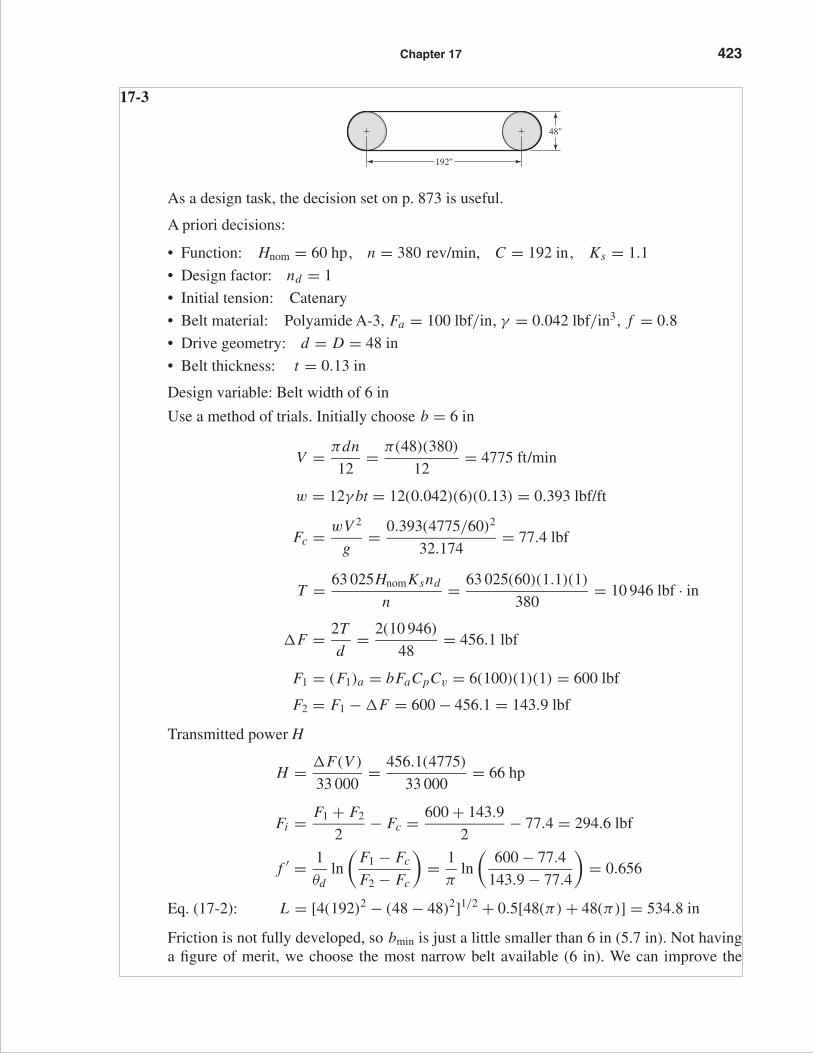
FIRST PAGES
Chapter 17 423
17-3
As a design task, the decision set on p. 873 is useful.
A priori decisions:
• Function: Hnom = 60 hp, n = 380 rev/min, C = 192 in, Ks = 1.1
• Design factor: nd = 1
• Initial tension: Catenary
• Belt material: Polyamide A-3, Fa = 100 lbf/in, γ = 0.042 lbf/in3, f = 0.8
• Drive geometry: d = D = 48 in
• Belt thickness: t = 0.13 in
Design variable: Belt width of 6 in
Use a method of trials. Initially choose b = 6 in
V = πdn
12= π(48)(380)
12= 4775 ft/min
w = 12γ bt = 12(0.042)(6)(0.13) = 0.393 lbf/ft
Fc = wV 2
g= 0.393(4775/60)2
32.174= 77.4 lbf
T = 63 025HnomKsnd
n= 63 025(60)(1.1)(1)
380= 10 946 lbf · in
�F = 2T
d= 2(10 946)
48= 456.1 lbf
F1 = (F1)a = bFaCpCv = 6(100)(1)(1) = 600 lbf
F2 = F1 − �F = 600 − 456.1 = 143.9 lbf
Transmitted power H
H = �F(V )
33 000= 456.1(4775)
33 000= 66 hp
Fi = F1 + F2
2− Fc = 600 + 143.9
2− 77.4 = 294.6 lbf
f ′ = 1
θdln
(F1 − Fc
F2 − Fc
)= 1
πln
(600 − 77.4
143.9 − 77.4
)= 0.656
Eq. (17-2): L = [4(192)2 − (48 − 48)2]1/2 + 0.5[48(π) + 48(π)] = 534.8 in
Friction is not fully developed, so bmin is just a little smaller than 6 in (5.7 in). Not havinga figure of merit, we choose the most narrow belt available (6 in). We can improve the
48"
192"
budynas_SM_ch17.qxd 12/06/2006 17:29 Page 423

FIRST PAGES
424 Solutions Manual • Instructor’s Solution Manual to Accompany Mechanical Engineering Design
design by reducing the initial tension, which reduces F1 and F2, thereby increasing belt life.This will bring f ′ to 0.80
F1 = (�F + Fc) exp( f θ) − Fc
exp( f θ) − 1
exp( f θ) = exp(0.80π) = 12.345
Therefore
F1 = (456.1 + 77.4)(12.345) − 77.4
12.345 − 1= 573.7 lbf
F2 = F1 − �F = 573.7 − 456.1 = 117.6 lbf
Fi = F1 + F2
2− Fc = 573.7 + 117.6
2− 77.4 = 268.3 lbf
These are small reductions since f ′ is close to f, but improvements nevertheless.
dip = 3C2w
2Fi= 3(192/12)2(0.393)
2(268.3)= 0.562 in
17-4 From the last equation given in the Problem Statement,
exp( f φ) = 1
1 − {2T/[d(a0 − a2)b]}[1 − 2T
d(a0 − a2)b
]exp( f φ) = 1
[2T
d(a0 − a2)b
]exp( f φ) = exp( f φ) − 1
b = 1
a0 − a2
(2T
d
)[exp( f φ)
exp( f φ) − 1
]
But 2T/d = 33 000Hd/V
Thus,
b = 1
a0 − a2
(33 000Hd
V
)[exp( f φ)
exp( f φ) − 1
]Q.E .D.
17-5 Refer to Ex. 17-1 on p. 870 for the values used below.
(a) The maximum torque prior to slip is,
T = 63 025HnomKsnd
n= 63 025(15)(1.25)(1.1)
1750= 742.8 lbf · in Ans.
The corresponding initial tension is,
Fi = T
D
(exp( f θ) + 1
exp( f θ) − 1
)= 742.8
6
(11.17 + 1
11.17 − 1
)= 148.1 lbf Ans.
budynas_SM_ch17.qxd 12/06/2006 17:29 Page 424

FIRST PAGES
Chapter 17 425
(b) See Prob. 17-4 statement. The final relation can be written
bmin = 1
FaCpCv − (12γ t/32.174)(V/60)2
{33 000Ha exp( f θ)
V [exp( f θ) − 1]
}
= 1
100(0.7)(1) −{[12(0.042)(0.13)]/32.174}(2749/60)2
[33 000(20.6)(11.17)
2749(11.17 − 1)
]
= 4.13 in Ans.
This is the minimum belt width since the belt is at the point of slip. The design mustround up to an available width.
Eq. (17-1):
θd = π − 2 sin−1(
D − d
2C
)= π − 2 sin−1
[18 − 6
2(96)
]
= 3.016 511 rad
θD = π + 2 sin−1(
D − d
2C
)= π + 2 sin−1
[18 − 6
2(96)
]
= 3.266 674
Eq. (17-2):
L = [4(96)2 − (18 − 6)2]1/2 + 1
2[18(3.266 674) + 6(3.016 511)]
= 230.074 in Ans.
(c) �F = 2T
d= 2(742.8)
6= 247.6 lbf
(F1)a = bFaCpCv = F1 = 4.13(100)(0.70)(1) = 289.1 lbf
F2 = F1 − �F = 289.1 − 247.6 = 41.5 lbf
Fc = 25.6
(0.271
0.393
)= 17.7 lbf
Fi = F1 + F2
2− Fc = 289.1 + 41.5
2− 17.7 = 147.6 lbf
Transmitted belt power H
H = �F(V )
33 000= 247.6(2749)
33 000= 20.6 hp
n f s = H
HnomKs= 20.6
15(1.25)= 1.1
budynas_SM_ch17.qxd 12/06/2006 17:29 Page 425

FIRST PAGES
426 Solutions Manual • Instructor’s Solution Manual to Accompany Mechanical Engineering Design
If you only change the belt width, the parameters in the following table change as shown.
Ex. 17-1 This Problem
b 6.00 4.13w 0.393 0.271Fc 25.6 17.6(F1)a 420 289F2 172.4 42Fi 270.6 147.7f ′ 0.33* 0.80**dip 0.139 0.176
*Friction underdeveloped**Friction fully developed
17-6 The transmitted power is the same.
n-Foldb = 6 in b = 12 in Change
Fc 25.65 51.3 2Fi 270.35 664.9 2.46(F1)a 420 840 2F2 172.4 592.4 3.44Ha 20.62 20.62 1nfs 1.1 1.1 1f ′ 0.139 0.125 0.90dip 0.328 0.114 0.34
If we relax Fi to develop full friction ( f = 0.80) and obtain longer life, then
n-Foldb = 6 in b = 12 in Change
Fc 25.6 51.3 2Fi 148.1 148.1 1F1 297.6 323.2 1.09F2 50 75.6 1.51f ′ 0.80 0.80 1dip 0.255 0.503 2
budynas_SM_ch17.qxd 12/06/2006 17:29 Page 426

FIRST PAGES
Chapter 17 427
17-7
Find the resultant of F1 and F2 :
α = sin−1 D − d
2C
sin α = D − d
2C
cos α = 1 − 1
2
(D − d
2C
)2
Rx = F1 cos α + F2 cos α = (F1 + F2)
[1 − 1
2
(D − d
2C
)2]
Ans.
Ry = F1 sin α − F2 sin α = (F1 − F2)D − d
2CAns.
From Ex. 17-2, d = 16 in, D = 36 in, C = 16(12) = 192 in, F1 = 940 lbf, F2 = 276 lbf
α = sin−1[
36 − 16
2(192)
]= 2.9855◦
Rx = (940 + 276)
[1 − 1
2
(36 − 16
2(192)
)2]
= 1214.4 lbf
Ry = (940 − 276)
[36 − 16
2(192)
]= 34.6 lbf
T = (F1 − F2)
(d
2
)= (940 − 276)
(16
2
)= 5312 lbf · in
17-8 Begin with Eq. (17-10),
F1 = Fc + Fi2 exp( f θ)
exp( f θ) − 1
Introduce Eq. (17-9):
F1 = Fc + T
D
[exp( f θ) + 1
exp( f θ) − 1
] [2 exp( f θ)
exp( f θ) + 1
]= Fc + 2T
D
[exp( f θ)
exp( f θ) − 1
]
F1 = Fc + �F
[exp( f θ)
exp( f θ) − 1
]
d D
C
F1
Rx
Ryx
y
F2
�
�
budynas_SM_ch17.qxd 12/06/2006 17:29 Page 427

FIRST PAGES
428 Solutions Manual • Instructor’s Solution Manual to Accompany Mechanical Engineering Design
Now add and subtract Fc
[exp( f θ)
exp( f θ) − 1
]
F1 = Fc + Fc
[exp( f θ)
exp( f θ) − 1
]+ �F
[exp( f θ)
exp( f θ) − 1
]− Fc
[exp( f θ)
exp( f θ) − 1
]
F1 = (Fc + �F)
[exp( f θ)
exp( f θ) − 1
]+ Fc − Fc
[exp( f θ)
exp( f θ) − 1
]
F1 = (Fc + �F)
[exp( f θ)
exp( f θ) − 1
]− Fc
exp( f θ) − 1
F1 = (Fc + �F) exp( f θ) − Fc
exp( f θ) − 1Q.E.D.
From Ex. 17-2: θd = 3.037 rad, �F = 664 lbf, exp( f θ) = exp[0.80(3.037)] = 11.35,and Fc = 73.4 lbf.
F1 = (73.4 + 664)(11.35 − 73.4)
(11.35 − 1)= 802 lbf
F2 = F1 − �F = 802 − 664 = 138 lbf
Fi = 802 + 138
2− 73.4 = 396.6 lbf
f ′ = 1
θdln
(F1 − Fc
F2 − Fc
)= 1
3.037ln
(802 − 73.4
138 − 73.4
)= 0.80 Ans.
17-9 This is a good class project. Form four groups, each with a belt to design. Once each groupagrees internally, all four should report their designs including the forces and torques on theline shaft. If you give them the pulley locations, they could design the line shaft.
17-10 If you have the students implement a computer program, the design problem selectionsmay differ, and the students will be able to explore them. For Ks = 1.25, nd = 1.1,d = 14 in and D = 28 in, a polyamide A-5 belt, 8 inches wide, will do (bmin = 6.58 in)
17-11 An efficiency of less than unity lowers the output for a given input. Since the object of thedrive is the output, the efficiency must be incorporated such that the belt’s capacity isincreased. The design power would thus be expressed as
Hd = HnomKsnd
effAns.
17-12 Some perspective on the size of Fc can be obtained from
Fc = w
g
(V
60
)2
= 12γ bt
g
(V
60
)2
budynas_SM_ch17.qxd 12/06/2006 17:29 Page 428

FIRST PAGES
Chapter 17 429
An approximate comparison of non-metal and metal belts is presented in the tablebelow.
Non-metal Metal
γ , lbf/in3 0.04 0.280b, in 5.00 1.000t , in 0.20 0.005
The ratio w/wm is
w
wm= 12(0.04)(5)(0.2)
12(0.28)(1)(0.005)= 29
The second contribution to Fc is the belt peripheral velocity which tends to be low inmetal belts used in instrument, printer, plotter and similar drives. The velocity ratiosquared influences any Fc/(Fc)m ratio.
It is common for engineers to treat Fc as negligible compared to other tensions in thebelting problem. However, when developing a computer code, one should include Fc .
17-13 Eq. (17-8):
�F = F1 − F2 = (F1 − Fc)exp( f θ) − 1
exp( f θ)
Assuming negligible centrifugal force and setting F1 = ab from step 3,
bmin = �F
a
[exp( f θ)
exp( f θ) − 1
](1)
Also, Hd = HnomKsnd = (�F)V
33 000
�F = 33 000HnomKsnd
V
Substituting into (1), bmin = 1
a
(33 000Hd
V
)exp( f θ)
exp( f θ) − 1Ans.
17-14 The decision set for the friction metal flat-belt drive is:
A priori decisions
• Function: Hnom = 1 hp , n = 1750 rev/min , V R = 2 , C = 15 in , Ks = 1.2 ,Np = 106 belt passes.
• Design factor: nd = 1.05
• Belt material and properties: 301/302 stainless steel
Table 17-8: Sy = 175 000 psi, E = 28 Mpsi, ν = 0.285
budynas_SM_ch17.qxd 12/06/2006 17:29 Page 429

FIRST PAGES
430 Solutions Manual • Instructor’s Solution Manual to Accompany Mechanical Engineering Design
• Drive geometry: d = 2 in, D = 4 in• Belt thickness: t = 0.003 in
Design variables:
• Belt width b• Belt loop periphery
Preliminaries
Hd = HnomKsnd = 1(1.2)(1.05) = 1.26 hp
T = 63 025(1.26)
1750= 45.38 lbf · in
A 15 in center-to-center distance corresponds to a belt loop periphery of 39.5 in. The40 in loop available corresponds to a 15.254 in center distance.
θd = π − 2 sin−1[
4 − 2
2(15.254)
]= 3.010 rad
θD = π + 2 sin−1[
4 − 2
2(15.274)
]= 3.273 rad
For full friction development
exp( f θd) = exp[0.35(3.010)] = 2.868
V = πdn
12= π(2)(1750)
12= 916.3 ft/s
Sy = 175 000 psi
Eq. (17-15):
Sf = 14.17(106)(106)−0.407 = 51 212 psi
From selection step 3
a =[
Sf − Et
(1 − ν2)d
]t =
[51 212 − 28(106)(0.003)
(1 − 0.2852)(2)
](0.003)
= 16.50 lbf/in of belt width
(F1)a = ab = 16.50b
For full friction development, from Prob. 17-13,
bmin = �F
a
exp( f θd)
exp( f θd) − 1
�F = 2T
d= 2(45.38)
2= 45.38 lbf
So
bmin = 45.38
16.50
(2.868
2.868 − 1
)= 4.23 in
budynas_SM_ch17.qxd 12/06/2006 17:29 Page 430

FIRST PAGES
Chapter 17 431
Decision #1: b = 4.5 in
F1 = (F1)a = ab = 16.5(4.5) = 74.25 lbf
F2 = F1 − �F = 74.25 − 45.38 = 28.87 lbf
Fi = F1 + F2
2= 74.25 + 28.87
2= 51.56 lbf
Existing friction
f ′ = 1
θdln
(F1
F2
)= 1
3.010ln
(74.25
28.87
)= 0.314
Ht = (�F)V
33 000= 45.38(916.3)
33 000= 1.26 hp
n f s = Ht
HnomKs= 1.26
1(1.2)= 1.05
This is a non-trivial point. The methodology preserved the factor of safety correspondingto nd = 1.1 even as we rounded bmin up to b .
Decision #2 was taken care of with the adjustment of the center-to-center distance toaccommodate the belt loop. Use Eq. (17-2) as is and solve for C to assist in this. Remem-ber to subsequently recalculate θd and θD .
17-15 Decision set:
A priori decisions
• Function: Hnom = 5 hp, N = 1125 rev/min, V R = 3, C = 20 in, Ks = 1.25,
Np = 106 belt passes• Design factor: nd = 1.1• Belt material: BeCu, Sy = 170 000 psi, E = 17(106) psi, ν = 0.220• Belt geometry: d = 3 in, D = 9 in• Belt thickness: t = 0.003 in
Design decisions
• Belt loop periphery• Belt width b
Preliminaries:
Hd = HnomKsnd = 5(1.25)(1.1) = 6.875 hp
T = 63 025(6.875)
1125= 385.2 lbf · in
Decision #1: Choose a 60-in belt loop with a center-to-center distance of 20.3 in.
θd = π − 2 sin−1[
9 − 3
2(20.3)
]= 2.845 rad
θD = π + 2 sin−1[
9 − 3
2(20.3)
]= 3.438 rad
budynas_SM_ch17.qxd 12/06/2006 17:29 Page 431

FIRST PAGES
432 Solutions Manual • Instructor’s Solution Manual to Accompany Mechanical Engineering Design
For full friction development:
exp( f θd) = exp[0.32(2.845)] = 2.485
V = πdn
12= π(3)(1125)
12= 883.6 ft/min
Sf = 56 670 psi
From selection step 3
a =[
Sf − Et
(1 − ν2)d
]t =
[56 670 − 17(106)(0.003)
(1 − 0.222)(3)
](0.003) = 116.4 lbf/in
�F = 2T
d= 2(385.2)
3= 256.8 lbf
bmin = �F
a
[exp( f θd)
exp( f θd) − 1
]= 256.8
116.4
(2.485
2.485 − 1
)= 3.69 in
Decision #2: b = 4 in
F1 = (F1)a = ab = 116.4(4) = 465.6 lbf
F2 = F1 − �F = 465.6 − 256.8 = 208.8 lbf
Fi = F1 + F2
2= 465.6 + 208.8
2= 337.3 lbf
Existing friction
f ′ = 1
θdln
(F1
F2
)= 1
2.845ln
(465.6
208.8
)= 0.282
H = (�F)V
33 000= 256.8(883.6)
33 000= 6.88 hp
n f s = H
5(1.25)= 6.88
5(1.25)= 1.1
Fi can be reduced only to the point at which f ′ = f = 0.32. From Eq. (17-9)
Fi = T
d
[exp( f θd) + 1
exp( f θd) − 1
]= 385.2
3
(2.485 + 1
2.485 − 1
)= 301.3 lbf
Eq. (17-10):
F1 = Fi
[2 exp( f θd)
exp( f θd) + 1
]= 301.3
[2(2.485)
2.485 + 1
]= 429.7 lbf
F2 = F1 − �F = 429.7 − 256.8 = 172.9 lbf
and f ′ = f = 0.32
17-16 This solution is the result of a series of five design tasks involving different belt thick-nesses. The results are to be compared as a matter of perspective. These design tasks areaccomplished in the same manner as in Probs. 17-14 and 17-15 solutions.
budynas_SM_ch17.qxd 12/06/2006 17:29 Page 432

FIRST PAGES
Chapter 17 433
The details will not be presented here, but the table is provided as a means of learning.Five groups of students could each be assigned a belt thickness. You can form a table fromtheir results or use the table below
t , in
0.002 0.003 0.005 0.008 0.010
b 4.000 3.500 4.000 1.500 1.500CD 20.300 20.300 20.300 18.700 20.200a 109.700 131.900 110.900 194.900 221.800d 3.000 3.000 3.000 5.000 6.000D 9.000 9.000 9.000 15.000 18.000Fi 310.600 333.300 315.200 215.300 268.500F1 439.000 461.700 443.600 292.300 332.700F2 182.200 209.000 186.800 138.200 204.300n f s 1.100 1.100 1.100 1.100 1.100L 60.000 60.000 60.000 70.000 80.000f ′ 0.309 0.285 0.304 0.288 0.192Fi 301.200 301.200 301.200 195.700 166.600F1 429.600 429.600 429.600 272.700 230.800F2 172.800 172.800 172.800 118.700 102.400f 0.320 0.320 0.320 0.320 0.320
The first three thicknesses result in the same adjusted Fi , F1 and F2 (why?). We have nofigure of merit, but the costs of the belt and the pulleys is about the same for these threethicknesses. Since the same power is transmitted and the belts are widening, belt forcesare lessening.
17-17 This is a design task. The decision variables would be belt length and belt section, whichcould be combined into one, such as B90. The number of belts is not an issue.
We have no figure of merit, which is not practical in a text for this application. I sug-gest you gather sheave dimensions and costs and V-belt costs from a principal vendor andconstruct a figure of merit based on the costs. Here is one trial.
Preliminaries: For a single V-belt drive with Hnom = 3 hp, n = 3100 rev/min,D = 12 in, and d = 6.2 in, choose a B90 belt, Ks = 1.3 and nd = 1.
L p = 90 + 1.8 = 91.8 inEq. (17-16b):
C = 0.25
[
91.8 − π
2(12 + 6.2)
]+
√[91.8 − π
2(12 + 6.2)
]2
− 2(12 − 6.2)2
= 31.47 in
θd = π − 2 sin−1[
12 − 6.2
2(31.47)
]= 2.9570 rad
exp( f θd) = exp[0.5123(2.9570)] = 4.5489
V = πdn
12= π(6.2)(3100)
12= 5031.8 ft/min
budynas_SM_ch17.qxd 12/06/2006 17:29 Page 433

FIRST PAGES
434 Solutions Manual • Instructor’s Solution Manual to Accompany Mechanical Engineering Design
Table 17-13:
Angle θ = θd180°
π= (2.957 rad)
(180°
π
)= 169.42°
The footnote regression equation gives K1 without interpolation:
K1 = 0.143 543 + 0.007 468(169.42°) − 0.000 015 052(169.42°)2 = 0.9767
The design power is
Hd = HnomKsnd = 3(1.3)(1) = 3.9 hp
From Table 17-14 for B90, K2 = 1. From Table 17-12 take a marginal entry of Htab = 4,although extrapolation would give a slightly lower Htab .
Eq. (17-17): Ha = K1K2 Htab
= 0.9767(1)(4) = 3.91 hp
The allowable �Fa is given by
�Fa = 63 025Ha
n(d/2)= 63 025(3.91)
3100(6.2/2)= 25.6 lbf
The allowable torque Ta is
Ta = �Fad
2= 25.6(6.2)
2= 79.4 lbf · in
From Table 17-16, Kc = 0.965. Thus, Eq. (17-21) gives,
Fc = 0.965
(5031.8
1000
)2
= 24.4 lbf
At incipient slip, Eq. (17-9) provides:
Fi =(
T
d
)[exp( f θ) + 1
exp( f θ) − 1
]=
(79.4
6.2
)(4.5489 + 1
4.5489 − 1
)= 20.0 lbf
Eq. (17-10):
F1 = Fc + Fi
[2 exp( f θ)
exp( f θ) + 1
]= 24.4 + 20
[2(4.5489)
4.5489 + 1
]= 57.2 lbf
Thus, F2 = F1 − �Fa = 57.2 − 25.6 = 31.6 lbf
Eq. (17-26): n f s = Ha Nb
Hd= (3.91)(1)
3.9= 1.003 Ans.
If we had extrapolated for Htab, the factor of safety would have been slightly lessthan one.
Life Use Table 17-16 to find equivalent tensions T1 and T2 .
T1 = F1 + (Fb)1 = F1 + Kb
d= 57.2 + 576
6.2= 150.1 lbf
T2 = F1 + (Fb)2 = F1 + Kb
D= 57.2 + 576
12= 105.2 lbf
budynas_SM_ch17.qxd 12/06/2006 17:29 Page 434

FIRST PAGES
Chapter 17 435
From Eq. (17-27), the number of belt passes is:
NP =[(
1193
150.1
)−10.929
+(
1193
105.2
)−10.929]−1
= 6.76(109)
From Eq. (17-28) for NP > 109 ,
t = NP L p
720V>
109(91.8)
720(5031.8)
t > 25 340 h Ans.
Suppose n f s was too small. Compare these results with a 2-belt solution.
Htab = 4 hp/belt, Ta = 39.6 lbf · in/belt,
�Fa = 12.8 lbf/belt, Ha = 3.91 hp/belt
n f s = Nb Ha
Hd= Nb Ha
HnomKs= 2(3.91)
3(1.3)= 2.0
Also, F1 = 40.8 lbf/belt, F2 = 28.0 lbf/belt,
Fi = 9.99 lbf/belt, Fc = 24.4 lbf/belt
(Fb)1 = 92.9 lbf/belt, (Fb)2 = 48 lbf/belt
T1 = 133.7 lbf/belt, T2 = 88.8 lbf/belt
NP = 2.39(1010) passes, t > 605 600 h
Initial tension of the drive:
(Fi )drive = Nb Fi = 2(9.99) = 20 lbf
17-18 Given: two B85 V-belts with d = 5.4 in, D = 16 in, n = 1200 rev/min, and Ks = 1.25
Table 17-11: L p = 85 + 1.8 = 86.8 in
Eq. (17-17b):
C = 0.25
[
86.8 − π
2(16 + 5.4)
]+
√[86.8 − π
2(16 + 5.4)
]2
− 2(16 − 5.4)2
= 26.05 in Ans.
Eq. (17-1):
θd = 180° − 2 sin−1[
16 − 5.4
2(26.05)
]= 156.5°
From table 17-13 footnote:
K1 = 0.143 543 + 0.007 468(156.5°) − 0.000 015 052(156.5°)2 = 0.944
Table 17-14: K2 = 1
Belt speed: V = π(5.4)(1200)
12= 1696 ft/min
budynas_SM_ch17.qxd 12/06/2006 17:29 Page 435

FIRST PAGES
436 Solutions Manual • Instructor’s Solution Manual to Accompany Mechanical Engineering Design
Use Table 17-12 to interpolate for Htab.
Htab = 1.59 +(
2.62 − 1.59
2000 − 1000
)(1696 − 1000) = 2.31 hp/belt
Ha = K1K2 Nb Htab = 1(0.944)(2)(2.31) = 4.36 hp
Assuming nd = 1
Hd = Ks Hnomnd = 1.25(1)Hnom
For a factor of safety of one,
Ha = Hd
4.36 = 1.25Hnom
Hnom = 4.36
1.25= 3.49 hp Ans.
17-19 Given: Hnom = 60 hp, n = 400 rev/min, Ks = 1.4, d = D = 26 in on 12 ft centers.Design task: specify V-belt and number of strands (belts). Tentative decision: Use D360 belts.
Table 17-11: L p = 360 + 3.3 = 363.3 in
Eq. (17-16b):
C = 0.25
[363.3 − π
2(26 + 26)
]+
√[363.3 − π
2(26 + 26)
]2
− 2(26 − 26)2
= 140.8 in (nearly 144 in)
θd = π, θD = π, exp[0.5123π] = 5.0,
V = πdn
12= π(26)(400)
12= 2722.7 ft/min
Table 17-13: For θ = 180°, K1 = 1
Table 17-14: For D360, K2 = 1.10
Table 17-12: Htab = 16.94 hp by interpolation
Thus, Ha = K1K2 Htab = 1(1.1)(16.94) = 18.63 hp
Hd = Ks Hnom = 1.4(60) = 84 hp
Number of belts, Nb
Nb = Ks Hnom
K1K2 Htab= Hd
Ha= 84
18.63= 4.51
Round up to five belts. It is left to the reader to repeat the above for belts such as C360and E360.
�Fa = 63 025Ha
n(d/2)= 63 025(18.63)
400(26/2)= 225.8 lbf/belt
Ta = (�Fa)d
2= 225.8(26)
2= 2935 lbf · in/belt
budynas_SM_ch17.qxd 12/06/2006 17:29 Page 436

FIRST PAGES
Chapter 17 437
Eq. (17-21):
Fc = 3.498
(V
1000
)2
= 3.498
(2722.7
1000
)2
= 25.9 lbf/belt
At fully developed friction, Eq. (17-9) gives
Fi = T
d
[exp( f θ) + 1
exp( f θ) − 1
]= 2935
26
(5 + 1
5 − 1
)= 169.3 lbf/belt
Eq. (17-10): F1 = Fc + Fi
[2 exp( f θ)
exp( f θ) + 1
]= 25.9 + 169.3
[2(5)
5 + 1
]= 308.1 lbf/belt
F2 = F1 − �Fa = 308.1 − 225.8 = 82.3 lbf/belt
n f s = Ha Nb
Hd= (185.63)
84= 1.109 Ans.
Reminder: Initial tension is for the drive
(Fi )drive = Nb Fi = 5(169.3) = 846.5 lbf
A 360 belt is at the right-hand edge of the range of center-to-center pulley distances.
D ≤ C ≤ 3(D + d)
26 ≤ C ≤ 3(26 + 26)
17-20 Preliminaries: D = 60 in, 14-in wide rim, Hnom = 50 hp, n = 875 rev/min, Ks = 1.2,nd = 1.1, mG = 875/170 = 5.147, d = 60/5.147 = 11.65 in
(a) From Table 17-9, an 11-in sheave exceeds C-section minimum diameter and pre-cludes D- and E-section V-belts.
Decision: Use d = 11 in, C270 belts
Table 17-11: L p = 270 + 2.9 = 272.9 in
C = 0.25
[
272.9 − π
2(60 + 11)
]+
√[272.9 − π
2(60 + 11)
]2
− 2(60 − 11)2
= 76.78 in
This fits in the rangeD < C < 3(D + d)
60 < C < 3(60 + 11)
60 in < C < 213 in
θd = π − 2 sin−1[
60 − 11
2(76.78)
]= 2.492 rad
θD = π + 2 sin−1[
60 − 11
2(76.78)
]= 3.791 rad
exp[0.5123(2.492)] = 3.5846
budynas_SM_ch17.qxd 12/06/2006 17:29 Page 437

FIRST PAGES
438 Solutions Manual • Instructor’s Solution Manual to Accompany Mechanical Engineering Design
For the flat on flywheel
exp[0.13(3.791)] = 1.637
V = πdn
12= π(11)(875)
12= 2519.8 ft/min
Table 17-13: Regression equation gives K1 = 0.90
Table 17-14: K2 = 1.15
Table 17-12: Htab = 7.83 hp/belt by interpolation
Eq. (17-17): Ha = K1K2 Htab = 0.905(1.15)(7.83) = 8.15 hp
Eq. (17-19): Hd = HnomKsnd = 50(1.2)(1.1) = 66 hp
Eq. (17-20): Nb = Hd
Ha= 66
8.15= 8.1 belts
Decision: Use 9 belts. On a per belt basis,
�Fa = 63 025Ha
n(d/2)= 63 025(8.15)
875(11/2)= 106.7 lbf/belt
Ta = �Fad
2= 106.7(11)
2= 586.9 lbf per belt
Fc = 1.716
(V
1000
)2
= 1.716
(2519.8
1000
)2
= 10.9 lbf/belt
At fully developed friction, Eq. (17-9) gives
Fi = T
d
[exp( f θd) + 1
exp( f θd) − 1
]= 586.9
11
(3.5846 + 1
3.5846 − 1
)= 94.6 lbf/belt
Eq. (17-10):
F1 = Fc + Fi
[2 exp( f θd)
exp( f θd) + 1
]= 10.9 + 94.6
[2(3.5846)
3.5846 + 1
]= 158.8 lbf/belt
F2 = F1 − �Fa = 158.8 − 106.7 = 52.1 lbf/belt
n f s = Nb Ha
Hd= 9(8.15)
66= 1.11 O.K. Ans.
Durability:(Fb)1 = 145.45 lbf/belt, (Fb)2 = 76.7 lbf/belt
T1 = 304.4 lbf/belt, T2 = 185.6 lbf/belt
and t > 150 000 h
Remember: (Fi )drive = 9(94.6) = 851.4 lbf
Table 17-9: C-section belts are 7/8" wide. Check sheave groove spacing to see if14"-width is accommodating.
budynas_SM_ch17.qxd 12/06/2006 17:29 Page 438

FIRST PAGES
Chapter 17 439
(b) The fully developed friction torque on the flywheel using the flats of the V-belts is
Tflat = �Fi
[exp( f θ) − 1
exp( f θ) + 1
]= 60(94.6)
(1.637 − 1
1.637 + 1
)= 1371 lbf · in per belt
The flywheel torque should be
Tfly = mG Ta = 5.147(586.9) = 3021 lbf · in per belt
but it is not. There are applications, however, in which it will work. For example,make the flywheel controlling. Yes. Ans.
17-21
(a) S is the spliced-in string segment length
De is the equatorial diameter
D′ is the spliced string diameter
δ is the radial clearance
S + π De = π D′ = π(De + 2δ) = π De + 2πδ
From which
δ = S
2π
The radial clearance is thus independent of De .
δ = 12(6)
2π= 11.5 in Ans.
This is true whether the sphere is the earth, the moon or a marble. Thinking in termsof a radial or diametral increment removes the basic size from the problem. Viewpointagain!
(b) and (c)
Table 17-9: For an E210 belt, the thickness is 1 in.
dP − di = 210 + 4.5
π− 210
π= 4.5
π
2δ = 4.5
π
δ = 4.5
2π= 0.716 in
0.716"1"
dp
Dp
�
�
Pitch surface
60"
D�
S
De �
budynas_SM_ch17.qxd 12/06/2006 17:29 Page 439

FIRST PAGES
440 Solutions Manual • Instructor’s Solution Manual to Accompany Mechanical Engineering Design
The pitch diameter of the flywheel is
DP − 2δ = D
DP = D + 2δ = 60 + 2(0.716) = 61.43 in
We could make a table:
Diametral SectionGrowth A B C D E
2δ1.3
π
1.8
π
2.9
π
3.3
π
4.5
π
The velocity ratio for the D-section belt of Prob. 17-20 is
m′G = D + 2δ
d= 60 + 3.3/π
11= 5.55 Ans.
for the V-flat drive as compared to ma = 60/11 = 5.455 for the VV drive.
The pitch diameter of the pulley is still d = 11 in, so the new angle of wrap, θd, is
θd = π − 2 sin−1(
D + 2δ − d
2C
)Ans.
θD = π + 2 sin−1(
D + 2δ − d
2C
)Ans.
Equations (17-16a) and (17-16b) are modified as follows
L p = 2C + π
2(D + 2δ + d) + (D + δ − d)2
4CAns.
Cp = 0.25
[L p − π
2(D + 2δ + d)
]
+√[
L p − π
2(D + 2δ + d)
]2
− 2(D + 2δ − d)2
Ans.
The changes are small, but if you are writing a computer code for a V-flat drive,remember that θd and θD changes are exponential.
17-22 This design task involves specifying a drive to couple an electric motor running at1720 rev/min to a blower running at 240 rev/min, transmitting two horsepower with acenter distance of at least 22 inches. Instead of focusing on the steps, we will display twodifferent designs side-by-side for study. Parameters are in a “per belt” basis with per drivequantities shown along side, where helpful.
budynas_SM_ch17.qxd 12/06/2006 17:29 Page 440

FIRST PAGES
Chapter 17 441
Parameter Four A-90 Belts Two A-120 Belts
mG 7.33 7.142Ks 1.1 1.1nd 1.1 1.1K1 0.877 0.869K2 1.05 1.15d, in 3.0 4.2D, in 22 30θd , rad 2.333 2.287V, ft/min 1350.9 1891exp( f θd) 3.304 3.2266L p, in 91.3 101.3C, in 24.1 31
Htab, uncorr. 0.783 1.662Nb Htab, uncorr. 3.13 3.326Ta , lbf · in 26.45(105.8) 60.87(121.7)�Fa , lbf 17.6(70.4) 29.0(58)Ha , hp 0.721(2.88) 1.667(3.33)n f s 1.192 1.372F1, lbf 26.28(105.2) 44(88)F2, lbf 8.67(34.7) 15(30)(Fb)1, lbf 73.3(293.2) 52.4(109.8)(Fb)2, lbf 10(40) 7.33(14.7)Fc, lbf 1.024 2.0Fi , lbf 16.45(65.8) 27.5(55)T1, lbf · in 99.2 96.4T2, lbf · in 36.3 57.4N ′, passes 1.61(109) 2.3(109)t > h 93 869 89 080
Conclusions:
• Smaller sheaves lead to more belts.
• Larger sheaves lead to larger D and larger V.
• Larger sheaves lead to larger tabulated power.
• The discrete numbers of belts obscures some of the variation. The factors of safetyexceed the design factor by differing amounts.
17-23 In Ex. 17-5 the selected chain was 140-3, making the pitch of this 140 chain14/8 = 1.75 in.Table 17-19 confirms.
17-24
(a) Eq. (17-32): H1 = 0.004N 1.081 n0.9
1 p(3−0.07p)
Eq. (17-33): H2 = 1000Kr N 1.51 p0.8
n1.51
budynas_SM_ch17.qxd 12/06/2006 17:29 Page 441

FIRST PAGES
442 Solutions Manual • Instructor’s Solution Manual to Accompany Mechanical Engineering Design
Equating and solving for n1 gives
n1 =[
0.25(106)Kr N 0.421
p(2.2−0.07p)
]1/2.4
Ans.
(b) For a No. 60 chain, p = 6/8 = 0.75 in, N1 = 17, Kr = 17
n1 ={
0.25(106)(17)(17)0.42
0.75[2.2−0.07(0.75)]
}1/2.4
= 1227 rev/min Ans.
Table 17-20 confirms that this point occurs at 1200 ± 200 rev/min.
(c) Life predictions using Eq. (17-40) are possible at speeds greater than 1227 rev/min. Ans.
17-25 Given: a double strand No. 60 roller chain with p = 0.75 in, N1 = 13 teeth at 300 rev/min,N2 = 52 teeth.
(a) Table 17-20: Htab = 6.20 hp
Table 17-22: K1 = 0.75
Table 17-23: K2 = 1.7
Use Ks = 1
Eq. (17-37):
Ha = K1K2 Htab = 0.75(1.7)(6.20) = 7.91 hp Ans.
(b) Eqs. (17-35) and (17-36) with L/p = 82
A = 13 + 52
2− 82 = −49.5 [
C = p
4
49.5 +
√49.52 − 8
(52 − 13
2π
)2 = 23.95p
C = 23.95(0.75) = 17.96 in, round up to 18 in Ans.
(c) For 30 percent less power transmission,
H = 0.7(7.91) = 5.54 hp
T = 63 025(5.54)
300= 1164 lbf · in Ans.
Eq. (17-29):
D = 0.75
sin(180◦/13)= 3.13 in
F = T
r= 1164
3.13/2= 744 lbf Ans.
budynas_SM_ch17.qxd 12/06/2006 17:29 Page 442

FIRST PAGES
Chapter 17 443
17-26 Given: No. 40-4 chain, N1 = 21 teeth for n = 2000 rev/min, N2 = 84 teeth,h = 20 000 hours.
(a) Chain pitch is p = 4/8 = 0.500 in and C = 20 in.
Eq. (17-34):L
p= 2(20)
0.5+ 21 + 84
2+ (84 − 21)2
4π2(20/0.5)= 135 pitches (or links)
L = 135(0.500) = 67.5 in Ans.
(b) Table 17-20: Htab = 7.72 hp (post-extreme power)
Eq. (17-40): Since K1 is required, the N 3.751 term is omitted.
const =(7.722.5
)(15 000)
135= 18 399
H ′tab =
[18 399(135)
20 000
]1/2.5
= 6.88 hp Ans.
(c) Table 17-22:
K1 =(
21
17
)1.5
= 1.37
Table 17-23: K2 = 3.3
Ha = K1K2 H ′tab = 1.37(3.3)(6.88) = 31.1 hp Ans.
(d) V = N1 pn
12= 21(0.5)(2000)
12= 1750 ft/min
F1 = 33 000(31.1)
1750= 586 lbf Ans.
17-27 This is our first design/selection task for chain drives. A possible decision set:
A priori decisions
• Function: Hnom, n1, space, life, Ks
• Design factor: nd
• Sprockets: Tooth counts N1 and N2, factors K1 and K2
Decision variables
• Chain number
• Strand count
• Lubrication type
• Chain length in pitches
Function: Motor with Hnom = 25 hp at n = 700 rev/min; pump at n = 140 rev/min;mG = 700/140 = 5
Design Factor: nd = 1.1
Sprockets: Tooth count N2 = mG N1 = 5(17) = 85 teeth–odd and unavailable. Choose 84 teeth. Decision: N1 = 17, N2 = 84
budynas_SM_ch17.qxd 12/06/2006 17:29 Page 443

FIRST PAGES
444 Solutions Manual • Instructor’s Solution Manual to Accompany Mechanical Engineering Design
Evaluate K1 and K2
Eq. (17-38): Hd = HnomKsnd
Eq. (17-37): Ha = K1K2 Htab
Equate Hd to Ha and solve for Htab :
Htab = Ksnd Hnom
K1K2
Table 17-22: K1 = 1
Table 17-23: K2 = 1, 1.7, 2.5, 3.3 for 1 through 4 strands
H ′tab = 1.5(1.1)(25)
(1)K2= 41.25
K2
Prepare a table to help with the design decisions:
Chain Lub.Strands K2 H ′
tab No. Htab n f s Type
1 1.0 41.3 100 59.4 1.58 B2 1.7 24.3 80 31.0 1.40 B3 2.5 16.5 80 31.0 2.07 B4 3.3 12.5 60 13.3 1.17 B
Design Decisions
We need a figure of merit to help with the choice. If the best was 4 strands of No. 60chain, then
Decision #1 and #2: Choose four strand No. 60 roller chain with n f s = 1.17.
n f s = K1K2 Htab
Ks Hnom= 1(3.3)(13.3)
1.5(25)= 1.17
Decision #3: Choose Type B lubrication
Analysis:
Table 17-20: Htab = 13.3 hp
Table 17-19: p = 0.75 in
Try C = 30 in in Eq. (17-34):
L
p= 2C
p+ N1 + N2
2+ (N2 − N1)
2
4π2C/p
= 2(30/0.75) + 17 + 84
2+ (84 − 17)2
4π2(30/0.75)
= 133.3 → 134
From Eq. (17-35) with p = 0.75 in,C = 30.26 in.
Decision #4: Choose C = 30.26 in.
budynas_SM_ch17.qxd 12/06/2006 17:29 Page 444

FIRST PAGES
Chapter 17 445
17-28 Follow the decision set outlined in Prob. 17-27 solution. We will form two tables, the firstfor a 15 000 h life goal, and a second for a 50 000 h life goal. The comparison is useful.
Function: Hnom = 50 hp at n = 1800 rev/min, npump = 900 rev/minmG = 1800/900 = 2, Ks = 1.2life = 15 000 h, then repeat with life = 50 000 h
Design factor: nd = 1.1
Sprockets: N1 = 19 teeth, N2 = 38 teeth
Table 17-22 (post extreme):
K1 =(
N1
17
)1.5
=(
19
17
)1.5
= 1.18
Table 17-23:
K2 = 1, 1.7, 2.5, 3.3, 3.9, 4.6, 6.0
Decision variables for 15 000 h life goal:
H ′tab = Ksnd Hnom
K1K2= 1.2(1.1)(50)
1.18K2= 55.9
K2(1)
n f s = K1K2 Htab
Ks Hnom= 1.18K2 Htab
1.2(50)= 0.0197K2 Htab
Form a table for a 15 000 h life goal using these equations.
K2 H ′tab Chain # Htab n f s Lub
1 1.0 55.90 120 21.6 0.423 C′2 1.7 32.90 120 21.6 0.923 C′3 2.5 22.40 120 21.6 1.064 C′4 3.3 16.90 120 21.6 1.404 C′5 3.9 14.30 80 15.6 1.106 C′6 4.6 12.20 60 12.4 1.126 C′8 6.0 9.32 60 12.4 1.416 C′
There are 4 possibilities where n f s ≥ 1.1
Decision variables for 50 000 h life goal
From Eq. (17-40), the power-life tradeoff is:
(H ′tab)
2.515 000 = (H ′′tab)
2.550 000
H ′′tab =
[15 000
50 000(H ′
tab)2.5]1/2.5
= 0.618 H ′tab
Substituting from (1),
H ′′tab = 0.618
(55.9
K2
)= 34.5
K2
budynas_SM_ch17.qxd 12/06/2006 17:29 Page 445

FIRST PAGES
446 Solutions Manual • Instructor’s Solution Manual to Accompany Mechanical Engineering Design
The H ′′ notation is only necessary because we constructed the first table, which we nor-mally would not do.
n f s = K1K2 H ′′tab
Ks Hnom= K1K2(0.618H ′
tab)
Ks Hnom= 0.618[(0.0197)K2 Htab] = 0.0122K2 Htab
Form a table for a 50 000 h life goal.
K2 H ′′tab Chain # Htab n f s Lub
1 1.0 34.50 120 21.6 0.264 C′2 1.7 20.30 120 21.6 0.448 C′3 2.5 13.80 120 21.6 0.656 C′4 3.3 10.50 120 21.6 0.870 C′5 3.9 8.85 120 21.6 1.028 C′6 4.6 7.60 120 21.6 1.210 C′8 6.0 5.80 80 15.6 1.140 C′
There are two possibilities in the second table with n f s ≥ 1.1. (The tables allow for theidentification of a longer life one of the outcomes.) We need a figure of merit to help withthe choice; costs of sprockets and chains are thus needed, but is more information thanwe have.
Decision #1: #80 Chain (smaller installation) Ans.
n f s = 0.0122K2 Htab = 0.0122(8.0)(15.6) = 1.14 O.K .
Decision #2: 8-Strand, No. 80 Ans.
Decision #3: Type C′ Lubrication Ans.
Decision #4: p = 1.0 in, C is in midrange of 40 pitches
L
p= 2C
p+ N1 + N2
2+ (N2 − N1)2
4π2C/p
= 2(40) + 19 + 38
2+ (38 − 19)2
4π2(40)
= 108.7 ⇒ 110 even integer Ans.
Eq. (17-36):
A = N1 + N2
2− L
p= 19 + 38
2− 110 = −81.5
Eq. (17-35):C
p= 1
4
81.5 +
√81.52 − 8
(38 − 19
2π
)2 = 40.64
C = p(C/p) = 1.0(40.64) = 40.64 in (for reference) Ans.
budynas_SM_ch17.qxd 12/06/2006 17:29 Page 446

FIRST PAGES
Chapter 17 447
17-29 The objective of the problem is to explore factors of safety in wire rope. We will expressstrengths as tensions.
(a) Monitor steel 2-in 6 × 19 rope, 480 ft long
Table 17-2: Minimum diameter of a sheave is 30d = 30(2) = 60 in, preferably45(2) = 90 in. The hoist abuses the wire when it is bent around a sheave. Table 17-24gives the nominal tensile strength as 106 kpsi. The ultimate load is
Fu = (Su)nom Anom = 106
[π(2)2
4
]= 333 kip Ans.
The tensile loading of the wire is given by Eq. (17-46)
Ft =(
W
m+ wl
)(1 + a
g
)
W = 4(2) = 8 kip, m = 1
Table (17-24):
wl = 1.60d2l = 1.60(22)(480) = 3072 lbf or 3.072 kip
Therefore,
Ft = (8 + 3.072)
(1 + 2
32.2
)= 11.76 kip Ans.
Eq. (17-48):
Fb = Er dw Am
D
and for the 72-in drum
Fb = 12(106)(2/13)(0.38)(22)(10−3)
72= 39 kip Ans.
For use in Eq. (17-44), from Fig. 17-21
( p/Su) = 0.0014
Su = 240 kpsi, p. 908
Ff = 0.0014(240)(2)(72)
2= 24.2 kip Ans.
(b) Factors of safety
Static, no bending:
n = Fu
Ft= 333
11.76= 28.3 Ans.
Static, with bending:
Eq. (17-49): ns = Fu − Fb
Ft= 333 − 39
11.76= 25.0 Ans.
budynas_SM_ch17.qxd 12/06/2006 17:29 Page 447

FIRST PAGES
448 Solutions Manual • Instructor’s Solution Manual to Accompany Mechanical Engineering Design
Fatigue without bending:
n f = Ff
Ft= 24.2
11.76= 2.06 Ans.
Fatigue, with bending: For a life of 0.1(106) cycles, from Fig. 17-21
( p/Su) = 4/1000 = 0.004
Ff = 0.004(240)(2)(72)
2= 69.1 kip
Eq. (17-50): n f = 69.1 − 39
11.76= 2.56 Ans.
If we were to use the endurance strength at 106 cycles (Ff = 24.2 kip) the factor ofsafety would be less than 1 indicating 106 cycle life impossible.
Comments:
• There are a number of factors of safety used in wire rope analysis. They are differ-ent, with different meanings. There is no substitute for knowing exactly which fac-tor of safety is written or spoken.
• Static performance of a rope in tension is impressive.
• In this problem, at the drum, we have a finite life.
• The remedy for fatigue is the use of smaller diameter ropes, with multiple ropessupporting the load. See Ex. 17-6 for the effectiveness of this approach. It will alsobe used in Prob. 17-30.
• Remind students that wire ropes do not fail suddenly due to fatigue. The outerwires gradually show wear and breaks; such ropes should be retired. Periodic in-spections prevent fatigue failures by parting of the rope.
17-30 Since this is a design task, a decision set is useful.
A priori decisions
• Function: load, height, acceleration, velocity, life goal
• Design Factor: nd
• Material: IPS, PS, MPS or other
• Rope: Lay, number of strands, number of wires per strand
Decision variables:
• Nominal wire size: d
• Number of load-supporting wires: m
From experience with Prob. 17-29, a 1-in diameter rope is not likely to have much of alife, so approach the problem with the d and m decisions open.
Function: 5000 lbf load, 90 foot lift, acceleration = 4 ft/s2 , velocity = 2 ft/s, lifegoal = 105 cycles
Design Factor: nd = 2
Material: IPS
Rope: Regular lay, 1-in plow-steel 6 × 19 hoisting
budynas_SM_ch17.qxd 12/06/2006 17:29 Page 448

FIRST PAGES
Chapter 17 449
Design variables
Choose 30-in Dmin. Table 17-27: w = 1.60d2 lbf/ft
wl = 1.60d2l = 1.60d2(90) = 144d2 lbf, ea .
Eq. (17-46):
Ft =(
W
m+ wl
)(1 + a
g
)=
(5000
m+ 144d2
)(1 + 4
32.2
)
= 5620
m+ 162d2 lbf, each wire
Eq. (17-47):
Ff = ( p/Su)Su Dd
2From Fig. 17-21 for 105 cycles, p/Su = 0.004; from p. 908, Su = 240 000 psi, based onmetal area.
Ff = 0.004(240 000)(30d)
2= 14 400d lbf each wire
Eq. (17-48) and Table 17-27:
Fb = Ewdw Am
D= 12(106)(0.067d)(0.4d2)
30= 10 720d3 lbf, each wire
Eq. (17-45):
n f = Ff − Fb
Ft= 14 400d − 10 720d3
(5620/m) + 162d2
We could use a computer program to build a table similar to that of Ex. 17-6. Alterna-tively, we could recognize that 162d2 is small compared to 5620/m , and therefore elimi-nate the 162d2 term.
n f = 14 400d − 10 720d3
5620/m= m
5620(14 400d − 10 720d3)
Maximize n f ,∂n f
∂d= 0 = m
5620[14 400 − 3(10 720)d2]
From which
d* =√
14 400
32 160= 0.669 in
Back-substituting
n f = m
5620[14 400(0.669) − 10 720(0.6693)] = 1.14 m
Thus n f =1.14, 2.28, 3.42, 4.56 for m =1, 2, 3, 4 respectively. If we choose d =0.50 in,then m = 2.
n f = 14 400(0.5) − 10 720(0.53)
(5620/2) + 162(0.5)2= 2.06
budynas_SM_ch17.qxd 12/06/2006 17:29 Page 449

FIRST PAGES
450 Solutions Manual • Instructor’s Solution Manual to Accompany Mechanical Engineering Design
This exceeds nd = 2
Decision #1: d = 1/2 in
Decision #2: m = 2 ropes supporting load. Rope should be inspected weekly for anysigns of fatigue (broken outer wires).
Comment: Table 17-25 gives n for freight elevators in terms of velocity.
Fu = (Su)nom Anom = 106 000
(πd2
4
)= 83 252d2 lbf, each wire
n = Fu
Ft= 83 452(0.5)2
(5620/2) + 162(0.5)2= 7.32
By comparison, interpolation for 120 ft/min gives 7.08-close. The category of construc-tion hoists is not addressed in Table 17-25. We should investigate this before proceedingfurther.
17-31 2000 ft lift, 72 in drum, 6 × 19 MS rope. Cage and load 8000 lbf, acceleration = 2 ft/s2.
(a) Table 17-24: (Su)nom = 106 kpsi; Su = 240 kpsi (p. 1093, metal area); Fig. 17-22:( p/Su)106 = 0.0014
Ff = 0.0014(240)(72)d
2= 12.1d kip
Table 17-24: wl = 1.6d22000(10−3) = 3.2d2 kip
Eq. (17-46): Ft = (W + wl)
(1 + a
g
)
= (8 + 3.2d2)
(1 + 2
32.2
)
= 8.5 + 3.4d2 kip
Note that bending is not included.
n = Ff
Ft= 12.1d
8.5 + 3.4d2
← maximum n Ans.
d, in n
0.500 0.6501.000 1.0201.500 1.1241.625 1.1251.750 1.1202.000 1.095
budynas_SM_ch17.qxd 12/06/2006 17:29 Page 450

FIRST PAGES
Chapter 17 451
(b) Try m = 4 strands
Ft =(
8
4+ 3.2d2
)(1 + 2
32.2
)
= 2.12 + 3.4d2 kip
Ff = 12.1d kip
n = 12.1d
2.12 + 3.4d2
Comparing tables, multiple ropes supporting the load increases the factor of safety,and reduces the corresponding wire rope diameter, a useful perspective.
17-32
n = ad
b/m + cd2
dn
dd= (b/m + cd2)a − ad(2cd)
(b/m + cd2)2= 0
From which
d* =√
b
mcAns.
n* = a√
b/(mc)
(b/m) + c[b/(mc)]= a
2
√m
bcAns.
These results agree closely with Prob. 17-31 solution. The small differences are due torounding in Prob. 17-31.
17-33 From Prob. 17-32 solution:
n1 = ad
b/m + cd2
Solve the above equation for m
m = b
ad/n1 − cd2 (1)
dm
ad= 0 = [(ad/n1) − ad2](0) − b[(a/n1) − 2cd]
[(ad/n1) − cd2]2
← maximum n Ans.
d, in n
0.5000 2.0370.5625 2.1300.6250 2.1930.7500 2.2500.8750 2.2421.0000 2.192
budynas_SM_ch17.qxd 12/06/2006 17:29 Page 451

FIRST PAGES
452 Solutions Manual • Instructor’s Solution Manual to Accompany Mechanical Engineering Design
From which d* = a
2cn1Ans.
Substituting this result for d in Eq. (1) gives
m* = 4bcn1
a2Ans.
17-34Am = 0.40d2 = 0.40(22) = 1.6 in2
Er = 12 Mpsi, w = 1.6d2 = 1.6(22) = 6.4 lbf/ft
wl = 6.4(480) = 3072 lbf
Treat the rest of the system as rigid, so that all of the stretch is due to the cage weighing1000 lbf and the wire’s weight. From Prob. 4-6
δ1 = Pl
AE+ (wl)l
2AE
= 1000(480)(12)
1.6(12)(106)+ 3072(480)(12)
2(1.6)(12)(106)
= 0.3 + 0.461 = 0.761 in
due to cage and wire. The stretch due to the wire, the cart and the cage is
δ2 = 9000(480)(12)
1.6(12)(106)+ 0.761 = 3.461 in Ans.
17-35 to 17-38 Computer programs will vary.
budynas_SM_ch17.qxd 12/06/2006 17:29 Page 452

FIRST PAGES
(b) f/(N�x) = f/(69 · 10) = f/690
Eq. (20-9) x = 8480
69= 122.9 kcycles
Eq. (20-10) sx =[
1 104 600 − 84802/69
69 − 1
]1/2
= 30.3 kcycles Ans.
x f f x f x2 f/(N�x)
60 2 120 7200 0.002970 1 70 4900 0.001580 3 240 19 200 0.004390 5 450 40 500 0.0072
100 8 800 80 000 0.0116110 12 1320 145 200 0.0174120 6 720 86 400 0.0087130 10 1300 169 000 0.0145140 8 1120 156 800 0.0116150 5 750 112 500 0.0174160 2 320 51 200 0.0029170 3 510 86 700 0.0043180 2 360 64 800 0.0029190 1 190 36 100 0.0015200 0 0 0 0210 1 210 44 100 0.0015
69 8480 1 104 600
Chapter 20
20-1
(a)
060 210190 200180170160150140130120110100908070
2
4
6
8
10
12
budynas_SM_ch20.qxd 12/06/2006 18:53 Page 1

FIRST PAGES
2 Solutions Manual • Instructor’s Solution Manual to Accompany Mechanical Engineering Design
20-2 Data represents a 7-class histogram with N = 197.
20-3
Form a table:
x = 4548
58= 78.4 kpsi
sx =[
359 088 − 45482/58
58 − 1
]1/2
= 6.57 kpsi
From Eq. (20-14)
f (x) = 1
6.57√
2πexp
[−1
2
(x − 78.4
6.57
)2]
x f f x f x2
64 2 128 819268 6 408 27 74472 6 432 31 10476 9 684 51 98480 19 1520 121 60084 10 840 70 56088 4 352 30 97692 2 184 16 928
58 4548 359 088
x f f x f x2
174 6 1044 181 656182 9 1638 298 116190 44 8360 1 588 400198 67 13 266 2 626 688206 53 10 918 2 249 108214 12 2568 549 552220 6 1320 290 400
197 39 114 7 789 900
x = 39 114
197= 198.55 kpsi Ans.
sx =[
7 783 900 − 39 1142/197
197 − 1
]1/2
= 9.55 kpsi Ans.
budynas_SM_ch20.qxd 12/06/2006 18:53 Page 2

FIRST PAGES
Chapter 20 3
20-4 (a)
y f f y f y2 y f/(Nw) f (y) g(y)
5.625 1 5.625 31.640 63 5.625 0.072 727 0.001 262 0.000 2955.875 0 0 0 5.875 0 0.008 586 0.004 0886.125 0 0 0 6.125 0 0.042 038 0.031 1946.375 3 19.125 121.9219 6.375 0.218 182 0.148 106 0.140 2626.625 3 19.875 131.6719 6.625 0.218 182 0.375 493 0.393 6676.875 6 41.25 283.5938 6.875 0.436 364 0.685 057 0.725 0027.125 14 99.75 710.7188 7.125 1.018 182 0.899 389 0.915 1287.375 15 110.625 815.8594 7.375 1.090 909 0.849 697 0.822 4627.625 10 76.25 581.4063 7.625 0.727 273 0.577 665 0.544 2517.875 2 15.75 124.0313 7.875 0.145 455 0.282 608 0.273 1388.125 1 8.125 66.01563 8.125 0.072 727 0.099 492 0.106 72
55 396.375 2866.859
For a normal distribution,
y = 396.375/55 = 7.207, sy =(
2866.859 − (396.3752/55)
55 − 1
)1/2
= 0.4358
f (y) = 1
0.4358√
2πexp
[−1
2
(x − 7.207
0.4358
)2]
For a lognormal distribution,
x = ln 7.206 818 − ln√
1 + 0.060 4742 = 1.9732, sx = ln√
1 + 0.060 4742 = 0.0604
g(y) = 1
x(0.0604)(√
2π)exp
[−1
2
(ln x − 1.9732
0.0604
)2]
(b) Histogram
0
0.2
0.4
0.6
0.8
1
1.2
5.63 5.88 6.13 6.38 6.63 6.88log N
7.13 7.38 7.63 7.88 8.13
DataNLN
f
budynas_SM_ch20.qxd 12/06/2006 18:53 Page 3

FIRST PAGES
4 Solutions Manual • Instructor’s Solution Manual to Accompany Mechanical Engineering Design
20-5 Distribution is uniform in interval 0.5000 to 0.5008 in, range numbers are a = 0.5000,b = 0.5008 in.
(a) Eq. (20-22) µx = a + b
2= 0.5000 + 0.5008
2= 0.5004
Eq. (20-23) σx = b − a
2√
3= 0.5008 − 0.5000
2√
3= 0.000 231
(b) PDF from Eq. (20-20)
f (x) ={
1250 0.5000 ≤ x ≤ 0.5008 in0 otherwise
(c) CDF from Eq. (20-21)
F(x) =
0 x < 0.5000(x − 0.5)/0.0008 0.5000 ≤ x ≤ 0.50081 x > 0.5008
If all smaller diameters are removed by inspection, a = 0.5002, b = 0.5008
µx = 0.5002 + 0.5008
2= 0.5005 in
σx = 0.5008 − 0.5002
2√
3= 0.000 173 in
f (x) ={
1666.7 0.5002 ≤ x ≤ 0.50080 otherwise
F(x) =
0 x < 0.50021666.7(x − 0.5002) 0.5002 ≤ x ≤ 0.50081 x > 0.5008
20-6 Dimensions produced are due to tool dulling and wear. When parts are mixed, the distrib-ution is uniform. From Eqs. (20-22) and (20-23),
a = µx −√
3s = 0.6241 −√
3(0.000 581) = 0.6231 in
b = µx +√
3s = 0.6241 +√
3(0.000 581) = 0.6251 in
We suspect the dimension was0.623
0.625in Ans.
budynas_SM_ch20.qxd 12/06/2006 18:53 Page 4

FIRST PAGES
Chapter 20 5
20-7 F(x) = 0.555x − 33 mm
(a) Since F(x) is linear, the distribution is uniform at x = aF(a) = 0 = 0.555(a) − 33
∴ a = 59.46 mm. Therefore, at x = bF(b) = 1 = 0.555b − 33
∴ b = 61.26 mm. Therefore,
F(x) =
0 x < 59.46 mm0.555x − 33 59.46 ≤ x ≤ 61.26 mm1 x > 61.26 mm
The PDF is d F/dx , thus the range numbers are:
f (x) ={
0.555 59.46 ≤ x ≤ 61.26 mm0 otherwise
Ans.
From the range numbers,
µx = 59.46 + 61.26
2= 60.36 mm Ans.
σx = 61.26 − 59.46
2√
3= 0.520 mm Ans.
1
(b) σ is an uncorrelated quotient F = 3600 lbf, A = 0.112 in2
CF = 300/3600 = 0.083 33, CA = 0.001/0.112 = 0.008 929
From Table 20-6, for σ
σ = µF
µA= 3600
0.112= 32 143 psi Ans.
σσ = 32 143
[(0.083332 + 0.0089292)
(1 + 0.0089292)
]1/2
= 2694 psi Ans.
Cσ = 2694/32 143 = 0.0838 Ans.
Since F and A are lognormal, division is closed and σ is lognormal too.
σ = LN(32 143, 2694) psi Ans.
budynas_SM_ch20.qxd 12/06/2006 18:53 Page 5

FIRST PAGES
6 Solutions Manual • Instructor’s Solution Manual to Accompany Mechanical Engineering Design
20-8 Cramer’s rule
a1 =
∣∣∣∣ �y �x2
�xy �x3
∣∣∣∣∣∣∣∣ �x �x2
�x2 �x3
∣∣∣∣= �y�x3 − �xy�x2
�x�x3 − (�x2)2Ans.
a2 =
∣∣∣ �x �y�x2 �xy
∣∣∣∣∣∣∣ �x �x2
�x2 �x3
∣∣∣∣= �x�xy − �y�x2
�x�x3 − (�x2)2Ans.
�0.05
0
0.05
0.1
0.15
0.2
0.25
0.3
0 0.2 0.4 0.6 0.8 1
DataRegression
x
y
x y x2 x3 xy
0 0.01 0 0 00.2 0.15 0.04 0.008 0.0300.4 0.25 0.16 0.064 0.1000.6 0.25 0.36 0.216 0.1500.8 0.17 0.64 0.512 0.1361.0 −0.01 1.00 1.000 −0.0103.0 0.82 2.20 1.800 0.406
a1 = 1.040 714 a2 = −1.046 43 Ans.
Data Regression
x y y
0 0.01 00.2 0.15 0.166 2860.4 0.25 0.248 8570.6 0.25 0.247 7140.8 0.17 0.162 8571.0 −0.01 −0.005 71
budynas_SM_ch20.qxd 12/06/2006 18:53 Page 6

FIRST PAGES
Chapter 20 7
20-9
0
20
40
60
80
100
120
140
0 100 200Su
Se�
300 400
DataRegression
Data Regression
Su S′e S′
e S2u Su S′
e
0 20.3567560 30 39.08078 3600 180064 48 40.32905 4096 307265 29.5 40.64112 4225 1917.582 45 45.94626 6724 3690
101 51 51.87554 10201 5151119 50 57.49275 14161 5950120 48 57.80481 14400 5760130 67 60.92548 16900 8710134 60 62.17375 17956 8040145 64 65.60649 21025 9280180 84 76.52884 32400 15120195 78 81.20985 38025 15210205 96 84.33052 42025 19680207 87 84.95466 42849 18009210 87 85.89086 44100 18270213 75 86.82706 45369 15975225 99 90.57187 50625 22275225 87 90.57187 50625 19575227 116 91.196 51529 26332230 105 92.1322 52900 24150238 109 94.62874 56644 25942242 106 95.87701 58564 25652265 105 103.0546 70225 27825280 96 107.7356 78400 26880295 99 112.4166 87025 29205325 114 121.7786 105625 37050325 117 121.7786 105625 38025355 122 131.1406 126025 43310
5462 2274.5 1251868 501855.5
m = 0.312067 b = 20.35675 Ans.
budynas_SM_ch20.qxd 12/06/2006 18:53 Page 7

FIRST PAGES
8 Solutions Manual • Instructor’s Solution Manual to Accompany Mechanical Engineering Design
20-10 E =∑(
y − a0 − a2x2)2
∂E∂a0
= −2∑(
y − a0 − a2x2) = 0
∑y − na0 − a2
∑x2 = 0 ⇒
∑y = na0 + a2
∑x2
∂E∂a2
= 2∑(
y − a0 − a2x2) (2x) = 0 ⇒∑
xy = a0
∑x + a2
∑x3
Ans.
Cramer’s rule
a0 =
∣∣∣∣ �y �x2
�xy �x3
∣∣∣∣∣∣∣ n �x2
�x �x3
∣∣∣ = �x3�y − �x2�xy
n�x3 − �x�x2
a2 =
∣∣∣ n �y�x �xy
∣∣∣∣∣∣ n �x2
�x �x3
∣∣∣ = n�xy − �x�y
n�x3 − �x�x2
a0 = 800 000(56) − 12 000(2400)
4(800 000) − 200(12 000)= 20
a2 = 4(2400) − 200(56)
4(800 000) − 200(12 000)= −0.002
DataRegression
0
5
10
15
y
x
20
25
0 20 40 60 80 100
Data Regression
x y y x2 x3 xy
20 19 19.2 400 8000 38040 17 16.8 1600 64000 68060 13 12.8 3600 216000 78080 7 7.2 6400 512000 560200 56 12000 800000 2400
budynas_SM_ch20.qxd 12/06/2006 18:53 Page 8

FIRST PAGES
Chapter 20 9
20-11
Data Regression
x y y x2 y2 xy x − x (x − x)2
0.2 7.1 7.931803 0.04 50.41 1.42 −0.633333 0.4011111110.4 10.3 9.884918 0.16 106.09 4.12 −0.433333 0.1877777780.6 12.1 11.838032 0.36 146.41 7.26 −0.233333 0.0544444440.8 13.8 13.791147 0.64 190.44 11.04 −0.033333 0.0011111111 16.2 15.744262 1.00 262.44 16.20 0.166666 0.0277777782 25.2 25.509836 4.00 635.04 50.40 1.166666 1.3611111115 84.7 6.2 1390.83 90.44 0 2.033333333
m = k = 6(90.44) − 5(84.7)
6(6.2) − (5)2= 9.7656
b = Fi = 84.7 − 9.7656(5)
6= 5.9787
(a) x = 5
6; y = 84.7
6= 14.117
Eq. (20-37)
syx =√
1390.83 − 5.9787(84.7) − 9.7656(90.44)
6 − 2
= 0.556
Eq. (20-36)
sb = 0.556
√1
6+ (5/6)2
2.0333= 0.3964 lbf
Fi = (5.9787, 0.3964) lbf Ans.
F
x0
5
10
15
20
25
30
0 10.5 1.5 2 2.5
DataRegression
budynas_SM_ch20.qxd 12/06/2006 18:53 Page 9

FIRST PAGES
(b) Eq. (20-35)
sm = 0.556√2.0333
= 0.3899 lbf/in
k = (9.7656, 0.3899) lbf/in Ans.
20-12 The expression ε = δ/l is of the form x/y. Now δ = (0.0015, 0.000 092) in, unspecifieddistribution; l = (2.000, 0.0081) in, unspecified distribution;
Cx = 0.000 092/0.0015 = 0.0613
Cy = 0.0081/2.000 = 0.000 75
From Table 20-6, ε = 0.0015/2.000 = 0.000 75
σε = 0.000 75
[0.06132 + 0.004 052
1 + 0.004 052
]1/2
= 4.607(10−5) = 0.000 046
We can predict ε and σε but not the distribution of ε.
20-13 σ = εEε = (0.0005, 0.000 034) distribution unspecified; E = (29.5, 0.885) Mpsi, distributionunspecified;
Cx = 0.000 034/0.0005 = 0.068,
Cy = 0.0885/29.5 = 0.030
σ is of the form x, y
Table 20-6
σ = ε E = 0.0005(29.5)106 = 14 750 psi
σσ = 14 750(0.0682 + 0.0302 + 0.0682 + 0.0302)1/2
= 1096.7 psi
Cσ = 1096.7/14 750 = 0.074 35
20-14
δ = FlAE
F = (14.7, 1.3) kip, A = (0.226, 0.003) in2 , l = (1.5, 0.004) in, E = (29.5, 0.885) Mpsi dis-tributions unspecified.
CF = 1.3/14.7 = 0.0884; CA = 0.003/0.226 = 0.0133; Cl = 0.004/1.5 = 0.00267;
CE = 0.885/29.5 = 0.03
Mean of δ:
δ = FlAE
= Fl(
1
A
)(1
E
)
10 Solutions Manual • Instructor’s Solution Manual to Accompany Mechanical Engineering Design
budynas_SM_ch20.qxd 12/06/2006 18:53 Page 10

FIRST PAGES
Chapter 20 11
From Table 20-6,
δ = F l(1/ A)(1/E)
δ = 14 700(1.5)1
0.226
1
29.5(106)
= 0.003 31 in Ans.
For the standard deviation, using the first-order terms in Table 20-6,
σδ.= F l
A E
(C2
F + C2l + C2
A + C2E
)1/2 = δ(C2
F + C2l + C2
A + C2E
)1/2
σδ = 0.003 31(0.08842 + 0.002672 + 0.01332 + 0.032)1/2
= 0.000 313 in Ans.
COV
Cδ = 0.000 313/0.003 31 = 0.0945 Ans.
Force COV dominates. There is no distributional information on δ.
20-15 M = (15000, 1350) lbf · in, distribution unspecified; d = (2.00, 0.005) in distributionunspecified.
σ = 32Mπd3
, CM = 1350
15 000= 0.09, Cd = 0.005
2.00= 0.0025
σ is of the form x/y, Table 20-6.
Mean:
σ = 32M
π �d3
.= 32M
π d3= 32(15 000)
π(23)
= 19 099 psi Ans.
Standard Deviation:
σσ = σ[(
C2M + C2
d3
)/(1 + C2
d3
)]1/2
From Table 20-6, Cd3.= 3Cd = 3(0.0025) = 0.0075
σσ = σ[(
C2M + (3Cd)2)/(1 + (3Cd))2]1/2
= 19 099[(0.092 + 0.00752)/(1 + 0.00752)]1/2
= 1725 psi Ans.
COV:
Cσ = 1725
19 099= 0.0903 Ans.
Stress COV dominates. No information of distribution of σ.
budynas_SM_ch20.qxd 12/06/2006 18:53 Page 11

FIRST PAGES
12 Solutions Manual • Instructor’s Solution Manual to Accompany Mechanical Engineering Design
20-16
Fraction discarded is α + β . The area under the PDF was unity. Having discarded α + β
fraction, the ordinates to the truncated PDF are multiplied by a.
a = 1
1 − (α + β)
New PDF, g(x) , is given by
g(x) ={
f (x)/[1 − (α + β)] x1 ≤ x ≤ x2
0 otherwise
More formal proof: g(x) has the property
1 =∫ x2
x1
g(x) dx = a∫ x2
x1
f (x) dx
1 = a
[∫ ∞
−∞f (x) dx −
∫ x1
0f (x) dx −
∫ ∞
x2
f (x) dx
]
1 = a {1 − F(x1) − [1 − F(x2)]}
a = 1
F(x2) − F(x1)= 1
(1 − β) − α= 1
1 − (α + β)
20-17
(a) d = U[0.748, 0.751]
µd = 0.751 + 0.748
2= 0.7495 in
σd = 0.751 − 0.748
2√
3= 0.000 866 in
f (x) = 1
b − a= 1
0.751 − 0.748= 333.3 in−1
F(x) = x − 0.748
0.751 − 0.748= 333.3(x − 0.748)
x1
f (x)
xx2
� �
budynas_SM_ch20.qxd 12/06/2006 18:53 Page 12

FIRST PAGES
Chapter 20 13
(b) F(x1) = F(0.748) = 0
F(x2) = (0.750 − 0.748)333.3 = 0.6667
If g(x) is truncated, PDF becomes
g(x) = f (x)
F(x2) − F(x1)= 333.3
0.6667 − 0= 500 in−1
µx = a′ + b′
2= 0.748 + 0.750
2= 0.749 in
σx = b′ − a′
2√
3= 0.750 − 0.748
2√
3= 0.000 577 in
20-18 From Table A-10, 8.1% corresponds to z1 = −1.4 and 5.5% corresponds to z2 = +1.6.
k1 = µ + z1σ
k2 = µ + z2σ
From which
µ = z2k1 − z1k2
z2 − z1= 1.6(9) − (−1.4)11
1.6 − (−1.4)
= 9.933
σ = k2 − k1
z2 − z1
= 11 − 9
1.6 − (−1.4)= 0.6667
The original density function is
f (k) = 1
0.6667√
2πexp
[−1
2
(k − 9.933
0.6667
)2]
Ans.
20-19 From Prob. 20-1, µ = 122.9 kcycles and σ = 30.3 kcycles.
z10 = x10 − µ
σ= x10 − 122.9
30.3
x10 = 122.9 + 30.3z10
From Table A-10, for 10 percent failure, z10 = −1.282
x10 = 122.9 + 30.3(−1.282)
= 84.1 kcycles Ans.
0.748
g(x) � 500
x
f (x) � 333.3
0.749 0.750 0.751
budynas_SM_ch20.qxd 12/06/2006 18:53 Page 13

FIRST PAGES
14 Solutions Manual • Instructor’s Solution Manual to Accompany Mechanical Engineering Design
20-20
x f fx f x2 x f/(Nw) f (x)
60 2 120 7200 60 0.002899 0.00039970 1 70 4900 70 0.001449 0.00120680 3 240 19200 80 0.004348 0.00300990 5 450 40500 90 0.007246 0.006204
100 8 800 80000 100 0.011594 0.010567110 12 1320 145200 110 0.017391 0.014871120 6 720 86400 120 0.008696 0.017292130 10 1300 169000 130 0.014493 0.016612140 8 1120 156800 140 0.011594 0.013185150 5 750 112500 150 0.007246 0.008647160 2 320 51200 160 0.002899 0.004685170 3 510 86700 170 0.004348 0.002097180 2 360 64800 180 0.002899 0.000776190 1 190 36100 190 0.001449 0.000237200 0 0 0 200 0 5.98E-05210 1 210 44100 210 0.001449 1.25E-05
69 8480
x = 122.8986 sx = 22.88719
x f/(Nw) f (x) x f/(Nw) f (x)
55 0 0.000214 145 0.011594 0.01093555 0.002899 0.000214 145 0.007246 0.01093565 0.002899 0.000711 155 0.007246 0.00651865 0.001449 0.000711 155 0.002899 0.00651875 0.001449 0.001951 165 0.002899 0.0032175 0.004348 0.001951 165 0.004348 0.0032185 0.004348 0.004425 175 0.004348 0.00130685 0.007246 0.004425 175 0.002899 0.00130695 0.007246 0.008292 185 0.002899 0.00043995 0.011594 0.008292 185 0.001449 0.000439
105 0.011594 0.012839 195 0.001449 0.000122105 0.017391 0.012839 195 0 0.000122115 0.017391 0.016423 205 0 2.8E-05115 0.008696 0.016423 205 0.001499 2.8E-05125 0.008696 0.017357 215 0.001499 5.31E-06125 0.014493 0.017357 215 0 5.31E-06135 0.014493 0.015157135 0.011594 0.015157
budynas_SM_ch20.qxd 12/06/2006 18:53 Page 14

FIRST PAGES
Chapter 20 15
20-21
x f f x f x2 f/(Nw) f (x)
174 6 1044 181656 0.003807 0.001642182 9 1638 298116 0.005711 0.009485190 44 8360 1588400 0.027919 0.027742198 67 13266 2626668 0.042513 0.041068206 53 10918 2249108 0.033629 0.030773214 12 2568 549552 0.007614 0.011671222 6 1332 295704 0.003807 0.002241
1386 197 39126 7789204
x = 198.6091 sx = 9.695071
x f/(Nw) f (x)
170 0 0.000529170 0.003807 0.000529178 0.003807 0.004297178 0.005711 0.004297186 0.005711 0.017663186 0.027919 0.017663194 0.027919 0.036752194 0.042513 0.036752202 0.042513 0.038708202 0.033629 0.038708210 0.033629 0.020635210 0.007614 0.020635218 0.007614 0.005568218 0.003807 0.005568226 0.003807 0.00076226 0 0.00076
DataPDF
0
0.005
0.01
0.015
0.02
0.025
0.03
0.035
0.04
0.045
150 170 190 210x
230
f
HistogramPDF
0
0.002
0.004
0.006
0.008
0.01
0.012
0.014
0.016
0.018
f
x
0.02
0 50 100 150 200 250
budynas_SM_ch20.qxd 12/06/2006 18:53 Page 15

FIRST PAGES
16 Solutions Manual • Instructor’s Solution Manual to Accompany Mechanical Engineering Design
20-22
x f f x f x2 f/(Nw) f (x)
64 2 128 8192 0.008621 0.0054868 6 408 27744 0.025862 0.01729972 6 432 31104 0.025862 0.03770576 9 684 51984 0.038793 0.05674280 19 1520 121600 0.081897 0.05895984 10 840 70560 0.043103 0.04229888 4 352 30976 0.017241 0.02095292 2 184 16928 0.008621 0.007165
624 58 4548 359088
x = 78.41379 sx = 6.572229
x f/(Nw) f (x) x f/(Nw) f (x)
62 0 0.002684 82 0.081897 0.05230562 0.008621 0.002684 82 0.043103 0.05230566 0.008621 0.010197 86 0.043103 0.0311866 0.025862 0.010197 86 0.017241 0.0311870 0.025862 0.026749 90 0.017241 0.01283370 0.025862 0.026749 90 0.008621 0.01283374 0.025862 0.048446 94 0.008621 0.00364774 0.038793 0.048446 94 0 0.00364778 0.038793 0.06058178 0.081897 0.060581
20-23
σ = 4P
πd2= 4(40)
π(12)= 50.93 kpsi
σσ = 4 σP
πd2= 4(8.5)
π(12)= 10.82 kpsi
σsy = 5.9 kpsi
DataPDF
x0
0.01
0.02
0.03
0.04
0.05
0.06
0.07
0.08
0.09
60 70 80 90 100
f
budynas_SM_ch20.qxd 12/06/2006 18:53 Page 16

FIRST PAGES
Chapter 20 17
For no yield, m = Sy − σ ≥ 0
z = m − µm
σm= 0 − µm
σm= −µm
σm
µm = Sy − σ = 27.47 kpsi,
σm =(σ 2
σ + σ 2Sy
)1/2 = 12.32 kpsi
z = −27.47
12.32= −2.230
From Table A-10, pf = 0.0129
R = 1 − pf = 1 − 0.0129 = 0.987 Ans.
20-24 For a lognormal distribution,
Eq. (20-18) µy = ln µx − ln√
1 + C2x
Eq. (20-19) σy =√
ln(1 + C2
x
)From Prob. (20-23)
µm = Sy − σ = µx
µy =(
ln Sy − ln√
1 + C2Sy
)−
(ln σ − ln
√1 + C2
σ
)
= ln
[Sy
σ
√1 + C2
σ
1 + C2Sy
]
σy =[ln
(1 + C2
Sy
)+ ln
(1 + C2
σ
)]1/2
=√
ln[(
1 + C2Sy
) (1 + C2
σ
)]
z = −µ
σ= −
ln
(Sy
σ
√1 + C2
σ
1 + C2Sy
)
√ln
[(1 + C2
Sy
) (1 + C2
σ
)]
σ = 4P
πd2= 4(30)
π(12)= 38.197 kpsi
σσ = 4 σP
πd2= 4(5.1)
π(12)= 6.494 kpsi
Cσ = 6.494
38.197= 0.1700
CSy = 3.81
49.6= 0.076 81
0m
budynas_SM_ch20.qxd 12/06/2006 18:53 Page 17

FIRST PAGES
18 Solutions Manual • Instructor’s Solution Manual to Accompany Mechanical Engineering Design
z = −ln
49.6
38.197
√1 + 0.1702
1 + 0.076 812
√ln
[(1 + 0.076 812)(1 + 0.1702)
] = −1.470
From Table A-10pf = 0.0708
R = 1 − pf = 0.929 Ans.
20-25
x n nx nx2
93 19 1767 164 31195 25 2375 225 62597 38 3685 357 54299 17 1683 166 617
101 12 1212 122 412103 10 1030 106 090105 5 525 55 125107 4 428 45 796109 4 436 47 524111 2 222 24 624
136 13364 1315 704
x = 13 364/136 = 98.26 kpsi
sx =(
1 315 704 − 13 3642/136
135
)1/2
= 4.30 kpsi
Under normal hypothesis,
z0.01 = (x0.01 − 98.26)/4.30
x0.01 = 98.26 + 4.30z0.01
= 98.26 + 4.30(−2.3267)
= 88.26.= 88.3 kpsi Ans.
20-26 From Prob. 20-25, µx = 98.26 kpsi, and σx = 4.30 kpsi.
Cx = σx/µx = 4.30/98.26 = 0.043 76
From Eqs. (20-18) and (20-19),
µy = ln(98.26) − 0.043 762/2 = 4.587
σy =√
ln(1 + 0.043 762) = 0.043 74
For a yield strength exceeded by 99% of the population,
z0.01 = (ln x0.01 − µy)/σy ⇒ ln x0.01 = µy + σyz0.01
budynas_SM_ch20.qxd 12/06/2006 18:53 Page 18

FIRST PAGES
Chapter 20 19
From Table A-10, for 1% failure, z0.01 = −2.326. Thus,
ln x0.01 = 4.587 + 0.043 74(−2.326) = 4.485
x0.01 = 88.7 kpsi Ans.
The normal PDF is given by Eq. (20-14) as
f (x) = 1
4.30√
2πexp
[−1
2
(x − 98.26
4.30
)2]
For the lognormal distribution, from Eq. (20-17), defining g(x),
g(x) = 1
x(0.043 74)√
2πexp
[−1
2
(ln x − 4.587
0.043 74
)2]
x (kpsi) f/(Nw) f (x) g (x) x (kpsi) f/(Nw) f (x) g (x)
92 0.000 00 0.032 15 0.032 63 102 0.036 76 0.063 56 0.061 3492 0.069 85 0.032 15 0.032 63 104 0.036 76 0.038 06 0.037 0894 0.069 85 0.056 80 0.058 90 104 0.018 38 0.038 06 0.037 0894 0.091 91 0.056 80 0.058 90 106 0.018 38 0.018 36 0.018 6996 0.091 91 0.080 81 0.083 08 106 0.014 71 0.018 36 0.018 6996 0.139 71 0.080 81 0.083 08 108 0.014 71 0.007 13 0.007 9398 0.139 71 0.092 61 0.092 97 108 0.014 71 0.007 13 0.007 9398 0.062 50 0.092 61 0.092 97 110 0.014 71 0.002 23 0.002 86
100 0.062 50 0.085 48 0.083 67 110 0.007 35 0.002 23 0.002 86100 0.044 12 0.085 48 0.083 67 112 0.007 35 0.000 56 0.000 89102 0.044 12 0.063 56 0.061 34 112 0.000 00 0.000 56 0.000 89
Note: rows are repeated to draw histogram
The normal and lognormal are almost the same. However the data is quite skewed andperhaps a Weibull distribution should be explored. For a method of establishing the
f (x)g(x)
Histogram
0
0.02
0.04
0.06
0.08
0.1
0.12
0.14
0.16
90 92 94 96 98 100 102 104 106 108x (kpsi)
Prob
abili
ty d
ensi
ty
110 112
budynas_SM_ch20.qxd 12/06/2006 18:53 Page 19

FIRST PAGES
20 Solutions Manual • Instructor’s Solution Manual to Accompany Mechanical Engineering Design
Weibull parameters see Shigley, J. E., and C. R. Mischke, Mechanical Engineering Design,McGraw-Hill, 5th ed., 1989, Sec. 4-12.
20-27 Let x = (S′fe)104
x0 = 79 kpsi, θ = 86.2 kpsi, b = 2.6
Eq. (20-28)x = x0 + (θ − x0)�(1 + 1/b)
x = 79 + (86.2 − 79)�(1 + 1/2.6)
= 79 + 7.2 �(1.38)
From Table A-34, �(1.38) = 0.88854
x = 79 + 7.2(0.888 54) = 85.4 kpsi Ans.
Eq. (20-29)σx = (θ − x0)[�(1 + 2/b) − �2(1 + 1/b)]1/2
= (86.2 − 79)[�(1 + 2/2.6) − �2(1 + 1/2.6)]1/2
= 7.2[0.923 76 − 0.888 542]1/2
= 2.64 kpsi Ans.
Cx = σx
x= 2.64
85.4= 0.031 Ans.
20-28
x = Sut
x0 = 27.7, θ = 46.2, b = 4.38
µx = 27.7 + (46.2 − 27.7)�(1 + 1/4.38)
= 27.7 + 18.5 �(1.23)
= 27.7 + 18.5(0.910 75)
= 44.55 kpsi Ans.
σx = (46.2 − 27.7)[�(1 + 2/4.38) − �2(1 + 1/4.38)]1/2
= 18.5[�(1.46) − �2(1.23)]1/2
= 18.5[0.8856 − 0.910 752]1/2
= 4.38 kpsi Ans.
Cx = 4.38
44.55= 0.098 Ans.
From the Weibull survival equation
R = exp
[−
(x − x0
θ − x0
)b]
= 1 − p
budynas_SM_ch20.qxd 12/06/2006 19:32 Page 20

FIRST PAGES
Chapter 20 21
R40 = exp
[−
(x40 − x0
θ − x0
)b]
= 1 − p40
= exp
[−
(40 − 27.7
46.2 − 27.7
)4.38]
= 0.846
p40 = 1 − R40 = 1 − 0.846 = 0.154 = 15.4% Ans.
20-29x = Sut
x0 = 151.9, θ = 193.6, b = 8µx = 151.9 + (193.6 − 151.9)�(1 + 1/8)
= 151.9 + 41.7 �(1.125)
= 151.9 + 41.7(0.941 76)
= 191.2 kpsi Ans.
σx = (193.6 − 151.9)[�(1 + 2/8) − �2(1 + 1/8)]1/2
= 41.7[�(1.25) − �2(1.125)]1/2
= 41.7[0.906 40 − 0.941 762]1/2
= 5.82 kpsi Ans.
Cx = 5.82
191.2= 0.030
20-30x = Sut
x0 = 47.6, θ = 125.6, b = 11.84
x = 47.6 + (125.6 − 47.6)�(1 + 1/11.84)x = 47.6 + 78 �(1.08)
= 47.6 + 78(0.959 73) = 122.5 kpsi
σx = (125.6 − 47.6)[�(1 + 2/11.84) − �2(1 + 1/11.84)]1/2
= 78[�(1.08) − �2(1.17)]1/2
= 78(0.959 73 − 0.936 702)1/2
= 22.4 kpsi
From Prob. 20-28
p = 1 − exp
[−
(x − x0
θ − θ0
)b]
= 1 − exp
[−
(100 − 47.6
125.6 − 47.6
)11.84]
= 0.0090 Ans.
budynas_SM_ch20.qxd 12/06/2006 19:48 Page 21

FIRST PAGES
22 Solutions Manual • Instructor’s Solution Manual to Accompany Mechanical Engineering Design
y = Sy
y0 = 64.1, θ = 81.0, b = 3.77
y = 64.1 + (81.0 − 64.1)�(1 + 1/3.77)= 64.1 + 16.9 �(1.27)= 64.1 + 16.9(0.902 50)= 79.35 kpsi
σy = (81 − 64.1)[�(1 + 2/3.77) − �(1 + 1/3.77)]1/2
σy = 16.9[(0.887 57) − 0.902 502]1/2
= 4.57 kpsi
p = 1 − exp
[−
(y − y0
θ − y0
)3.77]
p = 1 − exp
[−
(70 − 64.1
81 − 64.1
)3.77]
= 0.019 Ans.
20-31 x = Sut = W[122.3, 134.6, 3.64] kpsi, p(x > 120) = 1 = 100% since x0 > 120 kpsi
p(x > 133) = exp
[−
(133 − 122.3
134.6 − 122.3
)3.64]
= 0.548 = 54.8% Ans.
20-32 Using Eqs. (20-28) and (20-29) and Table A-34,
µn = n0 + (θ − n0)�(1 + 1/b) = 36.9 + (133.6 − 36.9)�(1 + 1/2.66) = 122.85 kcycles
σn = (θ − n0)[�(1 + 2/b) − �2(1 + 1/b)] = 34.79 kcycles
For the Weibull density function, Eq. (2-27),
fW (n) = 2.66
133.6 − 36.9
(n − 36.9
133.6 − 36.9
)2.66−1
exp
[−
(n − 36.9
133.6 − 36.9
)2.66]
For the lognormal distribution, Eqs. (20-18) and (20-19) give,
µy = ln(122.85) − (34.79/122.85)2/2 = 4.771
σy =√
[1 + (34.79/122.85)2] = 0.2778
From Eq. (20-17), the lognormal PDF is
fL N (n) = 1
0.2778 n√
2πexp
[−1
2
(ln n − 4.771
0.2778
)2]
We form a table of densities fW (n) and fL N (n) and plot.
budynas_SM_ch20.qxd 12/06/2006 19:48 Page 22

FIRST PAGES
Chapter 20 23
n (kcycles) fW (n) fL N (n)
40 9.1E-05 1.82E-0550 0.000 991 0.000 24160 0.002 498 0.001 23370 0.004 380 0.003 50180 0.006 401 0.006 73990 0.008 301 0.009 913
100 0.009 822 0.012 022110 0.010 750 0.012 644120 0.010 965 0.011 947130 0.010 459 0.010 399140 0.009 346 0.008 492150 0.007 827 0.006 597160 0.006 139 0.004 926170 0.004 507 0.003 564180 0.003 092 0.002 515190 0.001 979 0.001 739200 0.001 180 0.001 184210 0.000 654 0.000 795220 0.000 336 0.000 529
The Weibull L10 life comes from Eq. (20-26) with a reliability of R = 0.90. Thus,
n0.10 = 36.9 + (133 − 36.9)[ln(1/0.90)]1/2.66 = 78.1 kcycles Ans.
The lognormal L10 life comes from the definition of the z variable. That is,
ln n0 = µy + σyz or n0 = exp(µy + σyz)
From Table A-10, for R = 0.90, z = −1.282. Thus,
n0 = exp[4.771 + 0.2778(−1.282)] = 82.7 kcycles Ans.
f (n)
n, kcycles
0
0.004
0.002
0.006
0.008
0.010
0.012
0.014
0 10050 150 200
LNW
250
budynas_SM_ch20.qxd 12/06/2006 19:48 Page 23

FIRST PAGES
24 Solutions Manual • Instructor’s Solution Manual to Accompany Mechanical Engineering Design
20-33 Form a table
x g(x)i L(10−5) fi fi x(10−5) fi x
2(10−10) (105 )
1 3.05 3 9.15 27.9075 0.05572 3.55 7 24.85 88.2175 0.14743 4.05 11 44.55 180.4275 0.25144 4.55 16 72.80 331.24 0.31685 5.05 21 106.05 535.5525 0.32166 5.55 13 72.15 400.4325 0.27897 6.05 13 78.65 475.8325 0.21518 6.55 6 39.30 257.415 0.15179 7.05 2 14.10 99.405 0.1000
10 7.55 0 0 0 0.062511 8.05 4 32.20 259.21 0.037512 8.55 3 25.65 219.3075 0.021813 9.05 0 0 0 0.012414 9.55 0 0 0 0.006915 10.05 1 10.05 101.0025 0.0038
100 529.50 2975.95
x = 529.5(105)/100 = 5.295(105) cycles Ans.
sx =[
2975.95(1010) − [529.5(105)]2/100
100 − 1
]1/2
= 1.319(105) cycles Ans.
Cx = s/x = 1.319/5.295 = 0.249
µy = ln 5.295(105) − 0.2492/2 = 13.149
σy =√
ln(1 + 0.2492) = 0.245
g(x) = 1
x σy√
2πexp
[−1
2
(ln x − µy
σy
)2]
g(x) = 1.628
xexp
[−1
2
(ln x − 13.149
0.245
)2]
budynas_SM_ch20.qxd 12/06/2006 18:53 Page 24

FIRST PAGES
Chapter 20 25
20-34
x = Su = W[70.3, 84.4, 2.01]
Eq. (20-28) µx = 70.3 + (84.4 − 70.3)�(1 + 1/2.01)
= 70.3 + (84.4 − 70.3)�(1.498)
= 70.3 + (84.4 − 70.3)0.886 17
= 82.8 kpsi Ans.
Eq. (20-29) σx = (84.4 − 70.3)[�(1 + 2/2.01) − �2(1 + 1/2.01)]1/2
σx = 14.1[0.997 91 − 0.886 172]1/2
= 6.502 kpsi
Cx = 6.502
82.8= 0.079 Ans.
20-35 Take the Weibull equation for the standard deviation
σx = (θ − x0)[�(1 + 2/b) − �2(1 + 1/b)]1/2
and the mean equation solved for x − x0
x − x0 = (θ − x0)�(1 + 1/b)
Dividing the first by the second,
σx
x − x0= [�(1 + 2/b) − �2(1 + 1/b)]1/2
�(1 + 1/b)
4.2
49 − 33.8=
√�(1 + 2/b)
�2(1 + 1/b)− 1 =
√R = 0.2763
0
0.1
0.2
0.3
0.4
0.5105 g(x)
x, cycles
Superposedhistogramand PDF
3.05(105) 10.05(105)
budynas_SM_ch20.qxd 12/06/2006 18:53 Page 25

FIRST PAGES
26 Solutions Manual • Instructor’s Solution Manual to Accompany Mechanical Engineering Design
Make a table and solve for b iteratively
b.= 4.068 Using MathCad Ans.
θ = x0 + x − x0
�(1 + 1/b)= 33.8 + 49 − 33.8
�(1 + 1/4.068)= 49.8 kpsi Ans.
20-36x = Sy = W[34.7, 39, 2.93] kpsix = 34.7 + (39 − 34.7)�(1 + 1/2.93)
= 34.7 + 4.3�(1.34)= 34.7 + 4.3(0.892 22) = 38.5 kpsi
σx = (39 − 34.7)[�(1 + 2/2.93) − �2(1 + 1/2.93)]1/2
= 4.3[�(1.68) − �2(1.34)]1/2
= 4.3[0.905 00 − 0.892 222]1/2
= 1.42 kpsi Ans.Cx = 1.42/38.5 = 0.037 Ans.
20-37
x (Mrev) f f x f x2
1 11 11 112 22 44 883 38 114 3424 57 228 9125 31 155 7756 19 114 6847 15 105 7358 12 96 7689 11 99 891
10 9 90 90011 7 77 84712 5 60 720
Sum 78 237 1193 7673
µx = 1193(106)/237 = 5.034(106) cycles
σx =√
7673(1012) − [1193(106)]2/237
237 − 1= 2.658(106) cycles
Cx = 2.658/5.034 = 0.528
b 1 + 2/b 1 + 1/b �(1 + 2/b) �(1 + 1/b)
3 1.67 1.33 0.90330 0.89338 0.3634 1.5 1.25 0.88623 0.90640 0.2804.1 1.49 1.24 0.88595 0.90852 0.271
budynas_SM_ch20.qxd 12/06/2006 18:53 Page 26

FIRST PAGES
Chapter 20 27
From Eqs. (20-18) and (20-19),
µy = ln[5.034(106)] − 0.5282/2 = 15.292
σy =√
ln(1 + 0.5282) = 0.496
From Eq. (20-17), defining g(x),
g (x) = 1
x(0.496)√
2πexp
[−1
2
(ln x − 15.292
0.496
)2]
x (Mrev) f/(Nw) g (x) · (106)
0.5 0.000 00 0.000 110.5 0.046 41 0.000 111.5 0.046 41 0.052 041.5 0.092 83 0.052 042.5 0.092 83 0.169 922.5 0.160 34 0.169 923.5 0.160 34 0.207 543.5 0.240 51 0.207 544.5 0.240 51 0.178 484.5 0.130 80 0.178 485.5 0.130 80 0.131 585.5 0.080 17 0.131 586.5 0.080 17 0.090 116.5 0.063 29 0.090 117.5 0.063 29 0.059 537.5 0.050 63 0.059 538.5 0.050 63 0.038 698.5 0.046 41 0.038 699.5 0.046 41 0.025 019.5 0.037 97 0.025 01
10.5 0.037 97 0.016 1810.5 0.029 54 0.016 1811.5 0.029 54 0.010 5111.5 0.021 10 0.010 5112.5 0.021 10 0.006 8712.5 0.000 00 0.006 87
z = ln x − µy
σy⇒ ln x = µy + σyz = 15.292 + 0.496z
L10 life, where 10% of bearings fail, from Table A-10, z = −1.282. Thus,
ln x = 15.292 + 0.496(−1.282) = 14.66
∴ x = 2.32 × 10⁶ rev Ans.
HistogramPDF
x, Mrev
g(x)
(106 )
0
0.05
0.1
0.15
0.2
0.25
0 2 4 6 8 10 12
budynas_SM_ch20.qxd 12/06/2006 18:53 Page 27