
Roxtec welding guidelines · latest edition of AWS D1.1, ISO 9606-1 2013, ISO 9606-2 2004 or other...
16
Prepared for: Roxtec International AB Date: 2016-06-07 Author: Jens Bohlin, Anders Hansson Roxtec Group, Box 540, Karlskrona, Sweden DESCRIPTION AND APPLICATION GUIDELINES Roxtec welding guidelines
Transcript of Roxtec welding guidelines · latest edition of AWS D1.1, ISO 9606-1 2013, ISO 9606-2 2004 or other...

Prepared for: Roxtec International AB Date: 2016-06-07Author: Jens Bohlin, Anders Hansson Roxtec Group, Box 540, Karlskrona, Sweden
DESCRIPTION AND APPLICATION GUIDELINES
Roxtec welding guidelines

2 www.roxtec.com
AbstractThis guideline is a help for the welding responsible to produce a welding procedure specification (WPS). This can be unique for every site due to local requirements and regulations.
Personnel competence recommendationsFor reliable and high quality results, welders are recommended to be qualified according to the latest editions of AWS D1.1, ISO 9606-1 2013, ISO 9606-2 2004 or other authorized system.
Welding methods described in the guidelineShielded metal arc welding (SMAW)Flux core arc welding (FCAW)Gas tungsten arc welding (GTAW)
Welding consumablesWelding consumables are to be chosen depending on the materials that shall be welded together. Shall be handled and treated according to instructions from manufacturer of consumables.
Welding quality levels for imperfections of the frameRoxtec frames manufactured in mild steel and stainless steel are welded according to EN-ISO 5817 Min Class C. Aluminum frames are welded according to EN-ISO 10042 Min Class C.
Requirements after weldingThe Roxtec system is certified for pressure up to 6 bar. Therefore we recommend undestructive testing of the welds such as liquid penetrant, ultrasonic testing and magnetic particle testing. The dimensions should be according to the table on page 9 to obtain optimal performance of the transit.
LegendLocation of various welds between structure and sleeve/frame.
Front side of sleeve/frame
Structure
Back side of sleeve/frame
Fixing weld
Fillet weld
Tack weld
Optional seal weld

3www.roxtec.com
1. Aperture and buttering ............................................................................. 4
1.1 For frames without fl ange ................................................... 4
1.2 For frames with fl ange ........................................................ 4
2. Positioning and fi xing ............................................................................... 5
2.1 Positioning .......................................................................... 5
2.2 Fixing .................................................................................. 5
3. Tack weld ................................................................................................. 6
4. Fillet weld ................................................................................................ 7
4.1 Weld passes – Frames/sleeves without fl ange ................... 8
4.2 Weld passes – Frames/sleeves with fl ange ........................ 8
5. Measuring ................................................................................................ 9
6. SO (openable weld frame) ..................................................................... 10
6.1 SO frames ........................................................................ 10
6.2 Dimensions ...................................................................... 10
7. SFO (openable weld frame with fl ange) .................................................. 11
7.1 SFO frames ...................................................................... 11
7.2 Dimensions ...................................................................... 11
7.3 Procedure – single frame .................................................. 12
7.4 Procedure – combination frame ........................................ 13
8. Caution! ............................................................................................... 14
8.1 Intermettent welds ............................................................ 14
8.2 Exceeding the recommended weld size............................. 14
8.3 Weld pass ........................................................................ 14
Contents
4 www.roxtec.com
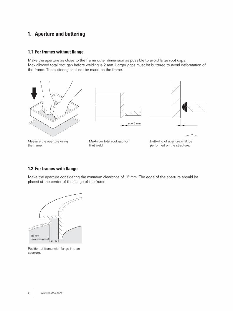
1. Aperture and buttering
1.1 For frames without fl ange
Make the aperture as close to the frame outer dimension as possible to avoid large root gaps. Max allowed total root gap before welding is 2 mm. Larger gaps must be buttered to avoid deformation of the frame. The buttering shall not be made on the frame.
Measure the aperture using the frame.
Maximum total root gap for fillet weld.
Buttering of aperture shall be performed on the structure.
max 2 mm
max 2 mm
1.2 For frames with fl ange
Make the aperture considering the minimum clearance of 15 mm. The edge of the aperture should be placed at the center of the flange of the frame.
Position of frame with flange into an aperture.
15 mm (min clearance)
5www.roxtec.com
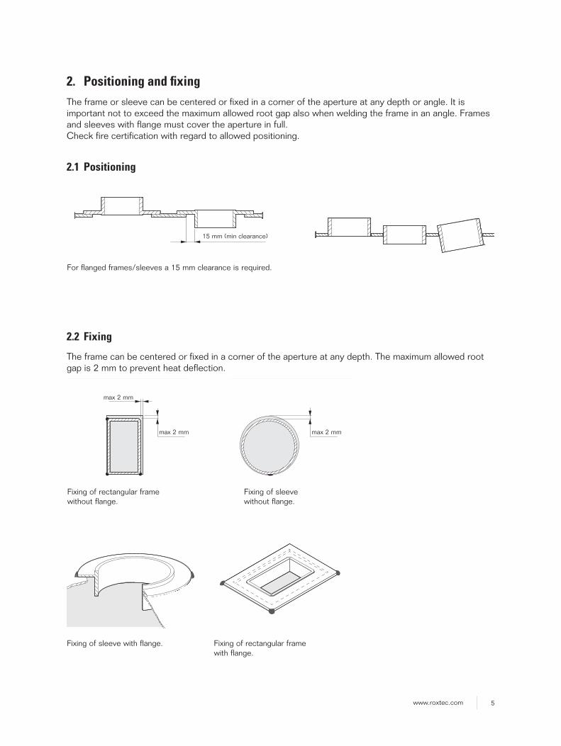
2. Positioning and fi xingThe frame or sleeve can be centered or fixed in a corner of the aperture at any depth or angle. It is important not to exceed the maximum allowed root gap also when welding the frame in an angle. Frames and sleeves with flange must cover the aperture in full. Check fire certification with regard to allowed positioning.
2.1 Positioning
2.2 Fixing
The frame can be centered or fixed in a corner of the aperture at any depth. The maximum allowed root gap is 2 mm to prevent heat deflection.
For flanged frames/sleeves a 15 mm clearance is required.
Fixing of rectangular framewithout flange.
max 2 mm
max 2 mm max 2 mm
Fixing of sleevewithout flange.
15 mm (min clearance)
Fixing of sleeve with flange. Fixing of rectangular frame with flange.

6 www.roxtec.com
3. Tack weldApply tack welds with a length of 15-20 mm on the back side at the corners and in the center of every opening of the fl ange. Use an appropriate tool to clamp the frame in tolerance during the whole welding process to avoid heat defl ection. Do not remove the tool until the frame has a temperature below 50˚C. Clamping is only required at the side openings and in the center of a x3 combination frame. Note: If the fi llet weld is applied on only one side the tacking must be made on the opposite side.
Clamp tool applied on a rectangular frame without fl ange.
Tack welded rectangular frame without fl ange.
Tack weld of a rectangular combination frame without fl ange.
Tack weld of a sleeve with fl ange.
Tack weld of a rectangular combination frame with fl ange.
15-20mm
Tack weld of a sleeve without fl ange.

7www.roxtec.com
4. Fillet and seal weld
■ Apply the fillet weld on the front side with an interpass temperature below 150˚C for stainless steel and below 250˚C for mild steel or aluminum. The weld runs shall not exceed 150 mm/weld pass.
■ Grind off the tack welds on the back side before applying the optional seal weld.
Note: The optional seal weld is for corrosion protection only and not mandatory unless specifi ed by the design.
Weld sizes Max heat input (kJ/mm)
Frame thickness T1
Structure thicknessT2
Fillet weld size (max)
Seal weld size (max)
Mild steel Stainless steel Aluminum
5-6 3<T2<12 a3 (z4) a3 (z4) 1.5 1.1 2.5
10-12 ≤6 a4 (z5) a3 (z4) 1.5 1.1 2.5
10-12 >6 a5 (z7) a3 (z4) 1.5 1.1 2.5
Welding method Thermalefficiency
SMAW (shielded metal arc) 1.0
GMAW (gas metal arc) 0.8
GTAW (gas tungsten arc) 0.6
Q = k x U x I x 60v x 1000
Q = Heat input [KJ/mm]U = Voltage [V] I = Current [A]v = Welding speed [mm/min]k = Thermal effi ciency [dimensionless]
Weld pass front
T2
T1
a
(z)
Seal weld back side if required by design
Weld pass front side
T2
T1
a
(z)
Seal weld back side if required by design
Frame/sleeve with fl ange.
Frame/sleeve without fl ange.
8 www.roxtec.com
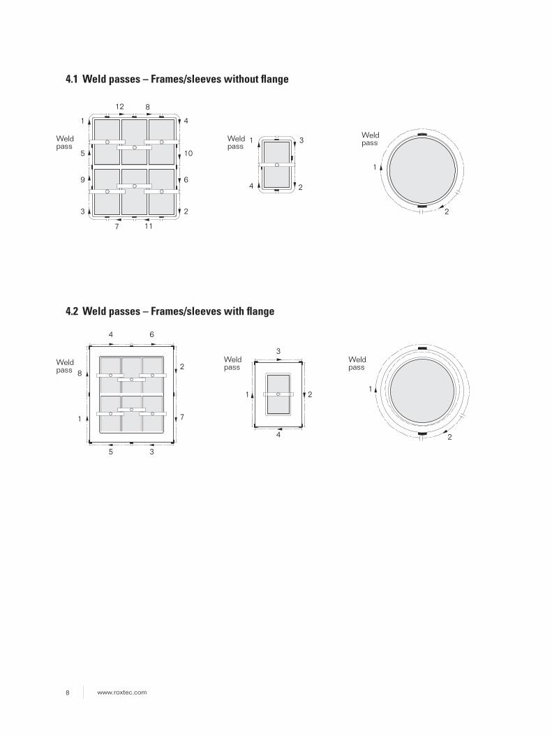
4.1 Weld passes – Frames/sleeves without fl ange
4.2 Weld passes – Frames/sleeves with fl ange
1
1
8
1
1
4
4 6
4
4
12
Weld pass
Weld pass
Weld pass
Weld pass
117
8
5 10
9 6
3
3
3
2
1
Weld pass
2
1
Weld pass
2
2
7
5 3
2
2
9www.roxtec.com
W +1 -0.5
+B ØD -C
H ±1
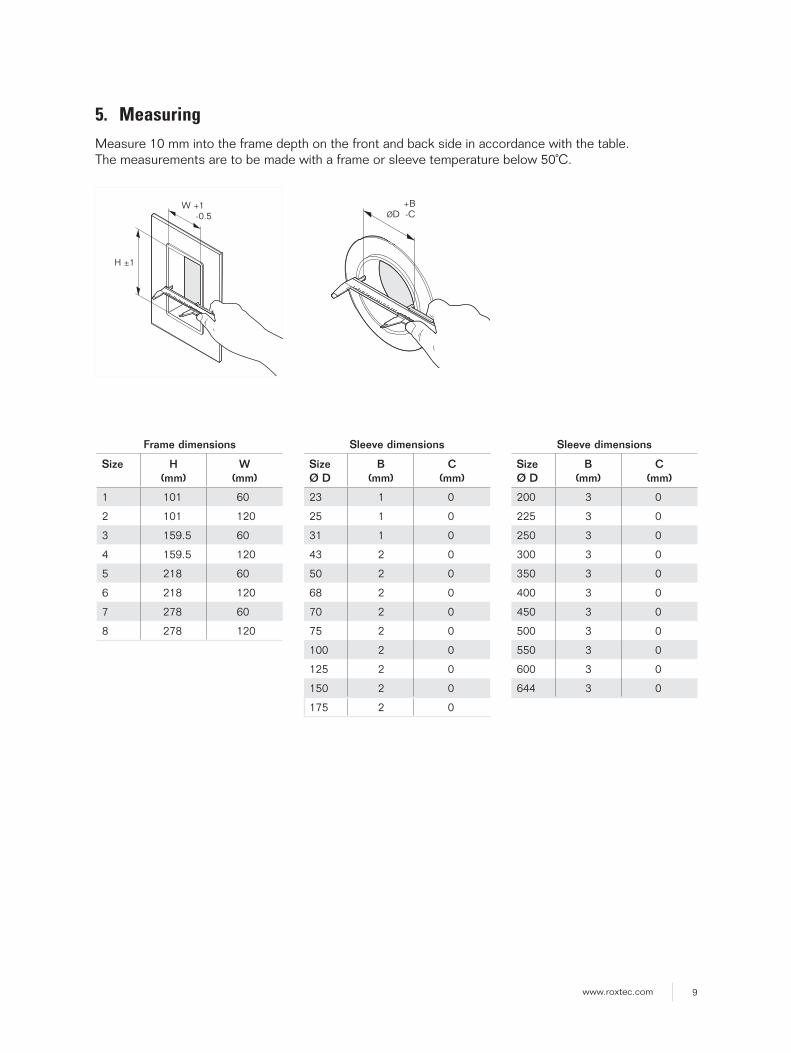
5. MeasuringMeasure 10 mm into the frame depth on the front and back side in accordance with the table. The measurements are to be made with a frame or sleeve temperature below 50˚C.
Frame dimensions
Size H(mm)
W(mm)
1 101 60
2 101 120
3 159.5 60
4 159.5 120
5 218 60
6 218 120
7 278 60
8 278 120
Sleeve dimensions
SizeØ D
B(mm)
C(mm)
23 1 0
25 1 0
31 1 0
43 2 0
50 2 0
68 2 0
70 2 0
75 2 0
100 2 0
125 2 0
150 2 0
175 2 0
Sleeve dimensions
SizeØ D
B(mm)
C(mm)
200 3 0
225 3 0
250 3 0
300 3 0
350 3 0
400 3 0
450 3 0
500 3 0
550 3 0
600 3 0
644 3 0

10 www.roxtec.com
H ±
1
W1 +1-0.5(1
0)
(10) (10)
6.1 SO frames
Weld the frame parts together before fixing it to the structure. Make sure to keep the geometrical tolerances. After assembly the SO frame is welded following the normal routine for a rectangular frame without flange with fixing, buttering and fillet weld. See table on page 7 for appropriate heat input.
6.2 Dimensions after welding
SO frame opening
Size H1(mm)
W1(mm)
1x1 101 60
2x1 101 120
3x1 159.5 60
4x1 159.5 120
5x1 218 60
6x1 218 120
7x1 278 60
8x1 278 120
6. SO, Openable framesOpenable frames intended for retrofit are recommended to be installed by welders qualified according to the latest edition of AWS D1.1, ISO 9606-1 2013, ISO 9606-2 2004 or other authorized system. It is important to achieve a gas-tight weld and secure that the burn through is well controlled preferably by backing.
Grind off the fi xing welds. Remove frame part. Protect cables during welding.
H ±
1
W1 +1-0.5
(10)
(10)
Note 1
Note 1: Min 20% burn through of total weld length. Max R1 on all inner corners.
Note 1
Note 1
11www.roxtec.com
H ±
1
(3)
W1 +1-0.5
A
Note 1
A
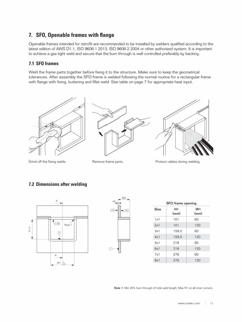
7.1 SFO frames
Weld the frame parts together before fixing it to the structure. Make sure to keep the geometrical tolerances. After assembly the SFO frame is welded following the normal routine for a rectangular frame with flange with fixing, buttering and fillet weld. See table on page 7 for appropriate heat input.
7. SFO, Openable frames with fl angeOpenable frames intended for retrofit are recommended to be installed by welders qualified according to the latest edition of AWS D1.1, ISO 9606-1 2013, ISO 9606-2 2004 or other authorized system. It is important to achieve a gas-tight weld and secure that the burn through is well controlled preferably by backing.
7.2 Dimensions after welding
SFO frame opening
Size H1(mm)
W1(mm)
1x1 101 60
2x1 101 120
3x1 159.5 60
4x1 159.5 120
5x1 218 60
6x1 218 120
7x1 278 60
8x1 278 120
(60)
Grind off the fi xing welds. Remove frame parts. Protect cables during welding.
Note 1: Min 20% burn through of total weld length. Max R1 on all inner corners.

12 www.roxtec.com
7.3 Procedure – single frame
Note 1
(2x)
Note 1: Min 20% burn through of total weld length. Max R1 on all inner corners.
13www.roxtec.com
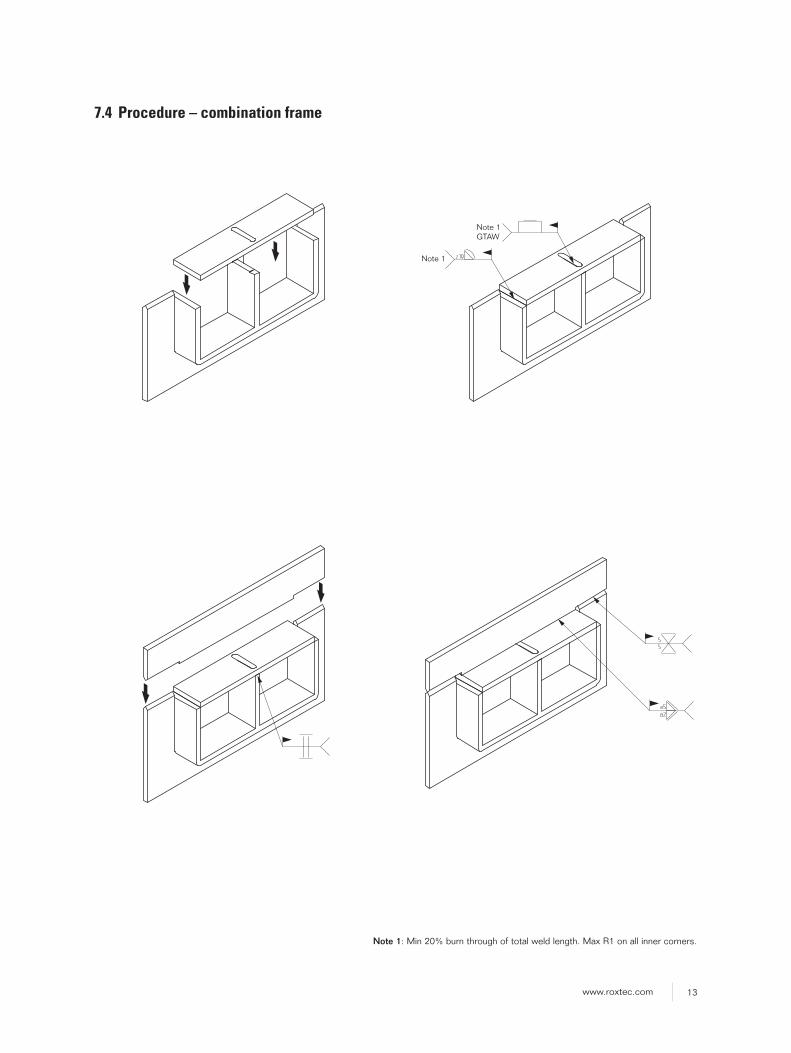
7.4 Procedure – combination frame
Note 1GTAW
Note 1
Note 1: Min 20% burn through of total weld length. Max R1 on all inner corners.

14 www.roxtec.com
8. Caution!Even though the guideline is an help to make safe welds it is important to be aware of potential errors that can lead to system failure. Below sections are examples of errors that can occur during welding.
8.1 Intermittent welds
Make sure to overlap weld seams.
8.3 Weld pass
Start a new weld seam from an end point of a previous weld.
8.2 Exceeding the recommended weld size
Excessive welding or too large heat input can cause the frame to deflect and thereby increase the packing space, lowering the compression in the sealing system.
End point of previous weld
Start point of previous weld
Start point for new weld
Welddirection

15www.roxtec.com
16 www.roxtec.com
Roxtec ®
and Multidiam
eter ® are registered tradem
arks of Roxtec in S
weden and/or other countries.
Roxtec International AB Box 540, 371 23 Karlskrona, SWEDEN PHONE +46 455 36 67 00, FAX +46 455 820 12 EMAIL [email protected], www.roxtec.com
PD
F2016000301 ver_1.0/EN
/1604/stsan
DISCLAIMER”The Roxtec cable entry sealing system (”the Roxtec system”) is a modular-based system of sealing products consisting of different components. Each and every one of the components is necessary for the best performance of the Roxtec system. The Roxtec system has been certifi ed to resist a number of different hazards. Any such certifi cation, and the ability of the Roxtec system to resist such hazards, is dependent on all components that are installed as a part of the Roxtec system. Thus, the certifi cation is not valid and does not apply unless all components installed as part of the Roxtec system are manufactured by or under license from Roxtec (“authorized manufacturer”). Roxtec gives no performance guarantee with respect to the Roxtec system, unless (I) all components installed as part of the Roxtec system are manufactured by an authorized manufacturer and (II) the purchaser is in compliance with (a), and (b), below.
(a) During storage, the Roxtec system or part thereof, shall be kept indoors in its original packaging at room temperature.
(b) Installation shall be carried out in accordance with Roxtec installation instructions in effect from time to time.
The product information provided by Roxtec does not release the purchaser of the Roxtec system, or part thereof, from the obligation to independently determine the suitability of the products for the intended process, instal-lation and/or use. Roxtec gives no guarantee for the Roxtec system or any part thereof and assumes no liability for any loss or damage whatso-ever, whether direct, indirect, consequential, loss of profi t or otherwise, occurred or caused by the Roxtec systems or installations containing components not manufactured by an authorized manufacturer and/or occurred or caused by the use of the Roxtec system in a manner or for an application other than for which the Roxtec system was designed or intended. Roxtec expressly excludes any implied warranties of merchan-tability and fi tness for a particular purpose and all other express or implied representations and warranties provided by statute or common law. User determines suitability of the Roxtec system for intended use and assumes all risk and liability in connection therewith. In no event shall Roxtec be liable for indirect, consequential, punitive, special, exemplary or incidental damages or losses.”


![BS EN ISO 9606-2_2004[1]](https://static.fdocuments.us/doc/165x107/552d83154a795956618b46a9/bs-en-iso-9606-220041.jpg)