Routing - shopsmith.com The drill press mode of the Mark ... • When workpiece edge is 1" to 2-3/4"...
9
Routing The drill press mode of the Mark V can be used as a stationary router in both its vertical and horizontal positions. But to accomplish this, a special chuck is required to secure the high-speed bits because of the side thrust that is characteristic of routing opera- tions. The chuck is locked firmly in place by securing its setscrew against the main spindle's tapered flat. Two setscrews lock the bits in the chuck. Router bits can be straight or, like the dovetail cutter, may have shaped cutting edges. The routing accessories are shown in Figure 10-1. Routing cuts are made at high speed and with reasonable feed pressure so the bit can do its job without choking or burning. Always perform routing opera- tions at “Fast” speed. Do not form excessively deep cuts in a single pass. Deep cuts are easier to make and the results will be smoother if you get to full depth of cut by making repeat passes no deeper than 1/ 4" or less, depending on the size of the bit. ROUTING SAFETY Warning: Before using the routing accessory, read and understand these Important safety instruc- tions: Danger Zone—The danger zone on the Mark V when routing extends 3" all around the bit and chuck and 5" in front of the bit. Always keep your fingers and hands out of the danger zone. When you work at the router, pay attention to where you put your hands. Be certain they aren't in front of the bit when you advance the quill. Never reach in toward or in front of the bit to clear away scraps. Turn off the machine and let it come to a complete stop first. Guard for the Router—The circular shield and brush assembly must always be used for router opera- tions. It mounts to the quill and is adjustable to accommodate various thicknesses of stock. • Wear proper eye and ear protection. • Tuck long hair under a hat or tie It up. Do not wear ties, gloves, jewelry or loose clothing. Roll sleeves up above your elbows. Wear non-slip footwear. • Always mount the circular shield and brush assembly on the Mark V quill before performing routing operations. • Always run the router at ‘FAST’ speed. • Avoid taking deep cuts. With the exception of single-pass dovetail cuts, limit depth of cut to 1/4" for each pass when using bits up to 1/2" dIameter. When using bits over 1/2" diameter, limit depth of cut to 1/8". Figure 10-1. The accessories that are used for routing are: (A) the circular shield and brush assembly, (B) router chuck, and (C) router bits. Also the rip fence and miter gauge are used to support and guide the stock.
Transcript of Routing - shopsmith.com The drill press mode of the Mark ... • When workpiece edge is 1" to 2-3/4"...

Routing
The drill press mode of the MarkV can be used as a stationaryrouter in both its vertical andhorizontal positions. But toaccomplish this, a special chuck isrequired to secure the high-speedbits because of the side thrust thatis characteristic of routing opera-tions. The chuck is locked firmlyin place by securing its setscrewagainst the main spindle's taperedflat. Two setscrews lock the bitsin the chuck. Router bits can bestraight or, like the dovetailcutter, may have shaped cuttingedges. The routing accessoriesare shown in Figure 10-1.Routing cuts are made at highspeed and with reasonable feedpressure so the bit can do its jobwithout choking or burning.Always perform routing opera-tions at “Fast” speed. Do not form excessively deep cuts in a single pass. Deep cuts are easier to makeand the results will be smoother if you get to full depth of cut by making repeat passes no deeper than 1/4" or less, depending on the size of the bit.
ROUTING SAFETYWarning: Before using the routing accessory, read and understand these Important safety instruc-tions:Danger Zone—The danger zone on the Mark V when routing extends 3" all around the bit and chuckand 5" in front of the bit. Always keep your fingers and hands out of the danger zone.When you work at the router, pay attention to where you put your hands. Be certain they aren't in frontof the bit when you advance the quill. Never reach in toward or in front of the bit to clear away scraps.Turn off the machine and let it come to a complete stop first.Guard for the Router—The circular shield and brush assembly must always be used for router opera-tions. It mounts to the quill and is adjustable to accommodate various thicknesses of stock.
• Wear proper eye and ear protection.• Tuck long hair under a hat or tie It up. Do not wear ties, gloves, jewelry or loose clothing. Roll
sleeves up above your elbows. Wear non-slip footwear.• Always mount the circular shield and brush assembly on the Mark V quill before performing
routing operations.• Always run the router at ‘FAST’ speed.• Avoid taking deep cuts. With the exception of single-pass dovetail cuts, limit depth of cut to 1/4"
for each pass when using bits up to 1/2" dIameter. When using bits over 1/2" diameter, limit depthof cut to 1/8".
Figure 10-1. The accessories that are used for routing are: (A) the circular shieldand brush assembly, (B) router chuck, and (C) router bits. Also the rip fence andmiter gauge are used to support and guide the stock.
• Never freehand rout. Always use the rip fence or mitergauge when using bits without pilots, and a starter pinwhen using bits with pilots.
• Always feed the workpiece against the rotation of the bit.Otherwise a kickback will occur.
• Feed the workpiece slowly. Use extra care when routingstock that contains figured grain or knots, as these maycause kickbacks.
• Use a push stick to feed a narrow workpiece. When it Isnecessary to push a workpiece underneath the shield, use along piece of scrap wood.
• Cut with the grain when straight-line routing.• Do not stand directly inline with the workpiece. in the
event of a kickback you could be hit.• When routing across the grain of workpieces up to 10"
wide, always use your miter gauge with safety grip tocontrol the workpiece.
• When stop routing, always use stop block(s) to control thelength of cut. Failure to use stop block(s) will cause akickback.
• When routing an oversize workpiece, always use at leastone push block to help control the workpiece. Hold theworkpiece firmly against the rip fence.
• When edge routing with a piloted bit, always use either astarter pin or a fence to start the cut and/or guide theworkpiece.
• Set speed to ‘SLOW,’ turn off and unplug the Mark Vbefore mounting router bits.
• Make sure the setscrew in the chuck is tightened againstthe fiat of the main spindle and the bit is secured tightly inthe chuck. Then remove the Allen wrench immediately.
• Listen for chatter or signs of looseness at startup. If youhear, see or suspect problems, turn off and unplug themachine. Correct any problem before proceeding.
• Keep the bits clean, maintained and sharp.
ROUTER BITSRouter bits come in a variety of shapes and sizes, each designedto perform a specific operation. You'll also find how to use deco-rative edging bits and how to perform additional routing opera-tions.
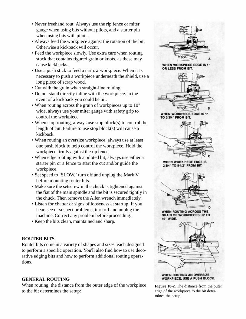
GENERAL ROUTINGWhen routing, the distance from the outer edge of the workpieceto the bit determines the setup:
Figure 10-2. The distance from the outeredge of the workpiece to the bit deter-mines the setup.

• When workpiece edge is 1" or less from bit, use one feather board on the infeed side and anadditional feather board on the outfeed side, both secured in the table slot. Use a push stick, orwhen it's necessary to push work-piece underneath the shield, use a piece of wood (Figure 10-2A).
• When workpiece edge is 1" to 2-3/4" from bit, use two feather boards as above or use one featherboard centered to the bit, secured in table slot. Use a push stick or piece of wood to push theworkpiece under the shield (Figure 10-2B).
• When workpiece edge is 2-3/4" to 5-1/2" from bit, use one feather board centered to the bit andse-cured to table with two C-clamps. Use a push biock (Figure 10-2C).
• When routing across the grain of workpieces upto 10" wide, use the miter gauge and safety grip.Workpiece must extend 5-1/2" away from bit (Figure 10-2D).
• When routing an oversizeworkpiece, use a push block(Figure 10-2E).
Router cuts made with the grainare smoother than cross grain oragainst the grain cuts, but youcan't always work that way. Whenyou can't, work with a slowerfeed rate and less depth of cutforop-timum results.The depth of single pass cutsshould be limited as follows:• 1/4" maximum depth of cut forbits upto 1/2" diameter.• 1/8" maximum depth of cut forbits over 1/2" diameter.• Less than the above limits whenrouting extremely hard wood.
Feed the workpiece from left toright against the bit's direction ofrotation (Figure 10-3). The actionof the properly installed bit willhelp keep the workpiece againstthe fence.When using auxiliary facings, it isa good idea to remember thatwhen the fence is behind the bit,the pass is also made from left toright.
Make cross grain cuts by workingwith the miter gauge and safetygrip (Figure 10-4). Some chippingwill occur where the bit breaksthrough, so allow for it by making
Figure 10-3. Feed teh workpiece from left to right agains the bit’s direction ofrotation. A slow feed with a shallow depth of cut will produce the best results.
Figure 10-4. Make cross grain cuts by working with the miter gauge and safetygrip.

the cut on an extra-wide piece. Then you can remove the chippededge using the table saw or jointer.
Stock edges are often routed to form rabbets. For this and similarkinds of work, make an auxiliary facing, as shown in Figure 10-5,that can be attached to the rip fence as shown in Figure 10-6. Therelief area allows adjustments so the bit can project beyond thebearing surface of the facing. The depth of cut is controlled byquill extension; width of cut is controlled by how much the bit pro-jects. If you need a wider cut, move the table or reposition thefence and make another pass.
MORTISESMortises with round ends can beformed with a router bit (Figure10-7). Mark the stock where themortise begins; clamp stop blocksto a fence extension to control thelength of the mortise in bothdirections. Position the workpieceagainst the left stop block so thebit will be at the first mark, extendthe quill to penetrate theworkpiece, and lock it. Then movethe workpiece until it contacts theright stop block. Mortise cuts areusually quite deep, so repeatpasses will be necessary. Thewidth of the mortise depends onthe size of the bit.
Figure 10-5. Constructiondetails of the auxiliary facing.
Figure 10-6. An auxiliary facing that can be bolted to the rip fence is amust for many routing operations. The relief area allows for setting the bitso cuts like the rabbet can be made.
Figure 10-7. The stop blocks determine the length of the mortise. Full mortisedepth is reached by making repeat passes.
Figure 10-8. Mortises formed with arouter bit will have round ends, so thetenon must be shaped to fit.

Mortises formed this way will have round ends; therefore, the tenon mustbe shaped to fit (Figure 10-8).
Slots—Slots are formed the same way as mortises except that after thequill is extended and locked in position, the cut starts at the end of theworkpiece and continues until it contacts the stop block (Figure 10-9).
DOVETAILSA dovetail is one of the strongestjoints in woodworking because itwill resist a pulling strain in everydirection but the one from whichthe tenons are inserted into theslots. Two common applicationsare shown in Figure 10-10.
The same dovetail cutter is used toform both the tenon and the slot.Mating the parts is a matter ofpositioning the cuts in properrelationship to each other.
Spacing of the cuts is determinedby the size of the cutter and thedesign of the joint. One method isto mark the workpiece and aligneach cut with the cutter. Anothermethod is to pencil mark theworktable so that the edge of theworkpiece can be moved forward to a new mark after each cut. When you mark the worktable, first
Figure 10-9. Slots are formed like mortises except that the cut starts at the endof the workpiece.
Figure 10-10. These aretypical examples of dovetailjoints.
Figure 10-11. Dovetail tenons can be formed as shown. The table height lever(Model 500) or table height crank (Model 510) is used as the forward feedmechanism.

deter-mine the centerline of thespindle; then mark the cutlines bymeasuring toward the worktableedges, front and rear. One techniqueis to use measuring tape which has agummed side. This may be placedon the worktable and then removedwhen not in use.
To cut dovetail tenons as shown inFigure 10-11, position the work-table parallel to the way tubes. Usethe table height lever (Model 500)or table height crank (Model 510)as a forward feed mechanism, thestop collars from the lathe tailstockto control table movement, the quillfeed lever to obtain exact depth ofcut, the rip fence as a platform forthe workpiece and the miter gaugeto square the work-piece to thecutter. When feeding the workpieceforward against the cutter, move theworktable slowly, and be sure theworkpiece is clamped securely inplace. After the cut is made, turn offthe Mark V and return the work-table to the starting position. Ifdesired, place the workpiece for thenext cut and repeat the procedure.
The mating cuts are formed withthe worktable in the horizontalposition and with the fence used asa guide (Figure 10-12). The table isbrought up as close to the cutter aspossible, and the final adjustment ismade by extending the quill. Theworkpiece is fed forward againstthe cutter. A stop is clamped on thefence to control the length of cut.For spacing, the fence can bemoved for each new cut or theworktable can be advanced-again byusing the table height mechanism asa forward feed device. Whenfeeding the workpiece against thecutter, hold it firmly on the work-
Figure 10-12. Make dovetail slots using a feather board and push block.
Figure 10-13. This long dovetail slot might be required for a sliding assembly.Note the position of the worktable and the rip fence and the use of the featherboard and fence extension.

table and push it slowly. Caution: Ifthe cut is for a through dovetail,use a scrap block between thework and the table.
The tenon on a single, wide dove-tail is formed by making two cuts,one on each end of the stock. Themating part is formed the sameway, with the waste stock cut awayby running the work across thecutter within limits set by the twoend cuts and stop blocks. Caremust be exercised in positioningthe pieces for successive cuts, buttesting in scrap wood beforecutting will make this easier. Byusing the setups shown in Figures10-13 and 10-14, you can joinboards edge-to-edge or provide asliding arrangement.
Cut the slot in one pass by placingthe table as shown and adjustingitso the cut is made directly downthe centerline of the board (Figure10-13). Depth of cut is set bylowering the quill and locking it inposition. Feed the workpieceslowly and keep it flat against thetable. Don't force the workpiece.
The tenon requires two passes. Theworkpiece is positioned so thecutter forms the tenon on one sideof the board. Then the workpiece isturned and the second pass ismade; thus, the cutter completesthe forming of the tenon on theopposite surface of the board(Figure 10-14). Here, even morethan elsewhere, be sure theworkpiece is held firmly and flatagainst the table. Constructiondetails for the fence extension areshown in Figure 5-10.
Figure 10-14. A dovetail tenon is formed in two passes, one on each face of thestock.
Figure 10-15. A sliding table greatly simplifies cutting a dovetail slot in anextrawide piece.

Wide stock that must be grooved across the grain requires a sliding table arrangement to which the workcan be clamped (Figure 10-15). The fixture is constructed as shown in Figure 10-16, with the runnerssituated so the platform will slide smoothly on the table. The table is raised to an approximate positionand the final adjustment for depth of cut is made by using the quill feed lever.
With this arrangement the length of cut is limited to the distance from the cutter to the tubes. On narrowstock the groove can be completed in one pass by using a spacer board between the workpiece and thefence. Wide boards require two cuts from opposite sides of the board on a common centerline. Alignmentis important. Locate the cutter center by marking a pencil line on the fence of the sliding table. Mark lineson the workpiece to locate the centerlines of the grooves. Align these with the mark on the fence. Sincethe first half-cut (on wide boards) removes the line, it is necessary to use a straightedge to realign theworkpiece with the mark on the fence before completing the cut (Figure 10-17). This method is notlimited to dovetail grooves; straight grooves are cut with router bits, and the procedure is exactly thesame.
HORIZONTAL ROUTINGAs shown in Figure 10-18, grooves are cut with the Mark V in the horizontal position. A fence ex-tensionand feather board provide guidance and support as the workpiece is fed through. Construction details forthe fence extension are found in Figure 5-10.
The depth of cuts given in “General Routing” apply. If it's tough to feed the workpiece, the workpiecechatters, or the cut is rough, you are probably cutting too deep. Back off and make repeat passes instead.The same setup can be used to form rabbets or tongues.
Figure 10-16. Construction details of the sliding table. Runners should fit snuglyagainst the edges of the table (Model 500) or the table tubes (Model 510).
Figure 10-17. Two passes areneeded on an extra-wideworkpiece. Be sure to align thebith with the kerf.

Handle cross grain cuts by work-ing with the miter gauge andusing the miter gauge stop rod todetermine the depth of cut (Fig-ure 10-19). There will be somefeathering at the end of the cut,so work on a piece that is widerthan you need. Remove the chipby making a light jointer cut or bysawing.
Figure 10-18. A router bit can be used to form edge grooves if this setup isemployed. The feather board keeps the workpiece flat on the table.
Figure 10-19. Use the miter gauge and miter gauge stop rod when doing crossgrain work. Feathering at the end of the cut is characteristic but is easilyremoved by jointing or sawing.