ROUTER JIG EXTREME™ AR-15 AR-10 AR-9 Jig Manual V1.31 8.5x1… · D) Router Adapter Plate E)...
16
USER GUIDE v1.31 ROUTER JIG EXTREME™ AR-15 AR-10 AR-9
Transcript of ROUTER JIG EXTREME™ AR-15 AR-10 AR-9 Jig Manual V1.31 8.5x1… · D) Router Adapter Plate E)...

USER GUIDE v1.31
ROUTER JIG EXTREME™ AR-15 AR-10 AR-9
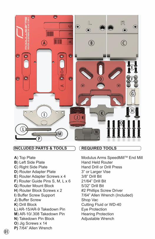
INCLUDED PARTS & TOOLS
A) Top PlateB) Left Side PlateC) Right Side PlateD) Router Adapter PlateE) Router Adapter Screws x 4F) Router Guide Pins S, M, L x 6G) Router Mount BlockH) Router Block Screws x 2I) Buffer Screw SupportJ) Buffer ScrewK) Drill BlockL) AR-15/AR-9 Takedown PinM) AR-10/.308 Takedown PinN) Takedown Pin BlockO) Jig Screws x 14P) 7/64” Allen Wrench
REQUIRED TOOLS
Modulus Arms SpeedMillTM End MillHand Held RouterHand Drill or Drill Press3” or Larger Vise3/8” Drill Bit21/64” Drill Bit5/32” Drill Bit#2 Phillips Screw Driver7/64” Allen Wrench (Included)Shop VacCutting Fluid or WD-40Eye ProtectionHearing ProtectionAdjustable Wrench
A B C
D
E
F
G
I JK H
L
PM N
O
0!

A1 Loosely thread the Takedown Pin Block to the Top Plate. Note that the larger .308/AR-10 pin holes should stick out past the front of the top plate.
A2 Align the Buffer Screw Support to the lower receiver as shown.
A3 Loosely thread the Buffer Screw through the Buffer Screw Support into the lower receiver.
A4 Align lower receiver takedown pin holes with the Takedown Pin Block holes and slide the lower receiver up into the jig. Insert the correct takedown pin through the lower receiver and Takedown Pin Block holes. For AR-15/AR-9 use the back-most holes. For .308/AR-10 use the front-most holes.
A5 Use 2 Jig Screws to tighten the Buffer Screw Support to the jig. For AR-15/AR-9 use the innermost holes on the support and the furthest forward holes on the jig. For .308/AR-10 use the outermost holes on the support and the furthest back holes on the jig.
The Modulus Arms Router Jig Extreme™ is the most durable, cost effective, easy to use, and fastest jig on the market to effortlessly finish your 80% lowers. Our products represent the best value and quality for your money. Please read this manual from start to finish before starting your build, paying careful attention to all warnings and notices in the manual. We’re here to help you at [email protected] if you have any questions, require assistance, or need replacement parts.
A - JIG ASSEMBLY
AR-15
AR-10
0@

A6 Align and tightly secure the right and left Side Plates to the Jig Top Plate using 8 of the Jig Screws.
A7 Attach the Drill Block to the Top Plate using 2 Jig Screws. Securely tighten the screws.
A8 Tighten the Buffer Screw by passing a screw driver through the holes on the Buffer Screw and rotating clockwise. Do not use excessive force. Periodically tighten between milling passes.
A9 Secure the jig assembly into a vise clamping ONLY against the front and back edges of the side plates as shown in images. NEVER CLAMP THE VISE TO THE SIDE FACES OF THE SIDE PLATES OR YOU WILL DAMAGE THE JIG.
B - DRILLING PILOT HOLE
B1 Put on safety glasses. Apply ample cutting fluid or WD-40 into the Drill Block hole and fully insert the 21/64” drill bit until it touches the lower receiver. Holding the drill very straight, start drilling. Use a slow to medium drill speed setting. Fast speed will quickly overheat and dull the drill bit. Lift the drill bit out of the Drill Block several times while drilling to clear chips. Drill until the bit passes through the floor of the lower receiver.
0#
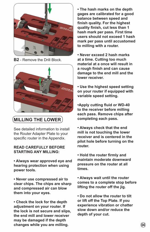
B2 - Remove the Drill Block.
MILLING THE LOWER
See detailed information to install the Router Adapter Plate to your specific router in the Appendix.
READ CAREFULLY BEFORE STARTING ANY MILLING:
• Always wear approved eye and hearing protection when using power tools.
• Never use compressed air to clear chips. The chips are sharp and compressed air can blow them into your eyes.
• Check the lock for the depth adjustment on your router. If the lock is not secure and slips, the end mill and lower receiver may be damaged if the depth changes while you are milling.
• The hash marks on the depth gages are calibrated for a good balance between speed and finish quality. For the highest quality finish, cut less than 1 hash mark per pass. First time users should not exceed 1 hash mark per pass until accustomed to milling with a router.
• Never exceed 2 hash marks at a time. Cutting too much material at a once will result in a rough finish and can cause damage to the end mill and the lower receiver.
• Use the highest speed setting on your router if equipped with variable speed setting.
•Apply cutting fluid or WD-40 to the receiver before milling each pass. Remove chips after completing each pass.
• Always check that the end mill is not touching the lower receiver and is centered in the pilot hole before turning on the router.
• Hold the router firmly and maintain moderate downward pressure on the router at all times.
• Always wait until the router comes to a complete stop before lifting the router off the jig.
• Do not allow the router to tilt or lift off the Top Plate. If you experience vibration or chatter slow down and/or reduce the depth of your cut.
0$

• Milling should be done by moving the router in slow, small, clockwise circles. Do not mill in straight lines until after the center area is milled out using circular motions. Then mill the edges by following the contour of the guide template.
C - MILLING TEMPLATE A
C1 Screw two Short Guide Pins into the Router Adapter Plate using the provided 7/64” Allen wrench. Do not over tighten the Guide Pins.
C2 While holding the base of the Router Adapter Plate against the edge of the Top Plate, set the depth of the end mill to the first hash mark of depth gauge “A” as shown in the image. Lock the depth adjustment on the router.
C3 Position the jig so the user is behind the Buffer Screw. Rest the router on the Top Plate with the end mill centered in the pilot hole. The cutout in the Router Adapter Plate should be facing the Buffer Screw. The small Guide Pins should be inside the recessed area of both templates.
C4 Mill the first hash mark pass and make sure to trace the full contour of the template.
0%

C5 While holding the base of the Router Adapter Plate against the edge of the Top Plate, set the depth of the end mill to the 2nd hash mark of depth gauge “A”. Lock the depth adjustment on the router. Mill the 2nd hash mark pass as you did the first one. Remember to use cutting fluid or WD-40.
C6 Increase depth by 1 hash mark and repeat milling process until all hash marks for depth gauge “A” have been milled. Adjust the depth of the end mill until the end mill bottoms out at the end of depth gauge “A” and mill the final pass for depth gauge “A”. DO NOT mill depth gauge “B” until the Short Guide Pins have been replaced with the Medium Guide Pins.
D - MILLING TEMPLATE B
D1 Remove the two Short Guide Pins and replace them with two Medium Guide Pins.
D2 Set depth of the end mill to the first hash mark of depth gauge “B” in the same manner as was done earlier for depth gauge “A”.
D3 Position the Router Adapter Plate so the Medium Guide Pins are in the recessed area for template “B” on both sides of the jig. Insert and center the end mill into the pilot hole and mill the first pass for depth gauge “B”. You may see a hole for the grip bolt which is normal. You should now only be milling template “B”, which is the main trigger pocket area, as shown in the following image.
0^
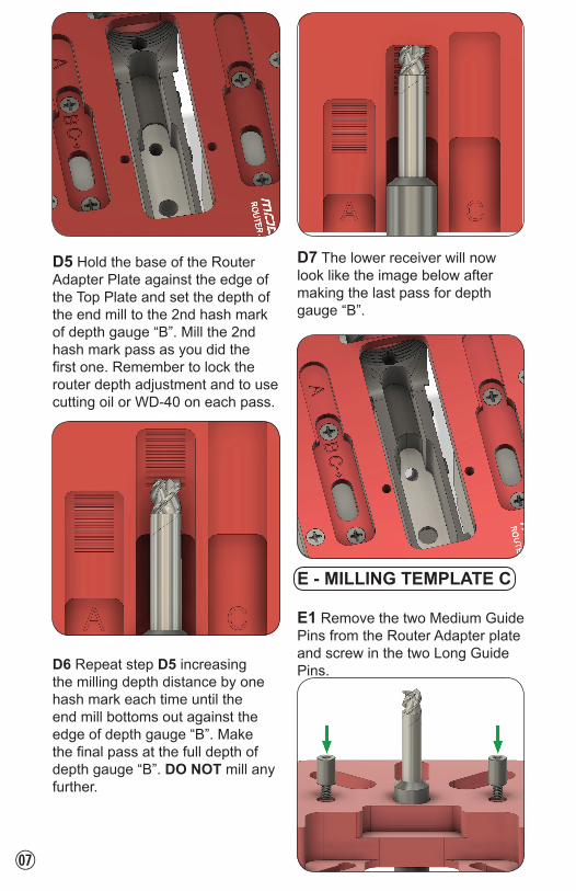
D5 Hold the base of the Router Adapter Plate against the edge of the Top Plate and set the depth of the end mill to the 2nd hash mark of depth gauge “B”. Mill the 2nd hash mark pass as you did the first one. Remember to lock the router depth adjustment and to use cutting oil or WD-40 on each pass.
D6 Repeat step D5 increasing the milling depth distance by one hash mark each time until the end mill bottoms out against the edge of depth gauge “B”. Make the final pass at the full depth of depth gauge “B”. DO NOT mill any further.
D7 The lower receiver will now look like the image below after making the last pass for depth gauge “B”.
E - MILLING TEMPLATE C
E1 Remove the two Medium Guide Pins from the Router Adapter plate and screw in the two Long Guide Pins.
0&
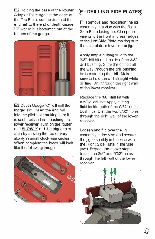
E2 Holding the base of the Router Adapter Plate against the edge of the Top Plate, set the depth of the end mill to the end of depth gauge “C” where it is bottomed out at the bottom of the gauge.
E3 Depth Gauge “C” will mill the trigger slot. Insert the end mill into the pilot hole making sure it is centered and not touching the lower receiver. Turn on the router and SLOWLY mill the trigger slot area by moving the router very slowly in small clockwise circles. When complete the lower will look like the following image.
F - DRILLING SIDE PLATES
F1 Remove and reposition the jig assembly in a vise with the Right Side Plate facing up. Clamp the vise onto the front and rear edges of the Left Side Plate making sure the side plate is level in the jig.
Apply ample cutting fluid to the 3/8” drill bit and inside of the 3/8” drill bushing. Slide the drill bit all the way through the drill bushing before starting the drill. Make sure to hold the drill straight while drilling. Drill through the right wall of the lower receiver.
Replace the 3/8” drill bit with a 5/32” drill bit. Apply cutting fluid inside both of the 5/32” drill bushings. Drill the two 5/32” holes through the right wall of the lower receiver.
Loosen and flip over the jig assembly in the vise and secure the jig assembly in the vice with the Right Side Plate in the vise jaws. Repeat the above steps to drill the 3/8” and 5/32” holes through the left wall of the lower receiver.
0*
G - DISASSEMBLY
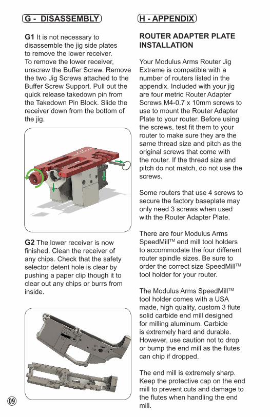
G1 It is not necessary to disassemble the jig side plates to remove the lower receiver. To remove the lower receiver, unscrew the Buffer Screw. Remove the two Jig Screws attached to the Buffer Screw Support. Pull out the quick release takedown pin from the Takedown Pin Block. Slide the receiver down from the bottom of the jig.
G2 The lower receiver is now finished. Clean the receiver of any chips. Check that the safety selector detent hole is clear by pushing a paper clip though it to clear out any chips or burrs from inside.
H - APPENDIX
ROUTER ADAPTER PLATE INSTALLATION
Your Modulus Arms Router Jig Extreme is compatible with a number of routers listed in the appendix. Included with your jig are four metric Router Adapter Screws M4-0.7 x 10mm screws to use to mount the Router Adapter Plate to your router. Before using the screws, test fit them to your router to make sure they are the same thread size and pitch as the original screws that come with the router. If the thread size and pitch do not match, do not use the screws.
Some routers that use 4 screws to secure the factory baseplate may only need 3 screws when used with the Router Adapter Plate.
There are four Modulus Arms SpeedMillTM end mill tool holders to accommodate the four different router spindle sizes. Be sure to order the correct size SpeedMillTM tool holder for your router.
The Modulus Arms SpeedMillTM tool holder comes with a USA made, high quality, custom 3 flute solid carbide end mill designed for milling aluminum. Carbide is extremely hard and durable. However, use caution not to drop or bump the end mill as the flutes can chip if dropped.
The end mill is extremely sharp. Keep the protective cap on the end mill to prevent cuts and damage to the flutes when handling the end mill.0(

ROUTER COMPATIBILITY CHARTROUTER INSTALL SpeedMillTM
MODEL METHOD SIZEBosch PR10EA _____ 2 ________ V1Bosch PR20EVA _____ 2 ________ V1Bosch 1617EVC _____ 3 ________ V4Bosch 1617EVSC _____ 3 ________ V4Craftsman 28212B _____ 1 ________ V2Craftsman 2767C _____ 3 ________ V4Craftsman 27683C _____ 3 ________ V4Craftsman 50429C _____ 3 ________ V4DeWalt DWE6000_____ 2 ________ V1DeWalt DWP611D _____ 1 ________ V2DeWalt DW616C _____ 3 ________ V4DeWalt DW618C _____ 3 ________ V4Hitachi M12VCC _____ 3 ________ V4Makita RT0701C _____ 2 ________ V3Porter Cable 450 _____ 1 ________ V2Porter Cable 6430 _____ 2 ________ V1Porter Cable 6435 _____ 2 ________ V1Rigid R24012A _____ 2 ________ V1A - Pull router base out additional distance to achieve the minimum cut depth.B - Only 3 screws are used to attach router.C - Requires purchase of Full Size Router Adapter PlateD - Recommended router of choice.
H1 Unplug the router and remove the factory plastic baseplate and base from the router to expose the collet and spindle. Remove the collet and make sure the spindle is clean and free of any burrs. Screw on the Modulus Arms SpeedMillTM end mill of the correct size for your router. Use a 5/8” wrench for size “A”, 11/16” for size “B”, 3/4” for size “C”, and 7/8” for size “D” to tighten the SpeedMillTM end mill tool holder to the router’s spindle. The original collet and collet nut are not used.
H2 Reinstall the factory base, but do not install the plastic baseplate.
H3 Slide the Router Adapter Plate over the end mill with the exposed side of the bearing facing the router.
H4 - Install Method # 1
Pass the thicker SpeedMillTM portion of the end mill holder through the bearing. This will align the router adapter plate with the spindle and end mill. Thread 4 Router Adapter Screws through the Router Adapter Plate to secure the plate to the router base. Tighten the screws being careful not to misalign the router adapter plate.
1)

H5 - Install Method # 2
For routers that only use 3 screws, the Router Mount Block will be used to secure the back screw to the router base.
Align the two screw holes in the front of the router base with the holes in the Router Adapter Plate and loosely thread the two screws through the Router Adapter Plate and into the router base.
Align and loosely mount the Router Mount Block to the back of the router using the router’s accessory mounting hole. Select the appropriate Router Block Screw that fits your router. Included with the jig is a metric M5-0.8 x 20mm and a M6-1.0 x 20mm screw, one of which fits most routers.
Loosely thread one Router Adapter Screw through the Router Adapter Plate and into the Router Mount Block. Tighten the two front Router Adapter Screws.
Press the Router Mount Block against the router and tighten the Router Mount Block screw. Next, tighten the Router Adapter Screw to the Router Mount Block.
H6 - Install Method # 3
This option is for larger routers that require the optional Full Size Router Plate Adapter.
Remove the factory baseplate from the router and place the Full Size Router Adapter Plate over the end mill with the countersunk screw cutouts facing away from the router. Use 3 of the screws you removed from the router’s baseplate to mount the Full Size Router Adapter Plate as shown in the following image.
H7 Attach the standard Router Adapter Plate to the Full Size Router Adapter Plate using 3 Router Adapter Plate Screws. Make sure the that the thicker portion of the SpeedMillTM end mill 1!

holder has passed into the bearing before tightening the 3 screws to ensure the end mill is aligned with the Router Adapter Plate.
TROUBLESHOOTING
The Modulus Arms Router Jig Extreme is extremely easy to use even for the novice user. In the unlikely event you experience any trouble using your jig, contact us at [email protected].
The Router Jig Extreme is capable of finishing lowers in minutes. Best results, however, are achieved by milling at a smooth and slow pace. The slower the milling, and the less material that is removed per pass, the finer the quality of the lower receiver will be. Near CNC mirror finish quality is possible with the Router Jig Extreme.
COATINGS
It is not necessary to apply a coating to the raw aluminum area after milling. However, if desired, options such as Cerakote and Duracoat are available to add a finish to the raw milled area.
WARRANTY
The Modulus Arms Router Jig Extreme™ carries a lifetime warranty valid for the original owner for manufacturing defects. To obtain warranty repairs, contact us at [email protected]. All returns must have a RMA number for the warranty claim to be processed.
LEGAL NOTICE
Check your local, state and federal laws before using this product. Some states may prohibit or restrict the use of this product to manufacture a firearm.
When in doubt, seek the advice of an attorney before manufacturing any firearm. Modulus Arms cannot provide legal advice.
IF YOU CAN’T LAWFULLY BUY OR POSSESS A FIREARM, IT IS ALSO ILLEGAL FOR YOU TO MANUFACTURE A FIREARM.
TIPS
To accurately set the end mill depth, be sure to hold the base of the Router Adapter Plate flush against the side of the Top Plate.
1@

1#
CLEAN UP
The Buffer Screw supplied with the jig will fit 1-1/4” Shop-Vac style hoses.
Connect a hose to the Buffer Screw and run the vacuum cleaner while milling to suction out and reduce the amount of cleanup and reduce cutting the chips in the lower.
To increase the effectiveness and amount of the suction, apply tape around the bottom area of the Top Plate and the lower receiver.

BLANK PAGE RESERVED FOR FUTURE USE
1$