ROUSH Throttle Body Electronic Fuel Injection Installation ... · Fuel Injection Installation and...
23
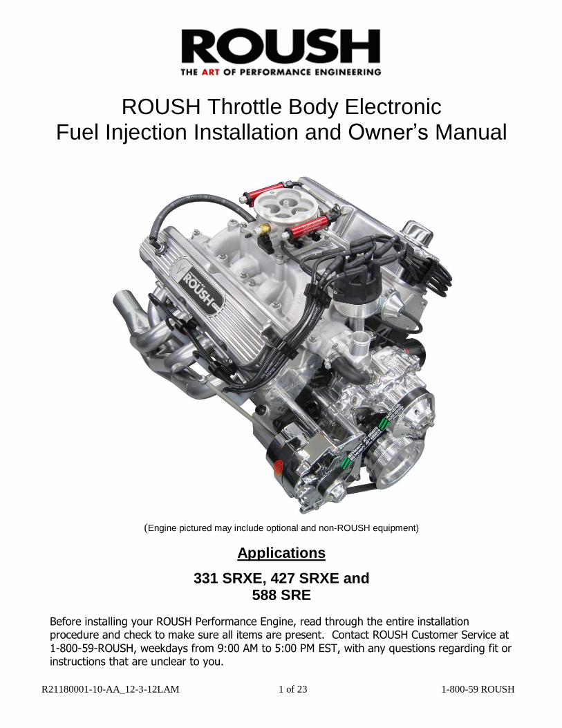
R21180001-10-AA_12-3-12LAM 1 of 23 1-800-59 ROUSH ROUSH Throttle Body Electronic Fuel Injection Installation and Owner’s Manual (Engine pictured may include optional and non-ROUSH equipment) Applications 331 SRXE, 427 SRXE and 588 SRE Before installing your ROUSH Performance Engine, read through the entire installation procedure and check to make sure all items are present. Contact ROUSH Customer Service at 1-800-59-ROUSH, weekdays from 9:00 AM to 5:00 PM EST, with any questions regarding fit or instructions that are unclear to you.
-
Upload
truonghanh -
Category
Documents
-
view
223 -
download
2
Transcript of ROUSH Throttle Body Electronic Fuel Injection Installation ... · Fuel Injection Installation and...
R21180001-10-AA_12-3-12LAM 1 of 23 1-800-59 ROUSH
ROUSH Throttle Body Electronic Fuel Injection Installation and Owner’s Manual
(Engine pictured may include optional and non-ROUSH equipment)
Applications
331 SRXE, 427 SRXE and 588 SRE
Before installing your ROUSH Performance Engine, read through the entire installation procedure and check to make sure all items are present. Contact ROUSH Customer Service at
1-800-59-ROUSH, weekdays from 9:00 AM to 5:00 PM EST, with any questions regarding fit or instructions that are unclear to you.

R21180001-10-AA_12-3-12LAM 2 of 23 1-800-59 ROUSH
LIMIT OF LIABILITY STATEMENT
The information contained in this publication was accurate and in effect at the time the
publication was approved for printing and is subject to change without notice or liability. ROUSH Performance Products (RPP) reserves the right to revise the information presented herein or to discontinue the production of parts described at any time.
SAFETY REQUIREMENTS
STOP! READ IMPORTANT SAFETY CAUTIONS AND WARNINGS BEFORE PROCEEDING.
IMPORTANT SAFETY NOTICE Appropriate disassembly/assembly methods and procedures are essential to ensure the personal
safety of the individual performing the kit installation. Improper installation due to the failure to correctly follow these instructions could cause personal injury or death. Read each step of the
installation manual carefully before starting the actual installation.
1. Always wear safety glasses for eye protection.
2. Place ignition switch in the OFF position.
3. Always apply the parking brake when working on a vehicle.
4. Block the front and rear tire surface to prevent unexpected vehicle movement.
5. If working without a lift, always consult vehicle manual for correct lifting specifications.
6. Operate the engine only in well-ventilated areas to avoid exposure to carbon monoxide.
7. Do not smoke or use flammable items near or around the fuel system.
8. Use chemicals and cleaners in well-ventilated areas.
9. Batteries produce explosive gases, which can cause personal injury. Therefore, do not allow flames, sparks or flammable substances to come near the battery.
10. Keeps hands and any other objects away from the radiator fan blades.
11. Keep yourself and your clothing away from moving parts when the engine is running.
12. Do not wear loose clothing or jewelry that can get caught in rotating parts or scratch surface finishes.
13. Allow the engine, cooling system, brakes and exhaust to cool before working on a vehicle.

R21180001-10-AA_12-3-12LAM 3 of 23 1-800-59 ROUSH
Engine Installation Requirements
Component Temperatures and Environments
All components of the ROUSH Engine Control System are designed to operate in environments between plus 20°F to 200°F. Care should be taken to insure that none of the components are subjected to heat sources that would exceed 200°F, excluding the UEGO sensors which are mounted to the exhaust system. System Components Overview
The EZ-EFI® system is made up of several main components: a throttle body, an ECU (Electronic Control Unit), a wiring harness, a hand-held user interface, several loose sensors and an RPM module. Please read through all of the installation notes before beginning the installation. Throttle Body
Throttle Body Installation Notes:
The throttle body will bolt on in place of a carburetor on an intake manifold with a 4150 square-flange. It uses a standard Holley-style throttle linkage. A ball stud and lock nut are included.
When installing the throttle body, it is good practice to replace the throttle body gasket.
There are three manifold vacuum ports on the base of the throttle body and one ported vacuum ports on the throttle body – near the air temperature sensor. Be sure to cap any unused vacuum ports.
A throttle return spring should be used.
An air cleaner should be used. The throttle body is compatible with standard carburetor air cleaners. Be sure to account for hood clearance issues when choosing an air cleaner.
There is some adjustability built into the linkage between the throttle shafts. It should be set up as close to a one-to-one arrangement as reasonably possible – as opposed to a progressive setup. Having all four blades open at the same time gives the best fuel distribution.
R21180001-10-AA_12-3-12LAM 4 of 23 1-800-59 ROUSH
*** IMPORTANT TECH BULLETIN***
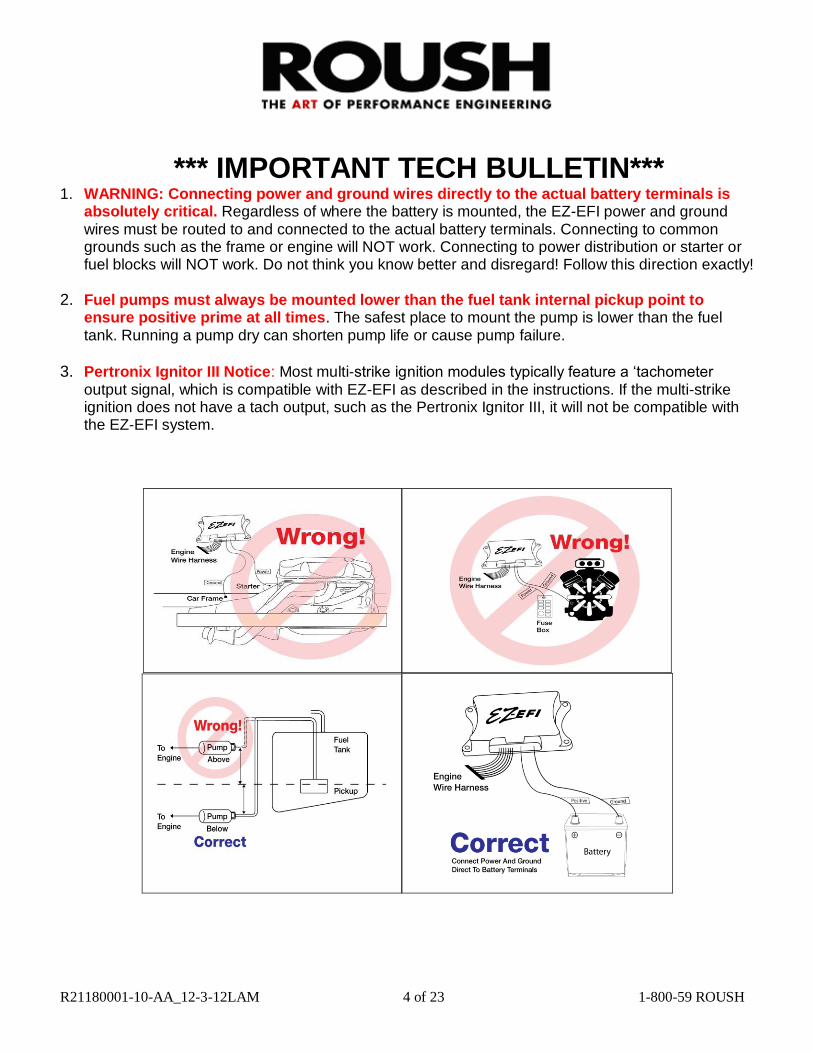
1. WARNING: Connecting power and ground wires directly to the actual battery terminals is absolutely critical. Regardless of where the battery is mounted, the EZ-EFI power and ground wires must be routed to and connected to the actual battery terminals. Connecting to common grounds such as the frame or engine will NOT work. Connecting to power distribution or starter or fuel blocks will NOT work. Do not think you know better and disregard! Follow this direction exactly!
2. Fuel pumps must always be mounted lower than the fuel tank internal pickup point to
ensure positive prime at all times. The safest place to mount the pump is lower than the fuel tank. Running a pump dry can shorten pump life or cause pump failure.
3. Pertronix Ignitor III Notice: Most multi-strike ignition modules typically feature a ‘tachometer
output signal, which is compatible with EZ-EFI as described in the instructions. If the multi-strike ignition does not have a tach output, such as the Pertronix Ignitor III, it will not be compatible with the EZ-EFI system.

R21180001-10-AA_12-3-12LAM 5 of 23 1-800-59 ROUSH
ECU (Electronic Control Unit)
ECU Installation Notes:
The ECU is water tight when connected to the wiring harness. It can be mounted in the engine compartment or in the vehicle’s interior. It is good practice to mount the ECU with the connector facing down. This way, there is less chance of moisture getting into the ECU if it needs to be disconnected in wet conditions.
The ECU should not be mounted close to other electrically “noisy” components. In particular, keep good spacing (try for 2 feet minimum) from ignition components (ignition boxes, coils, distributors, etc.).
If mounting in the engine compartment, selecting a location towards the rear will make it easier to route the communications cable to the interior to allow the hand-held to be monitored while driving. (After the initial setup, use of the hand-held is optional. It does not need to remain connected for the engine to run.) Optional, longer communications cables are available if needed.
There is an LED on the front face of the ECU – the side with the logo. It will flash if the onboard diagnostics detects a problem. (The LED will normally remain off at key-on and will then come on when the ECU detects an RPM input. It will be lit solid while the engine is running normally.) To take advantage of this feature, the ECU will need to be mounted so that the front face of the ECU is visible. The hand-held will also indicate if any faults have been detected.

R21180001-10-AA_12-3-12LAM 6 of 23 1-800-59 ROUSH
Wiring Harness
Wiring Harness Installation Notes:
The main battery wires, labeled “BATTERY POS” and “BATTERY NEG” MUST BE CONNECTED DIRECTLY to the battery. Connecting them anywhere else invites problems
with electrical noise. These kinds of problems are difficult to diagnose. The wires may be extended if needed using automotive grade 12 gauge (or larger) wire.
Be sure the “12V SWITCHED” wire is connected to a source that is hot with the key in the On/Run and Crank positions. Do NOT connect to the positive side of an ignition coil.
The wiring harness should be kept away from ignition components (ignition boxes, coils, distributors, etc.) as much as possible. There will be places where plug wires run past the wiring harness. That is often unavoidable and not a problem. Just try to keep them – or other parts of the ignition system’s wiring – from running parallel to the wiring harness. And do not bundle the wiring harness together with other “noisy” wiring in the vehicle.
As with any wiring, it is good practice to avoid routing the wiring harness around sharp edges or near high temperature components such as headers.

R21180001-10-AA_12-3-12LAM 7 of 23 1-800-59 ROUSH
The connections on the wiring harness are all clearly labeled. They are connected as follows:
Label Connects To
Inj 1 Injector #1 in throttle body. (Driver side front)
Inj 2 Injector #2 in throttle body. (Passenger side front)
Inj 3 Injector #3 in throttle body. (Driver side rear)
Inj 4 Injector #4 in throttle body. (Passenger side rear)
Idle Motor Idle Air Control motor (IAC) in rear of throttle body.
Throttle
Throttle Position Sensor (TPS) on passenger side of
throttle body.
Air Temp
Air Temperature Sensor (ATS) on passenger side of
throttle body.
MAP
Manifold Absolute Pressure sensor (MAP) on driver side
of throttle body.
Coolant Temp
Coolant Temperature Sensor (CTS) typically installed in
intake manifold.
Oxygen Sensor Wideband oxygen sensor (O2) mounted in exhaust.
Tach In/RPM Module
A tach output from an ignition box or other source. Or the
EZ-EFI ® RPM Module. Depends on application. See RPM
Module notes. Do NOT connect directly to the ignition
coil.
Fuel Pump Controller
EZ-EFI® Fuel Pump Relay Harness included in the optional
EZEFI® Fuel Pump Kit.
Fuel Pump Relay
Negative control side of a relay for powering a fuel pump.
Do NOT wire directly to fuel pump. (Not used with
optional EZEFI® Fuel Pump Kit.)
Hand-Held
Communications cable that links the main wiring
harness to the hand-held user interface.
Battery POS DIRECTLY to positive post of battery.
Battery NEG DIRECTLY to negative post of battery.
12V Switched
Switched ignition source (hot in On/Run and Crank). This
turns the ECU on and off. Do NOT connect to the positive
side of an ignition coil.
Fan Relay
Negative control side of a relay for powering an electric
fan. Do NOT wire directly to fan.
A/C Input
Air conditioner switch. Feeding power to the Blunt Cut
Gray wire tells the ECU that the air conditioner has been
switched on. Idle speed will be bumped up and the fan
output will be activated.

R21180001-10-AA_12-3-12LAM 8 of 23 1-800-59 ROUSH
Label Connects To
RPM Module
“LT. GREEN” BLUNT CUT
“FUEL PUMP RELAY” WIRE
FROM EZ-EFI HARNESS
“BLUE” BLUNT CUT “FAN
RELAY” WIRE FROM EZ-EFI
HARNESS

R21180001-10-AA_12-3-12LAM 9 of 23 1-800-59 ROUSH
EZ-EFI® is an advanced fuel injection system. Engine speed is one of the fundamental elements of its fueling calculations. In order for it to operate properly, it relies on the ignition system for a steady, reliable RPM signal. An inconsistent or noisy RPM signal can appear to the ECU as erratic engine speed. Spikes, dropouts and general instability of the RPM signal fed into the ECU can have an adverse effect on the running of the engine. It can also interfere with proper learning or prevent learning altogether. Ignition Module The Roush ignition is designed to use the MSD “Street Fire” ignition control box, (PN: 5520) Set the ignition rev limiter to 6200 RPM for all applications. Aftermarket capacitive discharge (CD) ignition
An aftermarket capacitive discharge (CD) ignition box is recommended. This form of ignition is beneficial to just about any application. Having a known good, strong spark prevents a host of potential running issues. This type of ignition is also well suited for use with EZ-EFI® because it typically has a “Tach” output which is a clean, processed signal. This is the preferred RPM source for the EZ-EFI® system. If using one of these ignitions, the “TACH IN/RPM MODULE” wire in the EZ-EFI® wiring harness is connected directly to the “Tach” output from the ignition box. The RPM Module included with the kit is not used in this case. And no part of the EZ-EFI® system is connected to the coil. NOTE: Some aftermarket ignitions have a feature for displaying their programmed rev limit.
This is accomplished by briefly outputting an RPM signal on their tach output wire soon after key-on. The intent is to have the vehicle’s tachometer display the rev limit setting. This feature is not well suited for some fuel injection systems – including EZ-EFI® – as it appears the engine is actually running at that speed. This can lead to the ECU rapidly pulsing the injectors (injecting a large quantity of fuel) and flooding the engine. Contact your ignition vendor to verify whether or not your ignition product has this feature and for details on disabling it. Keep in mind that it is normal for the EZ-EFI® System’s “pre-squirt” feature (discussed in the EZ-EFI® SYSTEM FEATURES section) to pulse the injectors for a second or two right at key-on. This feature can be distinguished from a potential ignition issue in several ways:
The “pre-squirt” feature will inject a measured amount of fuel – it will not come anywhere near flooding the engine.
The “pre-squirt” feature will not continue to occur on subsequent key cycles unless the engine has been started.

R21180001-10-AA_12-3-12LAM 10 of 23 1-800-59 ROUSH
The “pre-squirt” feature will not cause the LED on the face of the ECU to come on solid when the engine isn’t running as a false RPM signal would. It also won’t cause a tachometer or the hand-held to display a non-zero RPM value.
Use resistor type spark plugs. Non-resistor plugs are very noisy and interfere with electronics –including the EZ-EFI® system.
Do NOT use solid core spark plug wires. These are also very noisy.
Mechanical issues such as a worn distributor gear can make the time between coil firings inconsistent – possibly causing the ECU to see an erratic RPM signal. That would apply to either type of ignition if they are taking their input from a distributor mounted pickup. This is another example of how a deficiency in the ignition system can affect the performance of the EZ-EFI® system. Eliminating excessive play in the distributor or installing a crank trigger would help this situation.
Sensors
Most of the sensors are contained in the throttle body itself. There are only a few extra sensors that will need to be mounted. Coolant Temperature Sensor
The Coolant Temperature Sensor monitors engine coolant temperature. It is typically installed in an existing mounting hole on the top of the intake manifold. The sensor has 3/8" NPT threads. The supplied adapter may be required to install the sensor in some manifolds with 1/2" NPT threads. The engine block or cylinder head may have a provision for mounting a coolant temperature sensor. Just be aware that heat radiated from headers may be absorbed by the metal sensor body and skew the temperature readings to the ECU. Wideband Oxygen Sensor
R21180001-10-AA_12-3-12LAM 11 of 23 1-800-59 ROUSH
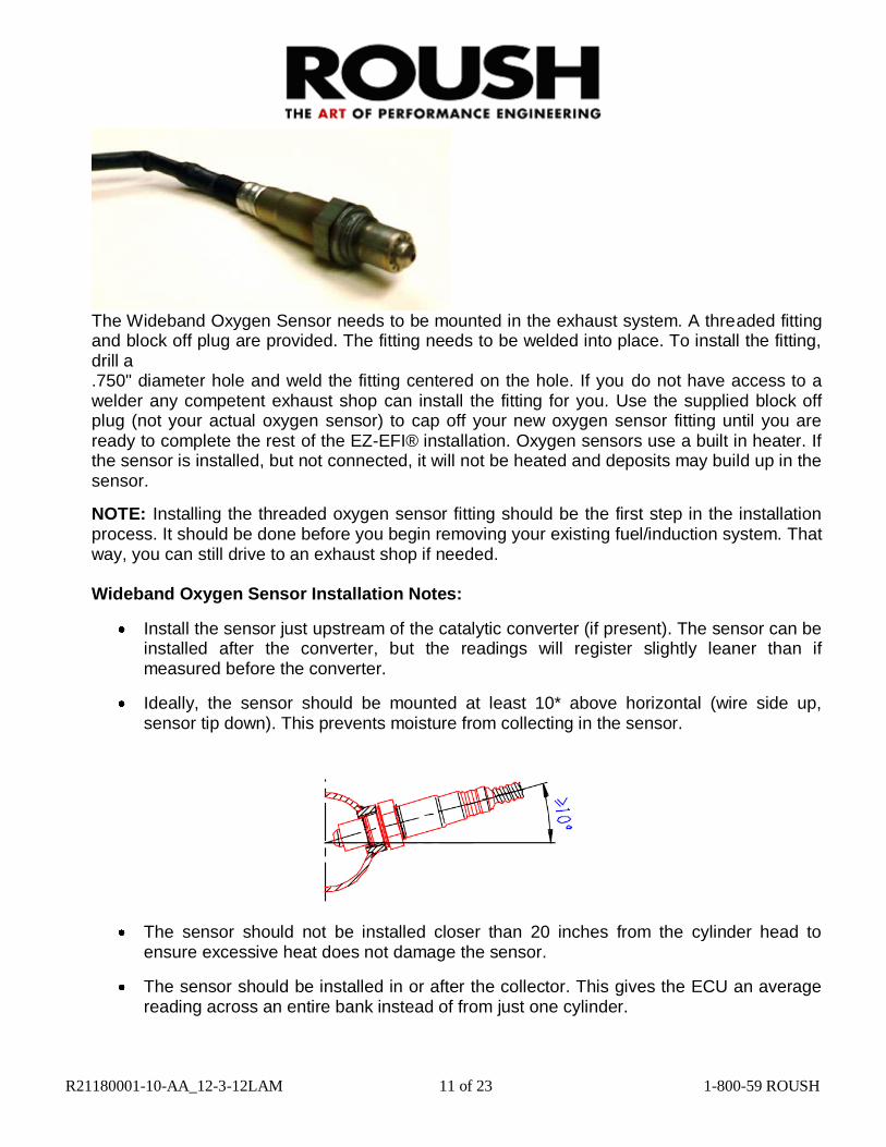
The Wideband Oxygen Sensor needs to be mounted in the exhaust system. A threaded fitting and block off plug are provided. The fitting needs to be welded into place. To install the fitting, drill a .750" diameter hole and weld the fitting centered on the hole. If you do not have access to a welder any competent exhaust shop can install the fitting for you. Use the supplied block off plug (not your actual oxygen sensor) to cap off your new oxygen sensor fitting until you are ready to complete the rest of the EZ-EFI® installation. Oxygen sensors use a built in heater. If the sensor is installed, but not connected, it will not be heated and deposits may build up in the sensor.
NOTE: Installing the threaded oxygen sensor fitting should be the first step in the installation process. It should be done before you begin removing your existing fuel/induction system. That way, you can still drive to an exhaust shop if needed. Wideband Oxygen Sensor Installation Notes:
Install the sensor just upstream of the catalytic converter (if present). The sensor can be installed after the converter, but the readings will register slightly leaner than if measured before the converter.
Ideally, the sensor should be mounted at least 10* above horizontal (wire side up, sensor tip down). This prevents moisture from collecting in the sensor.
The sensor should not be installed closer than 20 inches from the cylinder head to
ensure excessive heat does not damage the sensor.
The sensor should be installed in or after the collector. This gives the ECU an average reading across an entire bank instead of from just one cylinder.

R21180001-10-AA_12-3-12LAM 12 of 23 1-800-59 ROUSH
The sensor should not be mounted near the open end of the exhaust system. At low engine speeds, free air may reverberate into the exhaust and cause false readings.
The system will not function properly if there are any exhaust leaks. Any fresh air that gets to the sensor will cause false lean readings. The ECU will respond by adding fuel that the engine doesn’t really need.
NOTE: The use of leaded fuel will significantly reduce the lifespan of the oxygen sensor. Fuel System
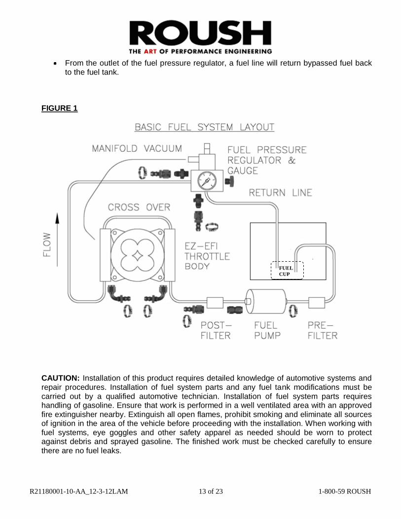
The EZ-EFI® System needs a high pressure, fuel injection rated fuel system. An optional EZ-EFI® Fuel Pump Kit is available that includes the required hardware and wiring. Fuel line and fittings are also available in an optional EZ-EFI® Hose and Fitting Kit. Whether using these kits or building a fuel system with other components, the basic layout will be as follows:
Figure 1 is a general routing schematic of a basic fuel system only. Your specific
application may vary. If unsure of the proper installation please consult a professional technician.
Your vehicle must utilize a return style fuel system.
Your vehicle’s fuel tank should utilize a fuel reserve cup in the bottom of the tank which will allow fuel to flood both in and out. This cup retains fuel near the fuel supply tube in the event of low fuel.
Starting at the tank, a fuel line will run to a pre-filter. (The pump included in the EZ-EFI® Fuel Pump kit features a built in strainer in its inlet so a pre-filter is not required.)
From the pre-filter (if used), a fuel line will connect to the fuel pump inlet. The fuel pump should be mounted near the tank and low so that it is gravity fed. NOTE: To avoid damage to the pump, do not allow it to run dry. Depending on the fittings being used, the pre-filter may attach directly to the fuel pump.
From the fuel pump outlet, a fuel line will connect to a post-filter. Depending on the fittings being used, the fuel pump outlet may attach directly to the post-filter. This is the case with the EZ-EFI® Fuel Pump kit.
From the post-filter, a fuel line will connect to one of the fuel rails on the throttle body.
The throttle body comes with a crossover to carry the fuel from one rail to the other.
From the outlet of the second fuel rail, a fuel line will connect to the inlet of the fuel pressure regulator. If using a dual inlet fuel pressure regulator, be sure to cap the unused port. (The fuel pressure regulator also needs a vacuum line connecting its vacuum reference port to manifold vacuum).
R21180001-10-AA_12-3-12LAM 13 of 23 1-800-59 ROUSH
From the outlet of the fuel pressure regulator, a fuel line will return bypassed fuel back to the fuel tank.
FIGURE 1
CAUTION: Installation of this product requires detailed knowledge of automotive systems and repair procedures. Installation of fuel system parts and any fuel tank modifications must be carried out by a qualified automotive technician. Installation of fuel system parts requires handling of gasoline. Ensure that work is performed in a well ventilated area with an approved fire extinguisher nearby. Extinguish all open flames, prohibit smoking and eliminate all sources of ignition in the area of the vehicle before proceeding with the installation. When working with fuel systems, eye goggles and other safety apparel as needed should be worn to protect against debris and sprayed gasoline. The finished work must be checked carefully to ensure there are no fuel leaks.
FUEL
CUP
CUP

R21180001-10-AA_12-3-12LAM 14 of 23 1-800-59 ROUSH
Fuel System Installation Notes:
Use fuel injection rated fuel line, filters, pump, etc. to deal with the higher fuel pressures associated with fuel injection.
Mount pump close to the fuel tank. Mount pump low so it is gravity fed from the fuel tank.
NOTE: To avoid damage to the pump, do not allow it to run dry.
The fuel tank must be vented.
Keep fuel system components away from heat and moving parts.
Use a fuel pressure regulator with a vacuum reference port.
Run a vacuum hose from a manifold vacuum port on the throttle body to the reference port on the fuel pressure regulator. This will raise and lower fuel pressure with changes in manifold vacuum.
If using a dual inlet fuel pressure regulator, be sure to cap the unused port.
Carefully inspect the fuel system for leaks – especially when it is pressurized.
It is good practice to install a fuel pressure gauge so fuel pressure can be verified later if needed. At the very least, a fuel pressure gauge must be available during initial setup so the fuel pressure can be set. A fuel pressure gauge is included with the optional EZ-EFI® Fuel Pump kit.
Fuel Pressure Fuel pressure should be set to 43 psi. This is the baseline setting for the EZ-EFI® System. This fuel pressure with the 4 injectors in the EZ-EFI® throttle body will support 550 HP.
Higher fuel pressure will increase the injector flow rates and support more power if needed. For example, the injectors are rated at 88 lb./hr. @ 60 psi. That is enough fuel for about 650 HP if the fuel system being used can supply that much fuel at that pressure. The EZ-EFI® Fuel Pump supports about 600 HP.
Fuel pressure can be checked with the engine not running. (If you check it with the engine running, be sure to disconnect the vacuum line from the reference port. Don’t forget to reconnect it when you are done! Also keep in mind that the loose vacuum line will become a vacuum leak unless you cap it off.) Watch the fuel pressure gauge at key-on as the ECU commands the fuel pump on to prime the fuel system. If the fuel pump needs to be run again, turn the ignition off for approximately 10 seconds and then back on again.
To manually keep the pump running while setting the fuel pressure, locate in the EZ-EFI® wiring harness the green wire labeled “FUEL PUMP RELAY” or the green wire in the “FUEL PUMP CONTROLLER” connector. These are both connected to the ECU’s fuel pump control. And one of them should be going to a fuel pump relay (either your own or the one built into the

R21180001-10-AA_12-3-12LAM 15 of 23 1-800-59 ROUSH
relay harness in the optional EZ-EFI® Fuel Pump kit). Ground whichever of those two wires is not connected. With the ignition on, that should trip the relay and run the pump. Turning the adjustment screw on the fuel pressure regulator changes the fuel pressure. Be sure to tighten down the jam nut when finished adjusting the fuel pressure. EZ-EFI® Fuel Pump Kit/EZ-EFI® Hose and Fitting Kit Optional kits are available that include all of the components needed to assemble a high quality, fuel injection rated fuel system. The EZ-EFI® Fuel Pump Kit consists of all the basic hardware (pump, filter, regulator, gauge, etc.) and wiring (plug in fuel pump harness with relay) needed to assemble the fuel system. For connecting everything together, an EZ-EFI® Hose and Fitting Kit is available. It includes fuel line and fittings to mate to the hardware from the EZ-EFI® Fuel Pump Kit. The fuel pump inlet uses a hose barb fitting. All other fittings are -6 AN.
EZ-EFI® Fuel Pump Kit – Pump and Fittings The EZ-EFI® Fuel Pump kit includes a high pressure, high flow fuel pump along with the associated fittings and o-rings. There is a hose barb inlet fitting and a -6 AN outlet fitting. A third fitting is included but will not be used.
EZ-EFI® Fuel Pump Kit – Wiring The EZ-EFI® Fuel Pump Kit includes a relay harness that mates directly to the “FUEL PUMP CONTROLLER” connector on the main wiring harness. It is packaged with a loose ring terminal and an insulated butt splice. The fuel pump is packaged with a connector pigtail.

R21180001-10-AA_12-3-12LAM 16 of 23 1-800-59 ROUSH
The relay harness has a long, loose red wire that feeds power to the fuel pump. Once this has been routed and cut to the desired length, use the insulated butt splice to crimp it to the red wire on the fuel pump connector pigtail. (Be sure to strip some wire insulation off of each wire first!) After making the connection, use a heat gun to shrink down the insulation. Attach the ring terminal to the black wire (again, strip off some wire insulation first) on the fuel pump connector pigtail. This needs to be grounded. You can often use one of the bolts that mounts the fuel pump.
EZ-EFI® Hose and Fitting Kit The EZ-EFI® Hose and Fitting Kit includes hose clamps for securing fuel line to the fuel tank’s outlet and return and to the inlet of the fuel pump. A -6 AN female coupling is used to connect the fuel pump outlet to the post-filter. Push fit -6 AN fittings are used for all other connections. The “Basic Fuel System Layout” diagram shows where the different fittings are used. NOTE: Soaking the hose end in boiling water before assembly will make it more pliable.

R21180001-10-AA_12-3-12LAM 17 of 23 1-800-59 ROUSH
R21180001-10-AA_12-3-12LAM 18 of 23 1-800-59 ROUSH
Installation Sequence
This is a general outline of the installation process. Read all the component specific installation notes for
more detail before beginning the installation.
1. Install the threaded oxygen sensor fitting in the exhaust system and cap it off with the block off -plug
once you are ready to complete the EZ-EFI® installation, remove the block off plug and install the
oxygen sensor.
2. Install the throttle body. Attach your return spring and throttle linkage.
3. Install the Coolant Temperature Sensor
4. Install the fuel system.
5. Determine the appropriate method for getting an engine speed input into the ECU. Install RPM
Module if needed.
6. Connect the wiring harness to all of the sensors/injectors/idle motor on the throttle body.
7. Connect the wiring harness to the Coolant Temperature Sensor, Wideband Oxygen Sensor and an
ignition box or the RPM Module.
8. Find a suitable location and mount the ECU. Make sure the wiring harness will reach the mounting
location.
9. If using the optional EZ-EFI® Fuel Pump Kit, connect the “FUEL PUMP CONTROLLER”
connection on the main wiring harness to the included relay harness. Route the relay harness back to
the fuel pump and make the final connections. Otherwise, connect the “FUEL PUMP RELAY” wire
on the main wiring harness to the negative side of a relay that feeds power to the fuel pump.
10. If you would like to have the ECU control an electric fan, connect the Blunt Cut Blue “FAN
RELAY” wire to the negative side of a relay that feeds power to the fan.
11. If you would like the ECU to bump up the idle speed and activate the fan output when an air
conditioning compressor is switched on, connect the Blunt Cut Gray “A/C INPUT” wire to the A/C
switch so that it sees power when the A/C is turned on.
12. Connect the “BATTERY POS” and “BATTERY NEG” wires DIRECTLY to the battery. Extend
the wires if necessary to reach the battery. Use automotive grade 12 gauge (or larger) wire.
13. Connect the “12V SWITCHED” wire to a switched ignition source (hot in On/Run and Crank). Do
NOT connect to the positive side of an ignition coil. 14. Connect the wiring harness to the ECU. 15. Switch on the ignition. The ECU will run the fuel pump for several seconds. Inspect the fuel system
for leaks and set the fuel pressure.
On-Board Diagnostics The EZ-EFI® system includes a robust self diagnostics feature. The ECU constantly monitors various inputs and outputs for any deviations from normal operation. If any is detected, the LED on the front face of the ECU flashes rapidly as a warning that there is a problem. (The LED will normally remain off at key-on. Then come on when the ECU detects an RPM input. It will be lit solid while the engine is running normally.) Also, the SE Status Indicator displayed on the Live Data screens acts like a Check Engine Light. It will signal if an error code has been set. The hand-held can be used to read any error codes that have been set. Once an error code is set, it is saved in the ECU until the ECU is reset by keying-off and allowing the ECU to complete is shutdown procedure (takes approximately 5-10 seconds). Or error codes can be cleared with the hand-held at any time.

R21180001-10-AA_12-3-12LAM 19 of 23 1-800-59 ROUSH
The following error codes are possible:
Faults Monitors
CTS Coolant temperature sensor open or short
ATS Air temperature sensor open or short
MAP Manifold absolute pressure sensor open or short
TPS Throttle position sensor open or short
Wideband O2 Wideband oxygen sensor open or short or Wideband O2
Voltage Battery voltage below 7V or above 19V for 10 seconds
IAC Idle motor fault reported by IAC control chip
Inj DC Limit
Injector duty cycle over 100% (an indication that injectors
cannot supply enough fuel. The ECU has determined that
the injectors need to be open longer than the time
available.)
Troubleshooting CTS, ATS, MAP, TPS, Wideband O2 and IAC Faults
Verify that the offending sensor is installed and connected to the wiring harness.
With the ECU keyed-on, use the hand-held to look for a valid reading from the offending sensor. (for IAC, watch for a changing reading with the engine idling.)
Verify that the wiring harness itself is not damaged. Visually inspect the wiring harness from the sensor back to the ECU looking for cut, pinched, abraded or melted sections. Using a multi-meter, check continuity from the sensor connector back to the ECU. Also make sure no pins in a particular sensor connector are shorted to each other.
For the wideband oxygen sensor, also check to see if the sensor tip gets hot (check carefully!) with the ECU keyed-on.
If no other problems can be found, try replacing the sensor.
Troubleshooting Voltage Fault
Verify that the battery and charging system are in good condition.
Verify solid, corrosion free connections at the battery and switched ignition source.
Verify that the wiring harness itself is not damaged. Visually inspect the wiring harness looking for cut, pinched, abraded or melted sections.
Verify that the fuse in the wiring harness is installed and in good condition.

R21180001-10-AA_12-3-12LAM 20 of 23 1-800-59 ROUSH
Troubleshooting Inj DC Limit Fault
Verify there is plenty of fuel in the tank.
Verify static fuel pressure – watch the fuel pressure gauge at key-on as the ECU turns on the fuel pump to prime the fuel system. 43 psi of fuel pressure with a single EZ-EFI® Throttle Body and injectors will support 550 HP.
Verify fuel pressure during a wide open throttle run. Have an assistant monitor the reading on a remote fuel pressure gauge while you drive. For safety, the remote fuel pressure gauge should not be routed inside the vehicle. Fuel pressure at wide open throttle should equal the static pressure (fuel pressure with the fuel pump on and the engine off). If it is significantly lower, the fuel system is not keeping up with the engine’s fuel demand.
De-pressurize the fuel system. Remove the fuel rails and check for any debris in the top side of the injectors.
Check for any debris in the fuel pump/fuel filters.
If the engine is legitimately making more than 550 HP, the fuel pressure can be increased to get more flow out of the injectors. For example, the injectors are rated at 88 lb/hr @ 60 psi.
That is enough fuel for about 650 HP if the fuel system being used can supply that much fuel at that pressure. The EZ-EFI® fuel pump supports about 600 HP. If the fuel pressure is changed, you MUST go back through the hand-held’s setup wizard.
(NOTE: If the injectors really are undersized, it is likely only a problem at high RPM and high
load. Unless there is a major, fundamental failure in the fuel system, an Inj DC Limit fault hould not mean it is unsafe to run the engine. Just be careful to avoid high RPM/high load until the injector sizing issue has been resolved.) When an error code is set, learning will be disabled until it is cleared. The two exceptions to this are the IAC and Inj DC Limit faults. An IAC fault does not disable learning because a failed IAC does not affect the fueling calculations. An Inj DC Limit fault does not permanently disable learning. Instead it only temporarily disables learning while injector duty cycle is above 100%. Once injector duty cycle drops back below 100%, learning can resume.

R21180001-10-AA_12-3-12LAM 21 of 23 1-800-59 ROUSH
Engine Protection/Limp Mode Besides being a powerful trouble shooting tool, the on-board diagnostics also protect the engine. Contingency plans are built into the ECU so that if a sensor fails, protective action can be taken. If, for example, there is a problem with the coolant temperature sensor, the ECU’s electric fan control output will be switched on to guard against over heating. Also, if the ECU detects a problem with a sensor, it will switch to using pre-programmed default values in the affected part of the fueling calculations. This puts the ECU into “limp” mode. If there is a problem with any of the sensors, the engine can still run so the vehicle will not be stranded. (The exception is the RPM signal feeding into the “TACH IN/RPM MODULE” wire. Without an engine speed input, the engine will not run.) Depending on circumstances and which sensor has failed, the change in the engine’s behavior may be very obvious or it may be hardly noticeable. If you notice any change in how the engine is running, it’s a good idea to check the LED on the ECU (it will flash) or the SE Status Indicator on the Live Data screens. These both signal that an error code has been set. Or you can go directly to the Error Code section of the hand-held. Even if the engine is running well, an error code will prevent further learning. Also, the problem that caused the error code to be set may have a larger effect later under different conditions. Keep in mind that the error codes are cleared when the ECU is reset (key-off for approximately 5-10 seconds). So if you suspect a problem, it is best to check for error codes before powering down the ECU. A persistent problem (sensor disconnected, for example) will set an error code when the ECU is keyed-on. But an intermittent problem may only be detected while the engine is running. Load Indexed Speed Density The EZ-EFI® system operates with a fuelling strategy known as Load Indexed Speed Density. Just like a traditional Speed Density system, it uses manifold pressure, air temperature and engine speed along with other considerations to calculate the proper amount of fuel to inject. At wide open throttle, manifold pressure is equal to the ambient atmospheric pressure. If you drive at high altitude, the ECU would see a lower manifold pressure at wide open throttle (since atmospheric pressure is lower) than it would at sea level. A traditional Speed Density strategy uses manifold pressure to locate values in various lookup tables. So the engine would operate differently at high altitude than it would at sea level. The EZ-EFI® system’s Load Indexed Speed Density avoids this inconsistency by using a calculated “Load” for table look ups instead of raw manifold pressure. This “Load” is a comparison of the current manifold pressure vs. the ambient atmospheric pressure. This means that at any altitude, full throttle (or any other throttle position) operates on the same parts of the look up tables. At full throttle at high altitude, the ECU will still see manifold pressure that is lower than it would at sea level. But because that lower manifold pressure is equal to the ambient atmospheric pressure, it is still considered 100% load. This all happens behind the scenes and requires no special attention from the driver.

R21180001-10-AA_12-3-12LAM 22 of 23 1-800-59 ROUSH
LT. GREEN
BLUE
GRAY

R21180001-10-AA_12-3-12LAM 23 of 23 1-800-59 ROUSH
WARRANTY
FOR ENGINE WARRANTY INFORMATION PLEASE REFER TO THE ROUSH
PERFORMANCE WEBSITE AT WWW.ROUSHPERFORMANCE.COM, OR CALL THE
ROUSH PERFORMANCE HELP DESK AT (800) 59-ROUSH