Roundabout Design - 1 Project Overvie · Roundabout Design - Project Overview Course Name here...
56
Roundabout Design - Project Overview Course Name here Copyright © 2002 Bentley Systems, Incorporated Do Not Duplicate 9/15/2008 1-1 1 CHAPTER OBJECTIVES In this chapter we will: Overview the original data supplied for this project. Formulate a design strategy INTRODUCTION Designers will realize that every “at grade” intersection has it’s own specific design issues. What may look the same from plan view may be a totally different design vertically due to the existing vertical conditions or specific requirements. The amount of reconstruction of existing roadway can completely change the designers approach to two seemingly similar geometrical layouts. Horizontally, the vehicle types and volumes can drastically alter the layout of the roundabout and its approaches. We shall investigate one set of design constraints based on certain assumptions for this particular project and formulate a design strategy. We will overview the supplied data and constraints for this specific situation and investigate the effects of altering some of the data. Disclaimer: This is NOT a course to teach the principles and theories of roundabout design. It is a course to introduce the user to the roundabout layout tool and the methods available in site modeler to perform the vertical design. The author will be first to point out that he is not an expert on roundabouts since few have been built in my home state. It is a safe bet that an expert in roundabouts will find aspects of the design presented here that can be improved for a more appropriate design. It is the express desire that this course will enable the expert user to take the author’s knowledge of the tools and apply the lessons to perform truly expert roundabout layout and design.
Transcript of Roundabout Design - 1 Project Overvie · Roundabout Design - Project Overview Course Name here...

Roundabout Design -
Project Overview
Course Name here Copyright © 2002 Bentley Systems, Incorporated Do Not Duplicate
9/15/2008 1-1
1 CHAPTER OBJECTIVES
In this chapter we will:
Overview the original data supplied for this project.
Formulate a design strategy
INTRODUCTION
Designers will realize that every “at grade” intersection has it’s own specific design issues.
What may look the same from plan view may be a totally different design vertically due to the existing vertical conditions or specific requirements.
The amount of reconstruction of existing roadway can completely change the designers approach to two seemingly similar geometrical layouts.
Horizontally, the vehicle types and volumes can drastically alter the layout of the roundabout and its approaches.
We shall investigate one set of design constraints based on certain assumptions for this particular project and formulate a design strategy. We will overview the supplied data and constraints for this specific situation and investigate the effects of altering some of the data.
Disclaimer: This is NOT a course to teach the principles and theories of roundabout design. It is a course to introduce the user to the roundabout layout tool and the methods available in site modeler to perform the vertical design. The author will be first to point out that he is not an expert on roundabouts since few have been built in my home state. It is a safe bet that an expert in roundabouts will find aspects of the design presented here that can be improved for a more appropriate design. It is the express desire that this course will enable the expert user to take the author’s knowledge of the tools and apply the lessons to perform truly expert roundabout layout and design.

Project Overview
Course Name here Copyright © 2008 Bentley Systems, Incorporated Do Not Duplicate
9/15/2008 1-2
PROJECT OVERVIEW
This training session evolved from an actual project which has been designed and built. The original project had a large traditional intersection where this workshop will explore a roundabout.
Note NOTE: Since we are inserting a roundabout into a situation where it was not originally intended there might be some areas in the approaches to the roundabout which could have been better designed. This is the first of an entire series of lessons for site modeler and the emphasis was to prepare a workshop for roundabouts. As other lessons using this dataset become developed then these inconsistencies should disappear and this workshop will be revised. For example, the eastern approach is a two lane approach which feeds into a one lane roundabout. This is certainly not a good idea and was not a part of the actual project design and construction.
The overall project consists of a large site development which includes a high school campus, a single unit residential area, a multiunit residential area and large commercial area. There is a significant road network which includes a roundabout in the area in front of the school which is the focus of this workshop.
Overview the supplied data and design constraints.
1. Open the file …\RoundaboutSchool\Chapter2\RoundaboutAtSchool.dgn.
2. We shall discuss in the class the job requirements and design parameters.
Note This shows all of the plan view graphical elements required to begin this project. The road layout elements to the north, south, east and west are the elements that will be designed in other lessons. In this lesson we will fill in the hole with a 4 way roundabout.

Design Strategy
Course Name here Copyright © 2002 Bentley Systems, Incorporated Do Not Duplicate
9/15/2008 1-3
DESIGN STRATEGY
Formulate a Design Strategy.
Hint There are a number of different design philosophies for designing roundabouts. We will not be examining all of the different theories in this class. The philosophy that we will use is one that treats the traffic circle portion of the intersections as an “upside down plate”. This means that irrespective of the orientation of the traffic circle, the outside edge is always forms a plane surface.
CONSTRAINTS
Minimize cut/fill in the area of the traffic circle.
Minimum approaches to the roundabout. The remainder of the roads will be designed using other tools.
Keep in mind that sidewalks will be a part of the ultimate design which comes later. In particular we need to avoid the sidewalks drawn southeast of the roundabout since those sidewalks will be done as an independent design to tie into the sidewalks on the pedestrian overpass.
DESIGN STRATEGY
1. We will use the Roundabout layout tool to do the horizontal design of the traffic circle and the minimum approaches.
2. Make edits to the roundabout parameters to tweak the horizontal design.
3. Once the horizontal layout is completed, make duplicates of the line work for use in Site Modeler.
4. Perform the vertical design in site modeler with the following steps.
4.1. Create a temporary grading surface to establish orientation of the circle.
4.2. Drape the outer circle onto the temp object
4.3. Define inner circle with a slope from the outer circle
4.4. Define alignment and profile for each approach.
4.5. The incoming roadway profiles will be designed based on the traffic circle elevations.
4.6. Curb returns will initially be defined based on the most appropriate adjacent element then modified as required
4.7. The median islands will be created based on the finished pavement surface


Roundabout Design -
Horizontal Layout of the
Roundabout
Course Name here Copyright © 2008 Bentley Systems, Incorporated Do Not Duplicate
9/15/2008 2-1
2 CHAPTER OBJECTIVES
In this chapter we will:
Place the roundabout using the roundabout tool, utilizing a preconfigured roundabout design library.
Adjust the roundabout parameters to match our design needs and to match the approaches.
Investigate the various edits available in the roundabouts design.
Investigate the roundabout design library and discuss how to create additional custom libraries for your own use.
PLACE THE ROUNDABOUT
Overview
3. Open the file …\RoundaboutSchool\Chapter2\RoundaboutLayout.dgn.
4. When the Roundabouts tool is installed you will see a Civil group of tools in the task navigation area as shown below.
Note In the image above I have configured my installation of Microstation to use the “Dialog” form of task navigation for easier identification. You can set this at Workspace > Preferences > Task navigation.

Place the Roundabout
Course Name here Copyright © 2008 Bentley Systems, Incorporated Do Not Duplicate
9/15/2008 2-2
5. Click and hold the Open Library Browser item and choose “Open as toolbox”.
6. This opens the toolbox for those who prefer to work this way.
The first icon is to open the library browser, which we will explore in a few minutes.
The second icon is to replace an approach. Basically what it does is allow you to set up parameters once on a single approach and copy these settings to a second approach.
The third icon is to update alignments. We will lay out our roundabout based upon a graphical alignment. If something happens to change these alignments then we can use this tool to redesign the roundabout to match.
The fourth icon is the entry curve path analysis tool.
The fifth icon is to bring up the civil preferences. These preferences are mainly colors for manipulators and design speed factors.
Place the Roundabout
Course Name here Copyright © 2008 Bentley Systems, Incorporated Do Not Duplicate
9/15/2008 2-3
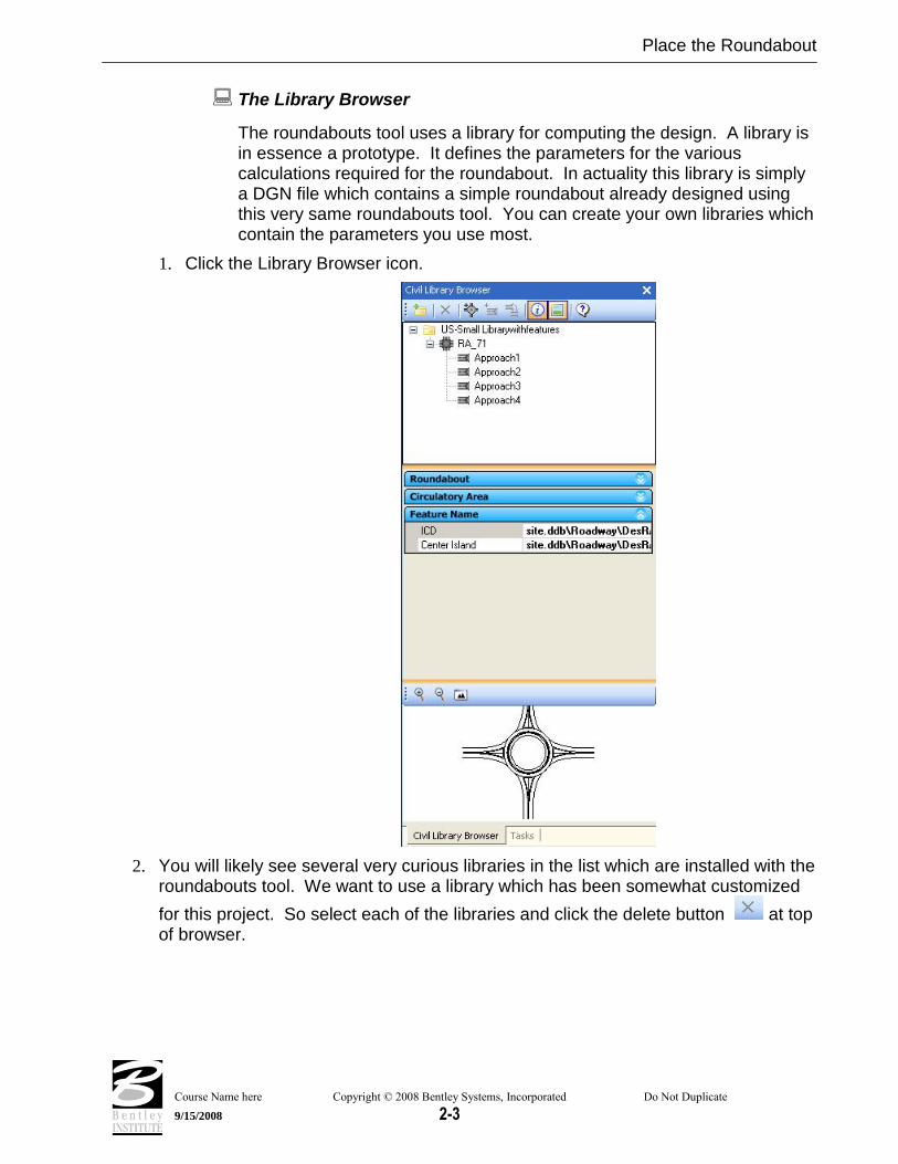
The Library Browser
The roundabouts tool uses a library for computing the design. A library is in essence a prototype. It defines the parameters for the various calculations required for the roundabout. In actuality this library is simply a DGN file which contains a simple roundabout already designed using this very same roundabouts tool. You can create your own libraries which contain the parameters you use most.
1. Click the Library Browser icon.
2. You will likely see several very curious libraries in the list which are installed with the roundabouts tool. We want to use a library which has been somewhat customized
for this project. So select each of the libraries and click the delete button at top of browser.

Place the Roundabout
Course Name here Copyright © 2008 Bentley Systems, Incorporated Do Not Duplicate
9/15/2008 2-4
3. Now click the ADD button and select the following library.

Place the Roundabout
Course Name here Copyright © 2008 Bentley Systems, Incorporated Do Not Duplicate
9/15/2008 2-5
4. Select the RA line in the browser and expand the items in the properties pane below. This allows inspection of, but not editing of, the parameters defined in the library. To edit the library we actually open the DGN file containing the library and edit the roundabout itself.
5. Similar properties can be reviewed for each of the approaches.

Place the Roundabout
Course Name here Copyright © 2008 Bentley Systems, Incorporated Do Not Duplicate
9/15/2008 2-6
Create the Roundabout
Now, let’s create the actual roundabout.
1. With the RA line in browser selected the Place Roundabout button becomes active.
Click the button.
2. One of the new concepts in the Civil Platform products of which the Roundabouts tool is a part is the use of heads up interface feedback. You will see prompts at the cursor to direct you to what is being asked for input. In this case you are prompted to select the reference element.
3. The reference element is the alignment for one of the approaches. Pick the approaches as shown below.
4. Once all three alignments are picked (the north-south line goes straight thru), then click the reset button to stop picking.

Place the Roundabout
Course Name here Copyright © 2008 Bentley Systems, Incorporated Do Not Duplicate
9/15/2008 2-7
5. Now you are prompted to set the center of the roundabout.
6. Snap to the intersection of the alignments as shown above.
Note You do not have to snap to the intersection. Wherever you click (or snap) will be the center of the roundabout. Of course, there are certain advantages to using the intersection to make the roundabout symmetrical. Also, there is no requirement that the alignments must intersect. The only requirement is that each approach alignment must intersect the circulatory area of the traffic circle.
7. The roundabout is placed as shown below. Note the gaps and overlaps on the approaches. And the eastern approach is too narrow. Don’t worry about these. We’ll address them in the next lesson.

Place the Roundabout
Course Name here Copyright © 2008 Bentley Systems, Incorporated Do Not Duplicate
9/15/2008 2-8
Modifications to Roundabout
1. As noted above, the default design from the library does not exactly fit our needs. That’s OK since it is only intended as a start point. We can now tweak the design to match our needs.
2. First of all, the traffic circle can perhaps be made larger to improve traffic flow. Click on the outer circle and note that the radius is presented to us as 90.0 feet.
3. Hover over the 90.0 and it will changes colors. Once it changes color, we can click and edit the value. Change the value to 100, and the entire roundabout will recalculate.
4. Note also the center point manipulator. We could (but will not) click and drag this pip to reposition the circle and the roundabout will recalculate.

Place the Roundabout
Course Name here Copyright © 2008 Bentley Systems, Incorporated Do Not Duplicate
9/15/2008 2-9
5. Now, let’s turn our attention to the west approach. We can see that the approach is designed past the point where we want to stop. Let’s adjust this length.
6. Open Microstation’s Element Information tool.
7. Use the Power Selector and select the roundabout, picking it where shown above.
8. You can pick anywhere there is a roundabout element. It is sometimes a little finicky and you may have to try a few times until you get accustomed to the process.
9. Keep in mind that there is an embedded intelligent roundabout object as well as visible graphics. We are after the roundabout object. When you get the right thing you will see the roundabout properties in the element information dialog.

Place the Roundabout
Course Name here Copyright © 2008 Bentley Systems, Incorporated Do Not Duplicate
9/15/2008 2-10
10. Once selected and the roundabout properties are available in element info click on the western approach. The approach graphics will highlight corresponding to which approach is selected in element info.
11. One of the approach properties is the approach length as shown above. Change the property for “Approach Length Type” from “Length” to “Point”
12. The approach calculations will change to cover the entire alignment and look really bad.

Place the Roundabout
Course Name here Copyright © 2008 Bentley Systems, Incorporated Do Not Duplicate
9/15/2008 2-11
13. There will also appear an anchor manipulator at the end of the alignment. Click and drag this pip to snap to the end of our existing approach graphics.

Place the Roundabout
Course Name here Copyright © 2008 Bentley Systems, Incorporated Do Not Duplicate
9/15/2008 2-12
14. Once you drag the end point then the approach will heal itself.
15. See, told you not to worry.
16. Now, repeat this exercise with the north and south approaches.
Note These will be a little more tricky because the alignments are so long. You may need to zoom out and drag the anchor point multiple times.
Modify the East Approach
1. The east approach will need a little more modification. The length needs adjustment as we did on the other approaches and the width parameters need adjustment.
2. Adjust the length by point using the same procedure you used above for other approaches.

Place the Roundabout
Course Name here Copyright © 2008 Bentley Systems, Incorporated Do Not Duplicate
9/15/2008 2-13
3. Now we need to adjust the width of the “central reserve”. In this case the central reserve serves us as the central median to match the rest of the approach. We can change this in the element information
4. Or, by selecting the approach and zoom in until you can see the manipulator text.

Place the Roundabout
Course Name here Copyright © 2008 Bentley Systems, Incorporated Do Not Duplicate
9/15/2008 2-14
5. Whichever way you choose, change the width to 8.0 to match the rest of the approach roadway.
6. You will get an error on the island when you make this change. We’ll explore this error later.
7. Similarly change the lane widths from 15.0 to 24.0 feet. Once this is done then our approaches are mostly complete.
8. Note that there has appeared 3 little icons on the median island. One is a red error message and 2 are informational messages. To see what these are open the message center by clicking on the message center tool in the task navigation.

Place the Roundabout
Course Name here Copyright © 2008 Bentley Systems, Incorporated Do Not Duplicate
9/15/2008 2-15
9. The message center will open, probably docked at the bottom of your Microstation window. Here we see descriptions of the messages
Note In this case it is simple to determine where the problems are located. Sometimes though you can have a long list and it is not easy to determine where the problem is that corresponds to the message. You can right click any message in the message center and zoom to the location of the problem.
10. The first is that we have developed a problem with the radius on the back of our island. It may not be immediately apparent what is the problem. A clue is that the problem surfaced when we increased the width of the central reserve. What has happened is that we have created an impossible set of parameters. Changing the back radius to 8.0 feet should solve the problem and make the error go away.
11. We probably also want to change the side offset of the islands from 2.0 to 0.0 so our island will match up to the median divider on the rest of the approach. This may necessitate changing the back radius again.

Place the Roundabout
Course Name here Copyright © 2008 Bentley Systems, Incorporated Do Not Duplicate
9/15/2008 2-16
12. Now we have cleared the error. The remaining informational messages are telling us that the entrance and exit widths are narrower than the lanes, which of course, is contrary to desired standards.
13. Change the parameter for “theoretical entrance width” to 24.0 to clear the informational messages.

Roundabout Design -
Prepare Data for Vertical
Design
Course Name here Copyright © 2008 Bentley Systems, Incorporated Do Not Duplicate
9/15/2008 3-1
3 CHAPTER OBJECTIVES
In this chapter we will:
Prepare the graphics produced by the roundabouts tool for use in Site Modeler for vertical design.
INTRODUCTION
The graphics produced by the Roundabouts tool are part of an intelligent object model, which we want to keep intact, in case we want to make future edits later.
If we had our rathers, we could use these graphics in their current form directly in site modeler. But in the current version of software, this is not possible.
What we will do is create a duplicate of the roundabout graphics for use in site modeler. Here’s the complete workflow, including some steps we have already completed in previous chapters:
1. We did the roundabout design and layout in RoundaboutLayout.dgn. This DGN file contains only the roundabout object.
2. Our design file is RoundaboutAtSchool.dgn which we referenced to the layout.dgn so we could see the rest of the project in relation to the roundabout.
3. We now open the RoundaboutAtSchool.dgn file which has the layout referenced.
4. We select and copy the roundabout graphics into the RoundaboutAtSchool.dgn. this preserves the roundabout object while making the graphics available to us.
5. To make the vertical design possible, we drop the roundabout flares, which creates 3 arcs from each of the flares.
6. We form the arcs in the traffic circle into true circles
7. We need to drop the islands into elements or form into a shape rather than the complex chain which is created by the roundabouts tool.

Introduction
Course Name here Copyright © 2008 Bentley Systems, Incorporated Do Not Duplicate
9/15/2008 3-2
Note Any future edit to the roundabout object will require redesign of the vertical in the affected portion. Changes to the roundabout graphics will not automatically filter through because there are currently no links between the roundabout object and the site modeler.
Prepare the graphics for vertical design
1. Open the file …\RoundaboutSchool\Chapter2\RoundaboutAtSchool.dgn.
2. Open reference manager and turn off the reference display of the referenced file.
3. Note the gap in the graphics. We left this gap on purpose since we knew we would design the roundabout with the roundabout tool.
4. Turn the reference display back on.

Introduction
Course Name here Copyright © 2008 Bentley Systems, Incorporated Do Not Duplicate
9/15/2008 3-3
5. Now turn off the levels in the active file, leaving only the referenced roundabout layout visible.
6. Turn on/off the reference levels as shown below.

Introduction
Course Name here Copyright © 2008 Bentley Systems, Incorporated Do Not Duplicate
9/15/2008 3-4
7. Using Power Selector, select all the visible roundabout elements.
8. Now if we use the Microstation copy command we can copy the elements into active DGN for use in modeler, while leaving the original roundabout object intact.
Note Be sure to use a snap point when copying to preserve the spatial relationship when you copy the graphics.
9. Now turn off the reference file in reference manager.
10. Turn the levels back on for the active DGN.
11. Use Power Selector and hover over one of the flares where the roundabout approaches come into the traffic circle. Note how the flare is a complex string which follows along two approaches.
12. We will need to compute these arcs with cross-slopes from different directions so use the MS drop command to drop the complex chain.

Introduction
Course Name here Copyright © 2008 Bentley Systems, Incorporated Do Not Duplicate
9/15/2008 3-5
13. Drop all four of the flares and note that they are now seperate arcs.
14. The 360 degree arcs created by the roundabouts tool will cause us problems in site modeler. Replace these with circle by snapping to center of the intersections. The outside is 100 feet radius and the inside is 85 feet.
Note This last step helps us make a better surface model. Circles are better behaved in modeler than a 360 degree arc.


Roundabout Design -
Vertical Design with Site
Modeler
Course Name here Copyright © 2008 Bentley Systems, Incorporated Do Not Duplicate
9/15/2008 4-1
4 CHAPTER OBJECTIVES
In this chapter we will:
Use the Site Modeler (Geopak or PowerCivil) to do the vertical design for the roundabout.
INTRODUCTION
Our process for doing the vertical design will be:
1. Create a temporary grading surface to define the surface of the traffic circle.
2. Drape the outer edge of circle on this surface to create the traffic circle.
3. Compute cross-slope to inner edge of circle
4. Create approach profiles
5. Compute approach edges
6. Compute the approach flares (returns). Then check / recomputed the flare profiles.
7. Add curb & gutter and sidewalks to edges of pavement.
8. Add complex cub section to inner circle
9. Add islands complete with curb.

Create a Construction Object
Course Name here Copyright © 2008 Bentley Systems, Incorporated Do Not Duplicate
9/15/2008 4-2
CREATE A CONSTRUCTION OBJECT
A construction object is defined as a site modeler object that is in the modeler project but not necessarily part of the model. Its primary use is to simplify the process of assigning, and then reassigning, elevations to irregular or complex site modeler elements.
The methodology we shall use to create the construction object is to create a new Object and, within that Object, define a surface plane based on the Control Alignment.
Open an existing project.
1. Open the DGN file …Chapter4\RoundaboutAtSchool.dgn
2. Select the site modeler tool (Applications > GEOPAK Site > Site Modeler > Site Modeling).
Note In PowerCivil select (Civil > Modeler)
3. Click Browse. Select the file …RoundaboutAtSchool.gsf.
Note This is a Site Modeler project that has already been created that includes the existing ground TIN file as the Object “Ground 1” and a Model called “RAB” that has the Ground 1 Object as its base.
4. Click OK.

Create a Construction Object
Course Name here Copyright © 2008 Bentley Systems, Incorporated Do Not Duplicate
9/15/2008 4-3
Create a Construction Object.
1. Select the new object tool (Modeler > Object > New).
2. Select object type “Construction” and name “Temp1” as shown above. Also make sure to turn off the check mark for “Add to Active Model”
Hint We are not including this object in the model because it is not part of our design. This object will be used simply to define a surface on which to drape our traffic circle.
3. Click OK.
Create the construction surface using Composite Section.
1. Select the composite section tool (Modeler > Tools > Composite Section).
2. File > Open. Select the Composite Sections setting file …TempObjectSlope.sec.
3. Turn on the check mark to “Add to Active Object” and set the object to Temp1.

Create a Construction Object
Course Name here Copyright © 2008 Bentley Systems, Incorporated Do Not Duplicate
9/15/2008 4-4
4. Set the Primary Element Definition to “Chain-Profile” and then press the Alignment Definition button and set as shown below. The feature “TempCL” is located in D&C Manager at Drafting Standards > General > TempCL.
Note The Entrance3 Alignment is the alignment which runs north-south through the roundabout and has been created in advance, along with the accompanying profile.
5. Click Apply.
We have now created a surface that is 220 feet wide (110 feet both sides of the control alignment) and is projected at 1% from on the control alignment.

Create the Roundabout Object
Course Name here Copyright © 2008 Bentley Systems, Incorporated Do Not Duplicate
9/15/2008 4-5
CREATE THE ROUNDABOUT OBJECT
We will now start to create the elements that will make up our roundabout. We first need to create an object to place the roundabout elements into. Then we will drape the outside edge of the traffic circle onto the Construction Object. Last step is to create the inside edge of the traffic circle to give us the 2% pavement cross slope within the traffic circle.
Create the Roundabout Object.
1. If you have not done so already, save your site project. (Modeler > Project > Save.)
2. On the Active Site Object Control set the active model back to RAB.
3. Now create a new object (Modeler > Object > New).
4. Select they Object type “Roadway”.
5. Overwrite the default Object Name with “RAB1”.
6. Toggle ON Add to Active Model.
Note This object is an actual part of our design so we add it to the model.
7. Click OK.

Create the Roundabout Object
Course Name here Copyright © 2008 Bentley Systems, Incorporated Do Not Duplicate
9/15/2008 4-6
Create outside edge of traffic circle element.
1. Select the new element tool (Modeler > Elements > New/Edit)
2. Set dialog as shown below.
3. Click Define Elements > Select Elements. (indicated by arrow above)
4. Select the outside edge of the traffic circle.
5. Click Apply.

Create the Roundabout Object
Course Name here Copyright © 2008 Bentley Systems, Incorporated Do Not Duplicate
9/15/2008 4-7
Create the inside edge of the traffic circle.
1. We will use the slope-offset option of the New/Edit element tool to compute the inside edge of the traffic circle. Select Modeler > Elements > New/Edit.
2. Populate the dialog as shown below.
3. Click the select elements button and pick the inside edge of the traffic circle.
4. Click Select Reference and pick, then accept, the outside edge of the traffic circle. This is the element the 2% slope will be calculated from.
Note The mouse click sequence can be awkward to some users. After picking the outside edge, click once more to accept the pick.
5. Click Apply.
6. If you have not done so already, save your site project. (Modeler > Project > Save.)
There should be a new element created and the contours of the RAB Object should indicate a 2% pavement cross slope.
Note This cross slope can be interrogated using the Analysis>Height tool.

East and West Approach Profiles
Course Name here Copyright © 2008 Bentley Systems, Incorporated Do Not Duplicate
9/15/2008 4-8
EAST AND WEST APPROACH PROFILES
Create Model surface profiles.
1. Open another Microstation window (view 2) and pan across to an empty portion of screen. We will use this window for working with profiles.
2. Select the draw profiles tool (Modeler > Object > Draw Profiles)
Note The Draw profile dialog should be familiar to most students as it is a standard GEOPAK tool. When used as a Site Modeler tool, it has additional functionality. It has the ability to not only create profiles from TIN files, but also from Site Objects and Models.
3. Set Job Number to 1.
4. Set Chain to Entrance which is the name of the east approach.

East and West Approach Profiles
Course Name here Copyright © 2008 Bentley Systems, Incorporated Do Not Duplicate
9/15/2008 4-9
5. Click Dialog Profile Cell Control button.
6. Click Place Profile Cell button. (indicated by arrow)
7. Populate the dialog as shown below.
8. Place the Profile cell into a clear part of the graphics (in Window 2).
9. Populate the Draw Profile dialog as shown below.
10. Set the Details portion of the dialog.

East and West Approach Profiles
Course Name here Copyright © 2008 Bentley Systems, Incorporated Do Not Duplicate
9/15/2008 4-10
11. Click Add Surface Settings.
12. The Details>Display Settings show that a Design and Computation Manager item is used. This item can be found within the D&C Manager as Drafting Standards>Profiles>ExProCL.
13. The same process will now be repeated to create the Model profiles for chain Entrance2.

Create Design Profiles.
Course Name here Copyright © 2008 Bentley Systems, Incorporated Do Not Duplicate
9/15/2008 4-11
CREATE DESIGN PROFILES. Now that we have drawn the Model surface profiles, we are in a position where we can create design profiles. We already have some constraints that affect this next step.
The Model profiles show us the elevation at the proposed traffic circle edge – so the design profiles must start at that elevation.
The cross slope of the traffic circles is 2%. For us to get a smooth transition for the incoming roadways to the traffic circle, we must start the design profiles using a 2% tangent from the location that we join to the traffic circle.
We have visual cues for the length of the approaches. We need to end the profiles where the roundabout graphics (edges of pavement) meet the other graphics which will be designed by other tools.
Creating Design Profiles using the Vertical Component tools.
1. Open Active Chain Control (Applications > Site > Site Modeler > Active Chain Control)
2. Set active chain control to the chain Entrance.
3. Use Microstation view controls and active chain control to zoom into the area to be profile designed.
4. Start the component profile tools (Applications > GEOPAK Site > Geometry > Layout Profile (Component Based))
Note PowerCivil, (Civil > Profiles > Layout Profiles (Component based))
Tangent Tools Curve Tools
Store Alignment
5. Tear off the tangent tools and the curve tools.
Hint These tools provide an alternate to the VPI based Vertical Alignment Generator. They allow the user to place vertical components (tangents and curves) to assemble a profile. Where the user has many constraints (as is the situation here) these are a very useful alternative to the traditional VPI profile method.
6. From the tangent tools, click Create Profile Line by Points.
7. Snap to the end of the Model profile that represents the elevation at the edge of the traffic circle.

Create Design Profiles.
Course Name here Copyright © 2008 Bentley Systems, Incorporated Do Not Duplicate
9/15/2008 4-12
8. Set the slope to 2%.
9. Draw in the tangent.
10. From the Curve tools, click Create Profile Curve by 3 Points.
11. Set the Microstation snap control to nearest.
12. Snap to 3 locations on the Model profile in the area of the extent of reconstruction.
Note This gives us a vertical curve that represents the existing road - so we can join back to existing.
Create Design Profiles.
Course Name here Copyright © 2008 Bentley Systems, Incorporated Do Not Duplicate
9/15/2008 4-13
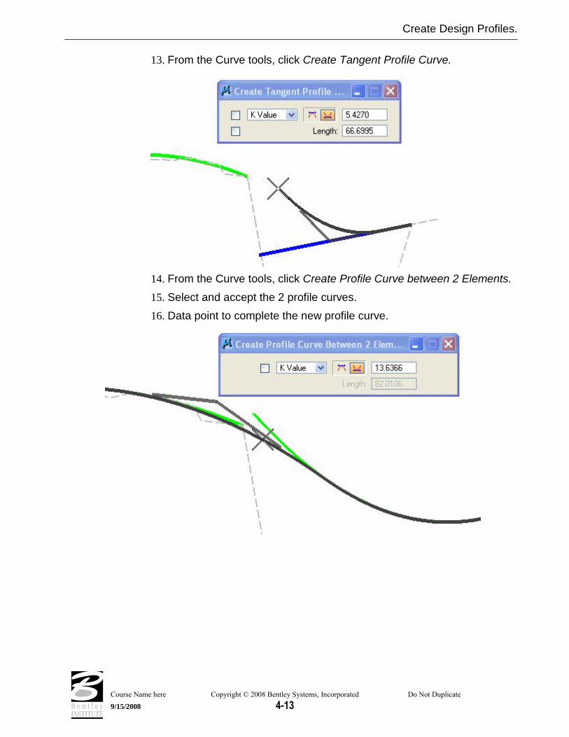
13. From the Curve tools, click Create Tangent Profile Curve.
14. From the Curve tools, click Create Profile Curve between 2 Elements.
15. Select and accept the 2 profile curves.
16. Data point to complete the new profile curve.

Create Design Profiles.
Course Name here Copyright © 2008 Bentley Systems, Incorporated Do Not Duplicate
9/15/2008 4-14
Storing the Proposed profile.
1. From the vertical components tools, click Store Vertical Alignment.
Note If you receive alert messages that cogo needs to open then answer in the affirmative. The alert message is telling us that we need COGO open to store the vertical profile and then asking us if we want to open COGO. After answering these prompts then you will need to start the store vertical alignment tool again
2. Key in the proposed profile name “Entrance”.
3. Select any proposed profile component from the profile view (Window 2).
4. Data point again to string the components together.
5. Data point again to actually store the alignment to COGO.
6. Click COGO – this will raise the COGO window. You can see the commands that have been created to store the profile.
Hint Remember to follow the prompts displayed in the Microstation message area during the design and store profile process.
Hint If desired then the stored profile could be now be loaded into the VPI profile tool in order to round off the grades and stations of VPIs as well as check curve lengths for design speed.
Now repeat the proposed profile design for Entrance2.

Create Roadway Surface from Control Alignment
Course Name here Copyright © 2008 Bentley Systems, Incorporated Do Not Duplicate
9/15/2008 4-15
CREATE ROADWAY SURFACE FROM CONTROL ALIGNMENT
Add the Center lines to the model.
1. On the Active Site Object Control make sure the active object is set as RAB1.
2. Now start the new element tool. (Modeler > Elements > New/Edit > Alignment)
Note We do not want the alignment element to impact on the traffic circle, only the pavement outside it. Because of this, we will add the centerlines to the object by station range.
3. To add the north approach then set the dialog as shown above.
4. Click Apply.
5. For the south approach, reset the dialog as shown below and click Apply.
6. Click Apply.

Create Roadway Surface from Control Alignment
Course Name here Copyright © 2008 Bentley Systems, Incorporated Do Not Duplicate
9/15/2008 4-16
7. For the east approach, reset the dialog as shown below and click Apply.
8. For the west approach, reset as shown below and click Apply.

Create Roadway Surface from Control Alignment
Course Name here Copyright © 2008 Bentley Systems, Incorporated Do Not Duplicate
9/15/2008 4-17
Add the edge of pavement elements relative to the approach alignments.
1. Continuing with the new element tool (Modeler > Element > New/Edit > Slope/Offset from Site Element.)
2. Set the dialog as shown below.
3. Click Define Elements>Select Element.
4. Select the 2 edge of pavement complex chains on the eastern approach.
5. Click Reference Element>Select Reference.
6. Select and accept the left eastern approach centerline.
7. Click Apply.
Note Now repeat these steps for the North, South, and West approaches.

Define the Remaining Edge Of Pavement Elements.
Course Name here Copyright © 2008 Bentley Systems, Incorporated Do Not Duplicate
9/15/2008 4-18
DEFINE THE REMAINING EDGE OF PAVEMENT ELEMENTS.
Define the Edges of pavement on the flares.
1. Select the site element slope offset tool (Modeler > Elements > New/Edit > Slope/Offset From Site Element.)
2. Set the dialog as shown above.
3. Click Define Elements>Select Elements and select the orange edges of pavement shown below.
4. Click Reference Element>Select Reference. Select and accept the outside edge of the Traffic Circle.
5. Click Apply.
Note This should leave, one arc at each quadrant of each approach which we can define by draping the endpoints on the design thus far.

Define the Remaining Edge Of Pavement Elements.
Course Name here Copyright © 2008 Bentley Systems, Incorporated Do Not Duplicate
9/15/2008 4-19
6. Modeler > Elements>New/Edit>Drape on Model/Object.
7. Set dialog as shown above.
8. Click Define Elements>Select Elements and select the remaining flares. One at each corner of each approach.
9. Click Apply.

Define the Remaining Edge Of Pavement Elements.
Course Name here Copyright © 2008 Bentley Systems, Incorporated Do Not Duplicate
9/15/2008 4-20
Re-define the Curb Return Elements using Edit Profile.
Basically, the design is now complete. But, since we computed the edges of pavement from several different origins then it is possible that we have introduced a discontinuity in the profiles around the flares. We can use the site element edit profile tools to check and correct these as needed.
1. Modeler > Elements > Edit Profile. This will activate the Active Profile Control dialog.
The dialog contains a number of different tools.
The Profile Cell Status button.
An id button to synchronize between plan view elements and the corresponding profile.
The Vertical Component Tools.
The Define Site Element Profile button: this applies the new profile back to the Site Element.
The Curvilinear Coordinates button.
The Active Chain Control view control windows.
2. Open Window 2 and Zoom/Window Area to give yourself a clear drawing space to place the Element Profile.
3. Right Click on the Profile Cell Status button and select Profile Cell Setting.
4. Click the button for Add Element Pcell Chain (top right) and select the flare elements in NE quadrant as shown below.

Define the Remaining Edge Of Pavement Elements.
Course Name here Copyright © 2008 Bentley Systems, Incorporated Do Not Duplicate
9/15/2008 4-21
Hint Each element needs to be selected and accepted. When the elements are correctly selected, they will highlight with a series of light blue dots over the element.
5. Click Place Site Pcell. Move your mouse cursor into a clear drawing space in Window 2 and data point. This will place the profile representation of the Site Elements into a Site Profile Cell in Window 2.
6. Right click over the Active Chain Control view control window number one (1) and set View 1 to a Plan view.
7. Right click over the Active Chain Control view control window number two (2) and set View 2 to a Profile view.
Hint This will synchronize between Plan and Profile views.

Define the Remaining Edge Of Pavement Elements.
Course Name here Copyright © 2008 Bentley Systems, Incorporated Do Not Duplicate
9/15/2008 4-22
8. Press the Vertical Component Tools button. The dialog shown below will activate.
9. Use the Vertical Component tools to redefine the portions of the current profile where required.
WarningFollow your instructor. There will be a discussion on what portions of this profile need to be redefined and what portions should not be modified.
10. After the proposed vertical components have been added to the Profile, we need to return this new vertical information back to the Site Elements.
11. Click Active Profile Control > Define Site Element Profile.
12. Select one of the proposed vertical components.
13. Click again – this will string all of the components together.
14. Click again – this will return the new elevations to the Site Modeler elements.
Note We can redefine the other three flares using the same steps.
Note In the interest of time we will do only this single quadrant. Keep in mind that all quadrants should be checked and profiled in an actual project.

Add the curb and gutter sections to the edges of pavement.
Course Name here Copyright © 2008 Bentley Systems, Incorporated Do Not Duplicate
9/15/2008 4-23
ADD THE CURB AND GUTTER SECTIONS TO THE EDGES OF PAVEMENT.
1. Use the new element tool with the section tab. (Modeler > Elements > New/Edit > Section).
2. Populate the dialog as shown below.
Note The required DDB items can be found in the DDB /PayItem/Plan/Roadway directory.
Note An additional entry of 13.0 offset, 0.76 vertical and DesSW$ feature is not shown above.
3. Click Reference Elements > Select Reference Elements.
4. Select all the edges of pavement in northeast quadrant which includes the north side of east approach and east side of north approach.
5. Click Set.

Add the curb and gutter sections to the edges of pavement.
Course Name here Copyright © 2008 Bentley Systems, Incorporated Do Not Duplicate
9/15/2008 4-24
6. Move the cursor into the graphics an choose so that the arrow points to the outside of the edge of pavement.
Note There is a dynamic graphic that is attached to the selected elements. GEOPAK is waiting for the User to set the positive horizontal (offset) direction for the section elements.
7. Click OUTSIDE of the selected graphics (so the positive direction is to the outside of the edge of pavement).
8. Click Apply.
We have added the curb and gutter to the edge of pavement elements.
Repeat the above for the NW and SW quadrants. In the SE quadrant, remove the sidewalk entries from the section.

Create the complex center of Traffic Circle
Course Name here Copyright © 2008 Bentley Systems, Incorporated Do Not Duplicate
9/15/2008 4-25
CREATE THE COMPLEX CENTER OF TRAFFIC CIRCLE
Create the complex center traffic island.
1. Start the composite section tool. (Modeler > Tools > Composite Section)
2. File > Open. Select …RABCenterIsland.sec.
3. This will populate the composite section dialog as shown below.
4. Rather than using a cogo chain and profile we will be using a site element for the primary element which will be the inside edge of the traffic circle.
Note We shall look at the settings inside the Composite Section file in detail.
The inside of the traffic circle has 2 pavement areas and 2 different types of curbing.
The first row creates the first of the curbing sections. This is shown in the dialog above.

Create the complex center of Traffic Circle
Course Name here Copyright © 2008 Bentley Systems, Incorporated Do Not Duplicate
9/15/2008 4-26
The second row creates the second pavement surface – in the finished intersection this will be a concrete pavement.
This pavement is also at a 2% slope but note that the elevations for this pavement edge will be based on the adjacent element rather than the primary element.
In effect, the edge of pavement elevations will be calculated from the top back of the curb.

Create the complex center of Traffic Circle
Course Name here Copyright © 2008 Bentley Systems, Incorporated Do Not Duplicate
9/15/2008 4-27
The third row creates the second of the curb and gutter sections.
This section also has a positive slope on the gutter section, thus forcing all surface water towards the outside of the traffic circle.
Note Draining water to the outside of the traffic circle is a typical design arrangement for this type of intersection. While it means that the circulating traffic have an adverse cross slope to maneuver, it does prevents ponding at the center island. If the cross slope falls towards the center island and the drainage inlets become blocked, the drainage runoff could submerge the entire intersection before it would drain away.
5. Click Primary Element > ID Element. Select the inside edge of the traffic circle.
6. Click Apply.

Create New Median Objects
Course Name here Copyright © 2008 Bentley Systems, Incorporated Do Not Duplicate
9/15/2008 4-28
CREATE NEW MEDIAN OBJECTS
Create a Median Object.
1. Our preferences do not contain a type for medians, so we will create one.
2. Open the project preferences (Modeler > Project Preferences)
3. Choose the Objects section as shown below.
4. Since the Roadway type has most of the settings we want, we can use it to start, so highlight Roadway.

Create New Median Objects
Course Name here Copyright © 2008 Bentley Systems, Incorporated Do Not Duplicate
9/15/2008 4-29
5. Overtype the Object type and Name prefix as shown above and press the add list item button. This will create a new object type named median with all the same settings as roadway objects.
6. Click Default Slopes and set the default slopes for the median object to “No Slopes”. Click the Modify List Item button to accept the change.
7. Press OK on the preferences and save the project.
8. Now, create a new site object. Modeler > Object > New.
9. Select the Object Type “Median”.
10. The default Object Name is Median1. Leave this as it is.
11. Click OK.
Drape outside of median onto the RAB Object.
1. Open the new site element tool. (Modeler > Element > New/Edit > Drape on Model/Object)
2. Set the dialog as shown below.
3. Click Define Elements>Select Elements. Select the median graphic in west approach.
4. Click Apply.

Create New Median Objects
Course Name here Copyright © 2008 Bentley Systems, Incorporated Do Not Duplicate
9/15/2008 4-30
Add a Section to the Median Object.
1. Change the new/edit element to the section tab.
2. Set the dialog as shown below. Modify the rows as required.
3. Click Reference Elements > Select Reference Elements. Select and accept the edge of median element that was created in the previous step.
4. Click Set. Point the dynamic direction arrow inside the median shape and data point.
5. Click Apply.
This completes creation of the first of the four (4) medians.
Create the other 3 medians using the same process.
This completes our intersection.