Rotational Stiffnesses of Semi-rigid Baseplates
13
Missouri University of Science and Technology Missouri University of Science and Technology Scholars' Mine Scholars' Mine International Specialty Conference on Cold- Formed Steel Structures (1998) - 14th International Specialty Conference on Cold-Formed Steel Structures Oct 15th, 12:00 AM Rotational Stiffnesses of Semi-rigid Baseplates Rotational Stiffnesses of Semi-rigid Baseplates X. Feng M. H. R. Godley R. G. Beale Follow this and additional works at: https://scholarsmine.mst.edu/isccss Part of the Structural Engineering Commons Recommended Citation Recommended Citation Feng, X.; Godley, M. H. R.; and Beale, R. G., "Rotational Stiffnesses of Semi-rigid Baseplates" (1998). International Specialty Conference on Cold-Formed Steel Structures. 4. https://scholarsmine.mst.edu/isccss/14iccfsss/14iccfsss-session5/4 This Article - Conference proceedings is brought to you for free and open access by Scholars' Mine. It has been accepted for inclusion in International Specialty Conference on Cold-Formed Steel Structures by an authorized administrator of Scholars' Mine. This work is protected by U. S. Copyright Law. Unauthorized use including reproduction for redistribution requires the permission of the copyright holder. For more information, please contact [email protected].
Transcript of Rotational Stiffnesses of Semi-rigid Baseplates

Missouri University of Science and Technology Missouri University of Science and Technology
Scholars' Mine Scholars' Mine
International Specialty Conference on Cold-Formed Steel Structures
(1998) - 14th International Specialty Conference on Cold-Formed Steel Structures
Oct 15th, 12:00 AM
Rotational Stiffnesses of Semi-rigid Baseplates Rotational Stiffnesses of Semi-rigid Baseplates
X. Feng
M. H. R. Godley
R. G. Beale
Follow this and additional works at: https://scholarsmine.mst.edu/isccss
Part of the Structural Engineering Commons
Recommended Citation Recommended Citation Feng, X.; Godley, M. H. R.; and Beale, R. G., "Rotational Stiffnesses of Semi-rigid Baseplates" (1998). International Specialty Conference on Cold-Formed Steel Structures. 4. https://scholarsmine.mst.edu/isccss/14iccfsss/14iccfsss-session5/4
This Article - Conference proceedings is brought to you for free and open access by Scholars' Mine. It has been accepted for inclusion in International Specialty Conference on Cold-Formed Steel Structures by an authorized administrator of Scholars' Mine. This work is protected by U. S. Copyright Law. Unauthorized use including reproduction for redistribution requires the permission of the copyright holder. For more information, please contact [email protected].

Fourteenth International Specialty Conference on Cold-Formed Steel Structures St. Louis, Missouri U.S.A., October 15-16, 1998
ROTATIONAL STIFFNESSES OF SEMI·RIGID BASEPLATES
M H R Godley" , R G Beale" & X Fengb
ABSTRACT
The paper describes a test procedure to determine the rotational stiffnesses and momentcurvature relationships of semi-rigid baseplates of cold-formed structures. The influence of the modulus of the foundation subgrade on baseplate performance is determined. Increasing the axial load applied to a baseplate is shown to increase the ultimate moment-rotation capacity of a baseplate.
INTRODUCTION
Semi-rigid baseplates are used in the storage industry to connect uprights to the ground. These baseplates are usually bolted and are subjected to a combination of axial force and moment. The initial rotational stiffnesses and moment-curvature relationships of baseplates are required for the analysis of storage racks. Previous studies into baseplate behaviour have primarily investigated the behaviour of hot-rolled connections. The papers by De Wolfe, J.T. and Sarisley, E.F. (1980), Hon, KK and Me1chers, R.E. (1988), Me1chors, R.E. (1992), Pekoz, T. (1979), Targowski, R.; Lamblin, D., and Guerlemont, G. (1993) and Thambiratnam, D.P and Paramasivan, P. (1986), describe experimental investigations into baseplate behaviour. These investigations assume that the foundation is rigid and that baseplates are connected to the foundation by bolts. The effects of the baseplate on the strength of the foundation was analysed experimentally and theoretically by Penserini, P. and Colson, A. (1989). Theoretical computations into baseplate behaviour were made by Krishnamurthy, N. and Thamniratnam, D.P.(l 990) and Feng. X. (1994). Maquoi, R. (1991) and Stockwell, F.W. (1987) give design recommendations based on research. The research reported has tended to concentrate on the effects of axial load and or bending moments on baseplate performance. Few investigations into the properties of cold-formed baseplates have been found. The results of these studies have concluded that the moment-curvature relationship is non-linear. This deviation from linearity is small in the elastic range but becomes large in the post-elastic regime. Any test procedure must be capable of producing full moment-rotation curves.
No results have been reported in the literature upon the effects of the modulus of subgrade reaction or elasticity of the foundation on which the column reacts on moment-rotation curves, especially when baseplates are subjected to combined bending and axial force. In permanent structures constructed of hot-rolled sections the concrete foundation may be assumed to be infinite in depth. However, for the cold-formed structures used in the storage industry which are often founded on thin layers of concrete, the effects of the underlying soil layers affect the rigidity of the foundation and hence affect the resulting moment-rotation curves.
'School of Construction & Earth Sciences, Oxford Brookes University, UK bDepartment of Aeronautics, Imperial College, UK, formerly Oxford Brookes University
323

324
The objective of this research was to develop an easy to use experimental procedure to enable moment-curvature relationships to be determined. The procedure was designed to allow different foundation blocks to be used as well as to apply combinations of bending moment and axial force. The experimental rig was used to test six specimens varying axial load, bending moments and modulus of subgrade reaction.
TEST CONFIGURATION AND DESIGN CONSIDERATIONS
A test rig which could apply both axial load and bending moment to a baseplate supported on a subgrade was required.
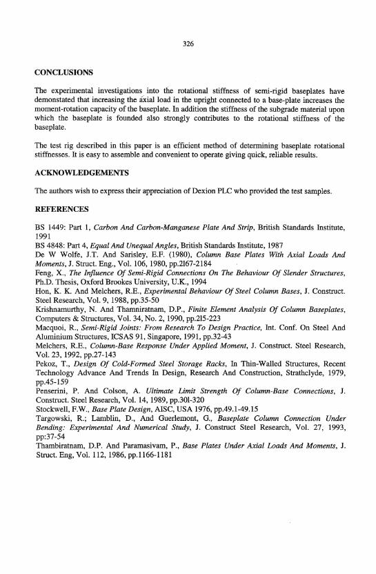
Figure I shows a schematic of the rig with a test panel located in it. It consisted of a 230kN servo-controlled hydraulic jack and a 100kN hand-controlled hydraulic jack located in a reaction frame. The rig is mounted horizontally. Figure 2 shows the loading applied to the test specimens. The side loading produces bending in the test rig. The test panel was located between spherical bearings at either end. To make the testing arrangement coincide with practical conditions, fullscale baseplates and sections of upright were used in the test panel. Torsional effects were eliminated by testing four baseplates and uprights simultaneously in an axisymmetric arrangement. As many columns used in the storage industry are "lightly" fixed to the ground the experiments reported were conducted without tightening the bolts locating the baseplates onto the subgrade block so that no tension was developed in these bolts which served mainly to locate the specimen.
Theoretical studies undel1aken by Feng, X. (1994) showed that different foundation subgrade reactions had effects upon baseplate performance. To enable these effects to be studied experimentally, timber and concrete blocks were placed in the middle of the test panel as they have significantly different moduli. Blocks can be constructed to have different reaction moduli.
EXPERIMENTAL ASSEMBLY
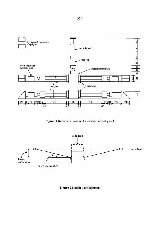
The baseplate assembly is shown in Figure 3 and consists of a flate plate approximately 200mm wide by 100mm deep by 4.5mm thick with an angle cleat welded onto it. Two 14mm diameter holes, 146mm apart, 21mmfrom the plate edges and 25mm from the back were drilled into each baseplate so that the plates could be located in the test rig. In the angle cleat there were two further holes 11.7mm diameter, 50mm apart and 25mm from the plate surface. These second holes were to enable the upright to be connected to the base plate.
The baseplate was made from steel grade HR43/35 or HR46/40 to BS 1449:Part I and the angle cleat to BS 4848: Part 4. The baseplates were degreased and stove enamelled.
The uprights were made from steel grade HRl4 to BS1449: Part 1 Cold-Reduced To Enhance Mechanical Properties and are shown in Figure 4.
The blocks used to provide the foundation sub grade were cubes 400mm x 400mm x 400mm and were made from either timber or concrete. Four 12mm diameter bolts were fixed in the face of

325
each block which was in contact with the baseplates. The bolts were 127mm from each side as shown in Figure 5 and were used to provide a location but not fixing for the baseplates. The Young's moduli of elasticity of the concrete and timber were determined experimentally to be 21468.8N/mm2 and 182.36N/mm2 respectively. These produced equivalent subgrade reaction moduli of 107.344N/mm3 and O.9118N/mm3 respectively. Appendix 2 shows the calculation of the modulus of the sub grade reactions.
LOADING AND TEST PROCEDURE
A constant axial load through the uprights was applied onto the base plates by the servocontrolled hydraulic jack loaded onto one end of the test panel, as shown in Figure 1.
A hand controlled jack was used to apply a lateral load on the side of each sub grade block. This load produced an increasing bending moment on the baseplates. The loads applied to the test panel were measured using load cells at the positions shown in Figure 1.
A plastic sheet was fitted between the sub grade block and the reaction frame to minimise frictional effects in the test rig.
Three pairs of displacement transducers were used during the test to measure the lateral displacement and monitor the rotation of the subgrade block. Their positions are shown in Figure 6. All readings were recorded on a data logger.
During the test, the axial load was applied first. After it had reached the required magnitude, the servo-controlled jack kept it constant throughout the test, while the lateral load was applied gradually by use of the hand-controlled jack until the ultimate bending moment was achieved. When the loading procedure was completed, the lateral load was removed first to keep the test panel stable. All readings were made automatically every five seconds.
TEST RESULTS
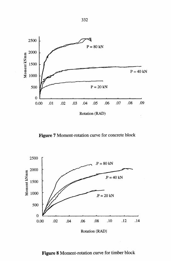
Two different test panels were chosen for the test to investigate the effects of sub grade reaction. One had a timber block subgrade and the other a concrete block subgrade. Three tests were carried out for each of the test panels under axial loads of 20kN, 40kN and 80kN.
Figures 7 and 8 show the effects of the different axial loads on the concrete and timber sub grades respectively. For both sub grades the initial slopes of the moment-rotation curves are the same but the ultimate moment-rotation capacity of the baseplates is increased when the axial load in the upright is increased.
Figures 9, 10 and 11 show the effects of different moduli of subgrade reaction. As indicated in these plots a concrete subgrade is much stiffer than a timber sub grade but interestingly the concrete subgrade does not always produce the maximum moment-rotation capacity.
326
CONCLUSIONS
The experimental investigations into the rotational stiffness of semi-rigid baseplates have demonstated that increasing the axial load in the upright connected to a base-plate increases the moment-rotation capacity of the baseplate. In addition the stiffness of the subgrade material upon which the baseplate is founded also strongly contributes to the rotational stiffness of the baseplate.
The test rig described in this paper is an efficient method of determining baseplate rotational stiffnesses. It is easy to assemble and convenient to operate giving quick, reliable results.
ACKNOWLEDGEMENTS
The authors wish to express their appreciation of Dexion PLC who provided the test samples.
REFERENCES
BS 1449: Part 1, Carbon And Carbon-Manganese Plate And Strip, British Standards Institute, 1991 BS 4848: Part 4, Equal And Unequal Angles, British Standards Institute, 1987 De W Wolfe, J.T. And Sarisley, E.F. (1980), Column Base Plates With Axial Loads And Moments, J. Struct. Eng., Vol. 106, 1980, pp.2167-2184 Feng, X., The Influence Of Semi-Rigid Connections On The Behaviour Of Slender Structures, Ph.D. Thesis, Oxford Brookes University, U.K., 1994 Hon, K. K. And Me1chers, R.E., Experimental Behaviour Of Steel Column Bases, J. Construct. Steel Research, Vol. 9, 1988, pp.35-50 Krishnamurthy, N. And Tharnniratnam, D.P., Finite Element Analysis Of Column Baseplates, Computers & Structures, Vol. 34, No.2, 1990, pp.215-223 Macquoi, R., Semi-Rigid Joints: From Research To Design Practice, Int. Conf. On Steel And Aluminium Structures, ICSAS 91, Singapore, 1991, pp.32-43 Me1chers, R.E., Column-Base Response Under Applied Moment, J. Construct. Steel Research, Vol. 23, 1992, pp.27-143 Pekoz, T., Design Of Cold-Formed Steel Storage Racks, In Thin-Walled Structures, Recent Technology Advance And Trends In Design, Research And Construction, Strathc1yde, 1979, pp.45-159 Penserini, P. And Colson, A. Ultimate Limit Strength Of Column-Base Connections, J. Construct. Steel Research, Vol. 14, 1989, pp.301-320 Stockwell, F.W., Base Plate Design, AISC, USA 1976, pp.49.1-49.15 Targowski, R.; Lamblin, D., And Guerlemont, G., Baseplate Column Connection Under Bending: Experimental And Numerical Study, J. Construct Steel Research, Vol. 27, 1993, pp:37-54 Thambiratnam, D.P. And Paramasivam, P., Base Plates Under Axial Loads And Moments, J. Struct. Eng, Vol. 112,1986, pp.1166-1181

327
APPENDIX 1 Notation
A cross-section area of block E Young's modulus of elasticity F Force acting on subgrade block K modulus of sub grade reaction ~ deformation
APPENDIX 2 Determination of the modulus of subgrade reaction
By definition, the modulus of subgrade reaction, k, is the reaction per unit area of foundation per unit deflection. Thus, the modulus can be written as '
k=~ At,.
where F is the force acting on both sides of the block, A, the area of the cross-section of the block and ~ the deformation defined by
FL ~=
AE
where L is the length of half the block (due to force F acting symmetrically on both ends of the block (see Figure 12).
Eliminating ~ between the equations gives the formula for the subgrade reaction as
k=~ L
By use of a compression test on a rectangular block Young's modulus of elasticity of the concrete was determined to be 21468.8N/mm2• This implies that the modulus of subgrade reaction for concrete in the tests described above was
k = 21468.8 = 107.344N Imm3
200
Similarly the modulus of the subgrade reaction for timber was 0.9118N/mm3•
328
U Section A-A orientation n of uprights
lateral deflection
foundatiol1 subgrade
uprights
600
4.5 4.5 4.5 4.5
Figure 1 Schematic plan and elevation of test panel
side load
1_1 __ . ~ 1
-----------~ ~-----------
baseplate rotation
Figure 2 Loading arrangement
0
~
'" ~
~ N
M
'" ~ ~ ~ N
I
f---- axial load
Baseplate
M lO ~rade 8 nuts
329
Upright
o
MlO x 19mm long ~ ~rade 8.8 bolts
£i
Figure 3 Baseplate assembly

330
4- 4-4- 4-4- 4-4- 4-
Holes 10.4<1>
4- 4-4-
Ie 103
·1 Front face
j.ill..I ...L:g -r..;
i. 2S I i
I.
I i i i i i i i i
Ii -,
: 103 .1
. ht dimepsions Figure 4 Upng
4-4-4-4-
Ie 53 ·1
Flange

331
400
/ /
/ locating bolts
I· 121 -I' l!I6 .1. 121 .1
Figure 5 Subgrade block showing locating bolts
T = transducer
TT TT
T T
Figure 6 Displacement transducer positions
2500
S 2000 S ~ 1500 = 4)
S o ~ 1000
500
332
P= 80kN
P=40kN
P=20kN
o ~--~--~~~~--~--~--~~--~~ 0.00 .01 .02 .03 .04 .05 .06 .07 .08 .09
Rotation (RAO)
Figure 7 Moment-rotation curve for concrete block
2500 .P= 80kN
S 2000 S ~ 1500 =
.P=40kN
4)
S 0
~ 1000 .P=20kN
500
0 0.00 .02 .04 .06 .08 .10 .12 .14
Rotation (RAO)
Figure 8 Moment-rotation curve for timber block

2500
8 2000 8 ~ "E 1500 ., 8 ~ 1000
500
o 0.00 .01
333
Timber block
.02 .03 .04 .05 .06 .07 .08
Rotation (RAD)
Figure 9 Moment-rotation curve for axial load of 80 kN
2500
8 2000 8 ~
1500 "E ., 8 o
;:;s 1000
500
o 0.00
Timber block
.01 .03 .04 .06 .07
Rotation (RAD)
Figure 10 Moment-rotation curve for axial load of 40 kN

2500
El 2000 El ~ d 1500 d)
El o
:::?J 1000
500
00.00
334
.Concrete block
Timber block
.02 .04 .06 .08 .10
Rotation (RAD)
Figure 11 Moment-rotation curve for axial load of 20 kN
F
F
Figure 12 Block subjected to compressive force