ROTARY CUTTER - Woods Equipment Company · operator' s m a rotary cutter nual (4/16/2014) rc3.5 rc4...
48
OPERATOR'S MANUAL ROTARY CUTTER (4/16/2014) RC3.5 RC4 RC5 RC6 MAN1048
Transcript of ROTARY CUTTER - Woods Equipment Company · operator' s m a rotary cutter nual (4/16/2014) rc3.5 rc4...

OP
ER
AT
OR
'S M
AN
UA
L
ROTARY CUTTER(4
/16
/201
4)
RC3.5RC4RC5RC6
MA
N10
48

2 Introduction Gen’l (Rev. 2/25/2016)
TO THE DEALER:
Assembly and proper installation of this product is the responsibility of the Woods® dealer. Read manual instructionsand safety rules. Make sure all items on the Dealer’s Pre-Delivery and Delivery Check Lists in the Operator’s Manualare completed before releasing equipment to the owner.
The dealer must complete the online Product Registration form at the Woods Dealer Website which certifies thatall Dealer Check List items have been completed. Dealers can register all Woods product atdealer.WoodsEquipment.com under Product Registration.
Failure to register the product does not diminish customer’s warranty rights.
TO THE OWNER:
Read this manual before operating your Woods equipment. The information presented will prepare you to do a better andsafer job. Keep this manual handy for ready reference. Require all operators to read this manual carefully and becomeacquainted with all adjustment and operating procedures before attempting to operate. Replacement manuals can beobtained from your dealer. To locate your nearest dealer, check the Dealer Locator at www.WoodsEquipment.com, or inthe United States and Canada call 1-800-319-6637.
The equipment you have purchased has been carefully engineered and manufactured to provide dependable andsatisfactory use. Like all mechanical products, it will require cleaning and upkeep. Lubricate the unit as specified.Observe all safety information in this manual and safety decals on the equipment.
For service, your authorized Woods dealer has trained mechanics, genuine Woods service parts, and the necessarytools and equipment to handle all your needs.
Use only genuine Woods service parts. Substitute parts will void the warranty and may not meet standards required forsafe and satisfactory operation. Record the model number and serial number of your equipment in the spacesprovided:
Model: _______________________________ Date of Purchase: _____________________
Serial Number: (see Safety Decal section for location) ____________________________________
Provide this information to your dealer to obtain correct repair parts.
Throughout this manual, the term NOTICE is used to indicate that failure to observe can cause damage to equipment.The terms CAUTION, WARNING, and DANGER are used in conjunction with the Safety-Alert Symbol (a triangle withan exclamation mark) to indicate the degree of hazard for items of personal safety.

Introduction 3MAN1048 (4/16/2014)
TABLE OF CONTENTSINTRODUCTION2
SPECIFICATIONS4
GENERAL INFORMATION4
ONLINE SAFETY VIDEO5
SAFETY RULES7-9
SAFETY DECALS10-11
OPERATION12
OWNER SERVICE17
TROUBLE SHOOTING21
DEALER SERVICE22
DEALER CHECK LISTS28
ASSEMBLY INSTRUCTIONS30
INDEX TO PARTS LISTS35
BOLT TORQUE CHART43
BOLT SIZE CHART & ABBRE-VIATIONS44
INDEX45
REPLACEMENT PARTS WAR-RANTY46
PRODUCT WARRANTYINSIDEBACK COVER
Si no lee Ingles, pida ayuda a alguien que si lo lee para que le
traduzca las medidas de seguridad.
LEA EL INSTRUCTIVO!!
4 Introduction MAN1048 (4/16/2014)
SPECIFICATIONS
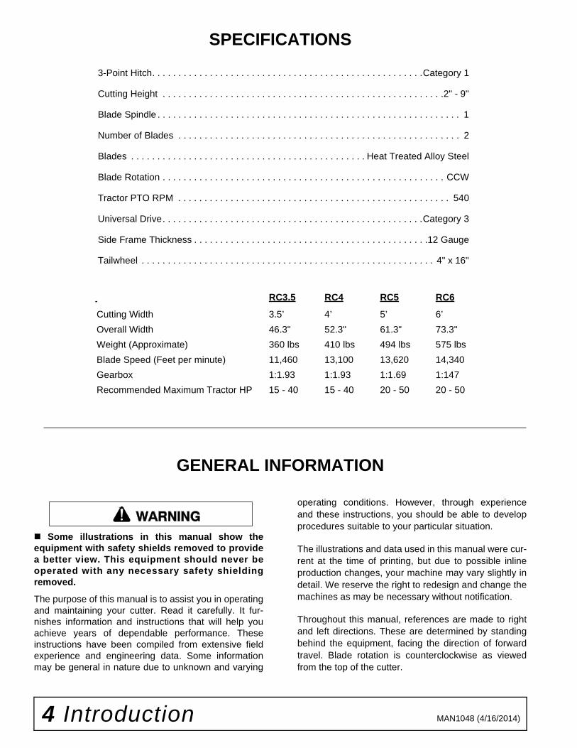
3-Point Hitch. . . . . . . . . . . . . . . . . . . . . . . . . . . . . . . . . . . . . . . . . . . . . . . . . . . .Category 1
Cutting Height . . . . . . . . . . . . . . . . . . . . . . . . . . . . . . . . . . . . . . . . . . . . . . . . . . . . . .2" - 9"
Blade Spindle . . . . . . . . . . . . . . . . . . . . . . . . . . . . . . . . . . . . . . . . . . . . . . . . . . . . . . . . . . 1
Number of Blades . . . . . . . . . . . . . . . . . . . . . . . . . . . . . . . . . . . . . . . . . . . . . . . . . . . . . . 2
Blades . . . . . . . . . . . . . . . . . . . . . . . . . . . . . . . . . . . . . . . . . . . . . Heat Treated Alloy Steel
Blade Rotation . . . . . . . . . . . . . . . . . . . . . . . . . . . . . . . . . . . . . . . . . . . . . . . . . . . . . . CCW
Tractor PTO RPM . . . . . . . . . . . . . . . . . . . . . . . . . . . . . . . . . . . . . . . . . . . . . . . . . . . . 540
Universal Drive. . . . . . . . . . . . . . . . . . . . . . . . . . . . . . . . . . . . . . . . . . . . . . . . . .Category 3
Side Frame Thickness . . . . . . . . . . . . . . . . . . . . . . . . . . . . . . . . . . . . . . . . . . . . .12 Gauge
Tailwheel . . . . . . . . . . . . . . . . . . . . . . . . . . . . . . . . . . . . . . . . . . . . . . . . . . . . . . . . 4" x 16"
GENERAL INFORMATION
Some illustrations in this manual show theequipment with safety shields removed to providea better view. This equipment should never beoperated with any necessary safety shieldingremoved.
The purpose of this manual is to assist you in operatingand maintaining your cutter. Read it carefully. It fur-nishes information and instructions that will help youachieve years of dependable performance. Theseinstructions have been compiled from extensive fieldexperience and engineering data. Some informationmay be general in nature due to unknown and varying
operating conditions. However, through experienceand these instructions, you should be able to developprocedures suitable to your particular situation.
The illustrations and data used in this manual were cur-rent at the time of printing, but due to possible inlineproduction changes, your machine may vary slightly indetail. We reserve the right to redesign and change themachines as may be necessary without notification.
Throughout this manual, references are made to rightand left directions. These are determined by standingbehind the equipment, facing the direction of forwardtravel. Blade rotation is counterclockwise as viewedfrom the top of the cutter.
RC3.5 RC4 RC5 RC6
Cutting Width 3.5’ 4’ 5’ 6’
Overall Width 46.3" 52.3" 61.3" 73.3"
Weight (Approximate) 360 lbs 410 lbs 494 lbs 575 lbs
Blade Speed (Feet per minute) 11,460 13,100 13,620 14,340
Gearbox 1:1.93 1:1.93 1:1.69 1:147
Recommended Maximum Tractor HP 15 - 40 15 - 40 20 - 50 20 - 50
�������

Safety 5Safety Video Online Form (Rev. 1/09/2018)
Watch a Mower Safety Video OnlineThe AEM (Association of Equipment Manufacturers) offers a safety training video, Industrial and Agricultural Mower Safety Practices. The 22-minute video can be viewed online for free at TheAEMStore,
https://youtu.be/uEWXsDqhDq0
It reinforces the proper procedures to follow while operating your mowing equipment. The video does not replace the information contained in the Operator’s Manual, so please review this manual thoroughly before operating your new mowing equipment.
Safety Training Does Make a Difference.
BE SAFE!
BE ALERT!
BE ALIVE!
BE TRAINED Before Operating Mowers!
ASSOCIATION OF EQUIPMENT MANUFACTURERS
Safety Video Order Form

6 Safety Safety Video Online Form (Rev. 1/09/2018)
Also, available from the Association of Equipment Manufacturers:
A large variety of training materials (ideal for groups) are available for a nominal charge from AEM. Following is a partial list:
● Training Package for Rotary Mowers/Cutters-English Contains: DVD & VHS (English)
Guidebook for Rotary Mowers/Cutters (English)AEM Industrial/Agricultural Mower Safety Manual (English)AEM Agricultural Tractor Safety Manual (English)
● Training Package for Rotary Mowers/Cutters-English/Spanish Contains: DVD & VHS (English/Spanish)
Guidebook for Rotary Mowers/Cutters (English/Spanish)AEM Industrial/Agricultural Mower Safety Manual (English/Spanish)AEM Agricultural Tractor Safety Manual (English/Spanish)
AEM training packages are available through:
AEM at: www.aem.orgorUniversal Lithographers, Inc.Email: [email protected] tel866-541-1668 fax

Safety 7Single Spindle Cutter LD/MD (Rev. 10/27/2006)
TRAINING
Safety instructions are important! Read allattachment and power unit manuals; follow allsafety rules and safety decal information. (Replace-ment manuals and safety decals are available fromyour dealer. To locate your nearest dealer, checkthe Dealer Locator at www.WoodsEquipment.com,or in the United States and Canada call 1-800-319-6637.) Failure to follow instructions or safety rulescan result in serious injury or death.
If you do not understand any part of this manualand need assistance, see your dealer.
Know your controls and how to stop engine andattachment quickly in an emergency.
Operators must be instructed in and be capableof the safe operation of the equipment, its attach-ments, and all controls. Do not allow anyone tooperate this equipment without proper instruc-tions.
Never allow children or untrained persons tooperate equipment.
PREPARATION
Check that all hardware is properly installed.Always tighten to torque chart specificationsunless instructed otherwise in this manual.
Always wear relatively tight and belted clothingto avoid getting caught in moving parts. Wearsturdy, rough-soled work shoes and protectiveequipment for eyes, hair, hands, hearing, and head;and respirator or filter mask where appropriate.
Make sure attachment is properly secured,adjusted, and in good operating condition.
Make sure spring-activated locking pin or collarslides freely and is seated firmly in tractor PTOspline groove.
Connect PTO driveline directly to power unitPTO shaft. Never use adapter sleeves or adaptershafts. Adapters can cause driveline failures due toincorrect spline or incorrect operating length andcan result in personal injury or death.
Before starting power unit, check all equipmentdriveline guards for damage. Replace any damagedguards. Make sure all guards rotate freely on alldrivelines. If guards do not rotate freely on drive-lines, repair and replace bearings before puttingequipment into service.
Power unit must be equipped with ROPS orROPS cab and seat belt. Keep seat belt securelyfastened. Falling off power unit can result in deathfrom being run over or crushed. Keep foldableROPS system in “locked up” position at all times.
Inspect chain, rubber, or steel band shieldingbefore each use. Replace if damaged.
Remove accumulated debris from this equip-ment, power unit, and engine to avoid fire hazard.
Make sure all safety decals are installed.Replace if damaged. (See Safety Decals section forlocation.)
Make sure shields and guards are properlyinstalled and in good condition. Replace if dam-aged.
A minimum 20% of tractor and equipmentweight must be on the tractor front wheels whenattachments are in transport position. Without thisweight, front tractor wheels could raise up result-ing in loss of steering. The weight may be attainedwith front wheel weights, ballast in tires, front trac-tor weights or front loader. Weigh the tractor andequipment. Do not estimate.
Inspect and clear area of stones, branches, orother hard objects that might be thrown, causinginjury or damage.
OPERATION
Do not allow bystanders in the area when oper-ating, attaching, removing, assembling, or servic-ing equipment.
Full chain, rubber, or steel band shielding mustbe installed when operating in populated areas orother areas where thrown objects could injure peo-ple or damage property.
Safety is a primary concern in the design andmanufacture of our products. Unfortunately, ourefforts to provide safe equipment can be wipedout by an operator’s single careless act.
In addition to the design and configuration ofequipment, hazard control and accident preven-tion are dependent upon the awareness, con-cern, judgement, and proper training ofpersonnel involved in the operation, transport,maintenance, and storage of equipment.
It has been said, “The best safety device is aninformed, careful operator.” We ask you to bethat kind of operator.
SAFETY RULESATTENTION! BECOME ALERT! YOUR SAFETY IS INVOLVED!

8 Safety Single Spindle Cutter LD/MD (Rev. 10/27/2006)
• If this machine is not equipped with full chain,rubber, or steel band shielding, operation mustbe stopped when anyone comes within 300 feet(92 m).• This shielding is designed to reduce the riskof thrown objects. The mower deck and protec-tive devices cannot prevent all objects fromescaping the blade enclosure in every mowingcondition. It is possible for objects to ricochetand escape, traveling as much as 300 feet (92 m).
Never direct discharge toward people, animals,or property.
Do not operate or transport equipment whileunder the influence of alcohol or drugs.
Operate only in daylight or good artificial light.
Keep hands, feet, hair, and clothing away fromequipment while engine is running. Stay clear of allmoving parts.
Always comply with all state and local lightingand marking requirements.
Never allow riders on power unit or attachment.
Power unit must be equipped with ROPS orROPS cab and seat belt. Keep seat belt securelyfastened. Falling off power unit can result in deathfrom being run over or crushed. Keep foldableROPS system in “locked up” position at all times.
Always sit in power unit seat when operatingcontrols or starting engine. Securely fasten seatbelt, place transmission in neutral, engage brake,and ensure all other controls are disengagedbefore starting power unit engine.
Operate tractor PTO at 540 RPM. Do not exceed.
Do not operate PTO during transport.
Look down and to the rear and make sure areais clear before operating in reverse.
Do not operate or transport on steep slopes.
Do not stop, start, or change directions sud-denly on slopes.
Use extreme care and reduce ground speed onslopes and rough terrain.
Watch for hidden hazards on the terrain duringoperation.
Stop power unit and equipment immediatelyupon striking an obstruction. Turn off engine,remove key, inspect, and repair any damage beforeresuming operation.
Leak down or failure of mechanical or hydraulicsystem can cause equipment to drop.
Before performing any service or maintenance,disconnect driveline from tractor PTO.
MAINTENANCE
Before performing any service or maintenance,disconnect driveline from tractor PTO.
Before working underneath, disconnect drive-line, raise cutter, and block cutter securely. Hydrau-lic system leak down and failure of mechanical orhydraulic system can cause equipment to drop.
Do not modify or alter or permit anyone else tomodify or alter the equipment or any of its compo-nents in any way.
Always wear relatively tight and belted clothingto avoid getting caught in moving parts. Wearsturdy, rough-soled work shoes and protectiveequipment for eyes, hair, hands, hearing, and head;and respirator or filter mask where appropriate.
Make sure attachment is properly secured,adjusted, and in good operating condition.
Do not allow bystanders in the area when oper-ating, attaching, removing, assembling, or servic-ing equipment.
Keep all persons away from operator controlarea while performing adjustments, service, ormaintenance.
Make certain all movement of equipment com-ponents has stopped before approaching for ser-vice.
Frequently check blades. They should be sharp,free of nicks and cracks, and securely fastened.
Do not handle blades with bare hands. Carelessor improper handling may result in serious injury.
Your dealer can supply genuine replacementblades. Substitute blades may not meet originalequipment specifications and may be dangerous.
Tighten all bolts, nuts, and screws to torquechart specifications. Check that all cotter pins areinstalled securely to ensure equipment is in a safecondition before putting unit into service.
Make sure all safety decals are installed.Replace if damaged. (See Safety Decals section forlocation.)
Make sure shields and guards are properlyinstalled and in good condition. Replace if dam-aged.
SAFETY RULESATTENTION! BECOME ALERT! YOUR SAFETY IS INVOLVED!

Safety 9Single Spindle Cutter LD/MD (Rev. 10/27/2006)
STORAGE
Keep children and bystanders away from stor-age area.
Disconnect cutter driveshaft and secure up offground. Raise cutter with 3-point hitch. Place
blocks under cutter side skids. Lower cutter ontoblocks. Disconnect cutter from tractor 3-point hitchand carefully drive tractor away from cutter.
SAFETY RULESATTENTION! BECOME ALERT! YOUR SAFETY IS INVOLVED!

10 Safety MAN1048 (4/16/2014)
SERIAL NUMBER PLATE - PN 1033176
ROTATING BLADES AND THROWN OBJECTS
� Do not put hands or feet under or into mower when engine is running.
� Before mowing, clear area of objects that may be thrown by blade.
� Keep bystanders away.
� Keep guards in place and in good condition.
BLADE CONTACT OR THROWN OBJECTS CAN CAUSE SERIOUS INJURY OR DEATH.
DANGER
ROTATING DRIVELINE
CONTACT CAN CAUSE DEATH
KEEP AWAY!
DO NOT OPERATE WITHOUT -
� All driveline guards, tractor and equipment shields in place
� Drivelines securely attached at both ends
� Driveline guards that turn freely on driveline
1006682-A
DANGER
PN 1006682
PN 20106RED REAR REFLECTOR 4.5"
SAFETY & INSTRUCTIONAL DECALSATTENTION! BECOME ALERT! YOUR SAFETY IS INVOLVED!
Replace Immediately If Damaged!

Safety 11MAN1048 (4/16/2014)
PN 1004114
PN 33347
����� ������
�� �� � �����
�����
33347E
�����
�����
����� ������
�� �� � �����
CRUSHING AND PINCHING HAZARD
� Be extremely careful handling various parts of the machine. They are heavy and hands, fingers, feet, and other body parts could be crushed or pinched between tractor and implement.
� Operate tractor controls from tractor seat only.
� Do not stand between tractor and implement when tractor is in gear.
� Make sure parking brake is engaged before going between tractor and implement.
� Stand clear of machine while in operation or when it is being raised or lowered.
FAILURE TO FOLLOW THESE INSTRUCTIONS COULD RESULT IN SERIOUS INJURY OR DEATH.
WARNING
TO AVOID SERIOUS INJURY OR DEATH:
� Read Operator's Manual (available from dealer) and follow all safety precautions.
� Keep all shields in place and in good condition.
� Operate mower from tractor seat only.
� Lower mower, stop engine and remove key before dismounting tractor.
� Allow no children or untrained persons to operate equipment.
� Do not transport towed or semi-mounted units over 20 mph.
FAILURE TO OPERATE SAFELY CAN RESULT IN INJURY OR DEATH.
WARNING
WARNING
FALLING OFF CAN RESULT IN BEING RUN OVER.
� Tractor must be equipped with ROPS (or ROPS CAB) and seat belt. Keep foldable ROPS systems in "locked up" position at all times.
� Buckle Up! Keep seat belt securely fastened.
� Allow no riders.
RAISED EQUIPMENT CAN DROP AND CRUSH.
� Before working underneath, follow all instructions and safety rules in operator's manual and securely block up all corners of equipment with jack stands.
� Securely blocking prevents equipment from dropping from hydraulic leakdown, hydraulic system failures or mechanical component failures.
FALLING OFF OR FAILING TO BLOCK SECURELY CAN RESULT IN SERIOUS INJURY OR DEATH.
1006681
WARNINGDO NOT EXCEED PTO SPEED OF
540 RPMPTO speeds higher than 540 RPM can cause
equipment failure and personal injury.
PN 1006681
BE CAREFUL!
Use a clean, damp cloth to clean safety decals.
Avoid spraying too close to decals when using a pressure washer; high-pressure water can enter through very small scratches or under edges of decals causing them to peel or come off.
Replacement safety decals can be ordered free from your Woods dealer. To locate your nearest dealer, check the Dealer Locator at www.WoodsEquipment.com, or in the United States and Canada call 1-800-319-6637.
If shaft connection is visible, shield is missing. Replace shield before operating equipment.
DANGNGERER
1004114
PN 18864
SAFETY & INSTRUCTIONAL DECALSATTENTION! BECOME ALERT! YOUR SAFETY IS INVOLVED!
Replace Immediately If Damaged!
12 Operation MAN1048 (4/16/2014)
OPERATION
The operator is responsible for the safe operation ofthe cutter. The operator must be properly trained.Operators should be familiar with the cutter, the tractor,and all safety practices before starting operation. Readthe safety rules and safety decals on page 7 throughpage 11.
This standard-duty cutter is designed for grass andweed mowing and shredding.
Recommended mowing speed for most conditions isfrom 2 to 5 mph.
Full chain, rubber, or steel band shielding mustbe installed when operating in populated areas orother areas where thrown objects could injure peo-ple or damage property.
• If this machine is not equipped with full chain,rubber, or steel band shielding, operation mustbe stopped when anyone comes within 300 feet(92 m).• This shielding is designed to reduce the riskof thrown objects. The mower deck and protec-tive devices cannot prevent all objects fromescaping the blade enclosure in every mowingcondition. It is possible for objects to ricochetand escape, traveling as much as 300 feet (92 m).
Never allow riders on power unit or attachment.
Keep bystanders away from equipment.
Make sure spring-activated locking pin or collarslides freely and is seated firmly in tractor PTOspline groove.
Operate tractor PTO at 540 RPM. Do not exceed.
Stop power unit and equipment immediatelyupon striking an obstruction. Turn off engine, setparking brake, remove key, inspect, and repair anydamage before resuming operation.
Always wear relatively tight and belted clothingto avoid getting caught in moving parts. Wearsturdy, rough-soled work shoes and protectiveequipment for eyes, hair, hands, hearing, and head;and respirator or filter mask where appropriate.
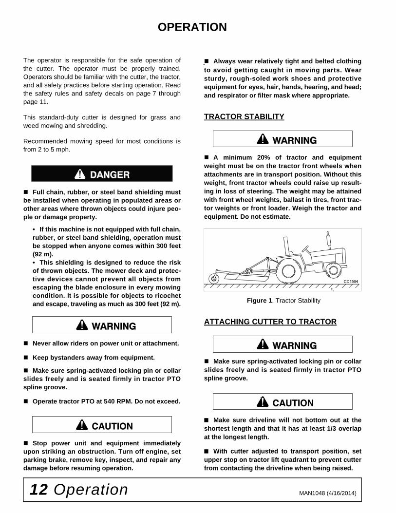
TRACTOR STABILITY
A minimum 20% of tractor and equipmentweight must be on the tractor front wheels whenattachments are in transport position. Without thisweight, front tractor wheels could raise up result-ing in loss of steering. The weight may be attainedwith front wheel weights, ballast in tires, front trac-tor weights or front loader. Weigh the tractor andequipment. Do not estimate.
Figure 1. Tractor Stability
ATTACHING CUTTER TO TRACTOR
Make sure spring-activated locking pin or collarslides freely and is seated firmly in tractor PTOspline groove.
■ Make sure driveline will not bottom out at theshortest length and that it has at least 1/3 overlapat the longest length.
■ With cutter adjusted to transport position, setupper stop on tractor lift quadrant to prevent cutterfrom contacting the driveline when being raised.
������
�������
CAUTION
�������
�������
CAUTION

Operation 13MAN1048 (4/16/2014)
Figure 2. Standard Hitch and Quick Hitch Configurations
Standard Hitch (See Figure 2)
1. Position tractor 3-point arms over the hitch pinsand secure.
2. Connect the tractor top link to the cutter A-frameusing the upper holes and the appropriatehardware. The break link must be placed in thelower holes of the A-frame.
3. For subcompact tractors, it may be necessary toposition the break link pivot in the front location.
Quick Hitch
1. Break link pivot must be located in rear location.
2. Install quick hitch sleeves over hitch pins andsecure with Klik pin.
3. Attach tractor with the quick hitch to the cutter andsecure according to the quick hitch manufacturer’sinstuctions.
INSTALLATION AND REMOVAL OF DRIVELINE (TRACTOR PTO)
To Install:
Pull locking collar back and at the same time pushdriveline onto tractor PTO shaft until locking deviceengages.
To Remove:
Hold driveline into position, pull locking collar back, andslide driveline off tractor PTO shaft.
Figure 3. Lock Collar
DRIVELINE ATTACHMENT
Attach the cutter to the tractor 3-point hitch (or quickhitch if available). Do not attach driveline. Raise andlower cutter to determine maximum and minimum dis-tance between the tractor PTO shaft and the gearboxinput shaft. If the distance is too large, the driveline willbe too short for proper engagement. If distance is toosmall, the driveline may bottom out in operation anddamage the cutter or tractor.
The driveline length must be sufficient to provide atleast 1/3 driveline length of engagement during opera-tion. There must be at least 4 inches of engagement atthe cutter’s lowest possible point of operation. Thedriveline must not bottom out when raised to the maxi-mum height possible.
If driveline is too short, please call your Woods dealerfor a longer driveline.
If driveline is too long, please follow the instructions forshortening the driveline.

14 Operation MAN1048 (4/16/2014)
SHORTENING DRIVELINE
1. Move cutter up and down to get the shortestpossible distance between tractor PTO shaft andgearbox input shaft.
2. Separate driveline into two halves and connectthem to the tractor PTO and gearbox.
3. Place driveline halves parallel to one another todetermine how much to shorten the driveline.
Figure 4. Drive Halves Placed Parallel
4. Measure from end of the upper shield to the baseof the bell on the lower shield (A). Add 1-9/16" todimension (A). See Figure 5.
Figure 5. Determine Shield Length
5. Cut the shield to the overall dimension.
Figure 6. Cut Shield
6. Place the cutoff portion of the shield against theend of the shaft and use as a guide. Mark and cutthe shaft.
Figure 7. Cut Shaft to Length
7. Repeat step 6 for the other half of the drive.
8. File and clean cut ends of both drive halves.
Do not use tractor if proper driveline engagement can-not be obtained through these methods.
Connect driveline to tractor PTO shaft, making sure thespring-activated locking collar slides freely and locksdriveline to PTO shaft.
NOTICE■ If attaching with quick hitch, the distancebetween the tractor PTO and gearbox input shaftwill increase. Please follow the steps as you wouldfor a 3-point hitch to insure proper engagement.
DP2
1-9/16"
A
DP3
DP4
DP5

Operation 15MAN1048 (4/16/2014)
DRIVELINE INTERFERENCE CHECK
1. Check for clearance between driveline and cutterdeck.
2. Slowly lift cutter and observe driveline. If clearancebetween driveline and cutter deck is less than 1inch, shorten top link or limit upper travel of lowerhitch arms. Refer to tractor operator's manual forinstructions.
CUTTING HEIGHT ADJUSTMENT
Keep all persons away from operator controlarea while performing adjustments, service, ormaintenance.
■ Avoid low cutting heights. Striking the groundwith blades produces one of the most damagingshock loads a cutter can encounter. Allowingblades to contact ground repeatedly will causedamage to cutter and drive.
1. Level cutter from side to side. Check by measuringfrom cutter frame to the ground at each side skid.
2. Adjust, using tractor 3-point arm leveling device.
NOTE: Keep the front of cutter slightly lower thanrear for best mowing.
3. Control cutting height with tractor 3-point arms,rear tailwheel adjustment.
4. To raise rear of cutter, move tailwheel arm down.
5. To raise front of cutter, raise tractor 3-point arms.
The cutting height is the distance between the bladeand the ground. The blades are approximately 1.25"above the side skid. To check cutting height, do the fol-lowing:
a) Select a cutting height; as an example, for anapproximate cutting height of 3", set the side skidabove the ground:
b) Adjust the front-to-rear attitude from 1/2" to 3/4"higher than the front.
6. Adjust top link to provide 1.2" of clearance betweenbreak link and rear lift arms. See Figure 8. Theclearance will allow cutter to float over uneventerrain.
SHREDDING MATERIAL
For shredding, set the cutter lower at rear. Determinehow much lower to set the rear by experimenting in dif-ferent situations.
Figure 8. Cutting Height Adjustment
������� 3" Desired cutting height- 1.25" Distance blade cutting edge is above side
skid= 1.75"

16 Operation MAN1048 (4/16/2014)
OPERATING TECHNIQUE
1. Power for operating the cutter is supplied by thetractor PTO. Operate PTO at 540 rpm. Know how
to stop the tractor and cutter quickly in an
emergency.
2. Engage PTO at a low engine rpm to minimize
stress on the drive system and gearbox. With PTO
engaged, raise PTO speed to 540 rpm andmaintain throughout cutting operation.
Gearbox protection is provided by a slip clutch withreplacement fiber disc or a shear bolt. The slip
clutch is designed to slip and the shear bolt will
shear when excessive torsion loads occur.
3. Move slowly into material. Adjust tractor ground
speed to provide a clean cut without lugging the
tractor engine. Use a slow ground speed for bettershredding.
Proper ground speed will depend on the terrain
and the material’s height, type, and density.
Normally, ground speed will range from 2 to 5 mph.Tall, dense material should be cut at a low speed;
thin, medium-height material can be cut at a faster
ground speed.
4. Always operate tractor PTO at 540 rpm to maintainproper blade speed and to produce a clean cut.
5. Under certain conditions tractor tires may roll down
some grass and prevent cutting at the same heightas the surrounding area. When this occurs, reduce
your ground speed but maintain PTO at 540 rpm.The lower ground speed will permit grass to
rebound partially.
STORAGE
Disconnect cutter driveshaft and secure up off
ground. Raise cutter with 3-point hitch. Place
blocks under cutter side skids. Lower cutter ontoblocks. Disconnect cutter from tractor 3-point hitch
and carefully drive tractor away from cutter.
Keep children and bystanders away from stor-age area.
PRE-OPERATION CHECK LISTOWNER’S RESPONSIBILITY
___ Review and follow all safety rules and safetydecal instructions on page 7 through page 11.
___ Check that equipment is properly and securelyattached to tractor.
___ Make sure driveline spring-activated locking pinor collar slides freely and is seated firmly in trac-tor PTO spline groove.
___ Set tractor PTO at 540 rpm.
___ Lubricate all grease fitting locations. Make surePTO shaft slip joint is lubricated.
___ Check to be sure gear lube runs out the smallcheck plug on side of gearbox.
___ Check that all hardware is properly installed andsecured.
___ Check that blades are sharp and secure and cut-ting edge is positioned to lead in a counterclock-wise rotation.
___ Check that shields and guards are properlyinstalled and in good condition. Replace if dam-aged.
___ Check cutting height, front-to-rear attitude, andtop link adjustment.
___ Place tractor PTO and transmission in neutralbefore starting engine.
___ Inspect area to be cut and remove stones,branches, or other hard objects that might bethrown and cause injury or damage.
�������

Owner Service 17MAN1048 (4/16/2014)
OWNER SERVICE
The information in this section is written for operatorswho possess basic mechanical skills. If you need help,your dealer has trained service technicians available.For your protection, read and follow the safety informa-tion in this manual
Keep all persons away from operator controlarea while performing adjustments, service, ormaintenance.
If you do not understand any part of this manualand need assistance, see your dealer.
Always wear relatively tight and belted clothingto avoid getting caught in moving parts. Wearsturdy, rough-soled work shoes and protectiveequipment for eyes, hair, hands, hearing, and head;and respirator or filter mask where appropriate.
BLOCKING METHOD
Before performing any service or maintenance,disconnect driveline from tractor PTO.
Never go underneath equipment (lowered to theground or raised) unless it is properly blocked andsecured. Never place any part of the body under-neath equipment or between moveable parts evenwhen the engine has been turned off. Hydraulicsystem leak down, hydraulic system failures,mechanical failures, or movement of control leverscan cause equipment to drop or rotate unexpect-edly and cause severe injury or death. Follow Oper-ator's Manual instructions for working underneathand blocking requirements or have work done by aqualified dealer.
To minimize the potential hazards of working under-neath the cutter, follow these procedures.
1. Jackstands with a load rating of 1000 lbs or moreare the only approved blocking device for thiscutter. Install a minimum of four jackstands (shownby Xs in Figure 9) under the cutter before workingunderneath unit.
Do not position jackstands under wheels, axles, orwheel supports. Components can rotate and causecutter to fall.
2. Consider the overall stability of the blocked unit.Just placing jackstands underneath will not ensureyour safety.
The working surface must be level and solid tosupport the weight on the jackstands. Make surejackstands are stable, both top and bottom. Makesure cutter is approximately level.
3. With full cutter weight lowered onto jackstands, testblocking stability before working underneath.
4. If cutter is attached to tractor when blocking, setthe brakes, remove key, and block cutter beforeworking underneath.
5. Securely block rear tractor wheels, in front andbehind. Tighten tractor lower 3-point arm anti-swaymechanism to prevent side-to-side movement.
LUBRICATION INFORMATION
1. Do not let excess grease collect on or aroundparts, particularly when operating in sandy areas.
2. See Figure 9 for lubrication points and frequency oflubrication based on normal operating conditions.Severe or unusual conditions may require morefrequent lubrication.
3. Use a lithium grease of #2 consistency with aMOLY (molybdenum disulfide) additive for alllocations unless otherwise noted. Be sure to cleanfittings thoroughly before attaching grease gun.One good pump of most guns is sufficient when thelubrication schedule is followed.
Gearbox Lubrication
1. For gearbox, use a high quality gear oil with aviscosity index of 80W or 90W and an API servicerating of GL-4 or -5 in gearboxes.
2. Fill gearbox until oil runs out the side plug ongearbox. Check gearbox daily for evidence ofleakage, and contact your dealer if leakage occurs.
Driveline Lubrication
1. Lubricate the driveline slip joint every eightoperating hours. Failure to maintain properlubrication could result in damage to U-joints,gearbox, and driveline.
2. Lower cutter to ground, disconnect driveline fromtractor PTO shaft, and slide halves apart but do notdisconnect from each other.
3. Apply a bead of grease completely around malehalf where it meets female half. Slide drive halvesover each other several times to distribute grease.
�������
CAUTION
�������
18 Owner Service MAN1048 (4/16/2014)
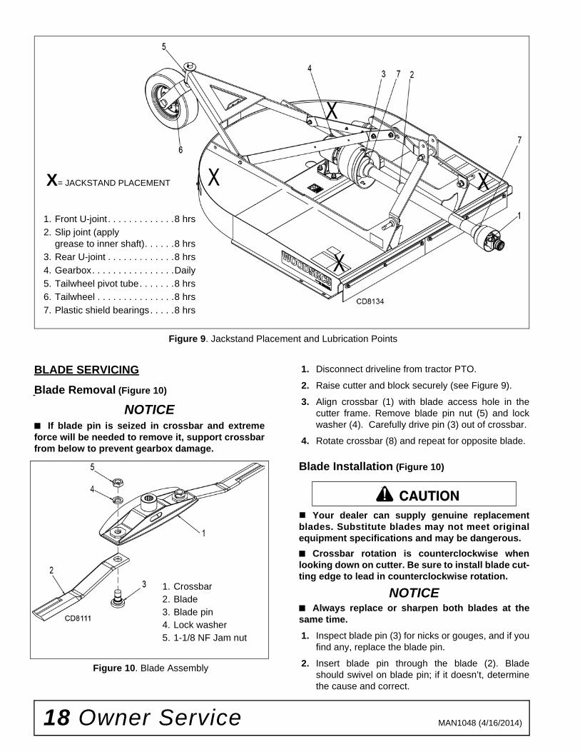
Figure 9. Jackstand Placement and Lubrication Points
BLADE SERVICING
Blade Removal (Figure 10)
NOTICE■ If blade pin is seized in crossbar and extremeforce will be needed to remove it, support crossbarfrom below to prevent gearbox damage.
Figure 10. Blade Assembly
1. Disconnect driveline from tractor PTO.
2. Raise cutter and block securely (see Figure 9).
3. Align crossbar (1) with blade access hole in thecutter frame. Remove blade pin nut (5) and lockwasher (4). Carefully drive pin (3) out of crossbar.
4. Rotate crossbar (8) and repeat for opposite blade.
Blade Installation (Figure 10)
Your dealer can supply genuine replacementblades. Substitute blades may not meet originalequipment specifications and may be dangerous.
■ Crossbar rotation is counterclockwise whenlooking down on cutter. Be sure to install blade cut-ting edge to lead in counterclockwise rotation.
NOTICE■ Always replace or sharpen both blades at thesame time.
1. Inspect blade pin (3) for nicks or gouges, and if youfind any, replace the blade pin.
2. Insert blade pin through the blade (2). Bladeshould swivel on blade pin; if it doesn’t, determinethe cause and correct.
X= JACKSTAND PLACEMENT
1. Front U-joint . . . . . . . . . . . . .8 hrs
2. Slip joint (applygrease to inner shaft). . . . . .8 hrs
3. Rear U-joint . . . . . . . . . . . . .8 hrs
4. Gearbox. . . . . . . . . . . . . . . .Daily
5. Tailwheel pivot tube. . . . . . .8 hrs
6. Tailwheel . . . . . . . . . . . . . . .8 hrs
7. Plastic shield bearings. . . . .8 hrs
1. Crossbar2. Blade3. Blade pin4. Lock washer5. 1-1/8 NF Jam nut
CAUTION
Owner Service 19MAN1048 (4/16/2014)
3. Align crossbar (1) with blade access hole in cutterframe. Apply a liberal coating of Never Seez® orequivalent to blade pin and crossbar hole. Makesure blade offset is away from cutter. Push bladepin through crossbar.
4. Insert lock washer (4) and nut (5) through bladeaccess hole in deck. Install on blade pin (3) andtighten to 450 lb-ft using a 1-11/16" socket.
NOTE: Blade should be snug but should swivel onpin without having to exert excessive force.
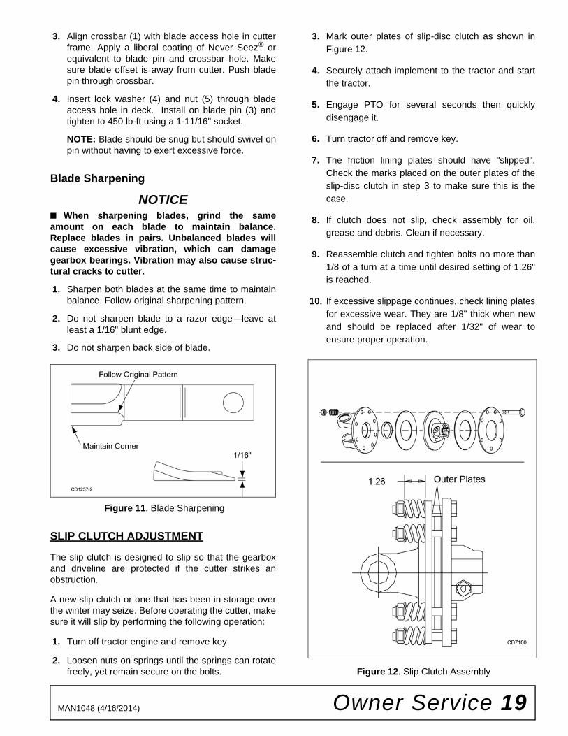
Blade Sharpening
NOTICE■ When sharpening blades, grind the sameamount on each blade to maintain balance.Replace blades in pairs. Unbalanced blades willcause excessive vibration, which can damagegearbox bearings. Vibration may also cause struc-tural cracks to cutter.
1. Sharpen both blades at the same time to maintainbalance. Follow original sharpening pattern.
2. Do not sharpen blade to a razor edge—leave atleast a 1/16" blunt edge.
3. Do not sharpen back side of blade.
Figure 11. Blade Sharpening
SLIP CLUTCH ADJUSTMENT
The slip clutch is designed to slip so that the gearboxand driveline are protected if the cutter strikes anobstruction.
A new slip clutch or one that has been in storage overthe winter may seize. Before operating the cutter, makesure it will slip by performing the following operation:
1. Turn off tractor engine and remove key.
2. Loosen nuts on springs until the springs can rotatefreely, yet remain secure on the bolts.
3. Mark outer plates of slip-disc clutch as shown inFigure 12.
4. Securely attach implement to the tractor and startthe tractor.
5. Engage PTO for several seconds then quicklydisengage it.
6. Turn tractor off and remove key.
7. The friction lining plates should have "slipped".Check the marks placed on the outer plates of theslip-disc clutch in step 3 to make sure this is thecase.
8. If clutch does not slip, check assembly for oil,grease and debris. Clean if necessary.
9. Reassemble clutch and tighten bolts no more than1/8 of a turn at a time until desired setting of 1.26"is reached.
10. If excessive slippage continues, check lining platesfor excessive wear. They are 1/8" thick when newand should be replaced after 1/32" of wear toensure proper operation.
Figure 12. Slip Clutch Assembly

20 Owner Service MAN1048 (4/16/2014)
DRIVELINE SHEAR BOLT REPLACEMENT
NOTICE
■ Always use approved 1/2" NC x 3" grade 2 shearbolt as a replacement part. Using a hardened boltor shear pin may result in damage to driveline orgearbox.
1. Remove damaged shear bolt (7).
2. Rotate driveline (6) to align holes in yoke and shaft.Install shear bolt and secure with lock nut (8).
Figure 13. Shear Bolt Driveline Assembly
SHIELDING REPAIR
Full chain, rubber, or steel band shielding mustbe installed when operating in populated areas orother areas where thrown objects could injure peo-ple or damage property.
• If this machine is not equipped with full chain,rubber, or steel band shielding, operation mustbe stopped when anyone comes within 300 feet(92 m).• This shielding is designed to reduce the riskof thrown objects. The mower deck and protec-tive devices cannot prevent all objects fromescaping the blade enclosure in every mowingcondition. It is possible for objects to ricochetand escape, traveling as much as 300 feet (92 m).
Rear Band
Inspect rear band each day of operation and replace ifbent, cracked or broken.
Rubber Shielding
Inspect rubber shielding each day of operation andreplace if cracked or broken.
Optional Chain Shielding
Inspect chain shielding each day of operation andreplace any broken or missing chains as required.
CLEANING
After Each Use
● Remove large debris such as clumps of dirt, grass,crop residue, etc. from machine.
● Inspect machine and replace worn or damagedparts.
● Replace any safety decals that are missing or notreadable.
Periodically or Before Extended Storage
● Clean large debris such as clumps of dirt, grass,crop residue, etc. from machine.
● Remove the remainder using a low-pressure waterspray.
1. Be careful when spraying near scratched or tornsafety decals or near edges of decals as waterspray can peel decal off surface.
2. Be careful when spraying near chipped orscratched paint as water spray can lift paint.
3. If a pressure washer is used, follow the adviceof the pressure washer manufacturer.
● Inspect machine and replace worn or damagedparts.
● Sand down scratches and the edges of areas ofmissing paint and coat with Woods spray paint ofmatching color (purchase from your Woodsdealer).
● Replace any safety decals that are missing or notreadable (supplied free by your Woods dealer).See Safety Decals section for location drawing.
1. Clutch shield
2. 5/16 NC x 3/4 Cap screw
3. 5/16 Lock washer
4. 5/16 Flat washer
5. Retaining ring
������

Owner Service 21MAN1048 (4/16/2014)
TROUBLESHOOTING
MOWING CONDITIONS
PROBLEM POSSIBLE CAUSE SOLUTION
Grass cut lower in center of swath than at edge
Height of cutter lower at rear or front
Adjust cutter height and attitude so that cutter rear and front are within 1/2" of same height.
Streaking conditions in swath Conditions too wet for mowing Allow grass to dry before mowing.
Blades unable to cut that part of grass pressed by path of tractor tires
Slow ground speed of tractor but keep engine running at full PTO RPM. Cutting lower will help.
Dull blades Sharpen or replace blades.
Material discharges from cutter unevenly; bunches of material along swath
Material too high and too much material
Reduce ground speed but maintain 540 RPM at tractor PTO or make two passes over material.Raise cutter for the first pass and lower to desired height for the second and cut at 90° to first pass. Raise rear of cutter high enough to permit material to discharge but not so high as to cause conditions listed above.
Grass wet Allow grass to dry before mowing. Slow ground speed of tractor but keep engine running at full PTO RPM. Cutting lower will help.
Rear of cutter too low, trapping material under cutter
Adjust cutter height and attitude.
Cutter will not cut(Shear bolt drive only)
Shear bolt sheared Install new shear bolt.
Cutter will not cut all the time(Slip clutch drive only)
Slip clutch slipping Adjust slip clutch according to instructions in Slip Clutch Adjustment, page 19.

22 Dealer Service MAN1048 (4/16/2014)
DEALER SERVICE
The information in this section is written for dealer ser-vice personnel. The repair described here requiresspecial skills and tools. If your shop is not properlyequipped or your mechanics are not properly trained inthis type of repair, you may be time and money aheadto replace complete assemblies.
Before working underneath, disconnect drive-line, raise cutter, lock in transport position, andblock cutter securely. Hydraulic system leak downand failure of mechanical or hydraulic system cancause equipment to drop.
Keep all persons away from operator controlarea while performing adjustments, service, ormaintenance.
Always wear relatively tight and belted clothingto avoid getting caught in moving parts. Wearsturdy, rough-soled work shoes and protectiveequipment for eyes, hair, hands, hearing, and head;and respirator or filter mask where appropriate.
GEARBOX MAINTENANCE
NOTE: Read this entire section before starting anyrepair. Many steps are dependent on each other.
1. Fill gearbox with SAE 80W or 90W gear lube until itruns out the side level plug.
NOTE: Repair to this gearbox is limited to replac-ing bearings, seals, and gaskets. Replacing gears,shafts, and a housing is not cost effective. Pur-chasing a complete gearbox is more economical.
2. Inspect gearbox for leakage and bad bearings.Leakage is a very serious problem and must becorrected immediately. Bearing failure is indicatedby excessive noise and side-to-side or end-play ingear shafts.
Seal Replacement
Recommended sealant for gearbox repair is Perma-tex® Aviation 3D Form-A-Gasket or equivalent.
Leakage can occur at the vertical or horizontal gasketsand shaft seals.
Leakage at the horizontal gasket or seal can berepaired without removing the gearbox from the cutter.
Seal Installation
NOTE: Proper seal installation is important. An improp-erly installed seal will leak.
1. Clean area in housing where seal outer diameter(OD) seats. Apply a thin coat of Permatex.
2. Inspect area of shaft where seal seats. Removeany burrs or nicks with an emery cloth.
3. Lubricate gear shaft and seal lips.
4. Place seal squarely on housing, spring-loaded liptoward housing. Select a piece of pipe or tubingwith an OD that will sit on the outside edge of theseal but will clear the housing. Tubing with an ODthat is too small will bow seal cage and ruin seal.
5. Carefully press seal into housing, avoidingdistortion to the metal seal cage.
Figure 14. Seal Installation
�������
CAUTION
1. Seal2. Pipe or tube3. Seal seat4. Casting
Pipe or tube must press at outer edge of seal.
IncorrectInstallation

Dealer Service 23MAN1048 (4/16/2014)
SEAL REPAIR(Figure 15)
Vertical Shaft Seal Repair
1. Disconnect and remove the rear driveline from thegearbox.
2. Remove vent plug (24) and siphon gear lube fromhousing through this opening.
3. Remove crossbar (see Crossbar Removal, page25).
4. Remove output cap (16) and output seal (13) byremoving four cap screws (12) and washers (11).Replace with new seal (see Seal Installation,page 22).
Vertical seal should be recessed in output cap.
NOTE: Distortion to seal cage or damage to seallip will cause seal to leak.
5. Secure output cap (16) on to bottom of gearboxusing four cap screws (12) and lock washers (11).
NOTE: Make sure output gasket (17) and (18) arein place.
6. Fill gearbox with SAE 80W or 90W gear lube until itruns out the side level plug.
7. Remove and replace any seal damaged ininstallation.
Horizontal Seal Leak Repair
1. Disconnect and remove the rear driveline from thegearbox.
2. Remove vent plug (24) and siphon gear lube fromhousing through this opening.
3. Remove input cap (2) and input seal (6) byremoving six cap screws(12) and washers (11).Replace with new seal (refer to Seal Installation,page 22).
NOTE: Distortion to seal cage or damage to seallip will cause seal to leak.
4. Secure input cap (2) on to front of gearbox usingsix cap screws (12) and washers (11).
NOTE: Make sure input gasket (8) and (9) are inplace.
5. Fill gearbox with SAE 80W or 90W gear lube until itruns out the side level plug.
Figure 15. Cast/Crown Top Gearbox Assembly
1. Housing2. Input cap3. Ball bearing4. Input seal5. Retaining ring6. Input seal7. Retaining ring8. Input gasket (0.30 mm)9. Input gasket (0.13 mm)10. Bearing spacer11. M10 Lock washer12. M10 x 1.5 x 25 Cap screw13. Output seal14. 1" - 14 Slotted flange nut15. Cotter pin16. Output cap17. Output gasket (0.30 mm)18. Output gasket (0.13 mm)19. Shim kit20. Output gear21. Ball bearing22. Retaining ring23. Input gear24. Vent plug

24 Dealer Service MAN1048 (4/16/2014)
DISASSEMBLE GEARBOX(FIGURE 15)1. Remove vent plug (24) of gearbox and pour out
remaining gear oil.
2. Support housing in vise with the input shaft in ahorizontal position.
3. Remove the six cap screws (12) and washers (11)from the input cap.
4. Tap shaft with a hammer side to side to loosen thecap from the housing. Once the cap is loose, prythe cap out of the housing. Please note that thecap, cap bearing, seal, shaft and gear will all comeout with the cap.
5. With this cap, shaft and gear assembly removedfrom the gearbox, remove retaining ring (22).
6. Remove oil seal (6) from input cap.
7. Support cap and press shaft through the gear.Once the shaft and gear are separated from thecap, remove retaining ring (7) from cap. Capbearing can now be removed.
8. Remove input gaskets from the housing face andcap.
9. Support housing in a vise with the output shaft in ahorizontal position.
10. With the hub/stump jumper/crossbar, castle nut,cotter pin already removed, remove the four capscrews (12), lock washers (11) and output cap(16).
11. Remove output gaskets (17) and (18).
12. Push output shaft and pinion (20) down andremove ball bearing (3), output bearing spacer(10), retaining ring (22), shim (19) and removeoutput shaft and pinion (20).
13. Inspect gears for broken teeth and wear. Somewear is normal and will show on loaded side.Forged gear surfaces are rough when new. Checkthat wear pattern is smooth.
14. Inspect vertical and horizontal shafts for grooves,nicks, or bumps in the areas where the seals seat.Resurface any damage with emery cloth.
15. Inspect housing and caps for cracks or otherdamage.
REASSEMBLE GEARBOX(FIGURE 15)1. Clean housing, paying specific attention to areas
where gaskets will be installed.
2. Wash housing and all components thoroughly.Select a clean area for gearbox assembly. Replaceall seals, bearings, and gaskets. All parts must beclean and lightly oiled before reassembling.
3. Slide ball bearing (3) on to output shaft and pinion(20). Place against gear and secure with retainingring (22).
4. Install shim (19) in output housing bore. Pushoutput shaft and pinion (20), ball bearing (3) andretaining ring (22) into housing until ball bearing (3)seats flat against the shim in housing socket.
5. Insert output bearing spacer (10) and ball bearing(3) over output shaft until it seats against insideroller bearing (3).
6. Secure output cap (16) with the new output seal(13) installed to bottom of gearbox housing usingthe four 10mm X 1.5 X 25 cap screws (12) and lockwashers (11).
NOTE: Be sure output gaskets (17 and 18) are inplace. Use RTV silicone on gaskets for a leak freeseal. Apply grease to output seal (13) lip for easyinstallation.
7. Place ball bearing (21) at back of housing andpress in socket using a round tube of the correctdiameter and a hand press until fully seated.
8. Press new ball bearing (3) into cap (2) socket byusing a round tube of the correct diameter andhand press until fully seated.
9. Install retaining ring (7) into input cap (2) to retainthe bearing (3).
10. Install retaining ring (23) onto input shaft (4) in thegroove next to the spline. Press shaft (4) throughthe bearing (3) that is installed in input cap (2) untilretaining ring is fully seated against bearing (3).
11. Install input gear (23) onto input shaft (4) makingsure it is seated against bearing (3). Installretaining ring (22) over the spline on input shaft (4)and make sure it is fully seated against the gearface.
12. Install input shaft, cap, and gear assembly intohousing using one each input gasket (8) and oneeach input gasket (9). Using a rubber hammer, tapthe end of the input shaft until the cap face is fullyseated against the gaskets and housing face.
13. Check that the gear backlash is between 0.006”and 0.016”. The backlash can be increased ordecreased by adding or removing gaskets betweenthe input cap and housing. Once the backlash iscorrect add RTV silicone to the input cap face.Install six each bolts (12) and six each washers(11) to secure input cap assembly.
14. Slide input seal (6) onto input shaft (4) and pressinto housing flush with front using a tube of correctdiameter. Be careful not to damage seal lip.
15. Check gearbox housing for leaks by plugging allholes except one. Apply 4 psi compressed air andimmerse the gearbox in water to verify that thereare no leaks.
16. Remove gearbox from water and dry off withcompressed air. With the gearbox placed in theoperating position add SAE 80W of 90W EP oil

Dealer Service 25MAN1048 (4/16/2014)
until it runs out of back level hole threads. Installlevel plug and breather plug (24). Tighten all plugs.
CROSSBAR REMOVAL
1. It is necessary to gain access to bottom side ofcutter for crossbar removal. See OWNERSERVICE, page 18.
NOTE: You will need to use either the puller screw(Item 6, Figure 17) or a small hydraulic jack toremove the crossbar.
2. To make crossbar removal easier, remove bladesas shown in Figure 16.
Figure 16. Blade Removal
3. Remove cotter pin and castle nut from bottom ofcrossbar, Figure 17.
4. Attach a clevis (1) to each end of crossbar, usingblade pins, spacers, keyhole plates, and blade pinclips.
5. Position tube assembly (5) with threaded nuttoward crossbar for puller screw removal or downfor hydraulic jack removal.
6. For removal with puller screw, attach tube (5) toeach clevis with bolts (2) and nuts (3). Place pad(4) in nut and thread puller screw (6) into nut frombottom. Tighten until pad is solid against gearboxshaft. For best results, strike head of puller screwwith a hammer while tightening with a wrench.
7. For removal with a jack, attach tube to each cleviswith puller links (7), bolts (2), and nuts (3). Placejack on tube with end of jack pressing againstgearbox shaft. Slowly apply force with jack.
NOTE: Hydraulic jack will not operate if tippedmore than 90-degrees. Use care to prevent bend-ing crossbar during removal. Figure 17. Crossbar Removal
1. Crossbar2. Blade3. Blade pin4. Lock washer5. 1-1/8 NF Jam nut
1. Clevis
2. 5/8 NC x 4 Cap screw
3. 5/8 NC Hex nut
4. Pad assembly
5. Tube assembly
6. Screw assembly
7. Puller link

26 Dealer Service MAN1048 (4/16/2014)
CROSSBAR INSTALLATION
1. Using emery cloth (220 or finer), remove surfacerust, Loctite® and foreign material from hub,splined gearbox, vertical shaft, and crossbar asshown in Figure 18.
Figure 18
2. Install crossbar (2) on splined shaft. Install castlenut and cotter pin. Torque nut to 200 lbs-ft
3. Install the blades using existing hardware. Torqueblade pin nut to 450 lbs-ft.
Figure 19
UNIVERSAL JOINT REPAIR
Figure 20. Universal Joint Parts Breakdown
U-Joint Disassembly
1. Remove external snap rings from yokes in fourlocations as shown in Figure 21.
Figure 21. Remove Snap Ring
2. With snap rings removed, support drive in vise,hold yoke in hand and tap on yoke to drive cup upout of yoke. See Figure 22.
Figure 22. Remove Cups
1. Yoke
2. Cup and bearing
3. Snap ring
4. Journal cross

Dealer Service 27MAN1048 (4/16/2014)
3. Clamp cup in vise as shown in Figure 23 and tapon yoke to completely remove cup from yoke.Repeat Step 2 and Step 3 for opposite cup.
Figure 23. Remove Cups
4. Place universal cross in vise as shown in Figure 24and tap on yoke to remove cup. Repeat Step 3 forfinal removal. Drive remaining cup out with a driftand hammer.
Figure 24. Remove Cups
U-Joint Assembly
1. Place seals securely on bearing cups. Insert cupinto yoke from outside and press in with handpressure as far as possible. Insert journal crossinto bearing cup with grease fitting away fromshaft. Be careful not to disturb needle bearings.Insert another bearing cup directly across from firstcup and press in as far as possible with handpressure.
2. Trap cups in vise and apply pressure. Be surejournal cross is started into bearings and continuepressure with vise, squeezing in as far as possible.Tapping the yoke will help.
3. Seat cups by placing a drift or socket (slightlysmaller than the cup) on cup and rap with ahammer. See Figure 25. Install snap ring andrepeat on opposite cup
4. Repeat Step 1 and Step 2 to install remaining cupsin remaining yoke.
5. Move both yokes in all directions to check for freemovement. If movement is restricted, rap on yokessharply with a hammer to relieve any tension.Repeat until both yokes move in all directionswithout restriction.
Figure 25. Install Cups

28 Dealer Check Lists MAN1048 (4/16/2014)
DEALER CHECK LISTS
PRE-DELIVERY CHECK LIST(DEALER’S RESPONSIBILITY)
NOTICE■ Gearbox was not filled at the factory. It must beserviced before operating cutter. (See Fill Gearbox,page 33). Failure to service will result in damage togearbox.
Inspect cutter thoroughly after assembly to make sureit is set up properly before delivering it to the customer.The following check list is a reminder of points toinspect. Check off each item as it is found satisfactory,corrections are made, or services are performed.
___ Check all bolts to be sure they are properlytorqued.
___ Check that all cotter pins are properly installedand secured.
___ Check that PTO shaft is properly installed.
___ Check that gearbox is properly serviced andseals are not leaking.
___ Check and grease all lubrication points as identi-fied in, Lubrication Information, page 17.
___ Check that blades have been properly installed.
DELIVERY CHECK LIST(DEALER’S RESPONSIBILITY)
___ Show customer how to make adjustments.Describe the options available for this cutter andexplain their purpose.
___ Explain importance of lubrication to customer andpoint out lubrication points on cutter.
___ Present Operator's Manual and request that cus-tomer and all operators read it before operatingequipment. Point out the manual safety rules,explain their meanings and emphasize theincreased safety hazards that exist when safetyrules are not followed.
___ Point out all guards and shielding. Explain theirimportance and the safety hazards that existwhen not kept in place and in good condition.
___ For mounted units, add wheel weights, ballast infront tires, and/or front tractor weight to enhancefront end stability. A minimum 20% of tractor andequipment gross weight must be on front tractorwheels. When adding weight to attain 20% oftractor and equipment weight on front tractorwheels, you must not exceed the ROPS weightcertification. Weigh the tractor and equipment. Donot estimate!
___ Explain to customer that when equipment istransported on a road or highway, safety devicesshould be used to give adequate warning to oper-ators of other vehicles.

Dealer Check Lists 29MAN1048 (4/16/2014)
NOTES

30 Assembly MAN1048 (4/16/2014)
ASSEMBLY
DEALER SET-UP INSTRUCTIONS
Assembly of this cutter is the responsibility of theWoods dealer. It should be delivered to the owner com-pletely assembled, lubricated, and adjusted for normalcutting conditions.
The cutter is shipped partially assembled. Assemblywill be easier if aligned and loosely assembled beforetightening hardware. Recommended torque values forhardware are located in the Bolt Torque Chart, page43.
Complete Dealer Check Lists, page 28 when youhave completed the assembly.
Full chain, rubber, or steel band shielding mustbe installed when operating in populated areas orother areas where thrown objects could injure peo-ple or damage property.
• If this machine is not equipped with full chain,rubber, or steel band shielding, operation must
be stopped when anyone comes within 300 feet(92 m).• This shielding is designed to reduce the riskof thrown objects. The mower deck and protec-tive devices cannot prevent all objects fromescaping the blade enclosure in every mowingcondition. It is possible for objects to ricochetand escape, traveling as much as 300 feet (92 m).
Make sure attachment is properly secured,adjusted, and in good operating condition.
Always wear relatively tight and belted clothing
to avoid getting caught in moving parts. Wearsturdy, rough-soled work shoes and protectiveequipment for eyes, hair, hands, hearing, and head;and respirator or filter mask where appropriate.
Figure 26. Shipping Configuration
������
�������
CAUTION
1. A-Frame bar
2. Upper mounting hardware
3. Break link
4. Lift arm
5. Break link pivot hardware
6. Shield
7. Tailwheel
8. Rubber belting
9. Tailwheel bracket
2
3
4
96
7
5
8
1

Assembly 31MAN1048 (4/16/2014)
DISASSEMBLE SHIPPING UNIT (FIGURE 26)
Remove cutter from pallet or wood block.
Remove all parts that are zip tied to cutter.
Remove cap screws and flange lock nuts that aresecuring Lift Arms (4) and Break Links (3) to cutter.
Remove cap screws and flange lock nuts that aresecuring Tailwheel Bracket (9) to cutter.
Remove Upper Mounting Hardware (2) from A-FrameBars (1).
ASSEMBLE CUTTER(FIGURE 27)
Figure 27. Cutter Assembly
1. Attach Tailwheel Bracket (9) and Lift Arms (4) tocutter rail using 1/2 NC x 2 cap screws (17) and 1/2NC flange lock nuts (19).
2. Select desired height adjustment holes and secureTailwheel Bracket (9) with 1/2 NC x 1-1/2 capscrews (18) and 1/2 NC flange lock nuts (19).
3. Rotate A-Frame Bars (1) up and attach BreakLinks (3), Sleeve (2) to lower hole in top of A-Frame Bars (1) using 3/4 NC x 5-1/2 cap screw(13) and 3/4 NC lock nut (14).
4. Rotate Lift Arms (4) upward and attach to BreakLinks (3) using Sleeves (5), 5/8 NC x 2-1/2 capscrews (15), and 5/8 NC flange lock nuts (16). SeeAttaching Cutter to Tractor, pg. 12 foradjustments.
5. Attach Rubber Belting (8) and Belting Bar (10) tofront of cutter using 3/8 NC x 1-1/4 carriage bolts(11) and 3/8 NC flange lock nuts (12). (Omit ifinstalling optional chain shielding).
6. Secure Tailwheel (7) to Tailwheel Bracket (9) using33 mm washer (6) and spirol pin (20).
1. A-Frame bar2. .75 x 1.25 x 3.0 Sleeve3. Break link4. Lift arm5. .626 x 1.00 x 1.26 Sleeve6. .33 mm Flat washer7. Tailwheel8. Rubber belting9. Tailwheel bracket
10. Belting bar11. 3/8 NC x 1-1/4 Carriage bolt12. 3/8 NC Flange lock nut13. 3/4 NC x 5-1/2 Cap screw14. 3/4 NC Lock nut15. 5/8 NC x 2-1/2 Cap screw16. 5/8 NC Flange lock nut17. 1/2 NC x 2 Cap screw18. 1/2 NC x 1-1/2 Cap screw19. 1/2 NC Flange lock nut20. Spirol pin

32 Assembly MAN1048 (4/16/2014)
INSTALL DRIVELINE(FIGURE 28)
Select either the standard shear bolt or optional slipclutch driveline.
Figure 28. Shear Bolt and Slip Clutch Assembly
Shear Bolt Driveline
NOTICE
■ A grade 2 bolt must be used for the shear bolt toprovide gearbox protection.
1. Position clutch shield (1) against gearbox. Secureusing cap screw (2), lock washers (3), and flatwashers (4). Torque hardware to 12 lbs-ft.
2. To prevent seal damage, carefully pushdriveline(6) onto gearbox input shaft until itcontacts the gearbox housing.
3. Place retaining ring (5) in slot on input shaft andsnap into place.
4. Align the holes in the driveline (6) yoke andgearbox input shaft. Install and tighten shear bolt(7) and nut (8).
5. Lubricate rear driveline half and install frontdriveline half.
Driveline Slip Clutch
NOTICE
■ A grade 8 bolt must be used to attach clutchdriveline to gearbox.
A new slip clutch, or one that has been in storage overthe winter, may seize.
1. Before operating slip clutch, make sure it will slip.Refer to Slip Clutch Adjustment, page 19.
2. Position clutch shield (1) against gearbox. Secureusing cap screw (2), lock washers (3), and flatwashers (4). Torque hardware to 12 lbs-ft.
3. Install driveline (9) onto gearbox input shaft andsecure with bolt (10) and nut (8).
4. Lubricate rear driveline half and install frontdriveline half.
1. Clutch shield
2. 5/16 NC x 3/4 Cap screw
3. 5/16 Lock washer
4. 5/16 Flat washer
5. Retaining ring
6. Shear bolt driveline
7. 1/2 NC x 3 Cap screw GR2
8. 1/2 NC Lock nut
9. Slip clutch driveline
10. 1/2 NC x 3 Cap screw GR8

Assembly 33MAN1048 (4/16/2014)
INSTALL SAFETY SHIELDING
Chain Shielding (Optional)
Full chain, rubber, or steel band shielding mustbe installed when operating in populated areas orother areas where thrown objects could injure peo-ple or damage property.
• If this machine is not equipped with full chain,rubber, or steel band shielding, operation mustbe stopped when anyone comes within 300 feet(92 m).• This shielding is designed to reduce the riskof thrown objects. The mower deck and protec-tive devices cannot prevent all objects fromescaping the blade enclosure in every mowingcondition. It is possible for objects to ricochetand escape, traveling as much as 300 feet (92 m).
The optional chain shielding assemblies are ready forinstallation when you receive them.
1. Refer to Front & Rear Chain Shielding, page 42,and attach as shown by inserting the bolts frominside the cutter frame out through the shielding.
2. Install hardware as shown in the parts drawing.
FILL GEARBOX
NOTICE■ Gearbox is not filled at the factory. Prior to deliv-ery to customer, make sure gearbox is filled onlyhalf-full with 80W or 90W API GL-4 or GL-5 gearlube. Use side plug to remove any excess oil.
1. Remove solid plug and discard.
2. Make sure vent plug hole is clear.
3. Fill gearbox until oil runs out the side plug ongearbox. Use a high quality gear oil with a viscosityindex of 80W or 90W and an API service rating ofGL-4 or GL-5.
4. Install vent plug. Use pipe sealant or thread tapeon threads. Plug is shipped in the manual tube.
������

34 Assembly MAN1048 (4/16/2014)
NOTES

Parts 35MAN1048 (4/16/2014)
MAIN ASSEMBLY . . . . . . . . . . . . . . . . . . . . . . . . . . . . . . . . . . . . . . 36-37
GEARBOX/BLADE/DRIVE ASSEMBLY . . . . . . . . . . . . . . . . . . . . . . . . 38
GEARBOX ASSEMBLY . . . . . . . . . . . . . . . . . . . . . . . . . . . . . . . . . . . . . 39
DRIVELINES:
SHEAR BOLT DRIVELINE . . . . . . . . . . . . . . . . . . . . . . . . . . . . . 40
SLIP CLUTCH DRIVELINE . . . . . . . . . . . . . . . . . . . . . . . . . . . . . 41
FRONT & REAR CHAIN SHIELDING (OPTIONAL) . . . . . . . . . . . . . . . 42
REPLACEABLE SKID SHOES (OPTIONAL). . . . . . . . . . . . . . . . . . . . . 42
PARTS INDEX
Rotary Cutters:RC3.5, RC4, RC5, RC6

36 Parts MAN1048 (4/16/2014)
MAIN ASSEMBLY

Parts 37MAN1048 (4/16/2014)
MAIN ASSEMBLY PARTS LIST
REF PART QTY DESCRIPTION
1 1038319 1 Rear band - RC3.51038327 1 Rear band - RC41037873 1 Rear band - RC51037913 1 Rear band - RC6
2 1037922 1 Tailwheel bracket - RC3.5, RC41037870 1 Tailwheel bracket - RC5, RC6
3 1037864 2 A-frame bar4 1037865 2 Break link5 1038318 2 Lift arm - RC3.5
1038325 2 Lift arm - RC41037866 2 Lift arm - RC51037912 2 Lift arm - RC6
6 27140 1 Sleeve, 3/4 x 1-1/4 x 37 66661 2 Sleeve, .626 x 1.00 x 1.268 29281 2 Sleeve, 7/8 x 1-1/8 x 19/32 HT9 33661 2 Cat 1 Mounting pin (w/ nut & lock
washer)10 1026530 1 Manual tube11 1037876 2 Rubber belt - RC3.5
1037877 2 Rubber belt - RC41037878 2 Rubber belt - RC51037879 2 Rubber belt - RC6
12 1038320 2 Belt bar - RC3.51038326 2 Belt bar - RC41037874 2 Belt bar - RC51037914 2 Belt bar - RC6
13 1028815 1 Tailwheel clevis
REF PART QTY DESCRIPTION
14 1019636 1 4 x 8 Rim & Laminated tire15 1030522 1 Hub 4-bolt16 1030524 2 Bushing, flanged .990 x 1.394 x .9820 14562 * 2 5/16 NC X 2 HHCS GR521 14139 * 2 5/16 NC Flange lock nut22 40775 1 Spirol pin, 10mm x 65mm23 6697* 8 3/8 NC x 1 Carriage bolt GR524 20973 * 6 3/8 NC x 1-1/4 Carriage bolt GR525 14350 * 14 3/8 NC Flange lock nut26 300300 4 1/2 NC x 1 HHCS GR527 3379* 2 1/2 NC x 1-1/2 HHCS GR528 3699* 2 1/2 NC x 2 HHCS GR529 * 4 1/2 Flat washer30 11900 * 4 1/2 NC Flange lock nut31 941 * 2 5/8 NC x 2-1/2 HHCS GR532 19025 * 2 5/8 NC Flange lock nut33 29315 * 1 3/4 NC x 5-1/2 HHCS GR534 2371* 1 3/4 NC Lock nut35 28539 * 2 7/8 Standard flat washer36 1030523 1 M24 x 2 Axle bolt37 1032105 1 M24 x 2.0P Slotted nut38 * 1 33mm x 56mm x 4mm Washer40 1038353 1 Complete decal set‘41 1038354 1 English safety decal set42 1038355 1 Spanish safety decal set
* Standard hardware; obtain locally

38 Parts MAN1048 (4/16/2014)
GEARBOX/BLADE/DRIVE ASSEMBLY
REF PART QTY DESCRIPTION
1 1038350 1 Gearbox - RC3.5, RC4 (See pg 39)
1038352 1 Gearbox - RC5 (See pg 39)
1038351 1 Gearbox - RC6 (See pg 39)
2 1002048 1 Clutch shield
3 1038330 1 Crossbar assembly - RC3.5
1037896 1 Crossbar assembly - RC4
1037850 1 Crossbar assembly - RC5, RC6
4 1037893KT 1 Blade, 1/2 x 3 x 14.0 CCW - RC3.5, RC4
1037892KT 1 Blade, 1/2 x 3 x 20.5 CCW - RC5
57189KT 1 Blade, 1/2 x 3 x 26.5 CCW - RC6
5 1015831 2 Blade pin, .75 x 1.5 x .38 (includes itesm 12 & 13)
6 1037883 1 Shear bolt drive, RC3.5 (See pg 40)
1037884 1 Shear bolt drive, RC4, RC5 (See pg 40)
1037885 1 Shear bolt drive, RC6 (See pg 40)
7 1038322 1 Slip clutch drive, RC3.5 (See pg 41)
1038323 1 Slip clutch drive, RC4, RC5 (See pg 41)
1038324 1 Slip clutch drive, RC6 (See pg 41)
REF PART QTY DESCRIPTION
8 15345 1 Retaining ring, .05 x 1.38
9 1037875 1 Vent plug
10 19024 4 5/8 NC x 1-3/4 HFS GR5
11 19025 * 4 5/8 NC Flange lock nut
12 15668 * 2 1.15 x 1.85 x .281 Lock washer
13 15667 * 2 1-1/8 NF Jam nut
14 1018331 * 1 1" - 14 Slotted flange nut
15 --------- 1 Cotter pin
16 6096 * 4 5/16 NC x 3/4 HHCS GR5
17 2472 * 4 5/16 Lock washer
18 4378 * 4 5/16 Flat washer
19 15349 * 1 1/2 NC x 3 Shear bolt GR2
20 765 * 1 1/2 NC Lock nut
21 1024632 * 1 1/2 NC x 3 HHCS GR8 (slip clutch only)
* Standard hardware, obtain locally
Parts 39MAN1048 (4/16/2014)
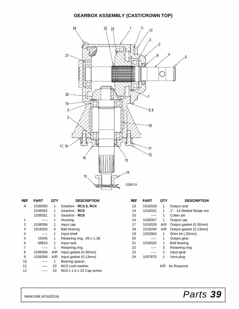
GEARBOX ASSEMBLY (CAST/CROWN TOP)
REF PART QTY DESCRIPTION
A 1038350 1 Gearbox - RC3.5, RC41038352 1 Gearbox - RC51038351 1 Gearbox - RC6
1 ----- 1 Housing2 1038356 1 Input cap3 1018326 3 Ball bearing4 ----- 1 Input shaft5 15345 1 Retaining ring, .05 x 1.386 58815 1 Input seal7 ----- 1 Retaining ring8 1038358 A/R Input gasket (0.30mm)9 1038359 A/R Input gasket (0.13mm)
10 ----- 1 Bearing spacer11 ----- 10 M10 Lock washer12 ----- 10 M10 x 1.5 x 25 Cap screw
REF PART QTY DESCRIPTION
13 1018328 1 Output seal14 1018331 1 1" - 14 Slotted flange nut15 ----- 1 Cotter pin16 1038357 1 Output cap17 1018329 A/R Output gasket (0.30mm)18 1018330 A/R Output gasket (0.13mm)19 1032963 1 Shim kit (.20mm)20 ----- 1 Output gear21 1018325 1 Ball bearing22 ----- 3 Retaining ring23 ----- 1 Input gear24 1037875 1 Vent plug
A/R As Required
40 Parts MAN1048 (4/16/2014)
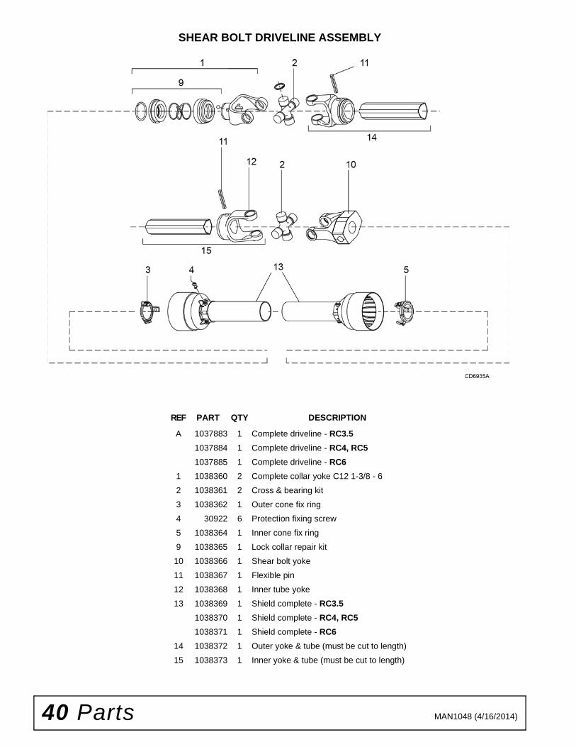
SHEAR BOLT DRIVELINE ASSEMBLY
REF PART QTY DESCRIPTION
A 1037883 1 Complete driveline - RC3.5
1037884 1 Complete driveline - RC4, RC5
1037885 1 Complete driveline - RC6
1 1038360 2 Complete collar yoke C12 1-3/8 - 6
2 1038361 2 Cross & bearing kit
3 1038362 1 Outer cone fix ring
4 30922 6 Protection fixing screw
5 1038364 1 Inner cone fix ring
9 1038365 1 Lock collar repair kit
10 1038366 1 Shear bolt yoke
11 1038367 1 Flexible pin
12 1038368 1 Inner tube yoke
13 1038369 1 Shield complete - RC3.5
1038370 1 Shield complete - RC4, RC5
1038371 1 Shield complete - RC6
14 1038372 1 Outer yoke & tube (must be cut to length)
15 1038373 1 Inner yoke & tube (must be cut to length)

Parts 41MAN1048 (4/16/2014)
SLIP CLUTCH DRIVELINE ASSEMBLY
REF PART QTY DESCRIPTION
A 1038322 1 Complete drive - RC3.5
1038323 1 Complete drive - RC4, RC5
1038324 1 Complete drive - RC6
1 1038360 2 Complete collar yoke C12 1-3/8 - 6
2 1038361 2 Cross & bearing kit
3 1038362 1 Outer cone fix ring
4 30922 6 Protection fixing ring
5 1038364 1 Inner come fix ring
9 1038365 1 Lock collar repair kit
10 1038375 1 Complete slip clutch
11 1038376 8 Spring
12 1038377 1 Flanged yoke
13 1038378 1 Bushing
14 1038379 2 Friction disk
15 1038380 1 Special hub F10
16 1038381 1 Pressure plate
17 1038382 1 End plate
18 1028786 8 Bolt & nut M10 x 85
19 1038367 2 Flexible pin
20 1038383 1 Outer yoke tube
21 1038368 1 Inner tube yoke
22 1038384 1 Shield complete - RC3.5
1038385 1 Shield complete - RC4, RC5
1038386 1 Shield complete - RC6
23 1038372 1 Outer yoke & tube (must be cut to length)
24 1038373 1 Inner yoke & tube (must be cut to length)
25 1024632 1 1/2 NC x 3 Hex Head Cap Screw, GR8
26 765 1 1/2 NC Hex lock nut

42 Parts MAN1048 (4/16/2014)
FRONT AND REAR CHAIN SHIELDING (OPTIONAL)
REPLACEABLE SKID SHOES (OPTIONAL)
REF QTYPARTRC3.5
PARTRC4
PARTRC5
PARTRC6
DESCRIPTION
1 1 1037930 1037934 1037938 1037942 Right front chain plate
2 1 1037931 1037935 1037939 1037943 Left front chain plate
3 1 1037932 1037936 1037940 1037944 Right rear chain plate
4 1 1037933 1037937 1037941 1037945 Left rear chain plate
5 AR 4765 4765 4765 4765 1/4 - 4 Link chain
6 AR 4763 4763 4763 4763 1/4 - 3 Link chain
7 2 1003643 1003643 1003644 1003646 .243 Dia. Bent pin
8 2 1003638 1003639 1003642 57249 .234 Dia. Bent pin
9 6697* 6697* 6697* 6697* 3/8 NC x 1 Carriage bolt GR5
10 14350* 14350* 14350* 14350* 3/8 NC Flange lock nut
AR As Required
* Standard hardware, obtain locally
REF PART QTY DESCRIPTION
A 1038335 1 Kit, bolt-on skid shoes
1 1038336 2 Skid shoe
2 21636 6 Bolt, 3/8 x 1-1/4 clipped head plow
3 14350 * 6 3/8 NC Flange lock nut
* Standard hardware, obtain locally

Bolt Torque & Size Charts (Rev. 3/28/2007)43 Appendix
BOLT TORQUE CHARTAlways tighten hardware to these values unless a different torque value or tightening procedure is listed for a specific application.
Fasteners must always be replaced with the same grade as specified in the manual parts list.
Always use the proper tool for tightening hardware: SAE for SAE hardware and Metric for metric hardware.
Make sure fastener threads are clean and you start thread engagement properly.
All torque values are given to specifications used on hardware defined by SAE J1701 MAR 99 & J1701M JUL 96.
Diameter (Inches)
WrenchSize
MARKING ON HEAD
SAE 2 SAE 5 SAE 8
lbs-ft N-m lbs-ft N-m lbs-ft N-m
1/4" 7/16" 6 8 10 13 14 18
5/16" 1/2" 12 17 19 26 27 37
3/8" 9/16" 23 31 35 47 49 67
7/16" 5/8" 36 48 55 75 78 106
1/2" 3/4" 55 75 85 115 120 163
9/16" 13/16" 78 106 121 164 171 232
5/8" 15/16" 110 149 170 230 240 325
3/4" 1-1/8" 192 261 297 403 420 569
7/8" 1-5/16" 306 416 474 642 669 907
1" 1-1/2" 467 634 722 979 1020 1383
Diameter & Thread Pitch (Millimeters)
Wrench Size
Coarse Thread Fine Thread
Diameter & Thread Pitch (Millimeters)
Marking on Head Marking on Head
Metric 8.8 Metric 10.9 Metric 8.8 Metric 10.9
N-m lbs-ft N-m lbs-ft N-m lbs-ft N-m lbs-ft
6 x 1.0 10 mm 8 6 11 8 8 6 11 8 6 x 1.0
8 x 1.25 13 mm 20 15 27 20 21 16 29 22 8 x 1.0
10 x 1.5 16 mm 39 29 54 40 41 30 57 42 10 x 1.25
12 x 1.75 18 mm 68 50 94 70 75 55 103 76 12 x 1.25
14 x 2.0 21 mm 109 80 151 111 118 87 163 120 14 x 1.5
16 x 2.0 24 mm 169 125 234 173 181 133 250 184 16 x 1.5
18 x 2.5 27 mm 234 172 323 239 263 194 363 268 18 x 1.5
20 x 2.5 30 mm 330 244 457 337 367 270 507 374 20 x 1.5
22 x 2.5 34 mm 451 332 623 460 495 365 684 505 22 x 1.5
24 x 3.0 36 mm 571 421 790 583 623 459 861 635 24 x 2.0
30 x 3.0 46 mm 1175 867 1626 1199 1258 928 1740 1283 30 x 2.0
A
SAE SERIES TORQUE CHART
SAE Bolt Head Identification
SAE Grade 2(No Dashes)
SAE Grade 5(3 Radial Dashes)
SAE Grade 8(6 Radial Dashes)
A
METRIC SERIES TORQUE CHART
Metric Bolt Head Identification
8.8
MetricGrade 10.9
10.9
MetricGrade 8.8
A
A A
Typical Washer Installations Lock Washer
Flat Washer
8/9/00
Bolt

Appendix 44Bolt Torque & Size Charts (Rev. 3/28/2007)
BOLT SIZE CHARTNOTE: Chart shows bolt thread sizes and corresponding head (wrench) sizes for standard SAE and metric bolts.
ABBREVIATIONSAG .............................................................. Agriculture
ASABE ....................American Society of Agricultural & Biological Engineers (formerly ASAE)
ASAE....... American Society of Agricultural Engineers
ATF............................... Automatic Transmission Fluid
BSPP.............................British Standard Pipe Parallel
BSPTM ................British Standard Pipe Tapered Male
CV ....................................................Constant Velocity
CCW.............................................. Counter-Clockwise
CW .............................................................. Clockwise
F .......................................................................Female
FT .............................................................. Full Thread
GA .....................................................................Gauge
GR (5, etc.) ........................................... Grade (5, etc.)
HHCS ........................................Hex Head Cap Screw
HT........................................................... Heat-Treated
JIC ............................. Joint Industry Council 37° Flare
LH.................................................................Left Hand
LT ...........................................................................Left
m ........................................................................ Meter
mm ............................................................... Millimeter
M ..........................................................................Male
MPa......................................................... Mega Pascal
N ......................................................................Newton
NC...................................................... National Coarse
NF ...........................................................National Fine
NPSM.....................National Pipe Straight Mechanical
NPT.......................................... National Pipe Tapered
NPT SWF.........National Pipe Tapered Swivel Female
ORBM ...........................................O-Ring Boss - Male
P........................................................................... Pitch
PBY...................................................... Power-Beyond
psi ......................................... Pounds per Square Inch
PTO.....................................................Power Take Off
QD.................................................... Quick Disconnect
RH.............................................................. Right Hand
ROPS........................... Roll-Over Protective Structure
RPM ........................................Revolutions Per Minute
RT ........................................................................Right
SAE..........................Society of Automotive Engineers
UNC ..................................................... Unified Coarse
UNF...........................................................Unified Fine
UNS ..................................................... Unified Special
5/16 3/8 1/2 5/8 3/4 7/8SAE Bolt Thread Sizes
MM 25 50 75 100 125 150 175
IN 1 7
Metric Bolt Thread Sizes8MM 18MM14MM12MM10MM 16MM
2 3 4 5 6

Index 45MAN1048 (4/16/2014)
INDEX
ASSEMBLY
Dealer Set-Up Instructions 30
DEALER CHECK LISTS
Delivery (Dealer’s Responsibility) 28Pre-Delivery (Dealer’s Responsibility) 28
DEALER SERVICE
Crossbar
Installation 26Removal 25
Gearbox Maintenance 22Horizontal Leak Repair 23Seal Installation 22Seal Replacement 22Vertical Shaft Repair 23
Gearbox Repair
Disassemble Gearbox 25, 29Reassemble Gearbox 26, 29, 30Reinstall Gearbox 26Remove Gearbox 25, 29
Universal Joint
Assembly 27Disassembly 26Repair 26
GENERAL
Abbreviations 44Bolt Size Chart 44Bolt Torque Chart 43General Information 4Introduction 2Obtaining Replacement Manuals 2Product Registration 2Specifications 4Table of Contents 3Warranty
Product 46Replacement Parts 47
OPERATION
Adjustments
Attitude 15Check Chains 16Cutting Height 15Shredding 15
Attaching Cutter to Tractor
Attachment 12Quick Hitch 13
Driveline
Attachment 13Interference Check 15PTO Installation & Removal 13Shortening 14
Mowing Speed 12Operating Technique 16Pre-Operation Check List (Owner’s Responsibility)
16Storage 16Tractor Stability 12
OWNER SERVICE
Blade
Installation 18Removal 18Servicing 18Sharpening 19
Blocking Method 17Cleaning
After Each Use 20Periodically or Before Extended Storage 20
Driveline Shear Bolt Replacement 20Lubrication Information 17
Driveline 17Gearbox 17Lubrication Chart 18
Shielding Repair 20Slip Clutch Adjustment 19Troubleshooting 21
PARTS
Index to Parts Lists 35
SAFETY
Check Lists
Delivery (Dealer’s Responsibility) 28Pre-Delivery (Dealer’s Responsibility) 28Pre-Operation (Owner’s Responsibility) 16
Online Safety Video 5, 6Safety & Instructional Decals 10, 11Safety Rules 7, 8, 9Safety Symbols Explained 2

F-8494 (Rev. 1/3/2017)
©2017 Woods Equipment Company. All rights reserved. Woods® and the Woods logo are trademarks of Woods Equipment Company. All othertrademarks, trade names, or service marks not owned by Woods Equipment Company that appear in this manual are the property of their respectivecompanies or mark holders. Specifications subject to change without notice.
WOODS®| A Blount International Brand2606 South Illinois Route 2 Post Office Box 1000Oregon, Illinois 61061 USA
800-319-6637 tel800-399-6637 faxwoodsequipment.com
WARRANTY(Replacement Parts For All Models Except Mow’n MachineTM
Zero-Turn Mowers and Woods BoundaryTM Utility Vehicles)
Woods Equipment Company (“WOODS”) warrants this product to be free from defect in material andworkmanship for a period of ninety (90) days from the date of delivery of the product to the original purchaserwith the exception of V-belts, which will be free of defect in material and workmanship for a period of 12 months.
Under no circumstances will this Warranty apply in the event that the product, in the good faith opinion ofWOODS, has been subjected to improper operation, improper maintenance, misuse, or an accident. This Warrantydoes not cover normal wear or tear, or normal maintenance items.
This Warranty is extended solely to the original purchaser of the product. Should the original purchaser sell orotherwise transfer this product to a third party, this Warranty does not transfer to the third party purchaser in anyway. There are no third party beneficiaries of this Warranty.
WOODS’ obligation under this Warranty is limited to, at WOODS’ option, the repair or replacement, free ofcharge, of the product if WOODS, in its sole discretion, deems it to be defective or in noncompliance with thisWarranty. The product must be returned to WOODS with proof of purchase within thirty (30) days aftersuch defect or noncompliance is discovered or should have been discovered, routed through the dealer anddistributor from whom the purchase was made, transportation charges prepaid. WOODS shall completesuch repair or replacement within a reasonable time after WOODS receives the product. THERE ARE NOOTHER REMEDIES UNDER THIS WARRANTY. THE REMEDY OF REPAIR OR REPLACEMENT IS THESOLE AND EXCLUSIVE REMEDY UNDER THIS WARRANTY.
THERE ARE NO WARRANTIES WHICH EXTEND BEYOND THE DESCRIPTION ON THE FACE OF THISWARRANTY. WOODS MAKES NO OTHER WARRANTY, EXPRESS OR IMPLIED, AND WOODSSPECIFICALLY DISCLAIMS ANY IMPLIED WARRANTY OF MERCHANTABILITY AND/OR ANYIMPLIED WARRANTY OF FITNESS FOR A PARTICULAR PURPOSE.
WOODS shall not be liable for any incidental or consequential losses, damages or expenses, arising directlyor indirectly from the product, whether such claim is based upon breach of contract, breach of warranty,negligence, strict liability in tort or any other legal theory. Without limiting the generality of the foregoing,Woods specifically disclaims any damages relating to (i) lost profits, business, revenues or goodwill; (ii) loss ofcrops; (iii) loss because of delay in harvesting; (iv) any expense or loss incurred for labor, supplies, substitutemachinery or rental; or (v) any other type of damage to property or economic loss.
This Warranty is subject to any existing conditions of supply which may directly affect WOODS’ ability to obtainmaterials or manufacture replacement parts.
No agent, representative, dealer, distributor, service person, salesperson, or employee of any company, includingwithout limitation, WOODS, its authorized dealers, distributors, and service centers, is authorized to alter, modify,or enlarge this Warranty.
Answers to any questions regarding warranty service and locations may be obtained by contacting:
F-3079 (Rev. 7/31/2017)
WOODS®| A Blount International Brand2606 South Illinois Route 2 Post Office Box 1000Oregon, Illinois 61061 USA
800-319-6637 tel800-399-6637 faxwoodsequipment.com
WARRANTYAll Models Except Mow’n MachineTM Zero-Turn Mowers
Please Enter Information Below and Save for Future Reference.
Date Purchased: ____________________________ From (Dealer): __________________________________________
Model Number: ____________________________ Serial Number: __________________________________________
Woods Equipment Company (“WOODS”) warrants this product to be free from defect in material and workmanship. Except as otherwise set forthbelow, the duration of this Warranty shall be for TWELVE (12) MONTHS COMMENCING ON THE DATE OF DELIVERY OF THEPRODUCT TO THE ORIGINAL PURCHASER.
All current model backhoes, loaders and mounts (except 3-pt. SAF-T-LOK mounts) are warranted for two (2) years from the date of delivery tothe original purchaser. The limited warranty covers any defects in the material and/or workmanship. Following the proper, recommendedinstallation by an authorized Woods Dealer and normal use of a Woods mounting and backhoe or loader, if a tractor incurs damage resulting fromthe attachment, Woods will cover the existing tractor warranty in the event the manufacturer voids its tractor warranty because of the attachment.Warranty does not cover any misuse or abusive conditions that could cause premature wear or damage to attachment or tractor.
The warranty periods for specific parts or conditions are listed below:
Under no circumstances will this Warranty apply in the event that the product, in the good faith opinion of WOODS, has been subjected toimproper operation, improper maintenance, misuse, or an accident. This Warranty does not apply in the event that the product has been materiallymodified or repaired by someone other than WOODS, a WOODS authorized dealer or distributor, and/or a WOODS authorized service center.This Warranty does not cover normal wear or tear, or normal maintenance items. This Warranty also does not cover repairs made with parts otherthan those obtainable through WOODS.
This Warranty is extended solely to the original purchaser of the product. Should the original purchaser sell or otherwise transfer this product to athird party, this Warranty does not transfer to the third party purchaser in any way. There are no third party beneficiaries of this Warranty.
WOODS makes no warranty, express or implied, with respect to engines, batteries, tires or other parts or accessories not manufactured byWOODS. Warranties for these items, if any, are provided separately by their respective manufacturers.
WOODS’ obligation under this Warranty is limited to, at WOODS’ option, the repair or replacement, free of charge, of the product if WOODS, inits sole discretion, deems it to be defective or in noncompliance with this Warranty. The product must be returned to WOODS with proof ofpurchase within thirty (30) days after such defect or noncompliance is discovered or should have been discovered, routed through thedealer and distributor from whom the purchase was made, transportation charges prepaid. WOODS shall complete such repair orreplacement within a reasonable time after WOODS receives the product. THERE ARE NO OTHER REMEDIES UNDER THIS WARRANTY.THE REMEDY OF REPAIR OR REPLACEMENT IS THE SOLE AND EXCLUSIVE REMEDY UNDER THIS WARRANTY.
THERE ARE NO WARRANTIES WHICH EXTEND BEYOND THE DESCRIPTION ON THE FACE OF THIS WARRANTY. WOODSMAKES NO OTHER WARRANTY, EXPRESS OR IMPLIED, AND WOODS SPECIFICALLY DISCLAIMS ANY IMPLIED WARRANTYOF MERCHANTABILITY AND/OR ANY IMPLIED WARRANTY OF FITNESS FOR A PARTICULAR PURPOSE.
WOODS shall not be liable for any incidental or consequential losses, damages or expenses, arising directly or indirectly from theproduct, whether such claim is based upon breach of contract, breach of warranty, negligence, strict liability in tort or any other legaltheory. Without limiting the generality of the foregoing, Woods specifically disclaims any damages relating to (i) lost profits, business, revenuesor goodwill; (ii) loss of crops; (iii) loss because of delay in harvesting; (iv) any expense or loss incurred for labor, supplies, substitute machinery orrental; or (v) any other type of damage to property or economic loss.
This Warranty is subject to any existing conditions of supply which may directly affect WOODS’ ability to obtain materials or manufacturereplacement parts.
No agent, representative, dealer, distributor, serviceperson, salesperson, or employee of
Part or Condition
WarrantedModel Number
Duration (from date of delivery to the original
purchaser)
All units invoiced after 4/30/2012
Gearbox components
BB48X, BB60X, BB72X, BB84X, BB600X, BB720X, BB840X, BB6000X, BB7200X, BB8400X,DS12.50, TS14.60, DS1440, TS1680, DS8.30, DS10.40, DS8.50, DSO8.50, DS10.50, DSO10.50,DBH5.30, DBH6.30
6 years
BW12, BW15, BW126X, BW180X, BW126XHD, BW180XHD, BW1260X, BW1800XBW10.50, BW10.50Q, BW15.50, BW15.50Q, BW10.60, BW10.60Q, BW15.60, BW15.60Q,BW10.70, BW10.70Q, BW15.70, BW15.70Q
BW240X, BW240XHD, BW1620X, BW2400X
RD990X, PRD6000, PRD7200, PRD8400, S15CD, S20CD, S22CD, S25CD, S27CD, S30CD, TC/R74, TC/R68, TC/R60, TBW144, TBW180, TBW204, TSG50, S12ED, S15ED, S18ED, S20ED,TPD25, TPD35, TPD65, TPD95
RDC54, RD60, RD72, TBW150C, TS/R60, TS/R52, TS/R44, RC3.5, RC4, RC5, RC6 3 years (1 year if used in rental or commercial applications)
Blade spindles RD990X, PRD6000, PRD7200, PRD8400, TBW144, TBW180, TBW204 3 years

PART NO.
MAN1048
© 2018 Woods Equipment Company. All rights reserved. Woods® and the Woods logo are trademarks of Woods Equipment Company. All othertrademarks, trade names, or service marks not owned by Woods Equipment Company that appear in this manual are the property of their respec-tive companies or mark holders. Specifications subject to change without notice.
Woods Equipment
A Blount International Company
2606 South Illinois Route 2Post Office Box 1000Oregon, Illinois 61061
800-319-6637 tel800-399-6637 faxwoodsequipment.com