Rosemount Engineered · PDF fileProduct Data Sheet 00813-0100-4650, Rev DA Catalog 2008 - 2009...
32
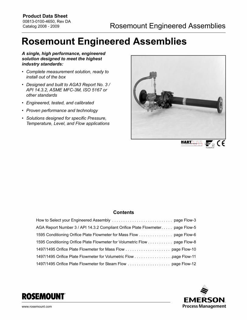
Product Data Sheet 00813-0100-4650, Rev DA Catalog 2008 - 2009 Rosemount Engineered Assemblies www.rosemount.com A single, high performance, engineered solution designed to meet the highest industry standards: • Complete measurement solution, ready to install out of the box • Designed and built to AGA3 Report No. 3 / API 14.3.2, ASME MFC-3M, ISO 5167 or other standards • Engineered, tested, and calibrated • Proven performance and technology • Solutions designed for specific Pressure, Temperature, Level, and Flow applications Contents How to Select your Engineered Assembly . . . . . . . . . . . . . . . . . . . . . . . . . . . page Flow-3 AGA Report Number 3 / API 14.3.2 Compliant Orifice Plate Flowmeter . . . . . page Flow-5 1595 Conditioning Orifice Plate Flowmeter for Mass Flow . . . . . . . . . . . . . . . page Flow-6 1595 Conditioning Orifice Plate Flowmeter for Volumetric Flow . . . . . . . . . . . page Flow-8 1497/1495 Orifice Plate Flowmeter for Mass Flow . . . . . . . . . . . . . . . . . . . . page Flow-10 1497/1495 Orifice Plate Flowmeter for Volumetric Flow . . . . . . . . . . . . . . . . . page Flow-11 1497/1495 Orifice Plate Flowmeter for Steam Flow . . . . . . . . . . . . . . . . . . . page Flow-12 Rosemount Engineered Assemblies
Transcript of Rosemount Engineered · PDF fileProduct Data Sheet 00813-0100-4650, Rev DA Catalog 2008 - 2009...
Product Data Sheet00813-0100-4650, Rev DA
Catalog 2008 - 2009 Rosemount Engineered Assemblies
Rosemount Engineered Assemblies
A single, high performance, engineeredsolution designed to meet the highest
industry standards:
• Complete measurement solution, ready to
install out of the box
• Designed and built to AGA3 Report No. 3 /
API 14.3.2, ASME MFC-3M, ISO 5167 or
other standards
• Engineered, tested, and calibrated
• Proven performance and technology
• Solutions designed for specific Pressure,
Temperature, Level, and Flow applications
www.ro
Contents
How to Select your Engineered Assembly . . . . . . . . . . . . . . . . . . . . . . . . . . . page Flow-3
AGA Report Number 3 / API 14.3.2 Compliant Orifice Plate Flowmeter. . . . . page Flow-5
1595 Conditioning Orifice Plate Flowmeter for Mass Flow . . . . . . . . . . . . . . . page Flow-6
1595 Conditioning Orifice Plate Flowmeter for Volumetric Flow . . . . . . . . . . . page Flow-8
1497/1495 Orifice Plate Flowmeter for Mass Flow . . . . . . . . . . . . . . . . . . . . page Flow-10
1497/1495 Orifice Plate Flowmeter for Volumetric Flow . . . . . . . . . . . . . . . . .page Flow-11
1497/1495 Orifice Plate Flowmeter for Steam Flow . . . . . . . . . . . . . . . . . . . page Flow-12
semount.com
Product Data Sheet00813-0100-4650, Rev DA
Catalog 2008 - 2009Rosemount Engineered Assemblies
One Application, One Purchase Order, One Assembly...
Infinite Possibilities.
Rosemount Engineered Assemblies maintains the Emerson Process Management tradition of excellence by
providing high quality solutions for all your measurement needs. Engineered to combine best products and
best installation practices, Rosemount Engineered Assemblies provide a single, high performance,
engineered solution designed to meet the highest industry standards.
Complete measurement solution, ready to install out of the box
The engineered assembly is factory configured,
calibrated, leak tested, and ready to install right out of
the box.
Designed and built to AGA3 Report No. 3 / API 14.3.2, ASME MFC-3M, ISO 5167 or other standards
Engineered Assemblies are engineered and built to the
highest standards. Flowmeters are engineered to 40
CFR 75 Appendix D and E standards ensuring high
accuracy and agency compliance (AGA3 Report No. 3
/ API 14.3.2, EPA, etc.). Engineered Assemblies are
ideal for EPA Acid Rain compliance or Custody
Transfer applications.
Engineered, tested, and calibrated
Engineered Assemblies are engineered into a single
assembly. One installation means reduced process
penetrations, potential leak points, and lower
installation costs saving start up time and money.
AGA3 Report No. 3 / API 14.3.2 Compliant Orifice
Plate Flowmeter:
The highest accuracy orifice plate meter run when
measuring gases and liquids.
1595 Conditioning Orifice Plate Flowmeter for
Mass Flow:
High accuracy with the shortest piping requirements for
gas and steam.
1595 Conditioning Orifice Plate Flowmeter for
Volumetric Flow:
High accuracy with the shortest piping requirements for
liquids.
Proven performance and technology
The entire Rosemount transmitter family is available
with Engineered Assemblies, bringing the
communication benefits of Hart and Fieldbus,
transmitter stability of up to 10 years, and flow
accuracy better than ±1.0%.
Solutions designed for specific Pressure, Temperature, Level and Flow applications
Emerson Process Management will work directly with
you to meet the needs of your measurement solutions.
For additional Engineered Assembly possibilities or
capabilities please contact your local Emerson Process
Management representative to design a specific
application solution.
ADVANCED PLANTWEB FUNCTIONALITY
Engineered Assemblies Powers PlantWeb
by combining the best installation
practices with the best transmitters and
field intelligence to reduce project risk and
cost, and improve plant availability.
1497/1495 Orifice Plate Flowmeter for Mass Flow:
Repeatability when measuring gases.
1497/1495 Orifice Plate Flowmeter for Volumetric
Flow:
Repeatability when measuring liquids.
1497/1495 Orifice Plate Flowmeter for Steam Flow:
Repeatability when measuring steam.
Flow-2
Product Data Sheet00813-0100-4650, Rev DA
Catalog 2008 - 2009
Flow-3
Rosemount Engineered Assemblies
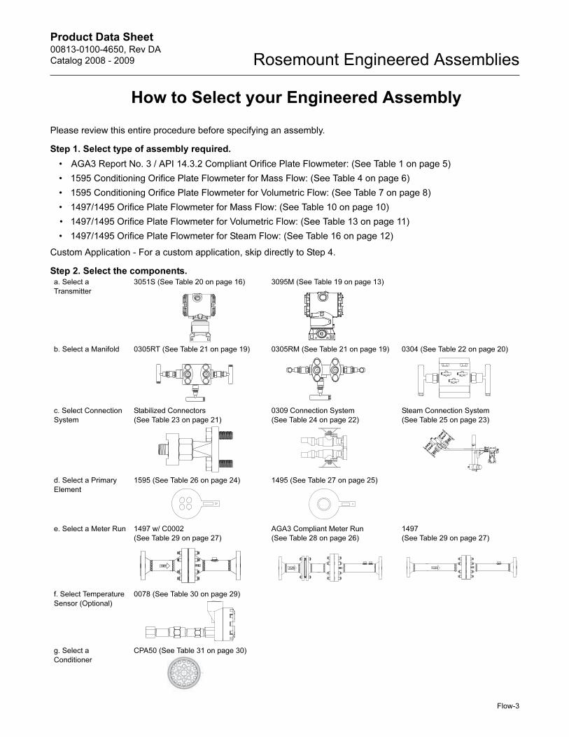
How to Select your Engineered Assembly
Please review this entire procedure before specifying an assembly.
Step 1. Select type of assembly required.
• AGA3 Report No. 3 / API 14.3.2 Compliant Orifice Plate Flowmeter: (See Table 1 on page 5)
• 1595 Conditioning Orifice Plate Flowmeter for Mass Flow: (See Table 4 on page 6)
• 1595 Conditioning Orifice Plate Flowmeter for Volumetric Flow: (See Table 7 on page 8)
• 1497/1495 Orifice Plate Flowmeter for Mass Flow: (See Table 10 on page 10)
• 1497/1495 Orifice Plate Flowmeter for Volumetric Flow: (See Table 13 on page 11)
• 1497/1495 Orifice Plate Flowmeter for Steam Flow: (See Table 16 on page 12)
Custom Application - For a custom application, skip directly to Step 4.
Step 2. Select the components.a. Select a
Transmitter
3051S (See Table 20 on page 16) 3095M (See Table 19 on page 13)
b. Select a Manifold 0305RT (See Table 21 on page 19) 0305RM (See Table 21 on page 19) 0304 (See Table 22 on page 20)
c. Select Connection
System
Stabilized Connectors
(See Table 23 on page 21)
0309 Connection System
(See Table 24 on page 22)
Steam Connection System
(See Table 25 on page 23)
d. Select a Primary
Element
1595 (See Table 26 on page 24) 1495 (See Table 27 on page 25)
e. Select a Meter Run 1497 w/ C0002
(See Table 29 on page 27)
AGA3 Compliant Meter Run
(See Table 28 on page 26)
1497
(See Table 29 on page 27)
f. Select Temperature
Sensor (Optional)
0078 (See Table 30 on page 29)
g. Select a
Conditioner
CPA50 (See Table 31 on page 30)

Product Data Sheet00813-0100-4650, Rev DA
Catalog 2008 - 2009Rosemount Engineered Assemblies
Flow-4
Step 3. Put all the model numbers together and complete the Configuration Data Sheet
(See Document number 00806-0100-4650).
Step 4. Contact your local Emerson Process Management Representative.
CONFIGURATION NOTES
It is possible to specify components from this PDS in an assembly that will not work together. Please contact your
local Emerson Process Management representative to receive a full quote on any assembly. Below are two sample
assemblies with correct model numbers.
The following Engineered Assembly example is an 8” AGA Report Number 3/API 14.3.2 Compliant Orifice Plate
Flowmeter using explosion-proof components:
The following Engineered Assembly example is of a 3” 1497/1495 Orifice Plate Flowmeter for Volumetric Flow with
a remote LCD display:
Quantity Model Number
1 CPS / Assembly Part Number from Table 3 - CPSDPFL-00610-00
1 Mass flow transmitter from Table 19 - 3095MA23A0011AA00NABN500C2Q4Q8
1 Manifold from Table 19 - Included with transmitter (N500)
1 Connectors from Table 23 - 116680820003
1 Orifice Plate from Table 27 - 1495PC080A3SBxxxxxBC
1 Meter Run from Table 28 - AGA3C080A3F
1 RTD from Table 30 - 0078P21C30A040T24E5X8Q4XA
1 Flow Conditioner from Table 31 - CPA50E.080
Quantity Model Number
1 CPS / Assembly Part Number from Table 15 - CPSDPFL-00555-00
1 Volumetric flow transmitter from Table 20 - 3051S1CD2A2A11A2EC1M8Q4
1 Manifold from Table 21 - 0305RT32A11
1 Connectors from Table 23 - 116680830001
1 Orifice Plate from Table 27 - 1495PC030A3SAxxxxxBC
1 Meter Section from Table 29 - 1497WN030A3CFF
1 RTD - not required
Product Data Sheet00813-0100-4650, Rev DA
Catalog 2008 - 2009 Rosemount Engineered Assemblies
Flow-5
AGA Report Number 3 / API 14.3.2
Compliant Orifice Plate Flowmeter
FIGURE 1. AGA3 Report Number 3 / API 14.3.2 Compliant Orifice Plate Meter Run
TABLE 1. AGA Report Number 3 / API 14.3.2
Compliant Orifice Plate Flowmeter
DescriptionOrdering
Information Line Size A inch (mm) B inch (mm) C inch (mm)
1 CPS / Assembly Part Number Table 3 2 10.1 (258) 16.1 (411) 20.3 (513)
2 3095 Flow transmitter Table 19 3 15.2 (387) 24.2 (615) 24.3 (615)
3 Manifold Table 21 4 20.2 (513) 32.2 (819) 32.3 (819)
4 Stabilized connectors Table 23 6 30.2 (768) 48.2 (1224) 42.3 (1074)
5 1495 Orifice Plate Table 27 8 40.2 (1020) 64.2 (1629) 52.4 (1329)
6 AGA3 Compliant Orifice Plate Meter Runs Table 28 10 50.2 (1275) 80.2 (2037) 65.4 (1662)
7 0078 RTD and thermowell Table 30 12 60.2 (1530) 96.2 (2442) 78.4 (1992)
8 Flow Conditioner Table 31(1) Tolerances for all dimensions within ±0.1 in (2.54 mm).
(2) For pipe sizes of 2-6 in., D equals 3/8-in. for standard gaskets and 1/2-in. for spiral wound gaskets. E equals 1/4-in. for standard gaskets and 3/8-in. for spiral wound gaskets. For pipe sizes 8-12 in., E equals 3/8-in. for standard gaskets and 1/2-in. for spiral wound gaskets.
TABLE 3. AGA Report Number 3 / API 14.3.2 Compliant Orifice Plate Meter Run Ordering Information(1)
(1) Higher Flange Ratings available.
Orifice Flange Union
Line Size ANSI Class 300 ANSI Class 600 ANSI Class 900
2 inch CPSDPFL-00605-00 CPSDPFL-00605-01 CPSDPFL-00605-02
3 inch CPSDPFL-00607-00 CPSDPFL-00607-01 CPSDPFL-00607-02
4 inch CPSDPFL-00608-00 CPSDPFL-00608-01 CPSDPFL-00608-02
6 inch CPSDPFL-00609-00 CPSDPFL-00609-01 CPSDPFL-00609-02
8 inch CPSDPFL-00610-00 CPSDPFL-00610-01 CPSDPFL-00610-02
10 inch CPSDPFL-00611-00 CPSDPFL-00611-01 CPSDPFL-00611-02
12 inch CPSDPFL-00611-07 CPSDPFL-00611-08 CPSDPFL-00611-09
2
3
75
4
6
CBA
8
Beveled
Temp. Sensor Cable Connection*
(*) See 3095 Ordering Information - Process Temperature Input for specification.
D E
TABLE 2. Meter Run Lay-Lengths(1)(2)
Product Data Sheet00813-0100-4650, Rev DA
Catalog 2008 - 2009Rosemount Engineered Assemblies
1595 Conditioning Orifice Plate Flowmeter for Mass Flow
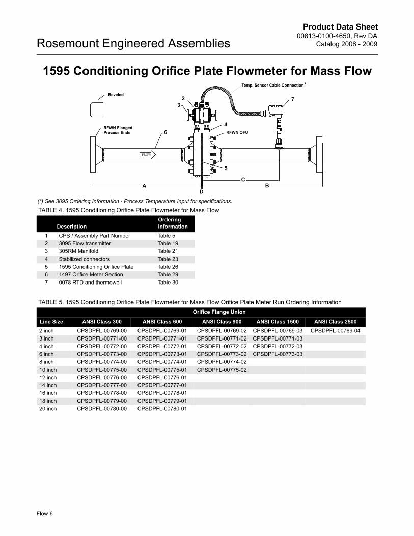
TABLE 4. 1595 Conditioning Orifice Plate Flowmeter for Mass Flow
DescriptionOrdering
Information
1 CPS / Assembly Part Number Table 5
2 3095 Flow transmitter Table 19
3 305RM Manifold Table 21
4 Stabilized connectors Table 23
5 1595 Conditioning Orifice Plate Table 26
6 1497 Orifice Meter Section Table 29
7 0078 RTD and thermowell Table 30
2
37
5
4
6
Beveled
Temp. Sensor Cable Connection*
(*) See 3095 Ordering Information - Process Temperature Input for specifications.
RFWN Flanged
Process Ends
CBA
D
RFWN OFU
5
TABLE 5. 1595 Conditioning Orifice Plate Flowmeter for Mass Flow Orifice Plate Meter Run Ordering Information
Orifice Flange Union
Line Size ANSI Class 300 ANSI Class 600 ANSI Class 900 ANSI Class 1500 ANSI Class 2500
2 inch CPSDPFL-00769-00 CPSDPFL-00769-01 CPSDPFL-00769-02 CPSDPFL-00769-03 CPSDPFL-00769-04
3 inch CPSDPFL-00771-00 CPSDPFL-00771-01 CPSDPFL-00771-02 CPSDPFL-00771-03
4 inch CPSDPFL-00772-00 CPSDPFL-00772-01 CPSDPFL-00772-02 CPSDPFL-00772-03
6 inch CPSDPFL-00773-00 CPSDPFL-00773-01 CPSDPFL-00773-02 CPSDPFL-00773-03
8 inch CPSDPFL-00774-00 CPSDPFL-00774-01 CPSDPFL-00774-02
10 inch CPSDPFL-00775-00 CPSDPFL-00775-01 CPSDPFL-00775-02
12 inch CPSDPFL-00776-00 CPSDPFL-00776-01
14 inch CPSDPFL-00777-00 CPSDPFL-00777-01
16 inch CPSDPFL-00778-00 CPSDPFL-00778-01
18 inch CPSDPFL-00779-00 CPSDPFL-00779-01
20 inch CPSDPFL-00780-00 CPSDPFL-00780-01
Flow-6

Product Data Sheet00813-0100-4650, Rev DA
Catalog 2008 - 2009 Rosemount Engineered Assemblies
TABLE 6. 1595 Conditioning Orifice Plate Flowmeter for Mass Flow Dimensions(1) (2)
METER SECTION LENGTHS
Line Size End Connection OFU A inch(mm) B inch(mm) C inch(mm)
2 150# 300# 5.9 (151) 11.9 (303) 6.3 (160)
300# / Beveled 300# 6.2 (157) 12.1 (308) 6.3 (160)
600# / Beveled 600# 6.6 (167) 12.5 (318) 6.3 (160)
900# / Beveled 900# 8.6 (217) 14.5 (369) 7.2 (183)
1500# / Beveled 1500# 8.6 (217) 14.5 (369) 7.2 (183)
2500# / Beveled 2500# 10.6 (268) 16.5 (420) 8.2 (209)
3 150# 300# 6.3 (160) 12.3 (313) 6.5 (165)
300# / Beveled 300# 6.7 (170) 12.6 (321) 6.5 (165)
600# / Beveled 600# 7.1 (179) 13.0 (331) 6.5 (165)
900# / Beveled 900# 8.6 (217) 14.5 (369) 7.2 (183)
1500# / Beveled 1500# 9.8 (249) 15.7 (400) 8.1 (206)
4 150# 300# 10.0 (254) 14.0 (356) 8.0 (204)
300# / Beveled 300# 10.0 (254) 14.0 (356) 8.0 (204)
600# / Beveled 600# 8.6 (217) 15.3 (389) 8.0 (204)
900# / Beveled 900# 9.6 (243) 15.7 (400) 8.0 (204)
1500# / Beveled 1500# 10.3 (262) 16.3 (415) 8.1 (206)
6 150# 300# 12.0 (305) 20.0 (509) 12.0 (305)
300# / Beveled 300# 12.0 (305) 20.0 (509) 12.0 (305)
600# / Beveled 600# 12.0 (305) 20.0 (509) 12.0 (305)
900# / Beveled 900# 11.6 (294) 20.0 (509) 12.0 (305)
1500# / Beveled 1500# 14.1 (357) 22.0 (560) 12.0 (305)
8 All All 16.0 (406) 25.0 (636) 16.0 (407)
10 All All 20.0 (508) 30.0 (764) 20.0 (509)
12 All All 24.0 (610) 35.0 (891) 24.0 (611)
14 All All 28.0 (711) 43.0 (1095) 28.0 (713)
16 All All 32.0 (813) 48.0 (1222) 32.0 (815)
18 All All 36.0 (914) 53.0 (1349) 36.0 (916)
20 All All 40.0 (1016) 58.0 (1476) 40.0 (1018)
(1) Tolerances for all dimensions within ±0.1 in (2.54 mm)
(2) For pipe size of 2-4 in., D equals 1/4-in. for standard gaskets and 3/8-in. for spiral wound gaskets. For pipe sizes of 6-20 in., D equals 3/8-in. for standard gaskets and 1/2-in. for spiral wound gaskets.
Flow-7
Product Data Sheet00813-0100-4650, Rev DA
Catalog 2008 - 2009Rosemount Engineered Assemblies
Flow-8
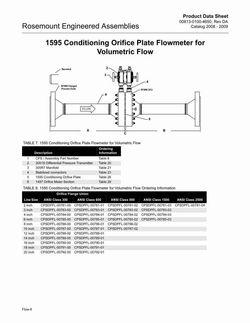
1595 Conditioning Orifice Plate Flowmeter for
Volumetric Flow
TABLE 7. 1595 Conditioning Orifice Plate Flowmeter for Volumetric Flow
DescriptionOrdering
Information
1 CPS / Assembly Part Number Table 8
2 3051S Differential Pressure Transmitter Table 20
3 305RT Manifold Table 21
4 Stabilized connectors Table 23
5 1595 Conditioning Orifice Plate Table 26
6 1497 Orifice Meter Section Table 29
TABLE 8. 1595 Conditioning Orifice Plate Flowmeter for Volumetric Flow Ordering Information
Orifice Flange Union
Line Size ANSI Class 300 ANSI Class 600 ANSI Class 900 ANSI Class 1500 ANSI Class 2500
2 inch CPSDPFL-00781-00 CPSDPFL-00781-01 CPSDPFL-00781-02 CPSDPFL-00781-03 CPSDPFL-00781-04
3 inch CPSDPFL-00783-00 CPSDPFL-00783-01 CPSDPFL-00783-02 CPSDPFL-00783-03
4 inch CPSDPFL-00784-00 CPSDPFL-00784-01 CPSDPFL-00784-02 CPSDPFL-00784-03
6 inch CPSDPFL-00785-00 CPSDPFL-00785-01 CPSDPFL-00785-02 CPSDPFL-00785-03
8 inch CPSDPFL-00786-00 CPSDPFL-00786-01 CPSDPFL-00786-02
10 inch CPSDPFL-00787-00 CPSDPFL-00787-01 CPSDPFL-00787-02
12 inch CPSDPFL-00788-00 CPSDPFL-00788-01
14 inch CPSDPFL-00789-00 CPSDPFL-00789-01
16 inch CPSDPFL-00790-00 CPSDPFL-00790-01
18 inch CPSDPFL-00791-00 CPSDPFL-00791-01
20 inch CPSDPFL-00792-00 CPSDPFL-00792-01
Beveled 2
3
4
6
5
RFWN Flanged
Process Ends
A B
RFWN OFU
C

Product Data Sheet00813-0100-4650, Rev DA
Catalog 2008 - 2009 Rosemount Engineered Assemblies
TABLE 9. 1595 Conditioning Orifice Plate Flowmeter for Volumetric Flow Dimensions(1) (2)
METER SECTION LENGTHS
Line Size End Connection OFUA and B
inch(mm)
2 150# 300# 6.0 (155)
300# / Beveled 300# 6.2 (159)
600# / Beveled 600# 6.6 (167)
900# / Beveled 900# 8.5 (215)
1500# / Beveled 1500# 8.5 (215)
2500# / Beveled 2500# 10.5 (266)
3 150# 300# 6.3 (160)
300# / Beveled 300# 6.6 (168)
600# / Beveled 600# 7.0 (178)
900# / Beveled 900# 8.5 (215)
1500# / Beveled 1500# 9.8 (249)
4 150# 300# 10.0 (254)
300# / Beveled 300# 10.0 (254)
600# / Beveled 600# 8.5 (215)
900# / Beveled 900# 9.5 (241)
1500# / Beveled 1500# 10.3 (262)
6 150# 300# 12.0 (305)
300# / Beveled 300# 12.0 (305)
600# / Beveled 600# 12.0 (305)
900# / Beveled 900# 11.5 (292)
1500# / Beveled 1500# 14.0 (355)
8 All All 16.0 (406)
10 All All 20.0 (508)
12 All All 24.0 (610)
14 All All 28.0 (711)
16 All All 32.0 (813)
18 All All 36.0 (914)
20 All All 40.0 (1016)
(1) Tolerances for all dimensions within ±0.1 in (2.54 mm)
(2) For pipe size of 2-4 in., C equals 1/4-in. for standard gaskets and 3/8-in. for spiral wound gaskets. For pipe sizes of 6-20 in., C equals 3/8-in. for standard gaskets and 1/2-in. for spiral wound gaskets.
Flow-9
Product Data Sheet00813-0100-4650, Rev DA
Catalog 2008 - 2009Rosemount Engineered Assemblies
Flow-10
1497/1495 Orifice Plate Flowmeter for Mass Flow
FIGURE 2. 1497/1495 Orifice Plate Flowmeter for Mass Flow
5
4
AC
B
7
RFWN Flanged Process Ends
3
6
Beveled
(*) See 3095 Ordering Information - Process Temperature Input for specification.
Temp. Sensor Cable Connection*
RFWN OFU
D
2
3
TABLE 10. 1497/1495 Flowmeter for Mass Flow
DescriptionOrdering
Information
1 CPS / Assembly Part Number Table 12
2 3095 Flow transmitter Table 19
3 305RM Manifold Table 21
4 Stabilized connectors Table 23
5 1495 Orifice plate Table 27
6 1497 Orifice meter section Table 29
7 0078 RTD and thermowell Table 30
TABLE 11. Meter Run Lay-Lengths (1)(2)
Line Size A inch (mm) B inch (mm) C inch (mm)
2 21.0 (533) 11.0 (281) 17.0 (433)
21/2 26.0 (660) 12.0 (306) 21.0 (535)
3 32.0 (813) 16.0 (408) 24.0 (611)
4 41.0 (1041) 21.0 (535) 33.0 (839)
6 62.0 (1575) 30.0 (763) 48.0 (1220)
8 81.0 (2057) 40.0 (1015) 64.0 (1625)
10 101.0 (2565) 51.0 (1294) 82.0 (2082)
12 120.0 (3048) 60.0 (1523) 96.0 (2438)
(1) Tolerances for all dimensions within ±0.1 in (2.54 mm)
(2) For pipe size of 2-6 in., D equals 1/4-in. for standard gaskets and 3/8-in. for spiral wound gaskets. For pipe sizes of 8-20 in., D equals 3/8-in. for standard gaskets and 1/2-in. for spiral wound gaskets.
TABLE 12. 1497/1495 Orifice Plate Meter Run for Mass Flow Ordering Information (Assembled with Explosion-Proof and Non
Explosion-Proof Parts)
Orifice Flange Union
Line Size ANSI Class 300 ANSI Class 600 ANSI Class 900 ANSI Class 1500 ANSI Class 2500
2 inch CPSDPFL-00550-00 CPSDPFL-00550-02 CPSDPFL-00550-04 CPSDPFL-00550-06 CPSDPFL-00550-07
2 1/2 inch CPSDPFL-00552-00 CPSDPFL-00552-02 CPSDPFL-00552-04 CPSDPFL-00552-06
3 inch CPSDPFL-00554-00 CPSDPFL-00554-02 CPSDPFL-00554-04 CPSDPFL-00554-06
4 inch CPSDPFL-00556-00 CPSDPFL-00556-02 CPSDPFL-00556-04 CPSDPFL-00556-06
6 inch CPSDPFL-00558-00 CPSDPFL-00558-02 CPSDPFL-00558-04
8 inch CPSDPFL-00560-00 CPSDPFL-00560-02 CPSDPFL-00560-04
10 inch CPSDPFL-00562-00 CPSDPFL-00562-02 CPSDPFL-00562-04
12 inch CPSDPFL-00564-00 CPSDPFL-00564-02 CPSDPFL-00564-04
Product Data Sheet00813-0100-4650, Rev DA
Catalog 2008 - 2009 Rosemount Engineered Assemblies
Flow-11
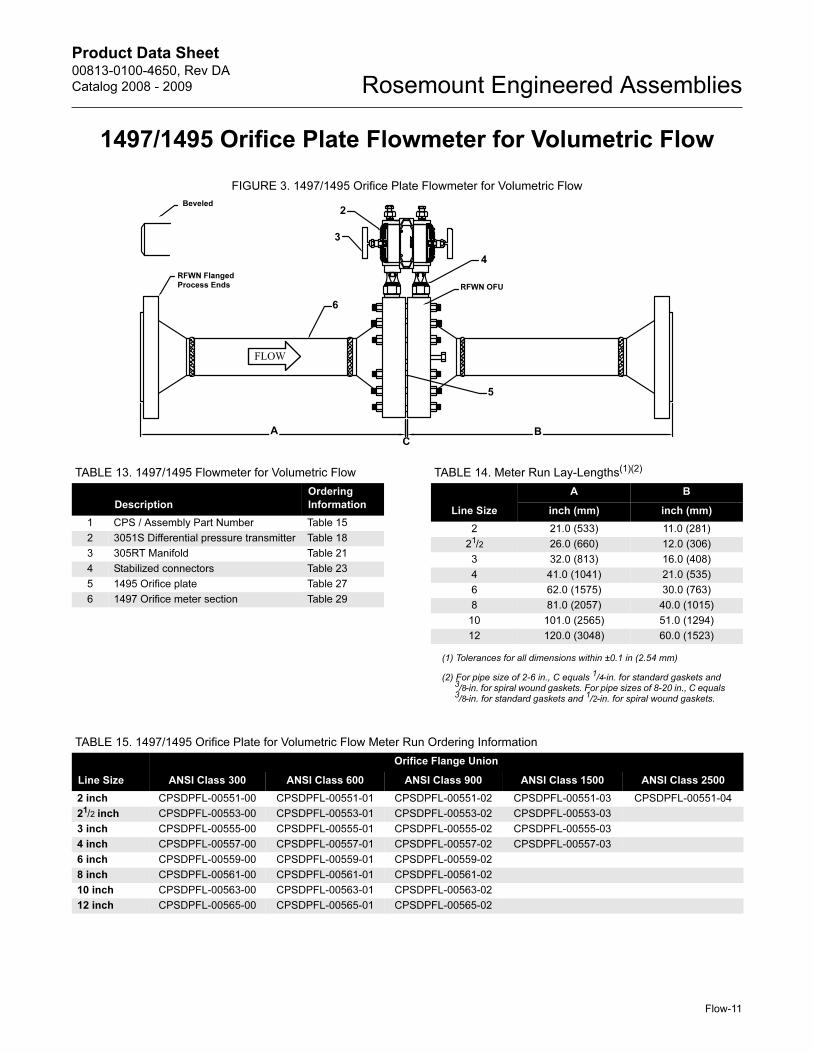
1497/1495 Orifice Plate Flowmeter for Volumetric Flow
FIGURE 3. 1497/1495 Orifice Plate Flowmeter for Volumetric Flow
6
4
5
RFWN Flanged
Process Ends
3
2Beveled
RFWN OFU
AC
B
TABLE 13. 1497/1495 Flowmeter for Volumetric Flow
Description
Ordering
Information
1 CPS / Assembly Part Number Table 15
2 3051S Differential pressure transmitter Table 18
3 305RT Manifold Table 21
4 Stabilized connectors Table 23
5 1495 Orifice plate Table 27
6 1497 Orifice meter section Table 29
TABLE 14. Meter Run Lay-Lengths(1)(2)
Line Size
A B
inch (mm) inch (mm)
2 21.0 (533) 11.0 (281)
21/2 26.0 (660) 12.0 (306)
3 32.0 (813) 16.0 (408)
4 41.0 (1041) 21.0 (535)
6 62.0 (1575) 30.0 (763)
8 81.0 (2057) 40.0 (1015)
10 101.0 (2565) 51.0 (1294)
12 120.0 (3048) 60.0 (1523)
(1) Tolerances for all dimensions within ±0.1 in (2.54 mm)
(2) For pipe size of 2-6 in., C equals 1/4-in. for standard gaskets and 3/8-in. for spiral wound gaskets. For pipe sizes of 8-20 in., C equals 3/8-in. for standard gaskets and 1/2-in. for spiral wound gaskets.
TABLE 15. 1497/1495 Orifice Plate for Volumetric Flow Meter Run Ordering Information
Line Size
Orifice Flange Union
ANSI Class 300 ANSI Class 600 ANSI Class 900 ANSI Class 1500 ANSI Class 2500
2 inch CPSDPFL-00551-00 CPSDPFL-00551-01 CPSDPFL-00551-02 CPSDPFL-00551-03 CPSDPFL-00551-04
21/2 inch CPSDPFL-00553-00 CPSDPFL-00553-01 CPSDPFL-00553-02 CPSDPFL-00553-03
3 inch CPSDPFL-00555-00 CPSDPFL-00555-01 CPSDPFL-00555-02 CPSDPFL-00555-03
4 inch CPSDPFL-00557-00 CPSDPFL-00557-01 CPSDPFL-00557-02 CPSDPFL-00557-03
6 inch CPSDPFL-00559-00 CPSDPFL-00559-01 CPSDPFL-00559-02
8 inch CPSDPFL-00561-00 CPSDPFL-00561-01 CPSDPFL-00561-02
10 inch CPSDPFL-00563-00 CPSDPFL-00563-01 CPSDPFL-00563-02
12 inch CPSDPFL-00565-00 CPSDPFL-00565-01 CPSDPFL-00565-02
Product Data Sheet00813-0100-4650, Rev DA
Catalog 2008 - 2009Rosemount Engineered Assemblies
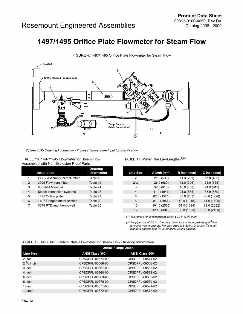
1497/1495 Orifice Plate Flowmeter for Steam Flow
FIGURE 4. 1497/1495 Orifice Plate Flowmeter for Steam Flow
TABLE 16. 1497/1495 Flowmeter for Steam Flow
Assembled with Non Explosion-Proof Parts
TABLE 17. Meter Run Lay-Lengths(1)(2)
DescriptionOrdering
Information Line Size A inch (mm) B inch (mm) C inch (mm)
1 CPS / Assembly Part Number Table 18 2 21.0 (533) 11.0 (281) 17.0 (433)
2 3095 Flow transmitter Table 19 21/2 26.0 (660) 12.0 (306) 21.0 (535)
3 0305RM Manifold Table 21 3 32.0 (813) 16.0 (408) 24.0 (611)
4 Steam connection systems Table 25 4 41.0 (1041) 21.0 (535) 33.0 (839)
5 1495 Orifice plate Table 27 6 62.0 (1575) 30.0 (763) 48.0 (1220)
6 1497 Flanged meter section Table 29 8 81.0 (2057) 40.0 (1015) 64.0 (1625)
7 0078 RTD and thermowell Table 30 10 101.0 (2565) 51.0 (1394) 82.0 (2082)
12 120.0 (3048) 60.0 (1523) 96.0 (2438)
(1) Tolerances for all dimensions within ±0.1 in (2.54 mm).
(2) For pipe size of 2-6 in., D equals 1/4-in. for standard gaskets and 3/8-in. for spiral wound gaskets. For pipe sizes of 8-20 in., D equals 3/8-in. for standard gaskets and 1/2-in. for spiral wound gaskets.
5
4
A C
B
6
RFWN Flanged Process Ends
3
2
7
Temp. Sensor Cable Connection*
(*) See 3095 Ordering Information - Process Temperature Input for specification.
Beveled
D
TABLE 18. 1497/1495 Orifice Plate Flowmeter for Steam Flow Ordering Information
Orifice Flange Union
Line Size ANSI Class 300 ANSI Class 600
2 inch CPSDPFL-00574-00 CPSDPFL-00574-02
2 1/2 inch CPSDPFL-00566-00 CPSDPFL-00566-02
3 inch CPSDPFL-00567-00 CPSDPFL-00567-02
4 inch CPSDPFL-00568-00 CPSDPFL-00568-02
6 inch CPSDPFL-00569-00 CPSDPFL-00569-02
8 inch CPSDPFL-00570-00 CPSDPFL-00570-02
10 inch CPSDPFL-00571-00 CPSDPFL-00571-02
12 inch CPSDPFL-00572-00 CPSDPFL-00572-02
Flow-12
Product Data Sheet00813-0100-4650, Rev DA
Catalog 2008 - 2009 Rosemount Engineered Assemblies
Flow-13
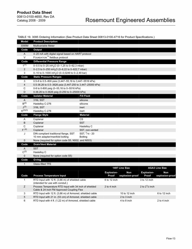
TABLE 19. 3095 Ordering Information (See Product Data Sheet 00813-0100-4716 for Product Specifications.)
Model Product Description
3095M Multivariable Meter
Code Output
A 4–20 mA with digital signal based on HART protocol
V FOUNDATION™ fieldbus protocol
Code Differential Pressure Range
1(1) 0–0.5 to 0–25 inH2O (0–1,25 to 0–62,3 mbar)
2 0–2.5 to 0–250 inH2O (0–6,22 to 0–622,7 mbar)
3 0–10 to 0–1000 inH2O (0–0,0249 to 0–2,49 bar)
Code Static Pressure Ranges
3 0.5-8 to 0.5–800 psia (3,447–55,16 to 3,447–5516 kPa)
4 0.5-36.26 to 0.5–3626 psia (3,447-250 to 3,447–25000 kPa)
C 0-8 to 0-800 psig (0–55,16 to 0–5516 kPa)
D 0-36.26 to 0-3626 psig (0-250 to 0–25000 kPa)
Code Isolator Material Fill Fluid
A 316L SST silicone
B(2) Hastelloy C-276 silicone
J(3) 316L SST inert
K(2)(3) Hastelloy C-276 inert
Code Flange Style Material
A Coplanar CS
B Coplanar SST
C Coplanar Hastelloy C
F (4) Coplanar SST, non-vented
J DIN compliant traditional flange, SST
10 mm adapter/manifold bolting
SST, 7/16 - 20
Bolting
0 None (required for option code S5, N502, and N503)
Code Drain/Vent Material
A SST
C(2) Hastelloy C
0 None (required for option code S5)
Code O-ring
1 Glass-filled TFE
1497 Line Size AGA3 Line Size
Code Process Temperature Input
Explosion-
Proof
Non
explosion-proof
Explosion-
Proof
Non
explosion-proof
1 RTD Input with 12 ft. (3,66 m) of shielded cable
(intended for use with conduit.)
6 to 12 inch 3 to 12 inch
Z Process Temperature RTD Input with 34 inch of shielded
Cable & 24 inch FM Approved Coupling Flex
2 to 4 inch 2 to 21/2 inch
3 RTD Input with 12 ft. (3,66 m) of Armored, shielded cable 10 to 12 inch 6 to 12 inch
5 RTD Input with 21 in. (53 cm) of Armored, shielded cable 2 to 3 inch
6 RTD Input with 4 ft. (1,22 m) of Armored, shielded cable 4 to 8 inch 2 to 4 inch

Product Data Sheet00813-0100-4650, Rev DA
Catalog 2008 - 2009Rosemount Engineered Assemblies
Code Transmitter Housing Material Conduit Entry Size
A Polyurethane-covered aluminum ½–14 NPT
B Polyurethane-covered aluminum M20 � 1.5 (CM20)
C Polyurethane-covered aluminum PG 13.5
J SST ½–14 NPT
K SST M20 � 1.5 (CM20)
L SST PG 13.5
Code Terminal Block
A Standard
B With integral transient protection
Code Display
0 None
1 LCD Display
Code Bracket
0 None
Code Bolts
0 CS bolts
1 Austenitic 316 SST bolts
N None (Required for Option Code S5)
Code Product Certifications (Transmitter only)
0 None
A FM Explosion-Proof
B FM Explosion-Proof, Intrinsically Safe, and Non-Incendive (combination of A and J)
C CSA Explosion-Proof
D CSA Explosion-Proof, Intrinsically Safe, and Non-Incendive (combination of C and K)
J FM Intrinsically Safe
K CSA Intrinsically Safe
V FM FISCO Intrinsically Safe; for FOUNDATION fieldbus protocol only
W CSA FISCO Intrinsically Safe; for FOUNDATION fieldbus protocol only
Y IECEx FISCO Intrinsically Safe
4 IECEx Intrinsically Safe
5 IECEx Type n
Code Engineered Measurement Solution (EMS)
B(5) Fully Compensated Mass Flow and Measured Variables (DP, P, and T) with HART or FOUNDATION fieldbus.
V Process Variable Measurement (DP, P and T) only for FOUNDATION fieldbus protocol
Code Manifolds
S5 Assemble to Rosemount 305 Integral Manifold
(Requires integral manifold model number – see Table 21)
S6 Assemble to Rosmeount 304 manifold or connection system
TABLE 19. 3095 Ordering Information (See Product Data Sheet 00813-0100-4716 for Product Specifications.)
Flow-14

Product Data Sheet00813-0100-4650, Rev DA
Catalog 2008 - 2009 Rosemount Engineered Assemblies
Code Options
Performance Class
U3(6) Ultra for Flow: ±0.05% DP reading accuracy, up to 100:1 rangedown, 10 year stability, limited 12 year warranty
PlantWeb Control Functionality
A01(7) FOUNDATION fieldbus Advanced Control Function Block Suite
Custom Configuration
C2 Custom Flow Configuration (Requires completed Configuration Data Sheet 00806-0100-4716.)
Calibration Data Sheet
Q4 (8) Inspection Certificate for Calibration Data
Material Traceability Certification
Q8 (9) Material Inspection Certificate per EN 10204 3.1B
(1) Available only with 3 or C sensor modules and A 316L SST/silicone, Isolator/Fill Fluid option.
(2) Materials of Construction comply with metallurgical requirements highlighted within NACE MR0175/ISO 15156 sour oil field production environments. Environmental limits apply to certain materials. Consult latest standard for details. Selected materials also conform to NACE MR0103 for sour refining environments.
(3) Only available with C or D Gage Sensor Modules.
(4) Requires that Drain/Vent Material Code set to 0 (none).
(5) Requires Rosemount 3095 Engineering Software Assistant to configure mass flow.
(6) Ultra for Flow applicable for DP ranges 2 and 3 with SST isolator material and silicone fill fluid only.
(7) Function Blocks include: Arithmetic, Integrator, Analog Output, Signal Characterizer, Control Selector, and Output Selector.
(8) Must be order to meet 40CFR 75 Appendix D and E standards when ordering AGA Report Number 3 / API 14.3.2.
(9) This option is available for the sensor module housing, Coplanar and Coplanar flange adapters.
TABLE 19. 3095 Ordering Information (See Product Data Sheet 00813-0100-4716 for Product Specifications.)
Flow-15
Product Data Sheet00813-0100-4650, Rev DA
Catalog 2008 - 2009Rosemount Engineered Assemblies
Flow-16
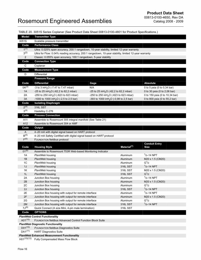
TABLE 20. 3051S Series Coplanar (See Product Data Sheet 00813-0100-4801 for Product Specifications.)
Model Transmitter Type
3051S Scalable pressure transmitter
Code Performance Class
1(1) Ultra: 0.025% span accuracy, 200:1 rangedown, 10-year stability, limited 12-year warranty
3(2) Ultra for Flow: 0.04% reading accuracy, 200:1 rangedown, 10-year stability, limited 12-year warranty
2 Classic: 0.055% span accuracy, 100:1 rangedown, 5-year stability
Code Connection Type
C Coplanar
Code Measurement Type
D Differential
Code
Pressure Range
Differential Gage Absolute
0A(3) -3 to 3 inH2O (-7,47 to 7,47 mbar) N/A 0 to 5 psia (0 to 0,34 bar)
1A -25 to 25 inH2O (-62,2 to 62,2 mbar) -25 to 25 inH2O (-62,2 to 62,2 mbar) 0 to 30 psia (0 to 2,06 bar)
2A -250 to 250 inH2O (-623 to 623 mbar) -250 to 250 inH2O (-623 to 623 mbar) 0 to 150 psia (0 to 10,34 bar)
3A -1000 to 1000 inH2O (-2,5 to 2,5 bar) -393 to 1000 inH2O (-0,98 to 2,5 bar) 0 to 800 psia (0 to 55,2 bar)
Code Isolating Diaphragm
2(4) 316L SST
3(4) Hastelloy C-276
Code Process Connection
A11 Assemble to Rosemount 305 integral manifold (See Table 21)
A12 Assemble to Rosemount 304 or AMF
Code Output
A 4–20 mA with digital signal based on HART protocol
B(5) 4–20 mA Safety Certified with digital signal based on HART protocol
F(6) FOUNDATION fieldbus protocol
Code Housing Style Material(7)Conduit Entry
Size
01(8) Assemble to Rosemount 753R Web-based Monitoring Indicator
1A PlantWeb housing Aluminum 1/2–14 NPT
1B PlantWeb housing Aluminum M20 x 1.5 (CM20)
1C PlantWeb housing Aluminum G1/2
1J PlantWeb housing 316L SST 1/2–14 NPT
1K PlantWeb housing 316L SST M20 x 1.5 (CM20)
1L PlantWeb housing 316L SST G1/2
2A Junction Box housing Aluminum 1/2–14 NPT
2B Junction Box housing Aluminum M20 x 1.5 (CM20)
2C Junction Box housing Aluminum G1/2
2J Junction Box housing 316L SST 1/2–14 NPT
2E Junction Box housing with output for remote interface Aluminum 1/2–14 NPT
2F Junction Box housing with output for remote interface Aluminum M20 x 1.5 (CM20)
2G Junction Box housing with output for remote interface Aluminum G1/2
2M Junction Box housing with output for remote interface 316L SST 1/2–14 NPT
7J(9) Quick Connect (A size Mini, 4-pin male termination) 316L SST
Code OPTIONS
PlantWeb Control Functionality
A01(10) FOUNDATION fieldbus Advanced Control Function Block Suite
PlantWeb Diagnostic Functionality
D01(10) FOUNDATION fieldbus Diagnostics Suite
DA1(11) HART Diagnostics Suite
PlantWeb Enhanced Measurement Functionality
H01(10)(12) Fully Compensated Mass Flow Block
Product Data Sheet00813-0100-4650, Rev DA
Catalog 2008 - 2009 Rosemount Engineered Assemblies
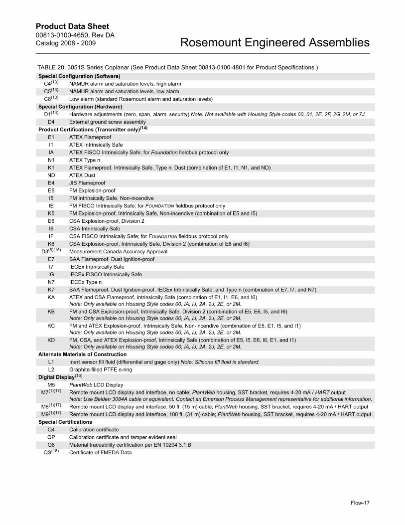
Special Configuration (Software)
C4(13) NAMUR alarm and saturation levels, high alarm
C5(13) NAMUR alarm and saturation levels, low alarm
C8(13) Low alarm (standard Rosemount alarm and saturation levels)
Special Configuration (Hardware)
D1(13) Hardware adjustments (zero, span, alarm, security) Note: Not available with Housing Style codes 00, 01, 2E, 2F, 2G, 2M, or 7J.
D4 External ground screw assembly
Product Certifications (Transmitter only)(14)
E1 ATEX Flameproof
I1 ATEX Intrinsically Safe
IA ATEX FISCO Intrinsically Safe; for Foundation fieldbus protocol only
N1 ATEX Type n
K1 ATEX Flameproof, Intrinsically Safe, Type n, Dust (combination of E1, I1, N1, and ND)
ND ATEX Dust
E4 JIS Flameproof
E5 FM Explosion-proof
I5 FM Intrinsically Safe, Non-incendive
IE FM FISCO Intrinsically Safe; for FOUNDATION fieldbus protocol only
K5 FM Explosion-proof, Intrinsically Safe, Non-incendive (combination of E5 and I5)
E6 CSA Explosion-proof, Division 2
I6 CSA Intrinsically Safe
IF CSA FISCO Intrinsically Safe; for FOUNDATION fieldbus protocol only
K6 CSA Explosion-proof, Intrinsically Safe, Division 2 (combination of E6 and I6)
D3(5)(15) Measurement Canada Accuracy Approval
E7 SAA Flameproof, Dust Ignition-proof
I7 IECEx Intrinsically Safe
IG IECEx FISCO Intrinsically Safe
N7 IECEx Type n
K7 SAA Flameproof, Dust Ignition-proof, IECEx Intrinsically Safe, and Type n (combination of E7, I7, and N7)
KA ATEX and CSA Flameproof, Intrinsically Safe (combination of E1, I1, E6, and I6)
Note: Only available on Housing Style codes 00, IA, IJ, 2A, 2J, 2E, or 2M.
KB FM and CSA Explosion-proof, Intrinsically Safe, Division 2 (combination of E5, E6, I5, and I6)
Note: Only available on Housing Style codes 00, IA, IJ, 2A, 2J, 2E, or 2M.
KC FM and ATEX Explosion-proof, Intrinsically Safe, Non-incendive (combination of E5, E1, I5, and I1)
Note: Only available on Housing Style codes 00, IA, IJ, 2A, 2J, 2E, or 2M.
KD FM, CSA, and ATEX Explosion-proof, Intrinsically Safe (combination of E5, I5, E6, I6, E1, and I1)
Note: Only available on Housing Style codes 00, IA, IJ, 2A, 2J, 2E, or 2M.
Alternate Materials of Construction
L1 Inert sensor fill fluid (differential and gage only) Note: Silicone fill fluid is standard.
L2 Graphite-filled PTFE o-ring
Digital Display(16)
M5 PlantWeb LCD Display
M7(1)(17) Remote mount LCD display and interface, no cable; PlantWeb housing, SST bracket, requires 4-20 mA / HART output
Note: Use Belden 3084A cable or equivalent. Contact an Emerson Process Management representative for additional information.
M8(1)(17) Remote mount LCD display and interface, 50 ft. (15 m) cable; PlantWeb housing, SST bracket, requires 4-20 mA / HART output
M9(1)(17) Remote mount LCD display and interface, 100 ft. (31 m) cable; PlantWeb housing, SST bracket, requires 4-20 mA / HART output
Special Certifications
Q4 Calibration certificate
QP Calibration certificate and tamper evident seal
Q8 Material traceability certification per EN 10204 3.1.B
QS(18) Certificate of FMEDA Data
TABLE 20. 3051S Series Coplanar (See Product Data Sheet 00813-0100-4801 for Product Specifications.)
Flow-17

Product Data Sheet00813-0100-4650, Rev DA
Catalog 2008 - 2009Rosemount Engineered Assemblies
Terminal Blocks
T1(19) Transient terminal block
T2(20) Terminal block with WAGO® spring clamp terminals
T3(20) Transient terminal block with WAGO spring clamp terminals
Conduit Electrical Connector
GE(21) M12, 4-pin, Male Connector (eurofast®)
GM(21) A size Mini, 4-pin, Male Connector (minifast®)
(1) Not available with Output code B.
(2) Not available with output code B or Housing code 01. This option is only available with range codes 2A and 3A, 316L SST isolating diaphragm and silicone fill fluid.
(3) 3051S_CD0 is only available with traditional flange, 316 SST diaphragm material, silicone fill fluid and bolting option L4.
(4) Materials of Construction comply with metallurgical requirements highlighted within NACE MR0175/ISO 15156 sour oil field production environments. Environmental limits apply to certain materials. Consult latest standard for details. Selected materials also conform to NACE MR0103 for sour refining environments.
(5) Requires PlantWeb housing and Hardware Adjustments option code D1. For the 3051S SIS Safety Transmitter, rangedown is limited to 10:1 on all models with the exception of range 0. The 3051S2CD0 is limited to 2:1 rangedown, the 3051S2CA0 is limited to 5:1 rangedown.
(6) Requires PlantWeb housing.
(7) Material specified is cast as follows: CF-8M is the cast version of 316 SST, CF-3M is the cast version of 316L SST, CW-12MW is the cast version of Hastelloy C-276, M-30C is the cast version of Monel 400. For housing, material is aluminum with polyurethane paint.
(8) Available with output code A only. Not available with approvals. See Rosemount 753R Product Data Sheet, 00813-0100-4379, to specify Web-based Monitoring Indicator. Does not integrate into plant host systems.
(9) Available with output code A only. Available approvals are FM Intrinsically Safe, Non-incendive (option code I5) or ATEX Intrinsically Safe (option code I1). Contact an Emerson Process Management representative for additional information.
(10) Requires PlantWeb housing and output code F.
(11) Requires PlantWeb housing and output code A. Includes Hardware Adjustments as standard. Contact an Emerson Process Management representative regarding availability.
(12) Requires Rosemount 3095 Engineering Assistant to configure.
(13) Not available with output code F or Housing code 01.
(14) Valid when SuperModule Platform and housing have equivalent approvals.
(15) Limited availability depending on transmitter type and range. Contact an Emerson Process Management representative for additional information.
(16) Not available with Housing code 01 or 7J.
(17) Not available with output code F, Housing code 01, or option code DA1.
(18) Not available with Housing code 01.
(19) Not available with Housing code 00, 01, or 7J.
(20) Available with output code A and PlantWeb housing only.
(21) Not available with Housing code 00, 01, or 7J. Available with Intrinsically Safe approvals only. For FM Intrinsically Safe, Non-incendive approval (option code I5) or FM FISCO Intrinsically Safe approval (option code IE), install in accordance with Rosemount drawing 03151-1009 to maintain NEMA 4X rating.
TABLE 20. 3051S Series Coplanar (See Product Data Sheet 00813-0100-4801 for Product Specifications.)
Flow-18
Product Data Sheet00813-0100-4650, Rev DA
Catalog 2008 - 2009 Rosemount Engineered Assemblies
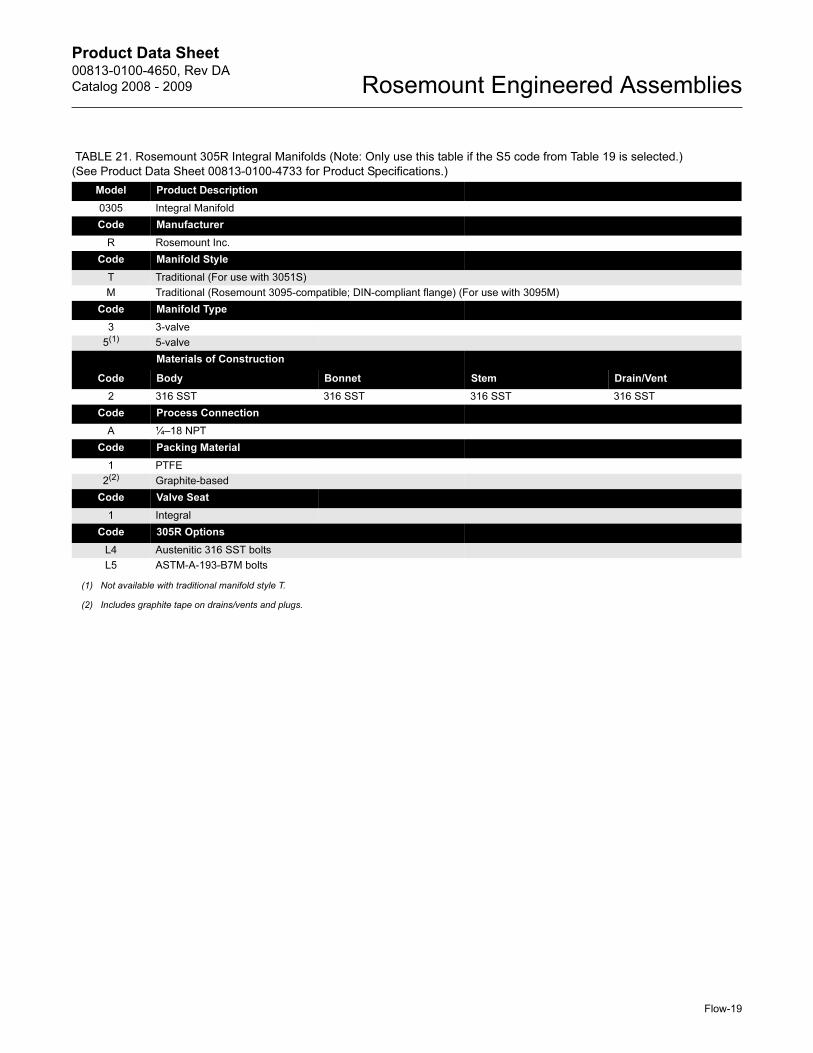
TABLE 21. Rosemount 305R Integral Manifolds (Note: Only use this table if the S5 code from Table 19 is selected.)
(See Product Data Sheet 00813-0100-4733 for Product Specifications.)
Model Product Description
0305 Integral Manifold
Code Manufacturer
R Rosemount Inc.
Code Manifold Style
T Traditional (For use with 3051S)
M Traditional (Rosemount 3095-compatible; DIN-compliant flange) (For use with 3095M)
Code Manifold Type
3 3-valve
5(1) 5-valve
Materials of Construction
Code Body Bonnet Stem Drain/Vent
2 316 SST 316 SST 316 SST 316 SST
Code Process Connection
A ¼–18 NPT
Code Packing Material
1 PTFE
2(2) Graphite-based
Code Valve Seat
1 Integral
Code 305R Options
L4 Austenitic 316 SST bolts
L5 ASTM-A-193-B7M bolts
(1) Not available with traditional manifold style T.
(2) Includes graphite tape on drains/vents and plugs.
Flow-19
Product Data Sheet00813-0100-4650, Rev DA
Catalog 2008 - 2009Rosemount Engineered Assemblies
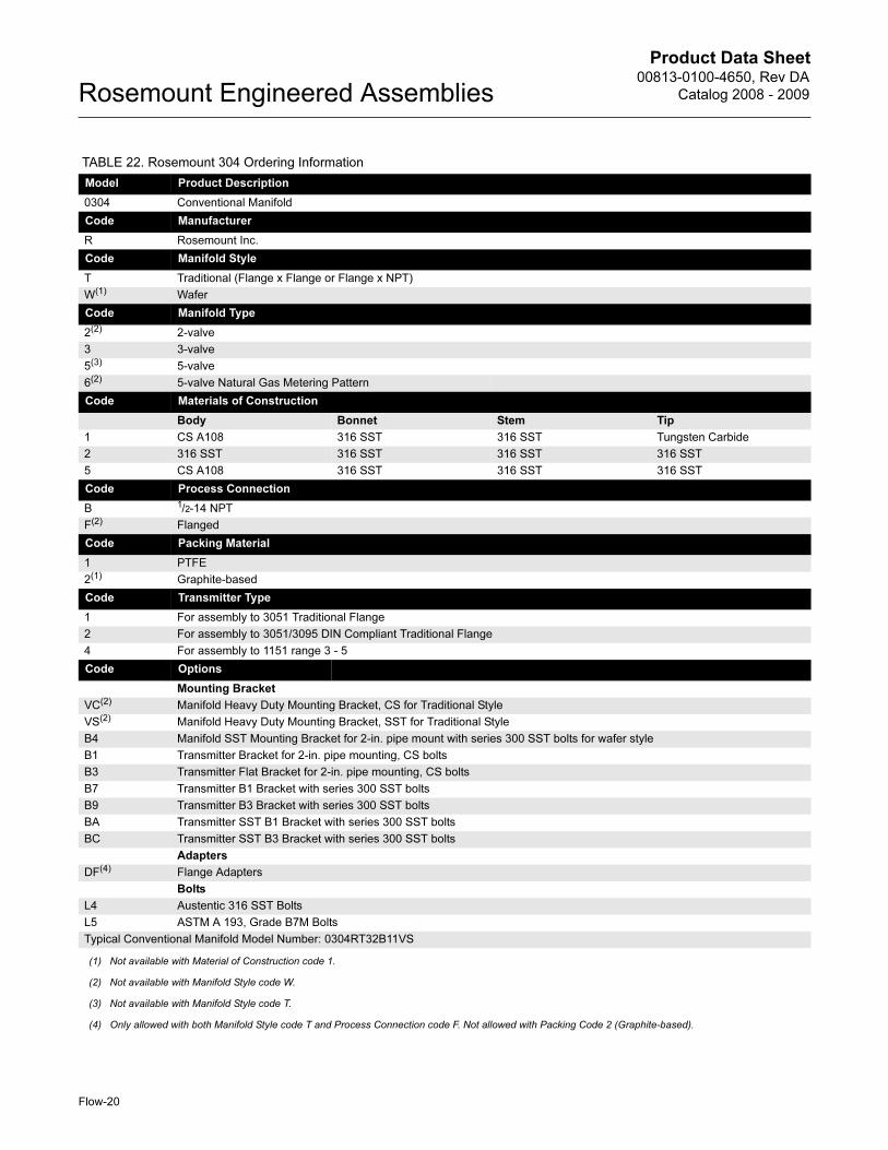
TABLE 22. Rosemount 304 Ordering Information
Model Product Description
0304 Conventional Manifold
Code Manufacturer
R Rosemount Inc.
Code Manifold Style
T Traditional (Flange x Flange or Flange x NPT)
W(1) Wafer
Code Manifold Type
2(2) 2-valve
3 3-valve
5(3) 5-valve
6(2) 5-valve Natural Gas Metering Pattern
Code Materials of Construction
Body Bonnet Stem Tip
1 CS A108 316 SST 316 SST Tungsten Carbide
2 316 SST 316 SST 316 SST 316 SST
5 CS A108 316 SST 316 SST 316 SST
Code Process Connection
B 1/2-14 NPT
F(2) Flanged
Code Packing Material
1 PTFE
2(1) Graphite-based
Code Transmitter Type
1 For assembly to 3051 Traditional Flange
2 For assembly to 3051/3095 DIN Compliant Traditional Flange
4 For assembly to 1151 range 3 - 5
Code Options
Mounting Bracket
VC(2) Manifold Heavy Duty Mounting Bracket, CS for Traditional Style
VS(2) Manifold Heavy Duty Mounting Bracket, SST for Traditional Style
B4 Manifold SST Mounting Bracket for 2-in. pipe mount with series 300 SST bolts for wafer style
B1 Transmitter Bracket for 2-in. pipe mounting, CS bolts
B3 Transmitter Flat Bracket for 2-in. pipe mounting, CS bolts
B7 Transmitter B1 Bracket with series 300 SST bolts
B9 Transmitter B3 Bracket with series 300 SST bolts
BA Transmitter SST B1 Bracket with series 300 SST bolts
BC Transmitter SST B3 Bracket with series 300 SST bolts
Adapters
DF(4) Flange Adapters
Bolts
L4 Austentic 316 SST Bolts
L5 ASTM A 193, Grade B7M Bolts
Typical Conventional Manifold Model Number: 0304RT32B11VS
(1) Not available with Material of Construction code 1.
(2) Not available with Manifold Style code W.
(3) Not available with Manifold Style code T.
(4) Only allowed with both Manifold Style code T and Process Connection code F. Not allowed with Packing Code 2 (Graphite-based).
Flow-20
Product Data Sheet00813-0100-4650, Rev DA
Catalog 2008 - 2009 Rosemount Engineered Assemblies
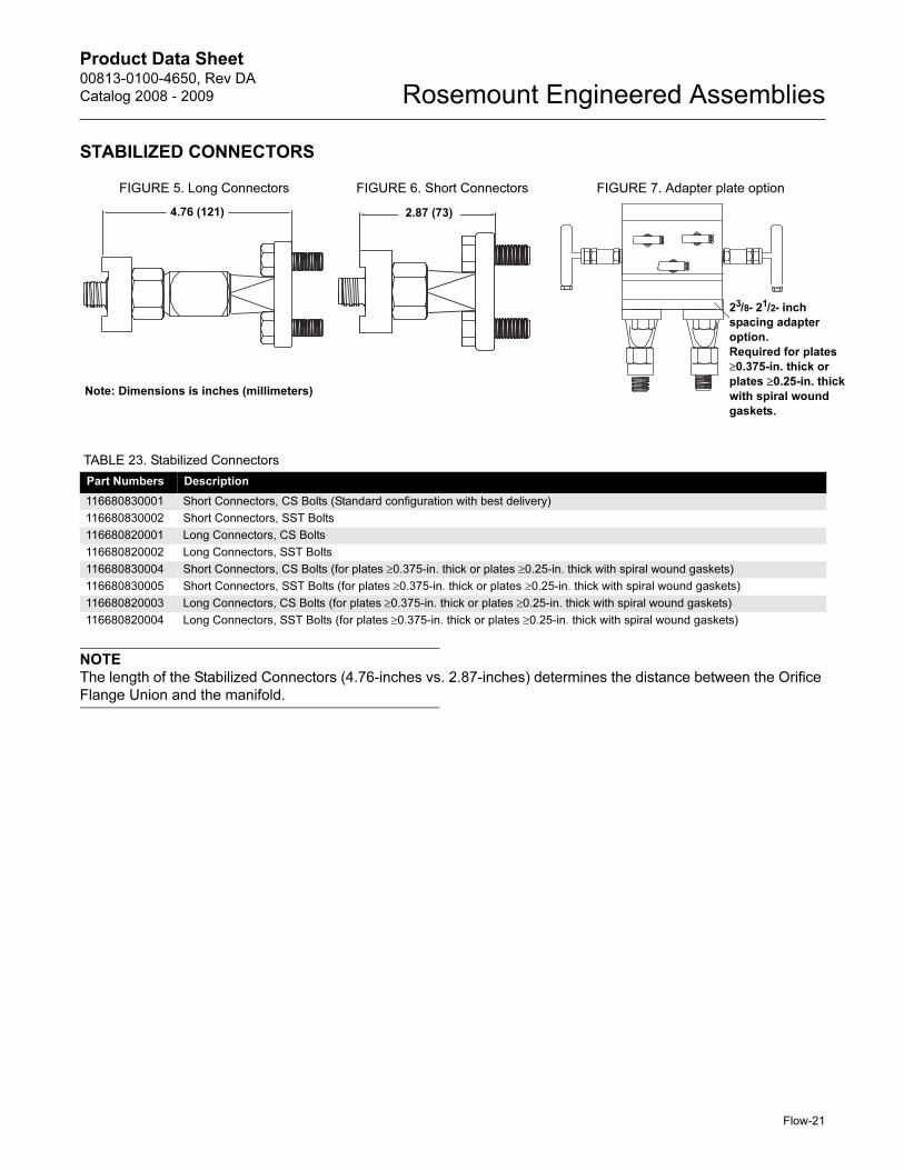
STABILIZED CONNECTORS
NOTE
The length of the Stabilized Connectors (4.76-inches vs. 2.87-inches) determines the distance between the Orifice
Flange Union and the manifold.
FIGURE 5. Long Connectors FIGURE 6. Short Connectors FIGURE 7. Adapter plate option
4.76 (121)
Note: Dimensions is inches (millimeters)
2.87 (73)
23/8- 21/2- inch
spacing adapter
option.
Required for plates
≥0.375-in. thick or
plates ≥0.25-in. thick
with spiral wound
gaskets.
TABLE 23. Stabilized Connectors
Part Numbers Description
116680830001 Short Connectors, CS Bolts (Standard configuration with best delivery)
116680830002 Short Connectors, SST Bolts
116680820001 Long Connectors, CS Bolts
116680820002 Long Connectors, SST Bolts
116680830004 Short Connectors, CS Bolts (for plates ≥0.375-in. thick or plates ≥0.25-in. thick with spiral wound gaskets)
116680830005 Short Connectors, SST Bolts (for plates ≥0.375-in. thick or plates ≥0.25-in. thick with spiral wound gaskets)
116680820003 Long Connectors, CS Bolts (for plates ≥0.375-in. thick or plates ≥0.25-in. thick with spiral wound gaskets)
116680820004 Long Connectors, SST Bolts (for plates ≥0.375-in. thick or plates ≥0.25-in. thick with spiral wound gaskets)
Flow-21
Product Data Sheet00813-0100-4650, Rev DA
Catalog 2008 - 2009Rosemount Engineered Assemblies
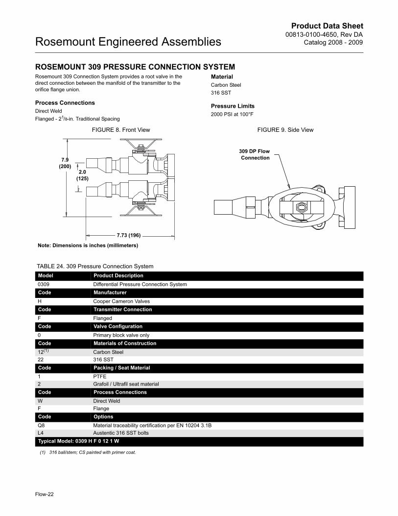
ROSEMOUNT 309 PRESSURE CONNECTION SYSTEMRosemount 309 Connection System provides a root valve in the
direct connection between the manifold of the transmitter to the
orifice flange union.
Process Connections
Direct Weld
Flanged - 21/8-in. Traditional Spacing
Material
Carbon Steel
316 SST
Pressure Limits
2000 PSI at 100°F
FIGURE 8. Front View FIGURE 9. Side View
7.73 (196)
Note: Dimensions is inches (millimeters)
7.9
(200)2.0
(125)
309 DP Flow
Connection
TABLE 24. 309 Pressure Connection System
Model Product Description
0309 Differential Pressure Connection System
Code Manufacturer
H Cooper Cameron Valves
Code Transmitter Connection
F Flanged
Code Valve Configuration
0 Primary block valve only
Code Materials of Construction
12(1) Carbon Steel
22 316 SST
Code Packing / Seat Material
1 PTFE
2 Grafoil / Ultrafil seat material
Code Process Connections
W Direct Weld
F Flange
Code Options
Q8 Material traceability certification per EN 10204 3.1B
L4 Austentic 316 SST bolts
Typical Model: 0309 H F 0 12 1 W
(1) 316 ball/stem; CS painted with primer coat.
Flow-22
Product Data Sheet00813-0100-4650, Rev DA
Catalog 2008 - 2009 Rosemount Engineered Assemblies
STEAM CONNECTION SYSTEM
Piping Specification
/CS-1
Piping Material
ASTM A106 GR B Carbon Steel:
Fittings - ASTM A105 Class 3000
Welded Specification
/SW-2-2
Welded Type
Socket Weld
Process Connection
Schedule 80 - Standard
Inst Detail Piping
Schedule 80 - Standard
Valve Specification
Valve Code
/V1
Root Valve / Vent / Drain Valve
Description
VELAN -Class 800 Gate Valves
(Root W-2184W-02TY)/(D/V C-218W-02TY)
Body Material
Forged Steel
Seat Material
Stellite 6
Packing
Graphite
Bypass Manifold Valve
Description
M2-110SRT PGI Bypass Manifold
Body Material
Forged Steel
Ball Material
Ceramic Rising Stem Ball
Packing
PTFE
Bracket Specification
/Line Size-V-X
Temperature Range
315 to 380°C
CS Pipe
Pipe clamp is painted CS. Thermal isolators (2) are hot dipped
galvanized CS.
FIGURE 10. Steam Connection System
TABLE 25. Steam connection System
Part Number Connection System Line Size
A013340001-0144 3413-10/CS-1/SW-2-2/V1/2-V-X// 2-inch
A013340001-0145 3413-10/CS-1/SW-2-2/V1/3-V-X// 21/2- and 3-inch
A013340001-0146 3413-10/CS-1/SW-2-2/V1/4-V-X// 4-inch
A013340001-0147 3413-10/CS-1/SW-2-2/V1/6-V-X// 6-inch
A013340001-0148 3413-10/CS-1/SW-2-2/V1/8-V-X// 8-inch
A013340001-0149 3413-10/CS-1/SW-2-2/V1/10-V-X// 10-inch
A013340001-0150 3413-10/CS-1/SW-2-2/V1/12-V-X// 12-inch
Flow-23
Product Data Sheet00813-0100-4650, Rev DA
Catalog 2008 - 2009Rosemount Engineered Assemblies
Flow-24
TABLE 26. Rosemount 1595 Orifice Plate Ordering Table
(See Product Data Sheet 00813-0100-4828 for Product Specifications.)
Model Product Description
1595 Conditioning Orifice Plate
Code Plate Type
P Paddle, Square Edged
Code Line Size
020 2-in. (50 mm)
030 3-in. (76 mm)
040 4-in. (100 mm)
060 6-in. (150 mm)
080 8-in. (200 mm)
100 10-in. (250 mm)
120 12-in. (300 mm)
140 14-in. (350 mm)
160 16-in. (400 mm)
180 18-in. (450 mm)
200 20-in. (500 mm)
Code Flange Rating
A3 ANSI Class 300 Raised Face
A6 ANSI Class 600 Raised Face
A9 ANSI Class 900 Raised Face
AF ANSI Class 1500 Raised Face
AT ANSI Class 2500 Raised Face
Code Material Type
S 316/316L Stainless Steel
L 304/304L Stainless Steel
M Monel®
H Hastelloy® C-276
Code Orifice Plate Thickness (1)
A 0.125-in. (default for Line Sizes 2 to 4-in. (50 mm to 100 mm))
B 0.250-in. (default for Line Sizes 6 to 12-in. (150 to 300 mm))
C 0.375-in. (default for line sizes 14 to 20-in. (350 to 500 mm))
Code Beta Ratio
020 0.20 Beta Ratio
040 0.40 Beta Ratio
065 0.65 Beta Ratio (0.60 beta ratio for Line Size option 020 only)
Code Options
Flow Calibration
WC Discharge Coefficient Verification (3 points)
WD Discharge Coefficient Verification (full 10 points)
Special Inspection
QC1 Visual and dimensional Inspection with certification
QC7 Inspection and performance certificate
Material Traceability Certification
Q8 Material Certification per ISO 10474 3.1-B and EN 10204 3.1.B
Country Certification
J1 Canadian Registration
Typical Model Number: 1595 P 060 A3 S A 040
(1) Tolerances for all dimensions within ±0.1 in (2.54 mm)

Product Data Sheet00813-0100-4650, Rev DA
Catalog 2008 - 2009 Rosemount Engineered Assemblies
TABLE 27. Rosemount 1495 Orifice Plate Ordering Table
(See Product Data Sheet 00813-0100-4792 for Product Specifications.)
Model Product Description
1495 Orifice Plate Primary
Code Orifice Plate Type
PC Paddle, Concentric
Code Line Size
020 2-in. (50 mm)
025 2.5-in. (64 mm)
030 3-in. (80 mm)
040 4-in. (100 mm)
060 6-in. (150 mm)
080 8-in. (200 mm)
100 10-in. (250 mm)
120 12-in. (300 mm)
Code Flange Rating
A3 ANSI Class 300
A6 ANSI Class 600
A9 (1) ANSI Class 900
Code Orifice Plate Material Type
S 316/316L Stainless Steel
T DIN 1.4571 (316Ti Stainless Steel)
L 304/304L Stainless Steel
H Hastelloy® C-276
M Monel®
Code Plate Thickness(2)
A 0.125-in. (3.2 mm) – default for line size 2 to 6-in. (50 to 150 mm)
B 0.250-in. (6.35 mm) – default for line size 8 to 14-in. (200 to 350 mm)
Code Bore
XXXXX Bore (XXXXX = XX.XXX)
Code Options
BC Bore Calculation
Special Inspection
QC1 (3) Visual and dimensional inspection with certificate
QC7 Inspection and performance certificate
Material Traceability Certification
Q8 Material Certification per IS 10474 3.1-B and EN 10204 3.1.B
Typical Model Number: 1495 PC 040 A3 S A
(1) Not available for Steam Flow option.
(2) Tolerances for all dimensions within ±0.1 in (2.54 mm)
(3) Must be order to meet 40CFR 75 Appendix D and E standards when ordering AGA Report Number 3 / API 14.3.2.
Flow-25

Product Data Sheet00813-0100-4650, Rev DA
Catalog 2008 - 2009Rosemount Engineered Assemblies
BUY/RESALE AGA3 REPORT NUMBER 3 / API 14.3.2 COMPLIANT ORIFICE PLATE FLOWMETER SECTION
Material
Pipe: Carbon Steel ASTM A106 Grade B
Flanges: (ANSI B16.5): Carbon Steel ASTM A105
Studs: ASTM A193 Grade B7
Nuts: ASTM A193 Grade H2
Jackscrews: ASTM A307
Gaskets: Non-asbestos flat for ANSI Class 300. Spiral-wound for ANSI Class 600, 900, 1500, and 2500.
Pipe Plugs: ASTM A105
Pipe Schedule: Schedule Standard for ANSI Class 300 and 600. Schedule XS for ANSI Class 900, 1500, and 2500.
TABLE 28. Buy/Resale AGA3 Report Number 3 / API 14.3.2 Compliant Orifice Plate Meter Run
Model Product Description
AGA3 AGA3 Orifice Meter Run Section
Code Meter Section Material Type
C Carbon Steel
Code Line Size
020 2-in. (50 mm)
025 2.5-in. (64 mm)
030 3-in. (80 mm)
040 4-in. (100 mm)
060 6-in. (150 mm)
080 8-in. (200 mm)
100 10-in. (250 mm)
120 12-in. (300 mm)
Code Orifice Flange Rating
A3 ANSI Class 300
A6 ANSI Class 600
A9 (1) ANSI Class 900
AF ANSI Class 1500 (only available in line sizes 2-in. through 4-in.)
AT ANSI Class 2500 (only available in line size 2-in.)
Code Meter Section End Connections
B(2) Beveled (prepared for welding)
F Flanged (flange rating matches orifice flange rating)
G(3) Flanged, ANSI Class 150
Typical Part Number: AGA3 C 040 A3 F
(1) This option is only available with 10-in. and 12-in. line sizes when Meter Section End Connections option code B is selected.
(2) Prepared for welding process ends.Note: Flanged connections should be considered for vertical line applications to prevent possible flowmeter damage from weld splatter.
(3) This option is only available with orifice flange union rating code A3.
Flow-26
Product Data Sheet00813-0100-4650, Rev DA
Catalog 2008 - 2009 Rosemount Engineered Assemblies
TABLE 29. Rosemount 1497 Orifice Meter Section Ordering Table
(See Product Data Sheet 00813-0100-4792 for Product Specifications.)
Model Product Description
1497 Orifice Meter Section
Code Meter Section Type
WN Raised Face, Weld neck
Code Line Size
020 2-in. (50 mm)
025 21/2-in. (64 mm)
030 3-in. (80 mm)
040 4-in. (100 mm)
060 6-in. (150 mm)
080 8-in. (200 mm)
100 10-in. (250 mm)
120 12-in. (300 mm)
140(1) 14-in. (350 mm)
160(1) 16-in. (400 mm)
180(1) 18-in. (450 mm)
200(1) 20-in. (500 mm)
Code Flange Rating
A3 ANSI Class 300
A6 ANSI Class 600
A9(2) ANSI Class 900
AF(1)(2) ANSI Class 1500
AT(1)(2) ANSI Class 2500
Code Meter Section Material Type
C Carbon Steel
S 316/316L Stainless Steel
L 304/304L Stainless Steel
H Hastelloy® C-276
M Monel®
Pressure Tap Location / Type
F Flanged / 1/2-in. FNPT
G Flanged / 1/2-in. Socket Tap
Meter Section End Connections
B(3) Beveled (prepared for welding)
F Flanged (flange rating matches orifice flange rating)
G Flanged, ANSI 150#
T NPT Male Thread
Flow-27
Product Data Sheet00813-0100-4650, Rev DA
Catalog 2008 - 2009Rosemount Engineered Assemblies
Flow-28
Code Options
Alternate Pipe Schedule / Wall Thickness(4)
FA(5) Schedule 5S
FB(5) Schedule 10
FC(5) Schedule 10S
FD(5) Schedule 20
FE (5) Schedule 30
FF (5) Schedule 40
FG (5) Schedule 40S
FH (5) Schedule Standard (STD)
FI (5) Schedule 60
FJ (5) Schedule 80
FK (5) Schedule 80S
FL (5) Schedule Extra Strong (XS)
FM (5) Schedule 100
FN (5) Schedule 120
FP (5) Schedule 140
FQ (5) Schedule 160
FR (5) Schedule Double Extra Strong (XXS)
Temperature Taps (Note: Temperature Tap Option must match Thermowell size on page Flow-30)
TO Temperature Tap, fitting only, 1/2-in. NPT (For 2- through 3-inch line size only)
TQ Temperature Tap, fitting only, 3/4-in. NPT (For 4-inch line size only)
TR Temperature Tap, fitting only, 3/4-in. SW (For 2- through 4-inch line size only) (Steam Flow Assemblies Only)
TS Temperature Tap, fitting only, 1-in. SW (For 6- through 12-inch line size only) (Steam Flow Assemblies Only)
TT Temperature Tap, fitting only, 1-in. (25.4 mm) NPT (4) (For 6- through 20-inch line size only)
High Temperature Gaskets
G1(6) High Temperature Gaskets (spiral wound gaskets)
Alternate Bolting Material
SS 316 Stainless Steel Studs / Nuts
Hydrostatic Test
P1 Hydrostatic Test (1.5 x design pressure for 10 minutes)
Dye Penetrant Examination
V1 Dye Penetrant Examination
Radiographic Examination
V2 Radiographic Examination
Special Inspection
QC1 Visual and dimensional inspection with certificate
Material Traceability Certification
Q8 Material certificate per ISO 10474 3.1.B and EN 10204 3.1.B
Short Length for Conditioning Meters
C0002(7) 2-in. through 24-in. 1497 meter runs for 1595 (2D upstream / 2D downstream)
(1) Must be ordered with C0002 option.
(2) Not available with Steam Flow assemblies.
(3) Prepared for welding process ends.Note: Flanged connections should be considered for vertical line applications to prevent possible flowmeter damage from weld splatter.
(4) These options should only be selected if the required pipe schedule is different from the default pipe schedule. Standard wall thickness for DIN weldneck flanges is per ISO EN 1092-1 (2002). Consult the factory if a different wall thickness is required.
(5) Materials of Construction comply with metallurgical requirements highlighted within NACE MR0175/ISO 15156 sour oil field production environments. Environmental limits apply to certain materials. Consult latest standard for details. Selected materials also conform to NACE MR0103 for sour refining environments.
(6) Add 1/8 inch to total lay-length of assembly.
(7) For 1595 Conditioning Orifice Plate Meter Runs.
TABLE 29. Rosemount 1497 Orifice Meter Section Ordering Table
(See Product Data Sheet 00813-0100-4792 for Product Specifications.)
Product Data Sheet00813-0100-4650, Rev DA
Catalog 2008 - 2009 Rosemount Engineered Assemblies
Flow-29
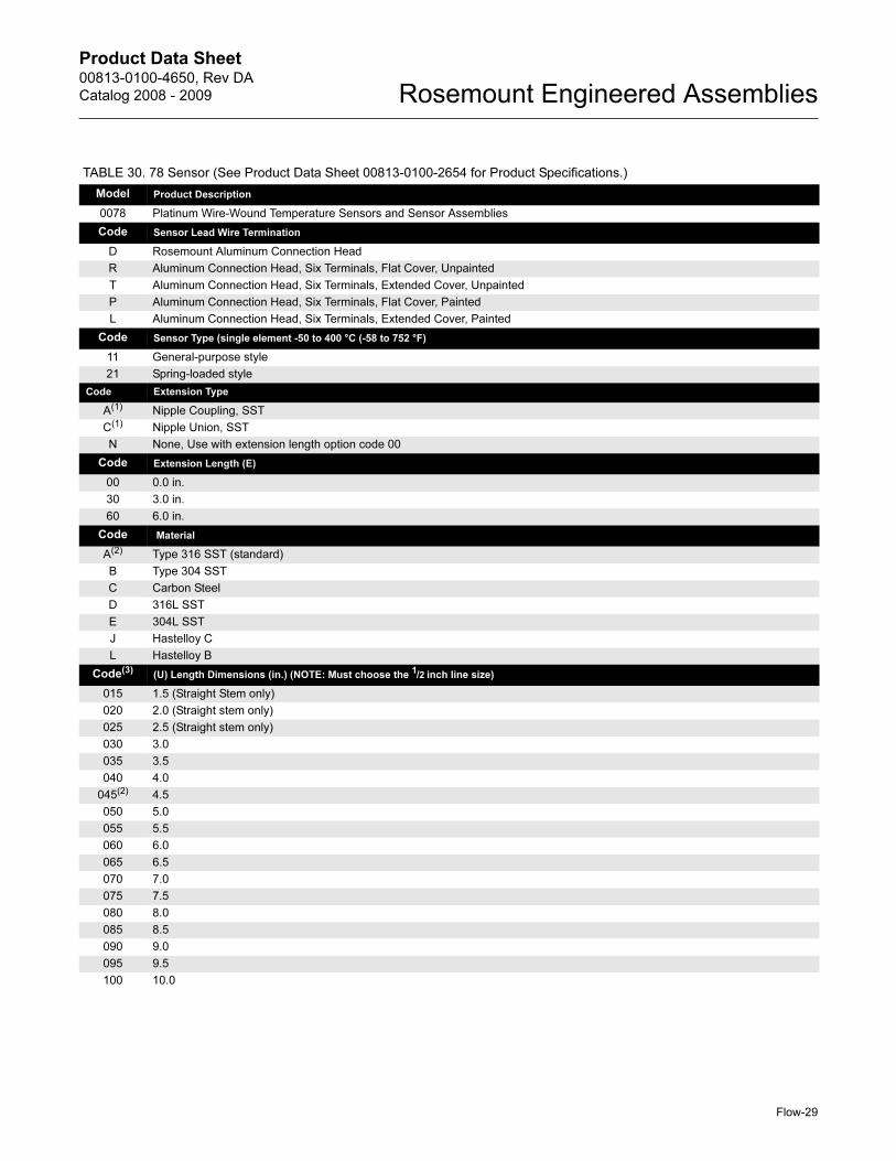
TABLE 30. 78 Sensor (See Product Data Sheet 00813-0100-2654 for Product Specifications.)
Model Product Description
0078 Platinum Wire-Wound Temperature Sensors and Sensor Assemblies
Code Sensor Lead Wire Termination
D Rosemount Aluminum Connection Head
R Aluminum Connection Head, Six Terminals, Flat Cover, Unpainted
T Aluminum Connection Head, Six Terminals, Extended Cover, Unpainted
P Aluminum Connection Head, Six Terminals, Flat Cover, Painted
L Aluminum Connection Head, Six Terminals, Extended Cover, Painted
Code Sensor Type (single element -50 to 400 °C (-58 to 752 °F)
11 General-purpose style
21 Spring-loaded style
Code Extension Type
A(1) Nipple Coupling, SST
C(1) Nipple Union, SST
N None, Use with extension length option code 00
Code Extension Length (E)
00 0.0 in.
30 3.0 in.
60 6.0 in.
Code Material
A(2) Type 316 SST (standard)
B Type 304 SST
C Carbon Steel
D 316L SST
E 304L SST
J Hastelloy C
L Hastelloy B
Code(3) (U) Length Dimensions (in.) (NOTE: Must choose the 1/2 inch line size)
015 1.5 (Straight Stem only)
020 2.0 (Straight stem only)
025 2.5 (Straight stem only)
030 3.0
035 3.5
040 4.0
045(2) 4.5
050 5.0
055 5.5
060 6.0
065 6.5
070 7.0
075 7.5
080 8.0
085 8.5
090 9.0
095 9.5
100 10.0
Product Data Sheet00813-0100-4650, Rev DA
Catalog 2008 - 2009Rosemount Engineered Assemblies
Flow-30
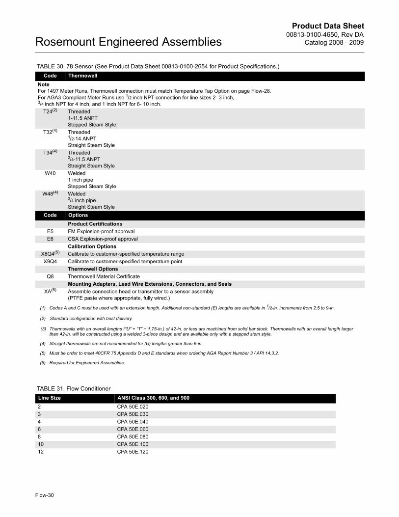
Code Thermowell
Note
For 1497 Meter Runs, Thermowell connection must match Temperature Tap Option on page Flow-28.
For AGA3 Compliant Meter Runs use 1/2 inch NPT connection for line sizes 2- 3 inch,3/4 inch NPT for 4 inch, and 1 inch NPT for 6- 10 inch.
T24(2) Threaded
1-11.5 ANPT
Stepped Steam Style
T32(4) Threaded1/2-14 ANPT
Straight Steam Style
T34(4) Threaded3/4-11.5 ANPT
Straight Steam Style
W40 Welded
1 inch pipe
Stepped Steam Style
W48(4) Welded3/4 inch pipe
Straight Steam Style
Code Options
Product Certifications
E5 FM Explosion-proof approval
E6 CSA Explosion-proof approval
Calibration Options
X8Q4(5) Calibrate to customer-specified temperature range
X9Q4 Calibrate to customer-specified temperature point
Thermowell Options
Q8 Thermowell Material Certificate
Mounting Adapters, Lead Wire Extensions, Connectors, and Seals
XA(6) Assemble connection head or transmitter to a sensor assembly
(PTFE paste where appropriate, fully wired.)
(1) Codes A and C must be used with an extension length. Additional non-standard (E) lengths are available in 1/2-in. increments from 2.5 to 9-in.
(2) Standard configuration with best delivery.
(3) Thermowells with an overall lengths (“U” + “T” + 1.75-in.) of 42-in. or less are machined from solid bar stock. Thermowells with an overall length largerthan 42-in. will be constructed using a welded 3-piece design and are available only with a stepped stem style.
(4) Straight thermowells are not recommended for (U) lengths greater than 6-in.
(5) Must be order to meet 40CFR 75 Appendix D and E standards when ordering AGA Report Number 3 / API 14.3.2.
(6) Required for Engineered Assemblies.
TABLE 31. Flow Conditioner
Line Size ANSI Class 300, 600, and 900
2 CPA 50E.020
3 CPA 50E.030
4 CPA 50E.040
6 CPA 50E.060
8 CPA 50E.080
10 CPA 50E.100
12 CPA 50E.120
TABLE 30. 78 Sensor (See Product Data Sheet 00813-0100-2654 for Product Specifications.)

Product Data Sheet00813-0100-4650, Rev DA
Catalog 2008 - 2009 Rosemount Engineered Assemblies
Flow-31
Emerson Process Management
© 2008 Rosemount Inc. All rights reserved.
¢00813-0100-4650Y¤
Standard Terms and Conditions of Sale can be found at www.rosemount.com\terms_of_saleThe Emerson logo is a trade mark and service mark of Emerson Electric Co. Rosemount and the Rosemount logotype are registered trademarks of Rosemount Inc.PlantWeb is a registered trademark of one of the Emerson Process Management group of companies.Eurofast and Minifast are registered trademarks of Turck Inc.All other marks are the property of their respective owners.
Product Data Sheet00813-0100-4650, Rev DA
Catalog 2008 - 2009Rosemount Engineered Assemblies
Emerson Process Management Heath PlaceBognor RegisWest Sussex PO22 9SHEnglandT 44 (0) 1243 863121F 44 (0) 1243 867554
Emerson Process Management Asia Pacific Private Limited1 Pandan CrescentSingapore 128461T (65) 6777 8211F (65) 6777 [email protected]
Rosemount Inc.8200 Market BoulevardChanhassen, MN 55317 USAT (U.S.) 1-800-999-9307T (International) (952) 906-8888F (952) 949-7001
www.rosemount.com