Rosemount 9901 Chamber for Process Level Instrumentation Radar chamber Product Data... · Product...
16
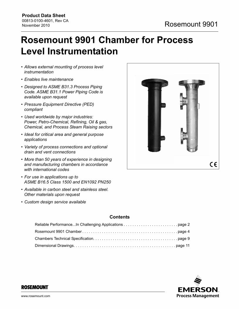
Product Data Sheet 00813-0100-4601, Rev CA November 2010 Rosemount 9901 www.rosemount.com • Allows external mounting of process level instrumentation • Enables live maintenance • Designed to ASME B31.3 Process Piping Code. ASME B31.1 Power Piping Code is available upon request • Pressure Equipment Directive (PED) compliant • Used worldwide by major industries: Power, Petro-Chemical, Refining, Oil & gas, Chemical, and Process Steam Raising sectors • Ideal for critical area and general purpose applications • Variety of process connections and optional drain and vent connections • More than 50 years of experience in designing and manufacturing chambers in accordance with international codes • For use in applications up to ASME B16.5 Class 1500 and EN1092 PN250 • Available in carbon steel and stainless steel. Other materials upon request • Custom design service available Contents Reliable Performance...In Challenging Applications . . . . . . . . . . . . . . . . . . . . . . . . . page 2 Rosemount 9901 Chamber . . . . . . . . . . . . . . . . . . . . . . . . . . . . . . . . . . . . . . . . . . . . page 4 Chambers Technical Specification. . . . . . . . . . . . . . . . . . . . . . . . . . . . . . . . . . . . . . . page 9 Dimensional Drawings. . . . . . . . . . . . . . . . . . . . . . . . . . . . . . . . . . . . . . . . . . . . . . . page 11 Rosemount 9901 Chamber for Process Level Instrumentation
Transcript of Rosemount 9901 Chamber for Process Level Instrumentation Radar chamber Product Data... · Product...
Product Data Sheet00813-0100-4601, Rev CANovember 2010 Rosemount 9901
www.rosemount.com
• Allows external mounting of process level instrumentation
• Enables live maintenance
• Designed to ASME B31.3 Process Piping Code. ASME B31.1 Power Piping Code is available upon request
• Pressure Equipment Directive (PED) compliant
• Used worldwide by major industries:Power, Petro-Chemical, Refining, Oil & gas, Chemical, and Process Steam Raising sectors
• Ideal for critical area and general purpose applications
• Variety of process connections and optional drain and vent connections
• More than 50 years of experience in designing and manufacturing chambers in accordance with international codes
• For use in applications up toASME B16.5 Class 1500 and EN1092 PN250
• Available in carbon steel and stainless steel. Other materials upon request
• Custom design service available
Contents
Reliable Performance...In Challenging Applications . . . . . . . . . . . . . . . . . . . . . . . . . page 2
Rosemount 9901 Chamber . . . . . . . . . . . . . . . . . . . . . . . . . . . . . . . . . . . . . . . . . . . . page 4
Chambers Technical Specification. . . . . . . . . . . . . . . . . . . . . . . . . . . . . . . . . . . . . . . page 9
Dimensional Drawings. . . . . . . . . . . . . . . . . . . . . . . . . . . . . . . . . . . . . . . . . . . . . . . page 11
Rosemount 9901 Chamber for Process Level Instrumentation
Product Data Sheet00813-0100-4601, Rev CA
November 2010Rosemount 9901
2
Reliable Performance...In Challenging Applications
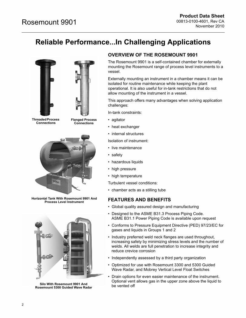
OVERVIEW OF THE ROSEMOUNT 9901The Rosemount 9901 is a self-contained chamber for externally mounting the Rosemount range of process level instruments to a vessel.
Externally mounting an instrument in a chamber means it can be isolated for routine maintenance while keeping the plant operational. It is also useful for in-tank restrictions that do not allow mounting of the instrument in a vessel.
This approach offers many advantages when solving application challenges:
In-tank constraints:
• agitator
• heat exchanger
• internal structures
Isolation of instrument:
• live maintenance
• safety
• hazardous liquids
• high pressure
• high temperature
Turbulent vessel conditions:
• chamber acts as a stilling tube
FEATURES AND BENEFITS• Global quality assured design and manufacturing
• Designed to the ASME B31.3 Process Piping Code.ASME B31.1 Power Piping Code is available upon request
• Conforms to Pressure Equipment Directive (PED) 97/23/EC for gases and liquids in Groups 1 and 2
• Industry preferred weld neck flanges are used throughout, increasing safety by minimizing stress levels and the number of welds. All welds are full penetration to increase integrity and reduce crevice corrosion
• Independently assessed by a third party organization
• Optimized for use with Rosemount 3300 and 5300 Guided Wave Radar, and Mobrey Vertical Level Float Switches
• Drain options for even easier maintenance of the instrument. Optional vent allows gas in the upper zone above the liquid to be vented off
Flanged Process Connections
Threaded Process Connections
Horizontal Tank With Rosemount 9901 AndProcess Level Instrument
Silo With Rosemount 9901 AndRosemount 5300 Guided Wave Radar
Product Data Sheet00813-0100-4601, Rev CANovember 2010
3
Rosemount 9901
CHAMBER DESIGN• Weld Neck Flanges And Full Penetration Welds are
in accordance with EN ISO 15614-1:2004, and ASME Boiler and Pressure Vessel Code Section IX
• All welders are qualified to EN 287-1:2004 and ASME Boiler and Pressure Vessel Code Section IX
• All construction materials have full traceability in accordance with the EN 10204 type 3.1 certificate
• Hydrostatic tests performed as standard
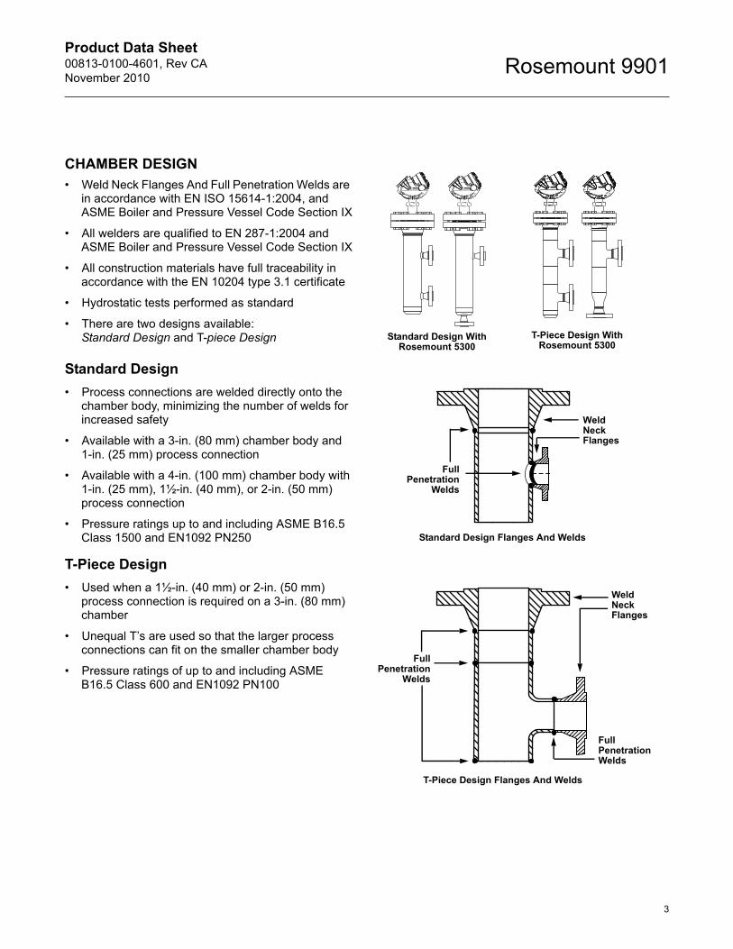
• There are two designs available: Standard Design and T-piece Design
Standard Design
• Process connections are welded directly onto the chamber body, minimizing the number of welds for increased safety
• Available with a 3-in. (80 mm) chamber body and 1-in. (25 mm) process connection
• Available with a 4-in. (100 mm) chamber body with1-in. (25 mm), 1½-in. (40 mm), or 2-in. (50 mm) process connection
• Pressure ratings up to and including ASME B16.5 Class 1500 and EN1092 PN250
T-Piece Design
• Used when a 1½-in. (40 mm) or 2-in. (50 mm) process connection is required on a 3-in. (80 mm) chamber
• Unequal T’s are used so that the larger process connections can fit on the smaller chamber body
• Pressure ratings of up to and including ASME B16.5 Class 600 and EN1092 PN100
WeldNeck Flanges
FullPenetration
Welds
WeldNeck Flanges
FullPenetration
Welds
FullPenetrationWelds
Standard Design Flanges And Welds
T-Piece Design Flanges And Welds
Standard Design With Rosemount 5300
T-Piece Design With Rosemount 5300
Product Data Sheet00813-0100-4601, Rev CA
November 2010Rosemount 9901
4
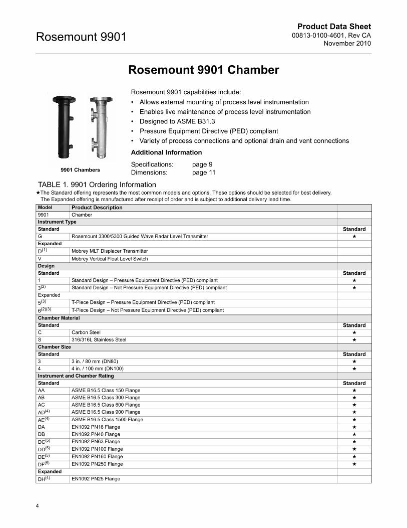
Rosemount 9901 Chamber
Rosemount 9901 capabilities include:
• Allows external mounting of process level instrumentation
• Enables live maintenance of process level instrumentation
• Designed to ASME B31.3
• Pressure Equipment Directive (PED) compliant
• Variety of process connections and optional drain and vent connections
Additional Information
Specifications: page 9Dimensions: page 11
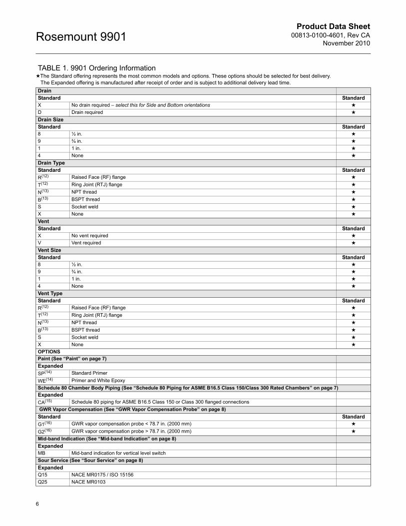
TABLE 1. 9901 Ordering Information★The Standard offering represents the most common models and options. These options should be selected for best delivery.
The Expanded offering is manufactured after receipt of order and is subject to additional delivery lead time.
Model Product Description9901 Chamber Instrument Type
Standard StandardG Rosemount 3300/5300 Guided Wave Radar Level Transmitter ★
Expanded
D(1) Mobrey MLT Displacer Transmitter
V Mobrey Vertical Float Level Switch
Design
Standard Standard1 Standard Design – Pressure Equipment Directive (PED) compliant ★
3(2) Standard Design – Not Pressure Equipment Directive (PED) compliant ★
Expanded
5(3) T-Piece Design – Pressure Equipment Directive (PED) compliant
6(2)(3) T-Piece Design – Not Pressure Equipment Directive (PED) compliant
Chamber Material
Standard StandardC Carbon Steel ★
S 316/316L Stainless Steel ★
Chamber Size
Standard Standard3 3 in. / 80 mm (DN80) ★
4 4 in. / 100 mm (DN100) ★
Instrument and Chamber Rating
Standard StandardAA ASME B16.5 Class 150 Flange ★
AB ASME B16.5 Class 300 Flange ★
AC ASME B16.5 Class 600 Flange ★
AD(4) ASME B16.5 Class 900 Flange ★
AE(4) ASME B16.5 Class 1500 Flange ★
DA EN1092 PN16 Flange ★
DB EN1092 PN40 Flange ★
DC(5) EN1092 PN63 Flange ★
DD(5) EN1092 PN100 Flange ★
DE(5) EN1092 PN160 Flange ★
DF(5) EN1092 PN250 Flange ★
Expanded
DH(4) EN1092 PN25 Flange
9901 Chambers

Product Data Sheet00813-0100-4601, Rev CANovember 2010
5
Rosemount 9901
Instrument Connection Type
Standard StandardR Raised Face (RF) flange ★
T Ring Joint (RTJ) flange ★
Expanded
N(6) NPT thread (1-in. Bottle Style Chamber)
Instrument Gasket
Standard Standard
1(7) Flat Ring (Sheet) ★
2(8) Spiral Wound (Stainless Steel 316 Inner Ring and Windings, Flexicarb Filler, Carbon Steel Outer Ring) ★
3(9) Ring Joint (ASME B16.5 Soft Iron or 316 Stainless Steel) ★
Expanded
4 None – select this for NPT thread (1-in. Bottle Style Chamber)
Process Connection Orientation
Standard StandardB Side and Side ★
C Side and Bottom ★
Process Connection Size
Standard Standard1 1 in. / 25 mm (DN25) ★
2(10) 2 in. / 50 mm (DN50) ★
5(10) 11/2 in. / 40 mm (DN40) ★
Process Connection RatingStandard StandardAA ASME B16.5 Class 150 Flange ★
AB ASME B16.5 Class 300 Flange ★
AC ASME B16.5 Class 600 Flange ★
AD ASME B16.5 Class 900 Flange ★
AE ASME B16.5 Class 1500 Flange ★
DA EN1092 PN16 Flange ★
DB EN1092 PN40 Flange ★
DC EN1092 PN63 Flange ★
DD EN1092 PN100 Flange ★
DE EN1092 PN160 Flange ★
DF EN1092 PN250 Flange ★
DH EN1092 PN25 Flange ★
NN For use with NPT, BSPT, or Socket Weld process connection type ★
Process Connection TypeStandard StandardR Raised Face (RF) flange ★
T Ring Type Joint (RTJ) flange ★
N(11) NPT thread ★
B(11) BSPT thread ★
S Socket weld ★
UnitsStandard StandardE Imperial (English), feet and inches ★
M Metric, meters and millimeters ★
Center-to-Center [feet or meters] (See dimension B on pages 11 and 14)Standard StandardXX Feet or Meters (e.g. 2 ft or 2 m is code 02) ★
Center-to-Center [inches or millimeters] (See dimension B on pages 11 and 14)Standard StandardXXX Inches (to 1/10 in.) or millimeters (e.g. 2 in. or 20 mm is code 020) ★
TABLE 1. 9901 Ordering Information★The Standard offering represents the most common models and options. These options should be selected for best delivery.
The Expanded offering is manufactured after receipt of order and is subject to additional delivery lead time.
Product Data Sheet00813-0100-4601, Rev CA
November 2010Rosemount 9901
6
DrainStandard StandardX No drain required – select this for Side and Bottom orientations ★
D Drain required ★
Drain SizeStandard Standard8 ½ in. ★
9 ¾ in. ★
1 1 in. ★
4 None ★
Drain TypeStandard Standard
R(12) Raised Face (RF) flange ★
T(12) Ring Joint (RTJ) flange ★
N(13) NPT thread ★
B(13) BSPT thread ★
S Socket weld ★
X None ★
VentStandard StandardX No vent required ★
V Vent required ★
Vent SizeStandard Standard8 ½ in. ★
9 ¾ in. ★
1 1 in. ★
4 None ★
Vent TypeStandard Standard
R(12) Raised Face (RF) flange ★
T(12) Ring Joint (RTJ) flange ★
N(13) NPT thread ★
B(13) BSPT thread ★
S Socket weld ★
X None ★
OPTIONSPaint (See “Paint” on page 7)
Expanded
SP(14) Standard Primer
WE(14) Primer and White Epoxy
Schedule 80 Chamber Body Piping (See “Schedule 80 Piping for ASME B16.5 Class 150/Class 300 Rated Chambers” on page 7)
Expanded
CA(15) Schedule 80 piping for ASME B16.5 Class 150 or Class 300 flanged connections
GWR Vapor Compensation (See “GWR Vapor Compensation Probe” on page 8)
Standard Standard
G1(16) GWR vapor compensation probe < 78.7 in. (2000 mm) ★
G2(16) GWR vapor compensation probe > 78.7 in. (2000 mm) ★
Mid-band Indication (See “Mid-band Indication” on page 8)
ExpandedMB Mid-band indication for vertical level switch
Sour Service (See “Sour Service” on page 8)
ExpandedQ15 NACE MR0175 / ISO 15156
Q25 NACE MR0103
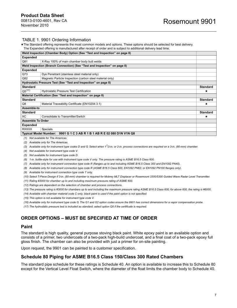
TABLE 1. 9901 Ordering Information★The Standard offering represents the most common models and options. These options should be selected for best delivery.
The Expanded offering is manufactured after receipt of order and is subject to additional delivery lead time.
Product Data Sheet00813-0100-4601, Rev CANovember 2010
7
Rosemount 9901
Weld Inspection (Chamber Body) Option (See “Test and Inspection” on page 8)
ExpandedQ81 X-Ray 100% of main chamber body butt welds
Weld Inspection (Branch Connection) (See “Test and Inspection” on page 8)
ExpandedQ73 Dye Penetrant (stainless steel material only)
Q82 Magnetic Particle Inspection (carbon steel material only)
Hydrostatic Pressure Test (See “Test and Inspection” on page 8)
Standard Standard
Q5(17) Hydrostatic Pressure Test Certification ★
Material Certification (See “Test and Inspection” on page 8)
Standard StandardQ8 Material Traceability Certificate (EN10204 3.1) ★
Assemble-to
Standard StandardXC Consolidate to Transmitter/Switch ★
Assemble To Order
ExpandedRXXXX Specials
Typical Model Number: 9901 G 1 C 3 AB R 1 B 1 AB R E 02 080 D1N V1N Q8
(1) Not available for The Americas.
(2) Available only for The Americas.
(3) Available only for instrument type codes D and G. Select when 11/2-in. or 2-in. process connections are required on a 3-in. (80-mm) chamber.
(4) Not available for instrument type code V.
(5) Not available for instrument type code D.
(6) 1-in. bottle-style for use with instrument type code V only. The pressure rating is ASME B16.5 Class 600.
(7) Available only for instrument connection type code R (flanges up to and including ASME B16.5 Class 300 and EN1092 PN40).
(8) Available only for instrument connection type code R (ASME B16.5 Class 600, EN1092 PN63, or EN1092 PN100 flanges only).
(9) Available for instrument connection type code T only.
(10) Select T-Piece Design if 3-in. (80-mm) chamber is required for Mobrey MLT Displacer or Rosemount 3300/5300 Guided Wave Radar Level Transmitter.
(11) Rating #3000 for chamber up to and including maximum pressure rating of ASME 600.
(12) Ratings are dependent on the selection of chamber and process connections.
(13) The pressure rating is #3000 for chambers up to and including the maximum pressure rating ASME B16.5 Class 600; for above 600, the rating is #6000.
(14) Available with chamber material code C only; black paint is used if the paint option is not specified.
(15) This option is not available for instrument type code V.
(16) Available only for instrument type code G. The G1 and G2 option codes ensure the 9901 has correct dimensions for a vapor compensation probe.
(17) The hydrostatic pressure test is included as standard; select option Q5 if the certificate is required.
ORDER OPTIONS – MUST BE SPECIFIED AT TIME OF ORDER
PaintThe standard is high quality, general purpose stoving black paint. White epoxy paint is an available option and consists of a primer, two undercoats of a two-pack high-build undercoat, and a final coat of a two-pack epoxy full gloss finish. The chamber can also be provided with just a primer for on-site painting.
Upon request, the 9901 can be painted to a customer specification.
Schedule 80 Piping for ASME B16.5 Class 150/Class 300 Rated Chambers
The standard pipe schedule for these ratings is Schedule 40. An option is available to increase this to Schedule 80 except for the Vertical Level Float Switch, where the diameter of the float limits the chamber body to Schedule 40.
TABLE 1. 9901 Ordering Information★The Standard offering represents the most common models and options. These options should be selected for best delivery.
The Expanded offering is manufactured after receipt of order and is subject to additional delivery lead time.
Product Data Sheet00813-0100-4601, Rev CA
November 2010Rosemount 9901
8
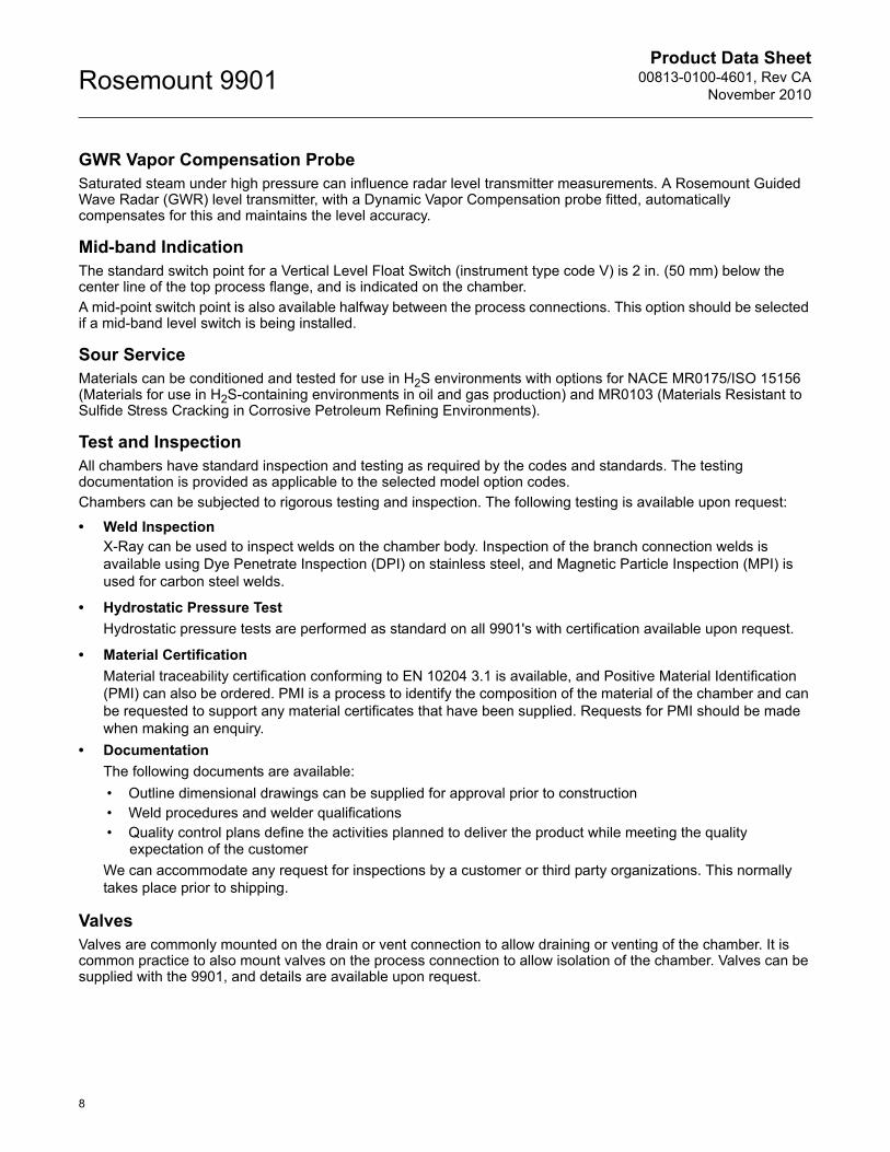
GWR Vapor Compensation ProbeSaturated steam under high pressure can influence radar level transmitter measurements. A Rosemount Guided Wave Radar (GWR) level transmitter, with a Dynamic Vapor Compensation probe fitted, automatically compensates for this and maintains the level accuracy.
Mid-band IndicationThe standard switch point for a Vertical Level Float Switch (instrument type code V) is 2 in. (50 mm) below the center line of the top process flange, and is indicated on the chamber.
A mid-point switch point is also available halfway between the process connections. This option should be selected if a mid-band level switch is being installed.
Sour ServiceMaterials can be conditioned and tested for use in H2S environments with options for NACE MR0175/ISO 15156 (Materials for use in H2S-containing environments in oil and gas production) and MR0103 (Materials Resistant to Sulfide Stress Cracking in Corrosive Petroleum Refining Environments).
Test and InspectionAll chambers have standard inspection and testing as required by the codes and standards. The testing documentation is provided as applicable to the selected model option codes.
Chambers can be subjected to rigorous testing and inspection. The following testing is available upon request:
• Weld InspectionX-Ray can be used to inspect welds on the chamber body. Inspection of the branch connection welds is available using Dye Penetrate Inspection (DPI) on stainless steel, and Magnetic Particle Inspection (MPI) is used for carbon steel welds.
• Hydrostatic Pressure Test
Hydrostatic pressure tests are performed as standard on all 9901's with certification available upon request.
• Material Certification
Material traceability certification conforming to EN 10204 3.1 is available, and Positive Material Identification (PMI) can also be ordered. PMI is a process to identify the composition of the material of the chamber and can be requested to support any material certificates that have been supplied. Requests for PMI should be made when making an enquiry.
• Documentation
The following documents are available:
• Outline dimensional drawings can be supplied for approval prior to construction• Weld procedures and welder qualifications• Quality control plans define the activities planned to deliver the product while meeting the quality
expectation of the customer
We can accommodate any request for inspections by a customer or third party organizations. This normally takes place prior to shipping.
ValvesValves are commonly mounted on the drain or vent connection to allow draining or venting of the chamber. It is common practice to also mount valves on the process connection to allow isolation of the chamber. Valves can be supplied with the 9901, and details are available upon request.
Product Data Sheet00813-0100-4601, Rev CANovember 2010
9
Rosemount 9901
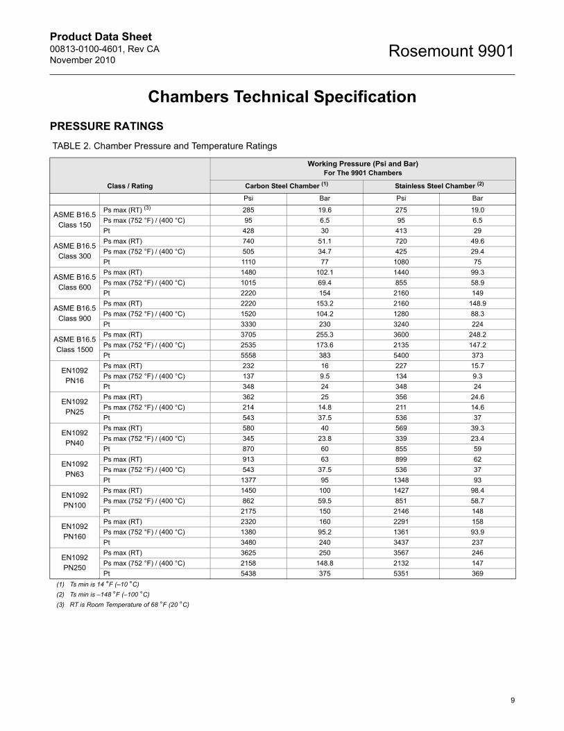
Chambers Technical Specification
PRESSURE RATINGS
TABLE 2. Chamber Pressure and Temperature Ratings
Class / Rating
Working Pressure (Psi and Bar)For The 9901 Chambers
Carbon Steel Chamber (1)
(1) Ts min is 14 °F (–10 °C)
Stainless Steel Chamber (2)
(2) Ts min is –148 °F (–100 °C)
Psi Bar Psi Bar
ASME B16.5 Class 150
Ps max (RT) (3)
(3) RT is Room Temperature of 68 °F (20 °C)
285 19.6 275 19.0
Ps max (752 °F) / (400 °C) 95 6.5 95 6.5
Pt 428 30 413 29
ASME B16.5 Class 300
Ps max (RT) 740 51.1 720 49.6
Ps max (752 °F) / (400 °C) 505 34.7 425 29.4
Pt 1110 77 1080 75
ASME B16.5 Class 600
Ps max (RT) 1480 102.1 1440 99.3
Ps max (752 °F) / (400 °C) 1015 69.4 855 58.9
Pt 2220 154 2160 149
ASME B16.5 Class 900
Ps max (RT) 2220 153.2 2160 148.9
Ps max (752 °F) / (400 °C) 1520 104.2 1280 88.3
Pt 3330 230 3240 224
ASME B16.5 Class 1500
Ps max (RT) 3705 255.3 3600 248.2
Ps max (752 °F) / (400 °C) 2535 173.6 2135 147.2
Pt 5558 383 5400 373
EN1092PN16
Ps max (RT) 232 16 227 15.7
Ps max (752 °F) / (400 °C) 137 9.5 134 9.3
Pt 348 24 348 24
EN1092PN25
Ps max (RT) 362 25 356 24.6
Ps max (752 °F) / (400 °C) 214 14.8 211 14.6
Pt 543 37.5 536 37
EN1092PN40
Ps max (RT) 580 40 569 39.3
Ps max (752 °F) / (400 °C) 345 23.8 339 23.4
Pt 870 60 855 59
EN1092PN63
Ps max (RT) 913 63 899 62
Ps max (752 °F) / (400 °C) 543 37.5 536 37
Pt 1377 95 1348 93
EN1092PN100
Ps max (RT) 1450 100 1427 98.4
Ps max (752 °F) / (400 °C) 862 59.5 851 58.7
Pt 2175 150 2146 148
EN1092PN160
Ps max (RT) 2320 160 2291 158
Ps max (752 °F) / (400 °C) 1380 95.2 1361 93.9
Pt 3480 240 3437 237
EN1092PN250
Ps max (RT) 3625 250 3567 246
Ps max (752 °F) / (400 °C) 2158 148.8 2132 147
Pt 5438 375 5351 369
Product Data Sheet00813-0100-4601, Rev CA
November 2010Rosemount 9901
10
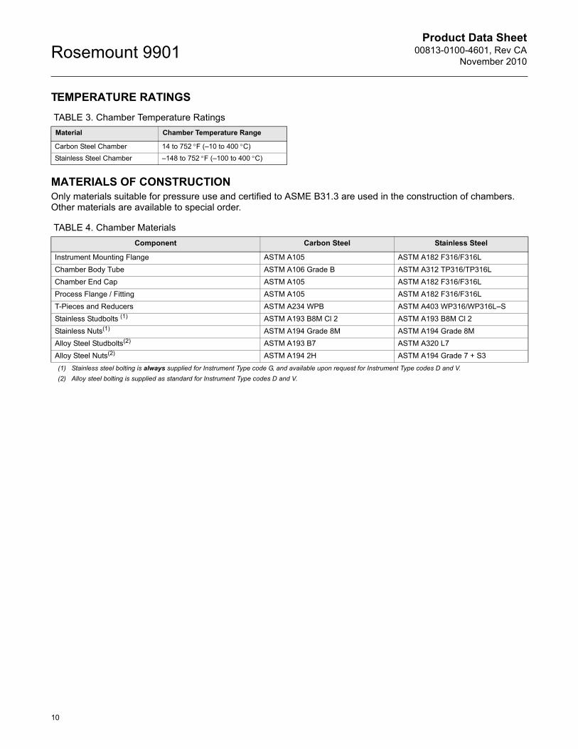
TEMPERATURE RATINGS
TABLE 3. Chamber Temperature Ratings
MATERIALS OF CONSTRUCTIONOnly materials suitable for pressure use and certified to ASME B31.3 are used in the construction of chambers. Other materials are available to special order.
TABLE 4. Chamber Materials
Material Chamber Temperature Range
Carbon Steel Chamber 14 to 752F (–10 to 400 C)
Stainless Steel Chamber –148 to 752F (–100 to 400 C)
Component Carbon Steel Stainless Steel
Instrument Mounting Flange ASTM A105 ASTM A182 F316/F316L
Chamber Body Tube ASTM A106 Grade B ASTM A312 TP316/TP316L
Chamber End Cap ASTM A105 ASTM A182 F316/F316L
Process Flange / Fitting ASTM A105 ASTM A182 F316/F316L
T-Pieces and Reducers ASTM A234 WPB ASTM A403 WP316/WP316L–S
Stainless Studbolts (1)
(1) Stainless steel bolting is always supplied for Instrument Type code G, and available upon request for Instrument Type codes D and V.
ASTM A193 B8M Cl 2 ASTM A193 B8M Cl 2
Stainless Nuts(1) ASTM A194 Grade 8M ASTM A194 Grade 8M
Alloy Steel Studbolts(2)
(2) Alloy steel bolting is supplied as standard for Instrument Type codes D and V.
ASTM A193 B7 ASTM A320 L7
Alloy Steel Nuts(2) ASTM A194 2H ASTM A194 Grade 7 + S3

Product Data Sheet00813-0100-4601, Rev CANovember 2010
11
Rosemount 9901
Dimensional Drawings
STANDARD DESIGN
Side-and-Side Chambers
Side-and-Bottom Chambers
Note:This chamber is available for Instrument Type Codes D, V, and G. See “9901 Ordering Information” on page 4 for an explanation of the codes.Dimensions A, C, D, and E are in the tables on pages 12 to 13. Specify center-to-center dimension B when ordering.
Optional Vent(Flanged, Threaded, or
Socket Weld)
Process Connection(Flanged, Threaded, or Socket Weld)
A
Drain(Flanged, Threaded, or
Socket Weld)
InstrumentConnection(Flanged)
InstrumentConnection(Threaded)
Optional Vent(Flanged,
Threaded, orSocket Weld)
Process Connection(Flanged, Threaded, or Socket Weld)
A
Drain(Flanged, Threaded, or
Socket Weld)D1
C2
B B
D2
C1
E
D1
C2
D2
C1
E
2 in.(50 mm)
2 in.(50 mm)
Note:This chamber design is available for Instrument Type Codes D, V, and G. See “9901 Ordering Information” on page 4 for an explanation of the codes.Dimensions A, D, and E are in the tables on pages 12 to 13. Specify center-to-center dimension B when ordering.
Process Connection(Flanged, Threaded, or
Socket Weld)
Process Connection(Flanged, Threaded, or Socket Weld)
Optional Vent(Flanged,
Threaded, orSocket Weld) A
InstrumentConnection(Flanged)
InstrumentConnection(Threaded)
Process Connection(Flanged, Threaded, or
Socket Weld)
Optional Vent(Flanged, Threaded, or
Socket Weld)
Process Connection(Flanged, Threaded, or Socket Weld)
B
A
B
D1
D2
E
D1
D2
E
2 in.(50 mm)
2 in.(50 mm)
Product Data Sheet00813-0100-4601, Rev CA
November 2010Rosemount 9901
12
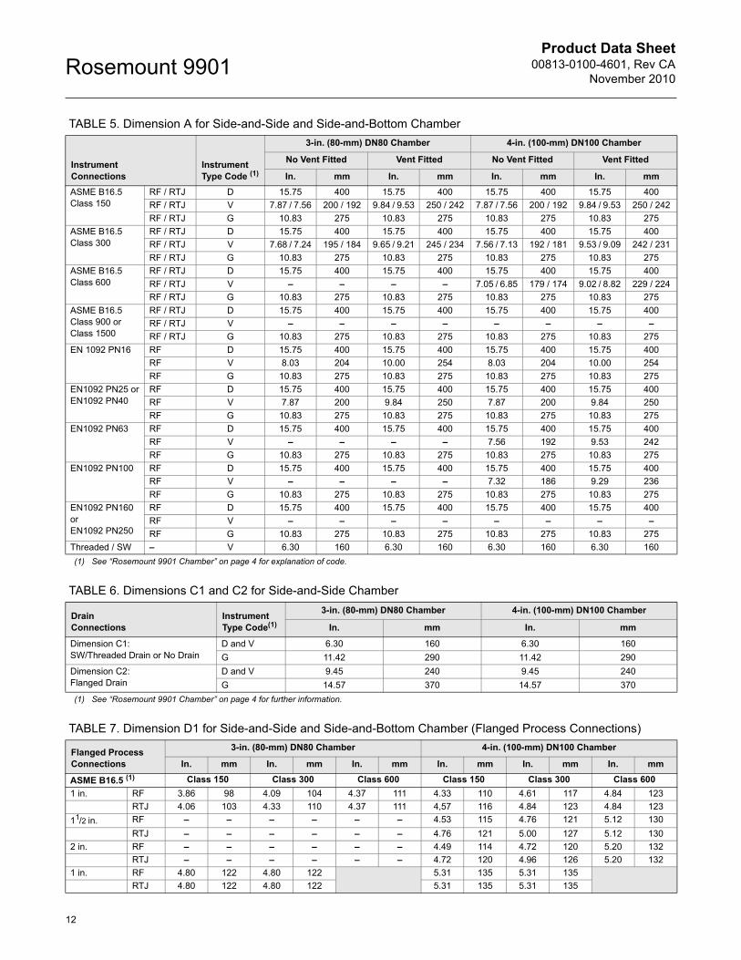
TABLE 5. Dimension A for Side-and-Side and Side-and-Bottom Chamber
TABLE 6. Dimensions C1 and C2 for Side-and-Side Chamber
TABLE 7. Dimension D1 for Side-and-Side and Side-and-Bottom Chamber (Flanged Process Connections)
InstrumentConnections
InstrumentType Code (1)
(1) See “Rosemount 9901 Chamber” on page 4 for explanation of code.
3-in. (80-mm) DN80 Chamber 4-in. (100-mm) DN100 Chamber
No Vent Fitted Vent Fitted No Vent Fitted Vent Fitted
In. mm In. mm In. mm In. mm
ASME B16.5 Class 150
RF / RTJ D 15.75 400 15.75 400 15.75 400 15.75 400
RF / RTJ V 7.87 / 7.56 200 / 192 9.84 / 9.53 250 / 242 7.87 / 7.56 200 / 192 9.84 / 9.53 250 / 242
RF / RTJ G 10.83 275 10.83 275 10.83 275 10.83 275
ASME B16.5 Class 300
RF / RTJ D 15.75 400 15.75 400 15.75 400 15.75 400
RF / RTJ V 7.68 / 7.24 195 / 184 9.65 / 9.21 245 / 234 7.56 / 7.13 192 / 181 9.53 / 9.09 242 / 231
RF / RTJ G 10.83 275 10.83 275 10.83 275 10.83 275
ASME B16.5 Class 600
RF / RTJ D 15.75 400 15.75 400 15.75 400 15.75 400
RF / RTJ V – – – – 7.05 / 6.85 179 / 174 9.02 / 8.82 229 / 224
RF / RTJ G 10.83 275 10.83 275 10.83 275 10.83 275
ASME B16.5 Class 900 or Class 1500
RF / RTJ D 15.75 400 15.75 400 15.75 400 15.75 400
RF / RTJ V – – – – – – – –
RF / RTJ G 10.83 275 10.83 275 10.83 275 10.83 275
EN 1092 PN16 RF D 15.75 400 15.75 400 15.75 400 15.75 400
RF V 8.03 204 10.00 254 8.03 204 10.00 254
RF G 10.83 275 10.83 275 10.83 275 10.83 275
EN1092 PN25 orEN1092 PN40
RF D 15.75 400 15.75 400 15.75 400 15.75 400
RF V 7.87 200 9.84 250 7.87 200 9.84 250
RF G 10.83 275 10.83 275 10.83 275 10.83 275
EN1092 PN63 RF D 15.75 400 15.75 400 15.75 400 15.75 400
RF V – – – – 7.56 192 9.53 242
RF G 10.83 275 10.83 275 10.83 275 10.83 275
EN1092 PN100 RF D 15.75 400 15.75 400 15.75 400 15.75 400
RF V – – – – 7.32 186 9.29 236
RF G 10.83 275 10.83 275 10.83 275 10.83 275
EN1092 PN160 orEN1092 PN250
RF D 15.75 400 15.75 400 15.75 400 15.75 400
RF V – – – – – – – –
RF G 10.83 275 10.83 275 10.83 275 10.83 275
Threaded / SW – V 6.30 160 6.30 160 6.30 160 6.30 160
DrainConnections
InstrumentType Code(1)
(1) See “Rosemount 9901 Chamber” on page 4 for further information.
3-in. (80-mm) DN80 Chamber 4-in. (100-mm) DN100 Chamber
In. mm In. mm
Dimension C1:SW/Threaded Drain or No Drain
D and V 6.30 160 6.30 160
G 11.42 290 11.42 290
Dimension C2:Flanged Drain
D and V 9.45 240 9.45 240
G 14.57 370 14.57 370
Flanged ProcessConnections
3-in. (80-mm) DN80 Chamber 4-in. (100-mm) DN100 Chamber
In. mm In. mm In. mm In. mm In. mm In. mm
ASME B16.5 (1) Class 150 Class 300 Class 600 Class 150 Class 300 Class 600
1 in. RF 3.86 98 4.09 104 4.37 111 4.33 110 4.61 117 4.84 123
RTJ 4.06 103 4.33 110 4.37 111 4,57 116 4.84 123 4.84 123
11/2 in. RF – – – – – – 4.53 115 4.76 121 5.12 130
RTJ – – – – – – 4.76 121 5.00 127 5.12 130
2 in. RF – – – – – – 4.49 114 4.72 120 5.20 132
RTJ – – – – – – 4.72 120 4.96 126 5.20 132
1 in. RF 4.80 122 4.80 122 5.31 135 5.31 135
RTJ 4.80 122 4.80 122 5.31 135 5.31 135
Product Data Sheet00813-0100-4601, Rev CANovember 2010
13
Rosemount 9901
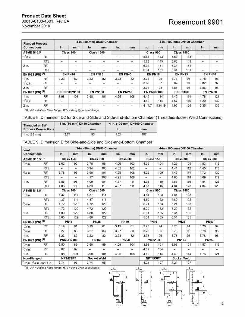
TABLE 8. Dimension D2 for Side-and-Side and Side-and-Bottom Chamber (Threaded/Socket Weld Connections)
TABLE 9. Dimension E for Side-and-Side and Side-and-Bottom Chamber
ASME B16.5 Class 900 Class 1500 Class 900 Class 1500
11/2 in. RF – – – – – – 5.63 143 5.63 143 – –
RTJ – – – – – – 5.63 143 5.63 143 – –
2 in. RF – – – – – – 6.34 161 6.34 161 – –
RTJ – – – – – – 6.34 161 6.34 161 – –
EN1092 (PN) (1) EN PN16 EN PN25 EN PN40 EN PN16 EN PN25 EN PN40
1 in. RF 3.23 82 3.23 82 3.23 82 3.78 96 3.78 96 3.78 96
11/2 in. RF – – – – – – 3.82 97 3.82 97 3.82 97
2 in. RF – – – – – – 3.74 95 3.86 98 3.86 98
EN1092 (PN) (1) EN PN63/PN100 EN PN160 EN PN250 EN PN63/100 EN PN160 EN PN250
1 in. RF 3.98 101 3.98 101 4.25 108 4.49 114 4.49 114 4.76 121
11/2 in. RF – – – – – – 4.49 114 4.57 116 5.20 132
2 in. RF – – – – – – 4.41/4.7 113/119 4.96 126 5.35 136
(1) RF = Raised Face flange. RTJ = Ring Type Joint flange.
Threaded or SW Process Connections
3-in. (80-mm) DN80 Chamber 4-in. (100-mm) DN100 Chamber
In. mm In. mm
1 in. (25 mm) 3.74 95 4.21 107
VentConnections
3-in. (80-mm) DN80 Chamber 4-in. (100-mm) DN100 Chamber
In. mm In. mm In. mm In. mm In. mm In. mm
ASME B16.5 (1)
(1) RF = Raised Face flange. RTJ = Ring Type Joint flange.
Class 150 Class 300 Class 600 Class 150 Class 300 Class 6001/2 in. RF 3.62 92 3.78 96 4.06 103 4.09 104 4.29 109 4.53 115
RTJ – – 3.94 100 4.02 102 – – 4.41 112 4.45 1133/4 in. RF 3.78 96 3.98 101 4.25 108 4.29 109 4.49 114 4.72 120
RTJ – – 4.17 106 4.25 108 – – 4.65 118 4.69 119
1 in. RF 3.86 98 4.09 104 4.37 111 4.33 110 4.57 116 4.84 123
RTJ 4.06 103 4.33 110 4.37 111 4.57 116 4.84 123 4.84 123
ASME B16.5 (1) Class 900 Class 1500 Class 900 Class 15001/2 in. RF 4.37 111 4.37 111 4.84 123 4.84 123
RTJ 4.37 111 4.37 111 4.80 122 4.80 1223/4 in. RF 4.72 120 4.72 120 5.24 133 5.24 133
RTJ 4.72 120 4.72 120 5.20 132 5.20 132
1 in. RF 4.80 122 4.80 122 5.31 135 5.31 135
RTJ 4.80 122 4.80 122 5.31 135 5.31 135
EN1092 (PN) (1) PN16 PN25 PN40 PN16 PN25 PN401/2 in. RF 3.19 81 3.19 81 3.19 81 3.70 94 3.70 94 3.70 943/4 in. RF 3.27 83 3.27 83 3.27 83 3.78 96 3.78 96 3.78 96
1 in. RF 3.23 82 3.23 82 3.23 82 3.78 96 3.78 96 3.78 96
EN1092 (PN) (1) PN63/PN100 PN160 PN250 PN63/100 PN160 PN2501/2 in. RF 3.50 89 3.50 89 4.09 104 3.98 101 3.98 101 4.57 1163/4 in. RF 3.62 92 – – – – 4.09 104 – – – –
1 in. RF 3.98 101 3.98 101 4.25 108 4.49 114 4.49 114 4.76 121
Non-Flanged NPT/BSPT Socket Weld NPT/BSPT Socket Weld1/2 in., 3/4 in, and 1 in. 3.74 95 3.74 95 4.21 107 4.21 107
Flanged ProcessConnections
3-in. (80-mm) DN80 Chamber 4-in. (100-mm) DN100 Chamber
In. mm In. mm In. mm In. mm In. mm In. mm
E E E E
A
B B
A A A
B B
D2
D1
D2
D1
D2
D1
D2
D1
C1C2
C1C2
Product Data Sheet00813-0100-4601, Rev CA
November 2010Rosemount 9901
14
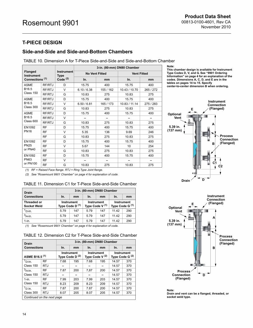
T-PIECE DESIGN
Side-and-Side and Side-and-Bottom Chambers
TABLE 10. Dimension A for T-Piece Side-and-Side and Side-and-Bottom Chamber
TABLE 11. Dimension C1 for T-Piece Side-and-Side Chamber
TABLE 12. Dimension C2 for T-Piece Side-and-Side Chamber
FlangedInstrumentConnections (1)
(1) RF = Raised Face flange. RTJ = Ring Type Joint flange.
InstrumentType Code (2)
(2) See “Rosemount 9901 Chamber” on page 4 for explanation of code.
3-in. (80-mm) DN80 Chamber
No Vent Fitted Vent Fitted
In. mm In. mm
ASMEB16.5Class 150
RF/RTJ D 15.75 400 15.75 400
RF/RTJ V 6.10 / 6.38 155 / 162 10.43 / 10.70 265 / 272
RF/RTJ G 10.83 275 10.83 275
ASMEB16.5Class 300
RF/RTJ D 15.75 400 15.75 400
RF/RTJ V 6.50 / 6.81 165 / 173 10.83 / 11.14 275 / 283
RF/RTJ G 10.83 275 10.83 275
ASMEB16.5Class 600
RF/RTJ D 15.75 400 15.75 400
RF/RTJ V – – – –
RF/RTJ G 10.83 275 10.83 275
EN1092 PN16
RF D 15.75 400 15.75 400
RF V 5.35 136 9.69 246
RF G 10.83 275 10.83 275
EN1092 PN25or PN40
RF D 15.75 400 15.75 400
RF V 5.67 144 10 254
RF G 10.83 275 10.83 275
EN1092 PN63or PN100
RF D 15.75 400 15.75 400
RF V – – – –
RF G 10.83 275 10.83 275
DrainConnections
3-in. (80-mm) DN80 Chamber
In. mm In. mm In. mm
Threaded orSocket Weld
InstrumentType Code D (1)
(1) See “Rosemount 9901 Chamber” on page 4 for explanation of code.
InstrumentType Code V (1)
InstrumentType Code G (1)
1/2-in. 5.79 147 5.79 147 11.42 2903/4-in. 5.79 147 5.79 147 11.42 290
1-in. 5.79 147 5.79 147 11.42 290
DrainConnections
3-in. (80-mm) DN80 Chamber
In. mm In. mm In. mm
ASME B16.5 (1)Instrument
Type Code D (2)Instrument
Type Code V (2)Instrument
Type Code G (2)
1/2-in. Class 150
RF 7.68 195 7.68 195 14.57 370
RTJ – – – – 14.57 3703/4-in.Class 150
RF 7.87 200 7,87 200 14.57 370
RTJ – – – – 14.57 370
1-in.Class 150
RF 7.99 203 7.99 203 14.57 370
RTJ 8.23 209 8.23 209 14.57 3701/2 in.Class 300
RF 7.87 200 7.87 200 14.57 370
RTJ 8.07 205 8.07 205 14.57 370
Continued on the next page
Note:Drain and vent can be a flanged, threaded, or socket weld type.
ProcessConnection
(Flanged)
OptionalVent
A
InstrumentConnection(Flanged)
OptionalVent
Drain
Process Connection(Flanged)
B
A
B
D
E
D
E
InstrumentConnection(Flanged)
Process Connection(Flanged)
C1C2
Note:This chamber design is available for Instrument Type Codes D, V, and G. See “9901 Ordering Information” on page 4 for an explanation of the codes. Dimensions A, C, D, and E are in the tables on pages 14 to 15. Specify center-to-center dimension B when ordering.
5.39 in.(137 mm)
5.39 in.(137 mm)

Product Data Sheet00813-0100-4601, Rev CANovember 2010
15
Rosemount 9901
TABLE 13. Dimension D for T-Piece Side-and-Side Chamber
TABLE 14. Dimension E for T-Piece Side-and-Side and Side-and-Bottom Chamber
ASME B16.5 (1)Instrument
Type Code D (2)Instrument
Type Code V (2)Instrument
Type Code G (2)
3/4 in.Class 300
RF 8.07 205 8.07 205 14.57 370
RTJ 8.31 211 8.31 211 14.57 370
1-in.Class 300
RF 8.23 209 8.23 209 14.57 370
RTJ 8.46 215 8.46 215 14.57 3701/2 in.Class 600
RF 8.11 206 8.11 206 14.57 370
RTJ 8.11 206 8.11 206 14.57 3703/4 in.Class 600
RF 8.31 211 8.31 211 14.57 370
RTJ 8.31 211 8.31 211 14.57 370
1 in.Class 600
RF 8.46 215 8.46 215 14.57 370
RTJ 8.46 215 8.46 215 14.57 370
EN1092 (PN) (1)
1/2-in. PN16/25/40 RF 7.28 185 7.28 185 14.57 3703/4-in. PN16/25/40 RF 7.36 187 7.36 187 14.57 370
1-in. PN16/25/40 RF 7.36 187 7.36 187 14.57 3701/2-in. PN63/100 RF 7.56 192 7.56 192 14.57 3703/4-in. PN63/100 RF 7.68 195 7.68 195 14.57 370
1-in. P63/100 RF 8.07 205 8.07 205 14.57 370
(1) RF = Raised Face flange. RTJ = Ring Type Joint flange.
(2) See “Rosemount 9901 Chamber” on page 4 for explanation of code.
Flanged ProcessConnections
3-in. (80-mm) DN80 Chamber
In. mm In. mm In. mm In. mm
ASME B16.5 (1)
(1) RF = Raised Face flange. RTJ = Ring Type Joint flange.
Class 150 Class 300 Class 600
11/2 in. RF 5,32 135 5.55 141 5.87 149
RTJ 5.47 139 5.79 147 5.87 149
2 in. RF 5.51 140 5.75 146 6.10 155
RTJ 5.67 144 5.98 152 6.18 157
EN 1092 (PN) (1) PN16 PN25/40 PN63 PN100
11/2 in. RF 4.65 118 4.65 118 5.32 135 5.32 135
2 in. RF 4.76 121 4.88 124 5.43 138 5.67 144
Vent Connections
3-in. (80-mm) DN80 Chamber
In. mm In. mm In. mm
ASME B16.5 (1)
(1) RF = Raised Face flange. RTJ = Ring Type Joint flange.
Class 150 Class 300 Class 6001/2 in. RF 3.62 92 3.78 96 4.06 103
RTJ – – 3.94 100 4.02 1023/4 in. RF 3.78 96 3.98 101 4.25 108
RTJ – – 4.17 106 4.25 108
1 in. RF 3.86 98 4.09 104 4.37 111
RTJ 4.06 103 4.33 110 4.37 111
EN1092 (PN) (1) PN16/25/40 PN63/1001/2 in. RF 3.20 81 3.50 893/4 in. RF 3.27 83 3.62 92
1 in. RF 3.23 82 3.98 101
Non-Flanged NPT/BSPT Socket Weld1/2 in. 3.74 95 3.74 953/4 in. 3.74 95 3.74 95
1 in. 3.74 95 3.74 95
DrainConnections
3-in. (80-mm) DN80 Chamber
In. mm In. mm In. mm
Table 12 continued from previous page
© 2010 Rosemount, Inc. All rights reserved.
Emerson Process Management Rosemount Measurement8200 Market BoulevardChanhassen, MN 55317 USATel (USA) 1 800 999 9307Tel (International) +1 952 906 8888Fax +1 952 949 7001www.rosemount.com
Emerson Process ManagementBlegistrasse 23P.O. Box 1046CH 6341 BaarSwitzerlandTel +41 (0) 41 768 6111Fax +41 (0) 41 768 6300
Emerson Process ManagementAsia Pacific Pte Ltd1 Pandan CrescentSingapore 128461Tel +65 6777 8211Fax +65 6777 0947Service Support Hotline: +65 6770 8711Email: [email protected]
Emerson FZEP.O. Box 17033Jebel Ali Free ZoneDubai UAETel +971 4 811 8100Fax +971 4 886 5465
Product Data Sheet00813-0100-4601, Rev CA
November 2010Rosemount 9901
00813-0100-4601 Rev CA 11/10
The Emerson logo is a trademark and service mark of Emerson Electric Co.Rosemount and the Rosemount logotype are registered trademarks of Rosemount Inc.PlantWeb is a registered trademark of one of the Emerson Process Management group of companies.HART is a registered trademark of the HART Communication Foundation.All other marks are the property of their respective owners.
Standard Terms and Conditions of Sale can be found at www.rosemount.com\terms_of_sale
Rosemount Level Solutions
Emerson provides a complete range of Rosemount products for level measurement applications.
Vibrating Fork Switches – Point Level Detection
For high and low alarms, overfill protection, pump control, including wide pressure and temperature requirements, and hygienic applications. Flexible mounting. Immune to changing process conditions and suitable for most liquids.The product line consists of:
• Rosemount 2160 Wireless
• Rosemount 2130 Enhanced
• Rosemount 2120 Full-featured
• Rosemount 2110 Compact
Differential Pressure – Level or Interface Measurement
Flexible mounting for liquid tank levels, including those with wide temperature and pressure requirements. Can be isolated by valves. Unaffected by: vapor space changes, surface conditions, foam, corrosive fluids, internal tank equipment. Optimize performance with direct mount, Tuned-System Assemblies:
• Rosemount DP Level Transmitters and Remote Seals
• Rosemount 3051S_L, 3051L, and 2051L Liquid Level Transmitters
Ultrasonic – Level Measurement
Top mounted, non-contacting for simple tank and open air level measurements. Unaffected by fluid properties such as: density, viscosity, dirty coating, and corrosiveness. Appropriate for routine applications outside of explosion proof areas.The product line consists of:
• Rosemount 3100 Series Ultrasonic Process Level Transmitters
Guided Wave Radar – Level and Interface Measurement
Top mounted, direct level and interface measurement of liquids or solids, including those with wide temperature and pressure requirements. Unaffected by changing process conditions. Good fit for small spaces and easy swap for older technologies.The product line consists of:
• Rosemount 5300 Series – Accurate, superior performance transmitter in most applications including process vessels and control
• Rosemount 3300 Series – Versatile and easy-to-use transmitter in most liquid storage and monitoring applications
Non-contacting Radar – Level Measurement
Top mounted, direct level measurement for liquids or solids, including those with wide temperature and pressure requirements. Can be isolated by valves. Unaffected by changing process conditions. Good for dirty, coating, and corrosive applications.The product line consists of:
• Rosemount 5400 Series – Accurate, superior performance 2-wire transmitters for most liquid level applications and process conditions
• Rosemount 5600 Series – 4-wire transmitters with maximum sensitivity and performance for solids, challenging reactors, rapid level changes, and excessive process conditions
Chambers for Process Level Instrumentation
• Rosemount 9901 – High quality chambers for external mounting of level measurement and control instrumentation on process vessels