rorris Development of new tools for crash and safety analysis
14
9. LS-DYNA Forum, Bamberg 2010 © 2010 Copyright by DYNAmore GmbH Development of New Tools for Crash and Safety Analysis. Performance driven LS-DYNA simulation with ANSA and META. Lambros Rorris , Yianni Kolokythas, Vasilios Pavlidis BETA CAE Systems SA, Thessaloniki, Greece Summary: The increasingly demanding and complex requirements in Crash Analysis, call for continuous and innovative software development. BETA CAE Systems in an effort to meet and exceed the requirements of the industry is introducing new technologies, both in the pre-processing area with ANSA, and in post-processing with μETA. This paper presents these new technologies. BETA CAE Systems goal has always been to provide fast and automated tools that allow the users to be efficient, and to easily manage their CAE models. Tools like the Batch Mesher, Data Management and Task Manager have provided solutions for the seamless workflow from CAD to Analysis. Recently, taking into account the needs and practices followed by most of the CAE users, a new tool has been introduced, designed for handling and controlling loadcase build-up with includes. This includes Configuration Manager in addition to simplifying the handling of includes configurations, it also keeps track of the different includes versions, with the assistance of the ANSA Data Manager, thus providing a unique advantage. In the field of Safety the rapid development work continuous. The need for better and more accurate behavior of Seatbelts has resulted in increased complexity of the Solver’s (LS-DYNA) seatbelt technologies. BETA has responded quickly to meet the new 2D Seatbelt requirements by advancing and automating the existing seatbelt tool. Increased automation has also been achieved in the areas of Seat-Dummy positioning, and Pedestrian and Interior Safety analysis set-up tools. In theses areas there is a need to provide the users with the ability to explore the validity of their models by performing Robustness and Sensitivity analysis. This area is currently heavily researched in order to provide easy to use tools for the engineers. New Functionality in the field of results transferring across simulations is being introduced. The build- up of a full crash model can be enriched by the results of stamping analysis, allowing for the consideration of local thickness changes and local hardening. The various aspects of streamlining the mapping process and handling the stamp data are addressed. Integral parts of the process are the transparent positioning of the parts from the stamp to the crash design space, the seamless application of the results and the model’s automatic update upon changes. Post-processing capabilities of META have also been complemented by significant developments. The support of FEMZIP files stemming from the latest FEMZIP version is added and the reading Crash II - Verbindungstechnik B - II - 39
Transcript of rorris Development of new tools for crash and safety analysis
9. LS-DYNA Forum, Bamberg 2010
© 2010 Copyright by DYNAmore GmbH
Development of New Tools for Crash and Safety Analysis. Performance driven LS-DYNA simulation
with ANSA and META.
Lambros Rorris, Yianni Kolokythas, Vasilios Pavlidis
BETA CAE Systems SA, Thessaloniki, Greece
Summary: The increasingly demanding and complex requirements in Crash Analysis, call for continuous and innovative software development. BETA CAE Systems in an effort to meet and exceed the requirements of the industry is introducing new technologies, both in the pre-processing area with ANSA, and in post-processing with µETA. This paper presents these new technologies. BETA CAE Systems goal has always been to provide fast and automated tools that allow the users to be efficient, and to easily manage their CAE models. Tools like the Batch Mesher, Data Management and Task Manager have provided solutions for the seamless workflow from CAD to Analysis. Recently, taking into account the needs and practices followed by most of the CAE users, a new tool has been introduced, designed for handling and controlling loadcase build-up with includes. This includes Configuration Manager in addition to simplifying the handling of includes configurations, it also keeps track of the different includes versions, with the assistance of the ANSA Data Manager, thus providing a unique advantage. In the field of Safety the rapid development work continuous. The need for better and more accurate behavior of Seatbelts has resulted in increased complexity of the Solver’s (LS-DYNA) seatbelt technologies. BETA has responded quickly to meet the new 2D Seatbelt requirements by advancing and automating the existing seatbelt tool. Increased automation has also been achieved in the areas of Seat-Dummy positioning, and Pedestrian and Interior Safety analysis set-up tools. In theses areas there is a need to provide the users with the ability to explore the validity of their models by performing Robustness and Sensitivity analysis. This area is currently heavily researched in order to provide easy to use tools for the engineers. New Functionality in the field of results transferring across simulations is being introduced. The build-up of a full crash model can be enriched by the results of stamping analysis, allowing for the consideration of local thickness changes and local hardening. The various aspects of streamlining the mapping process and handling the stamp data are addressed. Integral parts of the process are the transparent positioning of the parts from the stamp to the crash design space, the seamless application of the results and the model’s automatic update upon changes. Post-processing capabilities of META have also been complemented by significant developments. The support of FEMZIP files stemming from the latest FEMZIP version is added and the reading
Crash II - Verbindungstechnik
B - II - 39
9. LS-DYNA Forum, Bamberg 2010
© 2010 Copyright by DYNAmore GmbH
performance has been improved. The model handling has gained more flexibility through allowing different model attributes per window display, which also results in minimum memory requirements since multiple windows layout can be achieved without loading the same model multiple times. Materials are now identified and treated as pids providing a better overview of the model and enabling a post-processing on materials basis. Measuring has been enriched with more options such as the distance between different states, the calculation of angles between a user defined vector and any of the global axes or planes and the calculation of roll-pitch-yaw angles. Similarly, the tracking of distances and angles has been added to the processing of real test videos. The implementation of mapping algorithms has enabled, among others, the comparison of results of models with different mesh. More crash criteria have been added for within the 2Dplot module and correlation of curves is now possible. Reporting in pptx format is further enhanced and an Excel spreadsheet editor has been developed. Automation capabilities are extended even more and a new tool for the automatic creation of a pedestrian report, based on a minimum input from the user, is included now within the standard package. Keywords: ANSA, µETA, results mapping, safety, pedestrian, FMVSS 201, 2D seatbelt, search engine
Crash II - Verbindungstechnik
B - II - 40

9. LS-DYNA Forum, Bamberg 2010
© 2010 Copyright by DYNAmore GmbH
1 Introduction Recent developments in ANSA and µETA have introduced new powerful tools that allow the easy manipulation and management of LS-DYNA FE models. This powerful core functionality together with new modern User Interface design creates a powerful and intuitive working environment. This paper introduces some of these new technologies that have been introduced by BETA CAE Systems SA.
2 Safety
2.1 Seatbelt
A new re-designed seatbelt was recently introduced. Some of the characteristic features of the tool are: - Although the option to create both 1D and 2D seatbelts existed for years the new tool can also
route 2D seatbelts through sliprings taking advantage of the newly introduced LS-DYNA keywords. - The full support of LS-DYNA 2D *ELEMENT_SEATBELT keyword and the automatic creation of
needed deck set-up with the appropriate SETS, material and property cards. - Ability to interactively edit the path of the seatbelt to improve belt quality end meet the user’s liking.
The seatbelt slides on the dummy’s surface in real time following the mouse movements. - Seatbelts are ANSA entities. The information that is needed to create a seatbelt is stored and it’s
re-application is seamless. - Ability to automatically create all the peripheral elements that complete the definition of a seatbelt
system such as sliprings, retractor, pretentioners, contacts between seatbelt and dummy etc. Thus the whole seatbelt system configuration can be saved, applied and re-applied for different positions or load cases.
- The seatbelt information is written out in the deck output files as ANSA Comments. When a deck file is read back into ANSA, all the necessary information is there for tool to easily edit the seatbelts using the seatbelt tool.
Figure 1. Real time interactive edit of the belt’s path
2.2 Dummy
The increased use of full FE dummy models in crash and safety simulations have triggered the development of advanced tools for easy handling and articulation of these models.
Crash II - Verbindungstechnik
B - II - 41

9. LS-DYNA Forum, Bamberg 2010
© 2010 Copyright by DYNAmore GmbH
All “hierarchy tree” formats are supported including the old .tree LSTC format, PRIMER “*DUMMY_” keywords used by FTSS dummies as well as the new “occinfo” keywords used by newer LSTC dummies. The dummy positioning tools in ANSA allow for translation and rotation of a dummy and rotation of its parts. These tools have been updated to allow even more complex movements. The movements can either by driven from a window interface or interactively from the screen by just clicking and dragging. Limbs can be moved not only as rigid bodies performing a single rotation, but can also perform multiple limb movements, at once, as the user defines interactively the final position of any point of the limb. The final position of the dummy can be outputted with *NODE_TRANSFORM keywords in order to be able to keep intact the original validated dummy model.
2.3 Pedestrian
In version 13.x new functionality has been introduced that automatically applies the regulation directives to identify the target areas and target points. The latest EuroNCAP pedestrian testing protocol, the EU Phase 1 and Phase 2 (also known as GTR), JNCAP, TRIAS63 as well as the latest Grids Proposal of 2010 have been implemented in the Pedestrian Tool. Test procedures with headform and legform impactors can be set up. Bumper and bonnet reference lines are automatically calculated on the FE-model, or on Geometry data, closely following the regulation procedure. The ability to operate on Geometry data is especially useful for evaluation of the design in the concept phase. The Adult and Child Head form zones are defined and divided into the twelve areas. Moreover, user created curves can overwrite the curves that represent the reference lines. Thus the user can intervene in the process if it is needed. The users are also given the ability to apply single and multi positioning to the identified critical positions producing output files ready to be solved.
3 Results Mapping When aiming towards more realistic simulations, one analysis needs to use the results of a previous simulation as initial conditions. Such cases include transfer of physical data like nodal thicknesses, stresses and strains, material properties, and loads like pressures and temperatures. The “Results Mapping” functionality, offers a seamless way of integrating the transfer of results among standardized analysis types. The available functionality covers a wide range of applications, from mapping of Stamping Results to a Crash Analysis, to mapping of Pressure/Temperature distributions on a structural model. Within the preprocessor, the engineer can setup the exchange process of results among different solvers. The mapping, by default, takes into account the difference in meshes between the source data and the target model. Also, it considers changes in material orientations, converts scalar and tensor results, while taking into account changes in integration rules, sections and element orientations. In the special case of mapping stamping results, the process can - almost always - automatically match and position parts that are designed in different coordinate systems. Also, it handles the mesh changes introduced by the adaptive re-meshing and addresses situations where mapping may locally fail. Most stamping and crash formats along with their results are supported. Once the mapping process has been setup once, the software takes care of reapplying the source results on demand, when a change occurs. This allows the build of an accurate model of standardized quality. The user with topological criteria can also validate the final result.
Crash II - Verbindungstechnik
B - II - 42

9. LS-DYNA Forum, Bamberg 2010
© 2010 Copyright by DYNAmore GmbH
Figure 2. On top the stamping results are shown. Below the stamping results is mapped on the part.
4 Kinematics and Morphing Coupling A tight integration between the kinematics and the morphing tools was introduced. Deformable parts connecting different parts of the kinematic model can be controlled and reshaped automatically by the morphing tool. Examples are stabilizing bars, springs, deformable ducts, stretchable fabric covers etc.
Figure 3. Suspension spring getting linearly compressed during the kinematic motion
5 Connections
5.1 Connection Templates
Connection Template Manager is a new tool for the creation of multiple connection realization scenarios. Its concept is based on the fact that weldings are realized with different settings, according to several parameters, i.e. spot weld diameter or the number of parts connected. The user is able to
Crash II - Verbindungstechnik
B - II - 43

9. LS-DYNA Forum, Bamberg 2010
© 2010 Copyright by DYNAmore GmbH
create several connection scenarios each of them containing connections with different settings. According to the user needs, the appropriate connection scenario with its settings can be run to apply the settings to the connections and then through connection manager the connections can be realized.
Figure 4. Template set-up. Different connection template for different spotweld diameters
5.2 Spider 2 Connetion Types
The Spider 2 connection technology of ANSA allows to create solid spotwelds connections with pasted nodes and Heat Affected Zones automatically.
Figure 5. Solid spotweld with pasted nodes and HAZ
6 Includes Manager The Include Files Configurator (Configurator) is a tool that has been made available within ANSA preprocessor for the assembly of ready-to-run solver input decks at include file level. Figure 6 shows the GUI of the Configurator, depicting also a typical example of a vehicle separated in include files. The model tree consists of several includes structured in such a way, that it represents the modular build up of the car, for example the body in white (BIW), doors, under-bodies etc. Each of them is part of the model tree with a certain version and study version. Version can be considered as the major CAE-Version of the include, while the study version is a more private level of versions during the optimization process. The different include configurations can be seen in a detailed view in the middle of the GUI, serving in this way an overview which allows comparisons between them. Massive output of the main input decks is available through this interface, without the necessity to load them into the ANSA Preprocessing environment first. Of course, since the Configurator is part of ANSA, any configuration or separate include can be imported, in order to take advantage of the preprocessing functionality and to apply modifications or just simply check the FE-model quality.
Crash II - Verbindungstechnik
B - II - 44

9. LS-DYNA Forum, Bamberg 2010
© 2010 Copyright by DYNAmore GmbH
Figure 6. Includes Configurator interface
7 Search Engine As part of the continuous effort to modernize the User Interface on ANSA, the Search Engine was introduced in the program. This Engine has similar functionality with what it is already familiar to the users from their daily interaction with the web. Thus ANSA’s search engine allows to easily search program functions and model data. The user does not need to know the exact name of a function, but rather use descriptive keywords. The tool adapts and learns from the usage, so that common functions can be accessed by typing only two or three characters. This results is a tool that is more tolerant than a command line, but at the sometime more powerful and faster. The goal is to assist the new user to easily explore the functionality of the software and his/her model, and the experienced user to be more efficient.
8 µETA Post Processing
8.1 Reading Performance
µETA v6.6.x exhibits further improved reading performance with respect to femzip-compressed results. Reading performance is also increased for other cases such as the reading of csv files in 2Dplot module.
8.2 Graphics Improvements
The new rendering algorithm which is already available for over a year now, it is enhanced even more and covers all display options including the contouring of nodal data. A speedup factor of 2 to 8 is expected depending on the graphics card of the machine. This speedup is even higher in contour plots and fringe plots.
8.3 Computational Speed
Crash II - Verbindungstechnik
B - II - 45

9. LS-DYNA Forum, Bamberg 2010
© 2010 Copyright by DYNAmore GmbH
The latest versions include optimization of the code for multi-core system. This reduces computation time for intensive operations like section forces calculation, reading geometry and results, evaluating user field functions, filtering results, etc.
8.4 Model handling & connections
µETA undergoes continuous improvements regarding model handling targeting to the effortless post-processing which, at the same time, provides more flexibility and allows for a more detailed digging into the results. Materials are now treated as properties and that means that focusing actions as well as result filtering and identification can be performed on material level. The capability of conducting post-processing on several workspaces, named pages, provides the means for a better organization of the work. Moreover, the same model can be displayed with different attributes and with different results in different windows simultaneously and that provides great flexibility while at the same time removes the need to load the model more than once. Along with these, it comes the efficient handling of connections provided that the model geometry has been output by ANSA. All defined connections are grouped automatically according to their type and property and their handling as well as the identification of the critical ones becomes an easy task. In general, model handling will be further elevated in version 6.7 with the introduction of an improved GUI that will also incorporate new options for entities selection and it will allow loading of multiple results for the same state. Added to these, include files will be recognized automatically as groups.
8.5 Comparison studies
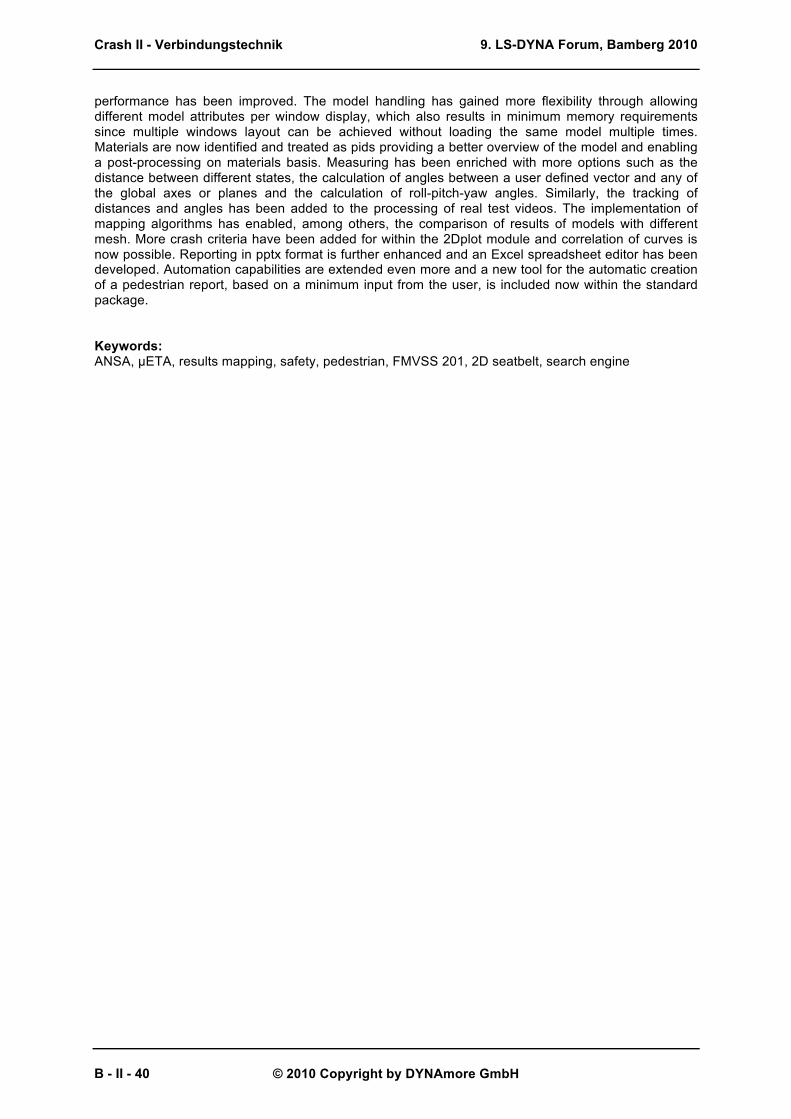
Comparison studies are tied together with post-processing but their conductance is constrained, in many cases, by certain bottlenecks such as performance and complexity. µETA exhibits an ongoing development, both in terms of performance and GUI, to facilitate the needs of comparison studies. Handling of multiple models is heavily assisted by the incomparable performance as well as by smart functionality such as the easy results loading, the flexible manipulation of multiple windows and the synchronization of focusing actions between models. Simultaneous listing and comparison of results deriving from different models is possible through statistics tables. Moreover, taking advantage of the newly introduced map algorithm, results differences can be calculated and displayed as contour plots both for deformation and scalar values even for models with non-compatible mesh. Version 6.7 will introduce an “overlay” functionality for 2D and 3D post processing. This will allow the post-processing conducted for 1 model to be reproduced automatically for multiple models.
Crash II - Verbindungstechnik
B - II - 46
9. LS-DYNA Forum, Bamberg 2010
© 2010 Copyright by DYNAmore GmbH
Figure 7. Geometry differences between 2 models
Figure 8. Stress differences between 2 models
8.6 Section Forces Calculation
The calculation of section forces is an important aspect throughout the design cycle of a structure. However, section forces must be predefined in the input deck, thus making unavoidable a second run in case it turns out that it is needed to investigate the force distribution in arbitrary areas of the structure. The section forces tool in µETA is capable to compute forces and moments at any section defined by the user or predefined in the input deck, achieving very good correlation with the solver calculated results.
Crash II - Verbindungstechnik
B - II - 47

9. LS-DYNA Forum, Bamberg 2010
© 2010 Copyright by DYNAmore GmbH
Figure 9. µETA calculated section forces compared to LS-DYNA
8.7 Report in Powerpoint pptx and spreadsheet editor
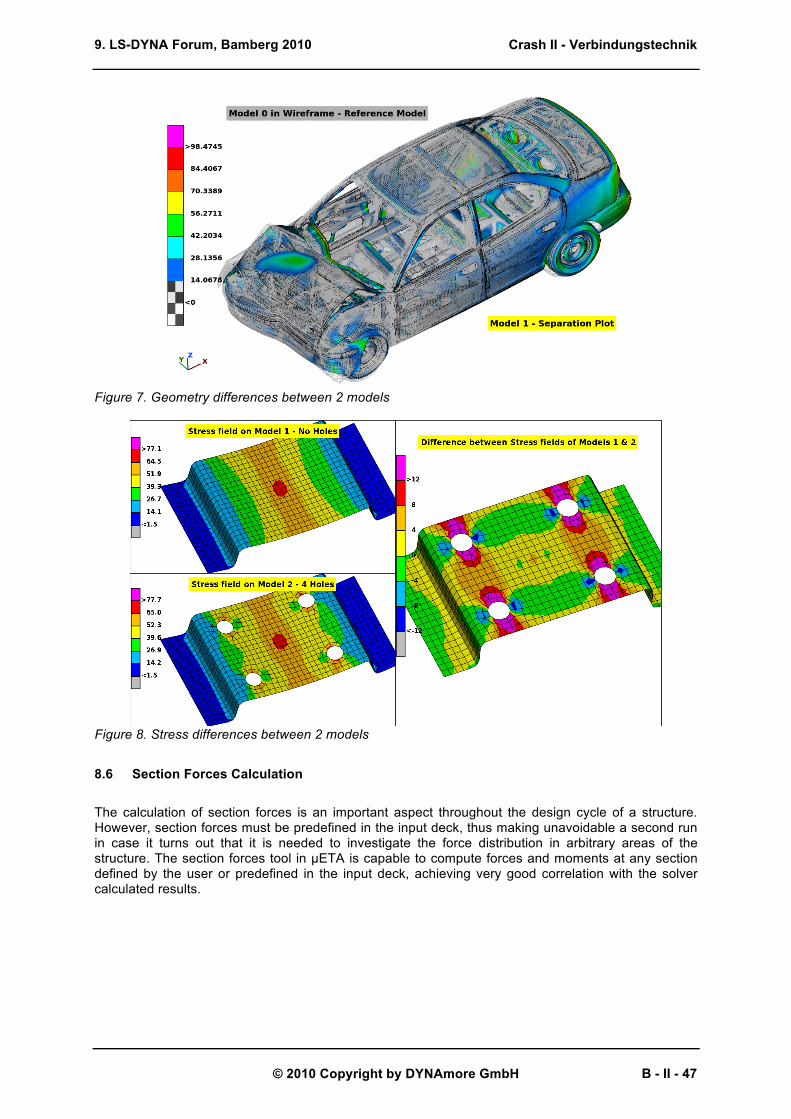
The new report composer tool allows the user to create a pptx report effortlessly, with powerpoint like functionality including Slide Master creation, Themes templates and drag & drop handling of objects. It is also possible to read and edit an existing pptx report, as well as to embed µETA viewer objects that include a 3d model or 2d plots that the user can interactively handle. Additionally the Copy/Paste functionality to Clipboard helps users to easily transfer images and data from µETA to other software. The set of reporting tools is now enriched with a spreadsheet editor featuring Excel-like functionality. This editor can be used either to input / modify spreadsheets within the report or to directly output its contents to xlsx format.
Figure 10. Spreadsheet editor
Crash II - Verbindungstechnik
B - II - 48
9. LS-DYNA Forum, Bamberg 2010
© 2010 Copyright by DYNAmore GmbH
Figure 11. µETA Report Composer
8.8 Ready-to-use tools for automated pedestrian report & optimizer coupling
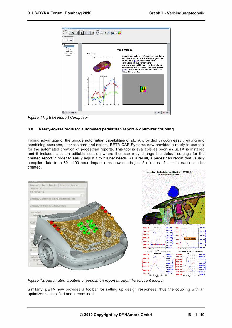
Taking advantage of the unique automation capabilities of µETA provided through easy creating and combining sessions, user toolbars and scripts, BETA CAE Systems now provides a ready-to-use tool for the automated creation of pedestrian reports. This tool is available as soon as µETA is installed and it includes also an editable session where the user may change the default settings for the created report in order to easily adjust it to his/her needs. As a result, a pedestrian report that usually compiles data from 80 - 100 head impact runs now needs just 5 minutes of user interaction to be created.
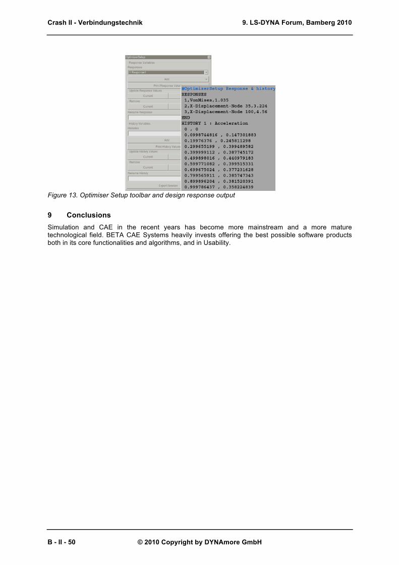
Figure 12. Automated creation of pedestrian report through the relevant toolbar Similarly, µETA now provides a toolbar for setting up design responses, thus the coupling with an optimizer is simplified and streamlined.
Crash II - Verbindungstechnik
B - II - 49
9. LS-DYNA Forum, Bamberg 2010
© 2010 Copyright by DYNAmore GmbH
Figure 13. Optimiser Setup toolbar and design response output
9 Conclusions Simulation and CAE in the recent years has become more mainstream and a more mature technological field. BETA CAE Systems heavily invests offering the best possible software products both in its core functionalities and algorithms, and in Usability.
Crash II - Verbindungstechnik
B - II - 50

9. LS-DYNA Forum, Bamberg 2010
© 2010 Copyright by DYNAmore GmbH
10 Literature [1] Halquist, J.O., LS-DYNA Keywords User’s manual. Version 971 R4, Livermore Software
Technology Corporation, Livermore, 2009 [2] ANSA version 13.0.1 User’s Guide, BETA CAE Systems S.A., July 2009 [3] µETA version 6.5.0 User’s Guide, BETA CAE Systems S.A., December 2009 [4] Siskos D., “Design and Organization of a post-Processing System for Structures’ Solution Data,
solved with the finite element method”, Doctorate Thesis, Aristotle University of Thessaloniki, Department of Mechanical Engineering, Greece, 2007.
Crash II - Verbindungstechnik
B - II - 51

9. LS-DYNA Forum, Bamberg 2010
© 2010 Copyright by DYNAmore GmbH
Crash II - Verbindungstechnik
B - II - 52
![Crash Course: Free vs. Paid Tools on LinkedIn [Webcast]](https://static.fdocuments.us/doc/165x107/58783b281a28ab707b8b533b/crash-course-free-vs-paid-tools-on-linkedin-webcast.jpg)


![45-Minute Crash Course: Free vs. Paid Tools on LinkedIn [Webcast]](https://static.fdocuments.us/doc/165x107/58e7ccc91a28ab0a228b6221/45-minute-crash-course-free-vs-paid-tools-on-linkedin-webcast.jpg)