Rope Direction
5
1 CHOOSING THE CORRECT LAY DIRECTION This document will discuss the selection of the proper rope lay direction for a conventional (grooved) drum hoist. The lay directi on of hoist rope will have an impact on the drum spooling. Furthermore, the correct lay direction can assist good spooling when a fleet angle is slightly out of spec. To accomplish this, we e xploit the n atural movement of a rope when loaded. It should be noted that the correct lay direction has greater significance for 6 stranded mine hoisting ropes and lesser for a spin resistant type. In general, the selection of a particular lay direction is used to overcome the effects on spooling when e ither too large or too small a fleet angle exists. It is the actual poin t at which the rope rises from one laye r to another that is c ritical. In this position , the rope must change direction and it is only the fleet angle and the lay direction that will assist (for this discussion, the use of a “kicker” is ignored as it has no impact of the theory). In order to select the correct rope lay direction, each installation must be studied on it’s own and the following items must be considered: - Fleet angles Hoisting layout / configuration & position of drum spout (side on which rope is attached to the drum) Hand Rule – determining the natural direction a rope will take Ha g g i e N o r t h A m e r i ca - Me e ti ng yo ur ho i sti ng nee d s! “ H H a a g g g g i i e e H H i i n n t t s s ” by George Delorme GEORGE DELORME Ph: 514-453-1283; Fax: 514-453-0631; Email: [email protected] ; Toll Free: 1-888-HAGGIE-9 424-4439) Iss ue 2 March 2001
-
Upload
mariappan-arumugam -
Category
Documents
-
view
212 -
download
0
description
Wire Rope lay
Transcript of Rope Direction
7/18/2019 Rope Direction
http://slidepdf.com/reader/full/rope-direction 1/5
1
CHOOSING THE CORRECT LAY DIRECTION
This document will discuss the selection of the proper rope lay direction for a
conventional (grooved) drum hoist.
The lay direction of hoist rope will have an impact on the drum spooling. Furthermore,
the correct lay direction can assist good spooling when a fleet angle is slightly out of
spec. To accomplish this, we exploit the natural movement of a rope when loaded. It
should be noted that the correct lay direction has greater significance for 6 stranded
mine hoisting ropes and lesser for a spin resistant type.
In general, the selection of a particular lay direction is used to overcome the effects
on spooling when either too large or too small a fleet angle exists. It is the actual point
at which the rope rises from one layer to another that is critical. In this position, the
rope must change direction and it is only the fleet angle and the lay direction that will
assist (for this discussion, the use of a “kicker” is ignored as it has no impact of the
theory).
In order to select the correct rope lay direction, each installation must be studied on
it’s own and the following items must be considered:-
Fleet angles
Hoisting layout / configuration & position of drum spout (side on which rope is
attached to the drum)
Hand Rule – determining the natural direction a rope will take
Haggie North America - Meeting your hoisting needs!
“ H H a a g g g g i i e e H H i i n n t t s s ” by George Delorme
GEORGE DELORME
Ph: 514-453-1283; Fax: 514-453-0631; Email: [email protected] ;
Toll Free: 1-888-HAGGIE-9 424-4439)
Issue 2 March 2001

7/18/2019 Rope Direction
http://slidepdf.com/reader/full/rope-direction 2/5
2
FLEET ANGLES:
By definition, the two fleet angles that exist on a single
drum are established as follows. An imaginary reference
line is drawn through the headsheave and perpendicular to
the drum. The two angles formed between this reference
line and the position of the rope at each drum flange are
the “fleet angles”.
The ideal fleet angle to assist good spooling is 120’.
As we move away from this value, the “rise point” (first
cross-over on each layer) will be negatively impacted and
we do recommend limits; the maximum being 1
45’ andthe minimum 0
30’.
It should also be mentioned that the fleet angles are formed by the geometry of the
hoisting layout i.e. compartment centers, drum width and position, distance from the
shaft to the drum etc., and cannot be changed by aligning the headsheave towards the
middle of the drum. The alignment of the sheave will only insure that the rope enters
the headsheave without hitting the flanges.
If the fleet angles are both close to 1
20’or
there is only one layer of rope on thedrum, then it does not matter which rope lay direction is used. Under these rare
circumstances, then a right hand lay is used for several reasons:-
1. Most rope-making machines are designed to fabricate right hand lay ropes and
are considered the standard.
2. If wire rope clips are used, they have corrugations to suit. (The corrugations
should be ground smooth if left lay ropes are used.)
Fleet an le #1
Fleet angle #2
7/18/2019 Rope Direction
http://slidepdf.com/reader/full/rope-direction 3/5
3
HOISTING LAYOUT:
In the process of selecting the correct lay direction, the hoisting layout must besketched as viewed from the hoistman’s position. The drum(s) is sketched positioned
on the page showing the side where the rope(s) is attached to the drum. The
headsheave(s) is sketched at the top of the page with all the fleet angles shown.
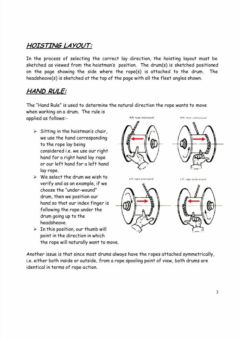
HAND RULE:
The “Hand Rule” is used to determine the natural direction the rope wants to move
when working on a drum. The rule is
applied as follows:-
Sitting in the hoistman’s chair,
we use the hand corresponding
to the rope lay being
considered i.e. we use our right
hand for a right hand lay rope
or our left hand for a left hand
lay rope.
We select the drum we wish toverify and as an example, if we
choose the “under-wound”
drum, then we position our
hand so that our index finger is
following the rope under the
drum going up to the
headsheave.
In this position, our thumb will
point in the direction in whichthe rope will naturally want to move.
Another issue is that since most drums always have the ropes attached symmetrically,
i.e. either both inside or outside, from a rope spooling point of view, both drums are
identical in terms of rope action.

7/18/2019 Rope Direction
http://slidepdf.com/reader/full/rope-direction 4/5
4
EXAMPLE:
In this scenario, we will look at one drum that has a very small fleet angle on the left
hand side and a very large fleet on the right hand side. The rope is coiled “over-wound”and is connected on the right hand flange. There are three layers of rope on the drum.
We will consider the effects of using a right hand lay rope. From the hand rule, we
know the rope will want to move naturally towards the left.
On the bottom layer, the rope moves away from the right hand flange, to which it is
attached, and the spooling is controlled by the drum grooves. When it arrives at the
left hand flange, it is forced up to the second layer and as it is balancing on the wrap
below, the force of the natural tendency of the right hand lay rope coupled with the
effects of the small fleet angle will cause the rope to be reluctant to leave the flange.
The wraps will tend to “build-up” as shown on the left side of the sketch. The result will
be a very hard and steep crossover leading to premature broken wires.
Rise pointfrom 1
st to
2nd
layer
Rise pointfrom 2
nd to
3rd
layer
Smallfleet
angle
Large
fleetangle
Note: The black arrows indicate the
force direction the fleet angle tends to
apply & the red is the natural rope movement
7/18/2019 Rope Direction
http://slidepdf.com/reader/full/rope-direction 5/5
5
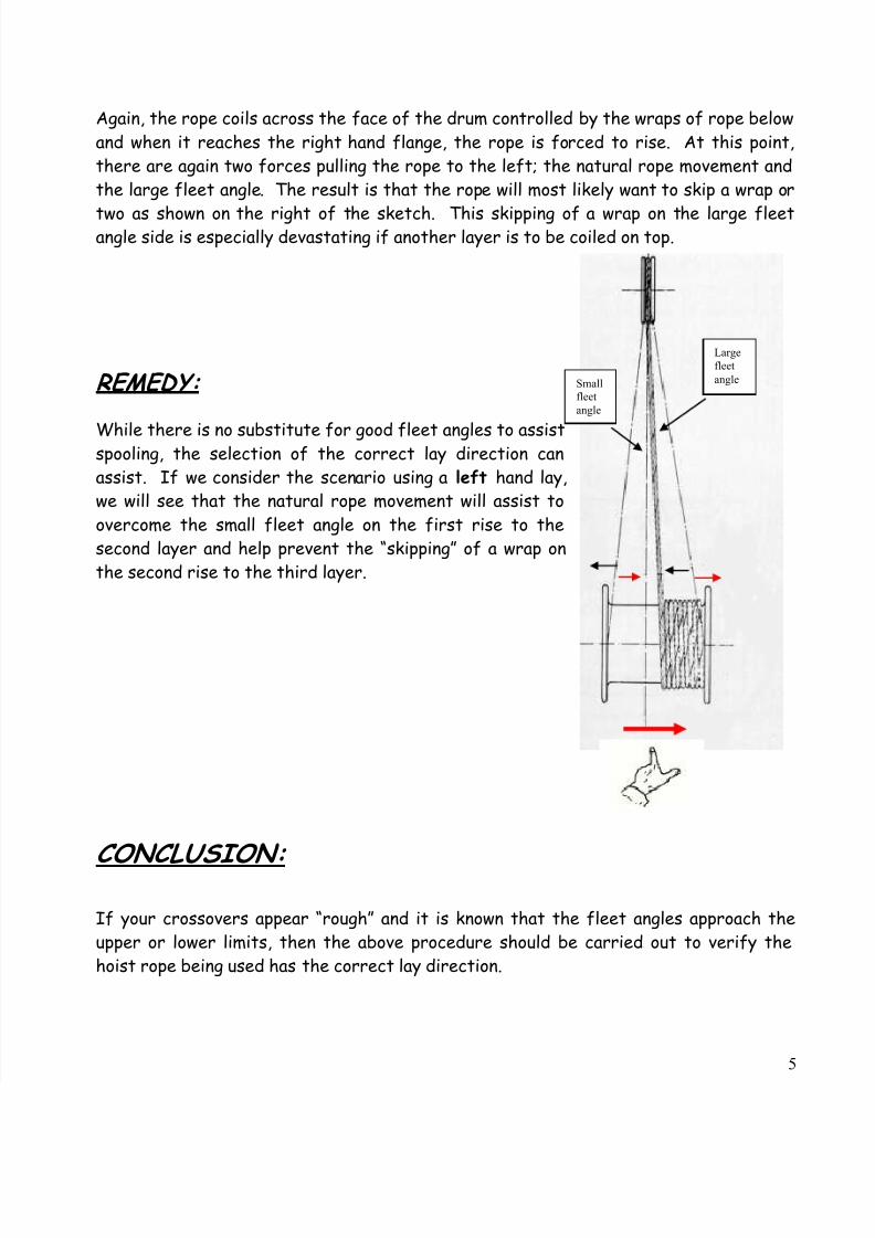
Again, the rope coils across the face of the drum controlled by the wraps of rope below
and when it reaches the right hand flange, the rope is forced to rise. At this point,
there are again two forces pulling the rope to the left; the natural rope movement and
the large fleet angle. The result is that the rope will most likely want to skip a wrap or
two as shown on the right of the sketch. This skipping of a wrap on the large fleetangle side is especially devastating if another layer is to be coiled on top.
REMEDY:
While there is no substitute for good fleet angles to assistspooling, the selection of the correct lay direction can
assist. If we consider the scenario using a left hand lay,
we will see that the natural rope movement will assist to
overcome the small fleet angle on the first rise to the
second layer and help prevent the “skipping” of a wrap on
the second rise to the third layer.
CONCLUSION:
If your crossovers appear “rough” and it is known that the fleet angles approach the
upper or lower limits, then the above procedure should be carried out to verify the
hoist rope being used has the correct lay direction.
Large
fleet
angleSmall
fleet
angle