
ROOT GRAPPLE LOADER ATTACHMENTS - John...
36
OWNER’S/OPERATOR’S MANUAL ROOT GRAPPLE LOADER ATTACHMENTS AV20 5WS105006 5/2008
Transcript of ROOT GRAPPLE LOADER ATTACHMENTS - John...

O W N E R ’ S / O P E R A T O R ’ S M A N U A L
ROOT GRAPPLELOADER
ATTACHMENTSAV20
5WS105006 5/2008
PART NO.
5WS105006

ii Introduction
TO THE DEALER:
Assembly and proper installation of this product is the responsibility of the Frontier dealer. Read manualinstructions and safety rules. Make sure all items on the Dealer’s Pre-Delivery and Delivery Check Lists in theOwner’s/Operator’s Manual are completed before releasing equipment to the owner.
The dealer must complete the Warranty Registration located on the Frontier website.
TO THE OWNER:
Read this manual before operating your Frontier equipment. The information presented will prepare you to do abetter and safer job. Keep this manual handy for ready reference. Require all operators to read this manual care-fully and become acquainted with all the adjustment and operating procedures before attempting to operate.Replacement manuals can be obtained from your Frontier dealer.
The equipment you have purchased has been carefully engineered and manufactured to provide dependable andsatisfactory use. Like all mechanical products, it will require cleaning and upkeep. Lubricate the unit as specified.Observe all safety information in this manual and safety decals on the equipment.
For service, your authorized Frontier dealer has trained mechanics, genuine Frontier service parts, and the neces-sary tools and equipment to handle all your needs.
Use only genuine Frontier service parts. Substitute parts will void the warranty and may not meet standardsrequired for safe and satisfactory operation. Record the model number and serial number of your equipment in thespaces provided:
Model:____________________________________ Date of Purchase:_________________
Serial Number: (see Safety Decal section for location)___________________________________
Provide this information to your dealer to obtain correct repair parts.
Throughout this manual, the term IMPORTANT is used to indicate that failure to observe can cause damage toequipment. The terms CAUTION, WARNING and DANGER are used in conjunction with the Safety-Alert Symbol,(a triangle with an exclamation mark), to indicate the degree of hazard for items of personal safety.
This Safety-Alert Symbol indicates a hazard and means ATTENTION!BECOME ALERT! YOUR SAFETY IS INVOLVED!
Indicates an imminently hazardous situation that, if not avoided, will result in death orserious injury.
Indicates a potentially hazardous situation that, if not avoided, could result in deathor serious injury, and includes hazards that are exposed when guards are removed.
Indicates a potentially hazardous situation that, if not avoided, may result in minor ormoderate injury.
Indicates that failure to observe can cause damage to equipment.
Indicates helpful information.
WARNING
CAUTION
IMPORTANTNOTE
DANGER
BOLT SIZE CHART
ABBREVIATIONS
Bolt Torque & Size Charts Appendix 33

BOLT TORQUE CHART
32 Appendix Bolt Torque & Size Charts Introduction 1
TABLE OF CONTENTSINTRODUCTION. . . . . . . . . . . . . . . . . . . . . . . . . . . . . . . . . . . . . . . . . . . . . . . ii - 1
SPECIFICATIONS . . . . . . . . . . . . . . . . . . . . . . . . . . . . . . . . . . . . . . . . . . . . . . . . 2
GENERAL INFORMATION . . . . . . . . . . . . . . . . . . . . . . . . . . . . . . . . . . . . . . . . . 2
SAFETY RULES. . . . . . . . . . . . . . . . . . . . . . . . . . . . . . . . . . . . . . . . . . . . . . . 3 - 5
SAFETY DECALS . . . . . . . . . . . . . . . . . . . . . . . . . . . . . . . . . . . . . . . . . . . . . 6 - 7
DEALER ASSEMBLY. . . . . . . . . . . . . . . . . . . . . . . . . . . . . . . . . . . . . . . . . . . . . . 8
DEALER CHECK LISTS . . . . . . . . . . . . . . . . . . . . . . . . . . . . . . . . . . . . . . . . . . . 9
INSTALLATION . . . . . . . . . . . . . . . . . . . . . . . . . . . . . . . . . . . . . . . . . . . . . . 10 - 15
OPERATION . . . . . . . . . . . . . . . . . . . . . . . . . . . . . . . . . . . . . . . . . . . . . . . . 16 - 18
OWNER SERVICE. . . . . . . . . . . . . . . . . . . . . . . . . . . . . . . . . . . . . . . . . . . . . . . 19
STORAGE . . . . . . . . . . . . . . . . . . . . . . . . . . . . . . . . . . . . . . . . . . . . . . . . . . . . . 19
TROUBLE-SHOOTING GUIDE . . . . . . . . . . . . . . . . . . . . . . . . . . . . . . . . . 20 - 21
PARTS LISTS . . . . . . . . . . . . . . . . . . . . . . . . . . . . . . . . . . . . . . . . . . . . . . . 22 - 29
PRODUCT WARRANTY . . . . . . . . . . . . . . . . . . . . . . . . . . . . . . . . . . . . . . . . . . 30
REPLACEMENT PARTS WARRANTY . . . . . . . . . . . . . . . . . . . . . . . . . . . . . . . 31
BOLT TORQUE CHART. . . . . . . . . . . . . . . . . . . . . . . . . . . . . . . . . . . . . . . . . . . 32
BOLT SIZE CHART & ABBREVIATIONS. . . . . . . . . . . . . . . . . . . . . . . . . . . . . . 33
Never let anyone operate this unit without reading the “Safety Precautions” and“Operations” sections of this manual.
Always choose hard, level ground to park the tractor and loader on and set the brakeso the unit cannot roll.
WARNING!
Replacement Parts Warranty 31
WARRANTYfor Parts
Worksaver Incorporated (“WORKSAVER”), warrants its’ parts to be free from defect in material andworkmanship for a period of ninety (90) days from the date of delivery of the part(s) to the originalpurchaser.
Replacement or repair parts installed in the equipment covered by warranty are warranted forninety (90) days from date of purchase of such part or to the expiration of the applicable newequipment warranty period, whichever occurs later.
Under no circumstances will this Warranty apply in the event that the product the parts are installedin, in the good faith opinion of WORKSAVER, has been subjected to improper operation, impropermaintenance, misuse, or an accident. This Warranty does not cover normal wear or tear, or normalmaintenance items.
This Warranty is extended solely to the original purchaser of the product. Should the original pur-chaser sell or otherwise transfer this product to a third party, this Warranty does not transfer to the thirdparty purchaser in any way. There are no third party beneficiaries of this Warranty.
WORKSAVERS’ obligation under this Warranty is limited to, at WORKSAVERS’ option, the repair orreplacement, free of charge, of the product if WORKSAVER, in its sole discretion, deems it to bedefective or in noncompliance with this Warranty. The selling dealer shall provide such parts to the userduring regular working hours. If requested, the product must be returned to WORKSAVER withproof of purchase within thirty (30) days after such defect or noncompliance is discovered orshould have been discovered, routed through the dealer and distributor from whom the purchasewas made, transportation charges prepaid. WORKSAVER shall complete such repair or replacementwithin a reasonable time after WORKSAVER receives the product.THERE ARE NO OTHER REMEDIESUNDER THIS WARRANTY. THE REMEDY OF REPAIR OR REPLACEMENT IS THE SOLE ANDEXCLUSIVE REMEDY UNDER THIS WARRANTY.
THERE ARE NO WARRANTIES WHICH EXTEND BEYOND THE DESCRIPTION ON THE FACEOF THIS WARRANTY. WORKSAVER MAKES NO OTHER WARRANTY, EXPRESS OR IMPLIED, ANDWORKSAVER SPECIFICALLY DISCLAIMS ANY IMPLIED WARRANTY OF MERCHANTABILITYAND/OR ANY IMPLIED WARRANTY OF FITNESS FOR A PARTICULAR PURPOSE.
WORKSAVER shall not be liable for any incidental or consequential losses, damages orexpenses, arising directly or indirectly from the product, whether such claim is based uponbreach of contract, breach of warranty, negligence, strict liability in tort or any other legaltheory. Without limiting the generality of the foregoing, Worksaver specifically disclaims any damagesrelating to (i) lost profits, business, revenues or goodwill; (ii) loss of crops; (iii) loss because of delay inharvesting; (iv) any expense or loss incurred for labor, supplies, substitute machinery or rental; or (v)any other type of damage to property or economic loss.
This Warranty is subject to any existing conditions of supply which may directly affect WORK-SAVERS’ ability to obtain materials or manufacture replacement parts.
No agent, representative, dealer, distributor, service person, salesperson, or employee of anycompany, including without limitation, WORKSAVER, its authorized dealers, distributors, and servicecenters, is authorized to alter, modify, or enlarge this Warranty.
For warranty services contact your selling dealer.
2 Introduction
GENERAL INFORMATION
The purpose of this manual is to assist you inoperating and maintaining your Root Grapple.Read it carefully. It furnishes information andinstructions that will help you achieve years ofdependable performance.
These instructions have been compiled fromfield experience and engineering data. Someinformation may be general in nature, due tounknown and varying operating conditions.However, through experience and these instruc-tions, you should be able to develop proceduressuitable to your particular situation.
The illustrations and data used in this manualwere current at the time of printing. However,due to possible inline production changes,your machine may vary slightly in detail. Wereserve the right to redesign and change themachines as may be necessary without noti-fication.
Throughout this manual, references are made toright and left direction. These are determined bystanding behind the tractor facing the direction offorward travel.
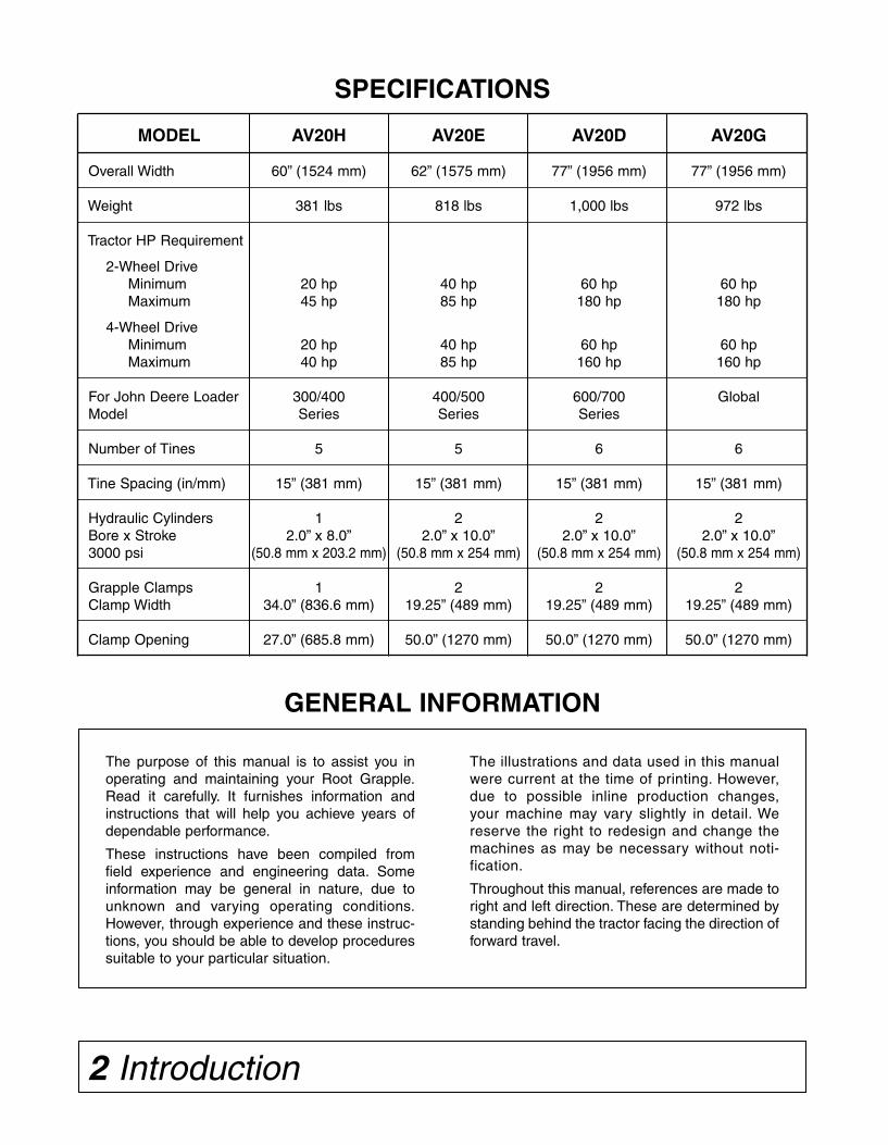
SPECIFICATIONS
MODEL AV20H AV20E AV20D AV20G
Overall Width 60” (1524 mm) 62” (1575 mm) 77” (1956 mm) 77” (1956 mm)
Weight 381 lbs 818 lbs 1,000 lbs 972 lbs
Tractor HP Requirement
2-Wheel DriveMinimum 20 hp 40 hp 60 hp 60 hpMaximum 45 hp 85 hp 180 hp 180 hp
4-Wheel DriveMinimum 20 hp 40 hp 60 hp 60 hpMaximum 40 hp 85 hp 160 hp 160 hp
For John Deere Loader 300/400 400/500 600/700 GlobalModel Series Series Series
Number of Tines 5 5 6 6
Tine Spacing (in/mm) 15” (381 mm) 15” (381 mm) 15” (381 mm) 15” (381 mm)
Hydraulic Cylinders 1 2 2 2Bore x Stroke 2.0” x 8.0” 2.0” x 10.0” 2.0” x 10.0” 2.0” x 10.0”3000 psi (50.8 mm x 203.2 mm) (50.8 mm x 254 mm) (50.8 mm x 254 mm) (50.8 mm x 254 mm)
Grapple Clamps 1 2 2 2Clamp Width 34.0” (836.6 mm) 19.25” (489 mm) 19.25” (489 mm) 19.25” (489 mm)
Clamp Opening 27.0” (685.8 mm) 50.0” (1270 mm) 50.0” (1270 mm) 50.0” (1270 mm)
Safety 3
SAFETY RULESATTENTION! BECOME ALERT! YOUR SAFETY IS INVOLVED!
Safety is a primary concern in the design andmanufacture of our products. Unfortunately, ourefforts to provide safe equipment can be wipedout by an operator’s single careless act.
In addition to the design and configuration ofequipment, hazard control and accident preven-tion are dependent upon the awareness,concern, judgement, and proper training ofpersonnel involved in the operation, transport,maintenance and storage of equipment.
It has been said “The best safety device is aninformed, careful operator.” We ask you to be thatkind of operator.
TRAINING■■ Safety instructions are important! Read allattachment and power unit manuals; follow allsafety rules and safety decal information.(Replacement manuals are available from sellingdealer.) Failure to follow instructions or safetyrules can result in serious injury or death.
■■ If you do not understand any part of this man-ual and need assistance, see your dealer.
■■ Operators must be instructed in and be capa-ble of the safe operation of the equipment, itsattachments, and all controls. Do not allow any-one to operate this equipment without properinstructions.
■■ Never allow children or untrained persons tooperate equipment.
■■ Train all new personnel and review instructionsfrequently with existing workers. A person who hasnot read and understood all operating and safetyinstructions is not qualified to operate themachine. An untrained operator exposes himselfand bystanders to possible serious injury or death.
PREPARATION■■ Always wear relatively tight and belted clothingto avoid getting caught in moving parts. Wear stur-dy, rough-soled work shoes and protective equip-ment for eyes, hair, hands, hearing, and head; andrespirator or filter mask where appropriate.
■■ Make sure attachment is properly secured,adjusted, and in good operating condition.
■■ Power unit must be equipped with ROPS orROPS cab and seat belt. Keep seat belt securelyfastened. Falling off power unit can result in deathfrom being run over or crushed. Keep foldableROPS system in “locked up” position at all times.
■■ A heavy load can cause instability in driving apower unit. Make sure the rear of the tractor isproperly counter-balanced with weights. Alwaysdrive slowly – especially around turns. An unsta-ble power unit could steer badly and possibly tipover, causing injury or death.The use of the optional rear 3 pt. ballast box isrecommended. Ask your dealer.
■■ Do not exceed the lift capacity of your loader.See loader specifications.
■■ Know your equipment's capabilities, dimen-sions, and operations before operating. Visuallyinspect your equipment before you start, andnever operate equipment that is not in properworking order with all safety devices intact.Check all hardware to ensure it is tight. Make cer-tain that all locking pins, latches, and connectiondevices are properly installed and secured.Remove and replace any damaged, fatigued, orexcessively worn parts. Make certain all safetydecals are in place and are legible. Keep decalsclean, and replace them if they become worn orhard to read.
■■ Move wheels to the widest recommended set-ting to increase stability.
■■ Do not work under raised loaders without sup-porting them. Do not use support material madeof concrete blocks, logs, buckets, barrels, or anyother material that could suddenly collapse orshift positions. Make sure support material issolid, not decayed, warped, twisted, or tapered.Lower loaders to ground level or on blocks.Lower loaders and attachments to the groundbefore leaving the cab or operator's station.
■■ Check the power unit's hydraulic system. Besure the hydraulic oil and filter have been serv-iced according to manufacturer's recommenda-tions. Refer to your power unit loader operator'smanual or dealer for any adjustments necessaryto put the hydraulic system in good workingorder.
WARRANTYPlease enter information below and save for future reference.Date Purchased:___________________________ From (Dealer): _____________________________Model Number:____________________________ Serial Number:_____________________________
Worksaver Incorporated (“WORKSAVER”), warrants this product to be free from defect in material and work-manship. Except as otherwise set forth below, the duration of this Warranty shall be for TWELVE (12) MONTHSCOMMENCING ON THE DATE OF DELIVERY OF THE PRODUCT TO THE ORIGINAL PURCHASER.
Under no circumstances will this Warranty apply in the event that the product, in the good faith opinion ofWORKSAVER, has been subjected to improper operation, improper maintenance, misuse, or an accident. ThisWarranty does not apply in the event that the product has been materially modified or repaired by someoneother than WORKSAVER, a WORKSAVER authorized dealer or distributor, and/or a WORKSAVER authorizedservice center. This Warranty does not cover normal wear or tear, or normal maintenance items. This Warrantyalso does not cover repairs made with parts other than those obtainable through WORKSAVER.
This Warranty is extended solely to the original purchaser of the product. Should the originalpurchaser sell or otherwise transfer this product to a third party, this Warranty does not transfer to thethird party purchaser in any way. There are no third party beneficiaries of this Warranty.
WORKSAVER makes no warranty, express or implied, with respect to cutting edges, shanks, tires orother parts or accessories not manufactured by WORKSAVER. Warranties for these items, if any, are pro-vided separately by their respective manufacturers.
WORKSAVERS’ obligation under this Warranty is limited to, at WORKSAVERS’ option, the repair orreplacement, free of charge, of the product if WORKSAVER, in its sole discretion, deems it to be defec-tive or in noncompliance with this Warranty. Such parts shall be provided by the selling dealer to the userduring regular working hours. If requested the product must be returned to WORKSAVER with proofof purchase within thirty (30) days after such defect or noncompliance is discovered or shouldhave been discovered, routed through the dealer and distributor from whom the purchase wasmade, transportation charges prepaid. WORKSAVER shall complete such repair or replacementwithin a reasonable time after WORKSAVER receives the product. THERE ARE NO OTHER REMEDIESUNDER THIS WARRANTY. THE REMEDY OF REPAIR OR REPLACEMENT IS THE SOLE ANDEXCLUSIVE REMEDY UNDER THIS WARRANTY.
THERE ARE NO WARRANTIES WHICH EXTEND BEYOND THE DESCRIPTION ON THE FACE OFTHIS WARRANTY. WORKSAVER MAKES NO OTHER WARRANTY, EXPRESS OR IMPLIED, ANDWORKSAVER SPECIFICALLY DISCLAIMS ANY IMPLIED WARRANTY OF MERCHANTABILITY AND/OR ANY IMPLIED WARRANTY OF FITNESS FOR A PARTICULAR PURPOSE.
WORKSAVER shall not be liable for any incidental or consequential losses, damages orexpenses, arising directly or indirectly from the product, whether such claim is based uponbreach of contract, breach of warranty, negligence, strict liability in tort or any other legal theory.Worksaver’s obligation under this warranty, to the extent allowed by law, is in lieu of all warranties, impliedor expressed for a particular purpose and any liability for incidental and consequential damages withrespect to the sale or use of the items warranted. Such incidental and consequential damages shallinclude but not be limited to: transportation charges other than normal freight charges; loss of crops orany other loss of income; rental of substitute equipment, expenses due to loss, damage, detention ordelay in the delivery of equipment or parts resulting from acts beyond the control of Worksaver.
This Warranty is subject to any existing conditions of supply which may directly affect WORKSAVERS’ability to obtain materials or manufacture replacement parts.
No agent, representative, dealer, distributor, serviceperson, salesperson, or employee of anycompany, including without limitation, WORKSAVER, its authorized dealers, distributors, and servicecenters, is authorized to alter, modify, or enlarge this Warranty.
This Warranty is subject to the warranty registration being submitted. For warranty servicescontact your selling dealer.
30 Product Warranty
4 Safety
SAFETY RULESATTENTION! BECOME ALERT! YOUR SAFETY IS INVOLVED!
■■ Use extreme care when working close to fences,ditches, other obstructions, or on hillsides.
■■ Keep load centered on Root Grapple andloader. Make sure all loads are secure before lift-ing. If lifting with the grapple and the loadappears to be unstable, lower the load, open thegrapple and reposition the load to attain fullstability.
■■ Be sure the load does not stick out too far infront of the grapple. A light load sticking out toofar can have the same tipping effect as a heavyload carried in close.
■■ Watch for and avoid hidden obstructions, i.e.,buried pipes, rocks, concrete piers, uneven con-crete slabs, stumps, etc., when operating.
■■ Stop power unit and equipment immediatelyupon striking an obstruction. Turn off engine,remove key, inspect, and repair any damagebefore resuming operation.
■■ Stop loader gradually when lowering or liftingloads.
■■ When stacking logs, trees, or stumps, alwaysmake sure the load will not roll back toward thepower unit when released from Root Grapple.
■■ Check material to be handled, especially at oldbuilding sites or dumps. Be alert for anyhazardous material that could be released byroot grapple contact. If in doubt, check withprofessional waste haulers.
■■ Do not operate or transport on steep slopes.
■■ When on a slope, keep the load low and pro-ceed with extreme caution. Do not drive ACROSSa steep slope - drive straight up and down.
With a LOADED attachment - face the attach-ment and load uphill.With an EMPTY attachment - face the attach-ment downhill.
■■ Keep alert and watch the rear as well as thefront when working with the Root Grapple.
■■ Before leaving operator’s seat, lower loaderand put attachment on the ground. Engagebrake, stop engine, remove key, and remove seatbelt.
TRANSPORTATION■■ Always comply with all state and local lawsgoverning highway safety and lighting and mark-ing requirements.
■■ Never allow riders on power unit or attachment.
■■ Do not operate or transport on steep slopes.
■■ Use extreme care and reduce ground speed onslopes and rough terrain. Travel with attachmentas close to the ground as possible.
■■ Do not operate or transport equipment whileunder the influence of alcohol or drugs. Consultyour doctor about operating this machine whiletaking prescription medications.
OPERATION■■ Always sit in power unit seat when operatingcontrols or starting engine. Securely fasten seatbelt, place transmission in neutral, engage brake,and ensure all other controls are disengagedbefore starting power unit engine.
■■ Know your controls and how to stop engineand attachment quickly in an emergency.
■■ Consult local utilities before working. Knowlocation of and avoid contacting all undergroundcables, pipelines, overhead wires and other haz-ards in working area.
■■ Operate only in daylight or good artificial light.
■■ Keep bystanders away from equipment.
■■ Keep hands, feet, hair, and clothing away fromequipment while engine is running. Stay clear ofall moving parts.
■■ Power unit must be equipped with ROPS orROPS cab and seat belt. Keep seat belt securelyfastened. Falling off power unit can result indeath from being run over or crushed. Keep fold-able ROPS system in “locked up” position at alltimes.
■■ Never allow riders on power unit or attachment.
■■ Look down and to the rear and make sure areais clear before operating in reverse.
Parts 29
ROOT GRAPPLE PARTS (Model AV20G)
1 WS812081 Main Frame Weldment (AV20G) 1
2 WS811133 Point, Replaceable Grapple (Weld-On) 6
3 WS811390 Clamp Arm Weldment 2
4 WS811125 Trunnion, Grapple Clamp Arm 4
5 WS811389 Pivot Bolt 1"-8NC x 3" Hex Head Gr.5 (Drilled) 4
6 WS2502009 Washer 1" Springlock 4
7 WS2500001 Nut 1"-8NC Full Hex 4
8 WS2505036 Bushing 2.00 x 1.75 x 0.75 4
9 WS2504049 Zerk, Drive 5/16" 4
10 WS2505690 Hydraulic Cylinder 2.00 x 10 2
11 WS2505035 Bushing 1.25 x 1 x 1 4
12 WS2505672 Hydraulic Hose 1/4" ID x 30" 2
13 WS2505674 Hydraulic Hose 1/4" ID x 42" 2
14 WS2505680 Hydraulic Hose 1/4" ID x 96" 2
15 WS2505681 Hyd. Adapter 90° Adj. Elbow 9/16" to 3/4" 4
16 WS2505682 Hyd. Adapter 90° Swivel Elbow 9/16"M to 9/16"F 2
17 WS2505684 Hyd. Adapter Straight Connector 9/16" to 3/4" 2
18 WS2505685 Hyd. Adapter Tube Tee 9/16"M 2
19 WS2505698 SAE Coupling 1/2" Male 3/4"-16 ORB 2
20 WS2504241 Plate, Tee Hold-Down 1
21 WS2503011 Bolt 3/8"-16NC x 1" Hex Head Gr. 2 1
22 WS2502008 Washer, 3/8" Spring Lock 1
23 WS2504007 Cotter Pin 3/16" x 1 3/4" 4
24 WS2503209 Bolt 3/8"-16NC x 3" Hex Head Gr. 2 3
25 WS2500081 Nut 3/8"-16NC Whiz Flange Hex 3
N/S WS812090 Safety Sign/Decal Set 1
Ref.No.
No.Req’d.Part No. Description

Safety 5
SAFETY RULESATTENTION! BECOME ALERT! YOUR SAFETY IS INVOLVED!
OPERATION (cont’d from previous page)■■ Do not operate or transport equipment whileunder the influence of alcohol or drugs. Consultyour doctor about operating this machine whiletaking prescription medications.
■■ Always check locking pins before tilting oroperating any attachment.
■■ Do not handle round bales with Root Grapple.
■■ Do not detach loader from tractor with RootGrapple installed. Equip loader with materialbucket when detaching.
■■ Add the required amount of ballast on tractor.(See Preparing the Tractor section of the LoaderOperator's Manual to determine the type andamount of ballast required.)
MAINTENANCE■■ Always wear relatively tight and belted clothingto avoid getting caught in moving parts. Wearsturdy, rough-soled work shoes and protectiveequipment for eyes, hair, hands, hearing, andhead; and respirator or filter mask whereappropriate.
■■ Never go underneath equipment (lowered tothe ground or raised) unless it is properlyblocked and secured. Never place any part of thebody underneath equipment or between move-able parts even when the engine has been turnedoff. Hydraulic system leak down, hydraulic sys-tem failures, mechanical failures, or movement ofcontrol levers can cause equipment to drop orrotate unexpectedly and cause severe injury ordeath.
■■ Make sure attachment is properly secured,adjusted, and in good operating condition.
■■ Before leaving operator’s seat, lower loaderand put attachment on the ground. Engagebrake, stop engine, remove key, and remove seatbelt.
■■ Never perform service or maintenance withengine running.
■■ Keep all persons away from operator controlarea while performing adjustments, service, ormaintenance.
■■ Hydraulic fluid under pressure can penetratethe skin and cause serious injury or death.Hydraulic leaks under pressure may not bevisible. Before connecting or disconnectinghydraulic hoses, read your power unit’s opera-tor's manual for detailed instructions onconnecting and disconnecting hydraulic hosesor fittings.
• Keep unprotected body parts, such as faceeyes, and arms as far away as possible from asuspected leak. Flesh injected with hydraulicfluid may develop gangrene or other perma-nent disabilities.
• If injured by injected fluid, see a doctor atonce. If your doctor is not familiar with thistype on injury, ask him to research it immedi-ately to determine proper treatment.
• Wear safety glasses, protective clothing, anduse a piece of cardboard or wood whensearching for hydraulic leaks. DO NOT USEYOUR HANDS! SEE ILLUSTRATION.
■■ Tighten all bolts, nuts, and screws to torquechart specifications. Check that all cotter pinsare installed securely to ensure equipment is in asafe condition before putting unit into service.
■■ Make sure all safety decals are installed.Replace if damaged. (See Safety Decals sectionfor location.)
STORAGE■■ Block equipment securely for storage.
■■ Keep children and bystanders away from stor-age area.
28 Parts
ROOT GRAPPLE PARTS (Model AV20G)
6 Safety
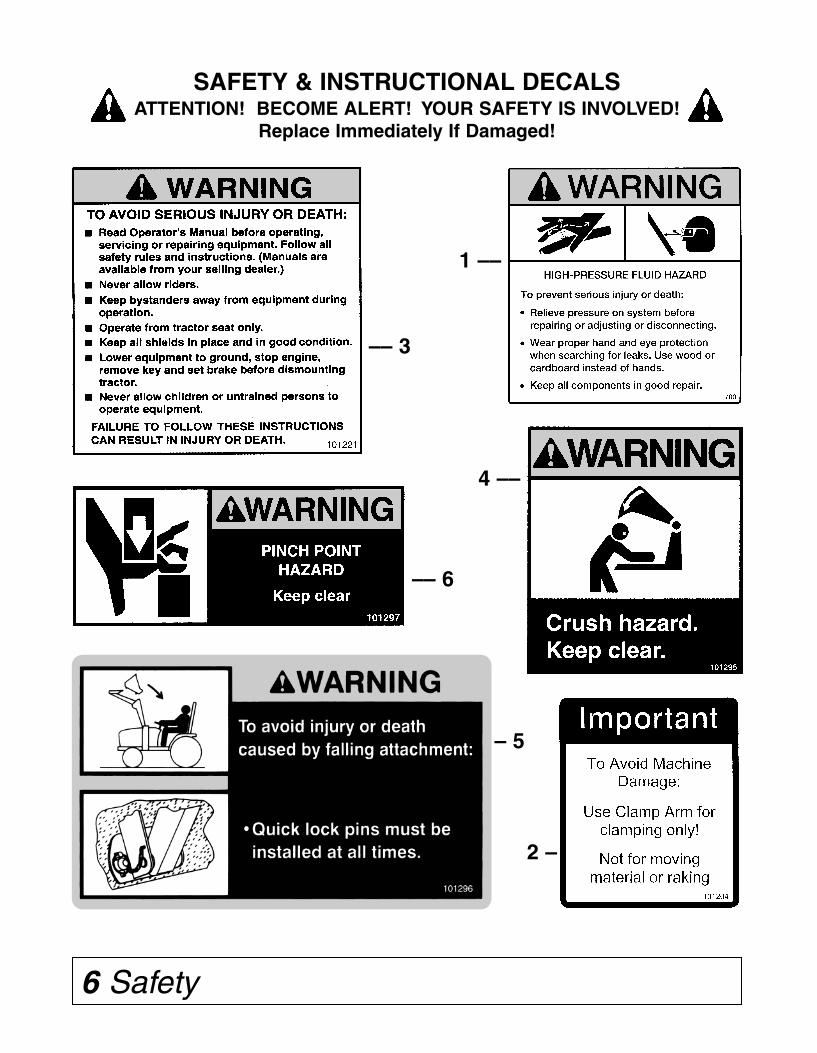
SAFETY & INSTRUCTIONAL DECALSATTENTION! BECOME ALERT! YOUR SAFETY IS INVOLVED!
Replace Immediately If Damaged!
1 ––
4 ––
2 –
–– 3
–– 6
– 5
Parts 27
ROOT GRAPPLE PARTS (Model AV20D)
1 WS812061 Main Frame Weldment (AV20D) 1
2 WS811133 Point, Replaceable Grapple (Weld-On) 6
3 WS811390 Clamp Arm Weldment 2
4 WS811125 Trunnion, Grapple Clamp Arm 4
5 WS811389 Pivot Bolt 1"-8NC x 3" Hex Head Gr.5 (Drilled) 4
6 WS2502009 Washer 1" Springlock 4
7 WS2500001 Nut 1"-8NC Full Hex 4
8 WS2505036 Bushing 2.00 x 1.75 x 0.75 4
9 WS2504049 Zerk, Drive 5/16" 4
10 WS2505690 Hydraulic Cylinder 2.00 x 10 2
11 WS2505035 Bushing 1.25 x 1 x 1 4
12 WS2505672 Hydraulic Hose 1/4" ID x 30" 2
13 WS2505674 Hydraulic Hose 1/4" ID x 42" 2
14 WS2505680 Hydraulic Hose 1/4" ID x 96" 2
15 WS2505681 Hyd. Adapter 90° Adj. Elbow 9/16" to 3/4" 4
16 WS2505682 Hyd. Adapter 90° Swivel Elbow 9/16"M to 9/16"F 2
17 WS2505684 Hyd. Adapter Straight Connector 9/16" to 3/4" 2
18 WS2505685 Hyd. Adapter Tube Tee 9/16"M 2
19 WS2505698 SAE Coupling 1/2" Male 3/4"-16 ORB 2
20 WS2504241 Plate, Tee Hold-Down 1
21 WS2503011 Bolt 3/8"-16NC x 1" Hex Head Gr. 2 1
22 WS2502008 Washer, 3/8" Spring Lock 1
23 WS2504007 Cotter Pin 3/16" x 1 3/4" 4
24 WS2503209 Bolt 3/8"-16NC x 3" Hex Head Gr. 2 3
25 WS2500081 Nut 3/8"-16NC Whiz Flange Hex 3
26 WS831872 Lock Bar 2
27 WS2504070 Roll Pin, 5/16" x 2" 2
28 WS2504224 Roll Pin, 3/8" x 2" 2
29 WS2504195 Roll Pin, 1/2" x 2 1/2" 2
30 WS2504223 Spring, Lock Bar 2
N/S WS812090 Safety Sign/Decal Set 1
Ref.No.
No.Req’d.Part No. Description
Safety 7
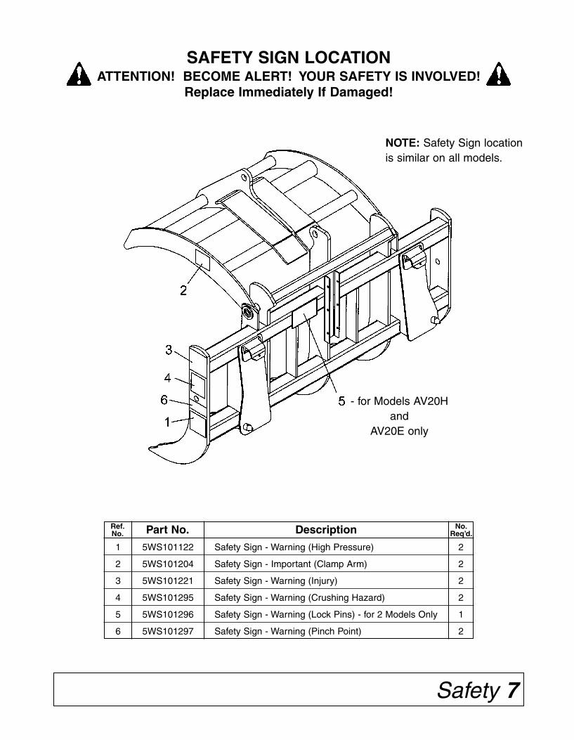
SAFETY SIGN LOCATIONATTENTION! BECOME ALERT! YOUR SAFETY IS INVOLVED!
Replace Immediately If Damaged!
1 5WS101122 Safety Sign - Warning (High Pressure) 2
2 5WS101204 Safety Sign - Important (Clamp Arm) 2
3 5WS101221 Safety Sign - Warning (Injury) 2
4 5WS101295 Safety Sign - Warning (Crushing Hazard) 2
5 5WS101296 Safety Sign - Warning (Lock Pins) - for 2 Models Only 1
6 5WS101297 Safety Sign - Warning (Pinch Point) 2
Ref.No.
No.Req’d.Part No. Description
- for Models AV20Hand
AV20E only
NOTE: Safety Sign locationis similar on all models.
26 Parts
ROOT GRAPPLE PARTS (Model AV20D)
8 Dealer Assembly
DEALER ASSEMBLY(Models AV20H, AV20E, AV20D, AV20G)
Root Grapples are shipped completely assembled.
NOTE: Check customer’s tractor and loader for remote hydraulic outletsmounted on the front of the loader.
If customer’s equipment does not have this option, then it will be nec-essary to install hydraulic lines to the hydraulic remote outlets at the rearof the tractor.
If customer’s tractor is not equipped with hydraulic remote outlets, thenone pair must be installed.
Optional parking stands are available. Stands fit all models – order5WS811395.
Model AV20H only – The Root Grapple is packaged with the hydraulichoses coiled and tied to the hydraulic cylinder.
After removing the Model AV20H from the skid, untie the hydraulichoses and remove the three 3/8” x 3” bolts from the formed channel hoseguide. Locate the hoses into the channel and reinstall the three bolts. Thechannel holds the hoses so they will loop properly at the lower pivot point.
OPTIONAL PARKING STAND INSTALLATION
The pair of parking stands bolt on the back side of the main frame.Locate a stand about 4 inches in from the end on each side of the mainframe. See parts drawing on page 22.
Remove 1/2” carriage bolt from the clevis on the stand bracket. Installthe clevis over the 3 inch square Lower Main Frame tube. Replace thecarriage bolt and tighten.
Install the stand weldment into the bracket and pin in place. NOTE: Forthe model AV20H, install the pin in second hole location from the top ofstand weldment. For all other models, use the top hole.
Be sure to raise the stand legs and pin in the raised position beforeusing the Root Grapple.
Parts 25
ROOT GRAPPLE PARTS (Model AV20E)
1 5WS812041 Main Frame Weldment (AV20E) 1
2 5WS811133 Point, Replaceable Grapple (Weld-On) 5
3 5WS811390 Clamp Arm Weldment 2
4 5WS811125 Trunnion, Grapple Clamp Arm 4
5 5WS811389 Pivot Bolt 1"-8NC x 3" Hex Head Gr. 5 (Drilled) 4
6 5WS2502009 Washer 1" Springlock 4
7 5WS2500001 Nut 1"-8NC Full Hex 4
8 5WS2505036 Bushing, Spring 2.00 x 1.75 x 0.75 4
9 5WS2504049 Zerk, Drive 5/16" 4
10 5WS2505690 Cylinder, Hydraulic 2.00 x 10 2
11 5WS2505035 Bushing, Spring 1.25 x 1.00 x 1.00 4
12 5WS2505671 Hose, Hydraulic 1/4" ID x 24" 2
13 5WS2505673 Hose, Hydraulic 1/4" ID x 36" 2
14 5WS2505679 Hose, Hydraulic 1/4" ID x 84" 2
15 5WS2505681 Hyd. Adapter 90° Adj. Elbow 9/16" to 3/4" 4
16 5WS2505682 Hyd. Adapter 90° Swivel Elbow 9/16"M to 9/16"F 2
17 5WS2505683 Hyd. Adapter Straight Connector 9/16" 2
18 5WS2505685 Hyd. Adapter Tube Tee 9/16"M 2
19 5WS2505686 SAE Coupling 1/4" Male 9/16"-18 ORB 1
20 5WS2505687 SAE Coupling 1/4" Female 9/16"-18 ORB 1
21 5WS2504241 Plate, Tee Hold Down 1
22 5WS2503011 Bolt 3/8"-16NC x 1" Hex Head Gr. 2 1
23 5WS2502008 Washer 3/8" Springlock 1
24 5WS2504007 Cotter Pin 3/16" x 1 3/4" 4
25 5WS2503209 Bolt 3/8"-16NC x 3" Hex Head Gr. 2 3
26 5WS2500081 Nut 3/8”-16NC Whiz Flange Hex 3
N/S 5WS812090 Safety Sign/Decal Set 1
Ref.No.
No.Req’d.Part No. Description

Dealer Check Lists 9
DEALER CHECK LISTS
PRE-DELIVERY CHECK LIST
(Dealer’s responsibility)
Inspect the equipment thoroughly after assembly tobe certain it is set up properly before delivering it tothe customer. The following check list is a reminderof points to inspect. Check off each item if it is foundsatisfactory or after proper adjustment is made.
____ Check that all safety decals are installed and ingood condition. Replace if damaged.
____ Check all bolts to be sure they are tight.
____ Check that all cotter pins and safety pins areproperly installed.
____ Order optional parking stand kit if customerdesires. Order #5WS811395.
DELIVERY CHECK LIST
(Dealer’s Responsibility)
____ Show customer the safe, proper procedures tobe used when mounting, dismounting, andstoring equipment.
____ Show customer how to make adjustments.
____ Present Owner’s/Operator’s Manual andrequest that customer and all operators read itbefore operating equipment. Point out themanual safety rules, explain their meaningsand emphasize the increased safety hazardsthat exist when safety rules are not followed.
____ Point out the safety decals. Explain theirmeaning and the need to keep them in placeand in good condition. Emphasize theincreased safety hazards when instructionsare not followed.
____ Explain to customer the potential crushinghazards of going underneath raised equip-ment. Instruct customer that service work doesnot require going underneath unit and never todo so.
____ Complete the Warranty Registration located onthe Frontier website.
24 Parts
ROOT GRAPPLE PARTS (Model AV20E)
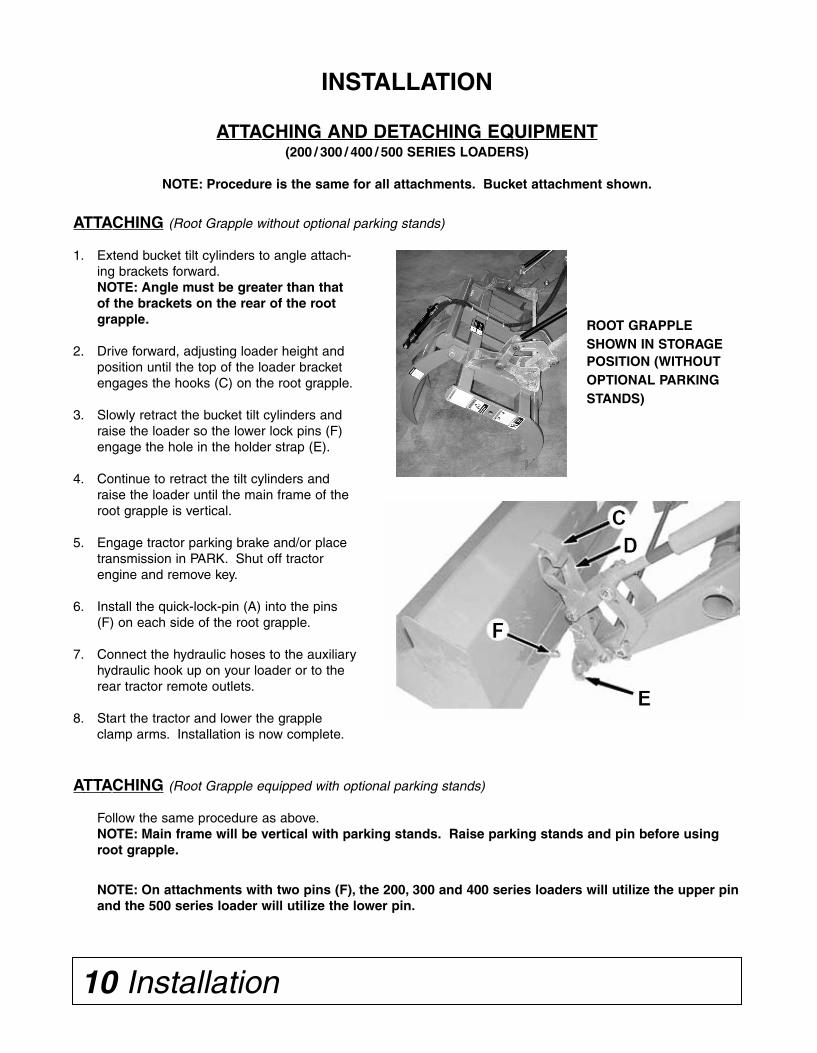
ATTACHING (Root Grapple without optional parking stands)
1. Extend bucket tilt cylinders to angle attach-ing brackets forward.NOTE: Angle must be greater than thatof the brackets on the rear of the rootgrapple.
2. Drive forward, adjusting loader height andposition until the top of the loader bracketengages the hooks (C) on the root grapple.
3. Slowly retract the bucket tilt cylinders andraise the loader so the lower lock pins (F)engage the hole in the holder strap (E).
4. Continue to retract the tilt cylinders andraise the loader until the main frame of theroot grapple is vertical.
5. Engage tractor parking brake and/or placetransmission in PARK. Shut off tractorengine and remove key.
6. Install the quick-lock-pin (A) into the pins(F) on each side of the root grapple.
7. Connect the hydraulic hoses to the auxiliaryhydraulic hook up on your loader or to therear tractor remote outlets.
8. Start the tractor and lower the grappleclamp arms. Installation is now complete.
ATTACHING (Root Grapple equipped with optional parking stands)
Follow the same procedure as above.NOTE: Main frame will be vertical with parking stands. Raise parking stands and pin before usingroot grapple.
NOTE: On attachments with two pins (F), the 200, 300 and 400 series loaders will utilize the upper pinand the 500 series loader will utilize the lower pin.
10 Installation
INSTALLATION
ATTACHING AND DETACHING EQUIPMENT(200 / 300 / 400 / 500 SERIES LOADERS)
NOTE: Procedure is the same for all attachments. Bucket attachment shown.
Parts 23
ROOT GRAPPLE PARTS (Model AV20H)
1 5WS812021 Main Frame Weldment (AV20H) 1
2 5WS811471 Clamp Arm Weldment 1
3 5WS341338 Point, Replaceable Grapple (Weld-On) 5
4 5WS2503309 Bolt, Hex 1"-8NC x 4" Gr. 5 2
5 5WS2500045 Nut, 1"-8NC Hex Nylock 2
6 5WS2504049 Zerk, Drive 5/16" 2
7 5WS2505035 Spring Bushing 1.25 x 1 x 1 2
8 5WS2504007 Pin,Cotter 3/16" x 1 3/4" 2
9 5WS2504230 Cylinder, Hydraulic 2 x 8 ARH 1
10 5WS2505676 Hose, Hydraulic 1/4" ID x 60" 1
11 5WS2505678 Hose,Hydraulic 1/4" lD x 72" 1
12 5WS2505681 Hyd. Adapter 90° Adj. Elbow 9/16" to 3/4" 2
13 5WS2505683 Hyd. Adapter Straight Connector 9/16" 2
14 5WS2505686 SAE Coupling 1/4" Male 9/16"-18 ORB 1
15 5WS2505687 SAE Coupling 1/4" Female 9/16"-18 ORB 1
16 5WS2503209 Bolt 3/8"-16NC x 3" Hex Head Gr. 2 3
17 5WS2500081 Nut 3/8"-I6NC Whiz Flange Hex 3
N/S 5WS812090 Safety Sign/Decal Set 1
Ref.No.
No.Req’d.Part No. Description
ROOT GRAPPLESHOWN IN STORAGEPOSITION (WITHOUTOPTIONAL PARKINGSTANDS)
22 Parts
1 5WS811396 Stand Bracket Weldment 2
2 5WS811398 Stand Tube Weldment 2
3 5WS2503160 Bolt 1/2"-13NC x 4" Carriage Head Gr. 2 2
4 5WS2502002 Washer 1/2" Springlock 2
5 5WS2500003 Nut 1/2"-13NC Full Hex 2
6 5WS343180 Shift Pin w/Clip 1/2" x 3" 2
OPTIONAL STAND KIT(5WS811395)
Optional Stand Kiton Root Grapple
Ref.No.
No.Req’d.Part No. Description
Installation 11
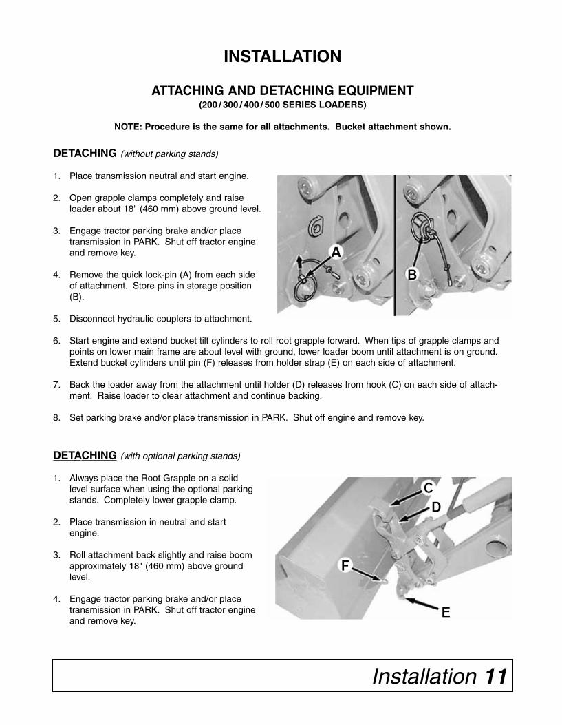
DETACHING (without parking stands)
1. Place transmission neutral and start engine.
2. Open grapple clamps completely and raiseloader about 18" (460 mm) above ground level.
3. Engage tractor parking brake and/or placetransmission in PARK. Shut off tractor engineand remove key.
4. Remove the quick lock-pin (A) from each sideof attachment. Store pins in storage position(B).
5. Disconnect hydraulic couplers to attachment.
6. Start engine and extend bucket tilt cylinders to roll root grapple forward. When tips of grapple clamps andpoints on lower main frame are about level with ground, lower loader boom until attachment is on ground.Extend bucket cylinders until pin (F) releases from holder strap (E) on each side of attachment.
7. Back the loader away from the attachment until holder (D) releases from hook (C) on each side of attach-ment. Raise loader to clear attachment and continue backing.
8. Set parking brake and/or place transmission in PARK. Shut off engine and remove key.
DETACHING (with optional parking stands)
1. Always place the Root Grapple on a solidlevel surface when using the optional parkingstands. Completely lower grapple clamp.
2. Place transmission in neutral and startengine.
3. Roll attachment back slightly and raise boomapproximately 18" (460 mm) above groundlevel.
4. Engage tractor parking brake and/or placetransmission in PARK. Shut off tractor engineand remove key.
INSTALLATION
ATTACHING AND DETACHING EQUIPMENT(200 / 300 / 400 / 500 SERIES LOADERS)
NOTE: Procedure is the same for all attachments. Bucket attachment shown.

Trouble-shooting 21
TROUBLE-SHOOTING GUIDE
PROBLEM POSSIBLE CAUSE POSSIBLE REMEDY
Loader tilt cylinderswon’t pull backafter tilting forward.
1. Loader too small for weight ofmaterial being handled.
2. Hydraulic system not operating atcorrect pressure.
Pick up smaller amounts of material.
Check pressure and adjust or repair.
Hydraulic hosefailure.
1. Hydraulic relief pressure setting isvery high and may cause hydraulichose failure.
2. Hoses are worn or frayed.
3. Hose rating may be too low forhydraulic system pressure.
4. Hose is being pinched by move-ment of loader mount or loaderlinkage.
Check hydraulic system and adjust reliefvalve.
Replace hose.
Replace with higher rated hoses.
Reroute hose and refasten.
Hydraulic oil over-heats.
1. Hydraulic oil level in power unitmay be low.
2. Hydraulic oil or oil filter in powerunit may be dirty.
3. Hydraulic oil reservoir of powerunit may be small.
Check and add oil.
Change oil and filter according to powerunit manufacturer’s recommendations.
Allow time for oil to cool down.
Points come offlower rake tines.
1. Improper operation. Operator is dragging rake backwards onground or operator is wedging rock orin-ground stump between tines – retrainoperator.
ATTACHING EQUIPMENT(600 & 700 SERIES LOADERS WITH QUIK-CHANGE LATCHES)
(Root Grapple without optional parking stands)
1. Extend attachment cylinders to angle attachingbrackets forward.NOTE: Angle must be greater than that ofthe brackets on the rear of the root grapple.
2. 600/700 - Drive forward, adjusting loaderheight and position until the top of the bracketis aligned with the pins (A).
3. Raise loader and retract bucket tilt cylinders toengage lock pins (D). Continue retracting thebucket tilt cylinders until the pins (D) have fullydropped on both sides.
4. Retract bucket cylinders and raise loader untilmain frame of root grapple is vertical.
5. Lower attachment, shut off engine and removekey. Connect hydraulic hoses to the auxiliaryhydraulic hook up on your loader or to the reartractor remote outlets.
6. Lower the grapple clamp arms.
Installation is now complete.
700 SERIES
700 SERIESBOLT-ON LATCHSHOWN
NOTE: Loader with Quik-Change latchplates: Pins/handles on attachment DO NOTneed to be in the UP position for attaching.
CAUTION! ALWAYS CHECK LATCH PINSBEFORE TILTING OR OPERATINGANY ATTACHMENT.
12 Installation
INSTALLATION
ATTACHING AND DETACHING EQUIPMENT (200 / 300 / 400 / 500 SERIES LOADERS)
Continued –
5. Remove the quick lock-pin (A) from each side of attachment. Store pins in storage position (B).
6. Disconnect hydraulic couplers to attachment. Lower the parking stands and pin in place.
7. Start engine and lower the Root Grapple to the ground. Extend bucket tilt cylinders until pin (F) releasesfrom holder strap (E) on each side of attachment. Lower the loader until holder brackets are free from thehooks. Back tractor away from attachment.
8. Set parking brake and/or place transmission in PARK. Shut off engine and remove key.

20 Trouble-shooting
TROUBLE-SHOOTING GUIDE
PROBLEM POSSIBLE CAUSE POSSIBLE REMEDY
Root Grapple clampwill not operate.
1. No or insufficient oil flow. Remote hydraulic connection fittings notcompatible. Check for proper fitting.
Hydraulic system may not be supplyingrated pressure. Consult your dealer.
Hydraulic system may not be delivering itsrated volume of oil due to wear. Hydraulicpump may need to be repaired.
Hydraulic valve on power unit notengaged.
Material slips fromRoot Grapple grasp.
1. Clamp arms not positioned cor-rectly on material.
2. Not firmly clamped by hydrauliccylinder.
3. Hydraulic system has leak – allow-ing clamping pressure to back off.
Reposition clamp arms.
Operate hydraulic cylinder to clamp tighter.
Find leak and repair (could be O-Ring invalve).
Excessive rear tireslippage.
1. Power unit too small.
2. Insufficient traction.
Use larger, heavier power unit or reduceamount handled.
Add rear tire weights or add ballast in tire.Use tractor with FWDA.
Attach heavy implement on rear of tractorfor counter weight.
Bent lower mainframe tines.
1. Improper operation. Operator ramming into in-ground stumpsor rocks – retrain operator.
Operating in frozen ground – trying toloosen material too large to be handled.
Installation 13
INSTALLATION
ATTACHING EQUIPMENT(600 & 700 SERIES LOADERS WITH QUIK-CHANGE LATCHES)
(Root Grapple equipped with optional parking stands)
1. Extend attachment cylinders to angle attaching brack-ets forward.
2. 600/700 - Drive forward, adjusting loader height andposition until the top of the bracket is aligned with thepins (A).
3. Raise loader to engage hooks and retract attachmentcylinders quickly.
4. 600/700 - Raise loader until you can check that pins(D) on both sides have fully dropped.
5. Lower attachment, shut off engine and remove key.Connect hydraulic hoses to the auxiliary hydraulic hookup on your loader or to rear tractor remote outlets.
Pin the parking stands in the raised position.
700 SERIES
700 SERIESBOLT-ONLATCHSHOWN
DETACHING EQUIPMENT(600 & 700 SERIES LOADERS WITH QUIK-CHANGE LATCHES)
NOTE: If using optional parking stands, completely close grapple clamps. Always place unit on a solidlevel surface.
NOTE: If unit is not equipped with optional parking stands, open grapple clamp arms completely.
NOTE: Disconnect hydraulic attachments before backing away.
1. Position the attachment with the main frame about vertical. Place the transmission in PARK and shut offengine and remove key.
2. Lift and rotate latches (A) up on both sides of attachment.
3A. DETACHING (without Parking Stands)
Start tractor and extend bucket tilt cylinders to roll root grapple forward. When tips of grapple clamps andpoints of main frame are about level with ground, lower loader boom until attachment is on ground. Extendbucket cylinders until loader brackets clear latch pin pockets and holder is free from top pins.
3B. DETACHING (with Parking Stands)
Lower parking stands and pin in position. Start tractor and lower attachment to ground. Slowly extend buck-et tilt cylinders until loader brackets clear the latch pin pockets. Lower loader until holder clears the pins.
4. Drive tractor in reverse until loader is clear of the attachment.
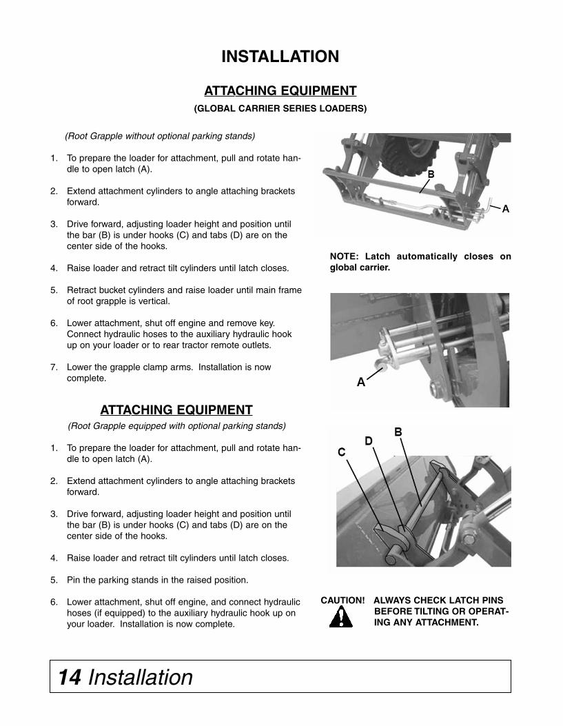
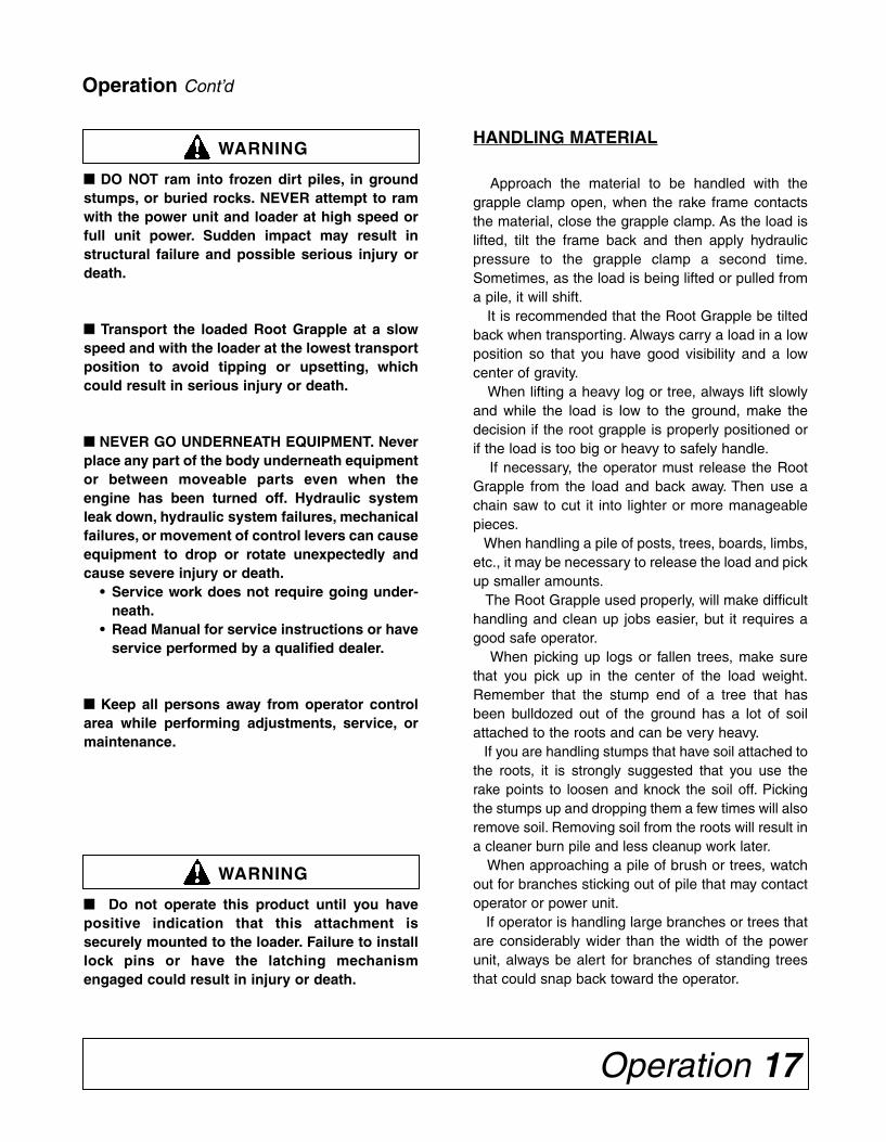
ATTACHING EQUIPMENT(Root Grapple equipped with optional parking stands)
1. To prepare the loader for attachment, pull and rotate han-dle to open latch (A).
2. Extend attachment cylinders to angle attaching bracketsforward.
3. Drive forward, adjusting loader height and position untilthe bar (B) is under hooks (C) and tabs (D) are on thecenter side of the hooks.
4. Raise loader and retract tilt cylinders until latch closes.
5. Pin the parking stands in the raised position.
6. Lower attachment, shut off engine, and connect hydraulichoses (if equipped) to the auxiliary hydraulic hook up onyour loader. Installation is now complete.
Owner Service 19
WARNING
■■ NEVER GO UNDERNEATH EQUIPMENT. Neverplace any part of the body underneath equipmentor between moveable parts even when theengine has been turned off. Hydraulic systemleak down, hydraulic system failures, mechanicalfailures, or movement of control levers can causeequipment to drop or rotate unexpectedly andcause severe injury or death.
• Service work does not require going under-neath.
• Read Manual for service instructions or haveservice performed by a qualified dealer.
WARNING
The information in this section is written for opera-tors who possess basic mechanical skills. If you needhelp, your dealer has trained service techniciansavailable. For your protection, read and follow thesafety information in this manual.
■■ Keep all persons away from operator controlarea while performing adjustments, service, ormaintenance.
■■ Before dismounting power unit or performingany service or maintenance, follow these steps:disengage power to equipment, lower all raisedcomponents to the ground, operate valve leversto release any hydraulic pressure, set parkingbrake, stop engine, remove key, and unfastenseat belt.
WARNING
■■ Never use your hands to locate a hydraulicleak. Use a piece of cardboard or wood. Hydraulicfluid escaping under pressure can penetrateskin. Openings in skin and minor cuts are sus-ceptible to infection from hydraulic fluid. Ifinjured by escaping hydraulic fluid, see a doctorat once. Gangrene and death can result. Withoutimmediate medical treatment, serious infectionand reactions can occur.
MAINTENANCE
Periodically lubricate all pivot points with a goodgrade of grease.
Thoroughly clean the grease zerks before servic-ing. Dirt mixed with lubricant will rapidly wear partsand destroy bearings. Keep it clean.
Replace any worn or damaged parts immediately.Do not use attachment with any damaged parts.Check all bolts to make sure they are properly adjust-ed or tightened.
Check hydraulic hoses and fittings for leaks andreplace or tighten as necessary. Make sure hosesare not being pinched or chafed by movement of unitor loader.
The hardened steel points at the tip of each raketine are replaceable. To replace the point, use a cut-ting torch or hand grinder to cut the welds.
Install the replacement point on the tine and weldin place.
Replace safety decals if damaged or missing.
OWNER SERVICE
STORAGEPOSITION
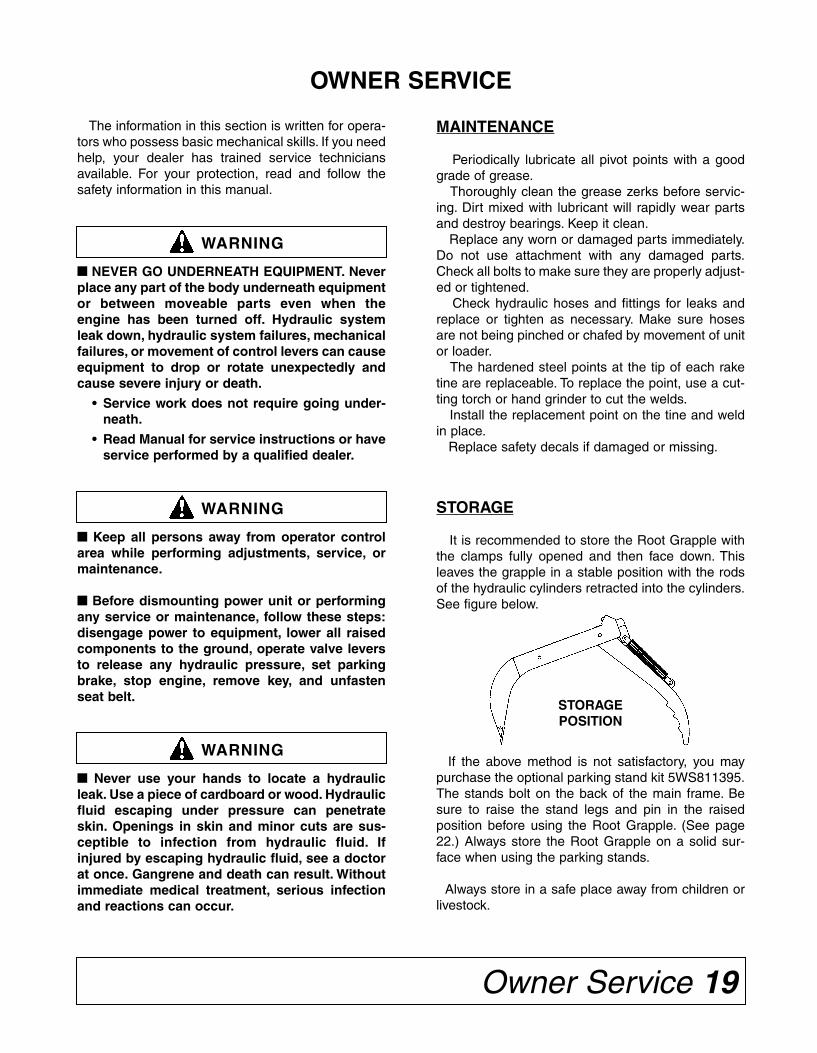
If the above method is not satisfactory, you maypurchase the optional parking stand kit 5WS811395.The stands bolt on the back of the main frame. Besure to raise the stand legs and pin in the raisedposition before using the Root Grapple. (See page22.) Always store the Root Grapple on a solid sur-face when using the parking stands.
Always store in a safe place away from children orlivestock.
STORAGE
It is recommended to store the Root Grapple withthe clamps fully opened and then face down. Thisleaves the grapple in a stable position with the rodsof the hydraulic cylinders retracted into the cylinders.See figure below.
INSTALLATION
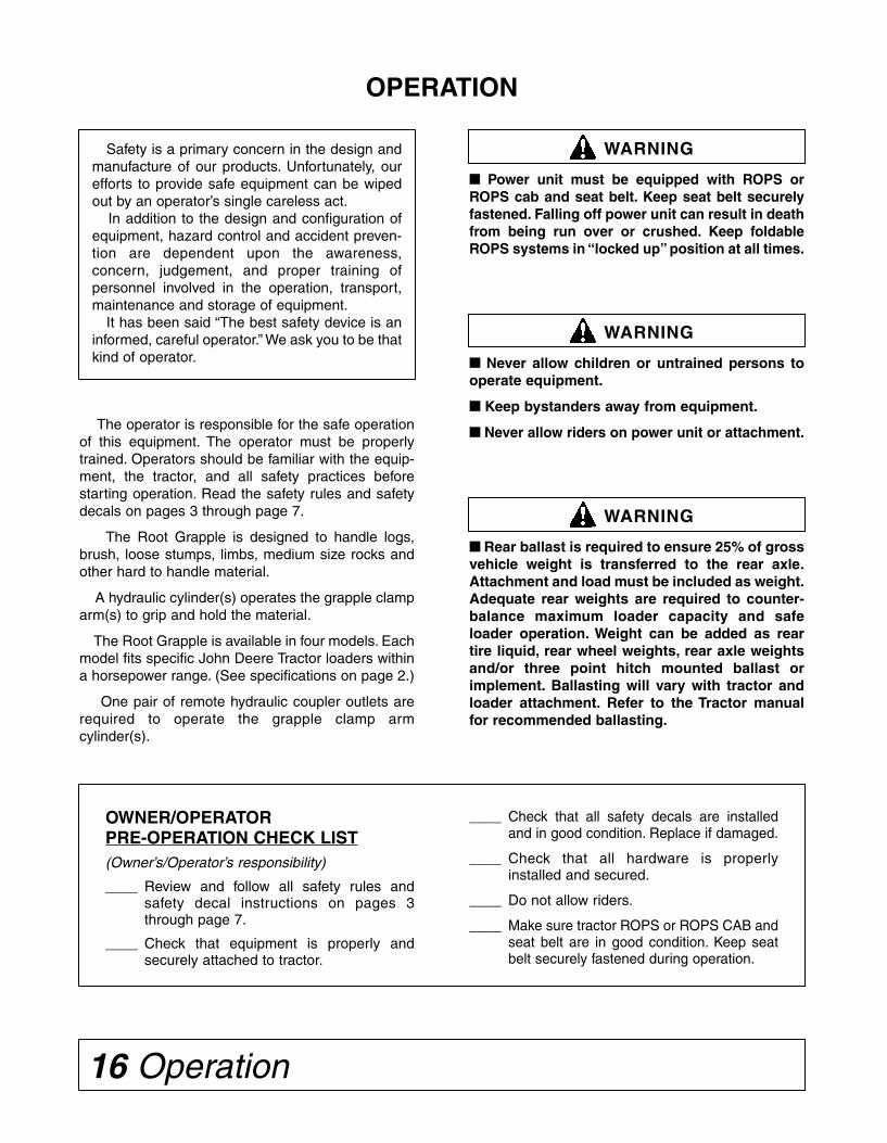
ATTACHING EQUIPMENT(GLOBAL CARRIER SERIES LOADERS)
(Root Grapple without optional parking stands)
1. To prepare the loader for attachment, pull and rotate han-dle to open latch (A).
2. Extend attachment cylinders to angle attaching bracketsforward.
3. Drive forward, adjusting loader height and position untilthe bar (B) is under hooks (C) and tabs (D) are on thecenter side of the hooks.
4. Raise loader and retract tilt cylinders until latch closes.
5. Retract bucket cylinders and raise loader until main frameof root grapple is vertical.
6. Lower attachment, shut off engine and remove key.Connect hydraulic hoses to the auxiliary hydraulic hookup on your loader or to rear tractor remote outlets.
7. Lower the grapple clamp arms. Installation is nowcomplete.
14 Installation
NOTE: Latch automatically closes onglobal carrier.
CAUTION! ALWAYS CHECK LATCH PINSBEFORE TILTING OR OPERAT-ING ANY ATTACHMENT.

18 Operation
WARNING
■■ Keep load centered on Root Grapple andloader. Unbalanced loads increase possibility oftipping or roll-over.
■■ When handling brush or branches, be aware ofbranches that might contact power unit or oper-ator.
■■ When cleaning up old building sites, check forlive utility lines. Always be sure electric, gas, andwater lines have been properly disconnected.
■■ Check material to be handled, especially at oldbuilding sites or dumps. Be alert for anyhazardous material that could be released byroot grapple contact. If in doubt, check withprofessional waste haulers.
■■ When stacking logs, trees, or stumps, alwaysmake sure the load will not roll back toward thepower unit when released from Root Grapple.
Failure to observe the above warnings couldresult in serious injury or death.
CAUTION
■■ Beware of lift clearance when raising loader tomaximum height.
When stacking or loading vehicles, make sureyou are operating in an area AWAY FROM OVER-HEAD WIRES.
DANGER
■■ Beware of low electrical wires when loader israised. Serious injury or death can result if con-tact is made.
Do not leave the operator’s seat if any part ofthe tractor or implement contacts electric lines.
NOTE: If using the optional parking stands, besure to raise the stand legs and pin in the raisedposition before using the Root Grapple.
CAUTION
■■ Always stop the power unit, set brake, shut offengine, remove key, and lower loader to groundbefore attempting to service. Never leave equip-ment unattended with engine running.
Operation Cont’d
NOTE: Root Grapple Limitations
The Root Grapple is designed for handling looselogs, trees, stumps, brush, or other loose material. Itis not designed for heavy bulldozing.
The Root Grapple frame will dig into piles of bull-dozed trees and stumps to consolidate them intofewer piles for more complete burning and final landclearing. The Root Grapple frame is not designed tobulldoze out stumps or buried rocks.
NOTE: To prevent damage to the grapple clamp arm,DO NOT use the grapple clamp to push or lift trees,logs, or stumps. DO NOT use the grapple clamp armto rake or pull material back.
The grapple clamp is designed for holding materialagainst the Root Grapple main frame only. It is NOTbuilt for pushing, pulling, raking, or lifting heavyobjects.
TRANSPORTING
Pay particular close attention to the SafetyMessages regarding handling and transport. Avoidunnecessary injuries and equipment damage byexercising cautious, conscientious travel procedures.
Installation 15
INSTALLATION
DETACHING EQUIPMENT(GLOBAL CARRIER SERIES LOADERS)
NOTE: If using optional parking stands, completely close grapple clamps. Always place unit on a solidlevel surface.
NOTE: If unit is not equipped with optional parking stands, open grapple clamp arms completely.
NOTE: Disconnect hydraulic attachments before backing away.
1. Position the attachment with the main frame aboutvertical.
2. Place the transmission in PARK and shut offengine and remove key.
3. Pull and rotate handle to open latch (A).
4A. DETACHING (without Parking Stands)
Start tractor and extend bucket tilt cylinders to rollroot grapple forward. When tips of grapple clampsand points of main frame are about level withground, lower loader boom until attachment is onground. Extend bucket cylinders until loaderclears latch plate and bar is free from hooks.
4B. DETACHING (with Parking Stands)
Lower parking stands and pin in position.
Start tractor and lower attachment to ground.Slowly extend bucket tilt cylinders until loaderclears the latch plate. Lower loader until barclears the hooks.
5. Drive tractor in reverse until loader is clear of theattachment.
16 Operation
OPERATION
WARNING
Safety is a primary concern in the design andmanufacture of our products. Unfortunately, ourefforts to provide safe equipment can be wipedout by an operator’s single careless act.
In addition to the design and configuration ofequipment, hazard control and accident preven-tion are dependent upon the awareness,concern, judgement, and proper training ofpersonnel involved in the operation, transport,maintenance and storage of equipment.
It has been said “The best safety device is aninformed, careful operator.” We ask you to be thatkind of operator.
OWNER/OPERATORPRE-OPERATION CHECK LIST(Owner’s/Operator’s responsibility)
____ Review and follow all safety rules andsafety decal instructions on pages 3through page 7.
____ Check that equipment is properly andsecurely attached to tractor.
____ Check that all safety decals are installedand in good condition. Replace if damaged.
____ Check that all hardware is properlyinstalled and secured.
____ Do not allow riders.
____ Make sure tractor ROPS or ROPS CAB andseat belt are in good condition. Keep seatbelt securely fastened during operation.
■■ Never allow children or untrained persons tooperate equipment.
■■ Keep bystanders away from equipment.
■■ Never allow riders on power unit or attachment.
WARNING
■■ Power unit must be equipped with ROPS orROPS cab and seat belt. Keep seat belt securelyfastened. Falling off power unit can result in deathfrom being run over or crushed. Keep foldableROPS systems in “locked up” position at all times.
WARNING
■■ Rear ballast is required to ensure 25% of grossvehicle weight is transferred to the rear axle.Attachment and load must be included as weight.Adequate rear weights are required to counter-balance maximum loader capacity and safeloader operation. Weight can be added as reartire liquid, rear wheel weights, rear axle weightsand/or three point hitch mounted ballast orimplement. Ballasting will vary with tractor andloader attachment. Refer to the Tractor manualfor recommended ballasting.
The operator is responsible for the safe operationof this equipment. The operator must be properlytrained. Operators should be familiar with the equip-ment, the tractor, and all safety practices beforestarting operation. Read the safety rules and safetydecals on pages 3 through page 7.
The Root Grapple is designed to handle logs,brush, loose stumps, limbs, medium size rocks andother hard to handle material.
A hydraulic cylinder(s) operates the grapple clamparm(s) to grip and hold the material.
The Root Grapple is available in four models. Eachmodel fits specific John Deere Tractor loaders withina horsepower range. (See specifications on page 2.)
One pair of remote hydraulic coupler outlets arerequired to operate the grapple clamp armcylinder(s).
Operation 17
WARNING
■■ DO NOT ram into frozen dirt piles, in groundstumps, or buried rocks. NEVER attempt to ramwith the power unit and loader at high speed orfull unit power. Sudden impact may result instructural failure and possible serious injury ordeath.
■■ Transport the loaded Root Grapple at a slowspeed and with the loader at the lowest transportposition to avoid tipping or upsetting, whichcould result in serious injury or death.
■■ NEVER GO UNDERNEATH EQUIPMENT. Neverplace any part of the body underneath equipmentor between moveable parts even when theengine has been turned off. Hydraulic systemleak down, hydraulic system failures, mechanicalfailures, or movement of control levers can causeequipment to drop or rotate unexpectedly andcause severe injury or death.
• Service work does not require going under-neath.
• Read Manual for service instructions or haveservice performed by a qualified dealer.
■■ Keep all persons away from operator controlarea while performing adjustments, service, ormaintenance.
WARNING
■■ Do not operate this product until you havepositive indication that this attachment issecurely mounted to the loader. Failure to installlock pins or have the latching mechanismengaged could result in injury or death.
Operation Cont’d
HANDLING MATERIAL
Approach the material to be handled with thegrapple clamp open, when the rake frame contactsthe material, close the grapple clamp. As the load islifted, tilt the frame back and then apply hydraulicpressure to the grapple clamp a second time.Sometimes, as the load is being lifted or pulled froma pile, it will shift.
It is recommended that the Root Grapple be tiltedback when transporting. Always carry a load in a lowposition so that you have good visibility and a lowcenter of gravity.
When lifting a heavy log or tree, always lift slowlyand while the load is low to the ground, make thedecision if the root grapple is properly positioned orif the load is too big or heavy to safely handle.
If necessary, the operator must release the RootGrapple from the load and back away. Then use achain saw to cut it into lighter or more manageablepieces.
When handling a pile of posts, trees, boards, limbs,etc., it may be necessary to release the load and pickup smaller amounts.
The Root Grapple used properly, will make difficulthandling and clean up jobs easier, but it requires agood safe operator.
When picking up logs or fallen trees, make surethat you pick up in the center of the load weight.Remember that the stump end of a tree that hasbeen bulldozed out of the ground has a lot of soilattached to the roots and can be very heavy.
If you are handling stumps that have soil attached tothe roots, it is strongly suggested that you use therake points to loosen and knock the soil off. Pickingthe stumps up and dropping them a few times will alsoremove soil. Removing soil from the roots will result ina cleaner burn pile and less cleanup work later.
When approaching a pile of brush or trees, watchout for branches sticking out of pile that may contactoperator or power unit.
If operator is handling large branches or trees thatare considerably wider than the width of the powerunit, always be alert for branches of standing treesthat could snap back toward the operator.
18 Operation
WARNING
■■ Keep load centered on Root Grapple andloader. Unbalanced loads increase possibility oftipping or roll-over.
■■ When handling brush or branches, be aware ofbranches that might contact power unit or oper-ator.
■■ When cleaning up old building sites, check forlive utility lines. Always be sure electric, gas, andwater lines have been properly disconnected.
■■ Check material to be handled, especially at oldbuilding sites or dumps. Be alert for anyhazardous material that could be released byroot grapple contact. If in doubt, check withprofessional waste haulers.
■■ When stacking logs, trees, or stumps, alwaysmake sure the load will not roll back toward thepower unit when released from Root Grapple.
Failure to observe the above warnings couldresult in serious injury or death.
CAUTION
■■ Beware of lift clearance when raising loader tomaximum height.
When stacking or loading vehicles, make sureyou are operating in an area AWAY FROM OVER-HEAD WIRES.
DANGER
■■ Beware of low electrical wires when loader israised. Serious injury or death can result if con-tact is made.
Do not leave the operator’s seat if any part ofthe tractor or implement contacts electric lines.
NOTE: If using the optional parking stands, besure to raise the stand legs and pin in the raisedposition before using the Root Grapple.
CAUTION
■■ Always stop the power unit, set brake, shut offengine, remove key, and lower loader to groundbefore attempting to service. Never leave equip-ment unattended with engine running.
Operation Cont’d
NOTE: Root Grapple Limitations
The Root Grapple is designed for handling looselogs, trees, stumps, brush, or other loose material. Itis not designed for heavy bulldozing.
The Root Grapple frame will dig into piles of bull-dozed trees and stumps to consolidate them intofewer piles for more complete burning and final landclearing. The Root Grapple frame is not designed tobulldoze out stumps or buried rocks.
NOTE: To prevent damage to the grapple clamp arm,DO NOT use the grapple clamp to push or lift trees,logs, or stumps. DO NOT use the grapple clamp armto rake or pull material back.
The grapple clamp is designed for holding materialagainst the Root Grapple main frame only. It is NOTbuilt for pushing, pulling, raking, or lifting heavyobjects.
TRANSPORTING
Pay particular close attention to the SafetyMessages regarding handling and transport. Avoidunnecessary injuries and equipment damage byexercising cautious, conscientious travel procedures.
Installation 15
INSTALLATION
DETACHING EQUIPMENT(GLOBAL CARRIER SERIES LOADERS)
NOTE: If using optional parking stands, completely close grapple clamps. Always place unit on a solidlevel surface.
NOTE: If unit is not equipped with optional parking stands, open grapple clamp arms completely.
NOTE: Disconnect hydraulic attachments before backing away.
1. Position the attachment with the main frame aboutvertical.
2. Place the transmission in PARK and shut offengine and remove key.
3. Pull and rotate handle to open latch (A).
4A. DETACHING (without Parking Stands)
Start tractor and extend bucket tilt cylinders to rollroot grapple forward. When tips of grapple clampsand points of main frame are about level withground, lower loader boom until attachment is onground. Extend bucket cylinders until loaderclears latch plate and bar is free from hooks.
4B. DETACHING (with Parking Stands)
Lower parking stands and pin in position.
Start tractor and lower attachment to ground.Slowly extend bucket tilt cylinders until loaderclears the latch plate. Lower loader until barclears the hooks.
5. Drive tractor in reverse until loader is clear of theattachment.
ATTACHING EQUIPMENT(Root Grapple equipped with optional parking stands)
1. To prepare the loader for attachment, pull and rotate han-dle to open latch (A).
2. Extend attachment cylinders to angle attaching bracketsforward.
3. Drive forward, adjusting loader height and position untilthe bar (B) is under hooks (C) and tabs (D) are on thecenter side of the hooks.
4. Raise loader and retract tilt cylinders until latch closes.
5. Pin the parking stands in the raised position.
6. Lower attachment, shut off engine, and connect hydraulichoses (if equipped) to the auxiliary hydraulic hook up onyour loader. Installation is now complete.
Owner Service 19
WARNING
■■ NEVER GO UNDERNEATH EQUIPMENT. Neverplace any part of the body underneath equipmentor between moveable parts even when theengine has been turned off. Hydraulic systemleak down, hydraulic system failures, mechanicalfailures, or movement of control levers can causeequipment to drop or rotate unexpectedly andcause severe injury or death.
• Service work does not require going under-neath.
• Read Manual for service instructions or haveservice performed by a qualified dealer.
WARNING
The information in this section is written for opera-tors who possess basic mechanical skills. If you needhelp, your dealer has trained service techniciansavailable. For your protection, read and follow thesafety information in this manual.
■■ Keep all persons away from operator controlarea while performing adjustments, service, ormaintenance.
■■ Before dismounting power unit or performingany service or maintenance, follow these steps:disengage power to equipment, lower all raisedcomponents to the ground, operate valve leversto release any hydraulic pressure, set parkingbrake, stop engine, remove key, and unfastenseat belt.
WARNING
■■ Never use your hands to locate a hydraulicleak. Use a piece of cardboard or wood. Hydraulicfluid escaping under pressure can penetrateskin. Openings in skin and minor cuts are sus-ceptible to infection from hydraulic fluid. Ifinjured by escaping hydraulic fluid, see a doctorat once. Gangrene and death can result. Withoutimmediate medical treatment, serious infectionand reactions can occur.
MAINTENANCE
Periodically lubricate all pivot points with a goodgrade of grease.
Thoroughly clean the grease zerks before servic-ing. Dirt mixed with lubricant will rapidly wear partsand destroy bearings. Keep it clean.
Replace any worn or damaged parts immediately.Do not use attachment with any damaged parts.Check all bolts to make sure they are properly adjust-ed or tightened.
Check hydraulic hoses and fittings for leaks andreplace or tighten as necessary. Make sure hosesare not being pinched or chafed by movement of unitor loader.
The hardened steel points at the tip of each raketine are replaceable. To replace the point, use a cut-ting torch or hand grinder to cut the welds.
Install the replacement point on the tine and weldin place.
Replace safety decals if damaged or missing.
OWNER SERVICE
STORAGEPOSITION
If the above method is not satisfactory, you maypurchase the optional parking stand kit 5WS811395.The stands bolt on the back of the main frame. Besure to raise the stand legs and pin in the raisedposition before using the Root Grapple. (See page22.) Always store the Root Grapple on a solid sur-face when using the parking stands.
Always store in a safe place away from children orlivestock.
STORAGE
It is recommended to store the Root Grapple withthe clamps fully opened and then face down. Thisleaves the grapple in a stable position with the rodsof the hydraulic cylinders retracted into the cylinders.See figure below.
INSTALLATION
ATTACHING EQUIPMENT(GLOBAL CARRIER SERIES LOADERS)
(Root Grapple without optional parking stands)
1. To prepare the loader for attachment, pull and rotate han-dle to open latch (A).
2. Extend attachment cylinders to angle attaching bracketsforward.
3. Drive forward, adjusting loader height and position untilthe bar (B) is under hooks (C) and tabs (D) are on thecenter side of the hooks.
4. Raise loader and retract tilt cylinders until latch closes.
5. Retract bucket cylinders and raise loader until main frameof root grapple is vertical.
6. Lower attachment, shut off engine and remove key.Connect hydraulic hoses to the auxiliary hydraulic hookup on your loader or to rear tractor remote outlets.
7. Lower the grapple clamp arms. Installation is nowcomplete.
14 Installation
NOTE: Latch automatically closes onglobal carrier.
CAUTION! ALWAYS CHECK LATCH PINSBEFORE TILTING OR OPERAT-ING ANY ATTACHMENT.

20 Trouble-shooting
TROUBLE-SHOOTING GUIDE
PROBLEM POSSIBLE CAUSE POSSIBLE REMEDY
Root Grapple clampwill not operate.
1. No or insufficient oil flow. Remote hydraulic connection fittings notcompatible. Check for proper fitting.
Hydraulic system may not be supplyingrated pressure. Consult your dealer.
Hydraulic system may not be delivering itsrated volume of oil due to wear. Hydraulicpump may need to be repaired.
Hydraulic valve on power unit notengaged.
Material slips fromRoot Grapple grasp.
1. Clamp arms not positioned cor-rectly on material.
2. Not firmly clamped by hydrauliccylinder.
3. Hydraulic system has leak – allow-ing clamping pressure to back off.
Reposition clamp arms.
Operate hydraulic cylinder to clamp tighter.
Find leak and repair (could be O-Ring invalve).
Excessive rear tireslippage.
1. Power unit too small.
2. Insufficient traction.
Use larger, heavier power unit or reduceamount handled.
Add rear tire weights or add ballast in tire.Use tractor with FWDA.
Attach heavy implement on rear of tractorfor counter weight.
Bent lower mainframe tines.
1. Improper operation. Operator ramming into in-ground stumpsor rocks – retrain operator.
Operating in frozen ground – trying toloosen material too large to be handled.
Installation 13
INSTALLATION
ATTACHING EQUIPMENT(600 & 700 SERIES LOADERS WITH QUIK-CHANGE LATCHES)
(Root Grapple equipped with optional parking stands)
1. Extend attachment cylinders to angle attaching brack-ets forward.
2. 600/700 - Drive forward, adjusting loader height andposition until the top of the bracket is aligned with thepins (A).
3. Raise loader to engage hooks and retract attachmentcylinders quickly.
4. 600/700 - Raise loader until you can check that pins(D) on both sides have fully dropped.
5. Lower attachment, shut off engine and remove key.Connect hydraulic hoses to the auxiliary hydraulic hookup on your loader or to rear tractor remote outlets.
Pin the parking stands in the raised position.
700 SERIES
700 SERIESBOLT-ONLATCHSHOWN
DETACHING EQUIPMENT(600 & 700 SERIES LOADERS WITH QUIK-CHANGE LATCHES)
NOTE: If using optional parking stands, completely close grapple clamps. Always place unit on a solidlevel surface.
NOTE: If unit is not equipped with optional parking stands, open grapple clamp arms completely.
NOTE: Disconnect hydraulic attachments before backing away.
1. Position the attachment with the main frame about vertical. Place the transmission in PARK and shut offengine and remove key.
2. Lift and rotate latches (A) up on both sides of attachment.
3A. DETACHING (without Parking Stands)
Start tractor and extend bucket tilt cylinders to roll root grapple forward. When tips of grapple clamps andpoints of main frame are about level with ground, lower loader boom until attachment is on ground. Extendbucket cylinders until loader brackets clear latch pin pockets and holder is free from top pins.
3B. DETACHING (with Parking Stands)
Lower parking stands and pin in position. Start tractor and lower attachment to ground. Slowly extend buck-et tilt cylinders until loader brackets clear the latch pin pockets. Lower loader until holder clears the pins.
4. Drive tractor in reverse until loader is clear of the attachment.

Trouble-shooting 21
TROUBLE-SHOOTING GUIDE
PROBLEM POSSIBLE CAUSE POSSIBLE REMEDY
Loader tilt cylinderswon’t pull backafter tilting forward.
1. Loader too small for weight ofmaterial being handled.
2. Hydraulic system not operating atcorrect pressure.
Pick up smaller amounts of material.
Check pressure and adjust or repair.
Hydraulic hosefailure.
1. Hydraulic relief pressure setting isvery high and may cause hydraulichose failure.
2. Hoses are worn or frayed.
3. Hose rating may be too low forhydraulic system pressure.
4. Hose is being pinched by move-ment of loader mount or loaderlinkage.
Check hydraulic system and adjust reliefvalve.
Replace hose.
Replace with higher rated hoses.
Reroute hose and refasten.
Hydraulic oil over-heats.
1. Hydraulic oil level in power unitmay be low.
2. Hydraulic oil or oil filter in powerunit may be dirty.
3. Hydraulic oil reservoir of powerunit may be small.
Check and add oil.
Change oil and filter according to powerunit manufacturer’s recommendations.
Allow time for oil to cool down.
Points come offlower rake tines.
1. Improper operation. Operator is dragging rake backwards onground or operator is wedging rock orin-ground stump between tines – retrainoperator.
ATTACHING EQUIPMENT(600 & 700 SERIES LOADERS WITH QUIK-CHANGE LATCHES)
(Root Grapple without optional parking stands)
1. Extend attachment cylinders to angle attachingbrackets forward.NOTE: Angle must be greater than that ofthe brackets on the rear of the root grapple.
2. 600/700 - Drive forward, adjusting loaderheight and position until the top of the bracketis aligned with the pins (A).
3. Raise loader and retract bucket tilt cylinders toengage lock pins (D). Continue retracting thebucket tilt cylinders until the pins (D) have fullydropped on both sides.
4. Retract bucket cylinders and raise loader untilmain frame of root grapple is vertical.
5. Lower attachment, shut off engine and removekey. Connect hydraulic hoses to the auxiliaryhydraulic hook up on your loader or to the reartractor remote outlets.
6. Lower the grapple clamp arms.
Installation is now complete.
700 SERIES
700 SERIESBOLT-ON LATCHSHOWN
NOTE: Loader with Quik-Change latchplates: Pins/handles on attachment DO NOTneed to be in the UP position for attaching.
CAUTION! ALWAYS CHECK LATCH PINSBEFORE TILTING OR OPERATINGANY ATTACHMENT.
12 Installation
INSTALLATION
ATTACHING AND DETACHING EQUIPMENT (200 / 300 / 400 / 500 SERIES LOADERS)
Continued –
5. Remove the quick lock-pin (A) from each side of attachment. Store pins in storage position (B).
6. Disconnect hydraulic couplers to attachment. Lower the parking stands and pin in place.
7. Start engine and lower the Root Grapple to the ground. Extend bucket tilt cylinders until pin (F) releasesfrom holder strap (E) on each side of attachment. Lower the loader until holder brackets are free from thehooks. Back tractor away from attachment.
8. Set parking brake and/or place transmission in PARK. Shut off engine and remove key.
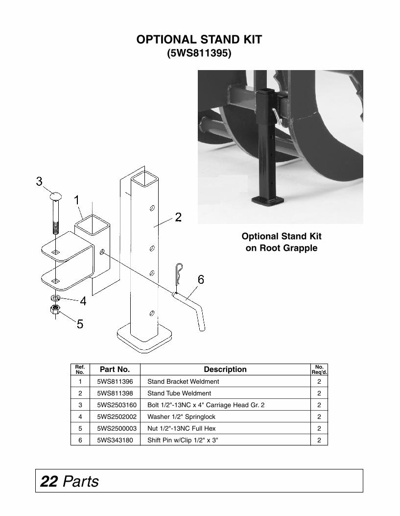
22 Parts
1 5WS811396 Stand Bracket Weldment 2
2 5WS811398 Stand Tube Weldment 2
3 5WS2503160 Bolt 1/2"-13NC x 4" Carriage Head Gr. 2 2
4 5WS2502002 Washer 1/2" Springlock 2
5 5WS2500003 Nut 1/2"-13NC Full Hex 2
6 5WS343180 Shift Pin w/Clip 1/2" x 3" 2
OPTIONAL STAND KIT(5WS811395)
Optional Stand Kiton Root Grapple
Ref.No.
No.Req’d.Part No. Description
Installation 11
DETACHING (without parking stands)
1. Place transmission neutral and start engine.
2. Open grapple clamps completely and raiseloader about 18" (460 mm) above ground level.
3. Engage tractor parking brake and/or placetransmission in PARK. Shut off tractor engineand remove key.
4. Remove the quick lock-pin (A) from each sideof attachment. Store pins in storage position(B).
5. Disconnect hydraulic couplers to attachment.
6. Start engine and extend bucket tilt cylinders to roll root grapple forward. When tips of grapple clamps andpoints on lower main frame are about level with ground, lower loader boom until attachment is on ground.Extend bucket cylinders until pin (F) releases from holder strap (E) on each side of attachment.
7. Back the loader away from the attachment until holder (D) releases from hook (C) on each side of attach-ment. Raise loader to clear attachment and continue backing.
8. Set parking brake and/or place transmission in PARK. Shut off engine and remove key.
DETACHING (with optional parking stands)
1. Always place the Root Grapple on a solidlevel surface when using the optional parkingstands. Completely lower grapple clamp.
2. Place transmission in neutral and startengine.
3. Roll attachment back slightly and raise boomapproximately 18" (460 mm) above groundlevel.
4. Engage tractor parking brake and/or placetransmission in PARK. Shut off tractor engineand remove key.
INSTALLATION
ATTACHING AND DETACHING EQUIPMENT(200 / 300 / 400 / 500 SERIES LOADERS)
NOTE: Procedure is the same for all attachments. Bucket attachment shown.
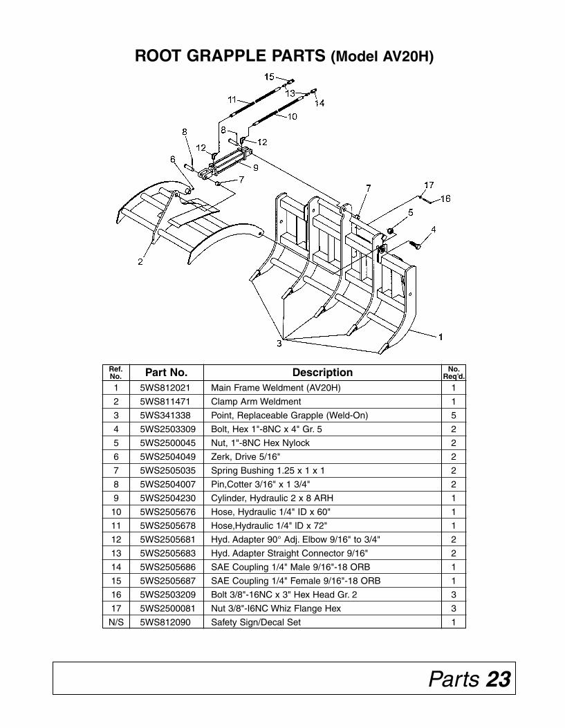
ATTACHING (Root Grapple without optional parking stands)
1. Extend bucket tilt cylinders to angle attach-ing brackets forward.NOTE: Angle must be greater than thatof the brackets on the rear of the rootgrapple.
2. Drive forward, adjusting loader height andposition until the top of the loader bracketengages the hooks (C) on the root grapple.
3. Slowly retract the bucket tilt cylinders andraise the loader so the lower lock pins (F)engage the hole in the holder strap (E).
4. Continue to retract the tilt cylinders andraise the loader until the main frame of theroot grapple is vertical.
5. Engage tractor parking brake and/or placetransmission in PARK. Shut off tractorengine and remove key.
6. Install the quick-lock-pin (A) into the pins(F) on each side of the root grapple.
7. Connect the hydraulic hoses to the auxiliaryhydraulic hook up on your loader or to therear tractor remote outlets.
8. Start the tractor and lower the grappleclamp arms. Installation is now complete.
ATTACHING (Root Grapple equipped with optional parking stands)
Follow the same procedure as above.NOTE: Main frame will be vertical with parking stands. Raise parking stands and pin before usingroot grapple.
NOTE: On attachments with two pins (F), the 200, 300 and 400 series loaders will utilize the upper pinand the 500 series loader will utilize the lower pin.
10 Installation
INSTALLATION
ATTACHING AND DETACHING EQUIPMENT(200 / 300 / 400 / 500 SERIES LOADERS)
NOTE: Procedure is the same for all attachments. Bucket attachment shown.
Parts 23
ROOT GRAPPLE PARTS (Model AV20H)
1 5WS812021 Main Frame Weldment (AV20H) 1
2 5WS811471 Clamp Arm Weldment 1
3 5WS341338 Point, Replaceable Grapple (Weld-On) 5
4 5WS2503309 Bolt, Hex 1"-8NC x 4" Gr. 5 2
5 5WS2500045 Nut, 1"-8NC Hex Nylock 2
6 5WS2504049 Zerk, Drive 5/16" 2
7 5WS2505035 Spring Bushing 1.25 x 1 x 1 2
8 5WS2504007 Pin,Cotter 3/16" x 1 3/4" 2
9 5WS2504230 Cylinder, Hydraulic 2 x 8 ARH 1
10 5WS2505676 Hose, Hydraulic 1/4" ID x 60" 1
11 5WS2505678 Hose,Hydraulic 1/4" lD x 72" 1
12 5WS2505681 Hyd. Adapter 90° Adj. Elbow 9/16" to 3/4" 2
13 5WS2505683 Hyd. Adapter Straight Connector 9/16" 2
14 5WS2505686 SAE Coupling 1/4" Male 9/16"-18 ORB 1
15 5WS2505687 SAE Coupling 1/4" Female 9/16"-18 ORB 1
16 5WS2503209 Bolt 3/8"-16NC x 3" Hex Head Gr. 2 3
17 5WS2500081 Nut 3/8"-I6NC Whiz Flange Hex 3
N/S 5WS812090 Safety Sign/Decal Set 1
Ref.No.
No.Req’d.Part No. Description
ROOT GRAPPLESHOWN IN STORAGEPOSITION (WITHOUTOPTIONAL PARKINGSTANDS)
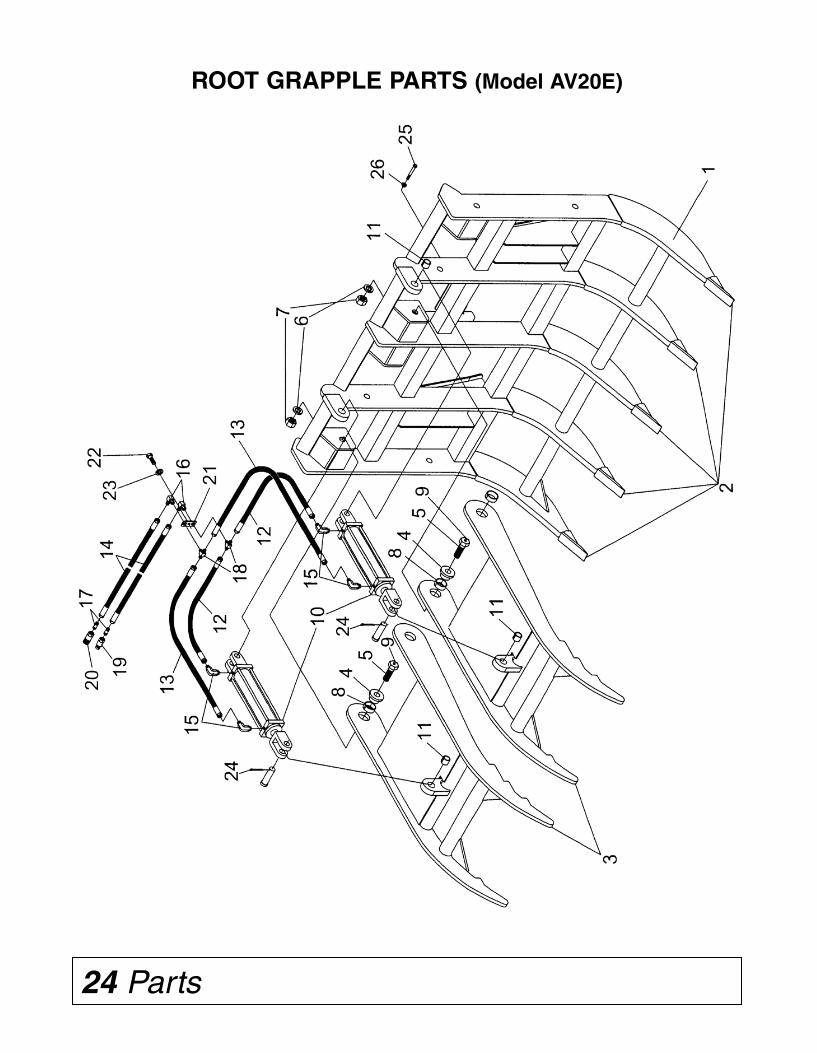
Dealer Check Lists 9
DEALER CHECK LISTS
PRE-DELIVERY CHECK LIST
(Dealer’s responsibility)
Inspect the equipment thoroughly after assembly tobe certain it is set up properly before delivering it tothe customer. The following check list is a reminderof points to inspect. Check off each item if it is foundsatisfactory or after proper adjustment is made.
____ Check that all safety decals are installed and ingood condition. Replace if damaged.
____ Check all bolts to be sure they are tight.
____ Check that all cotter pins and safety pins areproperly installed.
____ Order optional parking stand kit if customerdesires. Order #5WS811395.
DELIVERY CHECK LIST
(Dealer’s Responsibility)
____ Show customer the safe, proper procedures tobe used when mounting, dismounting, andstoring equipment.
____ Show customer how to make adjustments.
____ Present Owner’s/Operator’s Manual andrequest that customer and all operators read itbefore operating equipment. Point out themanual safety rules, explain their meaningsand emphasize the increased safety hazardsthat exist when safety rules are not followed.
____ Point out the safety decals. Explain theirmeaning and the need to keep them in placeand in good condition. Emphasize theincreased safety hazards when instructionsare not followed.
____ Explain to customer the potential crushinghazards of going underneath raised equip-ment. Instruct customer that service work doesnot require going underneath unit and never todo so.
____ Complete the Warranty Registration located onthe Frontier website.
24 Parts
ROOT GRAPPLE PARTS (Model AV20E)
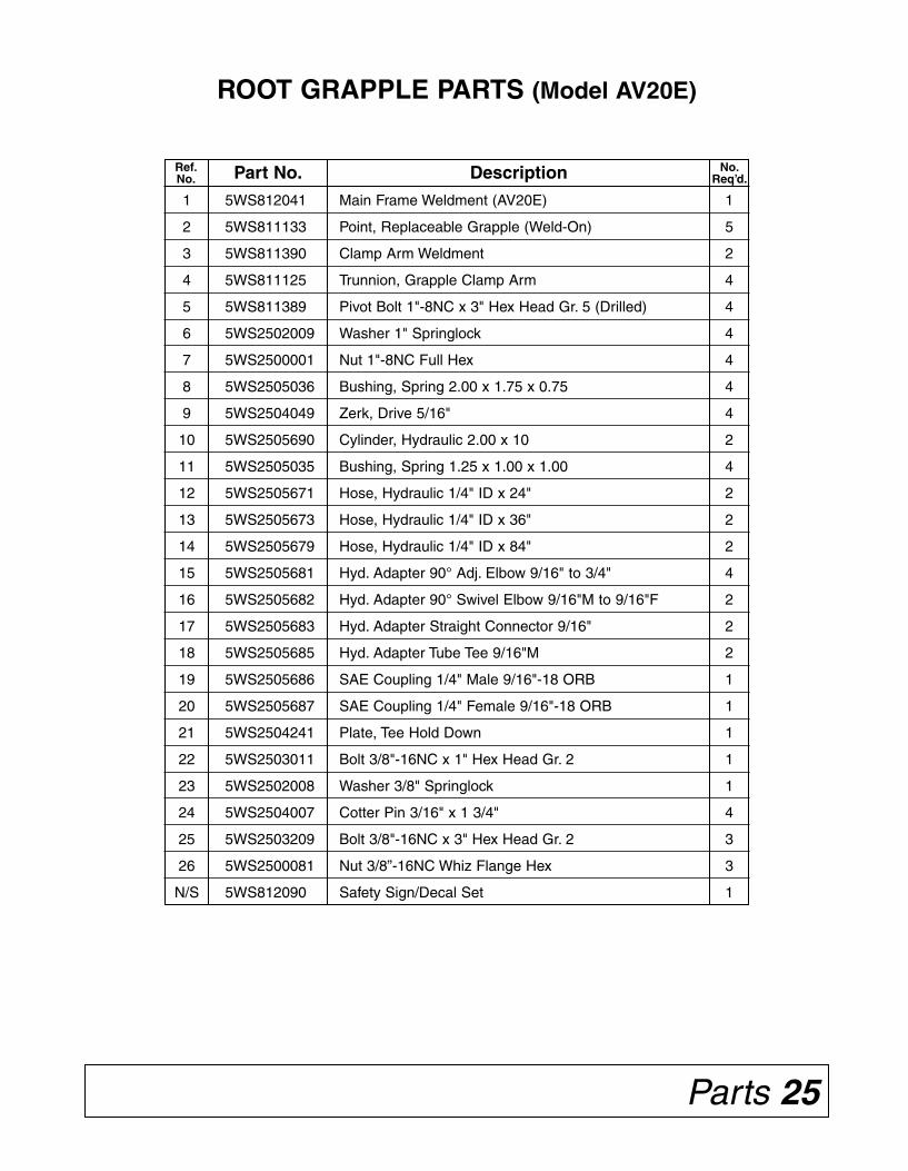
8 Dealer Assembly
DEALER ASSEMBLY(Models AV20H, AV20E, AV20D, AV20G)
Root Grapples are shipped completely assembled.
NOTE: Check customer’s tractor and loader for remote hydraulic outletsmounted on the front of the loader.
If customer’s equipment does not have this option, then it will be nec-essary to install hydraulic lines to the hydraulic remote outlets at the rearof the tractor.
If customer’s tractor is not equipped with hydraulic remote outlets, thenone pair must be installed.
Optional parking stands are available. Stands fit all models – order5WS811395.
Model AV20H only – The Root Grapple is packaged with the hydraulichoses coiled and tied to the hydraulic cylinder.
After removing the Model AV20H from the skid, untie the hydraulichoses and remove the three 3/8” x 3” bolts from the formed channel hoseguide. Locate the hoses into the channel and reinstall the three bolts. Thechannel holds the hoses so they will loop properly at the lower pivot point.
OPTIONAL PARKING STAND INSTALLATION
The pair of parking stands bolt on the back side of the main frame.Locate a stand about 4 inches in from the end on each side of the mainframe. See parts drawing on page 22.
Remove 1/2” carriage bolt from the clevis on the stand bracket. Installthe clevis over the 3 inch square Lower Main Frame tube. Replace thecarriage bolt and tighten.
Install the stand weldment into the bracket and pin in place. NOTE: Forthe model AV20H, install the pin in second hole location from the top ofstand weldment. For all other models, use the top hole.
Be sure to raise the stand legs and pin in the raised position beforeusing the Root Grapple.
Parts 25
ROOT GRAPPLE PARTS (Model AV20E)
1 5WS812041 Main Frame Weldment (AV20E) 1
2 5WS811133 Point, Replaceable Grapple (Weld-On) 5
3 5WS811390 Clamp Arm Weldment 2
4 5WS811125 Trunnion, Grapple Clamp Arm 4
5 5WS811389 Pivot Bolt 1"-8NC x 3" Hex Head Gr. 5 (Drilled) 4
6 5WS2502009 Washer 1" Springlock 4
7 5WS2500001 Nut 1"-8NC Full Hex 4
8 5WS2505036 Bushing, Spring 2.00 x 1.75 x 0.75 4
9 5WS2504049 Zerk, Drive 5/16" 4
10 5WS2505690 Cylinder, Hydraulic 2.00 x 10 2
11 5WS2505035 Bushing, Spring 1.25 x 1.00 x 1.00 4
12 5WS2505671 Hose, Hydraulic 1/4" ID x 24" 2
13 5WS2505673 Hose, Hydraulic 1/4" ID x 36" 2
14 5WS2505679 Hose, Hydraulic 1/4" ID x 84" 2
15 5WS2505681 Hyd. Adapter 90° Adj. Elbow 9/16" to 3/4" 4
16 5WS2505682 Hyd. Adapter 90° Swivel Elbow 9/16"M to 9/16"F 2
17 5WS2505683 Hyd. Adapter Straight Connector 9/16" 2
18 5WS2505685 Hyd. Adapter Tube Tee 9/16"M 2
19 5WS2505686 SAE Coupling 1/4" Male 9/16"-18 ORB 1
20 5WS2505687 SAE Coupling 1/4" Female 9/16"-18 ORB 1
21 5WS2504241 Plate, Tee Hold Down 1
22 5WS2503011 Bolt 3/8"-16NC x 1" Hex Head Gr. 2 1
23 5WS2502008 Washer 3/8" Springlock 1
24 5WS2504007 Cotter Pin 3/16" x 1 3/4" 4
25 5WS2503209 Bolt 3/8"-16NC x 3" Hex Head Gr. 2 3
26 5WS2500081 Nut 3/8”-16NC Whiz Flange Hex 3
N/S 5WS812090 Safety Sign/Decal Set 1
Ref.No.
No.Req’d.Part No. Description
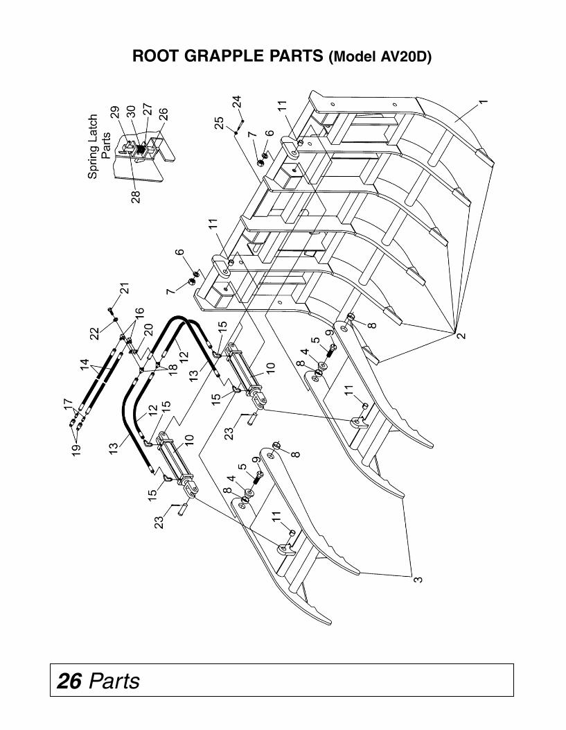
Safety 7
SAFETY SIGN LOCATIONATTENTION! BECOME ALERT! YOUR SAFETY IS INVOLVED!
Replace Immediately If Damaged!
1 5WS101122 Safety Sign - Warning (High Pressure) 2
2 5WS101204 Safety Sign - Important (Clamp Arm) 2
3 5WS101221 Safety Sign - Warning (Injury) 2
4 5WS101295 Safety Sign - Warning (Crushing Hazard) 2
5 5WS101296 Safety Sign - Warning (Lock Pins) - for 2 Models Only 1
6 5WS101297 Safety Sign - Warning (Pinch Point) 2
Ref.No.
No.Req’d.Part No. Description
- for Models AV20Hand
AV20E only
NOTE: Safety Sign locationis similar on all models.
26 Parts
ROOT GRAPPLE PARTS (Model AV20D)
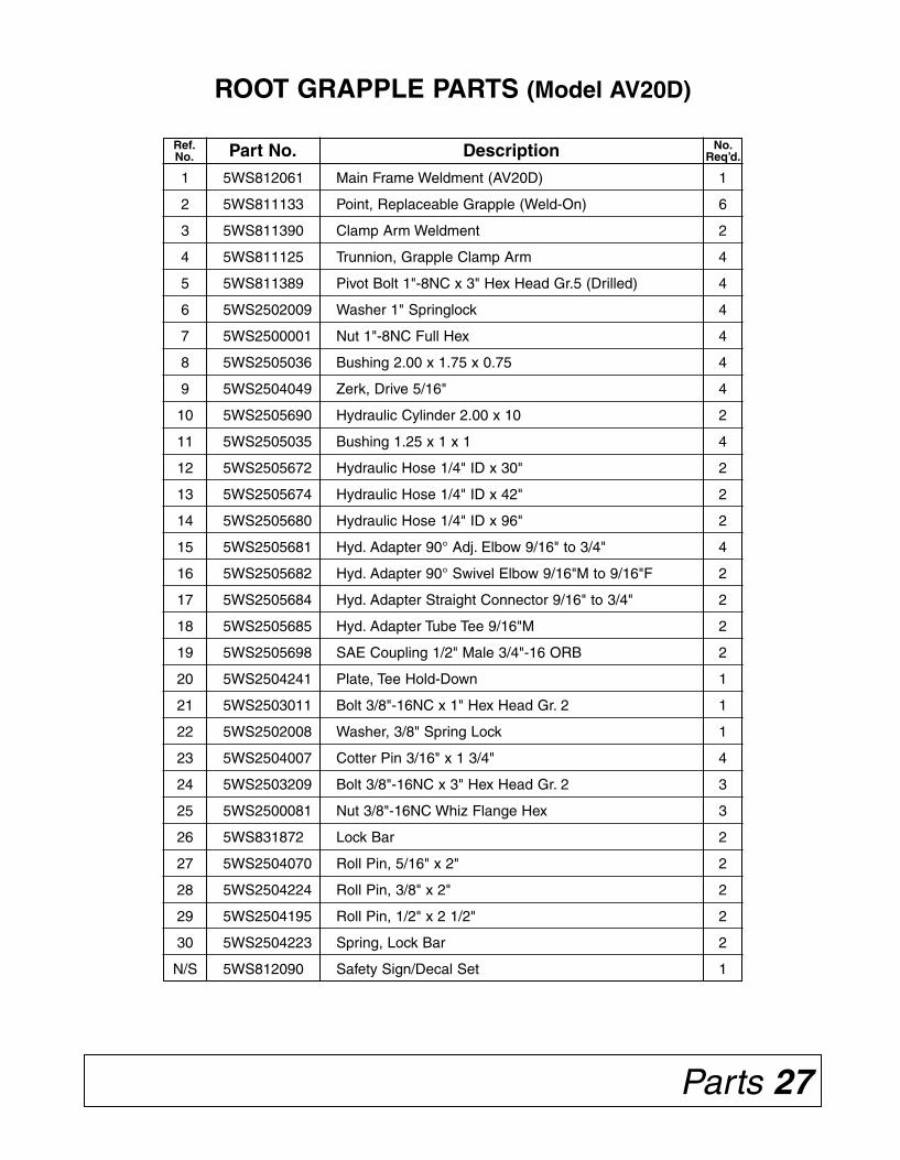
6 Safety
SAFETY & INSTRUCTIONAL DECALSATTENTION! BECOME ALERT! YOUR SAFETY IS INVOLVED!
Replace Immediately If Damaged!
1 ––
4 ––
2 –
–– 3
–– 6
– 5
Parts 27
ROOT GRAPPLE PARTS (Model AV20D)
1 5WS812061 Main Frame Weldment (AV20D) 1
2 5WS811133 Point, Replaceable Grapple (Weld-On) 6
3 5WS811390 Clamp Arm Weldment 2
4 5WS811125 Trunnion, Grapple Clamp Arm 4
5 5WS811389 Pivot Bolt 1"-8NC x 3" Hex Head Gr.5 (Drilled) 4
6 5WS2502009 Washer 1" Springlock 4
7 5WS2500001 Nut 1"-8NC Full Hex 4
8 5WS2505036 Bushing 2.00 x 1.75 x 0.75 4
9 5WS2504049 Zerk, Drive 5/16" 4
10 5WS2505690 Hydraulic Cylinder 2.00 x 10 2
11 5WS2505035 Bushing 1.25 x 1 x 1 4
12 5WS2505672 Hydraulic Hose 1/4" ID x 30" 2
13 5WS2505674 Hydraulic Hose 1/4" ID x 42" 2
14 5WS2505680 Hydraulic Hose 1/4" ID x 96" 2
15 5WS2505681 Hyd. Adapter 90° Adj. Elbow 9/16" to 3/4" 4
16 5WS2505682 Hyd. Adapter 90° Swivel Elbow 9/16"M to 9/16"F 2
17 5WS2505684 Hyd. Adapter Straight Connector 9/16" to 3/4" 2
18 5WS2505685 Hyd. Adapter Tube Tee 9/16"M 2
19 5WS2505698 SAE Coupling 1/2" Male 3/4"-16 ORB 2
20 5WS2504241 Plate, Tee Hold-Down 1
21 5WS2503011 Bolt 3/8"-16NC x 1" Hex Head Gr. 2 1
22 5WS2502008 Washer, 3/8" Spring Lock 1
23 5WS2504007 Cotter Pin 3/16" x 1 3/4" 4
24 5WS2503209 Bolt 3/8"-16NC x 3" Hex Head Gr. 2 3
25 5WS2500081 Nut 3/8"-16NC Whiz Flange Hex 3
26 5WS831872 Lock Bar 2
27 5WS2504070 Roll Pin, 5/16" x 2" 2
28 5WS2504224 Roll Pin, 3/8" x 2" 2
29 5WS2504195 Roll Pin, 1/2" x 2 1/2" 2
30 5WS2504223 Spring, Lock Bar 2
N/S 5WS812090 Safety Sign/Decal Set 1
Ref.No.
No.Req’d.Part No. Description
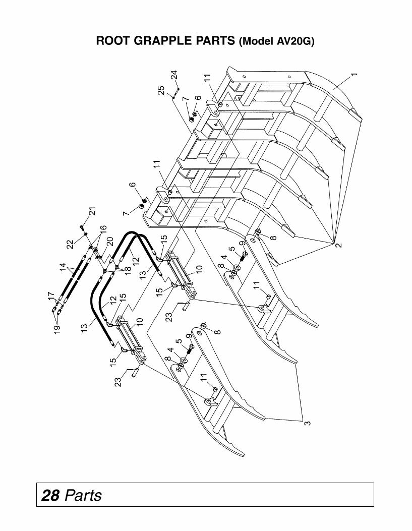
Safety 5
SAFETY RULESATTENTION! BECOME ALERT! YOUR SAFETY IS INVOLVED!
OPERATION (cont’d from previous page)■■ Do not operate or transport equipment whileunder the influence of alcohol or drugs. Consultyour doctor about operating this machine whiletaking prescription medications.
■■ Always check locking pins before tilting oroperating any attachment.
■■ Do not handle round bales with Root Grapple.
■■ Do not detach loader from tractor with RootGrapple installed. Equip loader with materialbucket when detaching.
■■ Add the required amount of ballast on tractor.(See Preparing the Tractor section of the LoaderOperator's Manual to determine the type andamount of ballast required.)
MAINTENANCE■■ Always wear relatively tight and belted clothingto avoid getting caught in moving parts. Wearsturdy, rough-soled work shoes and protectiveequipment for eyes, hair, hands, hearing, andhead; and respirator or filter mask whereappropriate.
■■ Never go underneath equipment (lowered tothe ground or raised) unless it is properlyblocked and secured. Never place any part of thebody underneath equipment or between move-able parts even when the engine has been turnedoff. Hydraulic system leak down, hydraulic sys-tem failures, mechanical failures, or movement ofcontrol levers can cause equipment to drop orrotate unexpectedly and cause severe injury ordeath.
■■ Make sure attachment is properly secured,adjusted, and in good operating condition.
■■ Before leaving operator’s seat, lower loaderand put attachment on the ground. Engagebrake, stop engine, remove key, and remove seatbelt.
■■ Never perform service or maintenance withengine running.
■■ Keep all persons away from operator controlarea while performing adjustments, service, ormaintenance.
■■ Hydraulic fluid under pressure can penetratethe skin and cause serious injury or death.Hydraulic leaks under pressure may not bevisible. Before connecting or disconnectinghydraulic hoses, read your power unit’s opera-tor's manual for detailed instructions onconnecting and disconnecting hydraulic hosesor fittings.
• Keep unprotected body parts, such as faceeyes, and arms as far away as possible from asuspected leak. Flesh injected with hydraulicfluid may develop gangrene or other perma-nent disabilities.
• If injured by injected fluid, see a doctor atonce. If your doctor is not familiar with thistype on injury, ask him to research it immedi-ately to determine proper treatment.
• Wear safety glasses, protective clothing, anduse a piece of cardboard or wood whensearching for hydraulic leaks. DO NOT USEYOUR HANDS! SEE ILLUSTRATION.
■■ Tighten all bolts, nuts, and screws to torquechart specifications. Check that all cotter pinsare installed securely to ensure equipment is in asafe condition before putting unit into service.
■■ Make sure all safety decals are installed.Replace if damaged. (See Safety Decals sectionfor location.)
STORAGE■■ Block equipment securely for storage.
■■ Keep children and bystanders away from stor-age area.
28 Parts
ROOT GRAPPLE PARTS (Model AV20G)

4 Safety
SAFETY RULESATTENTION! BECOME ALERT! YOUR SAFETY IS INVOLVED!
■■ Use extreme care when working close to fences,ditches, other obstructions, or on hillsides.
■■ Keep load centered on Root Grapple andloader. Make sure all loads are secure before lift-ing. If lifting with the grapple and the loadappears to be unstable, lower the load, open thegrapple and reposition the load to attain fullstability.
■■ Be sure the load does not stick out too far infront of the grapple. A light load sticking out toofar can have the same tipping effect as a heavyload carried in close.
■■ Watch for and avoid hidden obstructions, i.e.,buried pipes, rocks, concrete piers, uneven con-crete slabs, stumps, etc., when operating.
■■ Stop power unit and equipment immediatelyupon striking an obstruction. Turn off engine,remove key, inspect, and repair any damagebefore resuming operation.
■■ Stop loader gradually when lowering or liftingloads.
■■ When stacking logs, trees, or stumps, alwaysmake sure the load will not roll back toward thepower unit when released from Root Grapple.
■■ Check material to be handled, especially at oldbuilding sites or dumps. Be alert for anyhazardous material that could be released byroot grapple contact. If in doubt, check withprofessional waste haulers.
■■ Do not operate or transport on steep slopes.
■■ When on a slope, keep the load low and pro-ceed with extreme caution. Do not drive ACROSSa steep slope - drive straight up and down.
With a LOADED attachment - face the attach-ment and load uphill.With an EMPTY attachment - face the attach-ment downhill.
■■ Keep alert and watch the rear as well as thefront when working with the Root Grapple.
■■ Before leaving operator’s seat, lower loaderand put attachment on the ground. Engagebrake, stop engine, remove key, and remove seatbelt.
TRANSPORTATION■■ Always comply with all state and local lawsgoverning highway safety and lighting and mark-ing requirements.
■■ Never allow riders on power unit or attachment.
■■ Do not operate or transport on steep slopes.
■■ Use extreme care and reduce ground speed onslopes and rough terrain. Travel with attachmentas close to the ground as possible.
■■ Do not operate or transport equipment whileunder the influence of alcohol or drugs. Consultyour doctor about operating this machine whiletaking prescription medications.
OPERATION■■ Always sit in power unit seat when operatingcontrols or starting engine. Securely fasten seatbelt, place transmission in neutral, engage brake,and ensure all other controls are disengagedbefore starting power unit engine.
■■ Know your controls and how to stop engineand attachment quickly in an emergency.
■■ Consult local utilities before working. Knowlocation of and avoid contacting all undergroundcables, pipelines, overhead wires and other haz-ards in working area.
■■ Operate only in daylight or good artificial light.
■■ Keep bystanders away from equipment.
■■ Keep hands, feet, hair, and clothing away fromequipment while engine is running. Stay clear ofall moving parts.
■■ Power unit must be equipped with ROPS orROPS cab and seat belt. Keep seat belt securelyfastened. Falling off power unit can result indeath from being run over or crushed. Keep fold-able ROPS system in “locked up” position at alltimes.
■■ Never allow riders on power unit or attachment.
■■ Look down and to the rear and make sure areais clear before operating in reverse.
Parts 29
ROOT GRAPPLE PARTS (Model AV20G)
1 5WS812081 Main Frame Weldment (AV20G) 1
2 5WS811133 Point, Replaceable Grapple (Weld-On) 6
3 5WS811390 Clamp Arm Weldment 2
4 5WS811125 Trunnion, Grapple Clamp Arm 4
5 5WS811389 Pivot Bolt 1"-8NC x 3" Hex Head Gr.5 (Drilled) 4
6 5WS2502009 Washer 1" Springlock 4
7 5WS2500001 Nut 1"-8NC Full Hex 4
8 5WS2505036 Bushing 2.00 x 1.75 x 0.75 4
9 5WS2504049 Zerk, Drive 5/16" 4
10 5WS2505690 Hydraulic Cylinder 2.00 x 10 2
11 5WS2505035 Bushing 1.25 x 1 x 1 4
12 5WS2505672 Hydraulic Hose 1/4" ID x 30" 2
13 5WS2505674 Hydraulic Hose 1/4" ID x 42" 2
14 5WS2505680 Hydraulic Hose 1/4" ID x 96" 2
15 5WS2505681 Hyd. Adapter 90° Adj. Elbow 9/16" to 3/4" 4
16 5WS2505682 Hyd. Adapter 90° Swivel Elbow 9/16"M to 9/16"F 2
17 5WS2505684 Hyd. Adapter Straight Connector 9/16" to 3/4" 2
18 5WS2505685 Hyd. Adapter Tube Tee 9/16"M 2
19 5WS2505698 SAE Coupling 1/2" Male 3/4"-16 ORB 2
20 5WS2504241 Plate, Tee Hold-Down 1
21 5WS2503011 Bolt 3/8"-16NC x 1" Hex Head Gr. 2 1
22 5WS2502008 Washer, 3/8" Spring Lock 1
23 5WS2504007 Cotter Pin 3/16" x 1 3/4" 4
24 5WS2503209 Bolt 3/8"-16NC x 3" Hex Head Gr. 2 3
25 5WS2500081 Nut 3/8"-16NC Whiz Flange Hex 3
N/S 5WS812090 Safety Sign/Decal Set 1
Ref.No.
No.Req’d.Part No. Description

Safety 3
SAFETY RULESATTENTION! BECOME ALERT! YOUR SAFETY IS INVOLVED!
Safety is a primary concern in the design andmanufacture of our products. Unfortunately, ourefforts to provide safe equipment can be wipedout by an operator’s single careless act.
In addition to the design and configuration ofequipment, hazard control and accident preven-tion are dependent upon the awareness,concern, judgement, and proper training ofpersonnel involved in the operation, transport,maintenance and storage of equipment.
It has been said “The best safety device is aninformed, careful operator.” We ask you to be thatkind of operator.
TRAINING■■ Safety instructions are important! Read allattachment and power unit manuals; follow allsafety rules and safety decal information.(Replacement manuals are available from sellingdealer.) Failure to follow instructions or safetyrules can result in serious injury or death.
■■ If you do not understand any part of this man-ual and need assistance, see your dealer.
■■ Operators must be instructed in and be capa-ble of the safe operation of the equipment, itsattachments, and all controls. Do not allow any-one to operate this equipment without properinstructions.
■■ Never allow children or untrained persons tooperate equipment.
■■ Train all new personnel and review instructionsfrequently with existing workers. A person who hasnot read and understood all operating and safetyinstructions is not qualified to operate themachine. An untrained operator exposes himselfand bystanders to possible serious injury or death.
PREPARATION■■ Always wear relatively tight and belted clothingto avoid getting caught in moving parts. Wear stur-dy, rough-soled work shoes and protective equip-ment for eyes, hair, hands, hearing, and head; andrespirator or filter mask where appropriate.
■■ Make sure attachment is properly secured,adjusted, and in good operating condition.
■■ Power unit must be equipped with ROPS orROPS cab and seat belt. Keep seat belt securelyfastened. Falling off power unit can result in deathfrom being run over or crushed. Keep foldableROPS system in “locked up” position at all times.
■■ A heavy load can cause instability in driving apower unit. Make sure the rear of the tractor isproperly counter-balanced with weights. Alwaysdrive slowly – especially around turns. An unsta-ble power unit could steer badly and possibly tipover, causing injury or death.The use of the optional rear 3 pt. ballast box isrecommended. Ask your dealer.
■■ Do not exceed the lift capacity of your loader.See loader specifications.
■■ Know your equipment's capabilities, dimen-sions, and operations before operating. Visuallyinspect your equipment before you start, andnever operate equipment that is not in properworking order with all safety devices intact.Check all hardware to ensure it is tight. Make cer-tain that all locking pins, latches, and connectiondevices are properly installed and secured.Remove and replace any damaged, fatigued, orexcessively worn parts. Make certain all safetydecals are in place and are legible. Keep decalsclean, and replace them if they become worn orhard to read.
■■ Move wheels to the widest recommended set-ting to increase stability.
■■ Do not work under raised loaders without sup-porting them. Do not use support material madeof concrete blocks, logs, buckets, barrels, or anyother material that could suddenly collapse orshift positions. Make sure support material issolid, not decayed, warped, twisted, or tapered.Lower loaders to ground level or on blocks.Lower loaders and attachments to the groundbefore leaving the cab or operator's station.
■■ Check the power unit's hydraulic system. Besure the hydraulic oil and filter have been serv-iced according to manufacturer's recommenda-tions. Refer to your power unit loader operator'smanual or dealer for any adjustments necessaryto put the hydraulic system in good workingorder.
WARRANTYPlease enter information below and save for future reference.Date Purchased:___________________________ From (Dealer): _____________________________Model Number:____________________________ Serial Number:_____________________________
Worksaver Incorporated (“WORKSAVER”), warrants this product to be free from defect in material and work-manship. Except as otherwise set forth below, the duration of this Warranty shall be for TWELVE (12) MONTHSCOMMENCING ON THE DATE OF DELIVERY OF THE PRODUCT TO THE ORIGINAL PURCHASER.
Under no circumstances will this Warranty apply in the event that the product, in the good faith opinion ofWORKSAVER, has been subjected to improper operation, improper maintenance, misuse, or an accident. ThisWarranty does not apply in the event that the product has been materially modified or repaired by someoneother than WORKSAVER, a WORKSAVER authorized dealer or distributor, and/or a WORKSAVER authorizedservice center. This Warranty does not cover normal wear or tear, or normal maintenance items. This Warrantyalso does not cover repairs made with parts other than those obtainable through WORKSAVER.
This Warranty is extended solely to the original purchaser of the product. Should the originalpurchaser sell or otherwise transfer this product to a third party, this Warranty does not transfer to thethird party purchaser in any way. There are no third party beneficiaries of this Warranty.
WORKSAVER makes no warranty, express or implied, with respect to cutting edges, shanks, tires orother parts or accessories not manufactured by WORKSAVER. Warranties for these items, if any, are pro-vided separately by their respective manufacturers.
WORKSAVERS’ obligation under this Warranty is limited to, at WORKSAVERS’ option, the repair orreplacement, free of charge, of the product if WORKSAVER, in its sole discretion, deems it to be defec-tive or in noncompliance with this Warranty. Such parts shall be provided by the selling dealer to the userduring regular working hours. If requested the product must be returned to WORKSAVER with proofof purchase within thirty (30) days after such defect or noncompliance is discovered or shouldhave been discovered, routed through the dealer and distributor from whom the purchase wasmade, transportation charges prepaid. WORKSAVER shall complete such repair or replacementwithin a reasonable time after WORKSAVER receives the product. THERE ARE NO OTHER REMEDIESUNDER THIS WARRANTY. THE REMEDY OF REPAIR OR REPLACEMENT IS THE SOLE ANDEXCLUSIVE REMEDY UNDER THIS WARRANTY.
THERE ARE NO WARRANTIES WHICH EXTEND BEYOND THE DESCRIPTION ON THE FACE OFTHIS WARRANTY. WORKSAVER MAKES NO OTHER WARRANTY, EXPRESS OR IMPLIED, ANDWORKSAVER SPECIFICALLY DISCLAIMS ANY IMPLIED WARRANTY OF MERCHANTABILITY AND/OR ANY IMPLIED WARRANTY OF FITNESS FOR A PARTICULAR PURPOSE.
WORKSAVER shall not be liable for any incidental or consequential losses, damages orexpenses, arising directly or indirectly from the product, whether such claim is based uponbreach of contract, breach of warranty, negligence, strict liability in tort or any other legal theory.Worksaver’s obligation under this warranty, to the extent allowed by law, is in lieu of all warranties, impliedor expressed for a particular purpose and any liability for incidental and consequential damages withrespect to the sale or use of the items warranted. Such incidental and consequential damages shallinclude but not be limited to: transportation charges other than normal freight charges; loss of crops orany other loss of income; rental of substitute equipment, expenses due to loss, damage, detention ordelay in the delivery of equipment or parts resulting from acts beyond the control of Worksaver.
This Warranty is subject to any existing conditions of supply which may directly affect WORKSAVERS’ability to obtain materials or manufacture replacement parts.
No agent, representative, dealer, distributor, serviceperson, salesperson, or employee of anycompany, including without limitation, WORKSAVER, its authorized dealers, distributors, and servicecenters, is authorized to alter, modify, or enlarge this Warranty.
This Warranty is subject to the warranty registration being submitted. For warranty servicescontact your selling dealer.
30 Product Warranty

Replacement Parts Warranty 31
WARRANTYfor Parts
Worksaver Incorporated (“WORKSAVER”), warrants its’ parts to be free from defect in material andworkmanship for a period of ninety (90) days from the date of delivery of the part(s) to the originalpurchaser.
Replacement or repair parts installed in the equipment covered by warranty are warranted forninety (90) days from date of purchase of such part or to the expiration of the applicable newequipment warranty period, whichever occurs later.
Under no circumstances will this Warranty apply in the event that the product the parts are installedin, in the good faith opinion of WORKSAVER, has been subjected to improper operation, impropermaintenance, misuse, or an accident. This Warranty does not cover normal wear or tear, or normalmaintenance items.
This Warranty is extended solely to the original purchaser of the product. Should the original pur-chaser sell or otherwise transfer this product to a third party, this Warranty does not transfer to the thirdparty purchaser in any way. There are no third party beneficiaries of this Warranty.
WORKSAVERS’ obligation under this Warranty is limited to, at WORKSAVERS’ option, the repair orreplacement, free of charge, of the product if WORKSAVER, in its sole discretion, deems it to bedefective or in noncompliance with this Warranty. The selling dealer shall provide such parts to the userduring regular working hours. If requested, the product must be returned to WORKSAVER withproof of purchase within thirty (30) days after such defect or noncompliance is discovered orshould have been discovered, routed through the dealer and distributor from whom the purchasewas made, transportation charges prepaid. WORKSAVER shall complete such repair or replacementwithin a reasonable time after WORKSAVER receives the product.THERE ARE NO OTHER REMEDIESUNDER THIS WARRANTY. THE REMEDY OF REPAIR OR REPLACEMENT IS THE SOLE ANDEXCLUSIVE REMEDY UNDER THIS WARRANTY.
THERE ARE NO WARRANTIES WHICH EXTEND BEYOND THE DESCRIPTION ON THE FACEOF THIS WARRANTY. WORKSAVER MAKES NO OTHER WARRANTY, EXPRESS OR IMPLIED, ANDWORKSAVER SPECIFICALLY DISCLAIMS ANY IMPLIED WARRANTY OF MERCHANTABILITYAND/OR ANY IMPLIED WARRANTY OF FITNESS FOR A PARTICULAR PURPOSE.
WORKSAVER shall not be liable for any incidental or consequential losses, damages orexpenses, arising directly or indirectly from the product, whether such claim is based uponbreach of contract, breach of warranty, negligence, strict liability in tort or any other legaltheory. Without limiting the generality of the foregoing, Worksaver specifically disclaims any damagesrelating to (i) lost profits, business, revenues or goodwill; (ii) loss of crops; (iii) loss because of delay inharvesting; (iv) any expense or loss incurred for labor, supplies, substitute machinery or rental; or (v)any other type of damage to property or economic loss.
This Warranty is subject to any existing conditions of supply which may directly affect WORK-SAVERS’ ability to obtain materials or manufacture replacement parts.
No agent, representative, dealer, distributor, service person, salesperson, or employee of anycompany, including without limitation, WORKSAVER, its authorized dealers, distributors, and servicecenters, is authorized to alter, modify, or enlarge this Warranty.
For warranty services contact your selling dealer.
2 Introduction
GENERAL INFORMATION
The purpose of this manual is to assist you inoperating and maintaining your Root Grapple.Read it carefully. It furnishes information andinstructions that will help you achieve years ofdependable performance.
These instructions have been compiled fromfield experience and engineering data. Someinformation may be general in nature, due tounknown and varying operating conditions.However, through experience and these instruc-tions, you should be able to develop proceduressuitable to your particular situation.
The illustrations and data used in this manualwere current at the time of printing. However,due to possible inline production changes,your machine may vary slightly in detail. Wereserve the right to redesign and change themachines as may be necessary without noti-fication.
Throughout this manual, references are made toright and left direction. These are determined bystanding behind the tractor facing the direction offorward travel.
SPECIFICATIONS
MODEL AV20H AV20E AV20D AV20G
Overall Width 60” (1524 mm) 62” (1575 mm) 77” (1956 mm) 77” (1956 mm)
Weight 381 lbs 818 lbs 1,000 lbs 972 lbs
Tractor HP Requirement
2-Wheel DriveMinimum 20 hp 40 hp 60 hp 60 hpMaximum 45 hp 85 hp 180 hp 180 hp
4-Wheel DriveMinimum 20 hp 40 hp 60 hp 60 hpMaximum 40 hp 85 hp 160 hp 160 hp
For John Deere Loader 300/400 400/500 600/700 GlobalModel Series Series Series
Number of Tines 5 5 6 6
Tine Spacing (in/mm) 15” (381 mm) 15” (381 mm) 15” (381 mm) 15” (381 mm)
Hydraulic Cylinders 1 2 2 2Bore x Stroke 2.0” x 8.0” 2.0” x 10.0” 2.0” x 10.0” 2.0” x 10.0”3000 psi (50.8 mm x 203.2 mm) (50.8 mm x 254 mm) (50.8 mm x 254 mm) (50.8 mm x 254 mm)
Grapple Clamps 1 2 2 2Clamp Width 34.0” (836.6 mm) 19.25” (489 mm) 19.25” (489 mm) 19.25” (489 mm)
Clamp Opening 27.0” (685.8 mm) 50.0” (1270 mm) 50.0” (1270 mm) 50.0” (1270 mm)

BOLT TORQUE CHART
32 Appendix Bolt Torque & Size Charts Introduction 1
TABLE OF CONTENTSINTRODUCTION. . . . . . . . . . . . . . . . . . . . . . . . . . . . . . . . . . . . . . . . . . . . . . . ii - 1
SPECIFICATIONS . . . . . . . . . . . . . . . . . . . . . . . . . . . . . . . . . . . . . . . . . . . . . . . . 2
GENERAL INFORMATION . . . . . . . . . . . . . . . . . . . . . . . . . . . . . . . . . . . . . . . . . 2
SAFETY RULES. . . . . . . . . . . . . . . . . . . . . . . . . . . . . . . . . . . . . . . . . . . . . . . 3 - 5
SAFETY DECALS . . . . . . . . . . . . . . . . . . . . . . . . . . . . . . . . . . . . . . . . . . . . . 6 - 7
DEALER ASSEMBLY. . . . . . . . . . . . . . . . . . . . . . . . . . . . . . . . . . . . . . . . . . . . . . 8
DEALER CHECK LISTS . . . . . . . . . . . . . . . . . . . . . . . . . . . . . . . . . . . . . . . . . . . 9
INSTALLATION . . . . . . . . . . . . . . . . . . . . . . . . . . . . . . . . . . . . . . . . . . . . . . 10 - 15
OPERATION . . . . . . . . . . . . . . . . . . . . . . . . . . . . . . . . . . . . . . . . . . . . . . . . 16 - 18
OWNER SERVICE. . . . . . . . . . . . . . . . . . . . . . . . . . . . . . . . . . . . . . . . . . . . . . . 19
STORAGE . . . . . . . . . . . . . . . . . . . . . . . . . . . . . . . . . . . . . . . . . . . . . . . . . . . . . 19
TROUBLE-SHOOTING GUIDE . . . . . . . . . . . . . . . . . . . . . . . . . . . . . . . . . 20 - 21
PARTS LISTS . . . . . . . . . . . . . . . . . . . . . . . . . . . . . . . . . . . . . . . . . . . . . . . 22 - 29
PRODUCT WARRANTY . . . . . . . . . . . . . . . . . . . . . . . . . . . . . . . . . . . . . . . . . . 30
REPLACEMENT PARTS WARRANTY . . . . . . . . . . . . . . . . . . . . . . . . . . . . . . . 31
BOLT TORQUE CHART. . . . . . . . . . . . . . . . . . . . . . . . . . . . . . . . . . . . . . . . . . . 32
BOLT SIZE CHART & ABBREVIATIONS. . . . . . . . . . . . . . . . . . . . . . . . . . . . . . 33
Never let anyone operate this unit without reading the “Safety Precautions” and“Operations” sections of this manual.
Always choose hard, level ground to park the tractor and loader on and set the brakeso the unit cannot roll.
WARNING!
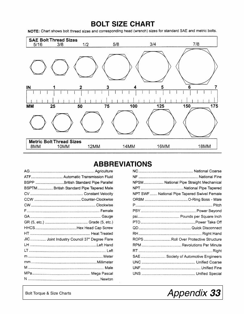
ii Introduction
TO THE DEALER:
Assembly and proper installation of this product is the responsibility of the Frontier dealer. Read manualinstructions and safety rules. Make sure all items on the Dealer’s Pre-Delivery and Delivery Check Lists in theOwner’s/Operator’s Manual are completed before releasing equipment to the owner.
The dealer must complete the Warranty Registration located on the Frontier website.
TO THE OWNER:
Read this manual before operating your Frontier equipment. The information presented will prepare you to do abetter and safer job. Keep this manual handy for ready reference. Require all operators to read this manual care-fully and become acquainted with all the adjustment and operating procedures before attempting to operate.Replacement manuals can be obtained from your Frontier dealer.
The equipment you have purchased has been carefully engineered and manufactured to provide dependable andsatisfactory use. Like all mechanical products, it will require cleaning and upkeep. Lubricate the unit as specified.Observe all safety information in this manual and safety decals on the equipment.
For service, your authorized Frontier dealer has trained mechanics, genuine Frontier service parts, and the neces-sary tools and equipment to handle all your needs.
Use only genuine Frontier service parts. Substitute parts will void the warranty and may not meet standardsrequired for safe and satisfactory operation. Record the model number and serial number of your equipment in thespaces provided:
Model:____________________________________ Date of Purchase:_________________
Serial Number: (see Safety Decal section for location)___________________________________
Provide this information to your dealer to obtain correct repair parts.
Throughout this manual, the term IMPORTANT is used to indicate that failure to observe can cause damage toequipment. The terms CAUTION, WARNING and DANGER are used in conjunction with the Safety-Alert Symbol,(a triangle with an exclamation mark), to indicate the degree of hazard for items of personal safety.
This Safety-Alert Symbol indicates a hazard and means ATTENTION!BECOME ALERT! YOUR SAFETY IS INVOLVED!
Indicates an imminently hazardous situation that, if not avoided, will result in death orserious injury.
Indicates a potentially hazardous situation that, if not avoided, could result in deathor serious injury, and includes hazards that are exposed when guards are removed.
Indicates a potentially hazardous situation that, if not avoided, may result in minor ormoderate injury.
Indicates that failure to observe can cause damage to equipment.
Indicates helpful information.
WARNING
CAUTION
IMPORTANTNOTE
DANGER
BOLT SIZE CHART
ABBREVIATIONS
Bolt Torque & Size Charts Appendix 33

O W N E R ’ S / O P E R A T O R ’ S M A N U A L
ROOT GRAPPLELOADER
ATTACHMENTSAV20
5WS105006 5/2008
PART NO.
5WS105006