
ROOF FRAMING - Habitat for Humanity · · efficient use of fascia is critical!!!! · Use your best...
18
ROOF FRAMING TRUSS LAYOUT………………….………………………..………….51 INSTALLING TRUSSES…….…………………………..…………..51 FRIEZE BOARDS……….……………….………………..…..….….53 HURRICANE CLIPS……………..…………………………………..54 OSB JACKS……………………………………………………………..54 DRYWALL BLOCKING……………………………………………….55 OUTRIGGERS…………………...………...………………………….55 CUTTING TRUSS TAILS.……………………………………...…..56 FASCIA & SHINGLE MOLDING…………………………….....…56 ROOF GUARDS………………………………………………………..57 ROOF DECKING………………………………………….....……….58 KNEE BRACES & GABLE TIES……………………………….…...59 SHEAR WALL/TRUSS CONNECTIONS………………………...60 VALLEY TRUSSES………………………………………..……...….60 AIR HANDLER PLATFORM………………………………………...61 STUCCO STOP..……………………..……………………..………...62 ENCLOSING AN ACTUAL BEAM……….…………………..…….62 FALSE BOX BEAM…………………………………………………….62 ATTIC ACCESS……………………………..………..………...…....63 PLUMB & ANCHOR INTERIOR WALLS……..…………….…..64 TRUSS CLIPS…………………...…………..………………..…..….64 STRAP & SHEER INSPECTION CHECKLIST…………….……65 48
Transcript of ROOF FRAMING - Habitat for Humanity · · efficient use of fascia is critical!!!! · Use your best...

ROOF FRAMING TRUSS LAYOUT………………….………………………..………….51 INSTALLING TRUSSES…….…………………………..…………..51 FRIEZE BOARDS……….……………….………………..…..….….53 HURRICANE CLIPS……………..…………………………………..54 OSB JACKS……………………………………………………………..54 DRYWALL BLOCKING……………………………………………….55 OUTRIGGERS…………………...………...………………………….55 CUTTING TRUSS TAILS.……………………………………...…..56 FASCIA & SHINGLE MOLDING…………………………….....…56 ROOF GUARDS………………………………………………………..57 ROOF DECKING………………………………………….....……….58 KNEE BRACES & GABLE TIES……………………………….…...59 SHEAR WALL/TRUSS CONNECTIONS………………………...60 VALLEY TRUSSES………………………………………..……...….60 AIR HANDLER PLATFORM………………………………………...61 STUCCO STOP..……………………..……………………..………...62 ENCLOSING AN ACTUAL BEAM……….…………………..…….62 FALSE BOX BEAM…………………………………………………….62 ATTIC ACCESS……………………………..………..………...…....63 PLUMB & ANCHOR INTERIOR WALLS……..…………….…..64 TRUSS CLIPS…………………...…………..………………..…..….64 STRAP & SHEER INSPECTION CHECKLIST…………….……65
48

SAFETY TALK
RO
OF F
RA
MIN
G:
Safe
ty T
alk
49
Basic Construction Safety
Ladders
Lifting and Carrying
· #1: Drink plenty of water and watch for dehydration! · When you are tired - Rest! · Know where the First Aid Kit is - if you are hurt, see your House Leader or Site Host
immediately. Our Accident Procedure is in the Site Host Book, please follow it. · Fill out an Incident Report any time the First Aid Kit is opened. · Keep a name tag on at all times. · Use Common Sense! Keep an eye on your own safety and the safety of others. · Concentrate -- especially if you are on a ladder or the roof. · Watch for trip hazards wherever you are going. · Help keep the site safe by picking up and moving things that are in the way. · If you see something unsafe tell your House Leader or a Staff Member. · Hardhats are required to be worn at all times through the completion of drywall lids.
· Bend your knees and lift with your legs not your back. · If something is too heavy, get help - don’t hesitate to ask! · Make sure you can see over what you are carrying. · When carrying something longer than 8 feet have a person on each end.
· At the beginning of each day inspect all ladders for any structural defects that would make them unsafe. If any defects are found, mark the ladder(s) and set it aside for the Site Supervisor’s disposition.
· Use the right size ladder and place it on a solid footing · Never lean an A-frame ladder against anything, always use it fully opened. · Never stand on the top step or back side of a ladder. · Don’t stretch out too far – take the time to move the ladder with your work! · Get someone to steady your ladder if needed. · Only one person on a ladder at a time. · The 4 to 1 rule
For every 4 feet of height, move extension ladders one foot away from the wall.
Power Tools
· Make sure you know how to use a power tool and don’t disable safety features. · Wear safety glasses when using power saws and other power tools that create flying de-
bris. · Take off gloves when working with saws. · Watch fingers near moving parts and tie back long hair. · Use a push stick when using the table saw. · Watch the power cord when cutting and don’t carry a power tool by its cord. · Get help when cutting long pieces of material. · Secure all loose clothing.

RO
OF F
RA
MIN
G:
Overv
iew
50
Key things to remember Truss placement: · Set on correct side of marks. · Gable trusses hang over exterior walls ½” (flush with the OSB). · Temporary truss bracing installed after every fifth truss. · Square cut truss tails. · Trim truss tails and outriggers to length shown in plans. · Miter joint fascia breaks. · Install shingle mold rough side out. · Install 1”x4” mending plates at underside of fascia breaks. · Verify all items on Strap & Brace Checklist are completed.
Efficient material usage FASCIA: · EFFICIENT USE OF FASCIA IS CRITICAL!!!! · Use your best pieces on the front of the house. · For shorter sections use scrap cut off pieces whenever possible before cutting full 16’ ma-
terial.
SHEATHING (OSB & PLYWOOD): · OSB is used vertically on walls, horizontally on roofs, and silver side always faces the House attic. · Use scrap strips of OSB for soffits and beam construction · Paint the good side of plywood · Cut sheets for House overhang.
BLOCKING: · NEVER cut up stud materials. · Cut up scrap, and warped material for blocking before using good material, and make all remaining cuts from the 16’ lineal 2x4 or 2x6.
Basic Construction Safety
· Never walk backwards on roof. · Pay attention to where you are and be extra careful near the edge. · Don’t lay tools down on the roof-they can slide off and injure people below. · Always let people know if you are behind them. · Watch out for the back swing on hammers! · Always keep roof debris free. · Carefully check below before dropping scrap off of the roof.

RO
OF F
RA
MIN
G:
Tru
ss L
ayout,
Insta
llin
g T
russes
Proper selection of volunteers to work on this job is critical. Make certain the people set-ting the trusses are comfortable with their role in the process. Have them work the side walls off of ladders. One person working the top of the trusses is designated to give all instruc-tions. THIS IS THE TIME TO STRESS SAFETY. Hardhats are required for everyone on site. Turn off the generator to allow easier com-munication.
Verify that the truss layout has been marked on the top plate per the truss layout sheet. If not, see preceding truss layout sec-tion.
Before installing the metal vents on the gable end trusses, frame the opening with stucco stop, as you would the exterior doors. Wrap the opening with flashing. Then use two thicknesses of OSB (instead of a 2x) and be sure that the OSB strips are no wider than the vent flange. Be sure that the vents have been
51
PREPARING & INSTALLING TRUSSES
pre-painted the body color. The number of vents and gable trusses varies by model. Use 6d or 8d galva-nized nails to install the vents.
Mark and cut the gable trusses before they are lifted. Starting at the peak, mark 1 1/2" wide spaces @ 48” o.c. through the double top chord on-ly. You cannot cut the mending plates, so if one of the spaces falls over a plate it will have to be moved up the truss to clear the plate.
Once the slots for the outriggers have been marked and verified cut them out, being careful not to over-cut into the top chord of the truss.
Install Guidepost(s) at one gable end to keep trusses plumb (perpendicular to the ground). They should be 1/3 of the way in from each side. A guidepost is two 16’ 2x6’s nailed at right angles to each other. Make sure that the guidepost is nailed with 10d nails to the wall framing (plates and studs), not just through OSB.
TRUSS LAYOUT
pattern until you get to the bastard location. If needed, repeat this procedure from the other end of the wall.
For a flat roof, the space between the first truss and the second truss should always be 21 3/4”. All other non-bastard spaces should be 22 1/2” (24” O.C.).
Starting from the beginning end, transfer all markings to the other side of the house and to any interior bearing walls.
Prior to installing the trusses, re-check the corners of the building to ensure that the walls are plumb and straight. DO NOT REMOVE interior wall braces until after roof decking is completed.
The layout and installation of trusses is the same for both standard and flat roof elevations, except for the first and last trusses.
See the truss calcs provided by the truss manufacturer for the particular truss layout for your house. Note the location of any “bastard trusses”. Bastard trusses are any trusses that are spaced other than 24” apart.
Always use a 100’ tape to do truss layout.
For a gable roof, start your layout at the op-posite end from any bastard spacing. Remem-ber that the gable truss sits flush with the OSB, so your first mark is 1” in from the outside edge of the 2x. Every 24” along the wall from the first mark make a mark, and then cut back 1 1/2” and make a second mark. Continue this
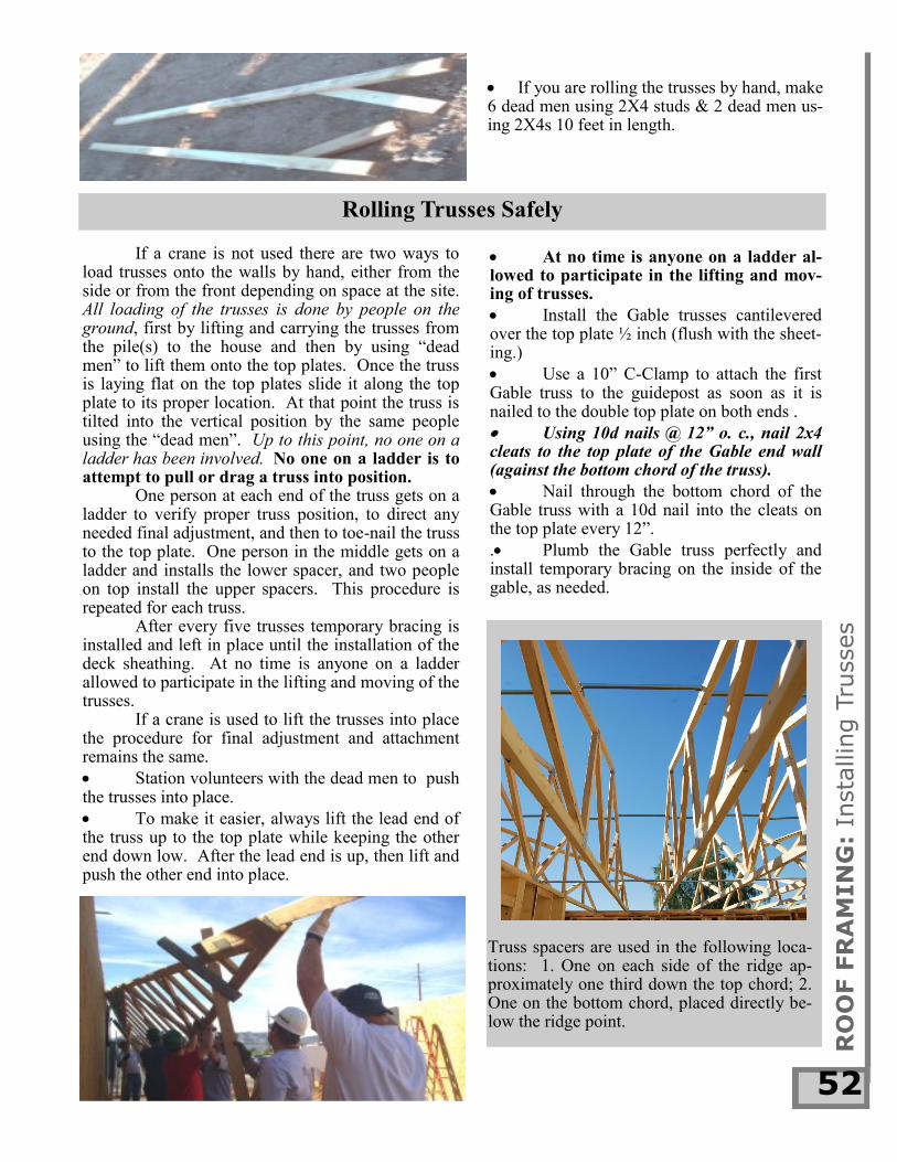
If you are rolling the trusses by hand, make 6 dead men using 2X4 studs & 2 dead men us-ing 2X4s 10 feet in length.
RO
OF F
RA
MIN
G:
Insta
llin
g T
russes
52
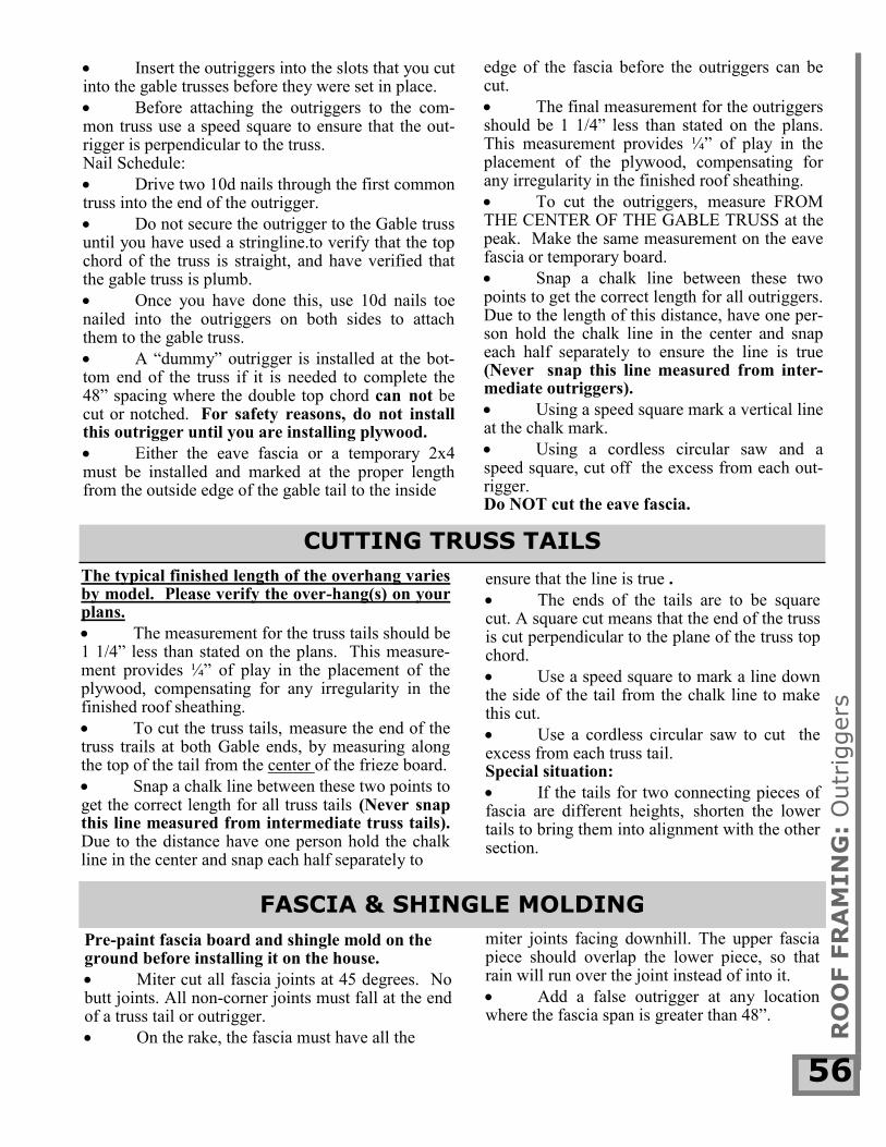
At no time is anyone on a ladder al-lowed to participate in the lifting and mov-ing of trusses.
Install the Gable trusses cantilevered over the top plate ½ inch (flush with the sheet-ing.)
Use a 10” C-Clamp to attach the first Gable truss to the guidepost as soon as it is nailed to the double top plate on both ends .
Using 10d nails @ 12” o. c., nail 2x4 cleats to the top plate of the Gable end wall (against the bottom chord of the truss).
Nail through the bottom chord of the Gable truss with a 10d nail into the cleats on the top plate every 12”.
. Plumb the Gable truss perfectly and install temporary bracing on the inside of the gable, as needed.
Truss spacers are used in the following loca-tions: 1. One on each side of the ridge ap-proximately one third down the top chord; 2. One on the bottom chord, placed directly be-low the ridge point.
If a crane is not used there are two ways to load trusses onto the walls by hand, either from the side or from the front depending on space at the site. All loading of the trusses is done by people on the ground, first by lifting and carrying the trusses from the pile(s) to the house and then by using “dead men” to lift them onto the top plates. Once the truss is laying flat on the top plates slide it along the top plate to its proper location. At that point the truss is tilted into the vertical position by the same people using the “dead men”. Up to this point, no one on a ladder has been involved. No one on a ladder is to attempt to pull or drag a truss into position.
One person at each end of the truss gets on a ladder to verify proper truss position, to direct any needed final adjustment, and then to toe-nail the truss to the top plate. One person in the middle gets on a ladder and installs the lower spacer, and two people on top install the upper spacers. This procedure is repeated for each truss.
After every five trusses temporary bracing is installed and left in place until the installation of the deck sheathing. At no time is anyone on a ladder allowed to participate in the lifting and moving of the trusses.
If a crane is used to lift the trusses into place the procedure for final adjustment and attachment remains the same.
Station volunteers with the dead men to push the trusses into place.
To make it easier, always lift the lead end of the truss up to the top plate while keeping the other end down low. After the lead end is up, then lift and push the other end into place.
Rolling Trusses Safely

RO
OF F
RA
MIN
G:
Fri
eze B
oard
s
53
Continue this bracing pattern on both sides of the trusses as groups of trusses are installed.
The bracing will be removed as the decking is installed to allow truss alignment with the OSB.
FRIEZE BOARDS
Nail Schedule: Two 10d nails through the truss into the frieze board on the accessible end and one toe-nailed from the top down through the truss into the frieze board on the other end.
We use non-vented frieze boards made from 2x4 lineal lumber. The standard length is 22 3/8”, with “bastard” spacings cut to fit. After a group of trusses has been in-stalled, begin putting the frieze boards be-tween the trusses in the following manner: The inside bottom edge of the frieze board lines up with the outside edge of the OSB sheathing.
The frieze board is placed at an angle so that the top side is at the same angle as the top chord of the trusses. It sits between the truss es and flush with the top of the top chord.
trusses are in the correct location. From the ground, look for anything crooked, bowed or off-center as viewed from the side of the trusses.
Nail temporary 16 ft. diagonal bracing from the ridge of the gable truss to just above where the frieze boards are installed at the 5th truss. The next brace is reversed, resulting in a V- shaped pattern.
If your house model has shear boxes between trusses above a shear wall, install them between the appropriate trusses while you are rolling trusses. This is much easier now than doing it later.
Install the remaining trusses by toe nailing them to the double top plate on both sides at both ends with 10d nails.
Instruct the volunteers to install the spacers perpendicular to the trusses to ensure proper spacing between trusses. Use teco nails to secure both ends. Make sure that the trusses are pushed tightly together before nailing off the spacers. If you don’t, the trusses will be too far apart.
Use gloves to protect your hands from sharp edges.
After the Gable truss and next 4 trusses have been installed, stop and verify that all

RO
OF F
RA
MIN
G:
Stu
cco S
top
54
HURRICANE CLIPS
Once the first four common trusses have been rolled and the temporary bracing is in place, have a couple of people prepare and install the temporary OSB jacks (triangular brackets) for the piles of OSB that the crane will be loading once the trusses are all rolled. Working from ladders, install the first piece of OSB in the bottom row. The edges should be centered on the gable truss, the frieze boards, and the fourth common truss. Nail the OSB in place at the four corners and at each intervening truss on the bottom. The two OSB jacks (if not pre-made) should be made of a 2x4 42” long and a 2x4 14” long joined at a right angle with a third 2x4 of the proper length forming the hypotenuse of the triangle. Sheath one side of the jack wi th OSB, and it is ready to install above the first and third common trusses over the sheet of OSB. Make sure that the jacks don’t extend beyond the sheet of OSB where they would be in the way of the next row. Use 10d nails to install the jacks to the trusses. Now repeat this process on the other side of the roof. As soon as all of the trusses are rolled (while the crane is putting 1/4 of the OSB on each of the already installed jacks) install jacks on the two remaining corners of the roof. This must be done quickly so that the crane can also load them (1/4 of the OSB on each jack) before it leaves.
As soon as the first few trusses are braced, volunteers can begin to install the H2.5 clips.
Nail Schedule: As many Teco nails as there are holes in the H2.5.
Install clips only at the ends of trusses for two-point bearing situations. They do NOT get in-stalled over non-load bearing walls, and trusses must NOT contact any non-bearing walls.
H2.5s are to be placed at all bearing loca-tions for multi-point bearing situations, as soon as the trusses are set. The trusses must make solid contact with all bearing walls, use shims if needed, to ensure contact.
OSB JACKS

OUTRIGGERS
DRYWALL BLOCKING
Drywall blocking is necessary in both the verti-cal and horizontal directions. There are four types of ceiling blocking: 1. The combined stucco wrap/drywall block occurs only along the bottom chord of an exposed gable truss that does not require a soffit. (See drawing.) It is easiest to nail the two 2x4’s together while they are on the ground and then install them as a unit. Use a 2x6 if the bottom chord is horizontal (as in floor trusses) not vertical.
Nail Schedule: one 10d every 12”
Ladder blocking is used only where soffits and wrapped beams are hung from the trusses, and also supports the drywall at those locations. Blocks are spaced 24” O.C. 3. Scabbed on blocking is used where the bottom chord of the truss does not
quite stick out far enough from the wall to be used for nailing.
4. Lineal blocking is the stand-ard method that we want to use whenever possible. This method is easier to use and when done properly uses less material than ladder blocking. It is easier for volunteers to attach drywall because it is continuous.
Lineal blocking is a 2x4 nailed in a modified ladder fashion. It will run parallel to the bottom chord of the truss and will fit in between the two trusses. It will be suspended by 2x4s (27 inches long), which are nailed to the top edge of the bottom chord of the truss and spaced no more than 6’ apart. (This method will allow us to start hanging drywall from either end). Keep the blocking 1-2” from the wall. All trusses have a camber (bow) built into the bottom chord, and the amount of bow increases with the length of the truss. Always use lineal blocking, nev-er attach blocking to top of a wall.
Don’t forget to allow for 1½” for the thickness of the stucco when placing exterior drywall ceiling block-ing for the porches. 5. An easy way to do ceiling blocking in small closets, that also serves to square up and solid-ify the walls, is to cut a piece of OSB to the footprint of the closet and then nail it to the top of the top plates. Doing this eliminates multiple blocks in the corners and allows the lid to be installed without having to worry about where the screws will find purchase.
All of the following projects must be done working from ladders, NOT FROM IN THE TRUSSES. Outriggers are the blocks that at-tach to the first common truss and extend through the gable truss to support fascia (barge rafter) and roof decking. R
OO
F F
RA
MIN
G:
Dry
wall B
lockin
g
55
CUTTING TRUSS TAILS
ensure that the line is true .
The ends of the tails are to be square cut. A square cut means that the end of the truss is cut perpendicular to the plane of the truss top chord.
Use a speed square to mark a line down the side of the tail from the chalk line to make this cut.
Use a cordless circular saw to cut the excess from each truss tail. Special situation:
If the tails for two connecting pieces of fascia are different heights, shorten the lower tails to bring them into alignment with the other section.
The typical finished length of the overhang varies by model. Please verify the over-hang(s) on your plans.
The measurement for the truss tails should be 1 1/4” less than stated on the plans. This measure-ment provides ¼” of play in the placement of the plywood, compensating for any irregularity in the finished roof sheathing.
To cut the truss tails, measure the end of the truss trails at both Gable ends, by measuring along the top of the tail from the center of the frieze board.
Snap a chalk line between these two points to get the correct length for all truss tails (Never snap this line measured from intermediate truss tails). Due to the distance have one person hold the chalk line in the center and snap each half separately to
Insert the outriggers into the slots that you cut into the gable trusses before they were set in place.
Before attaching the outriggers to the com-mon truss use a speed square to ensure that the out-rigger is perpendicular to the truss. Nail Schedule:
Drive two 10d nails through the first common truss into the end of the outrigger.
Do not secure the outrigger to the Gable truss until you have used a stringline.to verify that the top chord of the truss is straight, and have verified that the gable truss is plumb.
Once you have done this, use 10d nails toe nailed into the outriggers on both sides to attach them to the gable truss.
A “dummy” outrigger is installed at the bot-tom end of the truss if it is needed to complete the 48” spacing where the double top chord can not be cut or notched. For safety reasons, do not install this outrigger until you are installing plywood.
Either the eave fascia or a temporary 2x4 must be installed and marked at the proper length from the outside edge of the gable tail to the inside
RO
OF F
RA
MIN
G:
Outr
iggers
56
edge of the fascia before the outriggers can be cut.
The final measurement for the outriggers should be 1 1/4” less than stated on the plans. This measurement provides ¼” of play in the placement of the plywood, compensating for any irregularity in the finished roof sheathing.
To cut the outriggers, measure FROM THE CENTER OF THE GABLE TRUSS at the peak. Make the same measurement on the eave fascia or temporary board.
Snap a chalk line between these two points to get the correct length for all outriggers. Due to the length of this distance, have one per-son hold the chalk line in the center and snap each half separately to ensure the line is true (Never snap this line measured from inter-mediate outriggers).
Using a speed square mark a vertical line at the chalk mark.
Using a cordless circular saw and a speed square, cut off the excess from each out-rigger. Do NOT cut the eave fascia.
FASCIA & SHINGLE MOLDING
Pre-paint fascia board and shingle mold on the ground before installing it on the house.
Miter cut all fascia joints at 45 degrees. No butt joints. All non-corner joints must fall at the end of a truss tail or outrigger.
On the rake, the fascia must have all the
miter joints facing downhill. The upper fascia piece should overlap the lower piece, so that rain will run over the joint instead of into it.
Add a false outrigger at any location where the fascia span is greater than 48”.

into a truss tail may poke through the fascia on the inside.)
Remove all shiners (exposed nails) at this point.
RO
OF F
RA
MIN
G:
Fascia
57
2. The easier way is to join the two sections of the fascia. Cut the reciprocal angle of the rake peak angle (i.e. for a 4/12 slope a 71.5 degree angle [90-18.5=71.5]) at the bottom to create a horizontal joint with the eave fascia. You will also need to bev-el cut the rake to match the angle of the eave (18.5 degrees in this example).
Use a clamp when necessary to pull the fascia tightly into place before nailing.
Nail schedule, 16d galvanized nails: Two (2) nails per 2x4 truss tail. Use three 16d galv. for 2x6 and larger tails.
Install 1”x4” mending plates (MP14) on the bottom side of all fascia joints. Paint to match trim color.
Install 1”x3” shingle molding on out-side of fascia, rough side out, flush with top of plywood.
Miter-cut all shingle mold joints at 45 degrees. No butt joints are allowed as the 1x3 will not be completely covered by the drip edge. Do not have non-corner joints fall di-rectly over fascia joints.
Nail schedule, 6d or 8d galvanized nails: One nail every 24” on center into tail end of trusses or outriggers. (Nails that are not
Special situation:
When a rake fascia comes down into an eave fascia there are two ways to handle the joint. 1. Do not join the two sections of fascia in-stead, run the eave under the rake and shingle the resulting lower roof section.
Roof Guards
All pitched-roof houses that we build will require the installation of roof guards (safety rails). The guards must stay in place until ALL roof work (including painting and tarring protrusions) is com-pleted.
As soon as the trusses have been rolled we will install the frieze boards, fascia, shingle mold and plywood (all of this work is to be done from ladders or scaffolding, NOT the trusses).
ROOF DECKING R
OO
F F
RA
MIN
G:
Roof G
uard
s
58
The overhang is sheathed using 1/2” CCX plywood installed with the better side facing down. Cut to size before installing. The exposed (better) side of the plywood should be painted the color of the house body before installation. The plywood runs from the outer edge of the fascia to the middle of the frieze board (or gable truss on the rake). Do not allow the plywood to overhang the edge of the fas-cia.
A space the width of the diameter of an 8d nail is to be left between all sheets.
Nail schedule; 8d nails-Perimeter, 6” o. c, Field 12” o. c., unless different on your plans.
We use OSB with a radiant barrier for all roof decking (unless spray insulation is being used), and it is installed with the shiny side (radiant barrier) down.
For safety, any volunteers lifting decking to the roof should hand the material up and then head TOWARD the house under the eave and then off to the sides. This eliminates the chance of
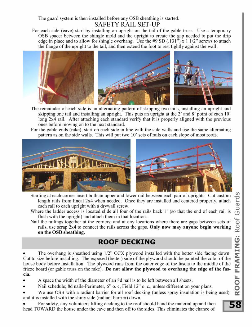
The guard system is then installed before any OSB sheathing is started.
SAFETY RAIL SET-UP For each side (eave) start by installing an upright on the tail of the gable truss. Use a temporary
OSB spacer between the shingle mold and the upright to create the gap needed to put the drip edge in place and to allow for shingle overhang. Use the #9 SD (.131”) x 1 1/2” screws to attach the flange of the upright to the tail, and then extend the foot to rest tightly against the wall .
The remainder of each side is an alternating pattern of skipping two tails, installing an upright and skipping one tail and installing an upright. This puts an upright at the 2’ and 8’ point of each 10’ long 2x4 rail. After attaching each standard verify that it is properly aligned with the previous ones before moving on to the next standard.
For the gable ends (rake), start on each side in line with the side walls and use the same alternating pattern as on the side walls. This will put two 10’ sets of rails on each slope of most roofs.
Starting at each corner insert both an upper and lower rail between each pair of uprights. Cut custom length rails from lineal 2x4 when needed. Once they are installed and centered properly, attach each rail to each upright with a drywall screw.
Where the ladder access is located slide all four of the rails back 1’ (so that the end of each rail is flush with the upright) and attach them in that location.
Nail the railings together at the corners, and at any locations where there are gaps between sets of rails, use scrap 2x4 to connect the rails across the gaps. Only now may anyone begin working on the OSB sheathing.

SAFETY: DO NOT USE A TABLE SAW TO CUT OSB AND PLYWOOD. Use a Skil saw and chalk line when cutting sheet goods. When cutting plywood cut multiple sheets (maximum of 5) at once. Make sure that all edges are properly aligned before making the cuts
RO
OF F
RA
MIN
G:
Roof D
eckin
g
59
TIME SAVER: Use skilled volunteers to cut and set the OSB sheets. Nail only the four cor-ners. When trusses need to be moved to line up with the decking, a stud works well as a lever to move the trusses into place. Move on to the next sheet and use less skilled volunteers to complete the nail pattern.
KNEE BRACES & GABLE TIES
Secure the OSB starting at the frieze board. Butt the OSB tightly against the plywood and nail at 6’ o. c. (including each intermediate truss).
Continue laying the OSB the length of the house. At the far Gable truss, cut the OSB to fit with the center of the top chord.
Snap a line down the center of the top chord of the gable truss. Line up the side edge of the first sheet of OSB on this chalk line and the bottom edge of the OSB on the chalk line snapped earlier on top of the frieze board. There will be a truss every 24” inches O.C. except for “bastard” trusses.
On the next row, the first sheet will be cut to 4 feet in length. Thereafter, the joints will be stag-gered every 4 feet (i.e. repeat the pattern).
The last row of OSB at the ridge CANNOT BE LESS THAN 24” in height.
Before you install the SECOND to the last row of OSB, measure down from the peak of the trusses 24” and mark a line.
From the line, measure down to the top of the previous row of OSB.
If it is less than 48” the SECOND to the last row will need to be cut to fit.
If it is greater than 48” you are able to lay the SECOND to the last row as full height sheets. Re-measure the distance between the top of the second to the last row and the peak of the truss. This must be greater than 24”. Have people on the ground cut the necessary pieces to fit this dimension. Cut multi-ple sheets at once when possible.
The top of the last row should be flush with the peak (no higher) and without any ridge gaps.
the sheet accidentally being dropped onto them from above. Do not back up!
Install ½” OSB roof decking on the roof where the underside is not visible as an exposed surface. A space the width of the diameter of an 8d nail is to be left between all four sides of decking sheets.
Nail schedule; 8d nails-Perimeter, 6” o. c., Field, 12” o. c., unless different on your plans. A space the width of the diameter of an 8d nail is to be left between all four sides of decking sheets.
Nail schedule; 8d nails-Perimeter, 6” o. c., Field, 12” o. c., unless different on your plans.
After your decking is completed, locate where all of your knee braces will be placed. Measure the height of the truss at each location and use that measurement to locate the top block of the knee brace assembly (since the knee brace is supposed to be at 45 degrees the horizontal and vertical measurements will be the same).

VALLEY TRUSSES
RO
OF F
RA
MIN
G:
Knee B
races
60
SHEAR WALL/TRUSS CONNECTIONS Internal shear walls must be attached to the trusses/roof to complete the shear diaphragm. For walls running perpendicular to the trusses this is the time to install the shear boxes if you didn’t do it while rolling the trusses. The shear box connects to the trusses and wall with 10d nails and to the roof deck with 8d nails driven down through the decking.
Interior shear walls running parallel to the trusses are simply connected to the trusses us-ing ladder blocking @ 12” o.c., and blocks on top of the wall between the ladder blocks. The blocks lock the wall to the trusses preventing racking. The trusses transfer the shear forces to the roof completing the diaphragm.
Each gable tie must span at least three truss bays, and if it is over a porch it must extend back past the wall. Be sure to verify drawings, as re-quirements can differ by design and municipality.
Knee Bracing is to be placed along all gable trusses between the points where the distance be-tween the top and bottom truss chords exceeds two feet. Spacing between knee braces is determined from your plans. Make sure that the layout is cen-tered so that there is a knee brace directly below the ridge.
Knee braces are 2x4s run from the joint with the gable tie upward to the roofline at a 45-degree angle. Check the plan details for proper fastening.
The top end of the brace should run to the blocking installed at the roofline.
Attach the bottom of the brace to the gable tie with a clip and strap per your plans.
Nail two 10d nails wherever the brace crosses a truss.
The top of the brace must be nailed with six 10d nails into the top block AND 8d nails at 6” on center through the OSB above into the top of the top block.
Verify location of any lateral bracing required by the truss calcs in the webbing of trusses and that the material is in place. Do Not install the lateral bracing until roof deck-ing is completed.
Nail Schedule: Two 10d nails per truss.
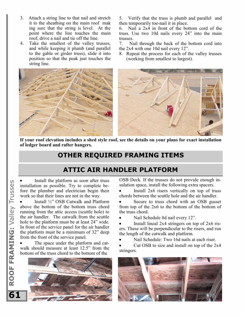
If your house has two ridges running perpendicular you may have a set of Valley Trusses (the small tail-less decreasing size trusses) to install on top of the main roof to complete the intersecting roof. The eas-iest way to determine where these trusses are to be set is as follows: 1. Verify that the main trusses of the intersecting roof are properly installed and sheathed. 2. Install the valley gable or girder truss in their proper location (verify for plumb), and put a nail ver-
tically in the peak.
RO
OF F
RA
MIN
G:
Valley T
russes
61
OTHER REQUIRED FRAMING ITEMS
3. Attach a string line to that nail and stretch it to the sheathing on the main roof mak ing sure that the string is level. At the point where the line touches the main roof, drive a nail and tie off the line.
4. Take the smallest of the valley trusses, and while keeping it plumb (and parallel to the gable or girder truss), slide it into position so that the peak just touches the string line.
If your roof elevation includes a shed style roof, see the details on your plans for exact installation of ledger board and rafter hangers.
5. Verify that the truss is plumb and parallel and then temporarily toe-nail it in place. 6. Nail a 2x4 in front of the bottom cord of the truss. Use two 10d nails every 24” into the main trusses. 7. Nail through the back of the bottom cord into the 2x4 with one 10d nail every 12”. 8. Repeat the process for each of the valley trusses
(working from smallest to largest).
ATTIC AIR HANDLER PLATFORM
Install the platform as soon after truss installation as possible. Try to complete be-fore the plumber and electrician begin their work so that their lines are not in the way.
Install ½” OSB Catwalk and Platform above the bottom of the bottom truss chord running from the attic access (scuttle hole) to the air handler. The catwalk from the scuttle hole to the platform must be at least 24” wide. In front of the service panel for the air handler the platform must be a minimum of 32” deep from the front of the service panel.
The space under the platform and cat-walk should measure at least 12.5” from the bottom of the truss chord to the bottom of the
OSB Deck. If the trusses do not provide enough in-sulation space, install the following extra spacers.
Install 2x6 risers vertically on top of truss chords between the scuttle hole and the air handler.
Secure to truss chord with an OSB gusset from top of the 2x6 to the bottom of the bottom of the truss chord.
Nail Schedule 8d nail every 12”.
Install lineal 2x4 stringers on top of 2x6 ris-ers. These will be perpendicular to the risers, and run the length of the catwalk and platform.
Nail Schedule: Two 16d nails at each riser.
Cut OSB to size and install on top of the 2x4 stringers.

RO
OF F
RA
MIN
G:
Stu
cco S
top,
Box B
eam
s
62
STUCCO STOP
ENCLOSING AN ACTUAL BEAM
4. Raise the OSB assembly and attach it to the outside of the stringer with 8d nails eve-ry 6”. 5. Add 2x4 spacers between the bottom 2x4 and the beam as needed to ensure proper spacing. Do not install the bottom OSB until after the Strap and Shear Inspection. It must be installed before lathing to provide backing for the lath.
1. Cut a 2x4 stringer to length and nail it to the bottom chord of the trusses so that the outside edge of the stringer is the correct distance from the outside edge of the beam. 2. Cut a piece of OSB to the depth of the beam and to the same length as the stringer. 3. Cut another 2x4 the same length as the OSB and
attach the 3 ½” width to the bottom edge of the OSB with 8d nails every 6”.
FALSE BOX BEAM
Check your plans for the finished dimensions of your boxed beams and columns.
Some box beams are completely false, and some enclose an actual beam. The same may be true for columns.
beam. The blocking is located every 24” on center between the outside trusses. Always start from the inside end of the porch. 2. Stringers are the 2x4 supports that run the length of the porch. Install them horizontally with two 10d nails per piece of blocking. 3. Measure the length of the porch and cut OSB to this length. Cut a 2x4 to the same length and attach the 3½” side of the 2x4 to the bottom edge of the OSB with 8d nails every 6”. 4. Raise the pre-nailed OSB and 2x4, and at-tach it to the stringer with 8d nails every 6”. Do this to both sides of the stringers. 5. Add 2x4 blocking between the bottom 2x4s every 24” O.C. to ensure the proper width. Do not install OSB on the bottom of the soffit until after the Strap and Shear Inspection. It must be installed before lathing to provide backing for the lath.
In order to meet Energy Star Requirements, be-fore installing stucco stop the exterior doors must have flashing installed.
The doors are to be flashed like our windows. Take the provided flashing and cut two pieces to a length 3” longer than the height of the door opening, and one piece 12” wider than the opening. Cut a slit in the end of the side pieces to allow it to be folded over onto the 2x frame. Using staples install the side pieces first, with at least 2” on the 2x frame and the rest wrapped over onto the OSB. Center the top piece over the opening, and cut 2” slits in the bottom edge to allow the center section to be folded onto the 2x frame. Attach it over the top of the side pieces
1. The first step is to install the necessary blocking to accept the stringers that hold up the
and tack in place.
Use a table saw to rip lineal 2x4 mate-rial in half resulting in pieces approximately 1 ¾” x 1 ½”.
Safety First: Use a push stick when cutting on the table saw.
Be sure that all stucco stop is installed over the flashing so that the wider (1 3/4”) dimension is parallel to the wall surface, oth-er wise the stucco will not be the correct thick-ness.
Nail Schedule: One 10d nail every 12”.

The bottom chords of the trusses form the bottom piece of the sides of the scuttle hole. The side pieces and end pieces are also connected with gusset plates of OSB located on the OUTSIDE of the opening. The sides and ends of the scuttle hole must be at least 12” high to act as insulation dams if the access is located within the insulated envelope.
INTERIOR FIRE BLOCKING
Bathroom chases (where the bathroom is wider than the 5’ length of the tub) must be fire-blocked with two layers of OSB across the top. Remember to do this before the plumbing top-out so that you don’t have to piece the OSB in around the water lines.
ATTIC ACCESS
Install the scuttle hole (attic access) as soon after truss installation as possible. This keeps all sub-contractors from blocking access to this space. Location of attic access varies per house plan. IF YOU HAVE ANY QUESTIONS, Check with staff for the correct location. THE MINIMUM ROUGH OPENING OF THE SCUTTLE HOLE IS 22½”X31”. Code requires a minimum vertical clearance of 34” above the hole.
RO
OF F
RA
MIN
G:
Att
ic A
ccess
63

RO
OF F
RA
MIN
G:
Anchor
Walls,
Tru
ss C
lips
64
PLUMB & ANCHOR INTERIOR WALLS
Set an 8’ level between the top and bottom plates and adjust the wall until it is plumb in both directions. Do not rest the level against a stud, as it will take on any gaps or warps in the stud. Verify that all walls with cabinets are perfectly perpendicu-lar to the adjoining walls by using a 4 x 8 piece of OSB as an oversized “framing square”.
Secure the end studs of interior walls to ad-joining walls with two 10d nails at every ladder rung, or at 16” o.c. at Cal Corners.
Secure first floor interior wall bottom plates every 24” with powder activated fasteners (Ramset). Check your plans for any areas (shear panels) that require additional anchors.
Second floor plates are anchored every 24”with 2-10d nails. These nails must be into a truss.
Secure the walls with temporary angle brac-ing. Use Stud material, not lineal 2x4s for braces.
Do not remove the temporary bracing before the roof sheeting has been completed. Leaving the temporary bracing in place as long as possible will help keep the house plumb.
Once you are certain that the walls are exact-
ly where they are supposed to be, run a 3” long bead of Liquid Nails along both sides of the bottom plate/slab joint on both sides of every doorway in the house. Be careful to ensure that no Liquid nails extends into the doorway onto the door sill we will re-move once the adhesive is dry.
Please remove the door sills at the beginning of the next work day.
This process will anchor the door framing more securely than anything we have done previously, and will eliminate multiple trip hazards from the site.
TRUSS CLIPS
For wall to Truss Blocking: Secure top plates of interior walls to trusses with HTC clips.
Double check that all interior walls are square and plumb before installing the HTCs.
If trusses are too high for the clips to reach, install a block between the clip and the top plate.
Make sure that the block does not stick out past the wall where sheetrock will be hung.
Do not place the block under the truss itself, as it may interfere with the truss settling. Nail Schedule, Teco nails about 1” up from the bottom of the truss in the slots and in all holes to attach the clip to the wall.
Install clips per your plans.
Standard two point trusses cannot rest on any intermediate walls. If they do, notch the dou-ble top plate as needed to provide clearance.

RO
OF F
RA
MIN
G:
Inspection
65
STRAP & SHEAR INSPECTION CHECKLIST
1. H2.5s at all bearing points on every truss, completely nailed with Teco nails. 2. Sheathing nailed at every 6” on edges and every 12” in field (8d nails). Verify any special
nail patterns on plans. 3. Joint in top plate cannot be within 2’ of joint in double top plate. 4. Knee braces on gable trusses run from top of wall inward to roof. Clip and strap at bottom joint and 6 10d nails at top joint. Knee braces are located 6’ O.C. 5. Bottom cord of Gable truss is nailed to blocking every 12” (one 10d nail). 6. Gable ties minimum three truss bays long at 6’ O.C. (per plans). 7. Lineal bracing, minimum overlap at joints 2’. Use two (10d) nails at each truss. 8. Wall anchors at 4’ O.C. (or per plans) and within 12” on both sides of break in bottom plate on exterior walls. 9. Interior walls anchored with ramset nails at minimum 2’ O.C., and check plans for special (shear locations). 10. HTC clips installed. 11. Front porch columns and soffits are completed. 12. Verify all door and window openings for proper size. 13. Verify all walls and door openings are plumb. 14. Windows Installed. Items not required for inspection, but needed for subcontractors 15. Insulation installed on exterior walls behind tubs. 16. All interior fire blocking installed. 17. Scuttle hole framed in and marked.
Sweep all debris from inside the tubs. This debris removal will help prevent anything from staining the tub surface when the plumbers fill the tub with water for inspection.
CLEAN UP