Rolling/sliding of a particle on a flat wall in a linear shear flow at finite Re
17
Rolling/sliding of a particle on a flat wall in a linear shear flow at finite Re Hyungoo Lee a , Man Yeong Ha b , S. Balachandar a,⇑ a Department of Mechanical and Aerospace Engineering, University of Florida, Gainesville, FL 32611, USA b School of Mechanical Engineering, Pusan National University, Jang Jeon 2-Dong, Geum Jeong Gu, Busan 609-735, Republic of Korea article info Article history: Received 2 September 2010 Received in revised form 17 October 2010 Accepted 17 October 2010 Available online 26 October 2010 Keywords: Drag and lift forces Resuspension of particles Rolling/sliding motion of a particle Direct numerical simulations Immersed boundary method Added-mass and history forces abstract Recently Lee and Balachandar proposed analytically-based expressions for drag and lift coefficients for a spherical particle moving on a flat wall in a linear shear flow at finite Reynolds number. In order to eval- uate the accuracy of these expressions, we have conducted direct numerical simulations of a rolling par- ticle for shear Reynolds number up to 100. We assume that the particle rolls on a horizontal flat wall with a small gap separating the particle from the wall (L = 0.505) and thus avoiding the logarithmic singularity. The influence of the shear Reynolds number and the translational velocity of the particle on the hydro- dynamic forces of the particle was investigated under both transient and the final drag-free and torque- free steady state. It is observed that the quasi-steady drag and lift expressions of Lee and Balachandar provide good approximation for the terminal state of the particle motion ranging from perfect sliding to perfect rolling. With regards to transient particle motion in a wall-bounded shear flow it is observed that the above validated quasi-steady drag and lift forces must be supplemented with appropriate wall- corrected added-mass and history forces in order to accurately predict the time-dependent approach to the terminal steady state. Quantitative comparison with the actual particle motion computed in the numerical simulations shows that the theoretical models quite effective in predicting rolling/sliding motion of a particle in a wall-bounded shear flow at moderate Re. Ó 2010 Elsevier Ltd. All rights reserved. 1. Introduction The rolling or sliding motion of particles, droplets and bubbles on a surface, with or without an ambient flow, occurs in many household, industrial and environmental situations. In order to de- scribe the particle motion in these situations it is important to accurately know the hydrodynamic forces exerted on the particle by the surrounding fluid. The particle motion will then be dictated by a balance between the hydrodynamic forces, gravitational ef- fect, contact friction with the wall and other influences such as electrostatic forces. For a particle moving in close proximity to a wall, the hydrody- namic forces are greatly influenced by the presence of the wall. In the Stokes limit, Goldman et al. (1967a,b) obtained analytical re- sults for the drag force and the hydrodynamic torque on a particle for both the cases of a stationary particle in a wall-bounded linear shear flow and a translating–rotating particle moving parallel to a wall in a quiescent fluid. In particular, for the later case of a moving particle they obtained logarithmically increasing drag force and torque as the gap between the particle and the wall decreases. This lubrication singularity will prevent particle motion when it is in contact with the wall. Hydrodynamic lift force on the particle is due to inertial effect and thus vanishes in the Stokes limit. Krishnan and Leighton (1995) have shown that in the low Reynolds number regime the lift force on a particle rotating and translating parallel to a wall in a linear shear flow can be expressed as superposition of six contribu- tions. The first three are individual contributions from the ambient wall-bounded shear flow, translational motion and the rotational motion of the particle. The other three binary contributions arise from shear–translation, shear–rotation and translation–rotation interactions. There have been experimental verification of low Reynolds number theories (King and Leighton, 1997). In these experiments the rolling motion of a particle on a horizontal flat wall and incip- ient lift-off from the surface are monitored and compared with the theoretical results. Logarithmic singularity in drag and torque are avoided by accounting for the surface roughness of the particle and the flat plate, which provide a non-zero gap between the par- ticle and the wall. With appropriate values of roughness the theo- retical predictions were shown to be in good agreement with the experimental measurements (King and Leighton, 1997). For the general case of a particle translating and rotating in a wall-bounded shear flow, we have different choices for the velocity scale: the shear velocity at the particle center, the translational 0301-9322/$ - see front matter Ó 2010 Elsevier Ltd. All rights reserved. doi:10.1016/j.ijmultiphaseflow.2010.10.005 ⇑ Corresponding author. Tel.: +1 352 392 0961; fax: +1 352 392 7303. E-mail address: bala1s@ufl.edu (S. Balachandar). International Journal of Multiphase Flow 37 (2011) 108–124 Contents lists available at ScienceDirect International Journal of Multiphase Flow journal homepage: www.elsevier.com/locate/ijmulflow
-
Upload
hyungoo-lee -
Category
Documents
-
view
213 -
download
0
Transcript of Rolling/sliding of a particle on a flat wall in a linear shear flow at finite Re

International Journal of Multiphase Flow 37 (2011) 108–124
Contents lists available at ScienceDirect
International Journal of Multiphase Flow
journal homepage: www.elsevier .com/locate / i jmulflow
Rolling/sliding of a particle on a flat wall in a linear shear flow at finite Re
Hyungoo Lee a, Man Yeong Ha b, S. Balachandar a,⇑a Department of Mechanical and Aerospace Engineering, University of Florida, Gainesville, FL 32611, USAb School of Mechanical Engineering, Pusan National University, Jang Jeon 2-Dong, Geum Jeong Gu, Busan 609-735, Republic of Korea
a r t i c l e i n f o a b s t r a c t
Article history:Received 2 September 2010Received in revised form 17 October 2010Accepted 17 October 2010Available online 26 October 2010
Keywords:Drag and lift forcesResuspension of particlesRolling/sliding motion of a particleDirect numerical simulationsImmersed boundary methodAdded-mass and history forces
0301-9322/$ - see front matter � 2010 Elsevier Ltd. Adoi:10.1016/j.ijmultiphaseflow.2010.10.005
⇑ Corresponding author. Tel.: +1 352 392 0961; faxE-mail address: [email protected] (S. Balachandar).
Recently Lee and Balachandar proposed analytically-based expressions for drag and lift coefficients for aspherical particle moving on a flat wall in a linear shear flow at finite Reynolds number. In order to eval-uate the accuracy of these expressions, we have conducted direct numerical simulations of a rolling par-ticle for shear Reynolds number up to 100. We assume that the particle rolls on a horizontal flat wall witha small gap separating the particle from the wall (L = 0.505) and thus avoiding the logarithmic singularity.The influence of the shear Reynolds number and the translational velocity of the particle on the hydro-dynamic forces of the particle was investigated under both transient and the final drag-free and torque-free steady state. It is observed that the quasi-steady drag and lift expressions of Lee and Balachandarprovide good approximation for the terminal state of the particle motion ranging from perfect slidingto perfect rolling. With regards to transient particle motion in a wall-bounded shear flow it is observedthat the above validated quasi-steady drag and lift forces must be supplemented with appropriate wall-corrected added-mass and history forces in order to accurately predict the time-dependent approach tothe terminal steady state. Quantitative comparison with the actual particle motion computed in thenumerical simulations shows that the theoretical models quite effective in predicting rolling/slidingmotion of a particle in a wall-bounded shear flow at moderate Re.
� 2010 Elsevier Ltd. All rights reserved.
1. Introduction
The rolling or sliding motion of particles, droplets and bubbleson a surface, with or without an ambient flow, occurs in manyhousehold, industrial and environmental situations. In order to de-scribe the particle motion in these situations it is important toaccurately know the hydrodynamic forces exerted on the particleby the surrounding fluid. The particle motion will then be dictatedby a balance between the hydrodynamic forces, gravitational ef-fect, contact friction with the wall and other influences such aselectrostatic forces.
For a particle moving in close proximity to a wall, the hydrody-namic forces are greatly influenced by the presence of the wall. Inthe Stokes limit, Goldman et al. (1967a,b) obtained analytical re-sults for the drag force and the hydrodynamic torque on a particlefor both the cases of a stationary particle in a wall-bounded linearshear flow and a translating–rotating particle moving parallel to awall in a quiescent fluid. In particular, for the later case of a movingparticle they obtained logarithmically increasing drag force andtorque as the gap between the particle and the wall decreases. This
ll rights reserved.
: +1 352 392 7303.
lubrication singularity will prevent particle motion when it is incontact with the wall.
Hydrodynamic lift force on the particle is due to inertial effectand thus vanishes in the Stokes limit. Krishnan and Leighton(1995) have shown that in the low Reynolds number regime the liftforce on a particle rotating and translating parallel to a wall in alinear shear flow can be expressed as superposition of six contribu-tions. The first three are individual contributions from the ambientwall-bounded shear flow, translational motion and the rotationalmotion of the particle. The other three binary contributions arisefrom shear–translation, shear–rotation and translation–rotationinteractions.
There have been experimental verification of low Reynoldsnumber theories (King and Leighton, 1997). In these experimentsthe rolling motion of a particle on a horizontal flat wall and incip-ient lift-off from the surface are monitored and compared with thetheoretical results. Logarithmic singularity in drag and torque areavoided by accounting for the surface roughness of the particleand the flat plate, which provide a non-zero gap between the par-ticle and the wall. With appropriate values of roughness the theo-retical predictions were shown to be in good agreement with theexperimental measurements (King and Leighton, 1997).
For the general case of a particle translating and rotating in awall-bounded shear flow, we have different choices for the velocityscale: the shear velocity at the particle center, the translational

du
Ω
G= dy
~
~~
L
~~x
y
~
~mg
~
T~
Ny
~
Fy
~
Fx ,Vp
~
~
Fig. 1. A schematic representation of a spherical rolling particle in a wall-boundedlinear shear flow and nomenclature used in this study.
H. Lee et al. / International Journal of Multiphase Flow 37 (2011) 108–124 109
velocity of the particle, or the surface velocity on the particle due toits rotation. Correspondingly different (shear, translation and rota-tion) particle Reynolds numbers can be defined. The low Reynoldsnumber theory of Krishnan and Leighton (1995) applies when allthese Reynolds numbers are less than unity. It is our interest to ex-tend the theoretical understanding to finite Reynolds numbers, ob-tain accurate expressions for drag and lift forces, and therebyextend our ability to predict rolling and sliding motion of particlesover a wider range of applications.
At finite particle Reynolds number the nonlinearity of the prob-lem can be expected to significantly complicate the role of ambientshear, particle translation and rotation and their interaction. Theresulting dependence of hydrodynamic drag and lift forces on parti-cle shear, translation and rotation Reynolds numbers is likely to bemore complex. Recently Lee and Balachandar (2010) have devel-oped relations for drag and lift forces on a particle that are applica-ble for particle Reynolds numbers up to 100. Their approach was toassume the binary superposition of the low Reynolds number theo-retical analysis of Krishnan and Leighton (1995) to be applicableeven at finite Reynolds numbers. Based on this supposition, theyproposed new drag and lift relations for shear, translation and rota-tion mechanisms and their binary interaction.
The problem of translational particle motion parallel to a flatwall in a quiescent fluid at finite Reynolds number has been consid-ered by Takemura and Magnaudet (2003), Zeng et al. (2005). Theproblem of forces on a stationary particle in a wall-bounded linearshear flow at finite Reynolds number was considered by Zenget al. (2009). In particular, the later work included the limit of par-ticle nearly in contact with the wall. These existing results were uti-lized by Lee and Balachandar (2010), where in addition theindividual mechanism of particle rotation in close proximity to awall, and the binary shear–translation, shear–rotation and transla-tion–rotation mechanisms were considered at finite Reynolds num-ber. Combining all these results they constructed a superpositionthat resulted in composite expressions for drag and lift forces.
The purpose of this paper is to test the drag and lift relationspresented in Lee and Balachandar (2010) and validate their appli-cability over the intended Reynolds number range. In particular,at finite Reynolds numbers the nonlinear effect may not be limitto only quadratic and binary interactions between shear, transla-tion and rotation. Higher order interactions among the differentmechanisms, and in particular the simultaneous interaction of allthree mechanisms may become insignificant. In the general caseof a particle rolling in a wall-bounded shear flow all three mecha-nisms are simultaneously present, and such tertiary interactionswill be considered here for the first time, to thoroughly test thedrag and lift relations. Furthermore, here we will go beyond thesteady state, and consider the free motion of particle in wall-bounded shear flows. Under such unsteady condition, added-massand Basset history forces will become important as well, providedthe particle to ambient fluid density ratio is not large. Here we willuse the wall effect on added-mass (Kharlamov et al., 2007) and his-tory (Yang, 2006) forces and combine them with the quasi-steadyrelations presented in Lee and Balachandar (2010) to predict thefree-rolling motion of a particle on a horizontal flat wall in a linearshear flow (see Fig. 1) and compare the drag and lift expressionswith those obtained from direct numerical simulations.
2. Problem description
We consider a spherical particle of diameter d, rotating at anangular velocity eX about the z-axis and translating at a velocityeV p parallel to a horizontal flat wall (see Fig. 1). If the moving par-ticle is in contact with the wall, a logarithmic singularity arises(Goldman et al., 1967a,b). To prevent that, we locate the particle
center at a distance eL ¼ 0:505d from the wall, thus allowing a nar-row gap between the particle and the wall. The far-field ambientflow surrounding the particle is a linear shear flow, whose onlynon-zero velocity component is along the x-axis parallel to thewall. The shear flow can be written as ~uð~yÞ ¼ eGð~yþ eLÞ, where eGis the dimensional shear-rate of the ambient flow ðd~u=d~yÞ.
We choose the particle diameter d to be the length scale. In thisproblem, we can consider at least three independent velocityscales: (i) the local shear flow velocity at the center of the particleðeGeLÞ, (ii) the translational velocity of the particle ðeV pÞ along the x-axis, and (iii) the velocity difference across a particle diameter dueto rotation about the z-axis ðeXÞ. For the general discussion andmathematical formulation we will call the velocity scale to be eVand leave it unspecified. The non-dimensional time and pressureare defined as t ¼ ~teV=d and p ¼ ~p=ðqeV 2Þ. The dimensionless gov-erning equations in a frame translating with the particle reducesto:
r � u ¼ 0;@u@t þ u � ru ¼ �rpþ 1
Rer2u� dVp
dt ex þ f;ð1Þ
where the Reynolds number is defined as Re ¼ eV d=m. The term�dVp/dt on the right hand side takes into account the non-inertial referenceframe translating with the particle ðVp ¼ eV p=eV Þ. A force field f is ap-plied within the volume occupied by the particle, which in conjunc-tion with the immersed boundary technique being employed hereenforces the correct velocity boundary condition on the surface ofthe particle. We can also define particle Reynolds numbers basedon shear, translation, rotation and relative velocity as:
ðShearÞ Res ¼ jeGjeLd=m ¼ 2jGjLRe � jGjRe;
ðTranslationalÞ Ret ¼ jeV pjd=m ¼ jVpjRe;
ðRotationalÞ ReX ¼ jeXjd2=m ¼ 2jXjRe;
ðRelativeÞ Rer ¼ jeGeL � eV pjd=m ¼ j2GL� VpjRe � jG� VP jRe:ð2Þ
Here we have used the fact that for a particle nearly touching androlling on a flat surface L � 1/2. Here G ¼ eGd=ð2eV Þ and another use-ful dimensionless parameter that measures the relative strength ofparticle rotation is, a ¼ �eXd=ð2eV pÞ ¼ �X=Vp. We define a particleto be ‘‘Forward moving’’ if it translates in the direction of shear flow(Vp > 0). The particle will be ‘‘Backward moving’’ if it translatesagainst the shear flow (Vp < 0). Also, if particle rotation is consistentwith its translation (VpX 6 0) then the particle will be defined to be‘‘Forward rolling’’. If not (i.e. if VpX P 0) the particle is said to be‘‘Backward rolling’’ as in back-spinning motion. Such back-spin mo-tion has been observed in experiments (Stewart et al., 2010).
Here we will consider a particle in free motion in a wall-bounded linear shear flow. However, the particle motion will be re-stricted parallel to the wall and thus we use a frame of referencethat translates parallel to the wall attached to the particle and inthis frame the particle only rotates and the wall translates, but

110 H. Lee et al. / International Journal of Multiphase Flow 37 (2011) 108–124
remains at the same distance from the particle. We employ an im-mersed boundary technique in order to impose the appropriatevelocity boundary conditions on the surface of the rotating spher-ical particle, while working with a fixed Cartesian grid (Uhlmann,2005). A mixed uniform and non-uniform Cartesian grid systemis employed in the simulations. In the immersed boundary regionthat embeds the sphere, a uniform Cartesian mesh of equal resolu-tion along all three directions is used (Dx = Dy = Dz). This high-res-olution region extends over [�1,1] � [�0.505,1] � [�1,1] alongthe streamwise, wall-normal and spanwise directions, with theparticle center being at the origin in the frame attached to the par-ticle. Outside this region of uniform grid a non-uniform grid with ageometric grid-stretching is employed. The overall grid resolutionused in the simulations is 371 � 129 � 151 points and the compu-tational domain employed extends over [�25,25] � [�0.505,8] �[�7,7] along the streamwise, wall-normal and spanwise direc-tions. The choice of the domain size and grid resolution are consis-tent with those used in Zeng et al. (2009), Lee and Balachandar(2010), who established their adequacy.
Here we have used the immersed boundary method of Uhlmann(2005) to enforce the no-slip condition on the particle. Subtle var-iation in its implementation is however required in order to obtainaccurate results of the hydrodynamic forces, especially in the con-text where the particle is very close to the wall. For example, theuse of a single-layer of Lagrangian grid points (where the force fieldf is applied) which only covers the particle-fluid interface givesslight discrepancy in the computed hydrodynamic forces com-pared to the spectral element results of Zeng et al. (2009).
Here the accuracy of the immersed boundary technique is im-proved using multiple layers of Lagrangian forcing points.Although it adds to computational cost, this approach providesthe needed accuracy. We adopt 20 spherical layers covering the en-tire particle in conjunction with a grid resolution of 40 pointsresolving one particle diameter in order to obtain accurate hydro-dynamic forces and moments. The resulting number of Lagrangianforcing points used in the implementation of the immersed bound-ary technique is 36,077.
A second-order accurate central difference scheme is used forthe spatial discretization of the governing equations on a non-stag-gered Cartesian grid system. A fractional step method is used forthe time advancement. In the advection-diffusion step, the nonlin-ear terms are treated explicitly using second-order Adams-Bash-forth scheme and the diffusion terms are treated implicitly withthe Crank–Nicolson scheme. The final divergence-free velocity isobtained at each time step with a pressure correction step. Pres-sure correction requires the solution of the pressure Poisson equa-tion. The details of the numerical methodology and the immersedboundary technique have been discussed in Lee and Balachandar(2010) and will not be repeated here. In particular, in the contextof the small gap between the particle and the wall it is importantto firmly establish the adequacy of the present approach and theresolution employed. Detail tests were performed and the resultswere compared against those from body-fitted higher-order accu-rate spectral element methodology, which have been reported inLee and Balachandar (2010).
The time-dependent motion of a rigid spherical particle is gov-erned by Newtonian dynamics for linear and angular momentum,which for the present problem can be written in dimensional termsas,
mpdeV p
d~t¼ eF x; eNy ¼ mp~g � eF y and Ip
deXd~t¼ eT ; ð3Þ
where mp = pqpd3/6 and Ip = mpd2/6 are the mass and moment ofinertia of the particle, ~g is acceleration due to gravity. Here it isassumed that the gravitational forces directs normal to the wall.
The hydrodynamic forces on the particle along the x and y directionare eF x and eF y, and eT is the hydrodynamic torque about the particlecenter of mass. Here it is assumed that the particle is sufficientlyheavy that it stays in close contact with the wall and as a resultthe normal force ~Ny exerted by the wall on the particle balancesthe weight and the lift force. Also, in order to keep the problem sim-ple we ignore the contact frictional force between the particle andthe wall. The purpose of the paper is to validate the hydrodynamicdrag and lift forces and the present simplified model will be suffi-cient for this purpose.
In the direct numerical simulations, the force field f is inte-grated around the particle to obtain the drag and lift forces andthe net torque on the particle. The drag force and torque are usedin the equations of particle motion (3) to compute the streamwiseand angular accelerations of the particle. The streamwise accelera-tion is used in the governing Eq. (1). The integrated streamwisevelocity and angular velocity of the particle are then used in com-puting the far-field, wall and particle surface velocity boundaryconditions in the frame of reference attached to the particle.
3. Theoretical model of drag and lift forces
We also use equation (3) in conjunction with the theoreticalmodels of drag and lift forces in order to predict the particle’s tran-sient motion. Here we consider the problem of unsteady particlemotion along the streamwise direction in a steady linear shearflow. For the streamwise component of particle motion a modifiedBasset–Boussinesq–Oseen (BBO) equation, adapted for finiteReynolds number, will be used. The temporal and convective accel-erations of the ambient shear flow are identically zero. The x-com-ponent of the hydrodynamic force on the particle can be written as,
eF x ¼p8qf d
2 eV 2CD; ~w � CkMmfdeV p
d~t� 3pld
Z t
�1Kkð~t � ~sÞd
eV p
d~sd~s: ð4Þ
Here the first term on the right represents the quasi-steady compo-nent of drag that depends on only the instantaneous relative veloc-ity between the particle and the ambient flow. In the limit of anunbounded uniform ambient flow the drag coefficient can be writ-ten as CD = (24/Re) (1 + 0.15Re0.687), and CD; ~w in (4) will account forthe added influences of ambient shear, presence of a nearby flatwall and particle rotation in a systematic way.
The next two terms account for the unsteady effects, which inthe present problem arise from the time-dependent motion ofthe particle. The second term on the right is the added-mass force,while the last term on the right is the Basset history force. In (4) mf
is the mass of fluid displaced by the particle, CkM is the added-masscoefficient and Kk is the drag history kernel. In an unbounded uni-form flow the added-mass and history forces are well establishedin the low Reynolds number limit. Their extension to finiteReynolds numbers is also reasonably well understood (Riveroet al., 1991; Mei and Adrian, 1992; Kim et al., 1998; Wakaba andBalachandar, 2005). Here in addition the effect of the wall on whichthe particle moves must also be taken into account.
The corresponding equation for the wall-normal y-componentof force can be expressed as
eF y ¼p8qf d
2 eV 2CL; ~w � 3pldZ t
�1KLð~t � ~sÞd
eV p
d~sd~s: ð5Þ
Here again the first term on the right corresponds to quasi-steadylift force. The second term on the right is the history contributionto the lift force due to streamwise acceleration of the particles,where KL is the lift history kernel. In the case of a spherical particleundergoing time-dependent unidirectional motion in a steady un-bounded uniform ambient flow the added-mass and history forcesare aligned with the direction of particle acceleration. In other

H. Lee et al. / International Journal of Multiphase Flow 37 (2011) 108–124 111
words, there will be only added-mass and history contributions to thedrag force, and owing to symmetry, there will be neither steady norunsteady contribution to lift force. In the present problem thesymmetry is broken in two ways. The ambient shear flow breaksaxisymmetry and the unsteady contribution to lift force arising fromthis asymmetry has been addressed by Legendre and Magnaudet(1998), Asmolov and McLaughlin (1999), Wakaba and Balachandar(2005). Even in the absence of ambient shear flow, the presence ofthe wall breaks axisymmetry and will give rise to an unsteadycontribution to the lift force.
We draw attention to two additional points. First, the quasi-steady forces are traditionally non-dimensionalized in terms of rel-ative velocity. However, in (4) and (5) the scaling is in terms of eVand the drag and lift coefficients are defined accordingly. Second,the rotational motion of the particle is coupled to its translationalmotion. The angular velocity of the particle will contribute to dragand lift forces, which will be accounted in the drag and lift coeffi-cients to be presented below. Similarly, the translational motion ofthe particle and the ambient shear will contribute to a net z-torqueon the particle. This torque will in turn determine the rotationalmotion of the particle. Lee and Balachandar (2010) presented mo-ment coefficient for a particle rotating near a flat wall in a quies-cent fluid. Unfortunately similar information on momentcoefficient for shear and translation effects are not available. Herein our modeling we will attempt to partially decouple the transla-tional and rotational motion of the particle. Also, the followingexpressions are used to define the drag and lift coefficients;
CD ¼eF x
p8 qf
eV 2d2 ; CL ¼eF y
p8 qf
eV 2d2 : ð6Þ
We want to point out that the separation of the total force intoindividual contributions as written in (4) and (5) is for modelingconvenience. Only the total force is realized in the numerical simu-lations. The separation into individual contributions is unique onlywhen the physics of the different terms is precisely defined. Here,we interpret the quasi-steady force as the force that would be exp-erted on the particle if the instantaneous ambient flow around theparticle were to remain unchanged over time as a steady flow. Thusthe added-mass and history forces entirely account for the effect ofunsteadiness. Here again the added-mass force is precisely definedas the force exerted on the particle if the ambient unsteady flow (inthe particle frame of reference) were to be inviscid. Thus the historyforce accounts for all viscous effects of unsteadiness. Such decom-position naturally occurs in the zero Reynolds number limit as inthe Basset–Boussinesq–Oseen equation of particle motion and hasbeen extended to finite Re as shown above.
3.1. Quasi-steady drag
In the low Reynolds number limit, the drag force on the particlecan be determined by a simple linear superposition of the threebasic mechanisms (i.e. Shear, Translation and Rotation). Lee andBalachandar (2010) reported that for accurate prediction of dragadditional binary-coupling term are required at finite Reynoldsnumbers. They proposed an appropriate expression for drag thatis valid over the range Re 6 100,�1 6 Vp 6 1 and �1 6X 6 1.Here, we briefly summarize their drag superposition (7) as:
CD; ~w ¼ CDs;wGjGj|fflfflfflfflfflffl{zfflfflfflfflfflffl}S
�CDt; ~wVpjVpj|fflfflfflfflfflfflfflfflfflffl{zfflfflfflfflfflfflfflfflfflffl}T
�CDX;~wXjXj|fflfflfflfflfflfflfflfflffl{zfflfflfflfflfflfflfflfflffl}R
�jGjVpgstðRes;Vp=GÞ|fflfflfflfflfflfflfflfflfflfflfflfflfflfflfflfflfflffl{zfflfflfflfflfflfflfflfflfflfflfflfflfflfflfflfflfflffl}ST
�jGjXgsXðRes;X=GÞ|fflfflfflfflfflfflfflfflfflfflfflfflfflfflfflfflffl{zfflfflfflfflfflfflfflfflfflfflfflfflfflfflfflfflffl}SR
�jVpjXgtXðRet;X=VpÞ|fflfflfflfflfflfflfflfflfflfflfflfflfflfflfflfflfflfflffl{zfflfflfflfflfflfflfflfflfflfflfflfflfflfflfflfflfflfflffl}TR
: ð7Þ
The above drag superposition has six combinations of which threeare from individual mechanisms (S; Shear flow, T; Translation mo-tion and R; Rotation motion) and the other three are from binary-coupling (ST; Shear+Translation, SR; Shear+Rotation, TR; Transla-tion+Rotation). Note that the shear-induced drag CDs,w remainsbounded even in the limit of particle in contact with the flat surface.In contrast, due to lubrication singularity, the translation and rota-tion-induced drag (i.e., CDt; ~w and CDX; ~w) will logarithmically divergeas the particle approaches the surface. Here and henceforth, thesubscript ’w’ denotes values that are applicable strictly in the limitof the particle touching the wall (L = 1/2). While, the letter ’ ~w’ in thesubscript indicates that the correlation is for almost touching thewall and as described in Lee and Balachandar (2010) L = 0.505 ischosen to be sufficiently close to the wall.
The Reynolds number dependence for shear- and translation-induced drag coefficients for a particle almost in contact with thewall were presented in Zeng et al. (2009) and the correspondingReynolds number dependence of rotation-induced drag coefficientwas given in Lee and Balachandar (2010) as:
ðSÞ; CDs;w ¼ 40:81Res
1þ 0:104Re0:753s
� �;
ðTÞ; CDt;~w ¼ 81:96Ret
1þ 0:01Re0:959t
� �;
ðRÞ; CDX;~w ¼ 18:84ReX
ð8Þ
In (7) gst is the correction factor that accounts for shear–translationbinary interaction and similarly gsX and gtX account for shear–rota-tion and translation–rotation binary interactions. These binary-cou-pling correction functions were presented in Lee and Balachandar(2010) as:
ðSTÞ; gst ¼ ð2:03Vp=G� 8:18ÞRe0:3s � ð2:8Vp=G� 10:73ÞRe0:25
s ;
ðSRÞ; gsX ¼ 0;ðTRÞ; gtX ¼ 0:
ð9Þ
It was observed that while shear–translation interaction is of signif-icance, the other two binary interactions involving particle rotationare not essential for accurate prediction of the drag force and thusthese correction terms can be ignored in (7). As Re ? 0, the functiongst ? 0 and the drag is given by a simple linear superposition. Fur-thermore, the individual drag coefficients given in (8) correctly re-duce to their appropriate low Reynolds number limits.
3.2. Quasi-steady lift
Similar to the drag superposition in (7), lift superposition that isapplicable in the finite Reynolds number regime is proposed as fol-lows (Lee and Balachandar, 2010):
CL; ~w ¼ CLs;wG2|fflfflfflffl{zfflfflfflffl}S
þCLt;~wV2p|fflfflfflfflffl{zfflfflfflfflffl}
T
þCLX;~wX2|fflfflfflfflfflffl{zfflfflfflfflfflffl}R
�0:874CLs;wCLt; ~wGVpfstðRes;Vp=GÞ|fflfflfflfflfflfflfflfflfflfflfflfflfflfflfflfflfflfflfflfflfflfflfflfflfflfflfflfflfflfflfflffl{zfflfflfflfflfflfflfflfflfflfflfflfflfflfflfflfflfflfflfflfflfflfflfflfflfflfflfflfflfflfflfflffl}ST
�0:377CLs;wCLX; ~wXGfsXðRes;X=GÞ|fflfflfflfflfflfflfflfflfflfflfflfflfflfflfflfflfflfflfflfflfflfflfflfflfflfflfflfflfflfflffl{zfflfflfflfflfflfflfflfflfflfflfflfflfflfflfflfflfflfflfflfflfflfflfflfflfflfflfflfflfflfflffl}SR
þ3:341CLt; ~wCLX;~wVpXftXðRet ;X=VpÞ|fflfflfflfflfflfflfflfflfflfflfflfflfflfflfflfflfflfflfflfflfflfflfflfflfflfflfflfflfflfflfflfflffl{zfflfflfflfflfflfflfflfflfflfflfflfflfflfflfflfflfflfflfflfflfflfflfflfflfflfflfflfflfflfflfflfflffl}TR
: ð10Þ
Again, the lift coefficient has six terms. The first three terms arisefrom the individual shear, translation and rotation mechanismsand the later three are from binary shear–translation, shear–rota-tion and translation–rotation couplings. The individual and bin-ary-coupling lift coefficients were presented as functions of theReynolds numbers in Zeng et al. (2009), Lee and Balachandar(2010):

112 H. Lee et al. / International Journal of Multiphase Flow 37 (2011) 108–124
ðSÞ; CLs;w ¼ 3:663
Re2s þ0:1173ð Þ0:22 ;
ðTÞ; CLt;~w ¼ 0:313þ 0:812 exp �0:125Re0:77t
� �;
ðRÞ; CLX; ~w ¼ 0:348� 0:000795ReX:
ð11Þ
The lift correction functions corresponding to the binary-coupledmechanisms are:
ðSTÞ; f st ¼ 1þ ½2:156ðVp=GÞ2
þ1:789Vp=Gþ 0:704� tanhð0:02ResÞ;ðSRÞ; f sX ¼ 1þ ð0:251X=Gþ 1:018ÞRe0:66
s ;
ðTRÞ; f tX ¼ 1þ ½0:0122X=VpðX=Vp � 2Þ þ 0:0548�Re0:85t :
ð12Þ
In the Re ? 0 limit, the functions fst, fsX and ftX correctly approachtheir expected value of unity. In particular, the above lift coefficientreduces to that of Krishnan and Leighton (1995) for small Re. In con-trast to the drag superposition, all six terms remain non-zero evenin the low Reynolds number limit and finite Reynolds number cor-rections are required for all three binary interaction terms.
3.3. Added-mass force
In general added-mass coefficient is a tensorial quantity withparticle acceleration along any direction resulting in force compo-nents not only along the direction of acceleration, but also alongthe two perpendicular directions. In the case of a spherical particleaccelerating in an unbounded uniform flow, the axisymmetry ofthe flow simplifies the problem and a scalar added-mass coefficientis sufficient. This added-mass coefficient of a sphere is equal to 1/2.The presence of a nearby flat wall breaks the axisymmetry andinfluences the added-mass in two ways. First, particle accelerationparallel or perpendicular to the surface will result in differentadded-mass drag forces. Second, these added-mass coefficientswill depend on the distance between the wall and the particle.For a particle accelerating normal to the flat surface, the flow willremain axisymmetric and there will be no lift force normal to thedirection of acceleration. For a particle accelerating parallel tothe wall, axisymmetry is broken and in particular for a particlemoving along the x-direction the flow will be asymmetric aboutthe x � z plane passing through the particle center (see Fig. 1). Nev-ertheless, even in this case there will not be any added-mass liftforce. In essence, the added-mass tensor for a particle acceleratingin the vicinity of a flat wall will remain diagonal and only twoadded-mass coefficients are sufficient to describe the added-massforce. They are as follows: CkMðLÞ – the added-mass coefficient ofa particle accelerating parallel to the wall and C?MðLÞ – the added-mass coefficient of a particle acceleration perpendicular to thewall. In the limit of vanishing wall effect (L ?1) both theseadded-mass coefficients must be equal and approach the value of1/2.
The effect of a nearby wall on added-mass coefficient hasbeen well studied (Lamb, 1932; Harada et al., 2001; Yang, 2006;Kendoush et al., 2007). The most recent work of Kharlamov et al.(2007) summarizes the past efforts and provide accurate and con-venient descriptions for the parallel and perpendicular added-masscoefficients as a function of separation distance from the wall. For asphere moving parallel to a plane wall, their result for the added-mass coefficient can be recast as a function of the dimensionlessdistance L as
CkMðLÞ ¼ 0:5þ 0:01184L3:02 þ 2:4998� 10�5
L9:6 þ 4:3230� 10�15
L40:2 : ð13Þ
From the above expression, it can be obtained that the modifiedadded-mass coefficient for a particle in the vicinity of the plane
wall reduces to CkMðL ¼ 0:505Þ ¼ 0:6145. This is 22.9% larger thanthe value for the unbounded case. Since we consider only unstea-dy particle motion parallel to the wall, here we will not furtherdiscuss C?M .
The above discussion of added-mass force pertain to transla-tory acceleration of the particle. Angular acceleration of the par-ticle will not make additional contribution to the added-massforce. Added-mass force is inviscid in origin and thus rotationalacceleration of the particle will not impact the potential flowaround the particle with or without the presence of the wall. Inthe present investigation the ambient shear flow is maintainedsteady and will not contribute to added-mass force. Furthermore,recent investigations (Rivero et al., 1991; Bagchi and Balachandar,2002; Wakaba and Balachandar, 2007) have shown that theadded-mass coefficient obtained from the potential flow analysisis applicable even at finite Reynolds numbers. Based on abovearguments, we will use (13) in predicting the streamwise forcewith (4).
3.4. History force
When a particle undergoes unsteady motion in the proximity ofa wall, the viscous response to particle acceleration will give rise tothe history force. Unlike the added-mass force that depends oninstantaneous acceleration, the viscous unsteady force at any giveninstant is a cumulative effect of past history of acceleration. Theacceleration history is integrated with a weighting kernel as shownin (4), (5), where the kernels decay with increasing ~t � ~s, and thuscontribution is mostly from recent acceleration history and the de-tails of distant past is rapidly forgotten. Thus, accurate predictionof the history force depends on accurate representation of the ker-nels. Here it must be cautioned that even in the simpler case of uni-directional acceleration of a particle in an unbounded quiescentfluid, the form of the kernel can be quite complex and may varydepending on the nature of acceleration, deceleration, starting,stopping, or directional reversal (Mei and Adrian, 1992; Mei,1993; Lovalenti and Brady, 1993b; Lovalenti and Brady, 1993a;Lovalenti and Brady, 1995; Lawrence and Mei, 1995; Chang andMaxey, 1994; Chang and Maxey, 1995).
In the presence of a nearby wall the history kernel will dependnot only on past acceleration history but also on distance from thewall (L). Furthermore, the broken symmetry will require a tensorialrepresentation for the history kernel as shown below
Kkðn; LÞ KLðn; LÞ 00 K?ðn; LÞ 0
0 KLðn; LÞ Kkðn; LÞ
0B@1CA
where Kk is the history kernel for the unsteady viscous drag forcearising from particle acceleration parallel to the wall, and K\ isthe corresponding drag history kernel for particle acceleration per-pendicular to the wall. Unlike for the added-mass, when the particleaccelerates parallel to the wall, due to broken symmetry about thex � z plane, there will be a history lift force along the wall-normaldirection with the associated kernel KL. For particle accelerationalong the wall-normal direction there will be no such history liftforce, since axisymmetry is preserved (in the absence of ambientshear and particle rotation).
There is very little information on the effect of a nearby wall onthe drag history kernels. Only available information comes fromthe recent work by Yang (2006) which indicates an increase inthe history force due to the wall effect as the particle approachesthe wall. Yang (2006) introduced an augmentation factor, Kw, thatwhen multiplied with the history kernel appropriate for the un-bounded domain, KD1 can accurately account for the wall effect.

H. Lee et al. / International Journal of Multiphase Flow 37 (2011) 108–124 113
Their work only considered the problem of unsteady particle mo-tion normal to the wall and thus their result can be expressed as:
K?ðn; LÞ ¼ KwðLÞKD1ðnÞ: ð14Þ
The above representation conveniently separates the time and thewall dependences. I.e., KD1 depends only on n = (t � s) and Kw de-pends only on L. Yang (2006) presents the following expressionfor the wall correction in terms of added-mass coefficient as
KwðLÞ ¼ 2C?MðLÞ� �3=2 ð15Þ
Mei and Adrian (1992) proposed an expression for KD1(n), based ona frequency domain analysis. In the time domain their history ker-nel decayed initially as n�1/2 but as n�2 at large time. The problem ofhistory force on a particle under unidirectional acceleration wasalso considered by Kim et al. (1998) and they suggested a modifiedkernel to take account of the particle’s large acceleration or deceler-ation in a flow. Here we will use their kernel which can be ex-pressed as
KD1ðt � s; sÞ ¼ 4pðt � sÞmf
d2
� �1=5
þ QðsÞ pjeUðsÞ � ~VpðsÞj3
dmf f 3H ðRetÞ
ðt � sÞ2" #2=5
8<:9=;�5=2
;
ð16Þ
where QðsÞ ¼ 1= 1þ bffiffiffiffiffiffiffiffiffiMA1p �
; b ¼ 22= 1þ /5=4r = 0:07 /rþð½
n/1=4
r Þ�g;f H ¼ 0:75þ 0:126RetðsÞ. Here particle Reynolds number is givenby RetðsÞ ¼ jeUðsÞ � ~VpðsÞjd=mf , where eU is the undisturbed ambientfluid velocity at the particle center. The dimensionless relativeacceleration MA1, weighting function MA2 and the ratio /r of MA1
and MA2 are defined as,
MA1 ¼d
jeU � eV pj2djeU � eV pj
dt
����������;
MA2 ¼d2
jeU � eV pj3d2jeU � eV pj
dt2
����������; /r ¼
MA2
MA1: ð17Þ
Clearly the history force is far more complex than the added-mass force and we require several approximations in order touse these kernels in the force expression (4). For lack for furtherinformation, we will assume the wall correction factor Kw pre-sented above for the wall-normal acceleration of the particle to ap-ply equally for wall parallel acceleration as well. In other words, wewill assume that Kk � Kw(L)KD1(n). For the particular case ofL = 0.505 considered in this work, we obtain C?M � 0:7749 and asa result Kw � 1.9294, and thus the wall effect nearly doubles thehistory force when compared to the unbounded case.
The added-mass force depended only on particle accelerationand proximity to the wall. It did not depend on ambient shear flowor particle rotation. Unfortunately this will not be the case for thehistory force. For example, in an unbounded ambient shear flowparticle motion and acceleration in the direction of ambient flowresults in an unsteady viscous contribution to lift force (Legendreand Magnaudet, 1998; Asmolov and McLaughlin, 1999; Wakabaand Balachandar, 2005). Thus, the ambient shear flow can be ex-pected to contribute to the history lift kernel (KL). Similarly particlerotation will also influence the lift kernel. For an unbounded uni-form shear flow, an expression for the history lift kernel KL wasproposed by Wakaba and Balachandar (2005). Their general modelconsisted of a non-oscillatory part and an oscillatory part. They didnot provide an explicit expression for the oscillatory part due tolack of complete information. Therefore, here we use only thenon-oscillatory part of the kernel, which for the present applicationcan be recast as
KLðtÞ ¼eGd2
mf0:0129 1� tanh 0:25
~t eUr
d
" #� 1:27
!" #( ); ð18Þ
where, eG and eUr are dimensional shear and relative velocity,respectively.
Ambient shear and particle rotation will also influence the his-tory drag kernels (Kk and K\). However it can be anticipated thatthe effect of ambient shear on the drag history kernel is not strong(see Wakaba and Balachandar, 2005). This expectation will be con-firmed by comparing the model prediction with the simulation re-sults. Finally it should be pointed out that for a particleaccelerating towards the wall in the presence of a wall-boundedshear flow, there can be a history lift force pointed in the directionof ambient shear flow. However, since we only consider wall par-allel motion we will not pursue this component.
4. Results
4.1. Fixed rotating rate (a = 1)
First we validate the quasi-steady drag and lift expressions pre-sented in Sections 3.1 and 3.2 by considering cases where a steadymotion is enforced on the particle. Unsteady forces and their vali-dation is delayed for later consideration. Note that quasi-steadydrag and lift expressions were obtained in Lee and Balachandar(2010) by considering individual shear, translation and rotationmechanisms and their binary interaction. Here we wish to validatethe drag and lift expression for the general case when all threemechanisms are simultaneously present. To this end, we considera particle which perfectly rolls on a horizontal wall (i.e. a = 1) ina linear shear flow. In Lee and Balachandar (2010) we had consid-ered the case of a perfectly sliding particle (i.e. a = 0) in a shearflow. These limiting cases of perfect rolling and perfect slidingbracket all other intermediate cases of partial rolling and sliding.
All the test cases to be considered in the results section will in-volve non-zero shear, and as a result we will choose the velocityscale eV ¼ eGeL. As a result non-dimensional shear G = 1 and Re = Res.Under condition of perfect rolling, we vary the dimensionlesstranslational velocity in the range of �1 to 1 (Vp = �1, �0.5, 0,0.25, 0.5, 0.75 and 1). Also the Reynolds number is varied from 1to 100 (Re = 1, 10, 50 and 100). Since a is a constant set at unity,the dimensionless rotational velocity can be obtained as Xz = �Vp
(see Table 1).Zeng et al. (2005) observed that a steady-to-unsteady transition
occurs at a Reynolds number somewhere between 250 and 270 fora sphere perfectly sliding (a = 0) adjacent to a flat wall (L = 0.505).For a rolling sphere, Stewart et al. (2010) observed that the transi-tion depends not only on Reynolds number but also on the rotationrate (a). They found that the sliding configuration without rotationis the most stable. In particular, for the case of perfect rolling(a = 1), the onset of unsteadiness was observed at a Reynolds num-ber less than 150. Note that both these studies observed steady-to-unsteady transition under quiescent ambient flow condition, i.e.when ambient shear was absent (G = 0). In the time-histories ofthe hydrodynamic forces on a particle, we observe weak oscillationof drag and lift forces only for the case of Re = 100 and Vp = �1among all the cases we considered in this study. The Reynoldsnumber based on relative velocity for this case is 200 and sincethe corresponding Reynolds number in all other cases consideredwas lower their results were in the steady regime.
4.1.1. Flow featuresIn the present case of a perfectly rolling particle all three (shear,
translation and rotation) mechanisms are simultaneously active.The validity of the drag and lift expressions presented in Sections3.1 and 3.2 have not been tested before under such conditionswhere all three mechanisms are simultaneously active. Before weinvestigate the accuracy of the drag and lift expressions we will

(a) (b) (c)
(f)(e)(d)Fig. 2. Streamline patterns around a rolling particle (a = 1) plotted on the symmetry plane (z = 0). For Re = 10; (a) Vp = �1, (b) Vp = 0, (c) Vp = 1 and Re = 100; (d) Vp = �1, (e)Vp = 0, (f) Vp = 1.
Fig. 3. Same as Fig. 2 for vortical structures. Shown are iso-surface of swirling strength for kci = 1.5.
Table 1The cases of present numerical simulations. In the free rolling cases, the term ‘free’ of Vp and a denotes a value that will be determined by the equation of motion during asimulation.
Re q*(=qp/qf) Vp a
Fixed rolling 1, 10, 50, 100 – �1, �0.5, 0, 0.25,0.5, 0.75, 1 1Free rolling 2, 10, 25, 50, 100 2.5, 10, 100 Free Free
114 H. Lee et al. / International Journal of Multiphase Flow 37 (2011) 108–124
briefly address the flow features. Streamlines and vortical struc-tures around a perfectly rolling particle for three selected particlevelocity (Vp = �1, 0 and 1) and Reynolds number (Re = 10 and100) are shown in Figs. 2 and 3. The figures are plotted in a frameattached to the particle center.
Fig. 2 shows the streamlines on the symmetry plane (z = 0) andin this view the particle rotates in the counter-clockwise directionfor Vp = �1 and clockwise direction for Vp = 1. Since the figures are
plotted in a frame moving with the particle, for the case of Vp > 0the relative ambient velocity below the particle center (y < 0) isdirected right to left (Vp = 1 in Fig. 2c and f). Large recirculation re-gions are observed on both the left and right sides of the particle.The streamlines show a sink-like (or source-like) pattern in thewake region due to the spanwise convergence (or divergence) ofthe flow towards the symmetry plane. In contrast, for Vp < 0 (Figs.2a and d) most of the streamlines direct left to right even in the

H. Lee et al. / International Journal of Multiphase Flow 37 (2011) 108–124 115
wake region. In the case of a stationary particle (Vp = 0 in Fig. 2band e), both the shape of the streamlines and the locations of thefront and rear stagnation points and the separation points are verysimilar to those obtained by Zeng et al. (2009). The effect of particlerotation on the streamline is limited to a thin layer around the par-ticle surface.
The vortical structures for a rolling particle are shown in Fig. 3.These structures are identified by plotting contours of swirlingstrength (kci = 1.5), defined as the imaginary part of the complexeigenvalues of the local velocity gradient tensor (Zhou et al.,1999; Chakraborty et al., 2005). It can be seen that the vorticalstructures are symmetric about the x � y plane (z = 0) in all casesconsidered, while they are asymmetric about the x � z plane dueto the presence of the wall. Although the vorticity of the ambientlinear shear flow is independent of distance from the wall, the rel-ative velocity between the particle and the local shear flow variesfrom the bottom to the top of the particle and is influenced both bythe translational and rotational motion of the particle. In case ofperfect rolling the difference in velocity between the particle andthe ambient fluid is zero at the wall, and increases linearly to itsmaximum value at the top of the particle. The Reynolds numberbased on local velocity difference between the particle and the lo-cal shear flow at the top of the particle can be expressed as Re(1 -(1 + a)Vp). Thus in cases of perfect rolling (a = 1) shown in Fig. 3the vortex structure at the top of the particle appears stronger thanthat along the wall. In particular, for the case shown in Fig. 3d theeffective Reynolds number at the top of the particle is 300 and as aresult onset of instability resulting in the formation of a doubletreaded wake can be observed. The relative strength of particlerotation (a) plays a significant role. Instead of rolling, the case ofperfect sliding for Re = 100 and Vp = �1 was considered in Leeand Balachandar (2010). In this case the Reynolds number basedon local relative velocity at the top of the particle is only 200.The corresponding vortex structure although strong along the topof the particle does not display a double treaded wake (seeFig. 14f of Lee and Balachandar, 2010).
4.1.2. DragThe influence of the combined effect of shear, translation and
rotation on drag coefficient is discussed here. In order to quantifythe effect of particle rolling on drag, we plot the drag coefficientas a function of Vp for different Reynolds numbers in Fig. 4. In thisfigure the symbols denote drag obtained in the present directnumerical simulations and the lines are calculated with Eq. (7). Aparticle which travels against the shear flow direction (Vp < 0)obviously experiences higher hydrodynamic resistance than a par-ticle that travels with the shear flow Vp > 0. It can be seen that CD
Vp
CD
-1 -0.5 0 0.5 110-1
100
101
102
Re=10
Re=1
Re=100
Re=50
Fig. 4. Drag coefficient variations for a perfectly rolling particle (a = 1). Symbols:results from present numerical simulations; lines: theoretical predictions from (7).
decreases monotonically with increasing Vp and the near straightline behavior for negative Vp in the present linear-log plot indicatesan exponential decrease in drag force with decreasing relativevelocity. In this regime the drag coefficient decreases with increas-ing Re, but the rate decrease with increasing Vp is nearly indepen-dent of Re. As the particle moves in the direction of ambient shearflow (i.e., Vp > 0) the drag force decreases more rapidly and in factbecomes negative above a certain critical translational velocity.This decrease is more rapid at lower Re and as a result the criticalVp corresponding to zero-drag increases with Re. The values of thecritical Vp for different Reynolds number are tabulated in Table 2.
When CD is positive, if the particle is allowed to freely move itwill accelerate and its translational velocity will increase, whilewhen CD is negative particle will decelerate and slow down. Thusa particle allowed to freely move in a shear flow will approachthe drag-free state. Critical Vp can thus be interpreted as the termi-nal translational velocity of a particle placed in a linear shear flowon a horizontal flat wall. As can be seen from the table at Re = 1 theterminal translational velocity is only 69% of the local shear flowvelocity at the center of the particle, while at Re = 100 the terminalvelocity reaches about 90% of the local centerline velocity. Alsoshown in the table are the corresponding critical velocity predictedusing the theoretical superposition given in (7). Although theagreement is not perfect, given the fact that the drag expressionis now being tested over a regime beyond its initial development,its performance seems acceptable. Furthermore, there exists noother theory that can predict this Reynolds number dependenceof steady state translational velocity.
The contributions from the single (S, T and R) and binary (ST, SRand TR) mechanisms towards the overall drag are shown in Fig. 5.The total drag as expressed in (7) is shown as the solid line with theindividual contributions plotted as dash and dash-dot lines. Alsoplotted are the corresponding DNS results of the total drag andthe results are shown for Re = 10 and 100. Note that the total dragin Fig. 5 is the same as that presented in Fig. 4, however, in thepresent linear scale the zero and the negative drag states can bemore clearly seen.
The shear contribution to drag (denoted ‘S’) is quite strong andis independent of the particle velocity Vp. The translation andshear–translation contributions (marked ‘T’ and ‘ST’) are positive(negative) when Vp is negative (positive) and their magnitude de-creases with decreasing Vp. The rotational component (marked‘R’) is negative when particles rolls upstream in a shear flow (i.e.,when Vp is negative), but increases with increasing Vp. As men-tioned earlier in (9), the two binary shear–rotation and transla-tion–rotation contributions are neglected (gsX = gtX = 0) and notshown in the figure. At the lower Reynolds number (Re = 10) theshear and translation mechanisms make the dominant contribu-tion to drag variation. In the Stokes limit, contributions from theindividual shear, translation and rotational mechanisms can besuperposed and this linear superposition appears to be only weaklyinfluenced by the shear–translation binary coupling at Re = 10. Butat the higher Reynolds number ( Re = 100), the shear–translation
Table 2Comparison of critical Vp, at which the drag force becomes zero, obtained fromtheoretical prediction and from numerical simulations.
Re Critical Vp
Theorya DNS(present) Differenceb
1 0.600 0.688 0.088 (12.79%)10 0.655 0.693 0.038 (5.48%)50 0.713 0.825 0.112 (13.58%)100 0.879 0.900 0.021 (2.33%)
a Lee and Balachandar (2010).b The percentages of difference are calculated by difference/DNS � 100.

Vp
CD
-1 -0.5 0 0.5 1-10
-5
0
5
10
15
20
25
30Total (DNS)Total (Theory)STRSTSRTR
(a)Vp
CD
-1 -0.5 0 0.5 1-2
0
2
4
6
8
10Total (DNS)Total (Theory)STRSTSRTR
(b)Fig. 5. Contributions of single (S, T and R) and binary (ST, SR and TR) mechanisms to drag coefficient. (a) Re = 10, (b) Re = 100. Thick lines: single mechanisms; thin lines:binary-coupled mechanisms.
Table 3Maximum CL at Vp.
Re Theorya DNS(present)
CL Vp CL Vp
116 H. Lee et al. / International Journal of Multiphase Flow 37 (2011) 108–124
binary-coupling (‘ST’) plays an important role in the total drag. It isinteresting that the superposition of drag consisting of individualand binary-coupled contributions predicts total drag quite wellwithout consideration of higher-order interaction.
10 1.372 �0.191 1.344 �0.17050 0.729 0.285 0.733 0.254100 0.643 0.325 0.617 0.320
a Lee and Balachandar (2010).
4.1.3. LiftWe now consider the lift force on a rolling particle and compare
the results of the numerical simulations with those from the liftsuperposition expression given in (10). Fig. 6 shows the lift coeffi-cient CL as a function of Vp for four different Reynolds numbers. Itcan be seen that both the Reynolds number and Vp significantlyinfluence on the lift force. The effect of Vp become more dominantat higher Reynolds number. Except at the lowest Reynolds numberconsidered (Re = 1), we observe a optimum translational velocity atwhich the lift force reaches its peak value. The peak lift coefficientand the translational velocity at which the peak lift occurs for thedifferent Reynolds numbers are listed in Table 3. The lift expression(10) can be used to predict this peak lift force and the predictedvalues are compared with those obtained from the numerical sim-ulation. At Re = 10 the peak is quite broad and occurs when theparticle is rolling against the shear flow. With increasing Reynoldsnumber the peak narrows and shifts to a positive Vp. At the lowerReynolds numbers the lift coefficient remains positive (and the liftforce is directed away from the surface on which the particle isrolling) over the entire range of �1 6 Vp 6 1 considered. Whereas,at the higher two Reynolds numbers considered the lift force
Vp
CL
-1 -0.5 0 0.5 110-2
10-1
100
101
Re=1
Re=100
Re=10
Re=50
Fig. 6. Lift coefficient variations for a perfectly rolling particle (a = 1). Symbols:results from present numerical simulations; lines: theoretical predictions from (10).
becomes negative as the translational velocity increases or de-creases away from the point of maximum lift.
The individual contributions to the overall lift force are shownin Fig. 7. In the present configuration, when Vp = 0 the particle isstationary and the only contribution to the lift force arises fromthe ambient wall-bounded shear flow. As the translational velocityof the particle increases, unlike for the drag force, all six mecha-nisms make substantial contribution to the lift force, giving riseto an overall complex dependence of CL on Re and Vp. Contributionsfrom the individual shear, translation and rotation mechanisms(marked ‘S’, ‘T’ and ‘R’) are always positive and directed away fromthe wall. Their ordering is such that the shear-lift is the strongest,followed by the translational-lift and the rotational-lift is theweakest. The shear–translation binary interaction contributes pos-itively to lift coefficient when the particle translates against theambient shear flow and negatively when the particle moves inthe direction of shear flow. In contrast, the shear–rotation andtranslation–rotation contributions are negative (positive) whenVp is negative (positive). It is thus clear that the negative lift forceis due to nonlinear interaction between the different lift mecha-nisms. The combination of all six mechanisms reproduces CL ob-tained in the numerical simulations quite well, except at thelargest translational velocity the accuracy of the prediction some-what weakens.
4.2. Terminal state of a freely rolling particle
In this section, we examine the terminal steady state of a par-ticle when it is allowed to freely move in a wall-bounded linearshear flow. Specifically we will consider the configuration whenthe particle is initially held fixed and the shear flow is allowedto reach a steady state around the particle. Once the steady stateis attained, the particle is let free and allowed to freely roll on thehorizontal surface in response to the hydrodynamic drag forceand torque acting on it. The translational and rotational motion

Vp
CL
-1 -0.5 0 0.5 1-2
-1
0
1
2
3
4
5Total (DNS)Total (Theory)STRSTSRTR
(a)Vp
CL
-1 -0.5 0 0.5 1-2
-1
0
1
2
3
4
5Total (DNS)Total (Theory)STRSTSRTR
(b)Fig. 7. Contributions of single and binary mechanisms to the lift coefficient. (a) Re = 10, (b) Re = 100.
H. Lee et al. / International Journal of Multiphase Flow 37 (2011) 108–124 117
of the particle are computed according to (3). The transient mo-tion of the particle is followed till a fixed point of constantterminal particle translation and rotation velocities are reached.This terminal state is characterized by zero-drag and zero-torquecondition. The terminal state and the rate of approach to the ter-minal state are of interest here. Here the dimensionless timewhen the particle is released from its initial frozen state andallowed to freely roll is defined as the released time (tR). Also,we assumed that the particle is heavy enough that it is alwaysin contact with the wall and as a result we ignore the influenceof lift on particle motion. To avoid logarithmic singularity weallow for a small separation between the particle and the wall(d = L � 0.5 = 0.005).
4.2.1. Translational and rotational time scalesThe terminal drag and torque-free state of the particle are
controlled by a single parameter - shear Reynolds number (Res).The transient motion towards the terminal state will be addition-ally controlled by the particle-to-fluid density ratio (q* = qp/qf).Heavier the particle slower will be its approach to the terminalstate. To investigate the effects of Re and q* on particle rollingwe conducted numerical simulations for Re = 2, 10, 25, 50 and100 and q*= 2.5, 10 and 100. Time histories of dimensionlesstranslation velocity (Vp), angular velocity X and a are plotted inFig. 8a for a selected case of Re = 10 and q* = 10. Initially att = tR when the particle is released it starts to be dragged down-stream (x-direction) by the shear flow. The initial torque inducedby the shear flow is such that the particle undergoes forward
t - tR
Vp
,-Ω
,α
-10 0 10 20 30
0
0.2
0.4
0.6
0.8
1
Vp
α
-Ω
(a)Fig. 8. Time histories of (a) translational velocity (Vp), angular velocity (X) and rotatingrolling (Re = 10, q* = 10).
rolling (a > 0). As the particle gains speed, the drag and lift forcesand torque decrease with time as seen in Fig. 8b. Finally, Vp and Xreach their terminal values as the drag force and torque approachzero (i.e. CD ? 0 and CM ? 0). In contrast, the lift force stillremains finite at the terminal state.
To evaluate how fast the translational (Vp) and rotational (X)velocities approach their terminal state, we investigate the timescale of translational (st) and rotational motion (sX). The timescales can be obtained from the numerical simulations as theelapsed time (t � tR) for the translational and rotational velocitiesto reach (e � 1)/e(�63.2%) of their terminal values. In the low Rey-nolds number regime, if we ignore the history contribution to thedrag force in (4), the time scale of translational motion can be esti-mated as
st ¼q� þ CkM� �
d2
18mEDðLÞ; ð19Þ
where ED(L) is the factor by which the drag force on the particle isenhanced due to the presence of a nearby wall. When the particleis far away from the wall (L ?1) the added-mass coefficientCkM ! 1=2 and ED ? 1. When the particle is located close to the sur-face (L � 0.5� 1), the added-mass coefficient increases and is givenby (13), while the lubrication theory of Goldman et al. (1967a) givesthe enhancement factor to be ED(L) = 0.9588 � (8/15)ln(2L � 1). Thecorresponding time scale of rotational motion can be similarly ob-tained in the low Re limit by ignoring the history effect as (Bagchiand Balachandar, 2002)
t - tR
CD
,C
L ,
CM
-10 0 10 20 30
0
2
4
6
8
CD
CL
CM
(b)rate (a) of a particle and (b) drag, lift and moment coefficients of a particle freely

118 H. Lee et al. / International Journal of Multiphase Flow 37 (2011) 108–124
sX ¼q�d2
36mEXðLÞ; ð20Þ
where EX is the factor by which the torque on a spinning particle isenhanced in the presence of a nearby wall. Again we haveEX(L ?1) ? 1 and the lubrication theory of Goldman et al.(1967a) gives EX(L � 0.5� 1) � 0.3817 � (2/5)ln(L � 0.5).
Owing to the added-mass effect, even in the limit of a very lightparticle (q* ? 0) the time scale of translational motion will remainfinite. In contrast, since there is no analogue of added-mass forrotational motion, the time scale of rotational motion will becomezero for a particle much lighter than the ambient fluid. The ratio ofrotational to translational time scale (sX/ st) can be estimated for aparticle in free stream farther away from a surface as 0.6q*/(2q* + 1). The ratio thus ranges from 0 for q* = 0 to 0.3 for q* ?1. In other words, the approach to terminal state for rotationalmotion is always faster than for the translational motion. Bagchiand Balachandar (2002) observed nonlinearity to influence thetime scales and their ratio at Reynolds numbers much larger thanunity. In particular, the effect of nonlinearity is to more closelycouple the rotational and translational motions, and as a result atfinite Re the ratio sX/st increases and approaches unity.
The effect of a nearby wall is to increase the drag force on atranslating particle and correspondingly enhance the torque on aspinning particle. As a result we expect the time scale of rotationalmotions to decrease by a factor (1/EX). The behavior of the transla-tional time scale is somewhat complicated by the influence of thewall on the added-mass coefficient. In the limit of a very heavy par-ticle, the added-mass effect can be ignored and the effect of thewall is to decrease st by a factor (1/ED). Note that for L = 0.505we obtain ED � 3.14 and EX � 2.5 and thus for heavier-than-fluidparticles the presence of the wall can be expected not to greatlyalter the ratio of time scales.
In Table 4 we present the translation and rotation time scalesand their ratio for Re(=10 and 100) and q* (=2.5, 10 and 100). In
Table 4Translational and rotational time scales and their ratio for a freely rolling particle.These values are obtained from the time history of drag force and torque computed inthe present numerical simulations.
Re q*(=qp/qf) Rotationaltime-scale, sr
Translationaltime-scale, st
Time-scaleratio, sr/st
10 2.5 0.545 0.759 0.71810 1.410 1.803 0.782100 11.228 13.882 0.809
100 2.5 3.532 3.356 1.05210 8.700 7.975 1.091100 74.066 63.084 1.174
Re
τ r,τ
t
100 101 10210-1
100
101
102τr;ρ*=2.5τt ; 2.5τr; ρ*=10τt ; 10τr; ρ*=100τt ; 100
(a)Fig. 9. Translational and rotational time scales and their ratio for a freely rolling particle. (st).
an unbounded ambient shear flow, Bagchi and Balachandar(2002) reported that sr/st increases with increasing Re and q*,which is consistent with the present results for a wall-boundedshear flow. They reported that at O(1) Reynolds numbers sr is anorder of magnitude smaller than st, but at higher Reynolds num-bers sr and st were of the same order of magnitude. In contrast,in the presence of a nearby wall sr is seen to be nearly comparableto st even at the lowest Reynolds number considered here. Wepresent the Re and q* dependence of the time scales and their ratioin Fig. 9. It can be seen in Fig. 9a that the Reynolds number depen-dence of both st and sX are similar, except the slope of st is slightlylarger than that of sX. As a result, unlike in unbounded shear flow(Bagchi and Balachandar, 2002), here the ratio sr/stbecomes largerthan one at higher Re. The Reynolds number at which the ratio be-comes unity decreases with increasing density ratio.
4.2.2. Terminal angular velocityHere we investigate the terminal rotation-rate of the particle as
it rolls on the wall and reaches a steady state. The terminal angularvelocity of the particle (Xss) can be compared with the correspond-ing non-dimensional angular velocity of the ambient fluidXf = G = 1. Before discussing the present simulation results we willfirst consider the terminal angular velocity of the particle undertwo limiting conditions. Bagchi and Balachandar (2002) consideredthe case of a particle, held fixed in position but allowed to freelyrotate in an unbounded linear flow. They obtained the terminaltorque-free angular velocity of the particle in the absence of walleffect for a range of Res and Rer. The results for varying shear Rey-nolds numbers collapsed quite well when plotted as a function ofRer. They suggested an appropriate curve-fit for Xss/Xf as,
Xss=Xf ¼ 1� 0:0364Re0:95r for 0:5 < Rer 6 5;
¼ 1� 0:0755Re0:455r for 5 6 Rer 6 200:
ð21Þ
In an unbounded linear shear flow, it is well known that the ratioXss/Xf ? 1 in the Stokes flow regime (i.e., as Re ? 0). The aboveexpression indicates that the decay rate of Xss/Xf is larger at lowerRer than at higher Rer, but the expression is expected to be validonly over the stated intermediate Reynolds number range. At largerReynolds numbers Xss/Xf is expected to decay algebraically as Re�a
and remain positive (Kossack and Acrivos, 1974; Ding and Aidun,2000).
The wall effect on the terminal angular velocity of a particle canbe investigated in the Stokes flow regime. Consider the presentproblem of a sphere freely rolling on a wall in a linear shear flow.The lubrication theory of Goldman et al. (1967a,b) can then be usedto obtain the following asymptotic expressions for the steady statetranslational and rotational velocities (Vpss, Xss), which are valid in
Re
τ r/τ
t
100 101 1020.4
0.6
0.8
1
1.2
1.4ρ*=2.510100
(b)a) Rotational time-scale (sr) and translational time-scale (st), (b) time-scale ratio (sr/

H. Lee et al. / International Journal of Multiphase Flow 37 (2011) 108–124 119
the limit of small separation between the particle and the wall (i.e.,for L � 0.5� 1).
Vpss ¼� FsTr � 1
2 FrTs �FtTr � FrTt
and Xss ¼�2 FsTt � 1
2 FtTs �FrTt � FtTr
; ð22Þ
where Ft, Fr and Fs are asymptotic expressions for drag due to trans-lation, rotation and shear and can be expressed as
Ft 815 lnð2L� 1Þ � 0:9588;
Fr � 215 lnð2L� 1Þ � 0:2526;
Fs 1:7005þ Oð2L� 1Þ:ð23Þ
Similarly Tt, Tr and Ts are asymptotic expressions for torque due totranslation, rotation and shear and are given by
Tt � 110 lnð2L� 1Þ � 0:1895;
Tr 25 lnð2L� 1Þ � 0:3817;
Ts 0:9440þ Oð2L� 1Þ:ð24Þ
Note that friction between the particle and the surface is ignored inthis formulation and as a result vertical force balance does not influ-ence the above expressions. The predictions of this low Reynoldsnumber theory are plotted in Fig. 10 where Vpss, 1 �Xss/Xf and ass
are plotted as a function of L � 1/2. It can be seen that in the limitof Re ? 0 for the present case of L = 0.505 we obtain Vpss = 0.5722,1 �Xss/Xf = 0.447, and ass = 0.5245.
Fig. 11 shows 1 �Xss/Xf plotted versus the relative Reynoldsnumber, where the results from the present numerical simulations
Rer
1-
Ωss
/Ωf
10-1 100 101 10210-2
10-1
100
Num. (Present)Curve-fit (Bagchi & Balachandar, 2002)
Fig. 11. The ratio of the angular velocity of a freely rolling particle to that of theambient shear flow. Solid lines denote the curve-fit given in (21) by Bagchi andBalachandar (2002) for a torque-free particle in an unbounded ambient shear flowand symbols are the numerical data obtained in the present simulations for a wall-bounded torque-free rolling particle.
L - 1/2
Vps
s,1
-Ω
ss/Ω
f,α
ss
0 0.01 0.02 0.03 0.04 0.050
0.2
0.4
0.6
0.8
1
1 - Ωss / Ωf
αss
Vpss
Fig. 10. Results of theoretical predictions for the low Reynolds number limit(Re� 1), as a function of gap distance.
are compared against the results for an unbounded shear flow gi-ven in (21). Over the entire range of Reynolds number the com-puted results that include the influence of the nearby wall arelarger than those of the unbounded shear flow, thus suggestingthe influence of the wall to consistently reduce the terminal rota-tion-rate of the particle. Furthermore, the present numerical simu-lations reveal that the value of 1 �Xss/Xf for the case of rollingremains close to about 0.3 at Reynolds numbers of O (1). This iscomparable with the zero Reynolds number prediction that(1 �Xss/Xf) ? 0.447. It can be seen that 1 �Xss/Xf shows a slightincrease at higher Rer as well. Thus the behavior close to a flat sur-face is different from the unbounded flow condition, where theparticle rotation rate rapidly approaches the local fluid rotation-rate as Rer ? 0.
Here we address the following question: in the terminal statedoes the particle perfectly roll (a = 1), perfectly slide (a = 0), par-tially roll (0 < a < 1), or back spin (a < 0), as it translates down-stream. Fig. 12 presents (ass) at the terminal state plotted as afunction of Reynolds number. Since ass has its value between 0.4and 0.6, it is clear that the particle partially rolls and partially slideson the wall under the conditions considered in this study. Thiscomputed range of value for ass is consistent with the predictedzero Reynolds number behavior that ass(Re ? 0) ? 0.5245. It canbe seen that the partial roll of the particle decreases with increas-ing Reynolds number. With an assumption that ass linearly variesas Reynolds number, we propose an appropriate curve-fit to repre-sent the terminal rotation-rate of the partially rolling particle asbelow,
assðReÞ ¼ 0:551� 1:48� 10�3Re: ð25Þ
In Fig. 12 the line denotes this simple linear curve-fit, and the matchwith the data is good.
4.2.3. Terminal translational velocityNext, we observed the effect of Reynolds number on terminal
translational velocity (Vpss) of the freely rolling particle. The com-puted results obtained from the simulations are plotted as symbolsin Fig. 13. These will be compared against the theoretical predic-tions made using the force correlations of Lee and Balachandar(2010). In general the equations of translational and rotational mo-tion of the particle must be solved in a coupled manner to obtainthe steady drag-free, torque-free terminal values of translationaland rotational velocities. These predictions for Re = 0 using the re-sults of the lubrication analysis of Goldman et al. (1967a,b) weregiven in (22). The corresponding more complex expressions for Vpss
and Xss as a function of Re can be obtained by simultaneously
Re
αss
0 20 40 60 80 1000
0.2
0.4
0.6
0.8
1
Fig. 12. Non-dimensional terminal rotation-rate (ass) of a freely rolling particle as afunction of Reynolds number. Symbols are values obtained from numericalsimulations and the line is the curve-fit: ass(Re) = 0.551 � 1.48 � 10�3Re.

1
0α=f (Re)
Re
CL
ss
0 20 40 60 80 1000
0.5
1
1.5
2
Num. (free rolling)Curve-fitTheory (α=0)Theory (α=1)Theory (α=f(Re))
Fig. 14. The terminal lift coefficient (CLss) of a freely rolling particle as a function ofReynolds number. Symbols are Vp values obtained by numerical simulations andthick lines are that by Lee and Balachandar’s (2010) theory. Each line is computedwith assumption of several a values. The thin solid line represents curve-fit plot;CL = 1.809Re�0.396.
α=0
α=1
α=f (Re)
Re
V pss
0 20 40 60 80 1000
0.2
0.4
0.6
0.8
1
Num. (free rolling)Theory (α=0)Theory (α=1)Theory (α=f(Re))
Fig. 13. The terminal translation velocity (Vpss) of a freely rolling particle as afunction of Reynolds number. Symbols are Vpss obtained in the numericalsimulations and lines correspond to those from theoretical prediction (Lee andBalachandar, 2010) assuming ass = 0, ass = 1 and ass as given in (25).
120 H. Lee et al. / International Journal of Multiphase Flow 37 (2011) 108–124
solving eF x ¼ 0 and eT ¼ 0, with the appropriate expression for thedrag force and torque in terms of ambient shear, translationaland rotational velocities of the particle. However, while completeexpressions for drag and lift in terms of Res, Ret and ReX are avail-able, the corresponding expression for torque at finite Reynoldsnumbers is not available. Here we will assume the terminal rota-tion-rate of the particle to be known and solve only the equationof translational motion and predict the terminal drag-free transla-tional velocity of the particle. Varying assumptions about the ter-minal rotation-rate of the particle will be made and thecorresponding terminal translational velocity of the particle willbe predicted, and thereby the range of possible terminal transla-tional velocity will be bracketed and compared against the simula-tion results.
For a specified non-dimensional ambient shear (or fixed Res),assuming the terminal relative rotation-rate of the particle (ass)to be known, an implicit expression for the terminal translationalvelocity of the particle can be obtained by rewriting the Eq. (7) as,
ð2:03Re0:3 � 2:8Re0:25ÞV2pss þ 0:82Re�0:041VpssjVpssj0:959
þ ½�8:18Re0:3 þ 10:73Re0:25 þ ð81:96� 9:42assÞRe�1�Vpss
¼ CDs;w: ð26Þ
With any specified model for ass the above equation can be solvedto obtain Vpss as a function of Re. For a particle subjected to linear
shear, in absence of gravity and other forces, the most likely config-uration will be particle motion in the direction of shear with for-ward rolling motion. Thus we expect ass to be between the limitsof 0 (perfect slipping) and 1 (perfect forward rolling). Therefore,we solve the above equation for the three cases of (i) ass = 0, (ii)ass = 1 and (iii) ass = f(Re) as given in (25) and the results are alsoplotted in Fig. 13. It can be seen that Vpss monotonically increaseswith increasing Reynolds number for all three cases of ass consid-ered here. Furthermore, the difference in the predicted values of Vpss
is not large. The agreement of the simulation results with predic-tion, although not perfect, is satisfactory. Especially, in the absenceof the wall, the terminal velocity of the particle will be equal to thatof local fluid velocity at the center of the particle, and thus the effectof the wall is to reduce the terminal velocity and this reduction iswell captured. Here it should be noted that in most Eulerian-Lagrangian computations of particle tracking in complex wall-bounded flows only the translational motion of the particle is fol-lowed, while the rotational motion is ignored. The above resultssuggest that in case of a rolling particle, one could use (25) toapproximate particle rotation or even set ass to an arbitrary con-stant value between 0 and 1 and still be able to predict translationmotion with sufficient accuracy.
It must be cautioned that the above obtained terminal transla-tional and rotational velocities are in the absence of wall friction. Ina real system, wall friction must also be taken into account in theforce and torque balance and the terminal translational and rota-tional velocities can accordingly be influenced.
4.2.4. Terminal lift forceHere we present the lift force at the terminal steady state of a
freely rolling particle in the wall-bounded linear shear flow. The re-sults from the simulations are plotted as symbols in Fig. 14. Usingthe relative rotation-rate (ass) and the terminal velocity Vpss ob-tained above, one can compute the lift coefficient CLss from (10).Again the predicted CLss and its dependence on Re is not very sen-sitive to the assumption of terminal rotation-rate (or ass). The gen-eral trend is that CLss decreases with increasing Re and thecomputed DNS results are in good agreement with the theoreticalprediction. The best curve-fit from the numerical simulations(CLss = 1.809Re�0.396) is also plotted as a thin solid line in Fig. 14.Again, the CLss has finite positive values for all the cases we consid-ered in this study.
4.3. Transient motion
In this section we will evaluate the ability of the theoreticalmodel presented in Section 3 in predicting the time-dependentrolling motion of a particle in the wall-bounded shear flow. Thus,the approach to steady state is of interest and particle-to-fluid den-sity ratio (q* = qp/qf) is the additional parameter that control therate of approach. We have considered q* = 2.5, 10, and 100 corre-sponding to light, medium and heavy particle. In the numericalsimulations the instantaneous translational (along x-direction)and rotational motion of the particle are computed according to(3).
4.3.1. Transient dragThe time-dependent streamwise velocity of the particle nor-
malized by the terminal velocity (Vp(t)/Vpss) for the three differentdensity ratios and for Re = 10 and 100 are shown in Fig. 15. Asexpected the time scale of approach to terminal steady state in-creases with increasing particle-to-fluid density ratio. In the lowReynolds number regime it can be shown that the non-dimen-sional time scale on which the particle approaches the terminalstate goes as sp / (q*Re) at larger Re the increase in particle timescale is somewhat slowed by the nonlinear increase in drag.

t - tR
V p/V
pss
0 10 20 30 400
0.2
0.4
0.6
0.8
1
1.2
ρ*=2.5 (Num.)=10 (Num.)=100 (Num.)
ρ*=2.5 (Pred.)=10 (Pred.)=100 (Pred.)
(a)t - tR
V p/V
pss
0 20 40 60 800
0.2
0.4
0.6
0.8
1
1.2
(b)Fig. 15. Time histories of translational velocity of a perfectly rolling particle (a = 1) approaching the terminal velocity for different density ratios (q* = qp/qf). The velocities arescaled by the respective terminal velocity (Vpss). Symbols are from the numerical simulations and lines are predictions using the equation of motion with the hydrodynamicforces suggested by Lee and Balachandar (2010). (a) Re = 10 and (b) 100.
H. Lee et al. / International Journal of Multiphase Flow 37 (2011) 108–124 121
Nevertheless the particle time scale to steady state can be observedto increase with increasing Re in Fig. 15.
We have also used Eqs. (3) and (4) to predict the time-depen-dent translational motion of the particle. For the computation ofthe quasi-steady drag ðCD;~wÞ Eqs. (7)–(9) were used, with thewall-corrected added-mass coefficient given in (13) and the historyforce kernel given in (14)–(17). As in the estimation of the terminalstate, we could not include the effect of the time-dependent parti-cle rotation-rate in a fully coupled manner, since a complete torquerelation similar to those for drag and lift was not available. Encour-aged by the low sensitivity to particle rotation-rate in the estima-tion of terminal translational velocity, here we will assume theparticle to be perfectly rolling and set a = 1. The resulting predictedVp(t)/Vpss is also plotted in Fig. 15 as solid lines. The agreement isquite good, thereby providing strong support not only for the qua-si-steady drag model of Lee and Balachandar (2010), but also forthe added-mass and history force models that include the effectof the wall.
In Fig. 16, we show the time-histories of the drag force acting onthe particle (CD) for the same cases shown in Fig. 15. From the log-log plot it can be seen that for all values of Re and q* the decrease indrag force is initially slow and after about a particle time scale thedrag force decreases more rapidly to approach the drag-free stateof CD = 0. Of course, a lighter particle (q* = 2.5) approaches thedrag-free state much faster, and similarly the approach to drag-freestate slows down with increasing Reynolds number. Again, boththe simulation results (symbols) and model prediction (lines) areplotted in Fig. 16 and the comparison is good. In order to evaluatethe importance of the different contributions to the drag force
t - tR
CD
10-2 10-1 100 101 10210-2
10-1
100
101
102
103
ρ*=2.5 (Num.)=10 (Num.)=100 (Num.)
ρ*=2.5 (Pred.)=10 (Pred.)=100 (Pred.)
(a)Fig. 16. Time histories of CD for three different density ratios (q* = 2.5, 10 and 100) and Rare predictions using (27).
during the transient motion, we separately calculate the quasi-steady, added-mass and history contributions to the instantaneousdrag and lift forces in (4) and (5). We introduce dimensionless formof hydrodynamic force by scaling with p
8 qfeV 2d2 as in (7). The
instantaneous drag and lift forces can then be recast as
CD ¼ CD; ~w �43
CkMdVp
dt� 24
Re
Z t
�1Kkðt � sÞd
eV p
dsds
¼ CDqs þ CDadd þ CDhis; ð27Þ
CL ¼ CL;~w �24Re
Z t
�1KLðt � sÞd
eV p
dsds ¼ CLqs þ CLhis; ð28Þ
where the subscripts ‘qs’, ‘add’ and ‘his’ denote quasi-steady, added-mass and history contributions, respectively.
Fig. 17 shows the time variation of total drag coefficient, alongwith the quasi-steady (CDqs), added-mass (CDadd) and history force(CDhis) contributions for Re = 10 and 100, and density ratios(q* = 2.5, 10 and 100). In all the cases, the quasi-steady drag is po-sitive but due to the acceleration of the particle the added-massand the history drag arising from particle acceleration are negative.The time evolution of the quasi-steady and the added-mass dragcontributions are similar to the total drag force shown in Fig. 17.Initially they vary slowly, but after about a particle time scale theydecay more rapidly. In contrast, the history drag grows initially un-til it reaches a peak, and then decays rapidly as well. The overalltrend is similar for both Re = 10 and 100. The ratio of quasi-steadyto added-mass force at all times scales as the particle-to-fluid den-sity ratio and thus the added-mass contribution can be reasonably
t - tR
CD
10-2 10-1 100 101 10210-3
10-2
10-1
100
101
102
(b)eynolds numbers; (a) Re = 10 and (b) 100. Symbols are simulation results and lines
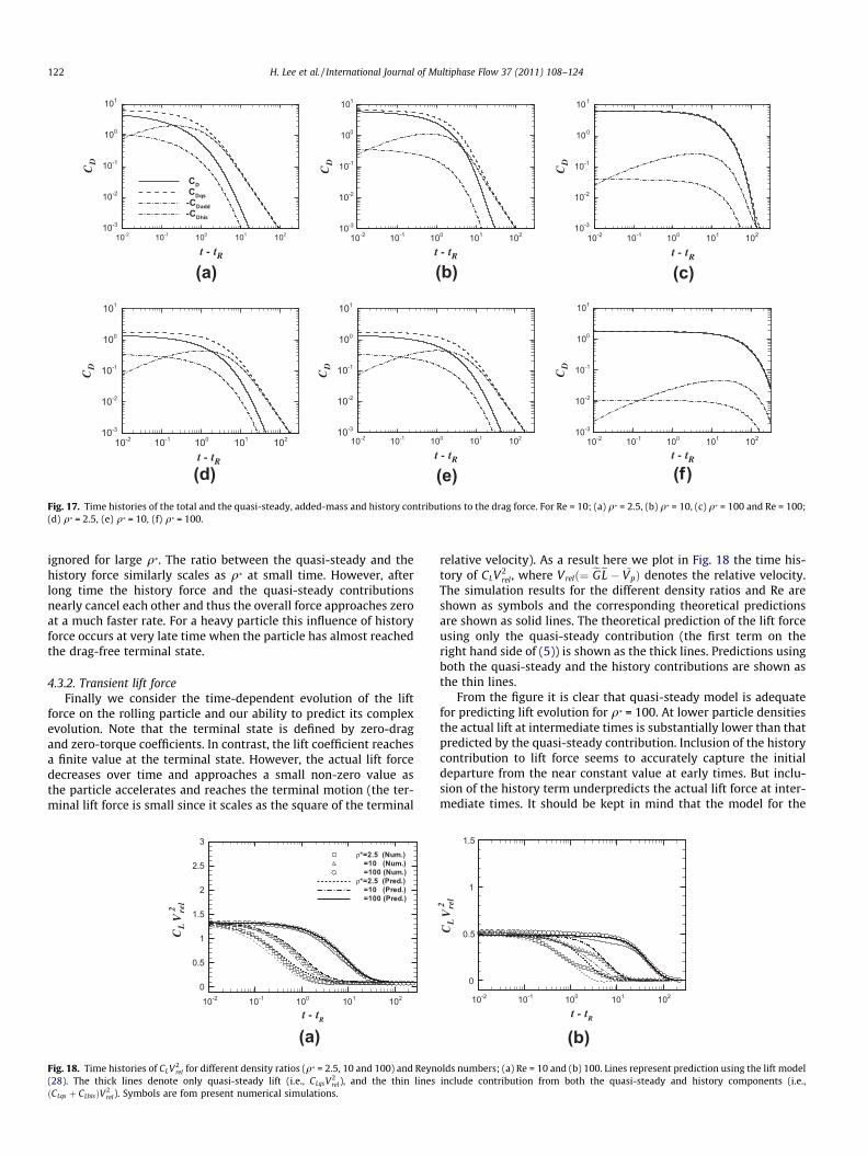
t - tR
CD
10-2 10-1 100 101 10210-3
10-2
10-1
100
101
CDCDqs-CDadd-CDhis
(a)t - tR
CD
10-2 10-1 100 101 10210-3
10-2
10-1
100
101
(b)t - tR
CD
10-2 10-1 100 101 10210-3
10-2
10-1
100
101
(c)
t - tR
CD
10-2 10-1 100 101 10210-3
10-2
10-1
100
101
(d)t - tR
CD
10-2 10-1 100 101 10210-3
10-2
10-1
100
101
(e)t - tR
CD
10-2 10-1 100 101 10210-3
10-2
10-1
100
101
(f)Fig. 17. Time histories of the total and the quasi-steady, added-mass and history contributions to the drag force. For Re = 10; (a) q* = 2.5, (b) q* = 10, (c) q* = 100 and Re = 100;(d) q* = 2.5, (e) q* = 10, (f) q* = 100.
122 H. Lee et al. / International Journal of Multiphase Flow 37 (2011) 108–124
ignored for large q*. The ratio between the quasi-steady and thehistory force similarly scales as q* at small time. However, afterlong time the history force and the quasi-steady contributionsnearly cancel each other and thus the overall force approaches zeroat a much faster rate. For a heavy particle this influence of historyforce occurs at very late time when the particle has almost reachedthe drag-free terminal state.
4.3.2. Transient lift forceFinally we consider the time-dependent evolution of the lift
force on the rolling particle and our ability to predict its complexevolution. Note that the terminal state is defined by zero-dragand zero-torque coefficients. In contrast, the lift coefficient reachesa finite value at the terminal state. However, the actual lift forcedecreases over time and approaches a small non-zero value asthe particle accelerates and reaches the terminal motion (the ter-minal lift force is small since it scales as the square of the terminal
t - tR
CL
Vre
l2
10-2 10-1 100 101 1020
0.5
1
1.5
2
2.5
3ρ*=2.5 (Num.)=10 (Num.)=100 (Num.)
ρ*=2.5 (Pred.)=10 (Pred.)=100 (Pred.)
(a)Fig. 18. Time histories of CLV2
rel for different density ratios (q* = 2.5, 10 and 100) and Reyn(28). The thick lines denote only quasi-steady lift (i.e., CLqsV
2rel), and the thin lines
ðCLqs þ CLhisÞV2rel). Symbols are fom present numerical simulations.
relative velocity). As a result here we plot in Fig. 18 the time his-tory of CLV2
rel, where Vrelð¼ eGeL � ~VpÞ denotes the relative velocity.The simulation results for the different density ratios and Re areshown as symbols and the corresponding theoretical predictionsare shown as solid lines. The theoretical prediction of the lift forceusing only the quasi-steady contribution (the first term on theright hand side of (5)) is shown as the thick lines. Predictions usingboth the quasi-steady and the history contributions are shown asthe thin lines.
From the figure it is clear that quasi-steady model is adequatefor predicting lift evolution for q* = 100. At lower particle densitiesthe actual lift at intermediate times is substantially lower than thatpredicted by the quasi-steady contribution. Inclusion of the historycontribution to lift force seems to accurately capture the initialdeparture from the near constant value at early times. But inclu-sion of the history term underpredicts the actual lift force at inter-mediate times. It should be kept in mind that the model for the
t - tR
10-2 10-1 100 101 1020
0.5
1
1.5
(b)
CL
Vre
l2
olds numbers; (a) Re = 10 and (b) 100. Lines represent prediction using the lift modelinclude contribution from both the quasi-steady and history components (i.e.,

H. Lee et al. / International Journal of Multiphase Flow 37 (2011) 108–124 123
quasi-steady lift force is well formulated and reasonably tested inLee and Balachandar (2010), while the history model presented in(18) is incomplete and it does not include the effect of the wall andhas not been rigorously tested. Thus, we summarize that the his-tory contribution to lift force can be important for smaller densityratio, but our current knowledge of the lift history kernel, espe-cially including the influence of a nearby wall, is quite limited tomake accurate prediction.
5. Conclusions
Here we have performed DNS of different configurations of aparticle rolling on a horizontal flat wall in a linear shear flow.We varied the dimensionless translational velocity in the rangeof �1 to 1 (Vp = �1, �0.5, 0, 0.25, 0.5, 0.75 and 1) and the Reynoldsnumber based on local shear velocity was varied from 1 to 100(Re = 1, 10, 50 and 100). The results from the simulations are usedto validate the drag and lift force superposition models presentedin Lee and Balachandar (2010).
First we considered cases where a steady translational motionwas enforced on the particle and both motion along and againstthe shear flow were considered. In all these cases the particlewas allowed to perfectly roll and as a result all three mechanismsof shear, translation and rotation were simultaneously present. Theresults of the numerical simulation were compared against thedrag and lift relations of Lee and Balachandar (2010). The abovecases of perfect rolling together with the cases of perfect slidingconsidered earlier provide adequate coverage for intermediatecases of partial rolling as well and thus offer detailed validationfor the drag and lift relations.
In the next set of simulations the particles were first held fixedin a wall-bounded shear flow and at t = tR the particle was releasedand allowed to accelerate and reach the terminal drag-free steadystate. The computed terminal translational and rotational veloci-ties of the particle were favorably compared against their predic-tions using the drag relation. The present numerical simulationsof a freely rolling particle at Reynolds numbers of O(1) yielded avalue of about 0.3 for (1 �Xss/Xf), which was consistent with thezero Reynolds number prediction that (1 �Xss/Xf) ? 0.447. Thusthe behavior close to a flat wall was different from the unboundedflow condition, where the particle rotation-rate rapidly approachesthe local fluid rotation-rate as Rer ? 0. In all the cases the particlewas observed to partially roll and partially slip, with ass in therange 0.4–0.6.
Complete expressions for drag and lift in terms of Res, Ret andReX were available, but the corresponding expression for torqueat finite Reynolds numbers is not available. As a result it is not pos-sible to solve for the steady state Vpss and Xss in a coupled manner.Here we assume the terminal rotation-rate of the particle to beknown and solve only the equation of translational motion andpredict the terminal drag-free translational velocity of the particle.It was observed that the predicted terminal translational velocityof the particle was not strongly dependent of the assumed valueof terminal rotation-rate. Over the range of parameters consideredthe computed terminal translational velocity of the particle rangedfrom 60 to 80% of the local shear flow velocity at the center of theparticle and compared well with the prediction. Similarly the ter-minal lift force on the particle was also not very sensitive to therotation-rate and well captured CLss obtained in the simulations.
Finally we consider the time varying drag and lift forces and theapproach to the drag-free, torque-free terminal steady state. Herein addition to the proposed model for the quasi-steady drag and liftforces, accurate models of added-mass and viscous history forcesare required. In particular, it is observed that the presence of thewall has a strong effect on the unsteady added-mass and history
forces. Here we use the recent results of Kharlamov et al. (2007)for the wall effect on added-mass coefficient and the model pro-posed by Yang (2006) for the wall effect on the drag history kernelto obtain an extended equation of motion for the particle that fullyincorporates the effect of the wall. The model is quite accurate inpredicting the time-dependent rolling motion of the particle. It isobserved that the viscous history contribution to the lift forcecan be significant. However further development is needed to-wards establishing a reliable lift history kernel.
Acknowledgments
The authors acknowledge the University of Florida High-Perfor-mance Computing Center for providing computational resourcesand support that have contributed to the research results reportedwithin this paper. This work was partially supported by the KoreanResearch Foundation Grant funded by the Korean Government(KRF-2007-357-D00032).
References
Asmolov, E.S., McLaughlin, J.B., 1999. The inertial lift on an oscillating sphere in alinear shear flow. Int. J. Multiphase Flow 25, 739–751.
Bagchi, P., Balachandar, S., 2002. Effect of free rotation on the motion of a solidsphere in linear shear flow at moderate Re. Phys. Fluids 14, 2719–2737.
Chakraborty, P., Balachandar, S., Adrian, R.J., 2005. On the relationships betweenlocal vortex identification schemes. J. Fluid Mech. 535, 189–214.
Chang, E.J., Maxey, M.R., 1994. Unsteady-flow about a sphere at low to moderateReynolds-number 1. Oscillatory motion. J. Fluid Mech. 277, 347–379.
Chang, E.J., Maxey, M.R., 1995. Unsteady-flow about a sphere at low to moderateReynolds-number 2. Accelerated motion. J. Fluid Mech. 303, 133–153.
Ding, E.J., Aidun, C.K., 2000. The dynamics and scaling law for particles suspended inshear flow with inertia. J. Fluid Mech. 423, 317–344.
Goldman, A., Cox, R.G., Brenner, H., 1967a. Slow viscous motion of a sphere parallelto a plane wall – I. Motion through a quiescent fluid. Chem. Eng. Sci. 22, 637–651.
Goldman, A., Cox, R.G., Brenner, H., 1967b. Slow viscous motion of a sphere parallelto a plane wall – II. Couette flow. Chem. Eng. Sci. 22, 653–660.
Harada, S., Tanaka, T., Tsuji, Y., 2001. Fluid force acting on a particle falling toward awall. JSME Int. J. 44, 520–525.
Kendoush, A.A., Sulaymon, A.H., Mohammed, S.A.M., 2007. Experimental evaluationof the virtual mass of two solid spheres accelerating in fluids. Exp. Therm. FluidSci. 31, 813–823.
Kharlamov, A.A., Chára, Z., Vlasák, P., 2007. Hydraulic formulae for the addedmasses of an impermeable sphere moving near a plane wall. J. Eng. Math. 62,161–172.
Kim, I., Elghobashi, S., Sirignano, W.A., 1998. On the equation for spherical particlemotion: effect of Reynolds and acceleration numbers. J. Fluid Mech. 367, 221–253.
King, M.R., Leighton, D.T., 1997. Measurement of the inertial lift on a moving spherein contact with a plane wall in a shear flow. Phys. Fluids 9, 1248–1255.
Kossack, C.A., Acrivos, A., 1974. Steady simple shear flow past a circular cylinder atmoderate Reynolds numbers: a numerical solution. J. Fluid Mech. 66, 353–376.
Krishnan, G.P., Leighton, D.T., 1995. Inertial lift on a moving sphere in contact with aplane wall in a shear flow. Phys. Fluids 7, 2538–2545.
Lamb, H., 1932. Hydrodynamics, sixth ed. Cambridge University Press, Cambridge.Lawrence, C.J., Mei, R., 1995. Long-time behaviour of the drag on a body in impulsive
motion. J. Fluid Mech. 283, 307–327.Lee, H., Balachandar, S., 2010. Drag and lift forces on a spherical particle moving on a
wall in a shear flow at finite Re. J. Fluid Mech. 657, 89–125.Legendre, D., Magnaudet, J., 1998. The lift force on a spherical bubble in a viscous
linear shear flow. J. Fluid Mech. 368, 81–126.Lovalenti, P.M., Brady, J.F., 1993a. The force on a sphere in a uniform flow with
small-amplitude oscillations at finite Reynolds number. J. Fluid Mech. 256, 607–614.
Lovalenti, P.M., Brady, J.F., 1993b. The hydrodynamic force on a rigid particleundergoing arbitrary time-dependent motion at small Reynolds number. J.Fluid Mech. 256, 561–605.
Lovalenti, P.M., Brady, J.F., 1995. The temporal behaviour of the hydrodynamic forceon a body in response to an abrupt change in velocity at small but finiteReynolds number. J. Fluid Mech. 293, 35–46.
Mei, R., 1993. History force on a sphere due to a step change in the free-streamvelocity. Int. J. Multiphase flow 19, 509–525.
Mei, R., Adrian, R.J., 1992. Flow past a sphere with an oscillation in the free-streamand unsteady drag at finite Reynolds number. J. Fluid Mech. 237, 323–341.
Rivero, M., Magnaudet, J., Fabre, J., 1991. New results on the forces exerted on aspherical body by an accelerated flow. C.R. Acad. Sci. Paris 312, 1499–1506.
Stewart, B.E., Thompson, M.C., Leweke, T., Hourigan, K., 2010. Numerical andexperimental studies of the rolling sphere wake. J. Fluid Mech. 643, 137–162.

124 H. Lee et al. / International Journal of Multiphase Flow 37 (2011) 108–124
Takemura, F., Magnaudet, J., 2003. The transverse force on clean and contaminatedbubbles rising near a vertical wall at moderate Reynolds number. J. Fluid Mech.495, 235–253.
Uhlmann, M., 2005. An immersed boundary method with direct forcing for thesimulation of particulate flows. J. Comput. Phys. 209, 448–476.
Wakaba, L., Balachandar, S., 2005. History force on a sphere in a weak linear shearflow. Int. J. Multiphase Flow 31, 996–1014.
Wakaba, L., Balachandar, S., 2007. On the added mass force at finite Reynolds andacceleration numbers. Theor. Comput. Fluid Dyn. 21, 147–153.
Yang, F.-L., 2006. Interaction law for a collision between two solid particles in a viscousliquid. Ph.D. thesis, California Institute of Technology, Pasadena, California.
Zeng, L., Balachandar, S., Fisher, P., 2005. Wall-induced forces on a rigid sphere atfinite Reynolds number. J. Fluid Mech. 536, 1–25.
Zeng, L., Najjar, F., Balachandar, S., Fisher, P., 2009. Forces on a finite-sized particlelocated close to a wall in a linear shear flow. Phys. Fluids 21, 033302.
Zhou, J., Adrian, R.J., Balachandar, S., Kendall, T.M., 1999. Mechanisms for generatingcoherent packets of hairpin vortices in channel flow. J. Fluid Mech. 387, 353–396.


![Subsurface Stresses in Rolling & Sliding Machine Components [Sadeghi, Sui; Int.comp.Eng.conf., 1988]](https://static.fdocuments.us/doc/165x107/577cd14b1a28ab9e7894160a/subsurface-stresses-in-rolling-sliding-machine-components-sadeghi-sui.jpg)