Rolling bearings — Needle roller bearings, drawn cup ...thietkemay.com/uploads/userfiles/file/BS...
14
BRITISH STANDARD BS ISO 3245:2007 Rolling bearings — Needle roller bearings, drawn cup without inner ring — Boundary dimensions and tolerances ICS 21.100.20
Transcript of Rolling bearings — Needle roller bearings, drawn cup ...thietkemay.com/uploads/userfiles/file/BS...
BRITISH STANDARD
BS ISO 3245:2007Rolling bearings — Needle roller bearings, drawn cup without inner ring — Boundary dimensions and tolerances
ICS 21.100.20
�������������� ���������������������������������������������������
BS ISO 3245:2007
This British Standard was published under the authority of the Standards Policy and Strategy Committee on 31 March 2008
© BSI 2008
ISBN 978 0 580 54884 0
National foreword
This British Standard is the UK implementation of ISO 3245:2007. It supersedes BS ISO 3245:1997 which is withdrawn.The UK participation in its preparation was entrusted to Technical Committee MCE/7, Rolling bearings.A list of organizations represented on this committee can be obtained on request to its secretary.This publication does not purport to include all the necessary provisions of a contract. Users are responsible for its correct application.Compliance with a British Standard cannot confer immunity from legal obligations.
Amendments/corrigenda issued since publication
Date Comments
Reference numberISO 3245:2007(E)
INTERNATIONAL STANDARD
ISO3245
Third edition2007-12-01
Rolling bearings — Needle roller bearings, drawn cup without inner ring —Boundary dimensions and tolerances
Roulements — Douilles à aiguilles sans bague intérieure — Dimensions d'encombrement et tolérances
BS ISO 3245:2007

ii
iii
Foreword
ISO (the International Organization for Standardization) is a worldwide federation of national standards bodies (ISO member bodies). The work of preparing International Standards is normally carried out through ISO technical committees. Each member body interested in a subject for which a technical committee has been established has the right to be represented on that committee. International organizations, governmental and non-governmental, in liaison with ISO, also take part in the work. ISO collaborates closely with the International Electrotechnical Commission (IEC) on all matters of electrotechnical standardization.
International Standards are drafted in accordance with the rules given in the ISO/IEC Directives, Part 2.
The main task of technical committees is to prepare International Standards. Draft International Standards adopted by the technical committees are circulated to the member bodies for voting. Publication as an International Standard requires approval by at least 75 % of the member bodies casting a vote.
Attention is drawn to the possibility that some of the elements of this document may be the subject of patent rights. ISO shall not be held responsible for identifying any or all such patent rights.
ISO 3245 was prepared by Technical Committee ISO/TC 4, Rolling bearings, Subcommittee SC 5, Needle roller bearings.
This third edition cancels and replaces the second edition (ISO 3245:1997), which has been technically revised.
BS ISO 3245:2007

blank
1
Rolling bearings — Needle roller bearings, drawn cup without inner ring — Boundary dimensions and tolerances
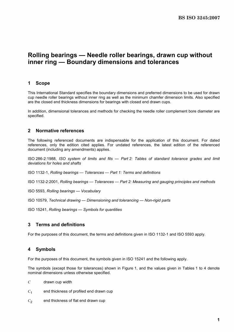
1 Scope
This International Standard specifies the boundary dimensions and preferred dimensions to be used for drawn cup needle roller bearings without inner ring as well as the minimum chamfer dimension limits. Also specified are the closed end thickness dimensions for bearings with closed end drawn cups.
In addition, dimensional tolerances and methods for checking the needle roller complement bore diameter are specified.
2 Normative references
The following referenced documents are indispensable for the application of this document. For dated references, only the edition cited applies. For undated references, the latest edition of the referenced document (including any amendments) applies.
ISO 286-2:1988, ISO system of limits and fits — Part 2: Tables of standard tolerance grades and limit deviations for holes and shafts
ISO 1132-1, Rolling bearings — Tolerances — Part 1: Terms and definitions
ISO 1132-2:2001, Rolling bearings — Tolerances — Part 2: Measuring and gauging principles and methods
ISO 5593, Rolling bearings — Vocabulary
ISO 10579, Technical drawing — Dimensioning and tolerancing — Non-rigid parts
ISO 15241, Rolling bearings — Symbols for quantities
3 Terms and definitions
For the purposes of this document, the terms and definitions given in ISO 1132-1 and ISO 5593 apply.
4 Symbols
For the purposes of this document, the symbols given in ISO 15241 and the following apply.
The symbols (except those for tolerances) shown in Figure 1, and the values given in Tables 1 to 4 denote nominal dimensions unless otherwise specified.
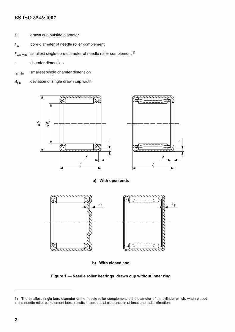
C drawn cup width
C1 end thickness of profiled end drawn cup
C2 end thickness of flat end drawn cup
BS ISO 3245:2007
2
D drawn cup outside diameter
Fw bore diameter of needle roller complement
Fws min smallest single bore diameter of needle roller complement 1)
r chamfer dimension
rs min smallest single chamfer dimension
∆Cs deviation of single drawn cup width
a) With open ends
b) With closed end
Figure 1 — Needle roller bearings, drawn cup without inner ring
1) The smallest single bore diameter of the needle roller complement is the diameter of the cylinder which, when placed in the needle roller complement bore, results in zero radial clearance in at least one radial direction.
BS ISO 3245:2007
3
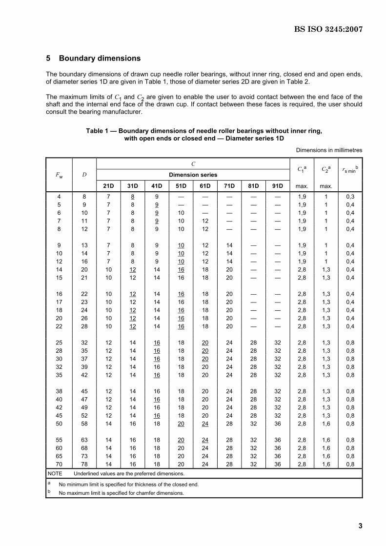
5 Boundary dimensions
The boundary dimensions of drawn cup needle roller bearings, without inner ring, closed end and open ends, of diameter series 1D are given in Table 1, those of diameter series 2D are given in Table 2.
The maximum limits of C1 and C2 are given to enable the user to avoid contact between the end face of the shaft and the internal end face of the drawn cup. If contact between these faces is required, the user should consult the bearing manufacturer.
Table 1 — Boundary dimensions of needle roller bearings without inner ring, with open ends or closed end — Diameter series 1D
Dimensions in millimetres
C
Dimension series C1
a C2a rs min
b Fw D
21D 31D 41D 51D 61D 71D 81D 91D max. max.
4 8 7 8 9 — — — — — 1,9 1 0,3 5 9 7 8 9 — — — — — 1,9 1 0,4 6 10 7 8 9 10 — — — — 1,9 1 0,4 7 11 7 8 9 10 12 — — — 1,9 1 0,4 8 12 7 8 9 10 12 — — — 1,9 1 0,4
9 13 7 8 9 10 12 14 — — 1,9 1 0,4 10 14 7 8 9 10 12 14 — — 1,9 1 0,4 12 16 7 8 9 10 12 14 — — 1,9 1 0,4 14 20 10 12 14 16 18 20 — — 2,8 1,3 0,4 15 21 10 12 14 16 18 20 — — 2,8 1,3 0,4
16 22 10 12 14 16 18 20 — — 2,8 1,3 0,4 17 23 10 12 14 16 18 20 — — 2,8 1,3 0,4 18 24 10 12 14 16 18 20 — — 2,8 1,3 0,4 20 26 10 12 14 16 18 20 — — 2,8 1,3 0,4 22 28 10 12 14 16 18 20 — — 2,8 1,3 0,4
25 32 12 14 16 18 20 24 28 32 2,8 1,3 0,8 28 35 12 14 16 18 20 24 28 32 2,8 1,3 0,8 30 37 12 14 16 18 20 24 28 32 2,8 1,3 0,8 32 39 12 14 16 18 20 24 28 32 2,8 1,3 0,8 35 42 12 14 16 18 20 24 28 32 2,8 1,3 0,8
38 45 12 14 16 18 20 24 28 32 2,8 1,3 0,8 40 47 12 14 16 18 20 24 28 32 2,8 1,3 0,8 42 49 12 14 16 18 20 24 28 32 2,8 1,3 0,8 45 52 12 14 16 18 20 24 28 32 2,8 1,3 0,8 50 58 14 16 18 20 24 28 32 36 2,8 1,6 0,8
55 63 14 16 18 20 24 28 32 36 2,8 1,6 0,8 60 68 14 16 18 20 24 28 32 36 2,8 1,6 0,8 65 73 14 16 18 20 24 28 32 36 2,8 1,6 0,8 70 78 14 16 18 20 24 28 32 36 2,8 1,6 0,8
NOTE Underlined values are the preferred dimensions.
a No minimum limit is specified for thickness of the closed end. b No maximum limit is specified for chamfer dimensions.
BS ISO 3245:2007
4
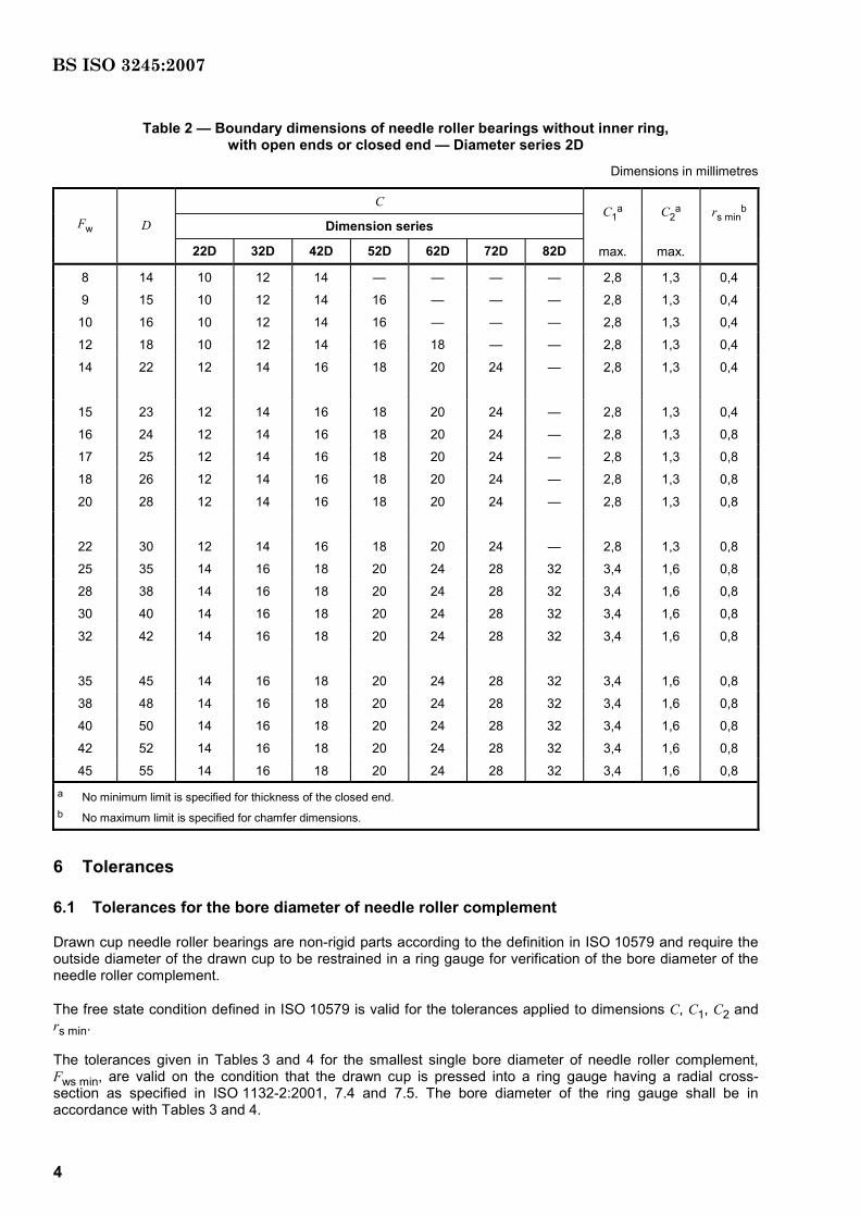
Table 2 — Boundary dimensions of needle roller bearings without inner ring, with open ends or closed end — Diameter series 2D
Dimensions in millimetres
C
Dimension series C1
a C2a rs min
b Fw D
22D 32D 42D 52D 62D 72D 82D max. max.
8 14 10 12 14 — — — — 2,8 1,3 0,4
9 15 10 12 14 16 — — — 2,8 1,3 0,4
10 16 10 12 14 16 — — — 2,8 1,3 0,4
12 18 10 12 14 16 18 — — 2,8 1,3 0,4
14 22 12 14 16 18 20 24 — 2,8 1,3 0,4
15 23 12 14 16 18 20 24 — 2,8 1,3 0,4
16 24 12 14 16 18 20 24 — 2,8 1,3 0,8
17 25 12 14 16 18 20 24 — 2,8 1,3 0,8
18 26 12 14 16 18 20 24 — 2,8 1,3 0,8
20 28 12 14 16 18 20 24 — 2,8 1,3 0,8
22 30 12 14 16 18 20 24 — 2,8 1,3 0,8
25 35 14 16 18 20 24 28 32 3,4 1,6 0,8
28 38 14 16 18 20 24 28 32 3,4 1,6 0,8
30 40 14 16 18 20 24 28 32 3,4 1,6 0,8
32 42 14 16 18 20 24 28 32 3,4 1,6 0,8
35 45 14 16 18 20 24 28 32 3,4 1,6 0,8
38 48 14 16 18 20 24 28 32 3,4 1,6 0,8
40 50 14 16 18 20 24 28 32 3,4 1,6 0,8
42 52 14 16 18 20 24 28 32 3,4 1,6 0,8
45 55 14 16 18 20 24 28 32 3,4 1,6 0,8 a No minimum limit is specified for thickness of the closed end. b No maximum limit is specified for chamfer dimensions.
6 Tolerances
6.1 Tolerances for the bore diameter of needle roller complement
Drawn cup needle roller bearings are non-rigid parts according to the definition in ISO 10579 and require the outside diameter of the drawn cup to be restrained in a ring gauge for verification of the bore diameter of the needle roller complement.
The free state condition defined in ISO 10579 is valid for the tolerances applied to dimensions C, C1, C2 and rs min.
The tolerances given in Tables 3 and 4 for the smallest single bore diameter of needle roller complement, Fws min, are valid on the condition that the drawn cup is pressed into a ring gauge having a radial cross-section as specified in ISO 1132-2:2001, 7.4 and 7.5. The bore diameter of the ring gauge shall be in accordance with Tables 3 and 4.
BS ISO 3245:2007
5
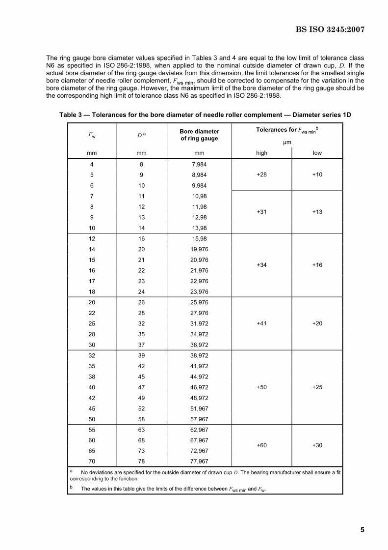
The ring gauge bore diameter values specified in Tables 3 and 4 are equal to the low limit of tolerance class N6 as specified in ISO 286-2:1988, when applied to the nominal outside diameter of drawn cup, D. If the actual bore diameter of the ring gauge deviates from this dimension, the limit tolerances for the smallest single bore diameter of needle roller complement, Fws min, should be corrected to compensate for the variation in the bore diameter of the ring gauge. However, the maximum limit of the bore diameter of the ring gauge should be the corresponding high limit of tolerance class N6 as specified in ISO 286-2:1988.
Table 3 — Tolerances for the bore diameter of needle roller complement — Diameter series 1D
Tolerances for Fws minb
Fw D a Bore diameter of ring gauge µm
mm mm mm high low
4 8 7,984
5 9 8,984
6 10 9,984
+28 +10
7 11 10,98
8 12 11,98
9 13 12,98
10 14 13,98
+31 +13
12 16 15,98
14 20 19,976
15 21 20,976
16 22 21,976
17 23 22,976
18 24 23,976
+34 +16
20 26 25,976
22 28 27,976
25 32 31,972
28 35 34,972
30 37 36,972
+41 +20
32 39 38,972
35 42 41,972
38 45 44,972
40 47 46,972
42 49 48,972
45 52 51,967
50 58 57,967
+50 +25
55 63 62,967
60 68 67,967
65 73 72,967
70 78 77,967
+60 +30
a No deviations are specified for the outside diameter of drawn cup D. The bearing manufacturer shall ensure a fit corresponding to the function. b The values in this table give the limits of the difference between Fws min and Fw.
BS ISO 3245:2007
6
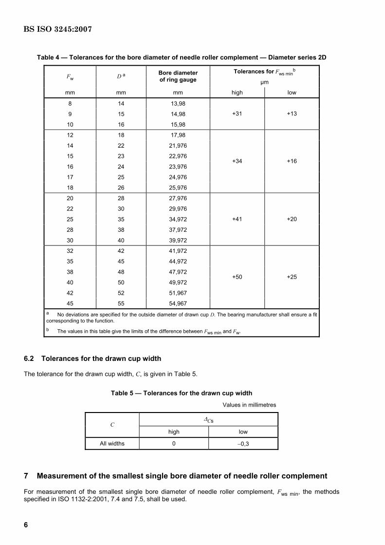
Table 4 — Tolerances for the bore diameter of needle roller complement — Diameter series 2D
Tolerances for Fws minb
Fw D a Bore diameter of ring gauge µm
mm mm mm high low
8 14 13,98
9 15 14,98
10 16 15,98
+31 +13
12 18 17,98
14 22 21,976
15 23 22,976
16 24 23,976
17 25 24,976
18 26 25,976
+34 +16
20 28 27,976
22 30 29,976
25 35 34,972
28 38 37,972
30 40 39,972
+41 +20
32 42 41,972
35 45 44,972
38 48 47,972
40 50 49,972
42 52 51,967
45 55 54,967
+50 +25
a No deviations are specified for the outside diameter of drawn cup D. The bearing manufacturer shall ensure a fit corresponding to the function. b The values in this table give the limits of the difference between Fws min and Fw.
6.2 Tolerances for the drawn cup width
The tolerance for the drawn cup width, C, is given in Table 5.
Table 5 — Tolerances for the drawn cup width
Values in millimetres
∆Cs C
high low
All widths 0 −0,3
7 Measurement of the smallest single bore diameter of needle roller complement
For measurement of the smallest single bore diameter of needle roller complement, Fws min, the methods specified in ISO 1132-2:2001, 7.4 and 7.5, shall be used.
BS ISO 3245:2007

blank
BS ISO 3245:2007
BSI389 Chiswick High RoadLondonW4 4AL
BSI — British Standards InstitutionBSI is the independent national body responsible for preparing British Standards. It presents the UK view on standards in Europe and at the international level. It is incorporated by Royal Charter.
Revisions
British Standards are updated by amendment or revision. Users of British Standards should make sure that they possess the latest amendments or editions.
It is the constant aim of BSI to improve the quality of our products and services. We would be grateful if anyone finding an inaccuracy or ambiguity while using this British Standard would inform the Secretary of the technical committee responsible, the identity of which can be found on the inside front cover. Tel: +44 (0)20 8996 9000. Fax: +44 (0)20 8996 7400.
BSI offers members an individual updating service called PLUS which ensures that subscribers automatically receive the latest editions of standards.
Buying standards
Orders for all BSI, international and foreign standards publications should be addressed to Customer Services. Tel: +44 (0)20 8996 9001. Fax: +44 (0)20 8996 7001. Email: [email protected]. Standards are also available from the BSI website at http://www.bsi-global.com.
In response to orders for international standards, it is BSI policy to supply the BSI implementation of those that have been published as British Standards, unless otherwise requested.
Information on standards
BSI provides a wide range of information on national, European and international standards through its Library and its Technical Help to Exporters Service. Various BSI electronic information services are also available which give details on all its products and services. Contact the Information Centre. Tel: +44 (0)20 8996 7111. Fax: +44 (0)20 8996 7048. Email: [email protected].
Subscribing members of BSI are kept up to date with standards developments and receive substantial discounts on the purchase price of standards. For details of these and other benefits contact Membership Administration. Tel: +44 (0)20 8996 7002. Fax: +44 (0)20 8996 7001. Email: [email protected].
Information regarding online access to British Standards via British Standards Online can be found at http://www.bsi-global.com/bsonline.
Further information about BSI is available on the BSI website at http://www.bsi-global.com.
Copyright
Copyright subsists in all BSI publications. BSI also holds the copyright, in the UK, of the publications of the international standardization bodies. Except as permitted under the Copyright, Designs and Patents Act 1988 no extract may be reproduced, stored in a retrieval system or transmitted in any form or by any means – electronic, photocopying, recording or otherwise – without prior written permission from BSI.
This does not preclude the free use, in the course of implementing the standard, of necessary details such as symbols, and size, type or grade designations. If these details are to be used for any other purpose than implementation then the prior written permission of BSI must be obtained.
Details and advice can be obtained from the Copyright & Licensing Manager. Tel: +44 (0)20 8996 7070. Fax: +44 (0)20 8996 7553. Email: [email protected].