Roll control of submarines. - Internet Archive · 2012. 9. 13. · InitialRollAngle=-5...
394
ROLL CONTROL OF SUBMARINES Izzet Artunc
Transcript of Roll control of submarines. - Internet Archive · 2012. 9. 13. · InitialRollAngle=-5...

ROLL CONTROL OF SUBMARINES
Izzet Artunc

:hooi

NAVAL POSTGRADUATE SCHOOLMonterey, California
THESISROLL CONTROL OF SUBMARINES
by
Izzet Artunc
December 1979
Thesis Advisor: G.J. Thaler
Approved For Public Release; Distribution Unlimited,
1191351


UNCLASSIFIED
SECUMITY CLASSIFICATION OF THIS PACE fWttan Dmim EntmfH)
REPORT DOCUMENTATION PAGE READ INSTRUCTTONSBEFORE COMPLETING FORM
! NC^OMT NUMCCM 2. OOVT ACCCSSiOM NO. > RECIPIENT'S CATALOG NUMBER
4. TITLE rand StihUlla)
Roll Control Of Submarines
5. TYRE OF REPORT * RERIOO COVERED
Master's ThesisDecember 1979
a. RtArORMING ORG. REPORT NUMBER
7. AuTMO»»CiJ
Tzzet Artunc
• CONTRACT OR GRANT NUMBER^*)
• ^EffFOMMIMa OnOAMlZATlON NAME ANO AOOAtit
Naval Postgraduate SchoolMonterey, California 93940
10. PROGRAM ELEMENT. PROJECT. TASKAREA * WORK UNIT NUMBERS
1 1 CONTROL LING OFFICE NAME ANO AOOMESS
Naval Postgraduate SchoolMonterey, California 93940
12. REPORT DATEDecember 1979
tS. NUMBER OF PAGES
19414. MONlToniNG AGENCY NAME * AODWESSCK dtltmrmnl /ram Coniroinnf Olllem) IS. SECURITY CLASS, (ol thit riport)
Unclassified
ISa. OICLASSIFI CATION/ DOWN GRADINGSCHEDULE
16. DISTRIBUTION STATEMENT (of /*»<• Mtpart)
Aoproved for public release; distribution unlimited.
)7. OISTMIBUTION STATEMENT (of (h* afearracr antararf In Bloek 30, It dHI»Twnt /ran Ktiporl)
H. SUPPLEMENTARY NOTES
It. KEY WORDS fCanr/nua on rarara* midm II ntcamaarr tmd Idftlify kr block numkmr)
Depth Pitch Roll Control Of Submarines
Differentially Deflected Fairwater Planes
20. ABSTRACT (ConlImM an fvtrm* alda II n»emuusrr "td ld»ntltr kf kl»ek mmtk^r)
The use of differentially deflected fairwater olanes to con-trol submarine rolling is studied. Because of couplina betweenDitch and roll angles, the snao roll that occurs in a high speedhard turn affects the stability of a submarine not only in thehorizontal plane but also in the vertical nlane. Direct rollcontrol was achieved by making use of the fairwater nlanes in adifferentially deflected mode such that they could give counter
DOI JAN 71 1473 EDITION OF I NOV •• U OBSOLtTE
(Page 1) S/N 0103*014- AAOli
UMCLASSIFIEDSICURITY CLASSIFICATION OF THIS PAOl (Whmt Dmtm Knffd)


UNCLASSIFIED$mcumr* eu *«t«y'C * tiqk o> tmi* mtoirw*,^, n««« «•«•»•«
moment to reduce the snap roll. A roll controller was de-signed as a position and velocity feedback controller. Con-trolled roll angle imoroved the depth and nitch stability ofsubmarine.
°°1 Jan^3
^'^''^ UNCLASSIFIED5/N 0102-014-6601 _ ticu*iTv CLAtsincAriOM o^ '^nh ^•acr«f««" o««« *»>•'•«)
X

Approved For Public Release; Distribution Unlimited,
Roll Control Of Submarines
by
Izzet ArtuncLieutenant, Turkish Navy
B.3.E.E*, Naval Postgraduate School, 1979
Submitted In Partial Fulfillment Of TheRequirements For The Degree Of
MASTER OF SCIENCE IN ELECTRICAL ENGINEERING
From The
NAVAL POSTGRADUATE SCHOOLDecember 1979

1 ''^-2-iWi

ABSTRACT
The use of differentially deflected fairwater planes
to control submarine rolling is studied. Because of counling
between pitch and roll angles, the snap roll that occurs in
a high speed hard turn affects the stability of a submarine
not only in the horizontal plane but also in the vertical
plane. Direct roll control was achieved by making use of the
fairwater planes in a differentially deflected mode such that
they could give counter moment to reduce the snap roll, A
roll controller was designed as a position and velocity feed-
back controller. Controlled roll angle improved the depth
and pitch stability of submarine.

TABLE OF CONTENTS
LIST OF FIGURES 6
ACKNOI\TiEDGEMENT ^^
I. INTRODUCTION ^^
II. NATURE OF THE PROBLEK 17
III. DIGITAL COMPUTER SIMULATION OF SUBMARINE MOTION 2 6
IV. AUTOMATIC DEPTH AND PITCH CONTROL 4 8
A. OPTIMxAL SOLUTION TO THE LINEARIZEDSUB-MARINE EQUATIONS 48
B. AUTOMATIC DEPTH-PITCH CONTROLLER ANDSIMULATION OF THE RESULT ^5
V. AUTOMJ^TIC ROLL CONTROLLER 88
A. ESTIMJ^TING ROLL MOMENT DUE TODIFFERENTIALLY DEFLECTED SAILPLANES 90
B. POLL CONTROLLER DESIGN 9 3
1, Proportional Controller 96
2. Compensation Of The System WithVelocity Feedback 106
C. ROLL CONTROLLER STABILITY TESTS 15 2
VI. DISCUSSION, CONCLUSIONS AND PJICOMMENDATIONSFOR FURTHER WORK 169
A. DISCUSSION AND CONCLUSION 169
B. RECOMMENDATIONS FOR FURTHER WOPJC 17 2
APPENDIX A: NOTATION AND EQUATIONS OF MOTION 174
APPENDIX B: COMPUTER PROGRAM FOR ROLL CONTROLSIMULATION 186
LIST OF REFERENCES 19 3
INITIAL DISTRIBUTION LIST 1^4


LIST OF FIGURESPage
1. Hydrodynamic Forces In A Turn 20
2. Coordinate System 21
3. Depth vs. Time. With No Controller. UCK = 24 Knots 22Rudder Ordered = 35
4. Pitch vs. Time. With No Controller. UCK = 24 Knots 23Rudder Ordered = 35
5. Roll vs. Time. With No Controller. UCK = 24 Knots 24Rudder Ordered = 35°
6. Rudder Response vs. Time. With No Controller. UCK = 2524 Knots. Rudder Ordered = 35°
7. Rudder Hydraulic Actuator Model 29
8. Depth vs. Time. With No Controller. UCK = 18 Knots 30Rudder Ordered = 35
9. Pitch vs. Time. With No Controller. UCK = 18 Knots 31Rudder Ordered =35°
10. Roll vs. Time. With No Controller. UCK = 18 Knots 32Rudder Ordered = 35°
11. Speed Change vs. Time. With No Controller. UCK = 3318 Knots. Rudder Ordered = 35°
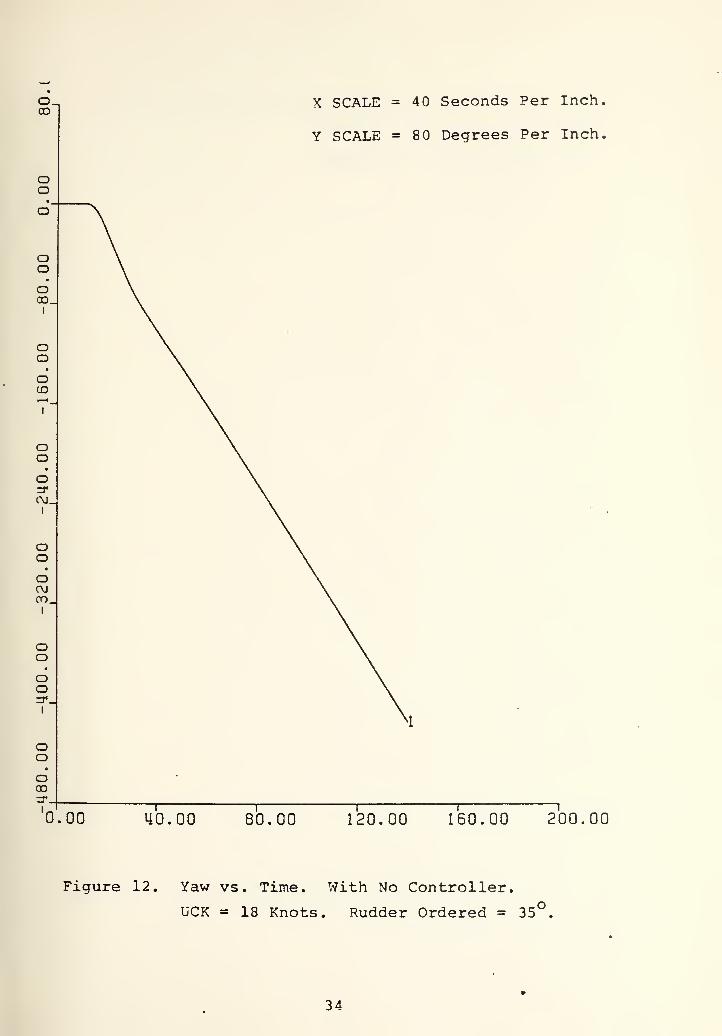
12. Yaw vs. Time. With No Controller. UCK = 18 Knots 34Rudder Ordered = 35°
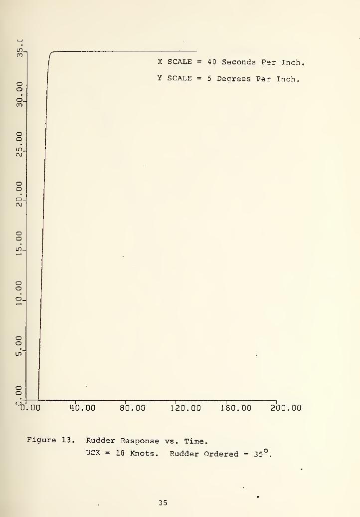
13. Rudder Response vs. Time. With No Controller. 35UCK = 18 Knots. Rudder Ordered = 35°
14. Depth vs. Time. With No Controller. UCK = 12 Knots 36Rudder Ordered = 35°
15. Pitch vs. Time. With No Controller. UCK = 12 Knots 37Rudder ordered = 35°
16. Roll vs. Time. With No Controller. UCK = 12 Knots 38Rudder Ordered = 35
17. Speed Change vs. Time. With No Controller. UCK = 3912 Knots. Rudder Ordered = 35°


Page
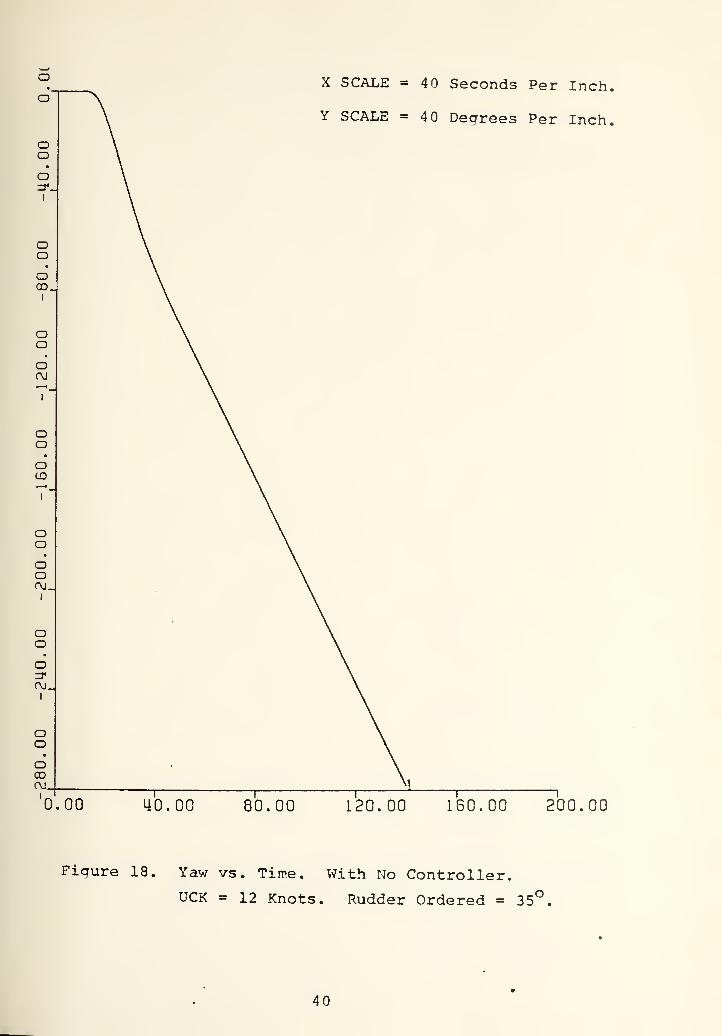
18. Yaw vs. Time. With No Controller. UCK = 12 Knots 40Rudder Ordered = 35
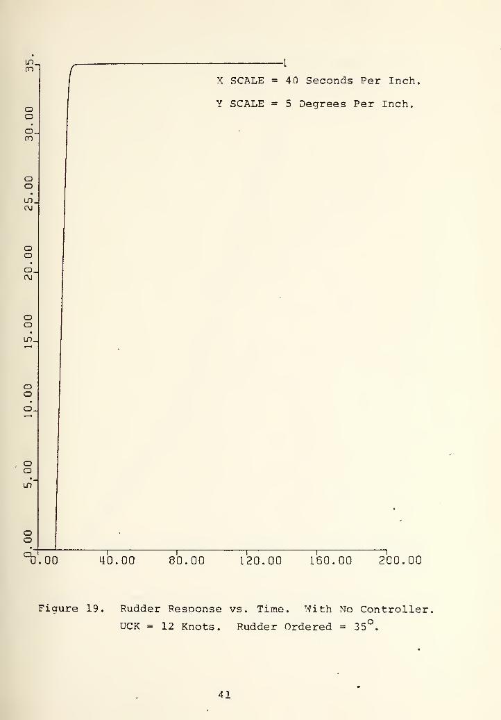
19. Rudder Response vs. Time. With No Controller. 41UCK = 12 Knots. Rudder Ordered = 35
20. Depth vs. Time. With No Controller. UCK = 6 Knots. 42Rudder Ordered = 35
21. Pitch vs. Time. With No Controller. UCK = 6 Knots. 43Rudder Ordered = 35
22. Roll vs. Time. With No Controller. UCK = 6 Knots. 44Rudder Ordered = 35
23. Speed Change vs. Time. With No Controller. 45UCK = 6 Knots. Rudder Ordered =35^
24. Yaw vs. Time. With No Controller. UCK = 6 Knots. 46Rudder Ordered = 35°
25. Rudder Response vs. Time. With No Controller. 47UCK = 6 Knots. Rudder Ordered =35°
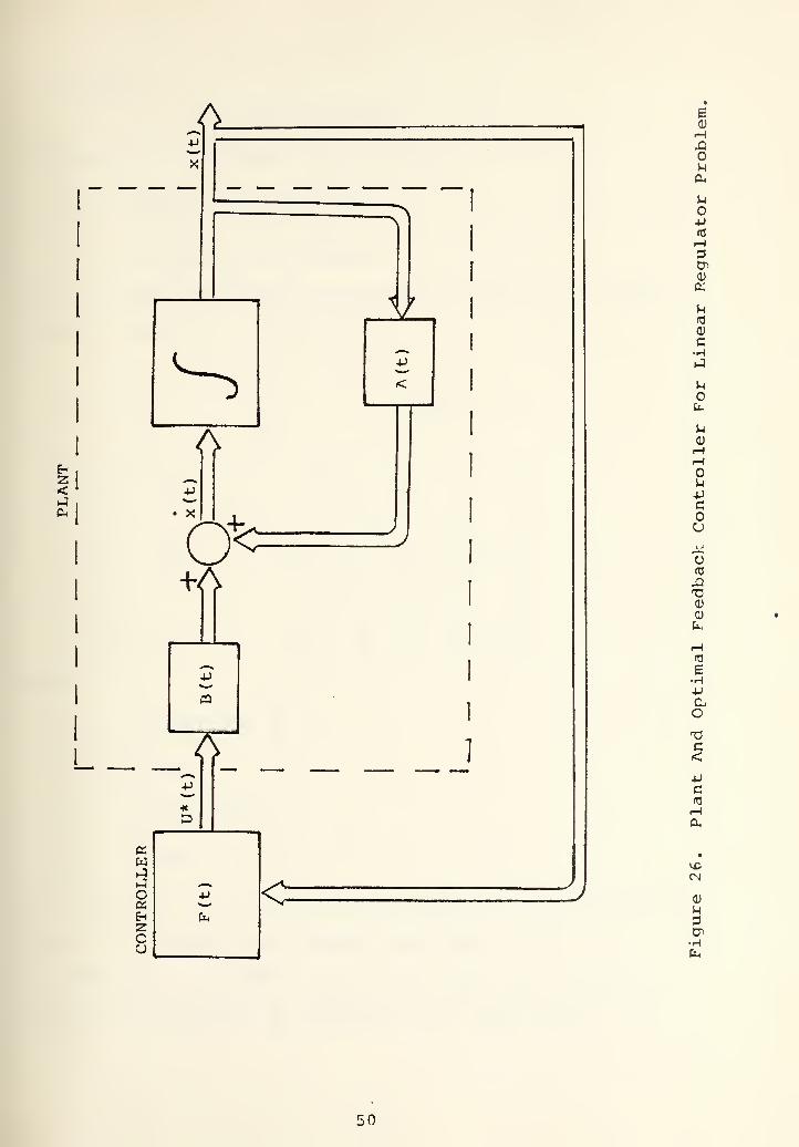
26. Linear Regulator Block Diagram. 50
27. Kll vs. Time 54
28. K12 vs. Time 55
29. K13 vs. Time 56
30. K14 vs. Time 57
31. K22 vs. Time 58
32. K23 vs. Time 59
33. K24 vs. Time 60
34. K33 vs. Time 61
35. K34 vs. Time 62
36. K44 vs. Time 63
37. Kll vs. Time. With Transformation Of Depth Rate = W 64
38. Depth And Pitch Controller Block Diagram 66
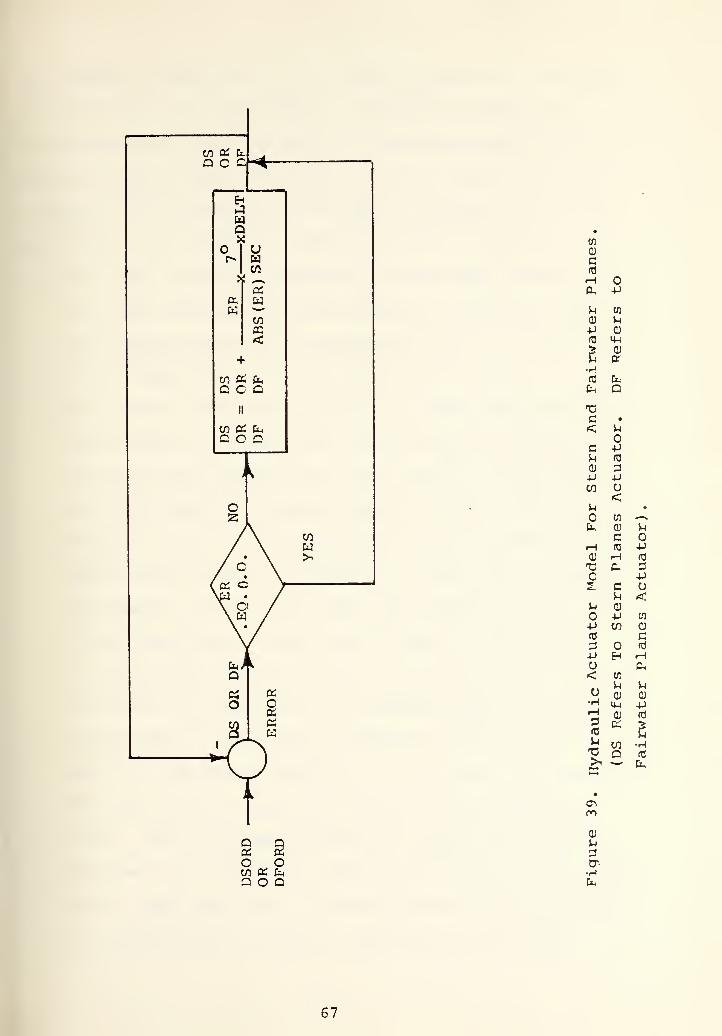
39. Hydraulic Actuator Model For Stern And Fairv/ater Plane 67
40. Depth vs. Time. With Depth-Pitch Controller. 72UCK = 6 Knots. Rudder Ordered = 35°


Page
41. Pitch vs. Time. With Depth-Pitch Controller. 73UCK = 6 Knots. Rudder Ordered = 35
42. Roll vs. Time. With Depth-Pitch Controller. 74UCK = 6 Knots. Rudder Ordered = 35
43. Sternplane Angle vs. Time. With Depth-Pitch ^ 75Controller. UCK = 6 Knots. Rudder Ordered = 35
44. Depth vs. Time. With Depth-Pitch Controller. 76UCK = 12 Knots. Rudder Ordered = 35°
45. Pitch vs. Time. With Depth-Pitch Controller. 77UCK = 12 Knots. Rudder Ordered = 35
46. Roll vs. Time. With Depth-Pitch Controller. 78
UCK = 12 Knots. Rudder Ordered = 35
47. Sternplane Angle vs. Time. With Depth-Pitch 79
Controller. UCK = 12 Knots. Rudder Ordered = 35
48. Depth vs. Time. With Deoth-Pitch Controller. 80
UCK = 18 Knots. Rudder Ordered = 35°
49. Pitch vs. Time. With Depth-Pitch Controller. 81UCK = 18 Knots. Rudder Ordered =35°
50. Roll vs. Time. With Depth-Pitch Controller. 82UCK = 18 Knots. Rudder Ordered = 35°
51. Sternplane Angle vs. Time. With Depth-Pitch 83Controller. UCK = 18 Knots. Rudder Ordered = 35°
52. Depth vs. Time. With Depth-Pitch Controller. 84UCK = 24 Knots. Rudder' Ordered = 35°
53. Pitch vs. Time. With Depth-Pitch Controller,UCK = 24 Knots. Rudder Ordered = 35
85
54. Roll vs. Time. With Depth-Pitch Controller. 86UCK = 24 Knots. Rudder Ordered = 35
55. Sternplane Angle vs. Time. With Deoth-Pitch 87Controller. UCK = 24 Knots. Rudder Ordered = 35°
56. Definition Of Positive Direction Of Differentially 92Deflected Sailplanes
57.1. Basic Position Feedback Control Scheme 95
.2. Basic Position And Velocity Feedback Control Scheme
58. Depth vs. Time. Kl = 3. UCK = 24 Knots. Rudder 98Ordered = 35°. Initial Roll Angle = 0°


Page
59. Pitch vs. Time. Kl = 3. UCK = 24 ICnots. Rudder 99Ordered = 35 . Initial Roll Angle =
60. Roll vs. Time^ Kl = 3. UCK = 24 Knot^ . Rudder 100Ordered = 35 . Initial Roll Angle =
61. Sternplane Angle vs.^Time. Kl = 3. UCK = 24 gnots . 101Rudder Ordered = 35 . Initial Roll Angle =
62. Sailplane Angle vs. Time. Kl = 3. UCK = 24 Knots.Rudder Ordered = 35*^. Initial Roll Angle =
102
63. Depth vs. Time. Kl = 3. UCK = 24 Knots. Rudder 103Ordered = 35°. Initial Roll Angle = -5
64. Pitch vs. Time. Kl = 3. UCK =24 Knots. Rudder 104Ordered = 35°. Initial Roll Angle = -5
65. Roll vs. Time. Kl = 3. UCK = 24 Knots. Rudder 105
Ordered = 35 . Initial Roll Angle = -5
66. Roll vs. Time. Kl = 3. K2 = 10. UCK = 24 Knots. 108Rudder Ordered = 35°. Initial Roll Angle = -20
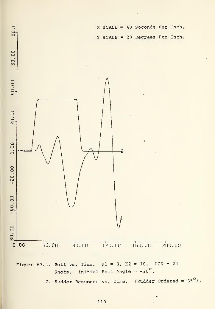
67.1. Roll vs. Time. Kl =3. K2 = 10. UCK = 24 Knots. HOInitial Roll Angle = -20°
.2. Rudder Response vs. Time (Rudder Ordered = 35 )
68.1. Pitch vs. Time. Kl = 3. K2 = 10. UCK = 24 Knots. HIInitial Roll Angle = -20°
.2. Rudder Response vs. Time (Rudder Ordered = 35 )
69.1. Roll vs. Time. Kl =3. K2 = 10. UCK = 24 Knots. 112Initial Roll Angle = -20°
^.2. Rudder Response vs. Time (Rudder Ordered = 35 )
70.1. Sternplane Angle vs. Time. Kl =3. K2 = 10. H^UCK = 24 Knots. Initial Roll Angle = -20°
.2, Rudder Response vs. Time (Rudder Ordered = 35 )
71.1. Sailplane Angle vs. Time. Kl =3. K2 = 10.UCK = 24 Knots. Initial Roll Angle = -20
.2. Rudder Response vs. Time (Rudder Ordered = 35°)
72. Complete Depth-Pitch-Roll Control Block Diagram 116
73.1. Depth vs. Time. Final Result With Roll Error 117
Limiter. Kl = 3. K2 = 10. UCK = 24 Knots.Initial Roll Angle = -20
.2. Rudder Response vs. Time (Rudder Ordered = 35 )
114


Page
74.1. Pitch vs. Time. Final Result With Roll Error Limiter. 118Kl = 3. K2 = 10. UCK = 24 Knots. Initial RollAngle = -20°
^.2. Rudder Response vs. Tine (Rudder Ordered = 35 )
75.1. Roll vs. Time. Final Result With Roll Error Limiter. 119Kl =3. K2 = 10. UCK = 24 Knots. Initial RollAngle = -20°
^.2. Rudder Response vs. Time (Rudder Ordered = 35 )
76.1. Sternplane Angle vs. Time. Final Result With Roll 120Error Limiter. Kl = 3. K2 = 10. UCK = 24 Knots.Initial Roll Angle = -20
^.2. Rudder Response vs. Time (Rudder Ordered = 35 )
77.1. Sailplane Angle vs. Time. Final Result With Roll 121Error Limiter. Kl =3. K2 = 10. UCK = 24 Knots.Initial Roll Angle = -20°
^.2. Rudder Response vs. Time (Rudder Ordered = 35 )
78.1. Depth vs. Time. Final Result With Roll Error 122Limiter. Kl = 3. K2 = 10. UCK = 18 Knots.Initial Roll Angle = -20°
.2. Rudder Response vs. Time (Rudder Ordered = 35 )
79.1. Pitch vs. Time. Final Result With Roll Error Limiter. 123Kl = 3. K2 = 10. UCK = 13 Knots, Initial RollAngle = -20°
,2. Rudder Response vs. Time (Rudder Ordered = 35 )
80.1. Roll vs. Time. Final Result With Roll Error Limiter. 124Kl = 3. K2 = 10. UCK = 18 Knots. Initial RollAngle = -2
.2. Rudder Response vs. Time (Rudder Ordered = 35 )
81.1. Sternplane Angle vs. Time. Final Result With Roll 125Error Limiter. Kl = 3. K2 = 10. UCK = 18 Knots.Initial Roll Angle = -20°
.2. Rudder Response vs. Time (Rudder Ordered = 35 )
82.1. Sailplane Angle vs. Time. Final Result With Roll 126Error Limiter. Kl = 3. K2 = 10. UCK = 18 Knots.Initial Roll Angle = -20°
.2. Rudder Response vs. Time (Rudder Ordered = 35°)
83.1. Depth vs. Time. Final Result With Roll Error Limiter. 127Kl = 3. K2 = 10. UCK = 12 Knots. Initial RollAngle = -20
.2. Rudder Response vs. Time (Rudder Ordered = 35°)
84.1. Pitch vs. Time. Final Result With Roll Error 128Limiter. Kl =3. K2 = 10. UCK = 12 Knots.Initial Roll Angle = -20°
10

.2. Rudder Response vs. Time (Rudder Ordered = 35 )
Page
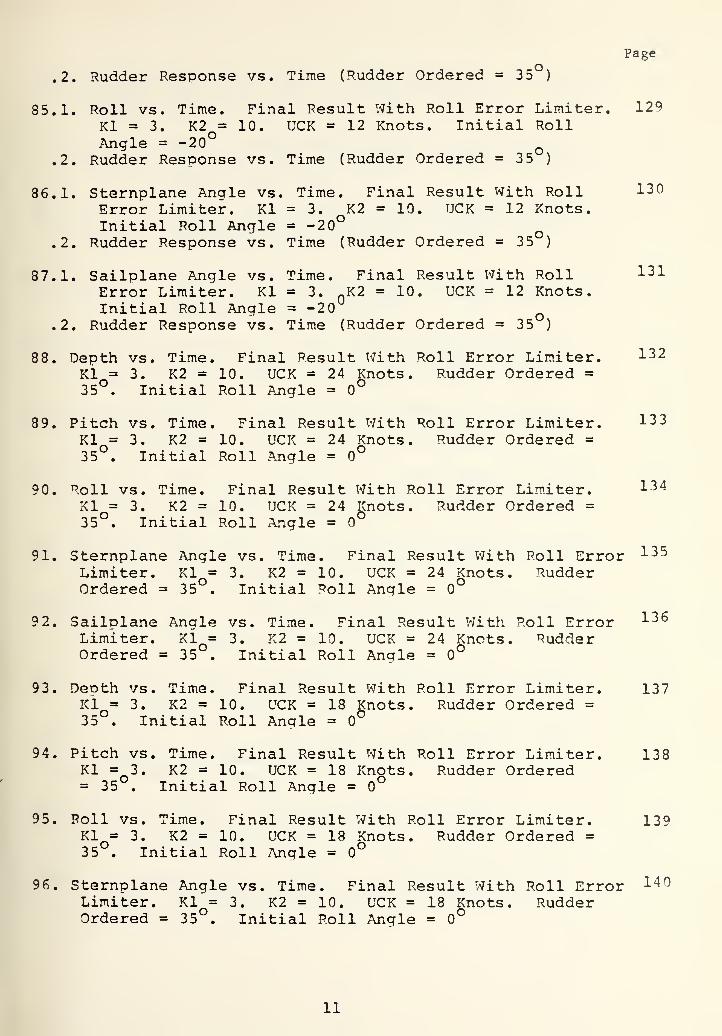
85.1. Roll vs. Time. Final Result With Roll Error Limiter. 129
Kl =3. K2 = 10. UCK = 12 Knots. Initial RollAngle = -20°
^.2. Rudder Response vs. Time (Rudder Ordered = 35 )
86.1. Sternplane Angle vs. Time. Final Result With Roll 130Error Limiter. Kl = 3. K2 = 10. UCK = 12 Knots.Initial Roll Angle = -20°
^.2. Rudder Response vs. Time (Rudder Ordered = 35 )
87.1. Sailplane Angle vs. Time. Final Result With Roll ^31Error Limiter. Kl = 3. ^K2 = 10. UCK = 12 Knots.Initial Roll Angle = -20
^.2. Rudder Response vs. Time (Rudder Ordered = 35 )
88. Depth vs. Time. Final Result With Roll Error Limiter. 1^2
Ki = 3, K2 = 10. UCK = 24 Knots. Rudder Ordered =35°. Initial Roll Angle = 0°
89. Pitch vs. Time. Final Result With Roll Error Limiter. 13 3
Kl = 3. K2 = 10. UCK = 24 Knots. Rudder Ordered =
35 . Initial Roll Angle = 0°
90. Roll vs. Time. Final Result With Roll Error Limiter. 134
XI = 3. K2 = 10. UCK = 24 Knots. Rudder Ordered =
35°. Initial Roll Angle = 0°
91. Sternplane Angle vs. Time. Final Result With Roll Error 135
Limiter. Kl = 3. K2 = 10. UCK = 24 Knots. RudderOrdered = 35 . Initial Roll Angle = 0°
92. Sailplane Angle vs. Time. Final Result With Roll Error ^^^
Limiter. Kl = 3. K2 = 10. UCK = 24 Knots. RudderOrdered = 35 . Initial Roll Angle = 0°
93. Deoth vs. Time. Final Result With Roll Error Limiter. 137Kl = 3. K2 = 10. UCK = 18 Knots. Rudder Ordered =35 . Initial Roll Angle =
94. Pitch vs. Time. Final Result With Roll Error Limiter. 138Kl =3. K2 = 10. UCK = 18 Knots. Rudder Ordered= 35 . Initial Roll Angle = 0°
95. Roll vs. Time. Final Result With Roll Error Limiter. 139Kl^= 3. K2 = 10. UCK = 18 Knots. Rudder Ordered =35 . Initial Roll Angle = 0°
96. Sternplane Angle vs. Time. Final Result With Roll Error 1"^^
Limiter. Kl = 3. K2 = 10. UCK = 18 Knots. RudderOrdered = 35 . Initial Roll Angle = 0°
11

Page
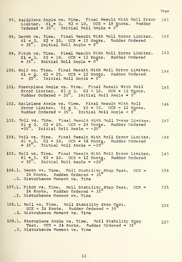
97. Sailplane Angle vs. Time. Final Result With Roll Error 141Limiter. Kl = 3. K2 = 10. UCK = 18 Knots. RudderOrdered = 35°. Initial Roll Angle = 0°
98. Depth vs. Time. Final Result With Roll Error Limiter. 142Kl = 3. K2 = 10. UCK = 12 Knots. Rudder Ordered= 35°. Initial Roll Angle = 0°
99. Pitch vs. Time. Final Result With Roll Error Limiter. 143Kl = 3. K2 = 10. UCK = 12 Knots. Rudder Ordered= 35°. Initial Roll Angle =
100. Roll vs. Time. Final Result With Roll Error Limiter. 2.44Kl =3. K2 = 10. UCK = 12 Knots. Rudder Ordered= 35 . Initial Roll Anale = 0°
101. Sternplane Angle vs. Time. Final Result With Roll I45Error Limiter. Kl =3. K2 = 10. UCK = 12 Knots.Rudder Ordered = 35°. Initial Roll Angle = 0°
102. Sailplane Angle vs. Time. Final Result With Roll 146Error Limiter. Kl =3. K2 = 10. UCK = 12 Knots.Rudder Ordered = 35 , Initial Roll Angle =
103. Roll vs. Time. Final Result With Roll Brror Limiter. 147Kl = 3. K2 = 10. UCK = 24 Knots. Rudder Ordered=35°. Initial Roll Angle = -20°
104. Roll vs. Time. Final Result With Roll Error Limiter. 148Kl =3. K2 = 10. UCK = 18 Knots. Rudder Ordered= 35 . Initial Roll Angle = -20
105. Roll vs. Time. Final Result With Roll Error Limiter. 149Kl =3. K2 = 10. UCK = 12 Knots. Rudder Ordered= 35 . Initial Roll Angle = -20
106.1. Depth vs. Time. Poll Stability Step Test. UCK = 15424 Knots. Rudder Ordered = 35°
.2. Disturbance Moment vs. Time
107.1. Pitch vs. Time. Roll Stability Step Test. UCK = 15524 Knots. Rudder Ordered = 35°
.2. Disturbance Moment vs. Time
108.1. Roll vs. Time. Roll Stability Step Test. X56UCK = 24 Knots. Rudder Ordered = 35
.2. Distrubance Moment vs. Time
109.1, Sternplane Angle vs. Time. Roll Stability Step I57Test. UCK =24 Knots. Rudder Ordered =35°
.2. Disturbance Moment vs. Time
12

Page
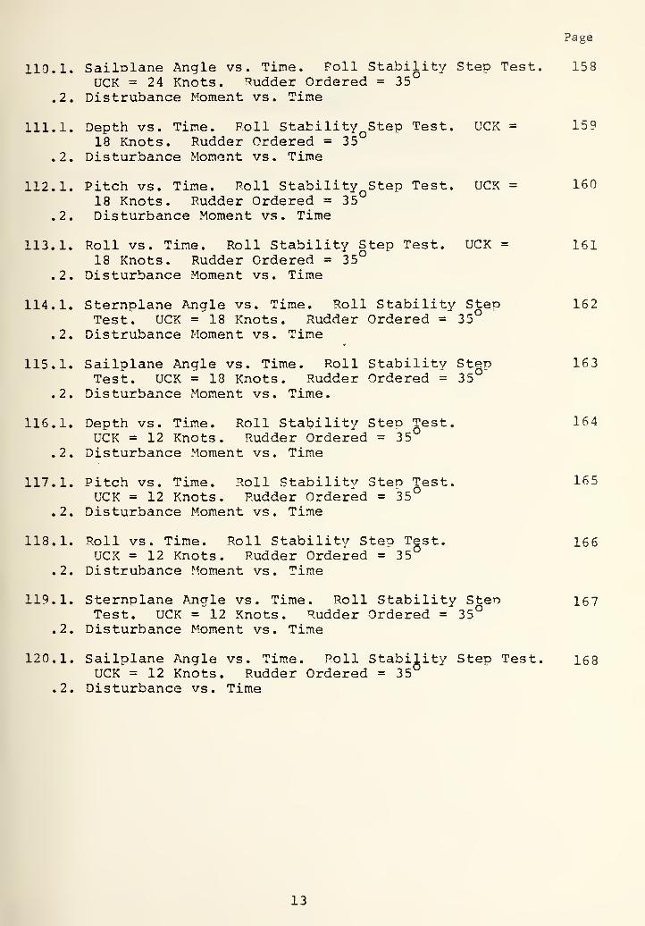
110.1. Sailolane Angle vs. Time. Poll Stability Step Test. 158UCK = 24 Knots. Judder Ordered = 35
.2. Distrubance Moment vs. Time
111.1. Depth vs. Time. Roll Stability^Step Test. UCK = 15918 Knots. Rudder Ordered = 35
.2. Disturbance Moment vs. Time
112.1. Pitch vs. Time. Poll Stability^Step Test. UCK = 16018 Knots. Rudder Ordered = 35
.2. Disturbance Moment vs. Time
113.1. Roll vs. Time. Roll Stability Step Test. UCK = 16118 Knots. Rudder Ordered = 35
.2. Disturbance Moment vs. Time
114.1. Sternplane Angle vs. Time. Roll Stability Step 162Test. UCK = 18 Knots. Rudder Ordered = 35
.2. Distrubance Moment vs. Time
115.1. Sailplane Angle vs. Time. Roll Stability Step 163Test. UCK = 18 Knots. Rudder Ordered = 35
.2. Disturbance Moment vs. Time.
116.1. Depth vs. Time. Roll Stability Steo Jest. 164UCK = 12 Knots. Rudder Ordered = 35
.2. Disturbance Moment vs. Time
117.1. Pitch vs. Time. Roll Stability Step Test. 165UCK = 12 Knots. Rudder Ordered = 35°
.2. Disturbance Moment vs. Time
118.1. Roll vs. Time. Roll Stability Step Test. 166UCK = 12 Knots. Rudder Ordered = 35
.2. Distrubance Moment vs. Time
119.1. Sternplane Angle vs. Time. Roll Stability Sten 167Test. UCK =^12 Knots. Rudder Ordered = 35°
.2. Disturbance Moment vs. Time
120.1. Sailplane Angle vs. Time. Roll Stability Step Test. 168UCK = 12 Knots. Rudder Ordered = 35°
.2. Disturbance vs. Time
13


ACKNOWLEDGEMENTS
The author wishes to express his sincere appreciation
to Professor George J. Thaler for his encouragement and
guidance during the preparation of this thesis.
14


I. INTRODUCTION
The importance of automatic control of Ditch-depth and
roll of a turning submarine has become more obvious with the
improvements of high speed nuclear submarines. This study was
aimed at smoothing the roll of a turning submarine in hiah
speed, which is known as snao roll and causes the basic problem.
Because of coupling between pitch and roll, before attemoting
to smooth the snap roll, controlling of pitch and depth in
high speeds turns was also studied. In this study an auto-
matic course controller was not considered.
The methods and techniques, which can be used to reduce
and smooth the snap roll, can be categorized under two head-
ings. The first concerns changes in the naval architectural
characteristics of the designs, such as increasing GM (meta-
centric height) and reducing sail size. The second category
involves those alternatives which make use of an automatic ship
control system. Rudder sequencing and speed reduction fall
under this classification. Reference 1 investigates the affect
of increasing GM, reducina sail size and speed. In Reference 2,
Stamps designed on automatic roll controller which makes use of
rudder sequencing as a function of aooroach speed and instan-
taneous roll angles.
In recent studies, which were made by Naval Ship Research
and Development Center (NSRDC) , it was proposed to enhance the
control of roll in high soeed turns by using the Fairvater
15

planes differentially deflected so that they can be used to
give a counter moment to reduce the roll. The investigation
of the differentially deflected Fairwater planes effect was
part of the project called "Improved Control For Advanced
Submarines". The project was carried out under Program Element
No. 62754N and Task Area 2F434001. The work unit number was
1-1563-001-74. In Reference 3, estimating the effectiveness
of differentially deflected sailplanes was investigated as a
part of project mentioned above. Reference 3 was the inspira-
tion of this thesis and using differentially deflected sail-
planes for direct control of roll was chosen as the design goal.
16


II. THE N?^TURE OF THE PROBLEM
Turning characteristics of a surfaced submarine, more
or less, looks like those of a surface ship. But the situation
in the submerged position shows big differences. These dif-
ferences are the result of different naval architectural char-
actacteristics. Sail structure can be considered the main dif-
ferences and the main source of roll problems. It is v/ell
knov/n that when a surface ship goes into a turn, it exneriences
an initial inboard roll. After a very short transient it heels
outboard. The reversing of the roll angle is primarily due to
an asymmetric rudder. Since the submarine rudder is generally
well submerged, the surfaced submarine has an outboard roll
angle during both the initial and the steady state phase of a
turn. For a typical submarine, at moderate speed this outboard
roll angle is less than 10 and does not cause any big problem.
If a submerged submarine goes into a high speed turn,
differences from the surfaced behavior are noticed and the
problem becomes three-dimensionalized. In the very first phase
of the turn, the ship has a small lateral velocity v and a
small rotational velocity r. For a starboard turn, at some
point along the centerline, XI, the lateral velocity due to
r, rXl, equals the lateral velocity - v. (For symbols see
Figure 1, 2, and Appendix A). The point, at which these two
velocities are equal to each other, is called the instant
center of turn. At some point, forward of the instant center,
^2, the lateral velocity, -v, gives a velocity component from
17


the starboard side. Along with the ahead velocity component
of the ship, these velocities contribute an ancle of attack
from starboard. At this point, if the submarine has an append-
age (sail) , a lift force is produced on the sail directed to
port. Depending on the sail configuration and the large moment
arm of the sail. This force, directed to the port gives a small
outboard (port) roll. In many submarines this outboard roll can
not be felt.
In the steady state phase the angle of attack shifts to
the other side (port) and results in an inboard roll. But con-
trary to the outboard roll this inboard roll is quite signifi-
cant and at high speeds it can exceed 30*^ which is considered
hazardous to both men and equipments. This inward roll is
called the SNAP roll. In Figure 5, the roll characteristics
of the ship to a constant 35 left rudder angle at 24 knots is
shown. As can be seen, the initial outboard roll (in the
simulation, outboard is the starboard side) is very small,
less than 1 . But the snap roll reaches 37 .
Snap roll is not the only problem that can be faced xvhen
the submarine goes into a turn. Because of the appendage
(which is mainly the sail) , in the submerged position, sub-
marines do not have very good hydrodynamics from this body
structure. When the ship experiences a submerged turn the
sail mainly destroys the waterflow around the hull. As a
result a pressure difference is created between the upoer
portion of the hull and the bottom portion of the hull.
18

And a normal force results directed dov/nward which bodily
pushes the ship down. It is recalled that, in a turn, after
the initial phase, the submarine has an inward roll with the
deflected rudder. Rolling inward, causes this deflected
rudder to act like a sternplane which gives the submarine a
down pitch movement. All of these effects come together and
cause the shio to rise or dive depending on the peculiarity
of its design. As it is stated in Reference 4, "The exact
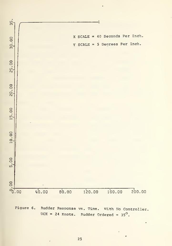
mechanism of this is not well understood". In Figures 3, 4,
and 6, the depth, pitch, and rudder response of the ship, to
a 35 left rudder angle at 24 knots is shown. It is interest-
ing to indicate here that after a long transient period, the
submarine starts to rise with the bow down eventhough it dives
initially. It should be remembered that in this simulation of
the model, no control surface (stern and fairwater olane) was
used. The changes of these characteristics will be seen after
the depth-pitch and roll controller is designed.
The complexity of controlling the turning submarine
mainly comes from the coupling between the roll and pitch.
Since roll and oitch are coupled, to be able to control the
roll, which is our primary concern, pitch control to some ex-
tent must be accomplished. In the following sections a pitch
and depth controller is designed by using only the sternolanes
because of the goal of using the fairv/ater plane as a main
part of the direct roll controller.
19

RUDDER
f > Y-AXI3
(a) INITIAL STAGE OF TURN p - <x
X AXIS
GEOMETRIC V AT RUDDER
+ Y-AXIS
+ X-AXIS
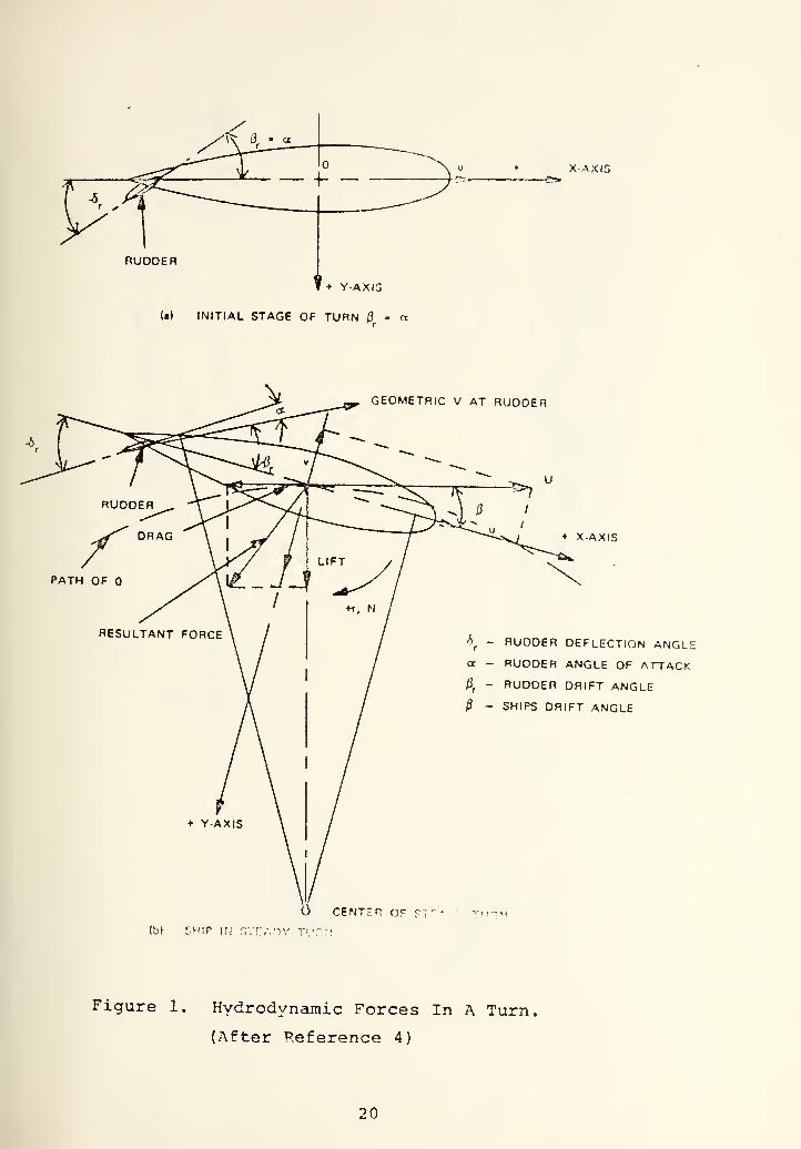
•5^ - RUDDER DEFLECTION ANGLEex - RUDDER ANGLE OF ATTACK
li^ - RUDDER DRIFT ANGLE
- SHIPS DRIFT ANGLE
CENTER OF VT" • T'^'^'i
(b) CHIP iri r,;r:A'-!Y
Figure 1, Hydrodynamic Forces In A Turn
(After Reference 4)
20


w(1)
X<:
C
u(tJ
Ei2
CD
U
•H
ID
uc0)
u<D
4-1
(U
Di
UQ)
-M
<
21


X SCALE = 40 Seconds Per Inch,
Y SCALE = 80 Feet Per Inch.
0.00 40.00 80.00 120.00 160.00 200.00
Figure 3. Death vs. Time. With No Controller
UCK = 24 Knots. Rudder Ordered = 35^.
22


X SCALE =40 Seconds Per Inch,
0.00 40.00 80.00 120.00 ISO. 00 ?00.00
Figure 4. Pitch vs. Time
UCK = 24 Knots
With No Controller.
Rudder Ordered = 35 .
23


X SCALE =40 Seconds Per Inch,
Y SCALE = 8 Degrees Per Inch.
0.00 40.00 80.00 120.00 160.00 200.00
Figure 5. Roll vs. Time. With No Controller.
UCK = 24 Knots. Rudder Ordered = 35^.
24

m.CO
ooo.
OoLD.(\J
OOO.CM
OO
oo
oo
• _
LO'
oo
-1
X SCALE = 40 Seconds Per Inch.
Y SCALE = 5 Degrees Per Inch.
"^'.00 40.00 80.00 120.00 160.00 200.00
Figure 6. Rudder Response vs. Time. V7ith No Controller,UCK = 24 Knots. Rudder Ordered = 35°.
25


III. DIGITAL COMPUTER SIMULATION OF SUBMARINE MOTION
The mathematical model of the totally submerged sub-
marine is represented by the equations of motion which consist
of six equations such that each of them represent the force
and moment equations on and around the three rectangular co-
ordinate axes. These equations were derived by NSRDC in
Reference 5 and for convenience was repeated in Apoendix A.
In this thesis, derivation of these equations was not our
concern. More pronounced knowledge about that can be found in
References 4, 5, and 6.
The equations of motion, which represent the motion of
the totally submerged submarine, in six degree of freedom, con-
sist of Hydrodynamic coefficient, in undimensionalized form
except the m (mass) and I , I , T (three moments of inertia).
In Reference 7, Drurey translated these six equations into the
DSL (digital simulator language) form and originated the com-
puter program which is the mathematical model of the ship.
For the necessity of using the hydrodymanic coefficients in
undimensionalized form, the equations containing 1,1,1,' ^ - x' y ' z
'
both sides are divided by 1 and these three moments of
inertia were used in undimensionalized form. For the same
3reason the equations containing m were divided by 1 .
Since the trim control of the shin was not considered
in this study the ship was assumed in the trimmed condition.
26

For trimming the ship the hydrodynamic coefficient
Z^ and M^ were set to zero. These two hydrodynamic co-
efficients represent the force and moment acting on the ship
when the control surfaces are at zero deflection.
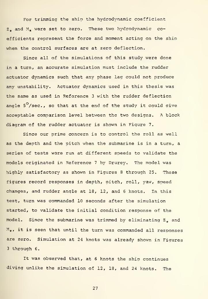
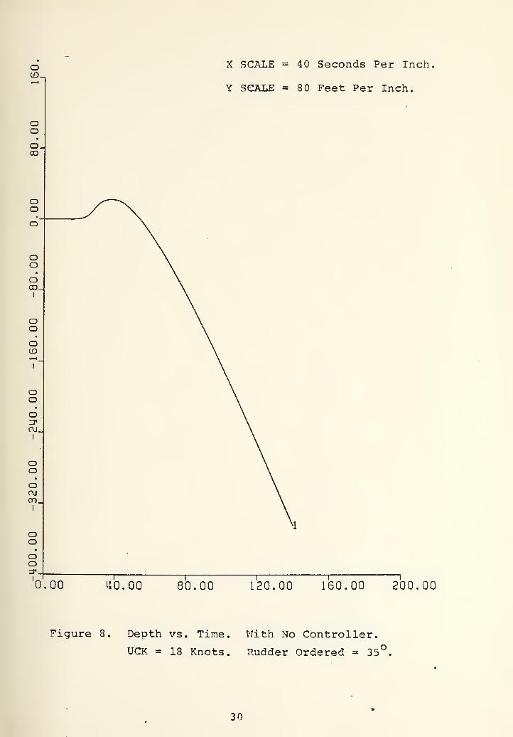
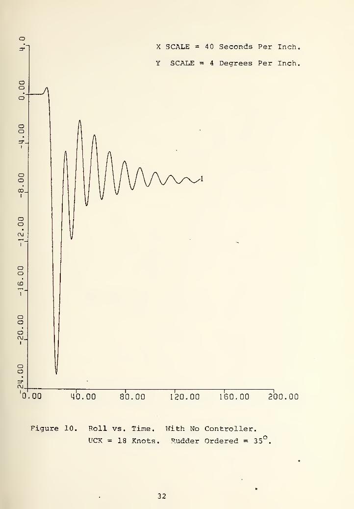
Since all of the simulations of this study were done
in a turn, an accurate simulation must include the rudder
actuator dynamics such that any phase lag could not produce
any unstability. Actuator dynamics used in this thesis v/as
the same as used in Reference 3 with the rudder deflection
angle 5 /sec, so that at the end of the study it could oive
acceptable comparison level between the two designs. A block
diagram of the rudder actuator is shown in Figure 7.
Since our prime concern is to control the roll as well
as the depth and the pitch when the submarine is in a turn, a
series of tests were run at different speeds to validate the
models originated in Reference 7 by Drurey. The model was
highly satisfactory as shown in Figures 8 through 25. These
figures record responses in depth, pitch, roll, yaw, speed
changes, and rudder angle at 18, 12, and 6 knots. In this
test, turn was commanded 10 seconds after the simulation
started, to validate the initial condition response of the
model. Since the submarine was trimmed by eliminating Z^ and
M^, it is seen that until the turn was commanded all responses
are zero. Simulation at 24 knots was already shown in Figures
3 through 6
.
It was observed that, at 6 knots the ship continues
diving unlike the simulation of 12, 18, and 24 knots. The
27


reason for this was that at low speed enough oressure dif-
ference to cause the ship to rise slov/ly could not be created.
After the validation of the model it was decided to pro-
ceed with the designing of the controllers. In the following
sections first, the depth and pitch controller design was stud-
ied. An optimal control scheme such as in Reference 7 was used,
The sternplanes was the control surface of the controller, and
the fairwater plane was saved for use in the roll controller.
28


(Xa
tr-
i< to
1in
I, , . ,, ^^ +
•
1
1\ in1
w \ t
+ \lIT) —^
1 ' 1 i
KCC
uQDCi
1J ^
+jOQD
1 \
inno in+ ro
1
+ inm
1
N. 1
QoDg
o
c
(T
(1)
Di
>^
(U
o
o
«
+)
<
0)
T3s
0)
M
29

oCD.
X SCALE =40 Seconds Per Inch,
Y SCALE =80 Feet Per Inch.
oo
0.00 40.00 80.00 120.00 ISO. 00 200.00
Figure 8. Depth vs. Time. With No Controller.
UCK = 18 Knots. Rudder Ordered = 35*
30


X SCALE = 40 Seconds Per Inch,
Y SCALE = 4 Degrees Per Inch.
0.00 40.00 80.00 120.00 160.00 200.00
Figure 9. Pitch vs. Time. With No Controller.
UCK = 18 Knots. Rudder Ordered = 35°.
31

X SCALE = 40 Seconds Per Inch
Y SCALE = 4 Deqrees Per Inch,
0.0-0 40.00 80.00 120.00 160.00 200.00
Figure 10. Roll vs. Time. With No Controller.
UCK = 18 Knots. Rudder Ordered - 35^
32

X SCALE = 40 Seconds Per Inch.
Y SCALE = 2 Knots Per Inch.
0.00 40.00 80.00 120.00 160.00 200.00
Figure 11. Speed Change vs. Time. With No Controller.
UCK = 18 Knots. Rudder Ordered = 35 .
33

X SCALE = 40 Seconds Per Inch.
Y SCALE = 80 Degrees Per Inch.
0.00 40.00 80.00 120.00 160.00 200.00
Figure 12. Yaw vs. Time. With No Controller.
UCK = 18 Knots. Rudder Ordered = 35°.
34

X SCALE =40 Seconds Per Inch,
Y SCALE = 5 Degrees Per Inch.
^.00 40.00 80.00 120.00 160.00 2^00.00
Figure 13. Rudder Response vs. Time.
UCK = 18 Knots. Rudder Ordered = 35^
35


X SCALE =40 Seconds Per Inch.
Y SCALE = 20 Feet Per Inch.
0.00 40.00 80.00 120.00 160.00 200.00
Figure 14. Depth vs. Time. :^ith No Controller.
UCK = 12 Knots. Rudder Ordered = 35°.
36


X SCALE = 40 Seconds Per Inch,
Y SCALE = 4 Decrees Per Inch.
0.00 40.00 80.00 120.00 160.00 2^00.00
Figure 15. Pitch vs. Time
UCK = 12 Knots
With No Controller.
Rudder Ordered = 35 .
37


X SCALE =40 Seconds Per Inch,
Y SCALE = 2 Degrees Per Inch.
0.00 40.00 80.00 120.00 ISO. 00 200.00
Figure 16. Roll vs. Time. With No Controller.
UCK = 12 Knots. Rudder Ordered = 35^.
38


X SCALE = 40 Seconds Per Inch
Y SCALE = .80 Knots Per Inch.
0.00 40.00 80.00 120.00 160.00 200.00
Figure 17. Speed Change vs. Time. With No Controller.
UCK = 12 Knots. Rudder Ordered = 35°.
39

X SCALE = 40 Seconds Per Inch,
Y SCALE =40 Degrees Per Inch,
0.00 40.00 80.00 120.00 ISO. 00 200.00
Figure 18. Yaw vs. Time. With No Controller.
UCK = 12 Knots. Rudder Ordered = 35°.
40

in.en
oo
•
o.oo
ooLD.(\J
oo
•
o.
Oo
ao
oo
• _
oo
r1
X SCALE =40 Seconds Per Inch,
Y SCALE = 5 Degrees Per Inch.
"^.00 40.00 80.00 120,00 160.00 200.00
Figure 19. Rudder P.esDonse vs. Time. With No Controller
UCK = 12 Knots. Rudder Ordered = 35*^.
41


X SCALE =40 Seconds Per Inch,
Y SCALE = 5 Feet Per Inch.
0.00 40.00 80.00 120.00 160.00 200.00
Figure 20. Depth vs. Time. With No Controller.
UCK = 6 Knots. Rudder Ordered = 35°.
42


X SCALE = 40 Seconds Per Inch,
Y SCALE = 2 Dearees Per Inch.
0.00 40.00 80.00 120.00 160.00 200.00
Figure 21. Pitch vs. Time. VJith No Controller.o
UCK = 6 Knots. Rudder Ordered = 35 .
43


oX SCALE =40 Seconds Per Inch.
Y SCALE = .40 Degrees Per Inch,
0.00 40.00 80.00 120.00 150.00 200.00
Figure 22. Roll vs. Time. With No Controller.
UCK = 6 Knots. Rudder Ordered = 35°.
44

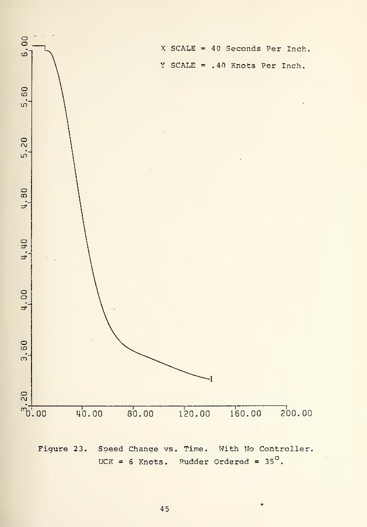
X SCALE =40 Seconds Per Inch,
Y SCALE = .40 Knots Per Inch.
on.
0.00 40.00 80.00 120.00 160.00 200.00
Figure 23. Soeed Change vs. Time. With No Controller.
UCK = 6 Knots. Rudder Ordered = 35°.
45

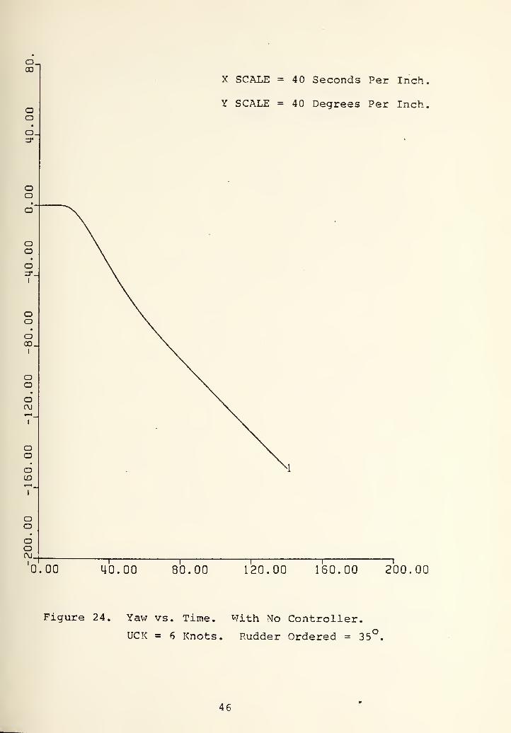
X SCALE = 40 Seconds Per Inch
Y SCALE = 40 Degrees Per Inch,
0.00 40.00 80.00 120.00 160.00 200.00
Figure 24. Yav; vs. Time. With No Controller.
UCK = 6 Knots. Rudder Ordered = 35°.
46


1
X SCALE = 40 Seconds Per Inch.
Y SCALE = 5 Degrees Per Inch.
"^.00 40.00 80.00 120.00 160.00 ?00.00
Figure 25. Rudder Response vs. Time. With No Controller.
UCK = 6 Knots. Rudder Ordered = 35°.
47


IV. AUTOMATIC DEPTH AND PITCH CONTROL
A. OPTIMAL SOLUTION TO THE LINEARIZED SUBMARINE EQUATIONS
The necessity of controlling the depth and pitch of a
turning submarine, as was stated before, stems from the coupling
between the states such that any changes of one of them directly
affects the other one. For this reason, depth and pitch control
to some extent must be accomplished so that it can provide a
good stage for the roll control. There are many ways of con-
trolling the depth and pitch which depend upon the way of using
stern and fairwater control surfaces combination. The scheme
that was used in this thesis was an optimal control way which
was originated by Drureys in Reference 7. To preclude unneces-
sary repetition, only guidelines of the method and the differ-
ences of this study are to be discussed here. More pronounced
knowledge can be found at Reference 7 and 8.
It can be seen in Appendix A that the equations of motion
are nonlinear. To be able to use this set of equations, they
must be linearized. This linearization was done in Reference 7,
and with one control input (sternplane) they can be written in
the form of:
m-Zw -1-Z(5 W
Q
U'Ziv/, UZq
U.M-7/^2 U.Mq/^
W
Q
u zds/.
U Mds/l2
DS
48


If they are put in state variable form
VS/ ^11 ^21
^12 ^22L
w
Q
B
B
11
12
DS
Where
Determ = F (I -M<5) (m-ZC^;) - M'vZc^J
I
(I -M(5)Zw + Z<5MV u/ .
M^'^Zw + (in-Zf^)MW u /2 •
[(Iy-M(5[)Zq + ZdMq] U^ ^^^^
[M^VZq + (m-Zw)Mq7 u^^j^g-
["(I -Md[)Zds + Z^Mdsj u^/ . Dete
hlwZds + (m-Zw) MdsI
u /,2
-"11
^12
A21
A22
Bll
B12
Determ
Determ
!rm
iterm
rm
Determ.
The problem was thought as a linear regulator problem. The
general scheme of linear regulator problem is shown in Figure
26.
The cost function is
J = 4^ I i E'QE + u'^RUj dt
r
E = X-r and r is the reference vector which is
ordered depth
ordered pitch
49

Eh2<
KH:
H «•«
O 4JcmEh Cl,
2Cu
<
£
O
PU
}H
op<d
s
0)
uta
c•H
uo
0)
fHiHOiH
4Jcou^o(d
XI-o
G)
E•H4J
ao
C
rH04
•H
50


As a result
E = X can be written.
Following the Reference 7 and 8
K = -KA+KBR" B"K-Q-a'^K and
-1 TU = -R B KE can be v/ritten.
If the linear equations are auqmented and out in the state
equation form with the definition
E = X =
VI
and U = Ds
T rX.
X.
X'4
Where
-u
A11
12
^21
1
'22
X.
X.
J L^^
B
B
11
12 J
Ds
\~
X2 =
^3
^^4
_
DeDth Rate
Depth
Pitch Rate
Pitch
In this study, in order to make the depth rate a state vari-
able the following trans'Pormation was used
Depth rate = w-u- (3 where w represent the comnonent of
u in the z direction, y represents the nitch angle. In
51


Reference 7 this transformation was originally
Depth Rate = w and the differences between these two .
transformations showed itself in the calculation of K values
which is discussed in the following oages.
Referring to the cost function
Q =
E
A
B
R = C
and
K =
K11
K
K
K
12
13
14
^21 ^31
^22 ^32
^23 ^33
^24 ^34
K
K
K
41
42
K
43
44
The selection of the weiahting factors was a trial and
error orocess. The series of weighting factors deoending upon
the relative severity of the influence of the states to each
other was tested and as a result
E = Depth Error Weighting = 10
D = Pitch Error Weighting = 8000
C = Control Inout Weighting = 100
A = B = was chosen.
After solution of n(n+l) . differential eauations
,
^2
K values associated with the feedback aain was found. It is
observed that steadstate values of X are constant which is a
52

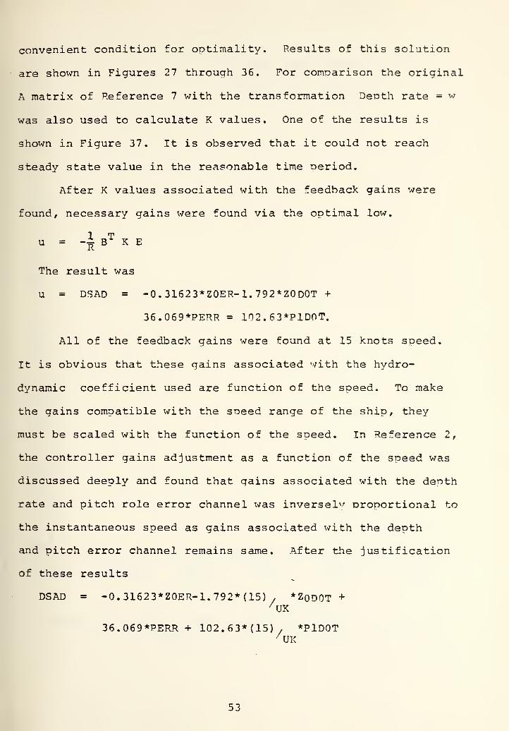
convenient condition for ootimality. Results of this solution
are shown in Figures 27 through 36. For comparison the original
A matrix of Reference 7 with the transformation Depth rate = w
was also used to calculate K values. One of the results is
shown in Figure 37. It is observed that it could not reach
steady state value in the reasonable time period.
After K values associated with the feedback gains were
found, necessary gains were found via the optimal low.
1 Tu = -i B K E
The result was
u = DSAD = -0.31623*Z0ER-1.792*Z0D0T +
36.069*PERR = 102. 63*P1D0T.
All of the feedback gains were found at 15 knots speed.
It is obvious that these gains associated with the hydro-
dynamic coefficient used are function of the speed. To make
the gains compatible with the sneed range of the ship, they
must be scaled with the function of the speed. In Reference 2,
the controller gains adjustment as a function of the speed was
discussed deeply and found that gains associated with the denth
rate and pitch role error channel was inversely proportional to
the instantaneous speed as gains associated with the depth
and pitch error channel remains same. After the justification
of these results
DSAD = -0,31623*Z0ER-1,792*(15) . *ZodOT+
36,069*PERR + 102,63*(15)/ *PlDOT
53


o
oo
CD,
0.00
X SCALE =20 Seconds Per Inch,
Y SCALE = 20 Per Inch.
20.00 u'o.oo 60.00 80.00 Too. 00
Figure 27. Kll vs. Time. UCK = 15 Knots.
D = 8000, A = 0, E = 10, B = 0, C = 100
54


X SCALE = 20 Seconds Per Inch
Y SCALE =40 Per Inch.
-1
"^.00 20.00 40.00 60.00 80.00 100.00
Figure 28. K12 vs. Time. UCK = 15 Knots.
D = 8000, A = 0, E = 10, B = 0, C = 100.
55


X
0.00
X SCALE =20 Seconds Per Inch..
Y SCALE = 800 Per Inch. !
20.00 40.00 60.00 80.00 100.00
Figure 29. K13 vs. Time. UCK = 15 Knots.
D = 8000, A = 0, E = 10, B = 0, C = 100.
56


X SCALE = 20 Seconds Per Inch.
Y SCALE = 2000 Per Inch.
0.00 20.00 40.00 60.00 80.00 ToO.OO
Figure 30. K14 vs. Time. UCK = 15 Knots.
D = 8000, A = 0, E = 10, B = 0, C = 100.
57


X SCALE =20 Seconds Per Inch,
Y SCALE = 200 Per Inch.
'^.OO 20.00 40.00 SO. 00 80.00 100.00
Figure 31. K22 vs. Time. UCK = 15 Knots.
D = 8000, A = 0, E = 10, B = 0, C = 100.
58


OO
O
X
0.00
X SCALE = 20 Seconds Per Inch.
Y SCALE = 4000 Per Inch.
20.00 40.00 60.00 80.00 100.00
Figure 32. K23 vs. Time. UCK = 15 Knots.
D = 8000, A = 0, E = 10, B = 0, C = 100.
59


oo
0.00 20.00
X SCALE = 20 Seconds Per Inch.
Y SCALE = 8000 Per Inch.
40.00 60.00 80.00 100.00
Figure 33. K24 vs. Time. UCK = 15 Knots.
D = 8000, A = 0, E = 10, B = 0, C = 100.
60


X
X SCALE = 20 Seconds Per Inch.
Y SCALE = 50000 Per Inch
"^.00 20.00 40.00 60.00 80.00 ?00.00
Figure 34. K33 vs. Time. UCK = 15 Knots.
D = 8000, A = 0, E = 10, B = 0, C = 100.
61


o
oo
«
oCM.
X SCALE =20 Seconds Per Inch,
Y SCALE = 200000 Per Inch.
X
0.00 20.00 40.00 60.00 80.00 100. OC
Figure 35. K34 vs. Time. UCK = 15 Knots.
D = 8000, A = 0, E = 10, B = 0, C = 100.
62


X
X SCALE = 20 Seconds Per Inch.
Y SCALE = 4 0000 Per Inch.
"^.00 20.00 40.00 60.00 80.00 100.00
Figure 36. K44 vs. Time. UCK = 15 Knots.
D = 8000, A = 0, E = 10, B = 0, C = 100.
63


o X SCALE = 20 Seconds Per Inch,
Y SCALE = 200 Per Inch.
oo
•
oC\J.
0.00 20.00 40.00 SO. 00 80.00 100.00
Figure 37. Kll vs. Time. UCK = 15 Knots.
With Transformation Of Depth Pate = W.
D = 8000, A = 0, E = 10, B = 0, C = 100,
64


•DSAD = -0.31623*Z0ER-26.88/ *ZODOT +
36.069*PERR + 1539.45/ *P1D0T
where UK is the instantaneous soeed (knots).
B. AUTOMATIC DEPTH-PITCH CONTROLLER AND SIMULATION OF THERESULTS
The feedback gains , which are the oatimal solution of
the linearized vertical plane equations must be put into the
general controller schema in which the submarine dynamics are
represented in six degrees of freedom (i.e., non-linear
equations of motion) . Because only the simulation of this can
justify the validity of the solution. The complete modified
version of the Drurey's depth and pitch controller is shown in
Fighre 38. As it is shown the sternplane controller (actuator)
was not designed as a part of the controller and put into the
controller separately with the plane rate 7 /sec. The dynamics
of the actuator is the same as Drurey's and Stamps' controller
used. The same actuator dynamics also was used in the roll
controller which is to be discussed in the following section.
The actuator block diagram is shown in Figure 39. To preclude
stability which occurs as a result of the excessive uses of
the sternplane and avoid use of the control surface with big
deflections the limiter was put into the pitch and depth error
channels. Pitch error limiter was 10 and depth error limiter
was 20 feet and found by a trial and error process.
After the completion of the controller design, various
tests were run to see the effect of the pitch and depth con-
troller on depth, pitch, roll and sternplane responses.
65


wzHPi<<
CQDcn
"
""
y K2 w< J
K J kJEh X CP4 S Oi
H ^ E-^
D y 2:H cXi u
iH+Cfi
iH .H•
e:wiJ
s -"^E^ QOSC S&^g
• K <mE;
u^ ! 1
fvjJ 1
+
s No T 1—-r^'A^.—
i
0)
+J
ccuro-p
^3C<
ac
CO
u
•H
66

en a; 6-
Q C c
Eh
1^HQ
o uI w
wen03
<
W « &HC C Q
Cn Ci:; CmC C C
r
Q qo oen oi faQ O Q
enw
(0
(U
c
0, +J
i-l W(U Vh
4J CJ
<C U-4
gCD
•H(0 fa'
fa Q^cc •
<:
c +J
^ fO
QJ 34J 4J
CO<
M •
en ^-s,
fa Q) uc
iH fD 4J
(U rH (d
t: c D4J
cv^ <
M a+j cn
4J en an3 c3 fd
JJ Eh Mfa
< en
u ^o
<D OJ•H ^U -piH
(D (03 fa<c Gu en •H13 o fC
^r faN-4
•
o>m<U
V4
3D^•Hfa
67


The results of tests at 6, 12, 18, and 24 knots to a constant
35° left rudder angle are shown in Figures 4 through 55.
I^en these results are coirroared with the responses of the ship
with no pitch and depth controller which is shown in Figures
3 through 6 at 24 knots and in Figures 8 through 25 at 18, 12,
and 6 knots. The following coranarisons can be drawn:
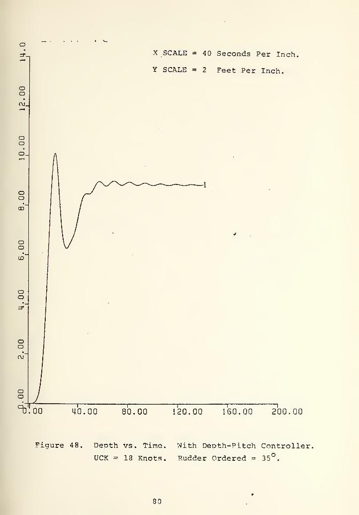
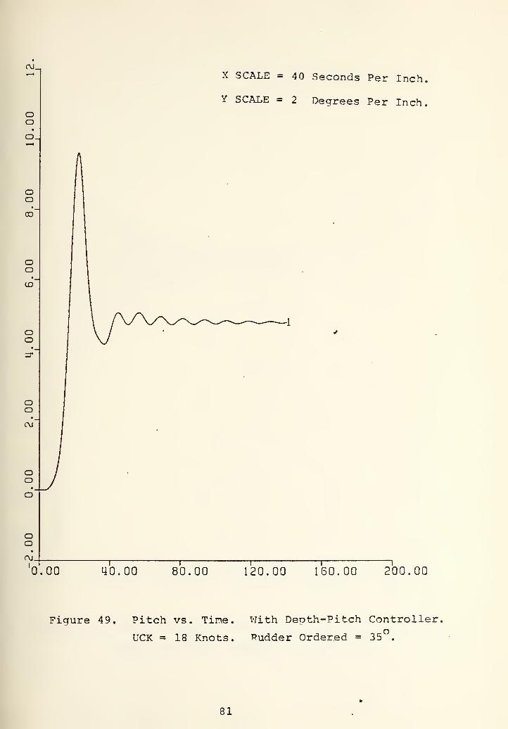
1. At 12 and 18 knots controller kept the ship's depth
and pitch stable after very reasonable transient time.
The steady state pitch and depth are (5,2) - (9.2) feet
at 12 knots and (4.7)*^ - (9) feet at 18 knots.
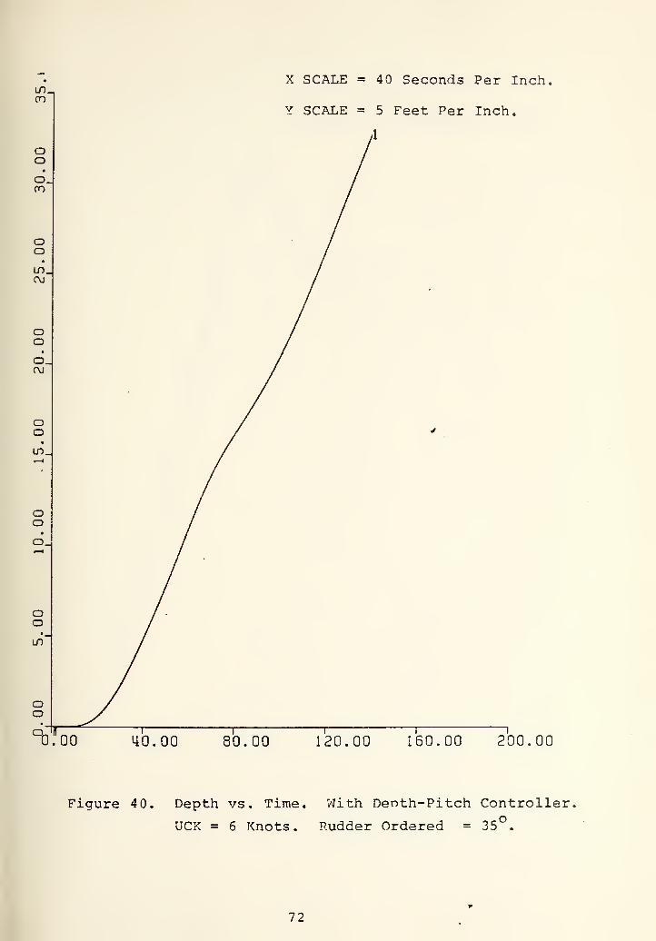
2, At 6 knots, the controller failed to keep the pitch and
depth stable. The ship very slowly kept on losing depth.
The reason was insufficient speed scaling of the feedback
gains and needs for another control surface (Fairwater
planes) . Lack of fairrvater plane control surface in the
depth-pitch controller unabled it to keep shin stable at
low speeds. But in this thesis the primary concern was
to minimize the snao roll which occurs at high speed.
In Reference 2 Stamos collected data which shows the neak
snap roll as a function of the aoproach speed and ordered
rudder angle. This data is repeated at the following
page for convenience (Table I). It is seen that dangerous
snap roll starts occuring at approach speeds cibove 12
knots. For this reason unability of the controller at
low speed was neglected. Because, a control scheme, which
at low speed uses Drury's original depth-pitch controller
(Fairwater plane is part of controller) and at high
68


speed uses this design (^airwater plane is not a part
of depth-pitch controller but is a part of the roll con-
troller) can be designed and switching from one to another
can be achieved.
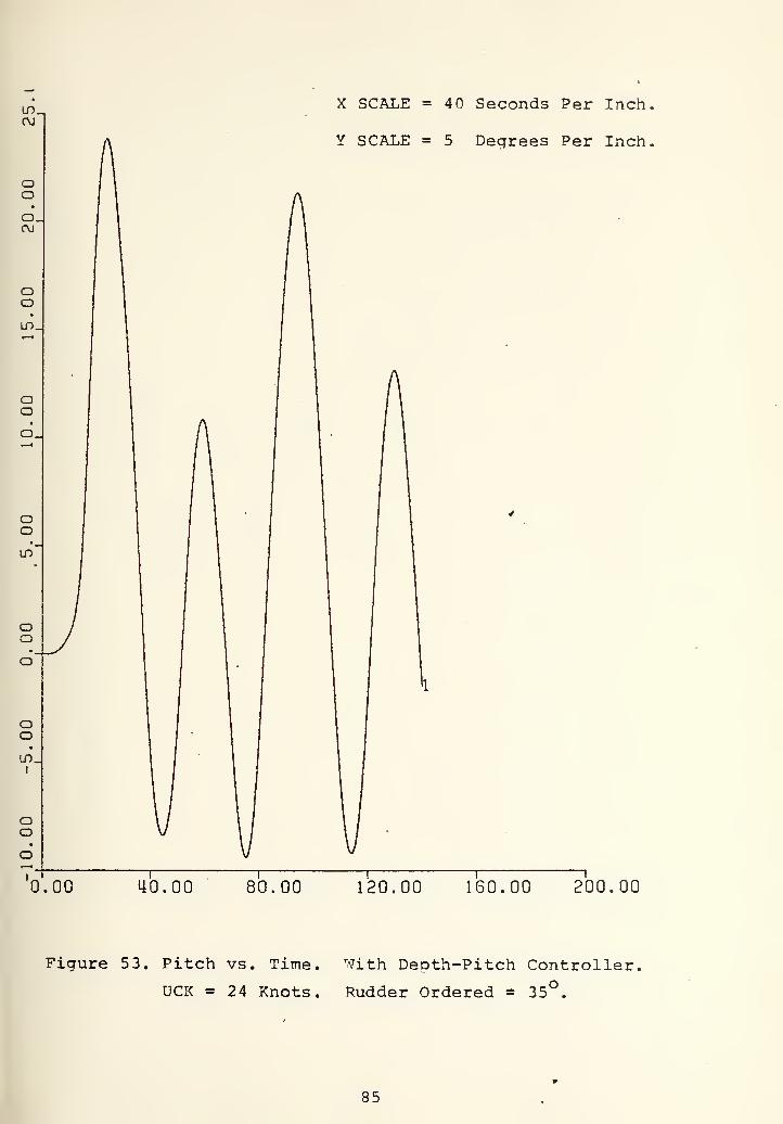
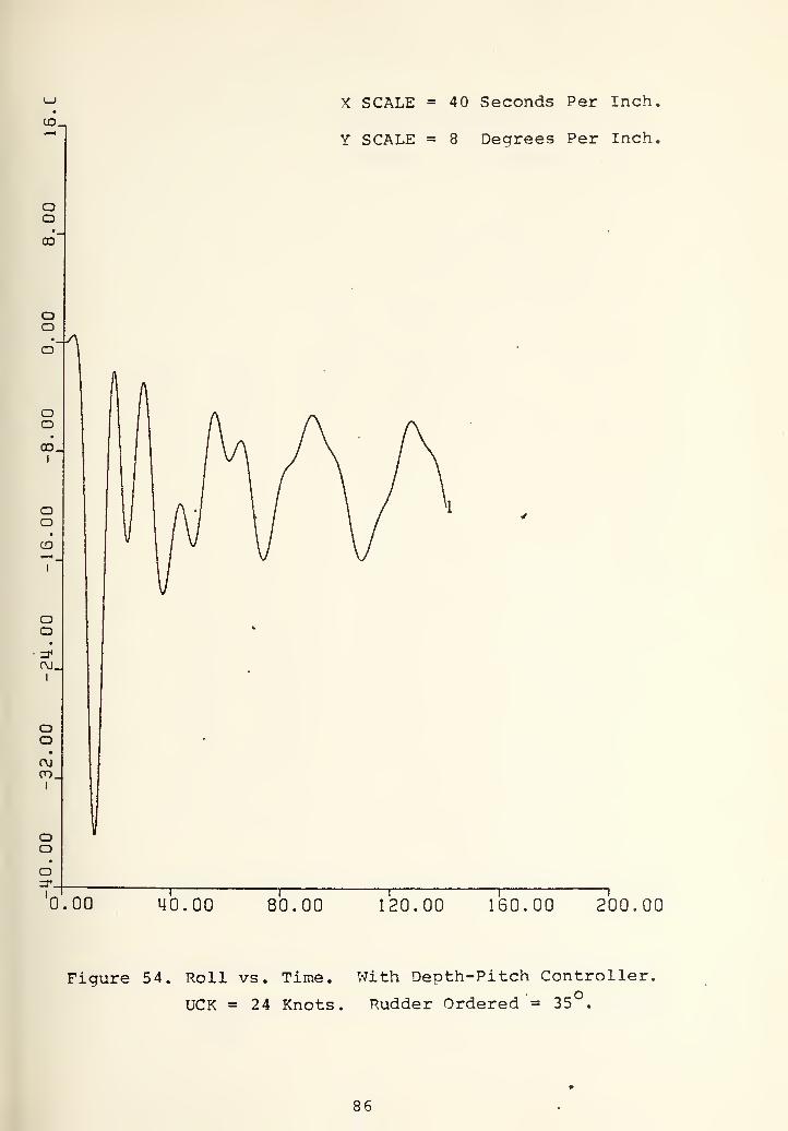
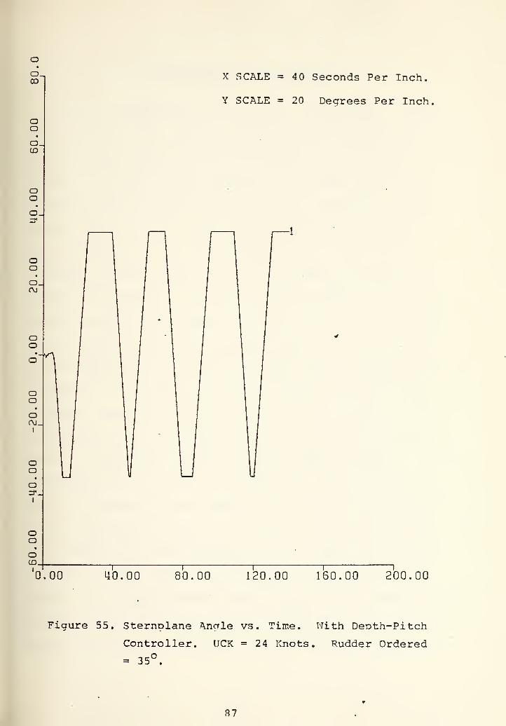
3. At 24 knots the controller again failed to keep the ship
stable. Depth and pitch response went into oscillation
with big amplitudes. Original roll response of the ship
which is shown in Figure 5 was destroyed in the sense of
decreasing amplitudes of roll oscillation. It did not
reach stable value and appeared to be oscillating in the
range of 10 . The reason was the following. The big snap
roll which was around 37 , initially gave very big dis-
turbance and oscillation. With these big disturbances
the controller which uses only the sternolane as a con-
trol surface was unable to do the job. It was thought
that, if there had been any controller which could have
decreased the snap roll (Roll controller) it would have
been able to stabilize the ship in pitch and depth as
well as in the roll response.
Based on the results of these tests, proceeding with the
roll controller design which would make use of fair^vater plane
as a control surface was decided.
69

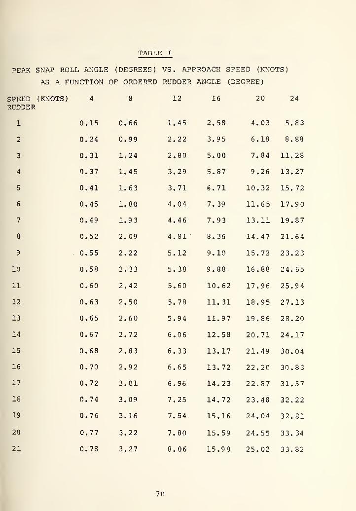
TABLE I
PEiVJC SNAP ROLL ANGLE (DEGREES) VS. APPROACH SPEED (KNOTS)
AS A FUNCTION OF ORDERED RUDDER ANGLE (DEGREE)
12 16 20 24SPEED (KNOTS) 4 8
RUDDER
1 0.15 0.66
2 0.24 0.99
3 0.31 1.24
4 0.37 1.45
5 0.41 1.63
6 0.45 1.80
7 0.49 1.93
8 0.52 2. 09
9 0.55 2.22
10 0.58 2.33
11 0.60 2.42
12 0.63 2.50
13 0.65 2.60
14 0.67 2.72
15 0.68 2.83
16 0.70 2.92
17 0.72 3.01
18 0.74 3.09
19 0.76 3.16
20 0.77 3.22
21 0.78 3.27
1.45 2.58 4.03 5.83
2.22 3.95 6.18 8.88
2.80 5.00 7.84 11.28
3.29 5.87 9.26 13.27
3.71 6.71 10.32 15.72
4.04 7.39 11.65 17.90
4.46 7.93 13.11 19.87
4.81 8.36 14.47 21.64
5.12 9.10 15.72 23.23
5.38 9.88 16.88 24.65
5.60 10.62 17.96 25.94
5.78 11.31 18.95 27.13
5.94 11.97 19.86 28.20
6.06 12.58 20.71 24.17
6.33 13.17 21.49 30.04
6.65 13.72 22.20 30.83
6.96 14.23 22.87 31.57
7.25 14.72 23.48 32.22
7.54 15.16 24.04 32.81
7.80 15.59 24.55 33.34
8.06 15.9 8 25.02 33.82
70

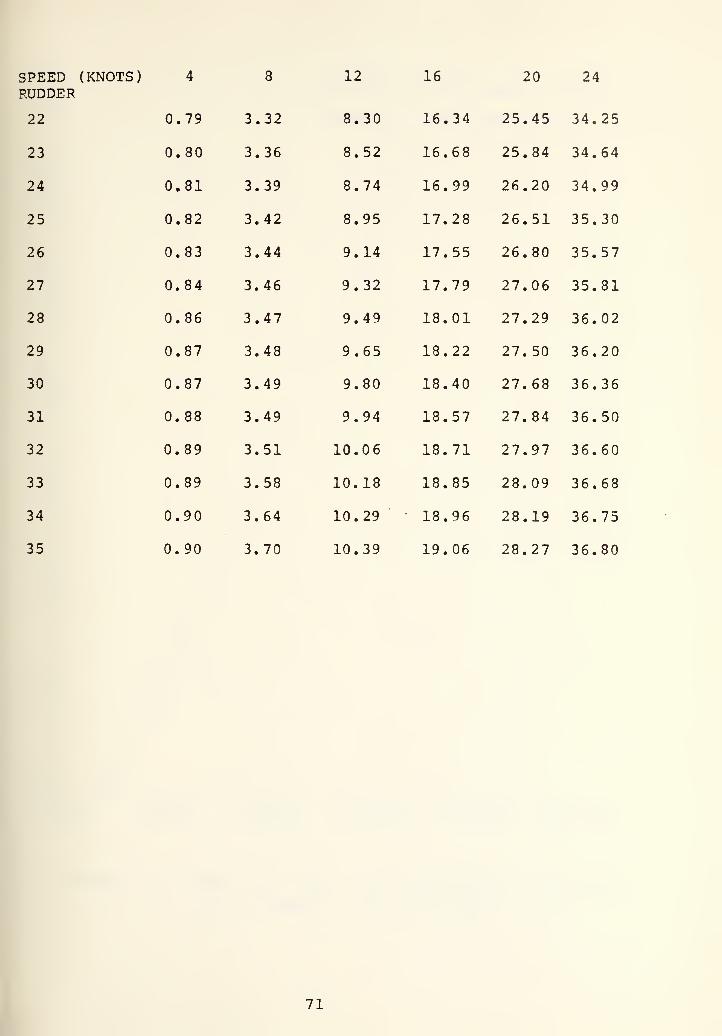
SPEED (KNOTS) 4 8 12 16 20 24RUDDER
22 0.79 3.32 8.30 16.34 25.45 34.25
23 0.80 3.36 8.52 16.68 25.84 34.64
24 0.81 3.39 8.74 16.99 26.20 34.99
25 0.82 3.42 8.95 17.28 26.51 35.30
26 0.83 3.44 9.14 17.55 26.80 35.57
27 0.84 3.46 9.32 17.79 27.06 35.81
28 0.86 3.47 9.49 18.01 27.29 36.02
29 0.87 3.48 9.65 18.22 27.50 36.20
30 0.87 3.49 9.80 18.40 27.68 36.36
31 0.88 3.49 9.94 18.57 27.84 36.50
32 0.89 3.51 10.06 18.71 27.97 36.60
33 0.89 3.58 10.18 18.85 28.09 36.68
34 0.90 3.64 10.29 18.96 28.19 36.75
35 0.90 3.70 10.39 19.06 28.27 36.80
71

X SCALE =40 Seconds Per Inch,
0:00 40.00 80.00 120.00 160.00 200.00
Figure 40. Depth vs. Time. V7ith Denth-Pitch Controller,
UCK = 6 Knots. Rudder Ordered = 35°.
72


X SCALE = 40 Seconds Per Inch,
Y SCALE = 2 Degrees Per Inch
0.00 40.00 80.00 120.00 160.00 ?00.00
Figure 41. Pitch vs. Time. With Depth-Pitch Controller,
UCK = 6 Knots. Rudder Ordered = 35 .
73


oX SCALE = 40 Seconds Per Inch.
Y SCALE = .40 Degrees Per Inch,
0.00 40.00 80.00 120.00 160.00 200.00
Figure 42. Roll vs. Time. With Deoth-Pitch Controller.
UCK = 6 Knots. Rudder Ordered = 35°.
74


X SCALE = 40 Seconds Per Inch,
Y SCALE = 8 Decrees Per Inch,
0.00 40.00 80.00 120.00 ISO. 00 200.00
Figure 43. Sternplane Angle vs. Time. ^^:'ith Depth-Pitch
Controller. UCK = 6 Knots . Rudder Ordered= 35°.
75


X SCALE = 40 Seconds Per Inch,
Y SCALE =2.00 Feet Per Inch.
0.00 40700 80.00 120.00 160.00 200.00
Figure 44. Deoth vs. Tine. With DeDth-Pitch Controller.o
UCK = 12 Knots. Rudder Ordered = 35 .
76


X SCALE = 40 Seconds Per Inch
Y SCALE = 2 Degrees Per Inch,
0.00 40.00 80.00 120.00 160.00 200.00
Figure 45. Pitch vs. Time
UCK = 16 Knots
With Depth-Pitch Controller.
Rudder Ordered = 35°.
77


X SCALE = 40 Seconds Per Inch
Y SCALE = 2 Degrees Per Inch,
0.00 40.00 80.00 120.00 160.00 200.00
Figure 46. Roll vs. Time. With Deoth-Pitch Controller.UCK = 12 Knots. Rudder Ordered = 35°.
78


OJ
ooo.CM
OOCD_
OOOJ.
OOoo'
OO
X SCALE = 4- Seconds Per Inch,
Y SCALE = 4 Degrees Per Inch,
0.00 40.00 80.00 120.00 160.00 200.00
Figure 47. Sternplane Anale vs. Time. With Deoth-Pitch
Controller. UCK = 12 Knots. Rudder Ordered= 35°.
79

X SCALE = 40 Seconds Per Inch.
Y SCALE = 2 Feet Per Inch.
b'loo 40.00 80.00 120.00 160.00 ?00.00
Figure 48. Deoth vs. Time. With Deoth-Pitch Controller,
UCK = 18 Knots. Rudder Ordered = 35°.
80

OJ^X SCALE = 40 Seconds Per Inch,
Y SCALE = 2 Degrees Per Inch,
0.00 40.00 80.00 120.00 160.00 ?00.00
Figure 49. Pitch vs. Time. With Depth-Pitch Controller.
UCK = 18 Knots. Rudder Ordered = 35°.
81

0.00
X SCALE = 40 Seconds Per Inch.
Y SCALE = 4 Dearees Per Inch,
40.00 80.00 120.00 160.00 7oo.oo
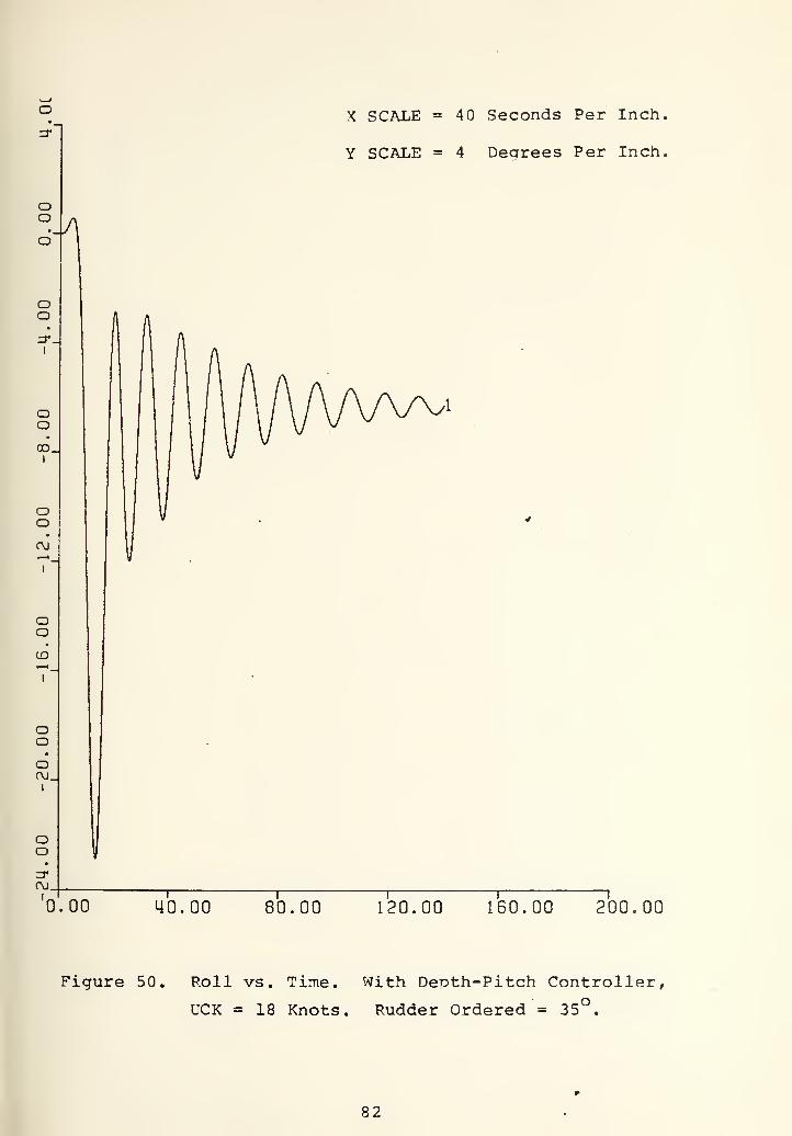
Figure 50. Roll vs. Time. With Depth-Pitch Controller,
UCK = 18 Knots. Rudder Ordered = 35°.
82


X SCALE =40 Seconds Per Inch.
Y SCALE = 8 Degrees Per Inch.^
0.00 40.00 80.00 120.00 160.00 200.00
Figure 51. Sternplane Angle vs. Time. With Depth-Pitch
Controller. UCK = 18 Knots. Rudder Ordered
= 35°.
83


0.00
X SCALE =40 Seconds Per Inch,
Y SCALE = 20 Feet Per Inch.
40.00 80.00 120.00 160.00 ?00.00
Figure 52. Depth vs. Time
UCK =24 Knots
V7ith Denth-Pitch Controller,
Rudder Ordered = 35 ,
84

X SCALE = 40 Seconds Per Inch
Y SCALE = 5 Degrees Per Inch
0.00 40.00 80.00 120.00 160.00 ?00.00
Figure 53. Pitch vs. Time
UCK =24 Knots
''Tith Depth-Pitch Controller.
Rudder Ordered - 35 .
85

0.00
X SCALE =40 Seconds Per Inch,
Y SCALE = 8 Degrees Per Inch,
ub.oo 80.00 120.00 160.00 200.00
Figure 54. Roll vs. Time. With Depth-Pitch Controller.
UCK = 24 Knots. Rudder Ordered = 35°.
86

CO
oo
X SCALE = 40 Seconds Per Inch.
Y SCALE = 20 Degrees Per Inch
0.00 40.00 80.00 120.00 160.00 200.00
Figure 55. Sternplane Anale vs. Time. With Deoth-Pitch
Controller. UCK = 24 Knots. Rudder Ordered
= 35°.
37

V. AUTOMATIC ROLL CONTROLLER
In the introduction of the thesis, the possible choices
of controlling roll was discussed briefly and stated that
fairwater planes v/ere to be used as control fins to control
the roll. The reason that brought uo this idea lies behind
the needs of more control surface than was available in the
present design criteria. Roll control of a high speed sub-
marine has continued to be a problem over the years because
of limited control surface. Control engineers have been re-
stricted using rudder, stern and fairwater plane. All of the
control surface was not meant to control roll. In the present
design criterias stern and fairwater planes are meant to con-
trol the submarine in the vertical olane motion (depth-pitch)
.
The rudder has been used as a part of course controlling of
the ships. Among the three control surfaces, rudder is the
only one that has direct correlation with the submarines roll
angles. In the latest study, which was done by Stamos
/Reference 2/ , it was used to control roll. The concept of
Stamps roll controller was based on the idea of adjusting the
initial rudder angle order as a function of the integral of
error between the allowed maximum roll and actual roll angles.
The initial rudder order was chosen such that the peak roll
expected for a given approach speed would be less than the
maximum allowed roll. The integral of roll error was then
computed and scaled to represent and additive term applied to
88

the initial rudder order. Stamps design didn't give any
structural changes to the present navy submarines design
criteria. In a sense of simplicity it was perfect. But it
prohibited using hard and excessive rudder order which is
highly desirable at some submarines required maneuvering in
certain tactical areas. Since the Stamos design slowed down
the yaw rate and caused the shio to change its course very
slowly, alternative design ways were investigated and using
fairwater plane in the differentially deflected mode was
chosen as a possible improvement.
The concept of roll control by means of fairwater planes
is based on the idea of deflecting the fairvater plane dif-
ferentially such that it can give a roll moment in opposite direc-
tion to the instantaneous roll angle. If the ship has a
roll angle to starboard side, the nlanes are to be deflected
to give a roll moment to portside. The positive sense of this
additional roll moment created by the differentially deflected
sailplanes is the same as of Reference 5. The positive sense
of sailplane deflection angle adopted in this thesis (positive
for port sailplane deflected leading edge up, starboard sail-
plane deflected leading edge-down) is in agreement with that
used for other control surfaces in Reference 5: Positive
when the surfaces are deflected in such a direction as to in-
crease the relevant angle of the submarine about its mass
center. In the case of differentially deflected sailplanes,
the angle is the roll angle and this is defined in Reference 5
to be positive starboard side down.
89


Since, in the present design criteria of navy submarines,
sailplanes are not used in a differentially deflected mode,
standard equations of motion which are developed by NSRDC in
Reference 5, do not have correlative terms which take the
additional moment term, created by the sailplanes into account.
For this reason, before starting to design the roll controller,
this additive moment must be estimated. Once the counter
moment is found it can be placed in the righthand side of the
roll moment equation,
A. ESTIMATING ROLL MOMENT DUE TO DIFFERENTIALLY DEFLECTEDSAILPLANES
In vertical plane motion, the normal force due to the
fairwater planes (sailolanes) is given by the equation of
^N = ^^^^^'2-^ -Sb
Where 0=2L = ship length in feet
U = forward speed
Z Cuv : hydrodynamic coefficient associated with the
sailplane deflection (in conventional mode - right and left
side moves together in the same direction)
.
Db= Deflection of the sailplane in radians.
After setting 9 =2 the normal force equation becomes
F,^ = L2.u2.z9|3.Sb
This force is due to both sides of the sailplanes. The
force due to one side of the plane pair is half of the total
90


force that is j L 'U * Z^^^Q If both sides of the planes
are deflected by the same amount and in onposite direction
compared to each other, this configuration creates a moment
associated with the moment arm between these opposite forces.
This is shown in Figure 56. Total amount of the moment due to
sailplanes can be written
2*1*^"*'-^ *^ShD 'Sb- (moment arm)
M = L "U •Zrj'Sb. (moment arm)'i-
= L 'U • Ob» ^^Sb "'foment arm) .^
if this momemt term is placed in the right side of the
equation of motion about the body axis system X-Axis (roll
axis) , the complete equation takes the form of
I^P + (I^-lY)qr = L^ /"Kp* p + Kqr'qr + Kr ' r + K^.^/ P|Pl_7
+ l"^ /"Kp'up + Kr'ur + K^'v"*"
^wp'^'^-^
+ L^ /"K^'u^ + K^'uv + K^j^^'v|(v2 4. w^)\^^J
+ L^ K_ '^/w + L"^*U^*KC_-Srvw o\
3 2 C+ L 'U • (Zr.* moment arm) ,_ 'O
+ B_^ Sin Cos
In this last form Q^^is replaced by 5^p to indicate that the
fairwater plane is to be used in differentially deflected mode
( ^u^represents deflection anale of fairwater nlane in con-
ventional usage. Both right and left sides move in the same
direction)
91

-1-
STARBOARD
-2-
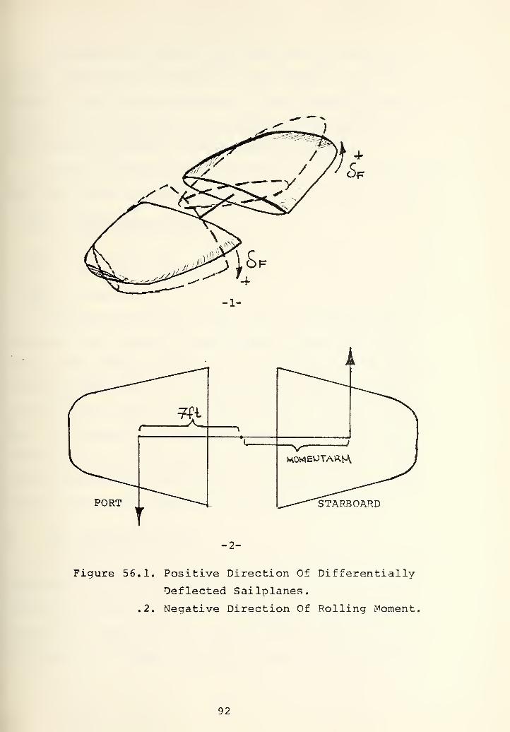
Figure 56.1. Positive Direction Of Differentially
Deflected Sailplanes.
,2. Negative Direction Of Rolling Moment,
92


The moment arm used in this study v/as estimated by in-
voking the data from Reference 6 that belongs to the un-
classified fictitious submarine. In the reasonable prooortion
to the length of the ship, the moment arm was chosen as 7 ft.
and, according the data, it was thought acceptable.
If the new hydrodynamic coefficient is defined associated
with the fairvrater planes in differentially deflected node
ZC„ _ (Z^lQ* moment arm)
Li
^(Sf = (0.00558 X 1^251 75
Yf ^ 0.0015517.
After the estimation of zr^, as a hydrodynamic co-
efficient, it is placed in the modified equation discussed
above. After these modifications, in the equations of motion
all of the term which is a function of the 5lo ^^^^1^^^^® ^®~
flection in the conventional mode) was set to zero by defining
0^= 0. As result, the equation of motion about the X-axis
(roll axis) has correlative term between the fair^«'ater plane
and roll angle of the ship so that this additive moment term
can be used to give feedback to smooth the snap roll.
B. ROLL CONTROLLER DESIGN
In contrast to the denth and pitch controller, the roll
controller was designed by using the nonlinear equations of
motion and linearizing was not attempted. In the previous
section, the modification of the roll moment equation due to
the imposition of moment term which stems from the fairwater
93

planes deflection was discussed. All through the roll con-
troller design this modified version of the equations was
used. The reason that led to using six nonlinear equations
was such that linearizing of this equations in six dereee of
freedom was found difficult because of the terms couoled with
each other and mainly was thought that from the outDut of the
system dynamics the roll angle and the roll rate (p) could
give enough feedback information to accomplish the compensation,
The principles for designing the roll controller were
simple. If the ship has a positive roll angle (starboard)
the fairwater plane is to be deflected so that it can give
negative roll moment, i.e., starboard sailplane is to be de-
flected leading edge up while port sailplane is deflected
leading edge down or vice versa. As long as the ship has a
roll angle this would cause the fairwater plane deflection by
way of the feedback channel used. In the desian it was assumed
that, the fainvater planes actuater was capable of givina e-
qual amounts of deflection command in opposite directions to
both starboard and port sailplanes. Since the design was to
invoke extensive simulation study (since nonlinear equations
were used) in determination of the feedback parameters, the
first basic controller attempt was the proportional controller
because of its simplicity to design and implement. The pro-
portional controller is shown in Figure 5 7.1. Referring to
the figure, if the submarine has a roll angle this would give
the position feedback to force the svstem to reach zero roll
94


SUBMARINE<y FAIRWATERPLANES
ACTUATOR
£f ROLL
li i
DF0RDERED=-K1*R0LL
Kl
-1-
FAIRWATERPLANES
ACTUATOR
S
DF0RDERED=-K1*R0LL-K2*P
SUBMARINE
K2
1
S
ROLL
Kl
-2-
Figure 57.1. Position Feedback Controller.
.2, Position J^nd Velocity Feedback Controller,
95


angle position. Determination of Kl (proportional constant)
was a trial and error process. Even though position feed-
back alone gave big inrorovement in the system dynamics, as is
to be discussed in the following pages, it failed to stabil-
ize the system in some ooerating conditions that are consider-
ed very likely to be faced. This leads to the comoensation
of the system by velocity feedback and other modifications
(Limiter in the position feedback channel) . In the following
pages the design procedure which uses extensive computer sim-
ulation is discussed from the simplest case of proportional
controller to the last modification that stabilized the system
in various operating conditions and over a wide range of sneeds
1, Proportional Controller
The first attempt to control the roll was to design
a proportional controller as is shown in Figure 57.1. Refer-
ring to the figure, it is seen that ordered fairwater plane
deflection is a function of the roll angle and the proportional
constant Kl. Such that
ORDERED FAIRWATER DEFLECTION = DFOD = -Kl*ROLL
Since the reference signal is zero the system always looks for
zero roll angle. Ordered fairwater deflection as an input to
the fairwater planes actuator causes deflected planes at the
output due to the actuator dynemiics. Actuator dynamics were
the same as those of the sternplanes actuator shown in Figure
39. With the counter roll moment created differentially de-
flected fairwater planes, system dynamics try to decrease the
roll angle.
96


Determination of Kl was a trial and error process.
The stability range was 1 through 4. 3y inspection of the
results of computer simulations, Kl = 3 was chosen as a best
choice in the sense of snap roll and steady state value of
the roll responses. With the determined Kl = 3 value the
system was tested at 24 knots aoproach sneed to a 35 rudder
command and the results are shown in Figures 58 through 62.
Before analyzing the results it is instructive to indicate
here that all through the design procedure the worst condition
that could happen was always taken into account. For this
reason the controller was designed at 24 knots base speed and
to a 35 constant rudder angle which could give the worst snap
roll in the range of soeed of interest. 3y lookina at the
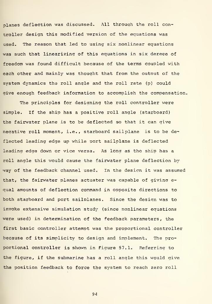
Figures 58 through 62, the following results can be summarized:
1. As was predicted, the snap roll decreased to almost
4 .6 from 37 and roll response reached a steady state
value of 3 ,5. In Figures 52, 53, and 5 4 it was shown
that before implementation of the roll controller the
system was unstable to an identical test. Adding the roll
controller made the system stable at high speed. In depth
and pitch responses great imnrovement has been made.
Steady state values of the depth and pitch were almost
8 feet and 4 .5 which were acceptable. While this deoth,
pitch and roll control improvement has been obtained, the
stern and sailnlane was used moderately such that they
didn't reach any saturation (± 35°).
97


0J_
oo
X SCALE = 40 Seconds Per Inch,
Y SCALE = 2 Feet Per Inch.
0.00 40.00 80.00 120.00 160.00 ?00.00
.Figure 58. Depth vs. Time.
Rudder Ordered
Kl = 3. UCK = 24 Knots.
= 35 . Initial Roll Angle =- oO
98


oCD
in'
ooo
oo
o
en'
o
oCD
ooo
oo
X SCALE =40 Seconds Per Inch.
Y SCALE = .80 Degrees Per Inch,
"^"OO 40.00 80.00 120.00 160.00 ?00.00
Figure 59. Pitch vs. Time.
Rudcier Ordered
= 0°.
Kl = 3. UCK = 24 Knots.
= 35 . Initial Roll Angle
99


ooo
0.00
X SCALE = 40 Seconds Per Inch,
Y SCALE = .80 Degrees Per Inch,
40.00 80.00 120.00 150.00 ?00.00
Figure 60, Roll vs. Time.
Ordered = 35 ,
Kl = 3. UCK =24 Knots. Rudder
Initial Roll Angle = 0^.
100


X SCALE =40 Seconds Per Inch.
Y. SCALE = .40 Degrees Per Inch,
0.00 40.00 80.00 120.00 160.00 200.00
Figure 61. Sternplane Angle vs. Time,
24 Knots. Rudder Ordered
Roll Angle = 0°.
Kl = 3. UCK =
= 35 . Initial
101

CM
OO
•
(£)J
X SCALE =40 Seconds Per Inch,
Y SCALE = 4 Degrees Per Inch,
0.00 40.00 80.00 120.00 ISO. 00 200.00
Figure 62. Sailplane Angle vs. Time. Kl = 3. UCK =
24 Knots. Rudder Ordered = 35 . Initial
Roll Angle = 0°.
102


X SCALE =40 Seconds Per Inch,
Y SCALE = 40 Feet Per Inch.
0.00 40.00 80.00 120.00 150.00 200.00
Figure 6 3. Depth vs. Time. Kl = 3. UCK =24 Knots.
Rudder Ordered = 35 . Initial Roll Angle
= -5°.
103

X SCALE =40 Seconds Per Inch
Y SCALE = 8 Degrees Per Inch,
0.00 40.00 80.00 120.00 160.00 200.00
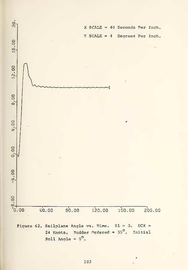
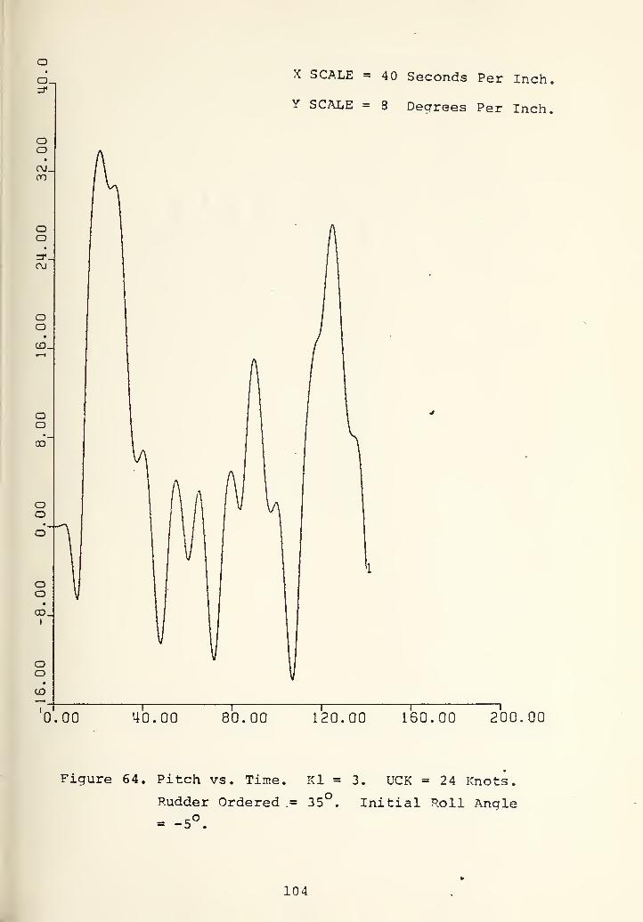
Figure 64. Pitch vs. Time.
Rudder Ordered
= -5°.
Kl = 3. UCK = 24 Knots.
= 35 . Initial Roll Anqle
104


X SCALE = 40 Seconds Per Inch.
Y SCALE = 20 Degrees Per Inch.
0.00 40.00 80.00 120.00 160.00 200.00
Figure 65. Poll vs. Time.
Rudder Ordered = 35
= -5°.
Kl = 3.
oUCK =24 Knots.
Initial Roll Angle
105


2. Investigation of the roll response in Figure 60 lead
to further study. In the steady state value of the roll,
the oscillation with almost fixed amplitude and fre-
quency was observed. The amplitude was around Otl. As
a first guess, the oscillation was thought to be a stable
limitcycle. To exDOse the problem the system was tested
with initial roll response (5 inboard roll angle) at 24
knots to a 35 constant rudder angle. Figures 63, 64,
and 6 5 record the depth, pitch, and roll responses. The
system became unstable. The system failed to compensate
itself when it was commanded to turn with the 35 rudder
deflection and 5 initial inboard roll. Any submarine
maneuvering in the tactical area may experience a turn
with initial roll angle. Disturbances from the heavy sea
state might cause the submarine to roll eventhough it is
in a straight course. If the submarine is commanded to
turn at this moment, it was shown that its control is lost.
That is why the situation was thought unacceptable and com-
pensation of the system was attempted. It was thought that
the reason for the failure was lack of enough feedback in-
formation and compensation of the system with velocity
feedback was attempted.
The following section describes the modification and improve-
ment obtained.
2. Compensation Of The System With Velocity Feedback
The modified controller block diagram is shown in
Figure 57.2., and DFOD = -Kl*R0LL-K2*P.
106


It was felt that the velocity feedback should give to the
system better dampina and better stability characteristics.
Determination of the K2 value was again a trial and error
process and the stability range was found to be 1 to 15 by
computer simulation. By inspection of the results of the
tests with different K2 values, K2 = 10 was considered the
best choice in the sense of snap roll (max roll) and steady
state value of the roll responses. Since the reason for intro-
dncincr velocity feedback was instability in the presence
of an initial roll angle, tests with exaggerated initial roll
(20 inboard) v;ere made. It was oreviously denoted that the
ship has almost 37° snap roll at 24 knots to a 35 rudder
command. To force the ship to turn with a hard rudder command
when it already has a very serious initial roll angle was
thought a good example of the capability to control the shin
in three dimensions. In fact, any submarine cruising in a
straight course is unlikely to face this much roll angle from
heavy seastate. In Figure 66 the result of this test is shown.
Before the implementation of the velocity feedback the system
was unstable to a turn command with initial 5 roll angle.
And now it is stable even with 20 initial inboard roll. The
result was such that steady state roll angle was almost 4 .5
and before reaching steady value on oscillation v;ith decreasing
amplitude was observed. In all of the aforementioned tests,
the ship response was investigated to a steady 35 rudder
command. The rudder was commanded to a 35 deflection at the
beginning of the simulation and after reachina 35 it was not
107


oo
oo
oo=r.
I
oooo.
I
ooOJ
ooCD
oooOj_|
I
oo
OJ.
X SCALE =40 Seconds Per Inch,
Y SCALE = 4 Dearees Per Inch,
0.00 40.00 80.00 120.00 160.00 200.00
Figure 66. Roll vs. Time. Kl = 3, K2 = 10. UCK = 24 Knots,
Rudder Ordered = 35°. Initial Roll Angle = -20
108


changed to any other coimnand. But any submarine maneuvering
in tactical areas can experience successive rudder commands
in opposite directions. For this reason the test, in which
othe rudder deflection was commanded to 35 in the time inter-
val of 20 to 80 seconds was required. Figures 67 through 71
record the depth, pitch, roll, sternolane and sailolane de-
flection. In this test the initial roll angle was again 20
inboard. The result was unstable. Inspection of these
figures reveals a very important reason of the failure. Curve
number 2 in these figures represents the rudder response. But
since in the vertical axis the automatic scaling was used
associated with the output responses of interest, in some
figures the rudder response in the time interval of 20 to 80
seconds was seen less than 35 . For this reason, to overcome
misinterpretation, curve number 2 should be interpreted as the
time interval where rudder deflection was 35 . By inspection
of the figures 67 and 68 its seen that the depth and oitch re-
sponse are almost unchaged. The very small changes are due to
the roll oscilation which stems from the initial roll angle.
In Figure 70 it is shown that in the time interval of - 20
seconds the sternplanes oscillate with very small amtDlitudes
to compensate these depth and pitch changes. But in the same
time interval (0-20 seconds) the sailplanes oscillate with
big amplitudes to overcome the roll oscillation started with
the initial 20 inboard roll angle (Figure 71) , Because of
the roll controller, the initial roll angle has more effect
109

o.00
oo
•
o.CD
X SCALE = 40 Seconds Per Inch,
Y SCALE = 20 Decrees Per Inch,
0.00 40.00 80.00 120.00 160.00 200.00
Figure 67.1. Roll vs. Time. Kl = 3, K2 = 10. UCK = 24
Knots. Initial Roll Angle = -20 .
.2. Rudder Response vs. Time. (Rudder Ordered = 35 )
110


X SCALE = 40 Seconds Per Inch
Y SCALE (1) = 8 Degrees Per Inch
0.00 40.00 80.00 120.00 160.00 200.00
Figure 68.1. Pitch vs. Time. Kl = 3, K2 = 10. UCK =
24 Knots. Initial Roll Anale = -20°.
.2. Rudder Response vs. Tine. (Rudder Ordered
= 35°).
Ill


LD-
OOo_
OOm'
oo
ooin.
(
ooo
ooLO
Ooo
231
'o.oo
X SCALE = 40 Seconds Per Inch.
Y SCALE (1) = 5 Dearees Per Inch,
ll
40.00 80.00 120.00 160.00 200.00
Figure 69.1. Roll vs. Time. Kl = 3, K2 = 10. UCK =
24 Knots. Initial Roll Anale = -20°.
.2. Rudder Response vs. Time (Rudder Ordered
= 35°.)
112


o.oo
oo
•
o.CD
0.00
X SCALE = 40 Seconds Per Inch.
Y SCALE = 20 Degrees Per Inch.
40.00 80.00 120.00 160.00 200.00
Figure 70.1. Sternplane Angle vs. Time. Kl = 3, K2 = 10.
UCK = 24 Knots. Initial Roll Angle = -20°.
.2. Rudder Response vs. Time (Rudder Ordered =
35°).
113


X SCALE = 40 Seconds Per Inch,
Y SCALE = 8 Degrees Per Inch.
.00 Lio.oo 80.00 120.00 160.00 200,00
Figure 71.1. Sailplane Angle vs. Time. Kl = 3, K2 = 10.
UCK = 24 Knots. Initial Roll Angle = -20°.
.2. Rudder Resoonse vs. Time (Rudder Ordered =
35°).
114


on the sailplanes than on the sternplanes. In the time inter-
val of - 20 seconds of Figure 69 the roll oscillation started
with the initial roll angle is seen. Since the direct effect
of the roll angle on the sailplane deflection, this initial
roll oscillation causes the sailplane to oscillate and this
oscillation causes initial roll oscillation not to be damned
out. As this is going on, at time equal to 20 seconds the
rudder was commanded to 35 full deflection and this gives more
unstability. After analyzing this and previous results the
following conclusion has been reached. Since the roll angle
was directly fedback via Kl, the sudden and big roll response
changes cause the sailplane to oscillate with big amplitudes
and this leads to unstability. To overcome this difficulty a
limiter was placed in the roll error feedback channel with the
magnitude of ±5 (The same reason had lead to the placing
depth and oitch error limiter in the depth and pitch controller
design as was discussed in Section IV.B.). After this last
modification the system was tested under various conditions
which are to be discussed below. The complete controller block
diagram with the depth and pitch controller is shown in Figure
72. By inspection, the simulation results of the last version
of the controller can be sumarized as follows:
1. In Figures 73 through 87 the depth, pitch, roll, stern-
plane and sailplanes responses at 24, 18, and 12 knots to
35 rudder command in the time interval of 20 - 80 seconds)
with the initial 20° inboard roll angle are shown. The
115

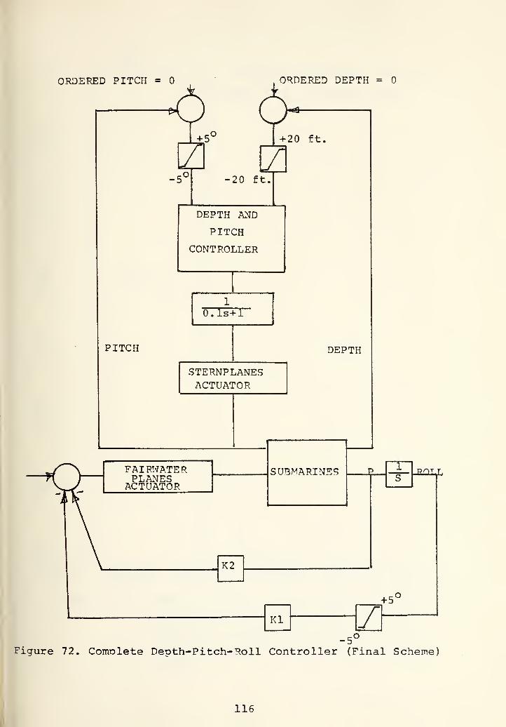
ORDERED PITCH =
+ 5
-5^
ORDERED DEPTH =
+ 20 ft,
-20 ft.
DEPTH AND
PITCH
CONTROLLER
1
O.ls+1
PITCH DEPTH
STERNPLANESACTUATOR
FAIRWATERPLANESACTUATOR
SUBMARINES
K2
J?OTJ,
Kl
+5'
/-5"
Figure 72. Comnlete Depth-Pitch- Roll Controller (Final Scheme)
116


X SCALE =40 Seconds Per Inch,
Y SCALE (1) = 2 Feet Per Inch.
0.00 40.00 80.00 120.00 160.00 200.00
Figure 73.1. Deoth vs. Time. Final Result With Roll
.2.
Error Limiter. Kl = 3, K2 = 10. UCK =
24 Knots. Initial Roll Angle = -20°.
Rudder Resoonse vs. Time. (Rudder Ordered
= 35°).
117


X SCALE = 40 Seconds Per Inch.
Y SCALE (1) = .80 Degrees Per Inch,
o.0.00 40.00 80.00 120.00 160.00 200.00
Figure 74.1. Pitch vs. Time. Final Result With i^oll Error
Limiter. Kl = 3, K2 = 10. UCK = 24 Knots.
Initial Roll Angle = -20°.
.2. Rudder Response vs. Time (Rudder Ordered =
35°).
118

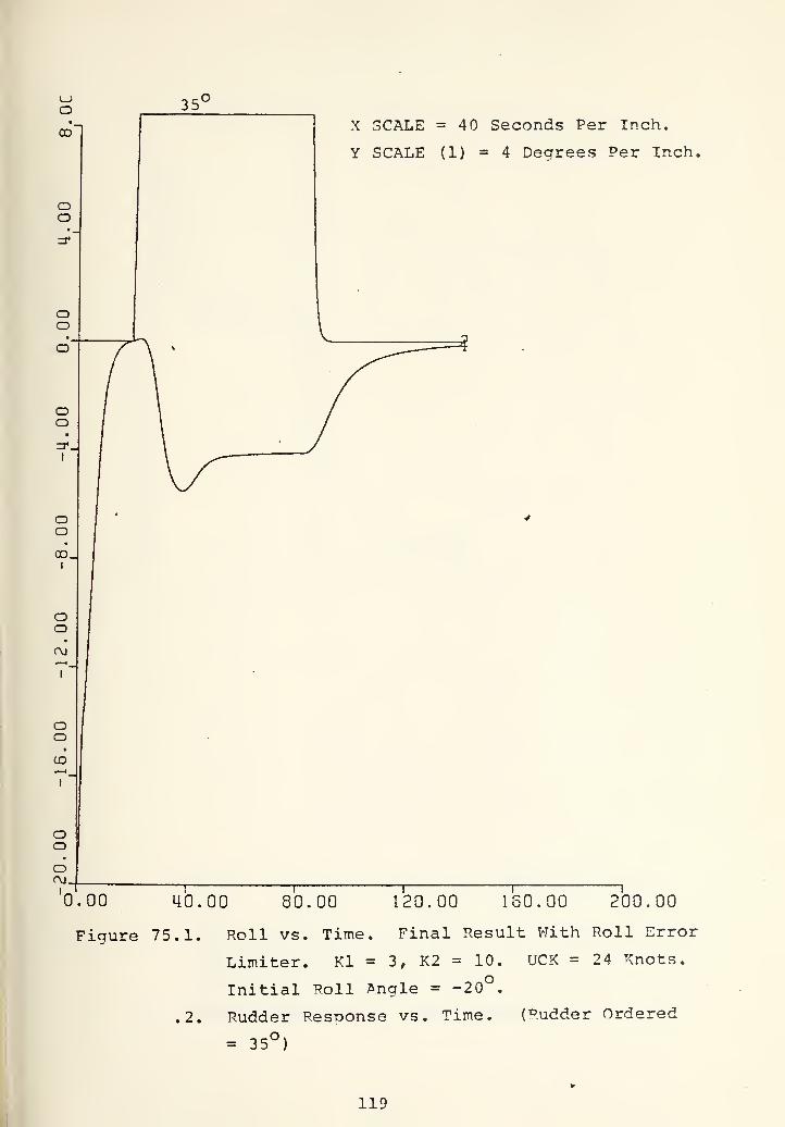
'o.oo
X SCALE = 40 Seconds Per Inch.
Y SCALE (1) = 4 Degrees Per Inch.
40.00 80.00 120.00 160.00 200.00
Figure 75.1. Roll vs. Time. Final Result With Roll Error
Limiter. Kl = 3, K2 = 10.
Initial Roll Angle = -20 .
UCK =24 Knots.
.2. Rudder Response vs. Time. (Rudder Ordered
= 35°)
119

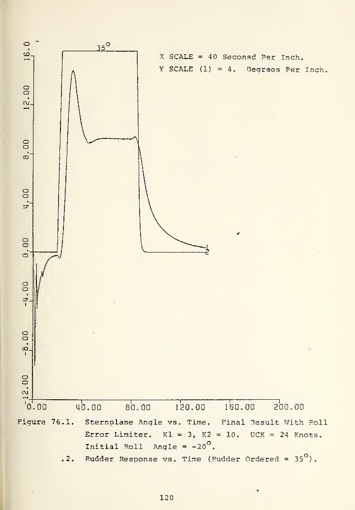
X SCALE = 40 Seconsd Per Inch.
Y SCALE (1) = 4. Degrees Per Inch,
0.00 40.00 80.00 120.00 160.00 200.00
Figure 76.1. Sternplane Angle vs. Time. Final Result With Roll
Error Limiter. Kl = 3, K2 = 10. UCK = 24 Knots.
Initial Roll Angle = -20°.
,2. Rudder Response vs. Time (Rudder Ordered = 35 )
.
120

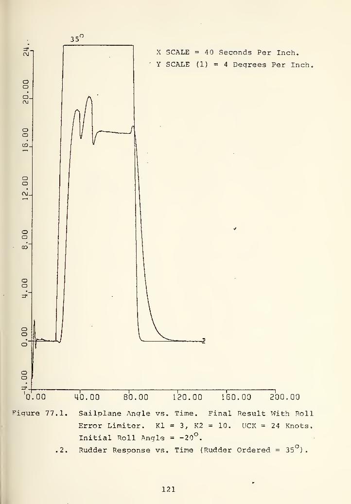
X SCALE =40 Seconds Per Inch.
Y SCALE (1) =4 Degrees Per Inch.
160.00 200.00
Sailplane Angle vs. Time. Final Result With Poll
Error Limiter. Kl = 3, K2 = 10. UCK = 24 Knots.
Initial Roll Angle = -20°.
.2. Rudder Resoonse vs. Tine (Rudder Ordered = 35 )
.
121


35^
X SCALE = 40 Seconds Per Inch.
Y SCALE (1) = 2 Feet Per Inch.
0.00
Figure 7 8.1.
40.00 80.00 120.00 ISO. 00 200.00
Depth vs. Time. Final Result With Roll Error Limiter,
Kl = 3, K2 = 10. UCK = 18 Knots. Initial ^oll
Angle = -20^.
.2. Rudder Response vs. Time (Rudder Ordered = 35 )
122

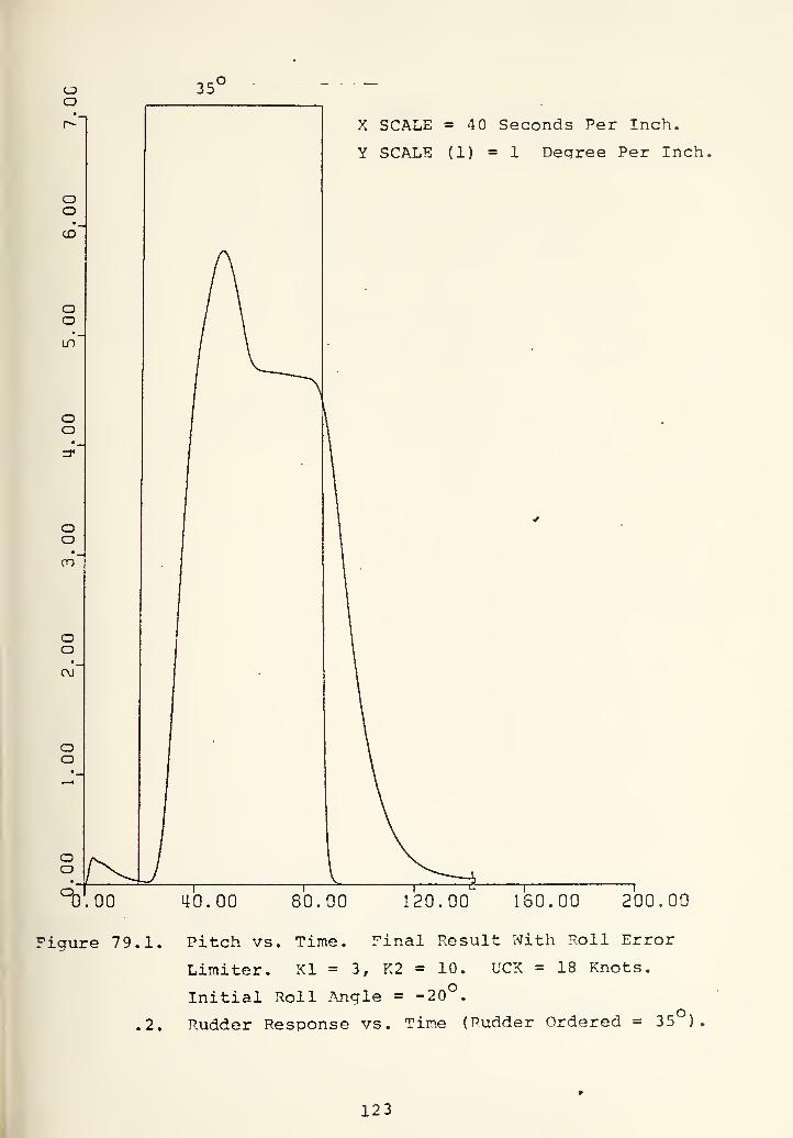
X SCALE = 40 Seconds Per Inch.
Y SCALE (1) = 1 Degree Per Inch,
0.00 40.00 80.00 120.00 160.00 200.00
Figure 79.1. Pitch vs. Time. Final Result With Roll Error
Limiter. Kl = 3, K2 = 10. UCK = 18 Knots.
Initial Roll Angle = -20 .
.2. Rudder Response vs. Tine (Rudder Ordered = 35 )
123

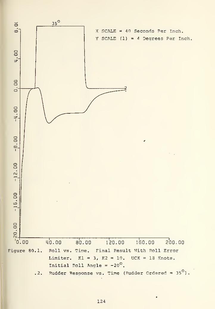
oooo.
I
oorvi
ooCD
I
oooCM.
X SCALE = 40 Seconcis Per Inch,
Y SCALE (1) =4 Degrees Per Inch,
0.00 40.00 80.00 120.00 160.00 200.00
Figure 80.1. Poll vs. Time. Final Result With Roll Error
Limiter. Kl = 3, K2 = 10. UCK = 18 Knots.
Initial Roll Angle = -20°.
.2. Rucicier Response vs. Time (Rudder Ordered = 35 )
124


35'
X SCALE =40 Seconds Per Inch.
Y SCALE (1) = 4 Degrees Per Inch,
0.00 40.00 80.00 120.00 160.00 200.00
Figure 81.1. Sternplane Angle vs. Time. Final Result With
Roll Error Limiter. Kl = 3, K2 = 10. UCK =
18 Knots. Initial Roll Angle = -20*^.
.2. Rudder Response vs. Time (Rudder Ordered = 35°)
125


CD_
OOO
I
'
oo
X SCALE = 40 Seconds Per Inch.
Y SCALE (1) = 4 Degrees Per Inch,
0.00
Figure 82.1,
40.00 80.00 120.00 160.00 200.00
Sailplane Angle vs. Time. Final Result With Roll
Error Limiter. Kl = 3, K2 = 10. UCK = 18 Knots.
Initial Roll Angle = -20°.
.2. Rudder Response vs. Time (Rudder Ordered = 35 )
.
126


35^
X SCALE =40 Seconds Per Inch,
Y SCALE (1) = 2 Feet Per Inch,
0.00 40.00 80.00 120.00 160.00 200.00
Figure 83.1. Depth vs. Time. Final Result With Roll Error
Limiter. Kl = 3, K2 = 10. UCK = 12 Knots.
Initial Roll Angle = -20°.
.2. Rudder Response vs. Time (Rudder Ordered = 35°)
127


X SCALE = 40 Seconds Per Inch.
Y SCALE (1) =1 Degree Per Inch,
Figure 84.1
40.00 80.00 120.00 160.00 200.00
Pitch vs. Time. ^inal Result With Roll Error Limiter.
Kl = 3, K2 = 10, UCK = 12 Knots. Initial Roll Angle
= -20°.
,2. Rudder Pesoonse vs. Time (Rudder Ordered = 35 )
.
128

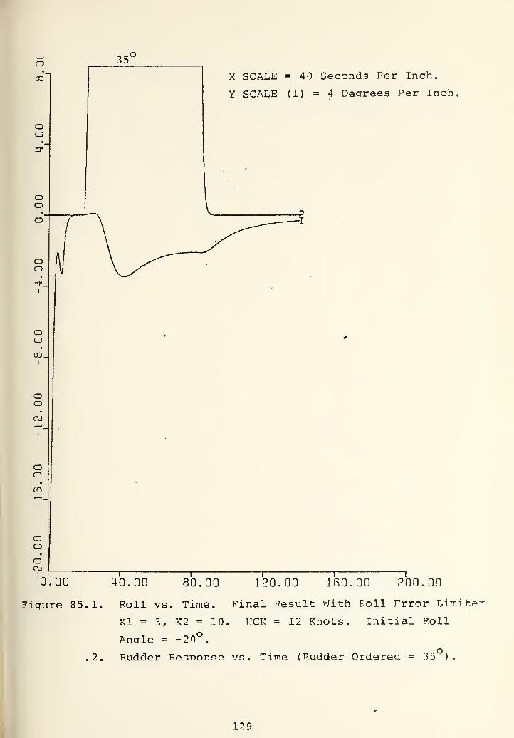
X SCALE = 40 Seconds Per Inch.
Y SCALE (1) = 4 Decfrees Per Inch,
0.00 40.00 80.00 120.00 160.00 200.00
Figure 85.1. Roll vs. Time. Final Result With Poll Error Limiter
Kl = 3, K2 = 10. UCK = 12 Knots. Initial Poll
Ancrle = -20 .
.2. Rudder Response vs. Time (Rudder Ordered = 35 )
.
129


35^
oo
oI
'
ooin
oooC\J_
I
ooinCM.
X SCALE = 40 Seconds Per Inch.
Y SCALE (1) = 5 Degrees Per Inch,
0.00 40.00 80.00 120.00 160.00 7oo.oo
Figure 86.1. Sternplane Angle vs. Time. Final Result V7ith
Roll Error Limiter. Kl = 3, K2 = 10. UCK =
12 Knots. Initial Roll Angle = -20°.
.2. Rudder Response vs. Time (Rudder Ordered = 35°).
130

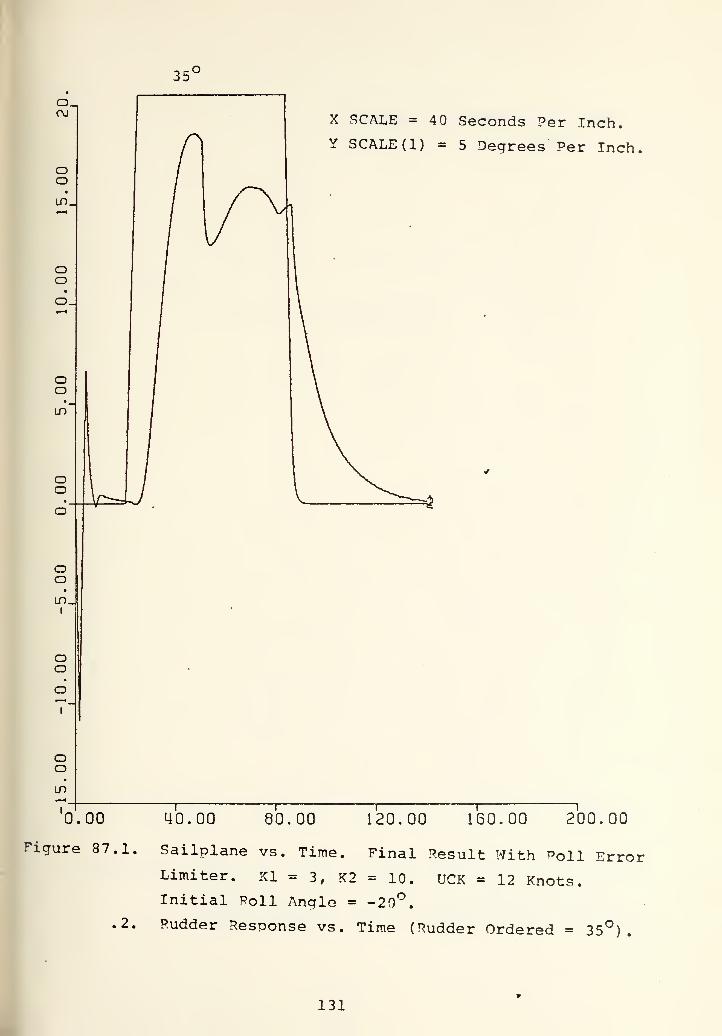
35'
X ^CALE = 40 Seconds Per Inch.
Y SCALE (1) = 5 Degrees Per Inch,
0.00
Figure 87.1.
.2.
40.00 80.00 120.00 160.00 200.00
Sailplane vs. Time. Final Result With Poll ErrorLimiter. Kl = 3, K2 = 10. UCK = 12 Knots.Initial Poll Angle = -20*^.
Rudder Response vs. Time (Rudder Ordered = 35°).
131


X SCALE =40 Seconds Per Inch,
Y SCALE = 2 Feet Per Inch.
0.00 40.00 80.00 120.00 160.00 200.00
Figure 88. Depth vs. Time. Final Result With Roll Error
Limiter. Kl = 3, K2 = 10. UCK = 24 Knots.
Rudder Ordered = 35*^. Initial Roll Anale = 0°,
132

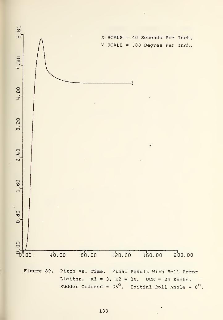
CD
in
ooo
oo
oC\J
oo'
o
(\l'
oCD
ooo
oo
X SCALE =. 40 Seconds Per Inch,
Y SCALE = .80 Decree Per Inch,
^.'oo 40.00 80.00 120.00 ISO. 00 200.00
Figure 89. Pitch vs. Time. Final Result With Poll Error
Limiter. Kl = 3, K2 = 10. UCK = 24 Knots.
Rucider Ordered = 35°. Initial Roll Angle = 0*^
133


o(M
o"
oCD
O
o
OJ.I
oo
•
en.I
ooo
CO.I
oCD
zr.I
ozr
in.
X SCALE = 40 Seconds Per Inch,
Y SCALE = .80 Degree Per Inch,
0.00 40.00 80.00 120.00 160.00 "200.00
Figure 90. Roll vs. Time. Final Result With Roll Error
Limiter. Kl = 3, K2 = 10. UCK = 24 Knots.oRudder Ordered = 35 Initial Roll .Ancrle =
134

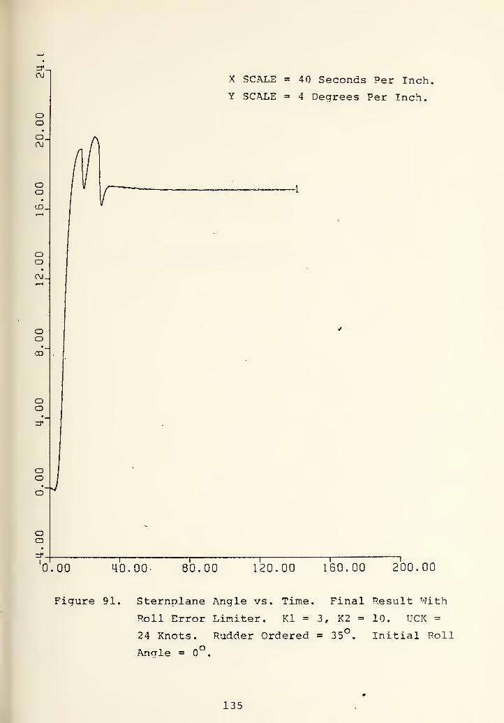
X SCALE = 40 Seconds Per Inch,
Y SCALE = 4 Degrees Per Inch.
(jd_
(\j.
CO
0.00 40.00 80.00 120.00 150.00 200.00
Figure 91. Sternplane Angle vs. Time, Final Result With
Roll Error Limiter. Kl = 3, K2 = 10. UCK =
24 Knots. Rudder Ordered = 35°. Initial Roll
Angle = .
135


CD_
X SCALE = 40 Seconds Per Inch
Y SCALE =4 Degrees Per Inch.
CM-
CO
CO.
0.00 40.00 80.00 120.00 160.00 "2^00.00
Figure 92. Sailplane Anqle vs. Time. Final Pesult With
Roll Error Limiter. Kl = 3, K2 = 10. UCK =
24 Knots. Rudder Ordered = 35
Roll Angle = 0°.
Initial
136


ru_
X SCALE =40 Seconds Per Inch,
Y SCALE = 2 Feet Per Inch.
0.00 40.00 80.00 120.00 ISO. 00 200.00
Figure 93. Depth vs. Time. Final Result With Roll Error
Limiter. Kl = 3, K2 = 10. UCK = 18 Knots.
Rudder Ordered = 35°. Initial Roll Ancrle = 0°,
137


X SCALE =40 Seconds Per Inch,
Y SCALE = 1 Degree Per Inch.
oo
CDO
OO
oo
• ^
en'
oo
oo
oo
^^00 40.00 80.00 120.00 160.00 200.00
Figire 94. Pitch vs. Time. Final Result With Roll
Error Limiter. Kl = 3, K2 = 10. UCK =
18 Knots. Rudder Ordered = 35*^. Initial
Roll Angle = 0°.
138


(\)_
cn_
0.00
X SCALE = 40 Seconds Per Inch.
Y SCALE = .80 Decrrees Per Inch
40.00 80.00 120.00 160.00 200.00
Figure 95. Roll vs. Time. Final Result With Roll Error
Limiter. Kl = 3, K2 = 10. UCK = 18 Knots.
Rudder Ordered = 35 Initial Roll Angle =
139


X SCALE =40 Seconds Per Inch,
Y SCALE = 4 Degrees Per Inch.
0.00 40.00 80.00 120.00 150.00 200.00
FicTure 96. Sternplane Angle vs. Time, Final Result With
Roll Error Limiter. Kl = 3, K2 = 10. UCK =
18 Knots. Rudder Ordered = 35°. Initial Roll
Angle = 0°.
140


C\J
oo
X SCALE =40 Seconds Per Inch
Y SCALE = 4 Degrees Per Inch.
00
CO.
0.00 40.00 80.00 120.00 160.00 Too. 00
Fiqure 97. Sailplane Anale vs. Time. Final Result With
Roll Error Limiter. Kl = 3, K2 = in. UCK =
18 Knots. Rudder Ordered = 35*
Roll Angle = 0°.
Initial
141


CM.
OO
X SCALE =40 Seconds Per Inch,
Y SCALE = 2 Feet Per Inch.
0.00 40.00 80.00 120.00 160.00 2^00.00
Figure 98. Depth vs. Time. Final Pesult WithRoll Error Limiter. Kl = 3, K2 = 10. UCK =
12 Knots. Rudder Ordered = 35°. Initial RollAncTle = 0°.
142


a
ooto'
ooLO'
oo
ooon"
ooru'
oo
oo
X SCALE = 40 Seconds Per Inch.
Y SCALE = 1 Dearee Per Inch.
0700 40.00 80.00 120.00 160.00 200.00
Figure 99 . Pitch vs. Time. Final Result With Poll Error
Limiter. Kl = 3, K2 = 10. UCK = 12 Knots.
Rudder Ordered = 35°. Initial Roll Angle = .
143


CDX SCALE = 40 Seconds Per Inch.
Y SCALE = .80 Degrees Per Inch,
0.00 40.00 80.00 120.00 160.00 "200.00
Figure 100. Roll vs. Time. Final Result With Roll Error
Limiter. Kl = 3, K2 = 10. UCK = 12 Knots.
Rudder Ordered = 35°. Initial Roll Angle =,
144


CD_
CM-
CO
X SCALE =40 Seconds Per Inch
Y SCALE = 4 Degrees Per Inch.
0.00 40.00 80.00 120.00 160.00 200.00
Fiaure 101. Sternplane Angle vs. Time. Final Result With
Roll Error Limiter. Kl = 3, K2 = 10. UCK =
12 Knots. Rudder Ordered = 35°. Initial Roll
Angle = .
145


oOJ.
oo
X SCALE =40 Seconds Per Inch,
Y SCALE = 2 Degrees Per Inch.
0.00 40.00 80.00 120.00 160.00 200.00
Figure 102. Sailplane Angle vs. Time. Final Result With
Roll Error Liraiter. Kl = 3, K2 = 10. UCK =
12 Knots. Rudder Ordered = 35°. Initial i^oll
Angle = .
146


o
CDo
oo
I
oooo_
I
ooCM
1
'
OoCD
I
'
ooo(M_|
I
oo
X SCALE =40 Seconds Per Inch,
Y SCALE = 4 Degrees Per Inch.
0.00 40.00 80.00 120.00 160.00 7oo.oo
Figure 103. Roll vs. Time. Final Result With Roll Error
Limiter. Kl = 3, K2 = 10. UCK = 24 Knots.
Rudder Ordered = 35°. Initial Roll Anale =
-20°.
147


o
oo
X SCALE =40 Seconds Per Inch
Y SCALE = 4 Degrees Per Inch.
oo A 1
I V/
oo
• •
oo_1
oo
y
Ol
1
> -
oo
•
(D
1
~•
oo
•
o0J_
1
oo
•
zrC\J_l-J _- 1 1 1
1 1
0.00 40.00 80.00 120.00 160.00 200.00
Figure 104. Roll vs. Time. Final Result With Roll Error
Limiter. Kl = 3, K2 = 10. UCK = 18 Knots.
Rudder Ordered = 35°. Initial Roll Angle
= -20°.
148


oo
oo
oo::r.
I
oo
I
oo
•
C\J
I
oo
I
'
oooCM.
Oo
CM.
X SCALE = 40 Seconds Per Inch,
Y SCALE = 4 Degrees Per Inch.
0.00 40.00 80.00 120.00 160.00 200.00
Figure 105. Roll vs. Time. Final Result With Poll ErrorLimiter. Kl = 3, K2 = 10. UCK = 12 Knots.
Rudder Ordered = 35°. Initial Roll Angle =
-20°.
149


same test without roll limiter as was discussed above
gave an unstable system but after inserting the limiter
the result was stable over the speed range of interest.
In contrast to the results shown in Figures 67 through 71,
there is no oscillation in the roll and sailplanes re-
sponses in the time interval of - 20 seconds and it
was observed that the limiter gave very good damoing to
the system. This last statement can be justified by
inspection of Figure 75 such that at time equal 20
(when the rudder is commanded to full deflection) the
roll response is almost zero without any orevious oscil-
lation. As the stabilization in three dimensions v/as being
reached the stern and sailplanes never went into saturation,
2. Figures 88 through 192 record the depth, pitch, roll,
sternplane and sailplanes responses at 24, 18, and 12
knots to 35 rudder command (the rudder is commanded to
full deflection of the beginning of the simulation) with
zero initial roll angle. It is observed that without
using excessive stern and sailolane deflection great sta-
bility in the three dimension has been reached. As was
shown before. Figures 44 through 55 record the responses
of the system without roll controller to the identical
test. Comparison of these tests is made in the Table II.
It is seen that at high speed great improvement in the
sense of maximum and steady state value has been obtained.
150


TABLE II
IMPROVEMENT DUE TO ROLL CONTROLLER
UCK WITHOUT ROLL CONTROLLER WITH ROLL CONTROLLER
MAX STEADY STATE MJ\X STEADY STATE
Depth Changed 8.5 ft. 8 ft.
24 Pitch UNSTABLE 5°.
5
4°.
4
Roll 5°.
3
4°
Depth Changed 10.1 8.7 8.5 8 ft.
18 Pitch 9.5 5° 5°.
6
4°.
7
Roll 23° 6° 4°.
6
3°.
2
Depth Changed 9.7 ft. 9.5 ft. 9.2 9
12 Pitch 7° 5°.
7
6.7 5.2
Roll 10°.
3
2.5 3°. 5 2°
151


3, Figures 103 through 105 record the roll resoonses of the
system at 24, 18, and 12 knots to 35 rudder deflection
(the turn was commanded at the beginning of the simu-
lation) v'ith 20 inboard roll angle. The results are
stable. Comparison of Figure 10 3 with Figure 66 shows
the improvement obtained by inserting a roll limiter such
that it damped out the oscillation.
It was shoT-^m that utilizing the fairwater planes as
the control surface of the roll controller not only stabilized
the roll response but also gave big improvement in the depth
and pitch controller. In the following section stability
tests of the system to disturbance moments is discussed.
C. ROLL CONTROLLER STABILITY TESTS
Since the roll controller design was carried out usina
nonlinear equations in six degrees of freedom, the stability
analysis of the system was not practical. To investigate the
stability comouter simulation was used by applying disturbance
moments. The magnitude of the moments was
DISTURBAxNCE = KS* (UCK) ^*L"^ where
KS = 4,0*0.0003*576/(UCK)^
The disturbance moment was calculated by assigning non-
zero value of KS which was normally zero and reoresents the
hydrodynamic coefficient which gives the rolling moment when
body angle and control surface angles are zero. The magnitude
of the disturbance was four times biqger than that used in the
stability analysis of Stamps controller. At 24 knots the
152


7magnitude of the disturbance was 1.1028x10 ft-lb. such that
the Stamps controller was unable to stabilize the system to
7the disturbances of the magnitude m the order of 10 . Figures
106 through 120 record the depth, oitch, roll, sternplane, and
sailplanes responses to the inboard roll moment dis-
turbance mentioned above. The distrubance was applied at time
equal 20 as a step moment. Curve number 2 represents the dis-
turbances. Inspection of the results shows that the system is
stable in three dimensions to the disturbances moment. The
worst affect of the disturbances was seen at low sDeed test
v/hich was normal. But even in this case, after a transient re-
sponse the system was stable.
153


X SCALE =40 Seconds Per Inch,
Y SCALE (1) =2 Feet Per Inch.
0.00 4U. UU au. uu Tzormr ISO. 00 200.00
Figure 106.1. Deoth vs. Time. Roll Stability Steo Test.
UCK = 24 Knots. Rudder Ordered = 35^.
.2. Disturbance Moment vs. Time (1. 1028*lo'^ft-lb.
154


oCD
OOO
OO
OCM
cn'
o
c\j"
oCD
OOO
oo
°oToo
X SCALE = 40 Seconcis Per Inch.
Y SCALE (1) = 0.80 Degrees Per Inch,
4U.UU bU.UG TTTDTOD^ 160.00 200.00
Figure 107.1. Pitch vs. Time.
UCK =24 Knots.
Roll Stability Steo Test.
Rucider Orciereci = 35*^.
.2. Disturbance vs. Time. (1. 1028*10 ft-lb. )
.
155


oo
X SCALE = 40 Seconds Per Inch.
Y SCALE (1) = 2 Degrees Per Inch.
0.00 40. UU dU.UU TZUTOTP ISO. 00 "?00.00
Figure 108.1. Roll vs. Time. Roll Stability Step Test. UCK
= 24 Knots. Rudder Ordered = 35°.•7
.2. Disturbance Moment vs. Time (1. 1028x10 ft-lb. )
.
156


UD_
C\l_
CO
o
0.00
X SCALE = 40 Seconds Per Inch.
Y SCALE (1) = 4 Degrees Per Inch,
40. UU yu.uu 1^0. UU"- 160.00 200.00
Figure 109.1. Sternnlane Anale vs. Time. Roll Stability Steo
Test. UCK = 24 Knots. Rudder Ordered = 35°.
.2, Disturbance Moment vs. Time (1.1028x10 ft-lb.).
157


oo.
OO
0.00
X SCALE = 40 Seconds Per Inch
Y SCALE = 4 Degrees Per Inch.
4U.UU yu.uu T2UTWI 160.00 200.00
Figure 110.1. Sailplane Angle vs. Time. Poll Stability Step
Test. UCK = 24 Knots. Rudder Ordered = 35°.
.2. Disturbance Moments vs. Time. (1. 1028x10 ft-lb.
)
158


X -^CALE = 40 Seconds P^r Inch.
Y SCALE (1) = 2 Feet Per Inch.
0.00 40.00 80.00 rZOTUTP 160.00 200.00
Figure 111.1. Depth vs. Time. Roll Stability Step Test.
UCK = 18 Knots. Rudder Ordered = 35°.7
.2. Disturbance Moment vs. Time. (1.1028x10 ft-lb.
)
159


oo
•__
oocd'
oo
• _
in'
oo
oo
• _
en'
oo
m ^
C\j"
oo
oo
X SCALE = 40 Seconds Per Inch.
Y SCALE (1) = 1 Degree Per Inch,
°oToo 4U.UU 8U.UU T?DTair 160.00 7oo.oo
Figure 112.1. Pitch v?;. Time. Poll Stability Steo Test.
UCK = 18 Knots. Pudder Ordered = 35°.7
.2. Disturbance Moment vs. Time. (1.1028x10 ft-lb.)
160


OJ
ZT-
CD.
0.00
X SCALE = 40 Seconds ^er Inch.
Y SCALE (1) = 2 Dearees Per Inch,
40. UU yu. uu IdU. UL^ 160.00 7oo.oo
Figure 113.1. Roll vs. Time. Roll Stability Sten Test.
UCK = 18 Knots. Rudder Ordered = 35^.
.2. Disturbance Moment vs. Time. (1. 1028x10*^^ t-lb. ).
161


0.00
X SCALE = 40 Seconds Per Inch.
Y SCALE (1) = 4 Degrees Per Inch,
LiU.UU UG.UU Tzunrtf 160.00 200.00
T^'igure 114.1. Sternolane Anale vs. Time. Roll Stability Sten^oTest. UCK = 18 Knots. Rudder Ordered = 35
.2. Disturbance Moment vs. Tine. (1.1028x10 ft-lb.).
162


o
0.00
X .SCALE =40 Seconds Per Inch.
Y SCALE (1) = 4 Dearees Per Inch
"TOTircr dU.UU ISO. 00 200.00
Fiaure 115.1. Sailplane Anale vs. Time. Roll Stability Steo
Test. UCK = 24 Knots. Pudder Ordered = 35°.
.2. Disturbance Moment vs. Time. (1.1028x10 ft- lb.)
163


X. SCALE =40 Seconds Per Inch.;
Y SCALE (1) = 2 Feet Per Inch.'
°0^00 160.00 200.004U. UU dU.UU T2UTTKF
Figure 116.1. Deoth vs. Time. Roll Stability Step Test.
UCK = 12 Knots. Pudder Ordered = 35°.
.2. Disturbance Moment vs. Time. (1. 1028xlo'^ft-lb. )
164


0.00
X SCALE = 40 Seconds Per Inch.
Y SCALE (1) = 2 Degrees Per Inch.
4U.UU yu.uu IZU.Uif 160.00 200.00
Figure 117.1. Pitch vs. Time. Roll Stability Steo Test.
UCK = 12 Knots. Rudder Ordered = 3 5°.
.2. Disturbance Moment vs. Tim-e. (1.1028x10 ft-lb. )
165


C\J
oo
o_
LD
O
I 0.00
X SCALE = 40 Seconds Per Inch.
Y SCALE (1) = 5 Degrees Per Inch,
4U. UU yu.uu TZUnXF 160.00 200.00
I
I
Figure 118.1. Roll vs. Time. Roll Stability Sten Test.
UCK = 12 Knots. Rudder Ordered = 35°.
.2. Disturbance '^oment vs. Time. (1.1028x10 ft-lb.)
166


0.00
X SCALE = 40 Seconds Per Inch.
y SCALE (1) = 8 Decrees Per Inch,
40.00 bu. uu T2xrrxK? 160.00 "?00.00
Figure 119.1. Sternplane Angle vs. Time. Poll Stabilitv
Step Test. UCK = 6 Knots. Rudder Ordered = 35*^.
.2. Disturbance Moment vs. Time. (1. 1028xl0^t-lb. ) .
167


X SCALE =40 Seconds Per Inch.
Y SCALE (1) = 8 Degrees Per Inch,
0.00 4U. UU «u. uu ramrtf 160.00 200.00
Figure 120.1. Sailplane Angle vs. Time. Roll Stability Steo
Test. UCK = 12 Knots. Rudder Ordered = 35°.
.2. Disturbance Moment vs. Time. (1. 1028x10 ft- lb.
)
168


VI. DISCUSSION, CONCLUSIONS AND RECOMMENDATIONS
FOR FURTHER WORK
A. DISCUSSION AND CONCLUSION
The characteristic of a submarine which is totally
submerged and in a high speed turn was discussed in Chapter II
and the simulation results were given in Chapter III. The
unhydrodynamic body structure when it is submerged, which is
mainly due to the appendaaes (sail) , was considered the main
source of the problem. The necessity of the sail that provides
rooms for periscope and other vital controls that are located
in the tower does not oermit a small sail structure. On this
account, a control scheme must be used to compensate the prob-
lems that stem from the sail. The complexity of controlling a
submarine in a high speed turn, comes from the coupling between
states and three-dimension dynamics. In Chapter IV an automatic
depth and pitch controller was presented briefly with the modi-
fication of the original design represented in Reference 7.
The automatic control scheme gave the advantage of taking depth
and pitch error and their rate into account. But, since only
the sternplane was used as a control surface, the results made
the roll controller design necessary for controlling the ship
within the wide range of speeds and under various disturbance
conditions. The imposition of the fairwater Diane to control
roll, which was the main goal of this thesis, gave a great
amount of expected improvement to the system. The roll
169


controller scheme was carried out by using equations of motion
(nonlinear) in which the vertical plane dynamics were stabil-
ized by the imposition of the depth-pitch controller, and roll
state and roll rate gave enough information to provide closed-
loop control for the ship. The control scheme was a direct
roll controller compared to the controller designed by Stamps
in Reference 2. Stamps 's controller was an indirect roll con-
troller and in his design the rudder was used as a function of
the integral of roll error which was the difference between the
allowed maximum roll and the actual instantaneous roll angles.
The initial rudder ordered was to be such that the peak roll
expected for a given approach speed would be less than the
maximum allowed roll. The integral of roll error was then to
be computed and scaled to represent an additive tern applied
to the initial rudder order (8rO) . The instantaneous rudder
order (DRCOM) was then to be computed
DRCOM = 6ro + K_ ((^ - (TJ ^) dt.I r max ract
The technique reported in this thesis has the benefits of
simplicity and costs much less than alterations of the design
criteria of Ilavy submarines. But since it prohibited use of
a hard rudder deflection (35 ) in the early phase of turn, the
time required to pass any specified yaw angle v/as quite long.
For this reason, the roll control, in a direct sense, by making
use of fairwater planes as control fins, was investigated in
the proposed design. As a result, not only were the dangerous
snap rolls decreased to magnitudes of 5 , but also with the hard
170


rudder deflection a big yaw rate was achieved. In Table III,
the oerformance of the submarine with each of these two roll
controllers is compared. In the Stamps' design, maximum roll
angle is predetermined and the controller is designed not to
exceed this value. The higher allowed maximum roll angle gives
higher yaw rates. In the proposed desicrn, maximum roll anale
is the result of the system's dynamics.
TABLE III
COMPARISON OF THE PROPOSED AND STA.MPS ' DESIGN
TYPE OFCONTROLLER
MAXROLL
APPROACHSPEED
TIME REQUIRED IN SECONDS TOPASS SPECIFIED YAW ANGLE
STAiMPS' DESIGN7^5
241812
45° 90° 180°
523927
916747
7100710083
DIFFERENTIALFAIRWATERPLAICE
5°. 61
4^.69
3^4
24
18
12
11.5
14
19
20
25
36
41
54
80
I
It is seen that the use of differential fairwater planes
provides a faster response with reduced maximum roll angle at
all speeds.
In the proposed design, only one fairwater plane actu-
ator was used and it was assumed that it gives deflection in a
differential mode. Switching criteria from the conventional
usage of the fairwater plane (both starboard and port sides
move simultaneously in the same direction) to the differential
mode was not discussed.
171


This research has shown that imposition of the fairwater
Diane as a part of the roll controller improved the control of
a turning high speed submarine in three dimensions. Dangerous
snap roll was decreased to around 5 and with only sternplane
and the stabilized roll response high improvement in the deoth
and pitch characteristic v/as achieved.
B. RECOMMENDATIONS FOR FURTHER WORK
The following research would be worthwhile in future
studies
:
1. Automatic death and pitch controller by usina only
sternplane in the sense of an optimal feedback controller
for linear tracking should be designed and the combina-
tion of this design with the oresent roll controller
should be investigated. This study would give good in-
sight into the problem which comes from the depth changing
when the submarine is in a high speed turn.
2. Switchina criteria from the roll controller of Reference
2 to the proposed roll controller should be established
and these two designs should combine together. This would
give better depth and pitch control to the ship when it
has low speed where a great amount of roll control is
not needed.
3. With the coordination of NSRDC a more accurate hydrodynamic
coefficient associated with the differentially deflected
sailplane should be obtained.
172


4, Addition of an integral of error to the roll control
should be studied to see if the steady state roll angle
can be reduced.
173


.APPENDIX A •
EQUATIONS OF MOTION
The following set of equations ;ire referred to a bodyfixed systcn of axes whlcU arc colnctdcnC with the prin-cipal axes of Inertia of the body. The origin of thisaxls-sys tcim Is located at the assumed center of mass ofChe bodv
Equation of Motion Along the Body Axis System x-Axls
m{u - vr + wq)= f i* [x^^
• q' + X^^ ' '' ^^ ^rp
' '?]
I
. f X- [X . • u . X ^^ . vr . X ^^ . wq]
I
»
+ ^z^ Fx • u* + X • v'+ X • -22 L uu vv WW w
i L oror r osos a 6b6b b J
+ -f£* X ,
' (n' - I) V*Z vvn' *
'
+ -|i' X ,• (n" - I) w»
Z wwn' '
+ f /^i2X . - ,• (n* - 1) 6 '
c &s6sn' ' s
c 6r6rn' r
- SW. sin e
* <^x'p
174


Equation of Hodon Along Che Sody AxLs S/scem y-AxLs
m(v . wp + ur) = |i* [Y*'f+Y.'p]
^-fi* [y. -WY^ •-P+Y,,,,.VjI(v^.w')h lr|]
+ |X- [y^ '"'^^|r|6r 'MrUr^Y^ 'up]
+|Z' [y^ -u'+Y^ •uv+ Y^j , -vKv^ + w^)^!]
2 6r r
*l^'"'^6ra' •("•-!) 6^
+ |i' Y^^, • (n- - I)uv
+ l^'^v|v|n' •<"' - l)v|{v' + w')^|
fi» Y • wvl^ wv
+-fxMFy)^^ v' f w' (-W) Sin.wt I Multiplied byU u
. _ . for large .ingles of+ EWj 8m(|)co8 9 attack near -90'
175


Cquaclon of Motton Along the Body Axis System z-Axl«
m(w - uq + vp) - J t Z . ' q
Note 1
i- -q
*^X» [^ w • ^ ^ ^ vr • -' ^ ^ vp • -P ^ ^2 vp • -P']
*l^' ^qn- •^"•- »>«*l
+ J?/M''z, ,' ulwi + Z ' |w (v^ + w^)-l + Z 'v'#12 ' 1^1 ' ' WW ' * '
' vv J
-?iMf )v' ^^ w' V Sin ojt
+ EW. cos 9 COS (j)jif Multiplied by '
u
for large angles ofattack near -90*
Note 1
when not multiplied byu add to Z *
D vp
176


Equadon of Hocion AbouC che Bod/ Axis S/scen x-Axis
I^MI.-yqr --|Z* [k. 'p^K^^ Mr.K. ' r . K ^'jp, .
pj^Q
?x* [k ' up + K ^ • ur + K ^ ' ^ + ^ wp ' ^]
+ -|z' [k ' u'+K^ • uv + K^-j^j ' vj(v» +wM^l]
i vw
|.'u'K,, '«,
+ Bz Q ain <{) cos 9
177


Equadon of Kocion AbouC Che Body Axis Syscem y-Axls
Note 1
+ -?i* Fm . • w + M • vr/^ + M • vp**]i L w vr vp J
+ l^*^qn' •^"•- ^'"'l
+ |i' [m, 'u'+M^ 'uw + M^,^, w|(v»+w'l^r]
+ -?i* Fmi ,'uIwI + M • Iw(v2+w^)hfM 'y^i^Z L |w| ' ' WW '
' < vv J
P- u' [m^^ •4.^^^6b '^]
+ I i^ M , ' (n» - 1) uwZ wn" '
+ 1^"*^wlw|a' •'"' - nw|(v2 + ,,2)^|
+ -f i* u* M . , • (n* - 1) &i 6sn' I
+ Bzj^
sin 9
- EWJx^. cos 9 cos ^
# Multiply by g- forlarge ancles orattacknear -90^
Note 1
when not multipliedby ii add to M •
178


I!quaClon of Modon AbouC Che Body Axis S/acen t-Axls
^rMIy-gpq ^ji' [^i "^^^p^'P<i^^^ 'P]
+ -^ t
+ -|x*[n »up+N^'v+N^ • wp]
+-f
X* N^^, • (n- - I)ur
2 6r r
I'' "'^5rn' •(--')»,
*!'' "vn- '<"'-" uv
* 1'^''^vjvln'
•^"'- n vI(v'+wM^I
+ f X' N » wvli wv
+ EW x^^ cos 9 sin(|> I Multiply by - for largeangles of attack near -90*
179


AUXILIARY EQUATIONS
(J)s p ^ i sin9
9 « (q - iicos9 sin4> ) / cos<t>
i>s ( r + 9 8in4> ) / cos 9cos4)
xo = uco89cosi^-f-v(sin<psin9cos^-co6<P3in^)
w(ain4)3in!^fcos<J)sin9cos^)
yo = uco89 8ini/) + v(cos<t)cos)^ + sin4'sin9 3iin(>)
+ w (cos({)sin9 sirni) - sin 4) cos <|))
Zq s - u sin 9 + V cos 9 sin<{) + w cos 9 cos ({)
s |x^ u*[ V + ba' n' + ba'n'^] when k, < n' < k^
= |z'u*[ c^' + c,' n* + Ca'n'*] when kj < n' < k^
s 52'u'[ di' + dj'n' + d^'n'O when n' < k^
« » I
^1» ^2* ^3 Sets of non-dl-.cnslot.Al coefficients used In the pro-
( , ,pulsion equation above, ".'h'' set vhlcl: will be In effect
Ci# C2» c-\ at any tl.Te durlnr; a slnjlaVci raneuver vlll depend on t^e
, , ,value of n and the nu-nbers k,,kp,k..
di, d2, dj 1*i 3
180


NOMENCLATUW!
All symbols used In Che equations of notion and In Chc
auxiliary e'*.uaClon3 and relationships which appear In this
report are defined below. Any dimensions Involved will b«
consistent with the f oot -ponnd-sccond system of units. All
angles are In degrees. The Fortran variables corresponding
Co these symbols are shown In Appendix 5
SYMBOL DEFINITION
• A dot over any symbol signi-
fies differentiation with res-
pect to time.
B Buoyancy force which is posi-
tive upwards.
a Mass of the submarine Including
the water In the free fJiofJ^^S
spaces .
^ Overall length of the submarine
U Linear velocity of origin of
body axes relative to an earth-
fixed axis system.
u Component of U along the body
X-axis
.
V Component of U along the body
y-axis.
w Component oT U along the body
t-axls .
181


Command speed: A sceady value
of u for a given propeller rpa
whenc^.p and concrol surface
angles are zero. Sign changes
vlch propeller reversal.
Long
i
Cudlna 1 axis of the body
fixed coordinate axis system.
Transverse axis of the bo<iy
fixed coordinate axis systeo.
Vertical axis of the body fixed
coordinate axis system.
Distance along the x^ axis of aa
earth-fixed axis systeo.
Distance along the y axis of an
earth-fixed axis system.
Distance along the z- axis of an
earth-fixed axis system.
CoQponcnt of angular velocity
about the body fixed x-axls.
Component of angular velocity
about the body fixed y-axls.
Component of angular velocity
about the body fixed z-axls.
The z coordinate of the center
of buoyance (CB) of the subma-
rine.
182


Angle of aCCacSc.
p
Sb, Dfc
Sr, Dr-
Ss, Dj
An^le of drift.
Deflection of bowpUne ( or••llplane )
Deflection of rudder.
Deflection of aternplane.
e
$
C
6>
The ratto u^/u.c
Pttch angle.
Yaw angle.
Roll angle.
Mass density of sea valer.
tfelRht of water blown from a
particular ballast tank Idenc^If^Ied by the Integer assignedto the Index 1.
Angular velocity.
Time.
ei Location along the body x-axlsof the center of mass of th# 1 Ch
ballast tank when this tank lafilled with sea water.
133


«Vp Propulsion force (see auxi-
liary equations and relation-
shl pa) .
Moment of Inertia of « sub-
narlne about the x-axls.
Moment of Inertia of a sub-
marine about the y-axls.
Moment of inertia of a sub-
oarine about the z-axis.
k;. k^'. k.'. k^p'. k/.
^V '^v jvj • ^vw» J^Sp'
Kon-dlmens lona I constants each
of which Is assigned to a parti-
cular force tern In the equation
of motion about the body x-axls.
H. •. M •
, M •, AM •
, M , M.I
.',
q * rr ' rp rp ' q (q|<5a
Ml I . M. • . M '. M ', M ', M.', Non-dlraonslonal constants eachI w| q w * vr vp ' qn »
of which Is assigned to a partl-
M *. M I 1 ! Ml ,' , M ', M ', M. ', cular force term in the equationW w|wl |w| WW VV 8
of motion about the body y-axis.
4b wn • w w n ' osa
184


^'' %q'' %•• ^•• '|r|6r'' «Iv|r*
%'. ^Z' ^p•• ^a••• ^*'- ^••Non-d Inena lonal consCancs each
of which Is asnlgncd Co a parcl*
cular force Cern In Che equadon
''vlvl'* ^(Sr'* ^6rn''' ^'vn' * '^vlvln' 'of mocton abouC Che body x>«xts.
wv
qq rr rp u * vr wq •
X » X • X * X 'X ' Non-dlmens lonal conscancs eachuu * vv • WW • 5 ri5 r ' 5 a4 a *
X * X • X ' X • cular force term In Che equadon5 bo b vvn wwn 6 ai sn *
^«r«ra'*
of which Is assigned Co a parcl*
cular force cerm In Che equadon
of Dodon along the body x-axla.
' p pq piPi V wp
, Kon-dlmcns lonal conscancs eachY,,»v»v "viv I Non-dlmcns iona 1 conscancs eacnv|r| • ^r • r|5r * ^p • ^rn' *
of which Is assigned Co a pard
•y«v..»v»v • cular force Cera In che equado-
of nodon along Che body y-axtiV V
\n'*' ^v|v|n''' ^wv'» ^Vvs
^4** ^rr'' '-rp'* ^w' • ^vr* ^vp''
2«,^ » 2„„ , z. , z.. , z , ,
;jtfjn" ^5sn" ^^z'va
Kon-d Imens lonal consCancs each
of which Is assigned Co a pard-
cular force Ccrn In Che equado*
of modon along the body z-axls
185


-1
APPENDIX B
o
^ <j a: ni
It u. pi n» r*
(_. UL r-f I o in (T*
CM- 'j.i CI" c cr n3-c oL-. LL Q .^ I r«- • ^ C~- II CL U_ IL --• C O I i/> •
CO. >- r-ii^ II • i; it cc'(rr-_J r^ • PL- C r- * I
rr
t_)ci:_J I'-c ^a' I r-*m II »Tcou. L. «J '-* I ""X II r- •f^m q: ^txJ-
o.cJ^J»~* • II T r^ CJ'^-v^^ .—C r>~> C- r-t
<r.--: J- -"C* rif~ rj>'-"- iro i ir^- (prr^r^
cLi-c?" H c- c^ c >rN^ir ^- II r^L r- » r •r~.-«
<uH<* >X C r rr\ 'C (- C r^ u^ < rr,^- C C r«" ITi
u- 2 a: > • • r a c" • ,-:r oc "" IP- (^ • I c o}->l-U^ X<N.: C C C —^C C Q.e:(ri'->u'\.-HO II CCoci' u_ »<~
I I •—' » II -^ 'f^ •^-..-4I ">«^o
Qicz •-. >to^- >y- I • I > • I c II •CO. "-coC^Q o I ^- '-'U 11 c: II ivivf II II s.(~ •^cc:: I I
vn>-< I ^ vT >c_ 3: I I— ljoq- a>. I c?:lo II II
,-«X-ii Lvrr')i-.u."vincr::.'l:^-i''iliiomc_Q.
u.>— .(_i 11 iTi 'It >rco I -5 vT f^'-*0'Hf-) ••r~ou*\r-
1
Ch- LL»— vCOvi I Ci LT- O r-H ••LO' '-L'- ~ -cr.C^it^r^ C)u o •o •-• • 11 ST ."t c: •^^|U^,:^ I c~ ^'"Lotnc" I ^mJ—C)— -J rfiiO'^C: •C'^C •<.''!^« II '^ 'iX^OC l| 'C<'(jr<f_j •ii7-x'«"»G^icr'~-~^v-'~vr'"'~^c«!— ir~»_;</: u. C fvix •>•"
I CCNJ C • I rr I • C •'DC I oz;<. (-of.i II «-• Ti II II I —^ c c II c II c 'C II c II II
u _jQ r«-. •-.-•'r 3-> II • II . I a. c^Q II II r^ I a G D'>—)U 'J. </; <:<rCI3>l— ~C~ii^i.:i.:^u- |ti>^'— ZS
<< X >- 2 ».C I L X «-C I(-'">
I C rvi •• ^C t^ II cr. "H •'>Z'(_j— L'^ a rvj I I. r- ••<-c II ^>i II c. •'>rco:^r-_ c-j;: r-.-i *
_)<£ _i <"!• c: a. •'^ r^ ci > ••c*^v^<"~c^ " "S: 2. loxZ'^*(/,a;_j_j ir^.— fNifvr>5CLN>, ••r-« I c •—'C^J •• "CT^f- -vO*3C:«ra. O '.I e^ :o • I r-^ ••>-'-< •^Lni: m c^ r^ —i ^^ -^ ;"• r*- in^U.<i. a. rriu-,_iC"-^ C-f'"> •a '~- r^ xT vf? c , f^J •_ "C'-U (M C_. •-^O
<q: c tn • I ir\ •—<r«.^Ha^—*c rr,r coir.oC'C^O«^>H-U OC >J-G:r II XC rN*'--Cf^-'-'C~ • •Cr~rriCC ^J" •
i _i I J- <. in—^iNj II o,c, II wO" •'-cc;c~r • •cc •crc•-^ :c.' I <". o ; • • c>- c r ' Q t. "" c. • t , II I Qj c 'O <- I o I
<0 I JC CJ r-C Ci)>l/. 'J? •<- t C""~C.c- II M MC •!! II • II
o c a: lu <^ I II X r T > Of- II II I II ci- > .€ a II c :?oc ct
> u - >-< ot-•^ I -JC LL »- Q' —Cj I-. I (/>_J <,o_j>Q I" o^a • ...c_0 i-X<r|NO X r»-iici Tu. r^x-c;^ >-r-c r^u^t, vT r", r- r: 3: -;^) r- in—' nici'-ciUL I- I — H- Q' — _i I I vrroc.^^- "^r c~r-r.' rr.vr T" .-4 •?" r~-c- p>c u^U.I— q: .:•
I >C:5(_J Q. Lv. LH >. :.. U^CC —i I rc «-' "C —. vC O .—tr-^tO C f~ --1 "•'^OOC^O71*^ i—^t Cl 1. ;^-^ II i^ —•OC • IT. •vC' •Ovr;i\^ .-lO—^C Cixjc^ft-ivr'-"', C —
<- 0«-iCfMfM
-JC' l—lf— <1. h— l^*- ^ wv Li •C2'_'^ r-. L'N^.rfJiJ • •U\ • tlvj • •'.C '^ • • •OC • r' •iMtXiv-iO*/J^Z <l_j<i •to. c_'Oni O i^p»*J"'~ C- uJO*—'—^OO^ •uO*^'~<^0 'CJ 'OOrM>-£. ^ V or.iru. v_>v' •LJ r> II <:. ':' •»-<r'i i i
.-«I I
'I I •w I c •
I I I •r;. I•"
I o»-»J— X»— </T^ rr «iy< II vTu. II C2 K • #-( .-c) |i ii • il ii • ii li .:. in • ii li M C I ii MM • •
^t-'s^itiJ I L'." ••t_;~3Ljc>Ja; L-:_j <: c mt- •!— aiot— '^--«»— ^: l ii K-C't— i- -i I il >— >(— C II xLjCtw-cIu. i— ^""Jil •-. II '- '•'^^La: d II rj I t\)_Ci II C'-J II C I.* I' <-"••_
I _ ^—• M —IZ: '-•U II H-U.O.. *~ia. . <r' ••^ Oo- :^1_)Cj^lU u. II II II 1:^:j: r. !_;—'c C_—"cX^iC II Ci:l~i-«w r< L^>OajXtO
Cvfc »-...• ~ —I"— cr II I" Oa.CL a: ~ C 0^x3 Jlia >>C 3: .^u .-<q. >>• ?—4u '-'u-<>'^_J:<:-J V, O'l'lVQ. <_)- LJ JC^rviCO *^> '»«J _J<-'«—XXX >-^>'Njr>i.^'V4^;,£:^ i. a. i. i r. 2r .«irutxct-J -J. 'J 2: r j.- or r^ li: t-r
ox-i.»-'U_L_)<: xu. 2.«_ii. i.Lja^ i. a. i. 2l i i i. a i. 2- 2. >. a. i i.2_ i i. 2.^. i-2-i.i.2. a-Oa.»— I— ixij:i.Q.<CJ <i < <i .vi <» <<<<:*•' <i<<i'v,<<»-i<r<j-t<*^<<<<;^':<'<<i.u
^ <^ <; <x "^ <r -i<i«j'<<«^''**^«-r-t^*».--i">^-''<^-:t<^-'^«-'*^<.<^<i<<iiS<»«-«->«^tij «—OQ.<J a« CL>J CL^f K * Q.« !2.a.':Laa.aQ.Q.a::.a.ci.aQ.Q.acLaaaa.Q.aai3.H-.
136


•
oII
LUO••
r-4
•
C*_l trr^Cf^ir-' tr-l ••-"
<; » CLCl ^ • •<\i(\. •vO 'UiO
c;>r oi-Kj-o II II II II " II II II II II
.-, tl ,-1 • O r^i •• "^— '-'—— -*——.--.—.^^h— II '"O •••• + -^ .«f-^—>»-n\jNr-«J<'''Ln(\i>T>o
II <li • • C?CJ- |l VJC.OO ••••••O cLiX II II•••••••••••»••
h- •>-« OOO II II C_i II II II li'~OOOC?'~ • • • • • •>^*-'—y—'r-4i\i<\]r^r'\rc\<r'T'TC.»— **— • •-a.2. • • U.<'H_^^-h-H-r— t— II II II II II II crC-.r-«^AJOXi. -*~*— .i^—.^———«-»«-
—iCC-i. II II w" OCCC^Cl. II .-< II CCC- C HH-t— 1— K K II n !• H n » II ii l\ll^i>>>>>>>>>>ci.—jii'-> II II o<w 11 II II Lj— II ^:i(_^r:i-^i_c c^c:>_ <oH-v;'wi- a u. 2..t-j:^^iz^z:d^"Zd h-u. t/;o'/ (y o^. V) u- c: u. c. O ^rjO •"•—<• .7 r^cr C- r; -T.C *^ v^u. U.J- u- >iu C~ C *-"—"— »—•-"- »— 1-.^-»-»
^u. _is. •^:^OLji_;uc_jLJa: ^x.q.q.^'^I3-»^ u.c;rt CJC:£_:CiOOf^i.L_Q<3.<3.<<K<<i<<t<i
LL 5. ^ u. •-•
K- c o -i: "-i
187


» /
-JU) •
ca •
ex——
in — or c;o3m ct: a: e- » a:II QC -J >K-*W
C a. '^ -J»-*-tt
zi •• vO c*a—Q. *— nO >0 o.—'X
-» q: CM r*- Z'Oh-cr c r^ CO -«t_>»-i
CO a cc '^ or— Q.
• IT C • * ^'—
_J • • C ¥ — X-^C-
I.-. II • >C <* C^ (-,»— —l-P -JO>-t.'ir vo o CM »c »- •— c >^—i_j
xO rn. K- c -c^ r- f»- »? vCr^ rj c/^ c.——— a.cr'
c. fco^vcf^oo C X • • c? sP <^ :*: rj a*vCP>-<; »- r"r"-<_-u:-Kcc<r«-'rOvOoo ~c ipr-o •r^ • I ••»? r c^ltO <^ •— t_'t/'K Co^si^r^v^" •Ceo <' n-^LOCCf^i ^ a. r»- •(M fMxO^Cw i/*c" " U •-'t^C;v^ •r'o' #0 •— I -*^ I I • I "J L.'>»-r»- 'J^ •r" c^ T-^ >-!— o « -K
c~fMO'"cM • IC"-cc— r*~ —_'<;' (..in r- r~-n.(V'_i :m:c»— i-'C— -*Xi•r'^vj-vr'-' c^v-rvji-^»~r-<.j-'nc K-Juxci>Lr'Ku^»*c :^ x»-'Cr~cr"X-K-
I snc I >o oca. • •»-oa'>-« l. _J'-;C-'0<J»— _!< C « '^ ^^ Tj: r^ 3 '^v >— r_j <*-.>—'O 23M II II It 11 -K CJ ou"; >— h-> c i_)i_ « _i_j:r u I K ii—I jr t_i— in u> >- r "N. 'n<z,<i> it/'t—
*
mu>i\i-c">o^ ^^..j;,—.*— »-^ v<jl • •_i:rcx._jQ:ujor_j.—tiici.iii>-^^u', u-cJ^-^^JJ^ •;^"-^<^a'. 3QlQ• • » » •O < -n oj I I I •'•;.:. II It II II «_ju. II II it M II II II ->'_;:.: '^^ r", •i_;'r|i ui.—•—• I ^'QT'rMnvO>o<."X^oooi>»:>'>J ,-*q.'!' 'iLr:i~^:C'x. i— or-ri<*^«-*T<'<r— iiii •vc«r-. iiiiiii|i/)0——•——•— o —J _i —i •-"—"-« >s.i'-»- >— a <^. crcr ii ^l'."-!- 'i ci c< cr a cr tx it c <, xc" <mo u"i>-s- (—>-- t_'X>>>>>• II X II II II II II M XXj-!— C~rf J. •>.• t_J_J_J^i:_COCOO«^-:. -:-»— I I
."rir-f^CT _—-C'(^ II
rr*:^;?*.^' II rjCNjcoxx >- II ^—— 'jL-oii' <<c." _J_JL- ^1— »— _j .i^- (— •
'J o-i. II II II II «~ i: xX c" ic i-i
•->-"— '—•~t '>^<-.-oo'^>-'v) 5^ ^-Li-LL XXX X '^' r~ T u. •-' ^- '" "x" r*' (-"u • •-'f\.''^. vj-*-'" -<<3'X3«i
<! <i<<k::3X—'—i—*'--"—^0-) s: -'•-' C5:: a: u-q: L.'-Ja'ctL2>2.ax>>-rccJCXU_Li.u_u—iccCL>-fN4 + Q.t—
1
-J I—
'
a. I-; ^< OL 32 <
188


>— —• •
• V: t/1 t>^ •• CL^^-. 27—• K r r^ o-»; X
•A -JZ-< -jrJO.^ X 5 ^ + >^» h-13 (_-' 1 3K — -K <-«
< — »- C? + u_ — XJQ.+• c:"-" •>> 3: + x+—h- •»• 0. _Ji•^- U-«'-^U. Z)*^ »^ «a.<* »->(_)•^ ^ i/- _jU "— »-<oH- -JO s;— ^f Q. -ft *<< ICO + 3— --3—•^
1* a.—'—) _i 2:» 1—
Jf n. — 3^^—* V. »-if-»<
?; -J ::; i^ Z" —00 <^;3 H^ 3-1 <z;^ —0^ ^{ r-*^— K C > +— X_l L^^i. •— '!•»— _'t^ rtjTO' c;\ •vj + O^
• c-r "-O r — >>(rcvi
—
CC^r-^« 3:a_j f z: •c < > •-' fN 1 »< ra
C. ^ — 'v ^ N— »f "^ -! CC !^ GT: I
i" —in*— ><-': "i ""». "^ K — U >Ka r »-.r! 2: "^ CT. K r>(>^x^ 3<U.cr 1 t^-K- •»i'0 <:r-;o fNiCr — >* ^f
XO 1 -J^ +• _J I'r r<i-.- i_:t/*c\j <3U^-t- i" U ^' r^'v .—<,-^i—1 1 ^ :^ o •)r ^ •—— (^J^_J":^ >^ C-T-r.—^^+ _; T3Ln
C.«-'+ V ^* <z > 3 r—irvj—'C._j^>«^Qr •—t^tt»-
• .r 0—.rri •» J' « j: * cr -j: _ •« > x 3X'-«,— »-ia Js.CKi<z a. 3 —
•
r^ (N C c f_ > r —.,-' + ».
c-o » •• « X ». -^ cc > C--—• + -rO!^o V >Q.5-<>J|-«—
1
C c -•»!-«_ <- <i _^ u..C-R ».<: — -S-^^-r + ^'«^'«v • • c^ Ci' -< IT + » *«v >^ -c :>{.:)^- -.^. ;> ^^ x>-)> ^<• CE rex- -r ^ ^> ^ a.>-r. _ja.- r^iO-'v'-K :zZDC.C (NJCV'ClfVI •'-'->:r3 j "' ~
.>: V >>v.-'«/ + _)-'-^^;- >'
t > c o^-c^eoe: TO<^'^f 3^^' ^> >'^iCV>3C-t'3. ^ + C33rvc^ —'_j_i_)_j—'—» • • ^' r- X r
.
><-^ > 4. >l^ w ^^>-.0 "32: «C— ^w.v.>^v^v. u> -->•-'> > +->^ c•>> •* !.• fvl - ~ i«r "^ «^. u. 1" :>.:. wCsiOu•f e- (^' (.0 3" c' t/'cr crm ^ -* 1 1 c*xf\.i + r -^ *. C- >* + r> • »• - (t: V f^
.->' > + >rKj)=fr
'-iZ^cc czc: oc-.c<i C 3V •• -r. + -K- rjc ^ 0/ G +- -s:^: 1 >.tlc > <^JO— '—f-p-^f^-KirrQ. •-< :s2:-i>^*fi i " -?• < " a ^ •; V ivi -i. D. -t ::t > + ,- «J'VX_>-rz)::rr:_jrJi3^'* »- r > —~' ;_?'«>:< cj -:; j:— >->>'> ^ -f o-«; >+ + TC "' ^— >•
« IT « * fi -s -k r -c (M m m <•» ^*» «-• *» •»^ ^ > jr _*; X -> -r 3 a. •»' < ri1 •^ •w-r- n 3* .<'-'U. U.T >u>— •-•
t/;a._j_):j_j I3_;_;<. o •_. _l> J.Q. ' * L^ + —c </?— e > ,-. >- u ^< :j. » c_ ^ *- .1 y. ^ r ^ a: < _J 1
cjLJH-»;«-M--fc*-n-u. LI. c .„*»— ^>^ —
»
«-* -^ ^- <:: 2" .1- _J ;> >-• " j;^ * » 'jr. >-s:—('_^u-^3.u.>^_3_j<jv»a:r t'j'ur' V uj -.. -^ -^ r ' i/» t'
• u»t/~C -f" rt. ^' '_ ?. X <i t^•>-^f- x *t ^>J -^ ; ^ S.^^^r; ; > -n- LJ<J-OCT'.^r i_0 c-;c_ -^r-ir-^ri^ 1 1 \j^ -J 1^: fT" O.' T^ >'3-.^-J ^—
-
1—— ii->- t_" «— ~.* 'JJ—. iii .— *^ i. — i-oct:^
^X>-'-»si'vj^3rjL^'»arC\-LJ: L- u. ct. <i <? «-; «.' < II CO II II *• -^ -r -^ -•• + ^ —' _^1 J. .^ VJ ,^ * —
^
» <«««' ^.^ ^'^ ^«
II |i 11 n 11 II II II II -1.c u. Q. Q. CL <; II 1! II II 11 _« II C-k. II II II II 1' It 1' r- li II II II 11 11 II II M II II II H \r^ II
CNJrr—j.Nifi—1 c\ir".>-< II It II II II H -• > 2 a _jr>- s, i:^>-^oifnvr«- f- J r", <T vT .-4 r>j r 1^ —* (N) f^ sj- — lfN4CnNrC_J<-<•s.r<T. oeC^u f LL < 1:0:2 LL:;-cC!r -c. rr -c>>0(-<r<:-r't r -r ,:r ~-'cr *-J '^XJ'K^—'Z.C^.C:^. •:..:••, OU-O.U.Q.a.U.Q.a.U.CQ.CLCLQ.ri. a H^ •«;* <i< •«*
-1
<3 ><. <To-t/i(/i«/,(/')i/^u~i/'*t/:t/^oo^/',i/)«/:vi«/jom/)i/~(/^</:-* </5
.2rj
•
189


+ 4- + + +d c c c c crvj rvj t^ r>J rvj iv;
i: ic )i V ^ <
• »i" <r >i- >! ^ >l"
• t-< f^j rn vf ir» vOr. ^ _ ^- ^- ^ ^•~ ' ^ > ^ > > ^«t ;z ^ - ^ -. _« «i <r <!. -n < <in -^ • + -»• f +• c' c; <—" o c u
(TV "vj rvj (vi ivl ^g fvl
rvj -.-,-^^-«-.— _j
u. _j.-<(Mr-vrtnvO C^^ ^»w^ — ^^^ ^ —
Q
ir\ ro>>>>>> 2' c^"—
>v(\n; I/"' -•—.^^-» — -. ;— r-!!'
£X_JS l^J Ci "U- •LL »U_ U. u. ••u. -^ rjic-S» «s»>0 + ^r«sirj'Njr<^,rvi^NjLr rvivC'^v) ex cc U.J ^m
>* —'^ (_ >— >-~>-~>— >— >'- UJ I>- U. tNJ+4.
» _5t_>.»» >» »- •»-< ••— -,^ »•—. «H—• » ^ C_>L.'C (— or •<?o
.->>_! -J UL <" r-J^rr'.r'rfio vT*- U".<'vC c— co»- c^ c>oc:
> {. r'C<c:.oc.L- LL < >.X><->«- ><><-> r c —-*— ^ -c? -<; ^ +r-M-•> y tyc^u^, (/ I/? «/-«/". — z M r" '"vi
~ rv: ~ rvi — 1^ r" ^j r* c c" i- >- t— i-- 1- •~ -c:>-c. •oc ^r i-t— '- + 4- + + + + < c^ +'-'»>-• -r -'?•—>.»-} »— :>. z;-
"~ c 0. iT c 'C • "u a c •r oj4- >cr .T'^r^rorn'^n r* —,— «;'— "T-^ <—.''-» <'•—.<' • »>C.T r~ CT -^ •Or'»— r^rT' tu.c- « t- <a:«^c_)L' u. ^- K ^• + ,-( + ^ + ^t* ^ 4- r-' + cc'>-ia. <-'c- ^c— •"c"«_fM'r: +* i. Lr'o't/;o~,«/-t/'c'*i/) u c ••- -L •' •: . -v -l •^ ••»- ••_j— _j re 'v.u. i i a.::4- — ^ + + -^ + >+ O 5^ ^•~vi(Nj'vjrn^vrv.u'".^sio~Ni o— • • • • •cs_jv~-c_>l l"-*—
W
* _< 4" -^iM'^JrvjiMr-iCNJ fvi w-e ^-< —i, —.-»—-; wi; -^ _j t «_. r <J O'O a c« _i j_X;— »— (_}
c -;; CL J. <i Ojo LJ ..'- u_ 4> u-;>— >— >—>-?—-j*— >-^ —ta-'—^'——-^h-OK 't of '—••-'-'ni,c^-n v_/i/)t/iiy)u;u-;*/j<soQL' u.f_j*_u >i:u^^ ^TN^u'*^ in^vn CLw —'—»—J—i-J^»— z:o>-«Q.e-r" a. «^'iCK-*-*-r>-r*o.u.<-»-LLi-»-a. >—• »•—"
•>—• •K-. •- •!—I • (j^ >— i f. cl. cr W i. •—•••^.•—•v-r-^:.'—«_!«—•,—
i
— i^ni'-'—<«-'r-^'-<—tr-44- 4- 4- -^ +i^, <^-<'cr(M-c:r^.<r<r<i.r\<-vi; h-r:«^c_;.:^^C ii'-<it -i<c^'-i._j_ju.f — *-Lj.<iuj(_;c_:ii Li.<: Luoc^'— u-^ II — II
— II ^ II — II — li — ^«-i»— i-h-i— J---1. II Xc-ri. II n ii ii ii
II II II '— t-'^u'/f. v/.i,':!y(oro",t-;(,,o"i-'".^_ i— >i— >H >l— >t— >;— >v_ >— ^^rr-T ^H —'uj " "a. -i- .jI^Gr;ro>3-!/i II II II II II H II II II II II II •- (_;^(_;zr;"tJ2ri- ."^'w ^ > " ii >-"—•->-»—a _ih :?i— i- oij cc<iL u_ Li. r <• cT. (. ) r~. I.'.
'u_ <r a", u' c ' a.h-r:<-<r'.i-'r -<".••- *:••- "•-•-• r.. n ii ii ii ii*"Ti—::;3r i '^: t/i
(^ ->tx
u a
190


o• ocvCOrOf-^
r op-i •
A 1• 1
•"II
II c(_)<:
<ru-^ (NJI^ •
t- co .-tr-ICC O^ (N r~c < r-< I-* fVfMX o*— I/O oe CM rvj
— vCO Kt-O CJ L'C^CO - 1- >- K- K t-H-C t- C Kacr-.-' cc a: or CCK Oi h- Od- - •or oco _j c: _j coc —1 c _J
-^•c -c c Q. o c o Ql o CLV*.' 'CJ— .->.>« •«- < «-<<-> •» 4i
•r KT '-r — «» ««, ,«i. oe-« «» .M. •_
T 1 Cll a •>—
1
K 1—
I
u- • •ft K- rH U-• •.«>' t/ u. /-'^ • U. • >- cc • i/: • 2:11 -jr.:r:o1 • 'C? c o ^i4 t "CJ c CJ •—
<
VJ^—ICL. 1 1 3t-L*J 1 <. •— |-< C_J)-l.'. 1 < tfj h-<• •-ii^cc;,'.' I • L-..U. • 1 UL IV—1 • •'_«•) • 1 «/;
L-C-ia W-LJ;• .a. !A.a.i_ir-<a. •.LKC2-* '.•- • •u. i'->. i_i a- u r-(J ic
<<<: r..... U' ll. <^ (r 2LT »—
1
i. -• -» >—'a f
r
r-l ^ u- f-*';^ cj :3c y >- «_> —
«
2 •-< + --•a.r' t—
<
2.<^) ^ .-•IJOJ<y.^) r —ic ^_ • --- y- 11 II U- -•(- o I- II II u. »—1 ^-^ ;_ II II ^' _ ^- " H 1/ - 1- OC-JK II II t': *- ^0«v II II 2ljc: II v-> II II •J-ULU--^ Q.(_j>— "— i-i-u;j_a > L.) 1——u-c^a —'vn<'(y:3La.(-J^-'— *./» oOu.2. Cjr-^cO 2.QLI-I—"-•dii^ «-L r^. 1 r^^ •' r^ II II 11 ^\l~ ~ t_
"'II II II c i- :r 1." ,— u_ .Tl l_ r li II II :;. .-"•c r: ^ II II II C-^i. i.>
!":« ; -^"^-^K I— tw 1—< II —P 1- <^'>-< II ;— h- ^-»—•-*^— (— v^; h- <3 11 K— ^-f
—
(_" ^-•. II -;-!- ;iLL LLl/^ '^ u U-a L1_LL Ll. u. LLU_wL r^iLU-u J- o- L^ a. '"^ u. ^^ '.'lL— LLC"' ir v'; i^' 'y, u~. "u (,- «r.t^- O* (,"'.' "* (/^ OO ^~
-i-.cu.c:c I—•-.»— (_1^'
c; c: n c:o^ LJ Ljd :_) cj C2 <->s 3;_'»~»—ifc-c; CJCJ c:t-oo>-c3 L- c-c-c^oaoo^< GO r* U^ CM •—) CO r- a^ (>j «-«
-i r^ ft r-* t-l f-4 rsj (NJ ri tM rsj
191


a:
}-
<
<lonou.
<
C
or
_jcCSC
— < < — <!.
X c Q < < or
K —e; — c;-~a — c — ou-t.l— ••^ ~<-C<' o< ^i. Q •- C U <-r t H LUC <-
ceo. c: C^ £_•C t 5 £_• o >
U I, '- L- •-•- !.• .JL L I L X7 r : ? :r? r:rr-r h-—--'—>-»-•—'— H--" ^ fc-» o. I
—
:- ^ t- K I- h I- 1- I- I- •-• c"•••'-•'-•••'•' r-j
••-••'•'••"•»•• <r—
———-'———~'"—~' e; ji
S. jS. S S. ^Ji. S.^^^ t- CJ(t: a: c: iL c-< s'. 1 j_ cf j: Qt n. ^
_j _j -J _J _i -J _: -J -J _i i,_i
<.«-)'^<-i'-r3<':r<.'.fr<'_l ••»r'
o >— uoo I- u 'J (_;o •*? —< «J
LP
rvi
II
in(<.
II
c:cx.
cr-ij
^< I—
<
U J.
r:ir"a n n.
II
IP
II
ra
tr
t.3>-
r-l
II -Trvi->
XmoII h-
ir\ IT
II
IPnII
LI.
2l
II
rvito
^>
II _l
•J-
II
IT
II 21
II _Jrja.
II -j;.'
:*:cL :*icr :«r'/i
. II
innII
ox-:j5:0C»-'
Qt-IX
;>
II Z*<NI<
Q.rn_lII •—-H<
192


LIST OF REFERENCES
1. Donald, J.L. An Investigation Of Snap Roll In Submarines ,
Master's Thesis, Massachusetts Institute Of Technology,1977.
2. Stamps, D.W. , Control Of Roll In A Turning Submarine , Master'sThesis, Naval Postgraduate School, 1977.
3. David W. Taylor Naval Ship Research And Development CenterReport SPD-632-10, A Method Of Estimating The Sway ForceAnd Rolling Moment On A Submarine Due To DifferentiallyDeflected Sailplanes , by Keith P. Kerney, November 1975.
4. Naval Ship Systems Command, Fundamentals Of Submarine Hydro-dynamics, Motion And Control , NAVSHIPS 0911-003-6010 bvGeneral Dynamics/Electric Boat Division, 1971.
5. Naval Ship Research And Development Center Report No. 2510,Standard Equations Of Motion For Submarines Simulation ,
by Morton Gertler and Grant R. Hagen , June 1967.
6. Naval Ship Research And Development Center Report No.P-433-H-01, Users Guide NSRDC Digital Program ForSimulating Submarine Motion 2 2i'lN Revision - 1.0 , RonaldW. Richard, June 1971.
7. Drurey, H.L. , Automatic Control Of Submarine Denth, PitchAnd Trim , Master's Thesis, Naval Postgraduate School, r975.
8. Kirk, D.E., Optimal Control Theory, Prentice-Hall Inc., 1970.
193


INITIAL DISTRIBUTION LISTNo. Cooies
1. Defense Documentation Center 2
Cameron StationAlexandria, Virginia 22314
2. Library, Code 0142 2
Naval Postgraduate SchoolMonterey, California 93940
3. ilepartment Chairman, Code 62 2
Department Of Electrical EngineeringNaval Postgraduate SchoolMonterey, California 93940
4. Dr. G.J. Thaler, Code 62Tr 5
Department Of Electrical EngineeringNaval Postgraduate SchoolMonterey, California 93940
5. Prof. A. Gerba, Code 62 Gz 1Department Of Electrical EngineeringNaval Postgraduate SchoolMonterey, California 93940
6. Deniz Kuvvetleri Komutanligi 1Egitim DairasiAnkara - Turkey
7. Istanbul Teknik Universitasi 1Elektrik Falcultesi
n
Gumussuyu Istanbul - Turkey
8. Bogazici Universitesi 1P.K. 2 Bebek, Istanbul - Turkey
9. Orto Dogu Teknik Universitesi 1Ankara - Turkey
10. Yzb. Izzet Artunc 2It
Nuzhetiye Karokol SokakArzu AP=20/2
Besiktas/ Istanbul - Turkey
194


c.x ^'^*^nc
'"ar°nesr°''*''°' °f
'86535
sub-
^HHez
2835
ThesisA785 Artunc^•^ J^oll control of sub-
marines.
186535

thesA785
Roll control of submarines.
3 2768 001 00651 3DUDLEY KNOX LIBRARY