Role of Surface Defect Density on the Corrosion Properties ... Workshop...
47
Role of Surface Defect Density on the Corrosion Properties of PVD Coatings Darja Kek Merl Department of Thin Films and Surfaces Jožef Stefan Institute Jamova 39, 1000 Ljubljana, Slovenia IJS Institute Jozef Stefan
Transcript of Role of Surface Defect Density on the Corrosion Properties ... Workshop...

Role of Surface Defect Density on the Corrosion Properties of PVD Coatings
Darja Kek Merl
Department of Thin Films and SurfacesJožef Stefan Institute
Jamova 39, 1000 Ljubljana, Slovenia
IJS Institute Jozef Stefan

IJS Institute Jozef Stefan
Table of contents
•Motivation•PVD Coatings•Corrosion resistance of PVD coating•Origin Growth defects in PVD coatings•Stylus profilometry •Focused ion beam•Conclusions

Motivation
BIOMATERIALS and IMPLANTS
Corrosion resistance?Biocompatibility?
SURFACE R&DCoating(s) with betterproperties than substrate
Solution?INCREASE
OF LIFE TIME
Metal, metal alloys
•corrosion resistance•tribological properties•other functional properties (i.e.,biocompatibility, antibacterial)
IJS Institute Jozef Stefan

IJS Institute Jozef Stefan
Introduction PVD coatings
to protect the surface of the material while leaving the bulk intactBasic idea
unprotected material
covered by a coating
•chemical methodes (organic coating, ceramic coatings..) •electrochemical methodes•surface engineering methods•etc.
Type of coatings

IJS Institute Jozef Stefan
Surface engineering methodsPROTECTIVE COATINGS
CVD THERMAL DEPOSITION• plasma• spray• low-pressure plasma• explosion• electric arc• plasma arc
• electrochemical (galvanic)
• electroless
THERMAL
SURFACE MODIFICATION
FROM VAPOR PHASE FROM SOLID PHASE
• sputtering• evaporation• ion plating• reactive
deposition
PVD
FROM SOLUTION
WELDING
• ion implantation• ion mixing
• fire• electric arc• plasma arc
CHEMICAL IMPROVEMENT
• classical• low-
pressure• laser• electron
BY DIFFUSION BY INSERTION
PACVD• plasma CVD• reactive
pulsed plasma
• plasma polimerization
MICROSTRUCTURAL IMPROVEMENT
MECHANICAL• induction quenching• plasma quenching• laser quenching• quenching by electron
beam
• cementing• nitriding• carbonitriding• plasma nitriding• borizing• chromatizing
• cold forming• sand-blasting
PVD – physical vapor depositionCVD – chemical vapor depositionPACVD – plasma assisted chemical vapor deposition

IJS Institute Jozef Stefan
PVD coatings: basics
Coatings are chemicaly identicalto target material (i.e, Ti, Ti-Al,Cr)
Reactive sputtering
Coatings are nitrides, carbides, oxides of target material due to reaction with gas; N2 , O2 , C2 H2
–+
plas
ma
gene
rato
r
cathode(target)
anode
plasma
sputteredmaterial
subs
trate co
atin
g
argoninlet
argonions
reac. gasinlet
–
+
plas
ma
gene
rato
r
cathode(target)
anode
plasma
sputteredmaterial
subs
trate co
atin
gargon
inlet
argonions
Sputtering
PVD coatings: basics
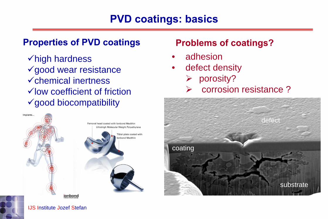
high hardnessgood wear resistance chemical inertness low coefficient of friction good biocompatibility
Properties of PVD coatings Problems of coatings?
substrate
coating
• adhesion• defect density
porosity?corrosion resistance ?
defect
IJS Institute Jozef Stefan

•Motivation•PVD Coatings•Corrosion resistance of PVD coating•Origin Growth defects in PVD coatings•Stylus profilometry •Focused ion beam•Conclusions
IJS Institute Jozef Stefan
Table of contents

IJS Institute Jozef Stefan
load
homogenous corosion
metal
attack
selective corrosion
porous Cu
brass (Cu-Zn)
Oxide layer
pit
pit corrosion
Crevise corrosion
narrow opening
erosive corrosion
flow
metalremoval
stress corrosion
stress
fatigue corrosion
cracks
stress
intercrystalline corrosion
intercrystalline attack
Types of corrosion
Corrosion is defined as a chemical and/or electrochemical reaction of metal with the environment, where the solid, soluble or gaseous products are formed.
There are different mechanisms of corrosion:
•uniform corrosion that takes place across the exposed surface
•local corrosion (e.g. pitting, crevise, selective), take place at specific places on the surface
•intercrystalline corrosion at grain boundaries
•stress corrosion cracking, observed on material exposed to a constant tensile stress in a corrosive environment

IJS Institute Jozef Stefan
e.g. Zn on Fe e.g. CrN on Fe; Ag on Fe
Types of coatings
covered by a coating
Ideal case real cases
As deposited
After exposedto corrosive media
More electroneg.coatingthen base material
Less electroneg.coatingthen base material

Corrosion testing by electrochemical methodes
• 3-electrode corrosion cell;WE electrode is multilayer structure substrate/coating/electrolyte
•corrosive media; •Hanks solution; bioapplication•0.1M NaCl solution; general corrosion
Methodes:• potentiodynamic measurements (PD)at dE/dt = 1 mV/s
•electrochemical impedance spectroscopy at opent circuit potential
IJS Institute Jozef Stefan

Potentiodynamic polarisation: measurement princip
Data from PD measurement:•Ecorr•jcorr •Eb
IJS Institute Jozef Stefan
Voltage is applied on (WE) and the current response is measured that occurs as a result of electrochemical reactions between the electrode and corrosive media.
log j
Pot
entia
l (E
) / V
EbdE/dt = 1 mV/s
E corr
jcorr
passive region-stable oxide film
transpassive region-after corrosion products have been formed
active region-dissolution
cathodic region

Potentiodynamic polarisation: results
•corrosive media; simulated physiolagical solution (Hanks) at room T; dE/dt = 1 mV/s
IJS Institute Jozef Stefan
1E-11 1E-10 1E-9 1E-8 1E-7 1E-6 1E-5 1E-4 1E-3 0,01 0,1
-0,5
0,0
0,5
1,0
1,5
2,0
E /V
vs
Ag/A
gCl
j/Acm-2
SS-316L
Ti/SS
3 kV2 kV
1 kV
DLC/Ti/SS
Ecorr more nobel material
icorrhigher corrosion resistance
Case: SS316L/Ti/DLC

substrate
coating
defect
IJS Institute Jozef Stefan
20μm
1E-10 1E-9 1E-8 1E-7 1E-6 1E-5 1E-4 1E-3 0.01 0.1 1
-1.0
-0.5
0.0
0.5
1.0
1.5TiAlN
CrCN
CrN mild steel (MS)E
/ V v
s A
g/A
gCl
j /Acm-2
Potentiodynamic polarisation: results
PVD hard coatings:
Ecorr more nobel material
icorrhigher corrosion resistance
corrosive media (general corrosion) 0.1M NaCldE/dt = 1 mV/s
Cases: (CrN, CrCN,TiAlN)/MS

substrate
IJS Institute Jozef Stefan
20μm
Electrochemical Impedance spectroscopy (EIS): princip
Principe of measurements:
AC potential applied
AC current responce
appl
ied
pote
ntia
l
current response
Impedance= AC resistor=Z(jω)

substrate
coating
defect
IJS Institute Jozef Stefan
20μm
0 20 40 60 80 100 1200
20
40
60
80
100
120
1h2h4h10h24h48h96h
-ZIm
/kΩ
ZRe/kΩ
0 1 2 3 40
1
2
3
4
Rp
Rpbetter corrosion properties
time Rp
Rpicorr
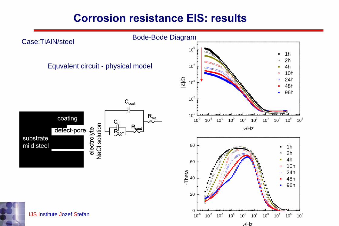
case:TiAlN/steel
Corrosion testing by EIS: results
Nyquist diagram
substrate
coating
defect
IJS Institute Jozef Stefan
20μm
10-3 10-2 10-1 100 101 102 103 104 105 1060
20
40
60
80
1h2h4h10h24h48h96h
1h2h4h10h24h48h96h
-The
ta
ν/Hz
10-3 10-2 10-1 100 101 102 103 104 105 106101
102
103
104
105
|Z|/Ω
ν/Hz
elec
troly
teN
aCl s
olut
ion
Ccoat
ReleCdl
RcorrRcoatdefect-pore
coating
substratemild steel
elec
troly
teN
aCl s
olut
ion
Ccoat
ReleCdl
RcorrRcoat
Ccoat
ReleCdl
RcorrRcoat
ReleCdl
RcorrRcoatdefect-pore
coating
substratemild steel
defect-pore
coating
substratemild steel
Bode-Bode Diagram
Equvalent circuit - physical model
Case:TiAlN/steel
Corrosion resistance EIS: results

substrate
coating
defect
IJS Institute Jozef Stefan
20μm
Imersion time/ h
Ecorr/mV
Qcoatμ/cm2s-nΩ
n Rcoat/ Ωcm2
Qdlμ/cm2s-nΩ
n Rcorr
/Ωcm2Rp
/Ωcm2
CrN/steel 1 -485 25.25 0.87 4450.2 14.54 0.80 4.64*103 9.09*103
10 -541 28.16 0.88 141.3 185.55 0.54 6.21*103 6.35*103
24 -565 63.12 0.81 139.7 339.23 0.56 4.72*103 4.87*103
48 -567 100.53 0.77 86.9 572.46 0.54 3.67*103 3.76*103
100 -570 256.98 0.67 90.6 834.55 0.57 2.29*103 2.39*103
Corrosion resistance EIS results
Values of fitted parameters (R, C) from equivalent circuit

A-1hA-96hB-1hB-96hC-1hC-96h
10-3 10-2 10-1 100 101 102 103 104 105 106101
102
103
104
105
106
107
|Z|/ Ω
ν/Hz
substrate
Impedance response of 316L/Ti/DLC-films in Hank solution; Bode-Bode Plot
10-3 10-2 10-1 100 101 102 103 104 105 1060
20
40
60
80
A-1hA-96hB-1hB-96hC-1hC-96h
substrate
-The
taν/Hz
IJS Institute Jozef Stefan
Corrosion resistance EIS: results

Impedance response of 316L/Cr/DLC‐films in Hank solution
0 2 4 6 80
2
4
6
8-Z
Im/Ω
cm
2
ZRe/Ω cm2 1kV-1h 1kV-96h3kV-1h3kV-96 2kV,N2-1h2kV, N2-96h
-ZIm
/ MΩ
cm
2
ZRe/ MΩ cm2
0 100 200 300 4000
200
400
600
800
0 10 20 30 40 500
20
40
nn jCQ −−= )( ω
n=1, Q reduces to an ideal capacitor
QDLC
RDLC
Rele
RDLC/electrolyte
QDLC/electroyte
ε=7.5
IJS Institute Jozef Stefan
Corrosion resistance EIS: results

Impedance response of multilayer structure 316L/Ti/DLC/electrolyte
Fitting with 2RQ term to determine resistance and capacitance properties of film,and film/electrolyte interface
nn jCQ −−= )( ω
n=1, Q reduces to an ideal capacitor
substrate
DLC film
TiQDLC
RDLC
Rele
RDLC/electrolyte
QDLC/electroyte
DLCelectroyte
IJS, Institute Jozef Stefan
Corrosion resistance EIS results

substrate
IJS Institute Jozef Stefan
20μm
• PVD coating i.e. transitional metal (Cr, Ti)- nitrides bellong to the nobel materials, thefore they are chemical inert
• At the defects, pitting corrosion is formed due to galvanic cell between substrate and more nobel coatings
•Changeing the EIS spectra (reducing R, increasing icorr) with time is due to reaction take place at the substrate/electrolyte interface
Corrosion resistance of PVD coatings

substrate
coating
defect
IJS Institute Jozef Stefan
20μm
All PVD coatings are microporous. Pores and other defects in the coating limit their corrosion resistance.
Corrosion resistance of PVD coating

coating defect
IJS Institute Jozef Stefan
20μm
Corrosion resistance of hard coatings can be improved by reducing of surface defect density; therefore the origin of defects should be analysed.
2 μm
1 μm1 µm1 µm 1 μm
2μm10 μm
Corrosion resistance of PVD coating

•Motivation•PVD Coatings•Corrosion resistance of PVD coating•Origin of growth defects in PVD coatings•Stylus profilometry •Focused ion beam•Conclusions
IJS Institute Jozef Stefan
Table of contents
IJS Institute Jozef Stefan
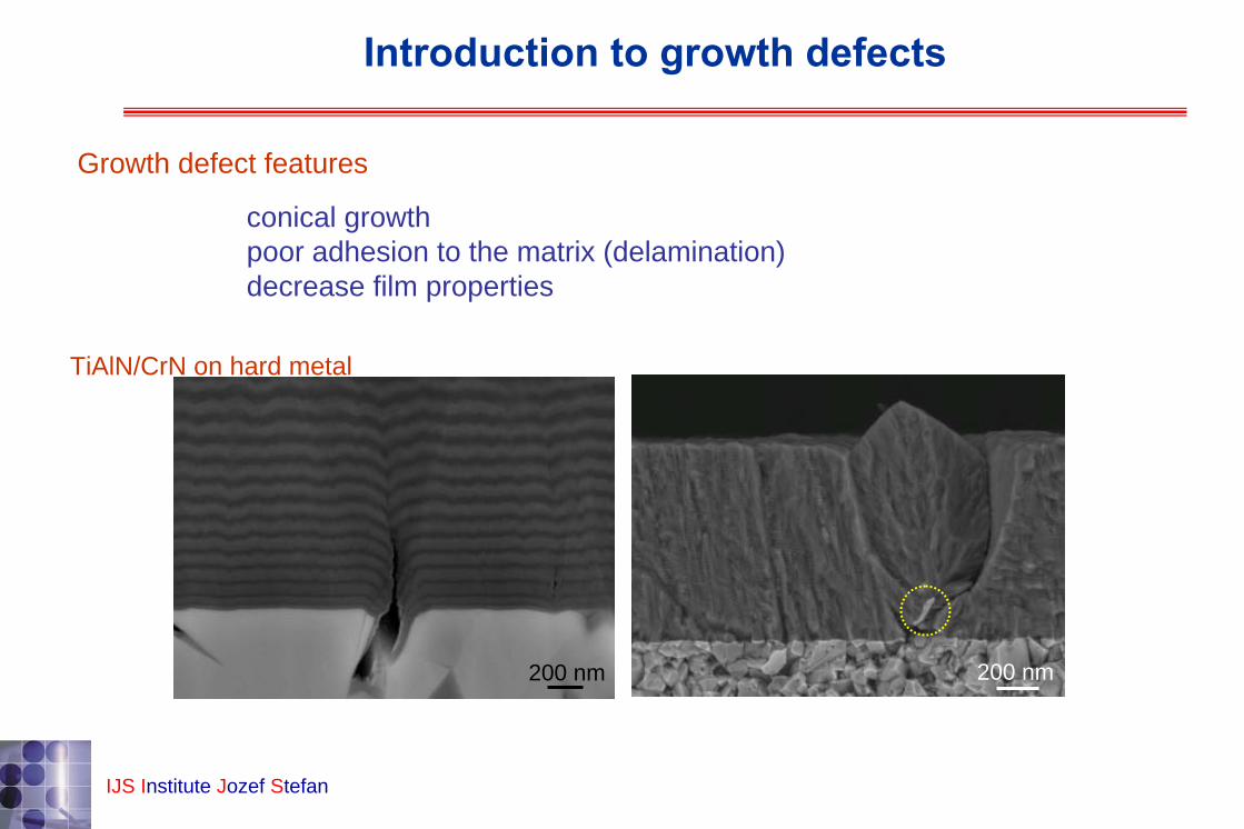
Introduction to growth defects
200 nm 200 nm
Growth defect features
conical growthpoor adhesion to the matrix (delamination)decrease film properties
TiAlN/CrN on hard metal

Intoduction to growth defects: defects origin
coating defect
IJS Institute Jozef Stefan
20μm
substrate imperfections
substrate contamination
film contamination(flaking, dust, abrasion, arcing) defect removal and regrowth

IJS Institute Jozef Stefan
after polishing after ion etching after deposition
Case: tool steel ASP30 + TiAlN coating
Substrate imperfections

IJS Institute Jozef Stefan
Substrate imperfections
10 µm
1 µm
500 nm
VC
steel
TiAlN
1 µmHM
AlTiN/TiN
1 µmD2
TiAlN
1 µmD2
TiAlN
valleys peaks
improperpolishing
pinholeformation
carbideinclusions

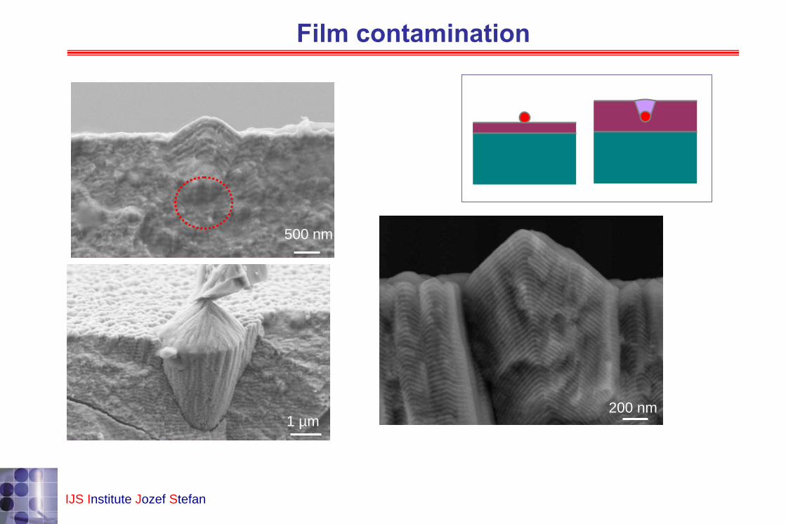
Substrate contamination
dustafter etchingshade effect
voids
IJS Institute Jozef Stefan
1 µm HM
CrN/TiAlN
1 µmCrN/TiAlN
D2 1 µmCrN/TiAlN
D2
5 µm
500 nm
1 µm
Film contamination
IJS Institute Jozef Stefan
200 nm

Defect removal and regrowth
IJS Institute Jozef Stefan
1 µm
1 µm
Growth defect study
What is the concentration of growth defects?What is the structure of growth defects?
density ≈ 100 mm–2

•Motivation•PVD Coatings•Corrosion resistance of PVD coating•Origin Growth defects in PVD coatings•Stylus profilometry •Focused ion beam•Conclusions
IJS Institute Jozef Stefan
Table of contents

stylus witha diamondtip
measurementdirection
sample
Stylus profilometry: experimental
0
0,1
0,2
0,3
0,4
0,5
0 0,2 0,4 0,6 0,8 1[mm]
[µm
]
IJS Institute Jozef Stefan
0,6
A common technique for evaluation of roughness

IJS Institute Jozef Stefan
sharp peak narrow trough
Features:insensitive to material type or colorslowproblems in sharp edges
Optical alternative:problem with dustsize of defects comparable to λ
Stylus profilometry: experimental

IJS Institute Jozef Stefan
resolution x: 0.2 µm
Y: 1 µmZ: few
nm
tip radius: 2 µmscanning area: 1 mm × 1 mmscanning time: 1.5 h
Acquired topography
growthdefect
film surface
x
y
substrate
film
growthdefect
Stylus profilometry: experimental

IJS Institute Jozef Stefan
Statistics
roughnessheight distribution of defectsnumber of peaks, valleys
Stylus profilometry: results
µm
-1
-0.8
-0.6
-0.4
-0.2
0
0.2
0.4
0.6
0.8
10 0.2 0.4 0.6 0.8 1 mm
mm
0
0.1
0.2
0.3
0.4
0.5
0.6
0.7
0.8
0.9
1
density ≈ 100 mm–2

•Motivation•PVD Coatings•Corrosion resistance of PVD coating•Origin Growth defects in PVD coatings•Stylus profilometry •Focused ion beam•Conclusions
IJS Institute Jozef Stefan
Table of contents

etching by Ga ions
A relatively new technique for observation of cross-sectionUsually integrated in a SEM
untreated surface observation by electrons
Focused ion beam: experimental
IJS Institute Jozef Stefan

Focused ion beam: experimental
10 µmfilmsubstr.
growth defectionetching
film
growth defect
substrate seed
substrate
film
growthdefect
Sample
FIB trough etching
SEM analysisIJS Institute Jozef Stefan

Focused ion beam: results
5 µmIJS Institute Jozef Stefan
CrN on Fe

IJS, Institute Jozef Stefan
Focused ion beam: results
5 µm 5 µm
CrNNi
Al alloy
CrN
2 µm 2 µm
TiAlN
steel
Fe
case 1CrN / Al alloy
case 2TiAlN / steel

IJS Institute Jozef Stefan
20 µm
2 µm 5 µm2 µm
5 µm2 µm
5µm10 µm
5 µm
a b
c d
Focused ion beam: results
TiAlN/on steel
•Motivation•PVD Coatings•Corrosion resistance of PVD coating•Origin Growth defects in PVD coatings•Stylus profilometry •Focused ion beam•Conclusions
IJS Institute Jozef Stefan
Table of contents

Corrosion resistance of PVD coating
Conclusions
IJS Institute Jozef Stefan
Potentiodynamic measurementsCorrosion potentialCorrosion current density(corrosion rate)Break down potential Destructive methode
Electrochemical impedance spectroscopy
Corrosion potential, corrosion rateProperties of coating/electrolyte and substrate/electrolyte interfaceModeling neccessaryNon-destructive methode
Take-home messagePVD coatings are microporous, pore and defects limit the corrosion resistanceRcorr can be improved by: interlayer, thickness, multilayer, nanocomposite etc.

Conclusions
IJS Institute Jozef Stefan
Stylus profilometrygrowth defect densitystatistical nature time consuming
Focused ion beamanalysis of one defect onlycomplete structure of the growth defectEDS: chemical composition of the seed
Take-home message
do not underestimate the role of growth defect in PVD coatingscarefully prepare the substrates and keep the lab hygene
Growth Defects in PVD coating
IJS Institute Jozef Stefan
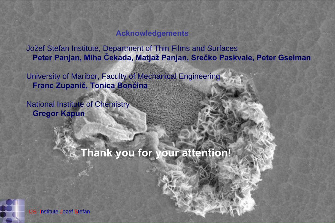
Thank you for your attention!
Jožef Stefan Institute, Department of Thin Films and SurfacesPeter Panjan, Miha
Čekada, Matjaž
Panjan, Srečko Paskvale, Peter Gselman
University of Maribor, Faculty of Mechanical EngineeringFranc Zupanič, Tonica
Bončina
National Institute of ChemistryGregor Kapun
Acknowledgements