RoHS 2 Compliant - OMEGA Engineering meter is an economical Miniature Temperature Panel Thermometer...
22
Where Do I Find Everything I Need for Process Measurement and Control? OMEGA…Of Course! Shop on line at www.omega.com TEMPERATURE Thermocouple, RTD & Thermistor Probes, Connectors, Panels & Assemblies Wire: Thermocouple, RTD & Thermistor Calibrators & Ice Point References Recorders, Controllers & Process Monitors Infrared Pyrometers PRESSURE, STRAIN AND FORCE Transducers & Strain Gauges Load Cells & Pressure Gauges Displacement Transducers Instrumentation & Accessories FLOW/LEVEL Rotameters, Gas Mass Flowmeters & Flow Computers Air Velocity Indicators Turbine/Paddlewheel Systems Totalizers & Batch Controllers pH/CONDUCTIVITY pH Electrodes, Testers & Accessories Benchtop/Laboratory Meters Controllers, Calibrators, Simulators & Pumps Industrial pH & Conductivity Equipment DATA ACQUISITION Data Acquisition & Engineering Software Communications-Based Acquisition Systems Plug-in Cards for Apple, IBM & Compatibles Datalogging Systems Recorders, Printers & Plotters HEATERS Heating Cable Cartridge & Strip Heaters Immersion & Band Heaters Flexible Heaters Laboratory Heaters ENVIRONMENTAL MONITORING AND CONTROL Metering & Control Instrumentation Refractometers Pumps & Tubing Air, Soil & Water Monitors Industrial Water & Wastewater Treatment pH, Conductivity & Dissolved Oxygen Instruments M1189/0605 11231ML-98D DP116 Thermocouple Miniature Panel Thermometer User’s Guide ™ ® Shop on line at www.omega.com e-mail: [email protected] RoHS 2 Compliant
-
Upload
duongduong -
Category
Documents
-
view
214 -
download
1
Transcript of RoHS 2 Compliant - OMEGA Engineering meter is an economical Miniature Temperature Panel Thermometer...

Where Do I Find Everything I Need for Process Measurement and Control?
OMEGA…Of Course!Shop on line at www.omega.comTEMPERATURE Thermocouple, RTD & Thermistor Probes, Connectors, Panels & Assemblies Wire: Thermocouple, RTD & Thermistor Calibrators & Ice Point References Recorders, Controllers & Process Monitors Infrared Pyrometers
PRESSURE, STRAIN AND FORCE Transducers & Strain Gauges Load Cells & Pressure Gauges Displacement Transducers Instrumentation & Accessories
FLOW/LEVEL Rotameters, Gas Mass Flowmeters & Flow Computers Air Velocity Indicators Turbine/Paddlewheel Systems Totalizers & Batch Controllers
pH/CONDUCTIVITY pH Electrodes, Testers & Accessories Benchtop/Laboratory Meters Controllers, Calibrators, Simulators & Pumps Industrial pH & Conductivity Equipment
DATA ACQUISITION Data Acquisition & Engineering Software Communications-Based Acquisition Systems Plug-in Cards for Apple, IBM & Compatibles Datalogging Systems Recorders, Printers & Plotters
HEATERS Heating Cable Cartridge & Strip Heaters Immersion & Band Heaters Flexible Heaters Laboratory Heaters
ENVIRONMENTALMONITORING AND CONTROL Metering & Control Instrumentation Refractometers Pumps & Tubing Air, Soil & Water Monitors Industrial Water & Wastewater Treatment pH, Conductivity & Dissolved Oxygen Instruments
M1189/0605 11231ML-98D
DP116Thermocouple Miniature
Panel Thermometer
User’s Guide
™
®
Shop on line at
www.omega.come-mail: [email protected]
RoHS 2 Compliant

It is the policy of OMEGA to comply with all worldwide safety and EMC/EMI regulations that apply. OMEGA is constantly pursuing certification of its products to the European NewApproach Directives. OMEGA will add the mark to every appropriate device upon certification.
The information contained in this document is believed to be correct, but OMEGA Engineering, Inc. accepts no liability for any errors it contains, and reserves the right to alter specifications without notice.
WARNING: These products are not designed for use in, and should not be used for, patient-connected applications.
This device is marked with the international caution symbol. It is important to read the Setup Guide before installing or commissioning this device as the guide contains importantinformation relating to safety and EMC.
This device is marked with the international caution symbol. It is important to read the Setup Guide before installing or commissioning this device as the guide containsimportant information relating to safety and EMC.!
Servicing North America:USA: One Omega Drive, P.O. Box 4047ISO 9001 Certified Stamford CT 06907-0047
TEL: (203) 359-1660 FAX: (203) 359-7700e-mail: [email protected]
Canada: 976 Bergar Laval (Quebec) H7L 5A1 TEL: (514) 856-6928 FAX: (514) 856-6886
e-mail: [email protected]
For immediate technical or application assistance:USA and Canada: Sales Service: 1-800-826-6342 / 1-800-TC-OMEGA®
Customer Service: 1-800-622-2378 / 1-800-622-BEST®
Engineering Service: 1-800-872-9436 / 1-800-USA-WHEN®
Mexico and TEL: (001)800-TC-OMEGA® FAX: (001) 203-359-7807 Latin America: En Español: (001) 203-359-7803
e-mail: [email protected]
Servicing Europe:Benelux: Postbus 8034, 1180 LA Amstelveen, The Netherlands
TEL: +31 20 3472121 FAX: +31 20 6434643 Toll Free in Benelux: 0800 0993344
e-mail: [email protected]
Czech Republic: Frystatska 184, 733 01 Karviná TEL: +420 59 6311899 FAX: +420 59 6311114
e-mail: [email protected]
France: 11, rue Jacques Cartier, 78280 Guyancourt TEL: +33 1 61 37 29 00 FAX: +33 1 30 57 54 27 Toll Free in France: 0800 466 342
e-mail: [email protected]
Germany/Austria: Daimlerstrasse 26, D-75392 Deckenpfronn, Germany TEL: +49 7056 9398-0 FAX: +49 7056 9398-29 Toll Free in Germany: 0800 639 7678
e-mail: [email protected]
United Kingdom: One Omega DriveISO 9002 Certified River Bend Technology Centre
Northbank, Irlam Manchester M44 5BD United Kingdom TEL: +44 161 777 6611 FAX: +44 161 777 6622 Toll Free in England: 0800 488 488
e-mail: [email protected]
OMEGAnet® On-Line Servicewww.omega.com
Internet [email protected]
®
®
WARRANTY/DISCLAIMEROMEGA ENGINEERING, INC. warrants this unit to be free of defects in materials and workmanship for aperiod of 13 months from the date of purchase. OMEGA’s Warranty adds an additional one (1) monthgrace period to the normal one (1) year product warranty to cover handling and shipping time. Thisensures that OMEGA’s customers receive maximum coverage on each product.
If the unit malfunctions, it must be returned to the factory for evaluation. OMEGA’s Customer ServiceDepartment will issue an Authorized Return (AR) number immediately upon phone or written request.Upon examination by OMEGA, if the unit is found to be defective, it will be repaired or replaced at nocharge. OMEGA’s WARRANTY does not apply to defects resulting from any action of the purchaser,including but not limited to mishandling, improper interfacing, operation outside of design limits, improperrepair, or unauthorized modification. This WARRANTY is VOID if the unit shows evidence of having beentampered with or shows evidence of having been damaged as a result of excessive corrosion; or current,heat, moisture or vibration; improper specification; misapplication; misuse or other operating conditionsoutside of OMEGA’s control. Components which wear are not warranted, including but not limited tocontact points, fuses, and triacs.
OMEGA is pleased to offer suggestions on the use of its various products. However, OMEGAneither assumes responsibility for any omissions or errors nor assumes liability for any damagesthat result from the use of its products in accordance with information provided by OMEGA,either verbal or written. OMEGA warrants only that the parts manufactured by it will be asspecified and free of defects. OMEGA MAKES NO OTHER WARRANTIES OR REPRESENTATIONSOF ANY KIND WHATSOEVER, EXPRESS OR IMPLIED, EXCEPT THAT OF TITLE, AND ALL IMPLIEDWARRANTIES INCLUDING ANY WARRANTY OF MERCHANTABILITY AND FITNESS FOR APARTICULAR PURPOSE ARE HEREBY DISCLAIMED. LIMITATION OF LIABILITY: The remedies ofpurchaser set forth herein are exclusive, and the total liability of OMEGA with respect to thisorder, whether based on contract, warranty, negligence, indemnification, strict liability orotherwise, shall not exceed the purchase price of the component upon which liability is based. Inno event shall OMEGA be liable for consequential, incidental or special damages.
CONDITIONS: Equipment sold by OMEGA is not intended to be used, nor shall it be used: (1) asa “Basic Component” under 10 CFR 21 (NRC), used in or with any nuclear installation or activity; or(2) in medical applications or used on humans. Should any Product(s) be used in or with any nuclearinstallation or activity, medical application, used on humans, or misused in any way, OMEGAassumes no responsibility as set forth in our basic WARRANTY/DISCLAIMER language, and,additionally, purchaser will indemnify OMEGA and hold OMEGA harmless from any liability ordamage whatsoever arising out of the use of the Product(s) in such a manner.
RETURN REQUESTS/INQUIRIESDirect all warranty and repair requests/inquiries to the OMEGA Customer Service Department.BEFORE RETURNING ANY PRODUCT(S) TO OMEGA, PURCHASER MUST OBTAIN ANAUTHORIZED RETURN (AR) NUMBER FROM OMEGA’S CUSTOMER SERVICE DEPARTMENT(IN ORDER TO AVOID PROCESSING DELAYS). The assigned AR number should then be markedon the outside of the return package and on any correspondence.The purchaser is responsible for shipping charges, freight, insurance and proper packaging toprevent breakage in transit.
FOR WARRANTY RETURNS, please have the following information available BEFORE contacting OMEGA:1. Purchase Order number under which the product
was PURCHASED,2. Model and serial number of the product under
warranty, and3. Repair instructions and/or specific problems
relative to the product.
FOR NON-WARRANTY REPAIRS, consultOMEGA for current repair charges. Have thefollowing information available BEFOREcontacting OMEGA:1. Purchase Order number to cover the COST
of the repair,2. Model and serial number of product, and3. Repair instructions and/or specific problems
relative to the product.
OMEGA’s policy is to make running changes, not model changes, whenever an improvement is possible. This affordsour customers the latest in technology and engineering.OMEGA is a registered trademark of OMEGA ENGINEERING, INC.© Copyright 2003 OMEGA ENGINEERING, INC. All rights reserved. This document may not be copied, photocopied,reproduced, translated, or reduced to any electronic medium or machine-readable form, in whole or in part, without theprior written consent of OMEGA ENGINEERING, INC.
It is the policy of OMEGA to comply with all worldwide safety and EMC/EMI regulations that apply. OMEGA is constantly pursuing certification of its products to the European NewApproach Directives. OMEGA will add the CE mark to every appropriate device upon certification.
The information contained in this document is believed to be correct, but OMEGA Engineering, Inc. accepts no liability for any errors it contains, and reserves the right to alterspecifications without notice.
WARNING: These products are not designed for use in, and should not be used for, patient-connected applications.
This device is marked with the international caution symbol. It is important to read the Setup Guide before installing or commissioning this device as the guide contains importantinformation relating to safety and EMC.
This device is marked with the international caution symbol. It is important to read the Setup Guide before installing or commissioning this device as the guide containsimportant information relating to safety and EMC.!
Servicing North America:USA: One Omega Drive, P.O. Box 4047ISO 9001 Certified Stamford CT 06907-0047
TEL: (203) 359-1660 FAX: (203) 359-7700 e-mail: [email protected]
Canada: 976 Bergar Laval (Quebec) H7L 5A1
TEL: (514) 856-6928 FAX: (514) 856-6886 e-mail: [email protected]
For immediate technical or application assistance:USA and Canada: Sales Service: 1-800-826-6342 / 1-800-TC-OMEGA®
Customer Service: 1-800-622-2378 / 1-800-622-BEST®
Engineering Service: 1-800-872-9436 / 1-800-USA-WHEN®
Mexico and TEL: (001)800-TC-OMEGA® FAX: (001) 203-359-7807 Latin America: En Español: (001) 203-359-7803
e-mail: [email protected]
Servicing Europe:Benelux: Postbus 8034, 1180 LA Amstelveen, The Netherlands
TEL: +31 20 3472121 FAX: +31 20 6434643Toll Free in Benelux: 0800 0993344
e-mail: [email protected]
Czech Republic: Frystatska 184, 733 01 KarvináTEL: +420 59 6311899 FAX: +420 59 6311114
e-mail: [email protected]
France: 11, rue Jacques Cartier, 78280 GuyancourtTEL: +33 1 61 37 29 00 FAX: +33 1 30 57 54 27Toll Free in France: 0800 466 342e-mail: [email protected]
Germany/Austria: Daimlerstrasse 26, D-75392 Deckenpfronn, GermanyTEL: +49 7056 9398-0 FAX: +49 7056 9398-29Toll Free in Germany: 0800 639 7678
e-mail: [email protected]
United Kingdom: One Omega DriveISO 9002 Certified River Bend Technology Centre
Northbank, Irlam Manchester M44 5BD United Kingdom TEL: +44 161 777 6611 FAX: +44 161 777 6622Toll Free in England: 0800 488 488
e-mail: [email protected]
OMEGAnet® On-Line Servicewww.omega.com
Internet [email protected]
®
®
WARRANTY/DISCLAIMEROMEGA ENGINEERING, INC. warrants this unit to be free of defects in materials and workmanship for aperiod of 13 months from the date of purchase. OMEGA’s Warranty adds an additional one (1) monthgrace period to the normal one (1) year product warranty to cover handling and shipping time. Thisensures that OMEGA’s customers receive maximum coverage on each product.
If the unit malfunctions, it must be returned to the factory for evaluation. OMEGA’s Customer ServiceDepartment will issue an Authorized Return (AR) number immediately upon phone or written request.Upon examination by OMEGA, if the unit is found to be defective, it will be repaired or replaced at nocharge. OMEGA’s WARRANTY does not apply to defects resulting from any action of the purchaser,including but not limited to mishandling, improper interfacing, operation outside of design limits, improperrepair, or unauthorized modification. This WARRANTY is VOID if the unit shows evidence of having beentampered with or shows evidence of having been damaged as a result of excessive corrosion; or current,heat, moisture or vibration; improper specification; misapplication; misuse or other operating conditionsoutside of OMEGA’s control. Components which wear are not warranted, including but not limited tocontact points, fuses, and triacs.
OMEGA is pleased to offer suggestions on the use of its various products. However, OMEGAneither assumes responsibility for any omissions or errors nor assumes liability for any damagesthat result from the use of its products in accordance with information provided by OMEGA,either verbal or written. OMEGA warrants only that the parts manufactured by it will be asspecified and free of defects. OMEGA MAKES NO OTHER WARRANTIES OR REPRESENTATIONSOF ANY KIND WHATSOEVER, EXPRESS OR IMPLIED, EXCEPT THAT OF TITLE, AND ALL IMPLIEDWARRANTIES INCLUDING ANY WARRANTY OF MERCHANTABILITY AND FITNESS FOR APARTICULAR PURPOSE ARE HEREBY DISCLAIMED. LIMITATION OF LIABILITY: The remedies ofpurchaser set forth herein are exclusive, and the total liability of OMEGA with respect to thisorder, whether based on contract, warranty, negligence, indemnification, strict liability orotherwise, shall not exceed the purchase price of the component upon which liability is based. Inno event shall OMEGA be liable for consequential, incidental or special damages.
CONDITIONS: Equipment sold by OMEGA is not intended to be used, nor shall it be used: (1) asa “Basic Component” under 10 CFR 21 (NRC), used in or with any nuclear installation or activity; or(2) in medical applications or used on humans. Should any Product(s) be used in or with any nuclearinstallation or activity, medical application, used on humans, or misused in any way, OMEGAassumes no responsibility as set forth in our basic WARRANTY/DISCLAIMER language, and,additionally, purchaser will indemnify OMEGA and hold OMEGA harmless from any liability ordamage whatsoever arising out of the use of the Product(s) in such a manner.
RETURN REQUESTS/INQUIRIESDirect all warranty and repair requests/inquiries to the OMEGA Customer Service Department.BEFORE RETURNING ANY PRODUCT(S) TO OMEGA, PURCHASER MUST OBTAIN ANAUTHORIZED RETURN (AR) NUMBER FROM OMEGA’S CUSTOMER SERVICE DEPARTMENT(IN ORDER TO AVOID PROCESSING DELAYS). The assigned AR number should then be markedon the outside of the return package and on any correspondence.The purchaser is responsible for shipping charges, freight, insurance and proper packaging toprevent breakage in transit.
FOR WARRANTY RETURNS, please have the following information available BEFORE contacting OMEGA:1. Purchase Order number under which the product
was PURCHASED,2. Model and serial number of the product under
warranty, and3. Repair instructions and/or specific problems
relative to the product.
FOR NON-WARRANTY REPAIRS, consultOMEGA for current repair charges. Have thefollowing information available BEFOREcontacting OMEGA:1. Purchase Order number to cover the COST
of the repair,2. Model and serial number of product, and3. Repair instructions and/or specific problems
relative to the product.
OMEGA’s policy is to make running changes, not model changes, whenever an improvement is possible. This affordsour customers the latest in technology and engineering.OMEGA is a registered trademark of OMEGA ENGINEERING, INC.© Copyright 2003 OMEGA ENGINEERING, INC. All rights reserved. This document may not be copied, photocopied,reproduced, translated, or reduced to any electronic medium or machine-readable form, in whole or in part, without theprior written consent of OMEGA ENGINEERING, INC.

TTAABBLLEE OOFF CCOONNTTEENNTTSS
SSEECCTTIIOONN PPAAGGEEPreface . . . . . . . . . . . . . . . . . . . . . . . . . . . . . . . . .ii
Models Available . . . . . . . . . . . . . . . . . . . . . . . . . .iii
Section 1 Introduction . . . . . . . . . . . . . . . . . . . . . . . . . . . . . .1
1.1 Unpacking . . . . . . . . . . . . . . . . . . . . . . . . . . . . . . .1
1.2 Safety Considerations . . . . . . . . . . . . . . . . . . . . . .2
Section 2 About the Meter . . . . . . . . . . . . . . . . . . . . . . . . . . .3
2.1 Front of the Meter . . . . . . . . . . . . . . . . . . . . . . . . .3
2.2 Back of the Meter . . . . . . . . . . . . . . . . . . . . . . . . .4
2.3 Description . . . . . . . . . . . . . . . . . . . . . . . . . . . . . .4
Section 3 Getting Started . . . . . . . . . . . . . . . . . . . . . . . . . . .5
3.1 Main Board Power Jumpers . . . . . . . . . . . . . . . . . .5
3.2 Converting °F to °C (vice versa) . . . . . . . . . . . . . . .7
3.3 Installation and Panel Mounting . . . . . . . . . . . . . . .8
3.4 Sensor Input Connections . . . . . . . . . . . . . . . . . .10
3.5 Analog Output Connections . . . . . . . . . . . . . . . . .12
3.6 Display Hold Connections . . . . . . . . . . . . . . . . . .13
3.7 Main Power Connections . . . . . . . . . . . . . . . . . . .14
3.8 Disassembly/Assembly . . . . . . . . . . . . . . . . . . . .16
Section 4 Operation and Calibration . . . . . . . . . . . . . . . . . .18
4.1 Equipment Required . . . . . . . . . . . . . . . . . . . . . .18
4.2 Calibration Procedure . . . . . . . . . . . . . . . . . . . . .19
Section 5 Specifications . . . . . . . . . . . . . . . . . . . . . . . . . . . .28
Section 6 Glossary . . . . . . . . . . . . . . . . . . . . . . . . . . . . . . .32
i
ii
PREFACE
Manual Objectives: This manual shows you how to set up anduse the Panel Thermometer.
This meter is an economical Miniature Temperature PanelThermometer featuring a large display with a linearized analogoutput that is supplied as a standard feature.
Each of the models* can be converted by the user to display indegrees Fahrenheit or Celsius. However, due to the internaldesign of the meter, the input type and resolution CANNOTbe changed on any J, K, T, or E unit.
The meter is available in many different styles. All of theThermocouple models listed in Table 1-1 come standard withred LEDs, and can be ordered with a green LED display as anoption. The part numbers would then end with “-GR”.
Example: DP116-JF1-GR
Also, these thermocouple meters can be ordered with differentpower configurations. Refer to Table 1-3 for available choices.
*Refer to Table 1-1 for the complete listing of models available.

32
SSEECCTTIIOONN 66 GGLLOOSSSSAARRYY
COMMON MODE REJECTION (CMR) - a measure of the affectof a voltage on the indicated display. It is the ratio of thecommon mode voltage to the measured voltage due to acommon mode voltage.
COMMON MODE VOLTAGE (CMV) - the average of thevoltage applied to both wires of a two wire or differential input.
NORMAL MODE REJECTION (NMR) - a measure of therejection of unwanted signal due to a voltage applied betweenthe wires of a two wire or differential input (shown as normalmode voltage). NMR is the ratio of the normal mode voltage tothe measured voltage due to the normal mode voltage.
TEMPCO - abbreviation for temperature coefficient. It is theeffect of changes in ambient temperature on a particularparameter, such as zero or span settings.
iii
TABLE 1-1
TTCC MMOODDEELLSS AAVVAAIILLAABBLLEE
The accuracies and ranges are listed in Section 5.
The following 3-1/2 digit mini thermocouple panelthermometers are discussed in this operator’s manual.
MODEL TYPE °C or °F RESOLUTION
DP116-JF1 J F 1.0°FDP116-JF2 J F 0.1°FDP116-JC1 J C 1.0°CDP116-JC2 J C 0.1°C
DP116-KF1 K F 1.0°FDP116-KF2 K F 0.1°FDP116-KC1 K C 1.0°CDP116-KC2 K C 0.1°C
DP116-TF1 T F 1.0°FDP116-TF2 T F 0.1°FDP116-TC1 T C 1.0°CDP116-TC2 T C 0.1°C
DP116-EF1 E F 1.0°FDP116-EF2 E F 0.1°FDP116-EC1 E C 1.0°CDP116-EC2 E C 0.1°C

iv
Table 1-2
OOtthheerr MMooddeellss AAvvaaiillaabbllee
Table 1-3
PPoowweerr OOppttiioonnss AAvvaaiillaabblleeMODEL POWER
DP116-TC type 115 Vac ±15%, 50/60 Hz
DP116-TC type-230 230 Vac ±15%, 50/60 Hz
DP116-TC type-9/26 9-26 Vdc @ 110mA max, non-isolated.Use ungrounded Thermocouplesto avoid ground loops.
DP116-TC type-100 100 Vac ±15%, 50/60 Hz
DP116-TC type-24 24 Vac ±15%, 50/60 Hz
The following 3-1/2 digit mini RTD panel meters are availableand discussed in a separate RTD Operator’s Manual.
MODEL TYPE °C or °F RESOLUTION
DP116-MF1 RTD F 1.0°FDP116-MF2 RTD F 0.1°FDP116-MC1 RTD C 1.0°CDP116-MC2 RTD C 0.1°C
31
TABLE 5-1
ACCURACY/RANGE TABLE
* Look at Table 1-1, for complete models (preface section).
MODEL MAXIMUMOPTION ERROR RANGE RESOLUTION
*-JF1 2.7°F -346 to +1400°F 1.0°F*-JF2 1.8°F -199.9 to +199.9°F 0.1°F*-JC1 1.5°C -210 to +760°C 1.0°C*-JC2 1.0°C -199.9 to +199.9°C 0.1°C
*-KF1 2.7°F -157 to +1999°F 1.0°F*-KF2 1.8°F -199.9 to +199.9°F 0.1°F*-KC1 1.5°C -105 to +1372°C 1.0°C*-KC2 1.0°C -199.9 to +199.9°C 0.1°C
*-TF1 2.7°F -157 to +752°F 1.0°F*-TF2 1.8°F -199.9 to +199.9°F 0.1°F*-TC1 1.5°C -105 to +400°C 1.0°C*-TC2 1.0°C -199.9 to +199.9°C 0.1°C
*-EF1 2.7°F -157 to +1832°F 1.0°F*-EF2 1.8°F -199.9 to+199.9°F 0.1°F*-EC1 1.5°C -105 to +1000°C 1.0°C*-EC2 1.0°C -199.9 to+199.9°C 0.1°C

30
TOP VIEWSIDE VIEW
0.858 [21.80] 2.661[67.60]
4.60[116.8]
4.134[105.00]
0.197[5.00]
0.945 [24.00] 2.835 [72.00]
PANEL CUTOUT
0.25 [6.4] MAX0.03 [0.8] MIN
PANEL THICKNESS
0.874 +.012/-.000[22.20 +0.30/-0.00]
R 0.06 [1.5]4 PLCS
[68.00 +0.70/-0.00]2.677 +0.028/-.000
Figure 5-1 Dimensions
v
NNOOTTEESS,, WWAARRNNIINNGGSS aanndd CCAAUUTTIIOONNSS
Information that is especially important to note is identified bythese labels:
NOTE: provides you with information that is important tosuccessfully setup and use the Programmable DigitalMeter.
CAUTION or WARNING: tells you about the risk ofelectric shock.
CAUTION, WARNING or IMPORTANT: tells you ofcircumstances or practices that can effect the meter'sfunctionality and must refer to accompanyingdocuments.

29
DISPLAY Type:..........................................................................................7-segment, LEDHeight: .......................................................................................0.56" (14.2 mm)Symbols:..................................................................................................-1.8.8.8Overrange Indication:....................................Three least-significant digits blankColors: .........................................................................................Red - standard
Green - optional
DIGITAL INPUTSHold:......................................................................TTL or 5V CMOS compatible
ENVIRONMENTALOperating Temperature: ...............................................0° to 60°C(32° to 140°F)Storage Temperature: .............................................-40° to 85°C (-40° to 185°F)Relative Humidity: ..............................................95% at 40°C (non-condensing)
MECHANICAL DIMENSIONSBezel: .......................................................................0.94" x 2.83" (24 x 72 mm)Depth Behind the Bezel: .....................................4.72" (120 mm) w/ connectors Panel Cutout: .................................................0.87"H x 2.68" W (22.2 x 68 mm)Weight: .............................................................................7 ounces (200 grams)Panel Thickness.........................................................minimum: 0.03" (0.76mm)
maximum: 0.25" (6.25mm)Case Material: ......................................................94V-1 UL-rated thermoplastic
POWERAC Frequency: ......................................................................................50/60 HzMax. Power: .................................................................................2.4 watts max.AC Voltage: ................................................................115Vac ±15% 25mA max.
230Vac ±15% 14mA max.100Vac ±15% 30mA max.24Vac ±15% 127mA max.
DC Voltage:..........................................................................9-26 Vdc @ 110mA
External Fuse Protection needed:...................................32mA, 115Vac/230VacUL Slow-blow (per single unit) 40mA, 100Vac
160mA, 24Vac125mA, 9-26Vdc
Installation Category: .................................................................. I per EN61010Equipment Class: .........................................................................I per EN61010Pollution Degree: ........................................................................2 per EN61010
† Refer to the Glossary in Section 6.

28
SSEECCTTIIOONN 55 SSPPEECCIIFFIICCAATTIIOONNSS
INPUT TYPE:Thermocouple: ..........................................J,K,T, or E (Chromel-Constantan)Calibration:.....................................................................IEC 584-1 (IPTS-68)Configuration: .............Single-ended (-TC lead connected to Analog Return)Polarity:................................................................................................BipolarCold-junction Tempco: ...............................................................±0.1 deg/deg
Sensor-wire resistance effect per conductor:Type E: 50 µdeg/deg/Ω, up to 2000Ω
Sensor-break Current:.........................................................................333 nASensor-break Indication: ...........Meter displays positive overrange (upscale)
NOISE REJECTIONNMR†, SIG HI to SIG LO: ....................................................70 dB, 50/60 HzCMR†, Analog RTN to PWR GND: ...............................120 dB, DC to 60 HzCMV†, Analog RTN to PWR GND: ...................Dielectric strength to 1500 V
transient per 260 Volt rms or DC working voltage.
ACCURACY at 25°CRange for rated accuracyThermocouple Type: ..........................................................Refer to Table 5-1Maximum Error: .................................................................Refer to Table 5-1Resolution: .........................................................................Refer to Table 5-1Span Tempco: ..............................................................±0.02% of reading/°CFull-Scale Step Response: ....................................................................... 1 sWarmup to Rated Accuracy: .............................................................. 30 min.
ANALOG OUTPUT (linearized)Voltage:..........................................................................................1mV/countCalibration Error:..................................................... ±1% of reading ± 1.0mV
on °C, ± 1.8mV on °FSource Resistance: ................................................................................100Ω
ANALOG TO DIGITAL CONVERSIONTechnique:.............................................................Dual-slope, average valueSignal Integration Period: ...................................................................100 msRead Rate:..............................................................................................2.5/s
1
SSEECCTTIIOONN 11 IINNTTRROODDUUCCTTIIOONN
11..11 UUNNPPAACCKKIINNGG
Remove the Packing List and verify that all equipment has beenreceived. If there are any questions about the shipment, use thephone numbers listed on the back cover to contact theCustomer Service Department nearest you.
Upon receipt of shipment, inspect the container and equipmentfor any signs of damage. Take particular note of any evidenceof rough handling in transit. Immediately report any damage tothe shipping agent.
The carrier will not honor any claims unless all shippingmaterial is saved for their examination. After examiningand removing contents, save packing material andcarton in the event reshipment is necessary.
Verify that you received the following items in the shipping box:
QTY DESCRIPTION
1 Panel Thermometer with 3 small connectors pluggedinto the rear of the meter.
1 Operator’s Manual

2
11..22 SSAAFFEETTYY CCOONNSSIIDDEERRAATTIIOONNSS
This device is marked with the international Caution symbol. It is important to read thismanual before installing or commissioning this device as it contains importantinformation relating to Safety and EMC (Electromagnetic Compatibility).
Unpacking & InspectionUnpack the instrument and inspect for obvious shipping damage. Do not attempt tooperate the unit if damage is found.
This instrument is a panel mount device protected in accordance with Class I of EN 61010(115/230 AC power connections). Installation of this instrument should be done byQualified personnel. In order to ensure safe operation, the following instructions shouldbe followed.
This instrument has no power-on switch. An external switch or circuit-breaker shall be included inthe building installation as a disconnecting device. It shall be marked to indicate this function, andit shall be in close proximity to the equipment within easy reach of the operator. The switch orcircuit-breaker shall not interrupt the Protective Conductor (Earth wire), and it shall meet therelevant requirements of IEC 947–1 and IEC 947-3 (International Electrotechnical Commission).The switch shall not be incorporated in the mains supply cord.
Furthermore, to provide protection against excessive energy being drawn from the mains supplyin case of a fault in the equipment, an overcurrent protection device shall be installed.
• The Protective Conductor must be connected for safety reasons. Check that the powercable has the proper Earth wire, and it is properly connected. It is not safe to operatethis unit without the Protective Conductor Terminal connected.
• Do not exceed voltage rating on the label located on the top of the instrumenthousing.
• Always disconnect power before changing signal and power connections.• Do not use this instrument on a work bench without its case for safety reasons.• Do not operate this instrument in flammable or explosive atmospheres.• Do not expose this instrument to rain or moisture.• Unit mounting should allow for adequate ventilation to ensure instrument does not
exceed operating temperature rating.• Use electrical wires with adequate size to handle mechanical strain and power
requirements. Install without exposing bare wire outside the connector to minimizeelectrical shock hazards.
EMC Considerations• Whenever EMC is an issue, always use shielded cables.• Never run signal and power wires in the same conduit.• Use signal wire connections with twisted-pair cables.• Install Ferrite Bead(s) on signal wires close to the instrument if EMC problems
persist.
27
TABLE 4-2 (Cont’d)
† The best MID-RANGE accuracy is obtained when themeter is calibrated to the exact values shown in column 3,even though a small error may occur at 32°F (0°C).
* Look at Table 1-1, for complete models (preface section).
MILLIVOLTMODEL VALUE FROM METER POT TOOPTION MILLIVOLT DISPLAY ADJUST
SOURCE
*-TF1 0.0 31°F † Zero19.638 716°F Span
*-TF2 0.0 32.0°F Zero3.584 185.0°F Span
*-TC1 0.0 0°C Zero19.638 380°C Span
*-TC2 0.0 0.0°C Zero8.495 185.0°C Span
*-EF1 0.0 31°F † Zero73.727 1769°F Span
*-EF2 0.0 33.0°F † Zero5.130 180.0°F Span
*-EC1 0.0 0°C Zero73.727 965°C Span
*-EC2 0.0 0.5°C † Zero12.314 185.0°C Span

26
TABLE 4-2
CALIBRATION VALUES WHEN USING A MILLIVOLT SOURCE
† Look at the end of Table 4-2, for the explanation of †.* Look at Table 1-1, for complete models (preface section).
MILLIVOLT MODEL VALUE FROM METER POT TOOPTION MILLIVOLT DISPLAY ADJUST
SOURCE
*-JF1 0.0 32°F Zero41.013 1346°F Span
*-JF2 0.0 31.6°F † Zero3.917 167.0°F Span
*-JC1 0.0 0°C Zero41.013 730°C Span
*-JC2 0.0 -0.2°C † Zero9.113 170.0°C Span
*-KF1 0.0 31°F † Zero40.449 1794°F Span
*-KF2 0.0 32.0°F Zero2.896 160.0°F Span
*-KC1 0.0 0°C Zero53.611 1335°C Span
*-KC2 0.0 0.0°C Zero7.737 190.0°C Span
3
SSEECCTTIIOONN 22 AABBOOUUTT TTHHEE MMEETTEERR
22..11 FFrroonntt ooff tthhee MMeetteerr
Figure 2-1 shows the panel thermometer.
Figure 2-1. Panel Thermometer
Features:
Display: 3 1/2 Digit, 7-Segment Red or Green LEDFull-size 14.2 mm (0.56") LED DisplayAnalog Output Standard3/64 DIN Standard Panel CutoutRemovable Screw-Clamp Cable ConnectorDisplay Hold Capability

4
22..22 BBaacckk ooff tthhee MMeetteerr
Figure 2-2 illustrates the rear of the meter.
Figure 2-2. Rear View Showing P1, P2, P3 Connectors
22..33 CCoonnnneeccttoorr DDeessccrriippttiioonn
† For wire colors, refer to Table 3-1
CCoonnnneeccttoorr DDeessccrriippttiioonn CCoonnnneeccttoorr PPIINN ##((AACC)) EEaarrtthh GGrroouunndd PP11 11((AACC)) NNeeuuttrraall PP11 22((AACC)) LLiinnee PP11 33((DDCC)) --DDCC RReettuurrnn PP11 11((DDCC)) ++DDCC PP11 22((DDCC)) NNoo CCoonnnneeccttiioonn ((NNoott uusseedd)) PP11 33DDiissppllaayy HHoolldd ((AAccttiivvee LLooww)) PP22 11RReettuurrnn PP22 22AAnnaalloogg OOuuttppuutt PP22 33--TTCC ((NNeegg.. LLeeaadd)) † PP33 11++TTCC ((PPooss.. LLeeaadd)) † PP33 22
P1 P2 P3
1 2 3 1 2 3 1 2
25
3. Connect the power to the meter. Refer to theappropriate model number in Table 4-2 for the propercalibration points for your particular meter.
4. Adjust the millivolt source to output the millivolt valueshown on the first line of column 2. Check to see that themeter displays the temperature indicated in column 3. Ifnot, adjust the zero potentiometer until it reads thatsimulated value. For example, if the meter has a "-JC2"in the model number, set the millivolt source for 0.0 andthe meter display should show 0°C.
5. Adjust the millivolt source to output the millivolt valueshown on the second line of column 2. Check to see thatthe meter displays that same value. If not adjust the spanpot until it reads that simulated value. For example, if themeter has a "-JC1" in the model number, set the millivoltsource for 41.013 and the meter display should show730°C.

24
4.2.2 Calibrating using a Millivolt Source
1. Disconnect the power from the meter. Remove thefront lens. Notice the the zero potentiometer is locatedto the left of the display and the span potentiometer islocated to the right of the display.
Refer to Figure 4-1 for the location of the calibrationpots.
2. Connect the millivolt source to the MCJ Electronic IcePoint or ice bath which in turn connects to thethermocouple input connector P3 as shown in Figure4-3. Connect the negative (red) thermocouple wire toconnector P3, Pin 1. Connect the positivethermocouple wire to connector P3, Pin 2. Be sure toobserve polarity and use the correct thermocouplewire (Type J wire for Type J meter).
Figure 4-3. Calibration with a Millivolt Source
METER
P3
P2
P1
T/C WIRE
mV SOURCE
COPPER WIRE
ICE BATH
AC
METER
P3
P2
P1
T/C WIRE
AC
mV SOURCE
COPPER WIRE
OMEGAMCJ
OMEGATRP PROBE
5
SSEECCTTIIOONN 33 GGEETTTTIINNGG SSTTAARRTTEEDD
33..11 MMaaiinn BBooaarrdd PPoowweerr JJuummppeerrss
Caution: The meter has no power-on switch, so it will bein operation as soon you apply power.
The meter can be configured to operate on 115 Vac or230 Vac by the proper combination of the soldered wirejumpers that are located on the printed circuit board. Themeter is set at the factory to be powered by the voltagespecified at the time of ordering. The same transformer isused for either configuration, so all you need to do is toselect the jumpers as described in this section.
IImmppoorrttaanntt:: These changes must be performed by aqualified technician.
To change the Factory preset jumpers, do the following steps:
Disconnect the power from the unit before proceeding.
1. Remove the main board from the case. Refer toDisassembly/Assembly Section 3.8.
2. Locate the solder jumpers W1, W2, and W3 (located nearthe edge of the main board alongside the transformer).
3. If your power requirement is 115 Vac, solder jumpers W1and W3 should be wired, but jumper W2 should not. Ifyour power requirement is 230 Vac, solder jumper W2should be wired, but jumpers W1 and W3 should not.

6
Voltage Jumper Pin Settings
Figure 3-1 shows the location of solder jumpers W1 through W3.
Figure 3-1. PC Board Jumper Locations
S3
P3
P1
W1 W2 W3
2
1
2
3
1
TRANSFORMER
SPAN
DIS
PLA
Y
ZERO
(COMPONENT SIDE)
P2 2
3
1
AC VOLTAGE INSTALL REMOVE115 Vac W1, W3 W2230 Vac W2 W1, W3
23
TABLE 4-1 (Cont’d)
† The best MID-RANGE accuracy is obtained when themeter is calibrated to the exact values shown in column 3,even though a small error may occur at 32°F (0°C).
* Look at Table 1-1, for complete models (preface section).
MODEL T/C CALIBRATOR METER POT TOOPTION DISPLAY ADJUST DISPLAY
*-TF1 32°F 31°F † Zero716°F 716°F Span
*-TF2 32.0°F 32.0°F Zero185.0°F 185.0°F Span
*-TC1 0°C 0°C Zero380°C 380°C Span
*-TC2 0.0°C 0.0°C Zero185.0°C 185.0°C Span
*-EF1 32°F 31°F † Zero1769°F 1769°F Span
*-EF2 32.0°F 33.0°F † Zero180.0°F 180.0°F Span
*-EC1 0°C 0°C Zero965°C 965°C Span
*-EC2 0°C 0.5°C † Zero185.0°C 185.0°C Span

22
TABLE 4-1
CALIBRATION VALUES WHEN USINGTHERMOCOUPLE CALIBRATOR
† Look at the end of Table 4-1 for the explanation of †.* Look at Table 1-1, for complete models (preface section).
MODEL T/C CALIBRATOR METER POT TOOPTION DISPLAY DISPLAY ADJUST
*-JF1 32°F 32°F Zero1346°F 1346°F Span
*-JF2 32.0°F 31.6°F † Zero167.0°F 167.0°F Span
*-JC1 0°C 0°C Zero730°C 730°C Span
*-JC2 0.0°C -0.2°C † Zero170.0°C 170.0°C Span
*-KF1 32°F 31°F † Zero1794°F 1794°F Span
*-KF2 32.0°F 32.0°F Zero160.0°F 160.0°F Span
*-KC1 0°C 0°C Zero1335°C 1335°C Span
*-KC2 0.0°C 0.0°C Zero190.0°C 190.0°C Span
7
33..22 CCoonnvveerrttiinngg °°FF ttoo °°CC ((vviiccee vveerrssaa))You must remove the printed circuit board from the casein order to change from the Fahrenheit to Celsius (or viceversa). This change must be performed by a qualifiedtechnician in order to avoid damage to the unit.Disconnect the power from the unit before proceeding.
Degrees Fahrenheit and degrees Celsius are selectableparameters. All you need to do is change the location of theshorting jumper at S3, using needle-nose pliers.
1. Disconnect all wiresand move the unitfrom the panel (ifinstalled).
2. Remove the printedcircuit board fromthe case asdescribed inSection 3-8.
3. Follow the instructions to convert to:Celsius: .The unit will display degrees Celsius when the shorting jumperis connected to both pins at S3. Refer to Figure 3-2, Detail A.
Fahrenheit: .The unit will display degrees Fahrenheit if the shorting jumperat S3 is NOT connecting the 2 pins. Refer to Figure 3-2,Detail B. By keeping the shorting jumper on one pin, you arekeeping it handy in case you want to change the display backto degrees C.
Figure 3-2. S3 Jumper
DETAIL A DETAIL B
SHORTINGJUMPER
FOR °C FOR °F
S3
S3S3
P3
P1
W1 W2 W3
2
1
2
3
1
TRANSFORMER
SPAN
DIS
PLA
Y
ZERO
(COMPONENT SIDE)
P2 2
3
1

8
SSeeccttiioonn 33..33 IInnssttaallllaattiioonn aanndd PPaanneell MMoouunnttiinngg
Figure 3-3 shows the panel cutout dimensions, the dimensionsfor the panel thickness, and the mounting clamp for mountingthe unit in a panel. Connections will be done after mountingthe unit.
1. Remove the lens by inserting a paper clip or a small flatblade screwdriver into the rounded corner of the lens and liftout.
2. Remove the two mounting screws from both sides of thedisplay. Pry both sides of the mounting clamp out and downto remove it from the meter case.
3. Insert the meter into the panel cutout and reinstall themounting clamp to the bottom of the meter case from therear of the panel.
4. Re-install the mounting screws to secure the meter in thepanel. Do not over-tighten the screws.
5. Pop the lens back in, making sure the dull side of the lensfaces towards you.
21
4. Set the thermocouple calibrator to match thethermocouple type of your meter. Adjust thethermocouple calibrator to output the temperatureshown in the first line of column 2. Check to see thatthe unit displays the temperature shown in column 3.If not, adjust the zero potentiometer until it reads thatsimulated value. For example, if the meter has a"-JC2" in the model number, set the calibrator for0.0°C and the unit display should show -0.2°C.
5. Adjust the thermocouple calibrator to output thetemperature shown in the second line of column 2.Check to see that the unit displays the temperatureshown in column 2. If not, adjust the span pot until itreads that simulated value. For example, if the meterhas a "-JC2" in the model number, set the calibrator for170.0°C and the meter display should show 170.0°C.
6. After adjusting the pots, go back and verify bothtemperature readings. Repeat steps 4 and 5 asrequired.

20
2. Connect the thermocouple calibrator output signal tothe thermocouple input connector P3 as shown inFigure 4-2. Connect the negative (red) thermocouplewire to connector P3, Pin 1. Connect the positivethermocouple wire to connector P3, Pin 2. Be sure toobserve polarity and use the correct thermocouplewire (Type J wire for Type J meter).
Figure 4-2. Calibration a Thermocouple Calibrate
3. Connect the power to the meter. Allow 30 minutewarm up before calibration of 0.1° resolution meters.Refer to the appropriate model number in Table 4-1for the proper calibration points for your particularmeter.
METER
P3
P2
P1
T/C WIRE
AC
T/C CALIBRATOR
0°C
9
Figure 3-3. Installation Information
PANEL CUTOUT
PANEL CUTOUT
CASE
0.25 [6.4] MAX0.03 [0.8] MIN
PANEL THICKNESS
0.874 +.012/-.000[22.20 +0.30/-0.00]
R 0.06 [1.5]4 PLCS
[68.00 +0.70/-0.00]2.677 +0.028/-.000
MOUNTINGSCREW HOLES
MOUNTING SCREW (2)
MOUNTING CLAMP
LENS
CLAMP
CLAMPSCREWS
S1
SZ

10
33..44 SSeennssoorr IInnppuutt CCoonnnneeccttiioonnssTable 3-1. AMERICAN (USA) THERMOCOUPLE WIRE COLORS
The meter is configured at the factory for the desiredthermocouple type (J, K, T, E) and the desired units of measure(°C or °F), as defined by the customer at the time of purchase.
The meter configuration is defined in the part number. Forexample, a Type T meter that reads in degrees Fahrenheitwould have a "-TF2" in the part number. The “1” at the end ofthe part number indicates a 1 degree resolution and “2” at theend of the part number indicates a 0.1 degree resolution. SeeTable 1-1 for model number listing.
Once the meter is configured for a particularthermocouple type, it CANNOT be changed to accept anyother input type. It becomes dedicated to thatthermocouple type as ordered.
TT//CC ""++"" LLEEAADD WWIIRREE ""--"" LLEEAADD WWIIRREETTYYPPEE AALLLLOOYY//WWIIRREE CCOOLLOORR AALLLLOOYY//WWIIRREE CCOOLLOORRJJ IIrroonn ((wwhhiittee)) CCoonnssttaannttaann ((rreedd))KK CChhrroommeell ((yyeellllooww)) AAlluummeell ((rreedd))TT CCooppppeerr ((bblluuee)) CCoonnssttaannttaann ((rreedd))EE CChhrroommeell ((ppuurrppllee)) CCoonnssttaannttaann ((rreedd))
19
Meter calibration must be performed using athermocouple calibrator. If a millivolt source is usedinstead, be sure to connect the output of the millivoltsource to an Omega MCJ Electronic Ice Point (orequivalent) of the appropriate thermocouple type (or anice bath). Doing this will compensate for the cold junctionerrors.
4.2 CALIBRATION PROCEDURE
Refer to Section 4.2.1 for details on how to calibrate themeter using the Thermocouple Calibrator. Refer to Section4.2.2 for details on how to calibrate the meter using theMillivolt Source.
4.2.1 Thermocouple Calibrating
1. Disconnect the power from the meter. Remove thefront lens. Notice the the zero potentiometer (pot) islocated to the left of the display and the spanpotentiometer is located to the right of the display.
Refer to Figure 4-1 for the location of the calibrationpots.
Figure 4-1. Calibration Potentiometers
ZERO SPAN

18
SSEECCTTIIOONN 44 OOPPEERRAATTIIOONN AANNDD CCAALLIIBBRRAATTIIOONN
IImmppoorrttaanntt:: These changes must be performed by aqualified technician.
WARNING: Do not connect ac power to your meter untilyou have completed all input and output connections.Failure to do so may result in injury!
1. Wire the meter according to the wiring section. Thisincludes power, thermocouple and analog signalconnections.
2. Apply power to the meter and the display will show thetemperature of the probe.
The meter is shipped from the factory calibrated to the accuracyas specified. No re-calibration is necessary. In the event thatthere is a desire to check the calibration, the followingprocedure is given.
4.1 EQUIPMENT REQUIRED• Meter• Extension grade thermocouple wire• a small screwdriver• a precision Thermocouple Calibrator
OR• a precision Millivolt Source (0.001 resolution)
used in conjunction with an Electronic Ice Point • copper wire
OR• a precision Millivolt Source (0.001 resolution)
used in conjunction with an ice bath• copper wire
11
33..44 SSeennssoorr IInnppuutt CCoonnnneeccttiioonnss ((CCoonnttiinnuueedd))
To connect the input to the unit, attach the thermocouple probe tothe 2-pin female connector that is supplied with the unit. Refer toFigure 3-4 for wiring instructions and Table 2-1 for wire colors.
Plug the female connector into the P3 male connector at therear of the meter.
Figure 2-2 shows the location of the P3 connector on the meter.
Figure 3-4. Thermocouple Connector Wiring (P3)
12
– TC INPUT
Screwsunderneath
+ TC INPUT
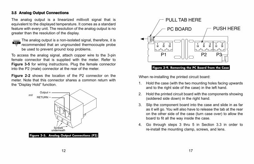
12
33..55 AAnnaalloogg OOuuttppuutt CCoonnnneeccttiioonnss
The analog output is a linearized millivolt signal that isequivalent to the displayed temperature. It comes as a standardfeature with every unit. The resolution of the analog output is nogreater than the resolution of the display.
The analog output is a non-isolated signal, therefore, it isrecommended that an ungrounded thermocouple probebe used to prevent ground loop problems.
To access the analog signal, attach copper wire to the 3-pinfemale connector that is supplied with the meter. Refer toFigure 3-5 for wiring instructions. Plug the female connectorinto the P2 (male) connector at the rear of the meter.
Figure 2-2 shows the location of the P2 connector on themeter. Note that this connector shares a common return withthe “Display Hold” function.
Figure 3-5. Analog Output Connections (P2)
12
3
RETURN
Screwsunderneath
Output +mV
–
17
Figure 3-9. Removing the PC Board from the Case
When re-installing the printed circuit board:
1. Hold the case (with the two mounting holes facing upwardsand to the right side of the case) in the left hand.
2. Hold the printed circuit board with the components showing(soldered side down) in the right hand.
3. Slip the component board into the case and slide in as faras it will go. You will also have to release the tab at the rearon the other side of the case (turn case over) to allow theboard to fit all the way inside the case.
4. Go through steps 3 thru 5 in Section 3.3 in order tore-install the mounting clamp, screws, and lens.
PC BOARD
PULL TAB HERE
PUSH HERE
P1 P2 P3
1 2 3 1 2 3 1 2
12
33..55 AAnnaalloogg OOuuttppuutt CCoonnnneeccttiioonnss
The analog output is a linearized millivolt signal that isequivalent to the displayed temperature. It comes as a standardfeature with every unit. The resolution of the analog output is nogreater than the resolution of the display.
The analog output is a non-isolated signal, therefore, it isrecommended that an ungrounded thermocouple probebe used to prevent ground loop problems.
To access the analog signal, attach copper wire to the 3-pinfemale connector that is supplied with the meter. Refer toFigure 3-5 for wiring instructions. Plug the female connectorinto the P2 (male) connector at the rear of the meter.
Figure 2-2 shows the location of the P2 connector on themeter. Note that this connector shares a common return withthe “Display Hold” function.
Figure 3-5. Analog Output Connections (P2)
12
3
RETURN
Screwsunderneath
Output +mV
–
17
Figure 3-9. Removing the PC Board from the Case
When re-installing the printed circuit board:
1. Hold the case (with the two mounting holes facing upwardsand to the right side of the case) in the left hand.
2. Hold the printed circuit board with the components showing(soldered side down) in the right hand.
3. Slip the component board into the case and slide in as faras it will go. You will also have to release the tab at the rearon the other side of the case (turn case over) to allow theboard to fit all the way inside the case.
4. Go through steps 3 thru 5 in Section 3.3 in order tore-install the mounting clamp, screws, and lens.
PC BOARD
PULL TAB HERE
PUSH HERE
P1 P2 P3
1 2 3 1 2 3 1 2

16
33..88 DDiissaasssseemmbbllyy//AAsssseemmbbllyy
You must go through the following steps in order toremove the printed circuit board from the case if youwant to change from 115 Vac to 230 Vac (or vice versa)or to change from Fahrenheit to Celsius (or vice versa).These changes must be performed by a qualifiedtechnician in order to avoid damage to the unit.
WARNING: Do not connect ac power to your meter untilyou have completed all input and output connections.Failure to do so may result in injury!
1. Remove power and all wire connections from the unit.
2. Unplug the three connectors (P1, P2, and P3) from theback of the meter. Grasp them firmly on the top andbottom of the connector and pull. Figure 3-9 shows thelocation of the three connectors.
3. Remove the lens, mounting screws, and mounting clampfrom the unit as described in steps 1 and 2 in Section 3.Slide the unit out of the panel (if it is installed in a panel).
4. The printed circuit board is held in place by a tab andnotch system located next to the P1 connector, pin 1(refer to Figure 3-9). The tab is on the case and thenotch is on the edge of the PC Board. Hold the meterwith the display facing away from you. Gently pry the tab(on the back corner of the case) out with the edge of yourfinger, while pushing the back of the PC Board outthrough the front of the meter. The PC Board will slideout the front, free from the case.
13
33..66 DDiissppllaayy HHoolldd CCoonnnneeccttiioonnss
The “Display Hold” function can be used to freeze the display.Connect a single pole, single throw (SPST) switch betweenpins 1 and 2 on the P2 connector. The display will stopupdating when this switch is on. When this switch is off, thedisplay will update itself 2.5 times per second.
To access the “Display Hold” function, attach copper wire tothe 3-pin female connector that is supplied with the meter.Refer to Figure 3-6 for wiring instructions. This connectorshares a common return with the Analog Output. Plug thefemale connector into the P2 connector at the rear of themeter. Figure 2-2 shows the location of the P2 connector onthe meter.
Figure 3-6. Display Hold Connections
12
3
RETURN
Screwsunderneath
Display HoldSwitch
P2
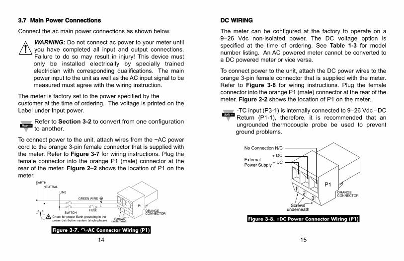
14
33..77 MMaaiinn PPoowweerr CCoonnnneeccttiioonnss
Connect the ac main power connections as shown below.
WARNING: Do not connect ac power to your meter untilyou have completed all input and output connections.Failure to do so may result in injury! This device mustonly be installed electrically by specially trainedelectrician with corresponding qualifications. The mainpower input to the unit as well as the AC input signal to bemeasured must agree with the wiring instruction.
The meter is factory set to the power specified by thecustomer at the time of ordering. The voltage is printed on theLabel under Input power.
Refer to Section 3-2 to convert from one configurationto another.
To connect power to the unit, attach wires from the ~AC powercord to the orange 3-pin female connector that is supplied withthe meter. Refer to Figure 3-7 for wiring instructions. Plug thefemale connector into the orange P1 (male) connector at therear of the meter. Figure 2–2 shows the location of P1 on themeter.
Figure 3-7. ~~AC Connector Wiring (P1)
FUSE
GREEN WIRE
EARTH
Screwsunderneath
ORANGECONNECTOR
P1
©NL
12
3SWITCH
LINE
NEUTRAL
Check for proper Earth grounding in the power distribution system (single phase).
15
DDCC WWIIRRIINNGG
The meter can be configured at the factory to operate on a9–26 Vdc non-isolated power. The DC voltage option isspecified at the time of ordering. See Table 1-3 for modelnumber listing. An AC powered meter cannot be converted toa DC powered meter or vice versa.
To connect power to the unit, attach the DC power wires to theorange 3-pin female connector that is supplied with the meter.Refer to Figure 3-8 for wiring instructions. Plug the femaleconnector into the orange P1 (male) connector at the rear of themeter. Figure 2-2 shows the location of P1 on the meter.
-TC input (P3-1) is internally connected to 9–26 Vdc –DCReturn (P1-1), therefore, it is recommended that anungrounded thermocouple probe be used to preventground problems.
Figure 3-8. =DC Power Connector Wiring (P1)
12
3
– DC
Screwsunderneath
+ DC
No Connection N/C
P1ORANGECONNECTOR
ExternalPower Supply