ROEVER ENGINEERING COLLEGE DEPARTMENT … ENGINEERING COLLEGE DEPARTMENT OF ECE EC2352-COMPUTER...
63
ROEVER ENGINEERING COLLEGE DEPARTMENT OF ECE EC2352-COMPUTER NETWORKS PREPARED BY K.BALAJI, ME., AP/ECE
Transcript of ROEVER ENGINEERING COLLEGE DEPARTMENT … ENGINEERING COLLEGE DEPARTMENT OF ECE EC2352-COMPUTER...

ROEVER ENGINEERING COLLEGE DEPARTMENT OF ECE
EC2352-COMPUTER NETWORKS
PREPARED BY
K.BALAJI, ME., AP/ECE
UNIT-I
PHYSICAL LAYER
1. Define data communication.
It is the exchange of data between two devices via some form of Transmission medium ( such as copper cable,twisted pair cable etc).
2. What are the elements of data communication?
The elements of data communication are
Sender
Receiver
Transmission medium
Message
Protocol
3. How we can check the effectiveness of data communication?
The effectiveness of data communication can be checked by
Accuracy
Delivery
Timeliness
4. What are the classes of transmission media?
The classes of transmission media are
Guided transmission media
Unguided transmission media
5. Define Optical fiber
It is a method of transmitting information from one place to another by sending light through an optical fiber.
6. Define distributed processing
A task is divided among multiple computers. Instead of single large machine handling all the process, each separate computer handles the subset
7. What do you mean by OSI?
Open system interconnection model is a model for understanding and designing a network architecture. It is not a protocol.

8. Define Network.
A network is a set of devices connected by physical media links. A network is
recursively is a connection of two or more nodes by a physical link or two or more networks
connected by one or more nodes
9. What is a Link? At the lowest level, a network can consist of two or more computers directly
connected by some physical medium such as coaxial cable or optical fiber. Such a physical
medium is called as Link.
10 What is point-point link?
If the physical links are limited to a pair of nodes it is said to be point-point link.
11. What is Multiple Access?
If the physical links are shared by more than two nodes, it is said to be Multiple
Access.
12. Define Switch
Switches are hardware or software devices capable of creating temporary Connections
between two or more devices
13. What are the types of switching?
The types of switching are
Circuit switching
Packet switching
Message switching 14. What do you mean by Crossbar switches?
It connects m inputs to n outputs in a grid using electronic micro switches at
each cross points.
15. Define Blocking
The reduction in the number of cross points result in a phenomenon called
Blocking

16. Define packet switching
In packet switching data are transmitted in discrete units of potentially
variable length blocks called Packets
17. What are the approaches of packet switching?
The approaches of packet switching are
Virtual circuit
Datagram 18. What do you mean by Permanent Virtual circuit?
The same Virtual circuit is provided between two users on a continuous
basis. The circuit is dedicated to the specific user
19. What do you mean by DSL?
It is a new technology that uses the existing telecommunication network to
accomplish high speed delivery of data, voice & video etc.
20. What is the purpose of Physical layer?
The physical layer coordinates the functions required to transmit a bit stream
over a physical medium.
PART-B
DEFINE ISO-OSI LAYER?
ISO-OSI 7-Layer Network Architecture This lecture introduces the ISO-OSI layered architecture of Networks. According to the ISO
standards, networks have been divided into 7 layers depending on the complexity of the
functionality each of these layers provide. The detailed description of each of these layers is given
in the notes below. We will first list the layers as defined by the standard in the increasing order of
function complexity: 1. Physical Layer 2. Data Link Layer 3. Network Layer 4. Transport Layer 5. Session Layer 6. Presentation Layer 7. Application Layer
Physical Layer This layer is the lowest layer in the OSI model. It helps in the transmission of data between two

machines that are communicating through a physical medium, which can be optical fibres,copper
wire or wireless etc. The following are the main functions of the physical layer: 1. Hardware Specification: The details of the physical cables, network interface cards, wireless
radios, etc are a part of this layer.
Network Layer Its basic functions are routing and congestion control. Routing: This deals with determining how
packets will be routed (transferred) from source to destination. It can be of three types: 15. Static: Routes are based on static tables that are "wired into" the network and are rarely
changed. 16. Dynamic: All packets of one application can follow different routes depending upon the
topology of the network, the shortest path and the current network load. 17. Semi-Dynamic: A route is chosen at the start of each conversation and then all the packets
of the application follow the same route.
Transport Layer Its functions are: 1. Multiplexing / Demultiplexing : Normally the transport layer will create distinct network
connection for each transport connection required by the session layer. The transport layer may
either create multiple network connections (to improve throughput) or it may multiplex several
transport connections onto the same network connection (because creating and maintaining
networks may be expensive). In the latter case, demultiplexing will be required at the receiving end.
A point to note here is that communication is always carried out between two processes and not
between two machines. This is also known as process-to-process communication. 2. Fragmentation and Re-assembly: The data accepted by the transport layer from the session
layer is split up into smaller units (fragmentation) if needed and then passed to
the network layer. Correspondingly, the data provided by the network layer to the transport layer on
the receiving side is re-assembled.
Presentation Layer This layer is concerned with the syntax and semantics of the information transmitted. In order to
make it possible for computers with different data representations to communicate data structures to
be exchanged can be defined in abstract way along with standard encoding. It also manages these
abstract data structures and allows higher level of data structures to be defined an exchange. It
encodes the data in standard agreed way (network format). Suppose there are two machines A and B
one follows 'Big Endian' and other 'Little Endian' for data representation. This layer ensures that the
data transmitted by one gets converted in the form compatible to other machine. This layer is
concerned with the syntax and semantics of the information transmitted. In order to make it possible
for computers with different data representations to communicate data structures to be exchanged
can be defined in abstract way along with standard encoding. It also manages these abstract data
structures and allows higher level of data structures to be defined an exchange. Other functions
include compression, encryption etc.
Application Layer The seventh layer contains the application protocols with which the user gains access to the
network. The choice of which specific protocols and their associated functions are to be used at the
application level is up to the individual user. Thus the boundary between the presentation layer and
the application layer represents a separation of the protocols imposed by the network designers from
those being selected and implemented by the network users. For example commonly used protocols
are HTTP(for web browsing), FTP(for file transfer) etc.
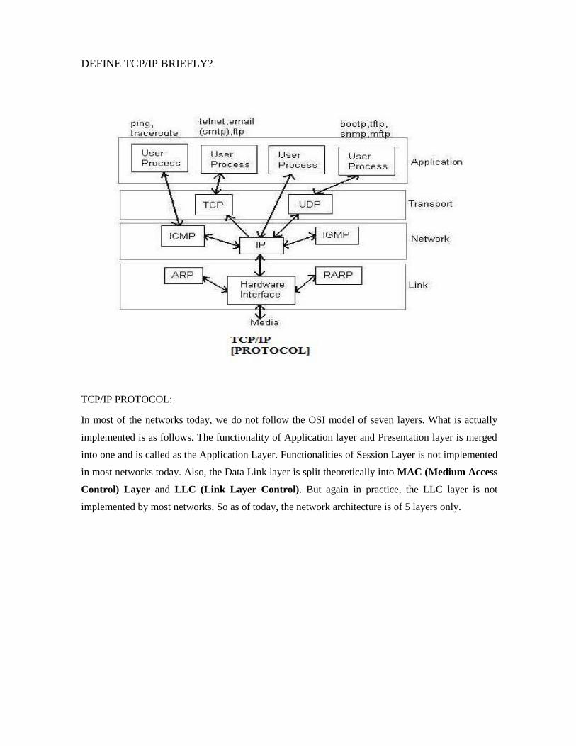
DEFINE TCP/IP BRIEFLY?
TCP/IP PROTOCOL: In most of the networks today, we do not follow the OSI model of seven layers. What is actually
implemented is as follows. The functionality of Application layer and Presentation layer is merged
into one and is called as the Application Layer. Functionalities of Session Layer is not implemented
in most networks today. Also, the Data Link layer is split theoretically into MAC (Medium Access
Control) Layer and LLC (Link Layer Control). But again in practice, the LLC layer is not
implemented by most networks. So as of today, the network architecture is of 5 layers only.

DEFINE GUIDED AND UNGUIDED TRANSMISSION MEDIA?
GUIDED AND UNGUIDED TRANSMISSION MEDIA:
Physical layer is concerned with transmitting raw bits over a communication channel. The design
issues have to do with making sure that when one side sends a 1 bit, it is received by the other side
as 1 bit and not as 0 bit. In physical layer we deal with the communication medium used for
transmission. Types of Medium Medium can be classified into 2 categories. 1. Guided Media: Guided media means that signals is guided by the prescence of physical media
i.e. signals are under control and remains in the physical wire. For eg. copper wire 2. Unguided Media: Unguided Media means that there is no physical path for the signal to
propagate. Unguided media are essentially electro-magnetic waves. There is no control on flow of
signal. For eg. radio waves. Communication Links In a network nodes are connected through links. The communication through links can be classified
as 1. Simplex: Communication can take place only in one direction. eg. T.V broadcasting. 2. Half-duplex: Communication can take place in one direction at a time. Suppose node A and B
are connected then half-duplex communication means that at a time data can flow from A to B or
from B to A but not simultaneously. eg. two persons talking to each other such that when speaks the
other listens and vice versa. 3. Full-duplex: Communication can take place simultaneously in both directions. eg. A discussion
in a group without discipline. Links can be further classified as 1. Point to Point: In this communication only two nodes are connected to each other. When a node
sends a packet then it can be received only by the node on the other side and none else. 2. Multipoint: It is a kind of sharing communication, in which signal can be recieved by all nodes.
This is also called broadcast. Generally two kind of problems are associated in transmission of signals. 1. Attenuation: When a signal transmits in a network then the quality of signal degrades as the
signal travels longer distances in the wire. This is called attenuation. To improve quality of signal
amplifiers are used at regular distances. 2. Noise: In a communication channel many signals transmit simultaneously, certain random signals
are also present in the medium. Due to interference of these signals our signal gets disrupted a bit. Bandwidth Bandwidth simply means how many bits can be transmitted per second in the communication

channel. In technical terms it indicates the width of frequency spectrum. Transmission Media Guided Transmission Media In Guided transmission media generally two kind of materials are used. 1. Copper o Coaxial Cable o Twisted Pair 2. Optical Fiber 1. Coaxial Cable: Coaxial cable consists of an inner conductor and an outer conductor which are seperated by an insulator. The inner conductor is usually copper. The outer conductor is covered by
a plastic jacket. It is named coaxial because the two conductors are coaxial. Typical diameter of
coaxial cable lies between 0.4 inch to 1 inch. The most application of coaxial cable is cable T.V.
The coaxial cable has high bandwidth, attenuation is less.
Twisted Pair: A Twisted pair consists of two insulated copper wires, typically 1mm thick. The
wires are twisted togather in a helical form the purpose of twisting is to reduce cross talk
interference between several pairs. Twisted Pair is much cheaper then coaxial cable but it is
susceptible to noise and electromagnetic interference and attenuation is large.

Twisted Pair can be further classified in two categories: Unshielded twisted pair: In this no
insulation is provided, hence they are susceptible to interference. Shielded twisted pair: In this a
protective thick insulation is provided but shielded twisted pair is expensive and not commonly
used. The most common application of twisted pair is the telephone system. Nearly all telephones
are connected to the telephone company office by a twisted pair. Twisted pair can run several
kilometers without amplification, but for longer distances repeaters are needed. Twisted pairs can be
used for both analog and digital transmission. The bandwidth depends on the thickness of wire and
the distance travelled. Twisted pairs are generally limited in distance, bandwidth and data rate.
3. Optical Fiber: In optical fiber light is used to send data. In general terms presence of light is
taken as bit 1 and its absence as bit 0. Optical fiber consists of inner core of either glass or plastic.
Core is surrounded by cladding of the same material but of different refractive index. This cladding
is surrounded by a plastic jacket which prevents optical fiber from electromagnetic interference and
harshly environments. It uses the principle of total internal reflection to transfer data over optical
fibers. Optical fiber is much better in bandwidth as compared to copper wire, since there is hardly
any attenuation or electromagnetic interference in optical wires. Hence there is fewer requirements
to improve quality of signal, in long distance transmission. Disadvantage of optical fiber is that end
points are fairly expensive. (eg. switches) Differences between different kinds of optical
fibers: 1. Depending on material
Made of glass
Made of plastic. 2. Depending on radius
Thin optical fiber
Thick optical fiber 3. Depending on light source LED (for low bandwidth) Injection lased diode (for high bandwidth) Wireless Transmission 1. Radio: Radio is a general term that is used for any kind of frequency. But higher frequencies are
usually termed as microwave and the lower frequency band comes under radio frequency. There are
many application of radio. For eg. cordless keyboard, wireless LAN, wireless ethernet but it is
limited in range to only a few hundred meters. Depending on frequency radio offers different
bandwidths. 2. Terrestrial microwave: In terrestrial microwave two antennas are used for communication. A
focused beam emerges from an antenna and is received by the other antenna, provided that antennas

3.
4. should be facing each other with no obstacle in between. For this reason antennas are situated on
high towers. Due to curvature of earth terrestrial microwave can be used for long distance
communication with high bandwidth. Telecom department is also using this for long distance
communication. An advantage of wireless communication is that it is not required to lay down
wires in the city hence no permissions are required. 3. Satellite communication: Satellite acts as a switch in sky. On earth VSAT(Very Small Aperture
Terminal) are used to transmit and receive data from satellite. Generally one station on earth
transmits signal to satellite and it is received by many stations on earth. Satellite communication is
generally used in those places where it is very difficult to obtain line of sight i.e. in highly irregular
terrestrial regions. In terms of noise wireless media is not as good as the wired media. There are
frequency band in wireless communication and two stations should not be allowed to transmit
simultaneously in a frequency band. The most promising advantage of satellite is broadcasting. If
satellites are used for point to point communication then they are expensive as compared to wired
media .
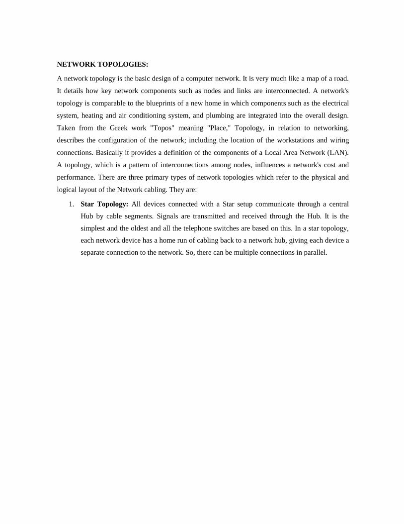
NETWORK TOPOLOGIES: A network topology is the basic design of a computer network. It is very much like a map of a road.
It details how key network components such as nodes and links are interconnected. A network's
topology is comparable to the blueprints of a new home in which components such as the electrical
system, heating and air conditioning system, and plumbing are integrated into the overall design.
Taken from the Greek work "Topos" meaning "Place," Topology, in relation to networking,
describes the configuration of the network; including the location of the workstations and wiring
connections. Basically it provides a definition of the components of a Local Area Network (LAN).
A topology, which is a pattern of interconnections among nodes, influences a network's cost and
performance. There are three primary types of network topologies which refer to the physical and
logical layout of the Network cabling. They are:
1. Star Topology: All devices connected with a Star setup communicate through a central
Hub by cable segments. Signals are transmitted and received through the Hub. It is the
simplest and the oldest and all the telephone switches are based on this. In a star topology,
each network device has a home run of cabling back to a network hub, giving each device a
separate connection to the network. So, there can be multiple connections in parallel.

Advantages o Network administration and error detection is easier because problem is isolated to central node
o Networks runs even if one host fails o Expansion becomes easier and scalability of the network increases
o More suited for larger networks Disadvantages o Broadcasting and multicasting is not easy because some extra functionality needs to be provided
to the central hub o If the central node fails, the whole network goes down; thus making the switch some kind of a
bottleneck o Installation costs are high because each node needs to be connected to the central switch
Bus Topology: The simplest and one of the most common of all topologies, Bus consists of
a single cable, called a Backbone, that connects all workstations on the network using a
single line. All transmissions must pass through each of the connected devices to complete
the desired request. Each workstation has its own individual signal that identifies it and
allows for the requested data to be returned to the correct originator. In the Bus Network,
messages are sent in both directions from a single point and are read by the node (computer
or peripheral on the network) identified by the code with the message. Most Local Area
Networks (LANs) are Bus Networks because the network will continue to function even if
one computer is down. This topology works equally well for either peer to peer or client
server. The purpose of the terminators at either end of the network is to stop the signal
being reflected back.

Advantages o Broadcasting and multicasting is much simpler o Network is redundant in the sense that failure of one node doesn't effect the network. The other
part may still function properly o Least expensive since less amount of cabling is required and no network switches are
required o Good for smaller networks not requiring higher speeds Disadvantages o Trouble shooting and error detection becomes a problem because, logically, all nodes are
equal o Less secure because sniffing is easier o Limited in size and speed
Ring Topology: All the nodes in a Ring Network are connected in a closed circle of cable.
Messages that are transmitted travel around the ring until they reach the computer that they
are addressed to, the signal being refreshed by each node. In a ring topology, the network
signal is passed through each network card of each device and passed on to the next device.
Each device processes and retransmits the signal, so it is capable of supporting many
devices in a somewhat slow but very orderly fashion. There is a very nice feature that
everybody gets a chance to send a packet and it is guaranteed that every node gets to send a
packet in a finite amount of time.

Advantages o Broadcasting and multicasting is simple since you just need to send out one message
o Less expensive since less cable footage is required o It is guaranteed that each host will be able to transmit within a finite time interval o Very orderly network where every device has access to the token and the opportunity to transmit
o Performs better than a star network under heavy network load Disadvantages o Failure of one node brings the whole network down o Error detection and network administration becomes difficult
o Moves, adds and changes of devices can effect the network o
It is slower than star topology under normal load Generally, a BUS architecture is preferred over the other topologies - ofcourse, this is a very
subjective opinion and the final design depends on the requirements of the network more than
anything else. Lately, most networks are shifting towards the STAR topology. Ideally we would
like to design networks, which physically resemble the STAR topology, but behave like BUS or
RING topology.
DEFINE TOKEN RING?
IEEE 802.4: Token Bus Network
In this system, the nodes are physically connected as a bus, but logically form a ring
with tokens passed around to determine the turns for sending. It has the robustness of
the 802.3 broadcast cable and the known worst case behavior of a ring. The structure of
a token bus network is as follows:

A 802.4 frame has the following fields: Preamble: The Preamble is used to synchronize the receiver's clock.
Starting Delimiter (SD) and End Delimiter (ED): The Starting Delimiter and Ending
Delimiter fields are used to mark frame boundaries. Both of them contain analog encoding of
symbols other than 1 or 0 so that they cannot occur accidentally in the user data. Hence no
length field is needed.
Frame Control (FC): This field is used to distinguish data frames from control frames. For
data frames, it carries the frame's priority as well as a bit which the destination can set as an
acknowledgement. For control frames, the Frame Control field is used to specify the frame
type. The allowed types include token passing and various ring maintenance frames.
Destination and Source Address: The Destination and Source address fields may be 2 bytes
(for a local address) or 6 bytes (for a global address).
Data: The Data field carries the actual data and it may be 8182 bytes when 2 byte addresses
are used and 8174 bytes for 6 byte addresses. Checksum: A 4-byte checksum calculated for the data. Used in error detection.
Mechanism:
When the first node on the token bus comes up, it sends a Claim_token packet to
initialize the ring. If more than one station sends this packet at the same time, there is a
collision. Collision is resolved by a contention mechanism, in which the contending
nodes send random data for 1, 2, 3 and 4 units of time depending on the first two bits of
their address. The node sending data for the longest time wins. If two nodes have the
same first two bits in their addresses, then contention is done again based on the next
two bits of their address and so on. After the ring is set up, new nodes which are
powered up may wish to join the ring. For this a node sends Solicit_successor_1
packets from time to time, inviting bids from new nodes to join the ring. This packet
contains the address of the current node and its current successor, and asks for nodes in
between these two addresses to reply. If more than one nodes respond, there will be
collision. The node then sends a Resolve_contention packet, and the contention is
resolved using a similar mechanism as described previously. Thus at a time only one
node gets to enter the ring. The last node in the ring will send a Solicit_successor_2
packet containing the addresses of it and its successor. This packet asks nodes not
having addresses in between these two addresses to respond. A question arises that how
frequently should a node send a Solicit_successor packet? If it is sent too frequently,
then overhead will be too high. Again if it is sent too rarely, nodes will have to wait for
a long time before joining the ring. If the channel is not busy, a node will send a
Solicit_successor packet after a fixed number of token rotations. This number can be
configured by the network administrator. However if there is heavy traffic in the
network, then a node would defer the sending of bids for successors to join in. There
may be problems in the logical ring due to sudden failure of a node. What happens
when a node goes down along with the token? After passing the token, a node, say node
A, listens to the channel to see if its successor either transmits the token or passes a
frame. If neither happens, it resends a token. Still if nothing happens, A sends a
Who_follows packet, containing the address of the down node. The successor of the
down node, say node C, will now respond with a Set_successor packet, containing its
own address. This causes A to set its successor node to C, and the logical ring is
restored. However, if two successive nodes go down suddenly, the ring will be dead and
will have to be built afresh, starting from a Claim_token packet. When a node wants to
shutdown normally, it sends a Set_successor packet to its predecessor, naming its own
successor.
Bit stuffing
The third method allows data frames to contain an arbitrary number of bits and allows
character codes with an arbitrary number of bits per character. At the start and end of
each frame is a flag byte consisting of the special bit pattern 01111110. Whenever the
sender's data link layer encounters five consecutive 1s in the data, it automatically stuffs
a zero bit into the outgoing bit stream. This technique is called bit stuffing. When the

receiver sees five consecutive 1s in the incoming data stream, followed by a zero bit, it
automatically destuffs the 0 bit. The boundary between two frames can be determined
by locating the flag pattern.
\
UNIT-II
DATA LINK LAYER
1. What do you mean by Automatic Repeat Request (ARQ)?
ARQ means retransmission of data in three cases:
Damaged Frame
Lost Frame
Lost Acknowledge
2. What are the responsibilities of Data Link Layer?
The Data Link Layer transforms the physical layer, a raw transmission facility, to a reliable link and is responsible for node-node delivery.
Framing
Physical Addressing
Flow Control
Error Control
Access Control
3. What are the three protocols used for noisy channels?
The three protocols used for noisy channels
Stop – and – Wait ARQ
Go – back – N ARQ
Selective Repeat ARQ
4. What is CSMA/CD?
Carrier Sense Multiple Access with Collision Detection is a protocol used to sense
whether a medium is busy before transmission and it also has the ability to detect whether the packets has collided with another
5. What are the various types of connecting devices?
There are five types of connecting devices
Repeaters
Hubs
Bridges
Routers
Switches.
6. Define Flow control
It refers to a set of procedures used to restrict the amount of data the sender
can sent before waiting for an acknowledgement
7. What are the categories of Flow control?
The categories of Flow control are
Stop& wait
Sliding Window
8. Mention the disadvantages of stop& wait.
Inefficiency
Slow process
9. What are the functions of data link layer?
The functions of data link layer are
Flow control
Error control
10. Define Link Discipline
It coordinates the link system. It determines which device can send and when it can
send.
11. What do you mean by polling?
When the primary device is ready to receive data, it asks the secondary to send data.
This is called polling.
12.What are the various controlled access methods?
The various controlled access methods are
Reservation
Token passing
Polling
13 What are the various Random access methods?\
The various Random access methods are
Slotted ALOHA
CSMA
CSMA/CD,CSMA/CA 14. Define Piconet
A Bluetooth network is called Piconet .It can have up to eight stations one of which

is called the master and the rest are called slaves,
15. What is the frequency range of Bluetooth devices?
The frequency range of Bluetooth device is 2.4 GHZ
16. What is the need of connecting devices?
To connect LANs or segments of LAN we use connecting devices. These devices
can operate in different layers of internet model.
17. What type of address a data link layer is using?
The data link layer is using a physical address
18. What do you mean by Backbone networks?
It allows several LANs to be connected. The architecture used are Star and Bus
19. What is the need of frame relay?
It is a Virtual circuit wide area network that was designed to respond to
demands
for a new type of WAN.
20. What is the maximum length of a datagram?
The maximum length of a datagram is 65,535 bytes.
PART-B
CSMA- Carrier Sense Multiple Acces?s This is the simplest version CSMA protocol as described above. It does not specify any
collision detection or handling. So collisions might and WILL occur and clearly then, this is
not a very good protocol for large, load intensive networks. So, we need an improvement
over CSMA - this led to the development of CSMA/CD. CSMA/CD- CSMA with Collision Detection In this protocol, while transmitting the data, the sender simultaneously tries to receive it.
So, as soon as it detects a collision (it doesn't receive its own data) it stops transmitting.
Thereafter, the node waits for some time interval before attempting to transmit again.
Simply put, "listen while you talk". But, how long should one wait for the carrier to be
freed? There are three schemes to handle this: 10. 1-Persistent: In this scheme, transmission proceeds immediately if the carrier is
idle. However, if the carrier is busy, then sender continues to sense the carrier until it
becomes idle. The main problem here is that, if more than one transmitters are ready to
send, a collision is GUARANTEED!! 11. Non-Persistent: In this scheme, the broadcast channel is not monitored
continuously. The sender polls it at random time intervals and transmits whenever the
carrier is idle. This decreases the probability of collisions. But, it is not efficient in a low
load situation, where numbers of collisions are anyway small. The problems it entails are: o If back-off time is too long, the idle time of carrier is wasted in some sense
o It may result in long access delays 3. p-Persistent: Even if a sender finds the carrier to be idle, it uses a probabilistic
distribution to determine whether to transmit or not. Put simply, "toss a coin to decide". If
the carrier is idle, then transmission takes place with a probability p and the sender waits
with a probability 1-p. This scheme is a good trade off between the Non-persistent and 1-
persistent schemes. So, for low load situations, p is high (example: 1-persistent); and for
high load situations, p may be lower. Clearly, the value of p plays an important role in
determining the performance of this protocol. Also the same p is likely to provide different
performance at different loads. CSMA/CD doesn't work in some wireless scenarios called "hidden node" problems.
Consider a situation, where there are 3 nodes - A, B and C communicating with each other
using a wireless protocol. Morover, B can communicate with both A and C, but A and C lie
outside each other's range and hence can't communicate directly with each other. Now,
suppose both A and C want to communicate with B simultaneously. They both will sense
the carrier to be idle and hence will begin transmission, and even if there is a collision,
neither A nor C will ever detect it. B on the other hand will receive 2 packets at the same
time and might not be able to understand either of them. To get around this problem, a
better version called CSMA/CA was developed.
CSMA with Collision Avoidance
We have observed that CSMA/CD would break down in wireless networks because of
hidden node and exposed nodes problems. We will have a quick recap of these two
problems through examples. Hidden Node Problem In the case of wireless network it is possible that A is sending a message to B, but C is out
of its range and hence while "listening" on the network it will find the network to be free
and might try to send packets to B at the same time as A. So, there will be a collision at B.
The problem can be looked upon as if A and C are hidden from each other. Hence it is
called the "hidden node problem". Exposed Node Problem If C is transmitting a message to D and B wants to transmit a message to A, B will find the
network to be busy as B hears C trnasmitting. Even if B would have transmitted to A, it
would not have been a problem at A or D. CSMA/CD would not allow it to transmit
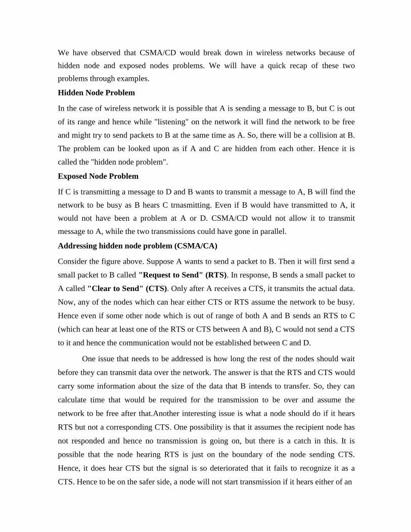
message to A, while the two transmissions could have gone in parallel. Addressing hidden node problem (CSMA/CA) Consider the figure above. Suppose A wants to send a packet to B. Then it will first send a
small packet to B called "Request to Send" (RTS). In response, B sends a small packet to
A called "Clear to Send" (CTS). Only after A receives a CTS, it transmits the actual data.
Now, any of the nodes which can hear either CTS or RTS assume the network to be busy.
Hence even if some other node which is out of range of both A and B sends an RTS to C
(which can hear at least one of the RTS or CTS between A and B), C would not send a CTS
to it and hence the communication would not be established between C and D.
One issue that needs to be addressed is how long the rest of the nodes should wait
before they can transmit data over the network. The answer is that the RTS and CTS would
carry some information about the size of the data that B intends to transfer. So, they can
calculate time that would be required for the transmission to be over and assume the
network to be free after that.Another interesting issue is what a node should do if it hears
RTS but not a corresponding CTS. One possibility is that it assumes the recipient node has
not responded and hence no transmission is going on, but there is a catch in this. It is
possible that the node hearing RTS is just on the boundary of the node sending CTS.
Hence, it does hear CTS but the signal is so deteriorated that it fails to recognize it as a
CTS. Hence to be on the safer side, a node will not start transmission if it hears either of an

RTS or a CTS. The assumption made in this whole discussion is that if a node X can send
packets to a node Y, it can also receive a packet from Y, which is a fair enough assumption
given the fact that we are talking of a local network where standard instruments would be
used. If that is not the case additional complexities would get introduced in the system.
DEFINE ETHERNET?
IEEE 802.3 and Ethernet Very popular LAN standard. Ethernet and IEEE 802.3 are distinct standards but as they are very similar to one another
these words are used interchangeably. A standard for a 1-persistent CSMA/CD LAN. It covers the physical layer and MAC sublayer protocol. Ethernet Physical Layer A Comparison of Various Ethernet and IEEE 802.3 Physical-Layer Specifications Characteristic Ethernet Value IEEE 802.3 Values 10Base5 10Base2 10BaseT Nodes/segment 100 Topology Bus Bus Bus Star 10Base5 means it operates at 10 Mbps, uses baseband signaling and can support segments
of up to 500 meters. The 10Base5 cabling is popularly called the Thick Ethernet. Vampire
taps are used for their connections where a pin is carefully forced halfway into the co-axial
cable's core as shown in the figure below. The 10Base2 or Thin Ethernet bends easily and is
connected using standard BNC connectors to form T junctions (shown in the figure below).
In the 10Base-T scheme a different kind of wiring pattern is followed in which all stations
have a twisted-pair cable running to a central hub (see below). The difference between the

different physical connections is shown below: (a) 10Base5 (b) 10Base2 (c)10Base-T All
802.3 baseband systems use Manchester encoding, which is a way for receivers to
unambiguously determine the start, end or middle of each bit without reference to an
external clock. There is a restriction on the minimum node spacing (segment length
between two nodes) in 10Base5 and 10Base2 and that is 2.5 meter and 0.5 meter
respectively. The reason is that if two nodes are closer than the specified limit then there
will be very high current which may cause trouble in detection of signal at the receiver end.
Connections from station to cable of 10Base5 (i.e. Thick Ethernet) are generally made
using vampire taps and to 10Base2 (i.e. Thin Ethernet) are made using industry standard
BNC connectors to form T junctions. To allow larger networks, multiple segments can be
connected by repeaters as shown. A repeater is a physical layer device. It receives,
amplifies and retransmits signals in either direction. mplifier is not used because amplifier also amplifies the noise in the signal, whereas
repeater regenerates signal after removing the noise. IEEE 802.3 Frame Structure Preamble (7 bytes) Start of Frame Delimiter (1 byte) Dest. Address (2/6 bytes)
Source Address (2/6 bytes) Length (2 bytes) 802.2 Header+Data (46-1500
bytes) Frame Checksum (4 bytes)
A brief description of each of the fields Preamble: Each frame starts with a preamble of 7 bytes, each byte containing the bit
pattern 10101010. Manchester encoding is employed here and this enables the receiver's
clock to synchronize with the sender's and initialise itself. Start of Frame Delimiter: This field containing a byte sequence 10101011 denotes the start of the frame itself. Dest. Address: The standard allows 2-byte and 6-byte addresses. Note that the 2-byte
addresses are always local addresses while the 6-byte ones can be local or global. 2-Byte Address - Manually assigned address Individual(0)/Group(1) (1 bit)
Address of the machine (15 bits) 6-Byte Address - Every Ethernet card with globally unique address
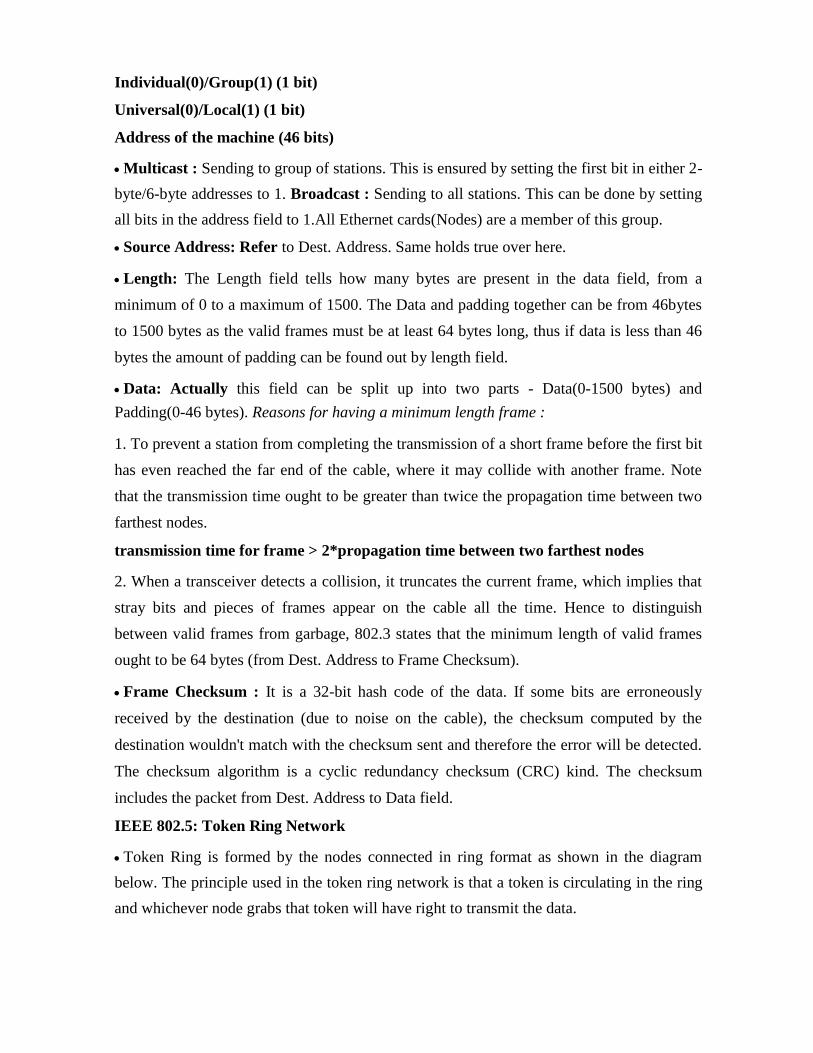
Individual(0)/Group(1) (1 bit) Universal(0)/Local(1) (1 bit) Address of the machine (46 bits) Multicast : Sending to group of stations. This is ensured by setting the first bit in either 2-
byte/6-byte addresses to 1. Broadcast : Sending to all stations. This can be done by setting
all bits in the address field to 1.All Ethernet cards(Nodes) are a member of this group. Source Address: Refer to Dest. Address. Same holds true over here. Length: The Length field tells how many bytes are present in the data field, from a
minimum of 0 to a maximum of 1500. The Data and padding together can be from 46bytes
to 1500 bytes as the valid frames must be at least 64 bytes long, thus if data is less than 46
bytes the amount of padding can be found out by length field. Data: Actually this field can be split up into two parts - Data(0-1500 bytes) and
Padding(0-46 bytes). Reasons for having a minimum length frame : 1. To prevent a station from completing the transmission of a short frame before the first bit
has even reached the far end of the cable, where it may collide with another frame. Note
that the transmission time ought to be greater than twice the propagation time between two
farthest nodes. transmission time for frame > 2*propagation time between two farthest nodes 2. When a transceiver detects a collision, it truncates the current frame, which implies that
stray bits and pieces of frames appear on the cable all the time. Hence to distinguish
between valid frames from garbage, 802.3 states that the minimum length of valid frames
ought to be 64 bytes (from Dest. Address to Frame Checksum). Frame Checksum : It is a 32-bit hash code of the data. If some bits are erroneously
received by the destination (due to noise on the cable), the checksum computed by the
destination wouldn't match with the checksum sent and therefore the error will be detected.
The checksum algorithm is a cyclic redundancy checksum (CRC) kind. The checksum
includes the packet from Dest. Address to Data field. IEEE 802.5: Token Ring Network Token Ring is formed by the nodes connected in ring format as shown in the diagram
below. The principle used in the token ring network is that a token is circulating in the ring
and whichever node grabs that token will have right to transmit the data.

Whenever a station wants to transmit a frame it inverts a single bit of the 3-byte token which
instantaneously changes it into a normal data packet. Because there is only one token, there
can at most be one transmission at a time. Since the token rotates in the ring it is guaranteed that every node gets the token with in
some specified time. So there is an upper bound on the time of waiting to grab the token so
that starvation is avoided. There is also an upper limit of 250 on the number of nodes in the network. To distinguish the normal data packets from token (control packet) a special sequence is
assigned to the token packet. When any node gets the token it first sends the data it wants to
send, then recirculates the token. If a node transmits the token and nobody wants to send the
data the token comes back to the sender. If the first bit of the token reaches the sender before
the transmission of the last bit, then error situation arises. So to avoid this we should have:
Propogation delay + transmission of n-bits (1-bit delay in each node ) > transmission of the token time A station may hold the token for the token-holding time
which is 10 ms unless the installation sets a different value. If there is enough time left after
the first frame has been transmitted to send more frames, then these frames may be sent as
well. After all pending frames have been transmitted or the transmission frame would exceed
the token-holding time, the station regenerates the 3-byte token frame and puts it back on the
ring. Modes of Operation
1. Listen Mode: In this mode the node listens to the data and transmits the data to the
next node. In this mode there is a one-bit delay associated with the transmission
2. Transmit Mode: In this mode the node just discards the any data and puts the data onto
the network.
3. By-pass Mode: In this mode reached when the node is down. Any data is just bypassed.
There is no one-bit delay in this mode.
EXPLAIN FLOW CONTROL AND ERROR CONTROL?
Flow Control Consider a situation in which the sender transmits frames faster than the receiver can accept
them. If the sender keeps pumping out frames at high rate, at some point the receiver will be
completely swamped and will start losing some frames. This problem may be solved by
introducing flow control. Most flow control protocols contain a feedback mechanism to
inform the sender when it should transmit the next frame. Mechanisms for Flow Control: Stop and Wait Protocol: This is the simplest file control protocol in which the sender
transmits a frame and then waits for an acknowledgement, either positive or negative, from
the receiver before proceeding. If a positive acknowledgement is received, the sender
transmits the next packet; else it retransmits the same frame. However, this protocol has one
major flaw in it. If a packet or an acknowledgement is completely destroyed in transit due to a
noise burst, a deadlock will occur because the sender cannot proceed until it receives an
acknowledgement. This problem may be solved using timers on the sender's side. When the
frame is transmitted, the timer is set. If there is no response from the receiver within a certain
time interval, the timer goes off and the frame may be retransmitted. Sliding Window Protocols: In spite of the use of timers, the stop and wait protocol still
suffers from a few drawbacks. Firstly, if the receiver had the capacity to accept more than one
frame, its resources are being underutilized. Secondly, if the receiver was busy and did not
wish to receive any more packets, it may delay the acknowledgement. However, the timer on
the sender's side may go off and cause an unnecessary retransmission. These drawbacks are
overcome by the sliding window protocols. In sliding window protocols the sender's data link
layer maintains a 'sending window' which consists of a set of sequence numbers
corresponding to the frames it is permitted to send. Similarly, the receiver maintains a
'receiving window' corresponding to the set of frames it is permitted to accept. The window
size is dependent on the retransmission policy and it may differ in values for the receiver's
and the sender's window. The sequence numbers within the sender's window represent the
frames sent but as yet not acknowledged. Whenever a new packet arrives from the network layer, the upper edge of the window is advanced by one. When an acknowledgement arrives from the receiver the lower edge is advanced by one. The receiver's
window corresponds to the frames that the receiver's data link layer may accept. When a
frame with sequence number equal to the lower edge of the window is received, it is passed to
the network layer, an acknowledgement is generated and the window is rotated by one. If
however, a frame falling outside the window is received, the receiver's data link layer has two
options. It may either discard this frame and all subsequent frames until the desired frame is
received or it may accept these frames and buffer them until the appropriate frame is received
and then pass the frames to the network layer in sequence.
In this simple example, there is a 4-byte sliding window. Moving from left to right,
the window "slides" as bytes in the stream are sent and acknowledged. Most sliding
window protocols also employ ARQ ( Automatic Repeat reQuest ) mechanism. In
ARQ, the sender waits for a positive acknowledgement before proceeding to the next
frame. If no acknowledgement is received within a certain time interval it retransmits
the frame. ARQ is of two types:
Go Back 'n': If a frame is lost or received in error, the receiver may simply discard all
subsequent frames, sending no acknowledgments for the discarded frames. In this case the
receive window is of size 1. Since no acknowledgements are being received the sender's
window will fill up, the sender will eventually time out and retransmit all the
unacknowledged frames in order starting from the damaged or lost frame. The maximum
window size for this protocol can be obtained as follows. Assume that the window size of the
sender is n. So the window will initially contain the frames with sequence numbers from 0 to
(w-1). Consider that the sender transmits all these frames and the receiver's data link layer
receives all of them correctly. However, the sender's data link layer does not receive any
acknowledgements as all of them are lost. So the sender will retransmit all the frames after its
timer goes off. However the receiver window has already advanced to w. Hence to avoid
overlap , the sum of the two windows should be less than the sequence number space. w-1 + 1 < Sequence Number Space i.e., w < Sequence Number Space Maximum Window Size = Sequence Number Space - 1 2. Selective Repeat: In this protocol rather than discard all the subsequent frames following a
damaged or lost frame, the receiver's data link layer simply stores them in
buffers. When the sender does not receive an acknowledgement for the first frame it's timer
goes off after a certain time interval and it retransmits only the lost frame. Assuming error -
free transmission this time, the sender's data link layer will have a sequence of a many correct
frames which it can hand over to the network layer. Thus there is less overhead in
retransmission than in the case of Go Back n protocol. In case of selective repeat protocol the
window size may be calculated as follows. Assume that the size of both the sender's and the
receiver's window is w. So initially both of them contain the values 0 to (w-1). Consider that
sender's data link layer transmits all the w frames; the receiver's data link layer receives them

correctly and sends acknowledgements for each of them. However, all the acknowledgemnets
are lost and the sender does not advance it's window. The receiver window at this point
contains the values w to (2w-1). To avoid overlap when the sender's data link layer
retransmits, we must have the sum of these two windows less than sequence number space.
Hence, we get the condition
Maximum Window Size = Sequence Number Space / 2
UNIT-III
NETWORK LAYER
1. What are the responsibilities of Network Layer?
The Network Layer is responsible for the source-to-destination delivery of packet
possibly across multiple networks (links).
a. Logical Addressing
b. Routing.
2. What is DHCP?
The Dynamic Host Configuration Protocol has been derived to provide dynamic
configuration. DHCP is also needed when a host moves from network to network or is
connected and disconnected from a network.
3. Define ICMP?
Internet Control Message Protocol is a collection of error messages that are sent back
to the source host whenever a router or host is unable to process an IP datagram successfully.
4. What is BOOTP?
BOOTSTRAP Protocol is a client/server protocol designed to provide the following
four information for a diskless computer or a computer that is booted for the first time. IP address, Subnet mask, IP address of a router, IP address of a name server.

5. What is the need of internetwork?
To exchange data between networks, they need to be connected to make an
Internetwork.
6. What are the types of class full addressing?
The types are Class A, Class B, Class C, Class D, Class E 7. What do you mean by ARP?
ARP stands for Address resolution protocol, maps an IP address to a MAC address 8. What do you mean by RARP?
RARP stands for Reverse Address resolution protocol, maps an MAC address to a
IP address
9. Define Delivery of a packet.
t refers to the way a packet is handled by the underlying network under the control of network layer 12. What are the types of delivery?
There are two types of delivery
1. Direct delivery 2. Indirect delivery
13. What is class less addressing?
Classless addressing requires hierarchical and geographical routing to prevent
immense routing tables
12. What is Unicast & Multicast communication?
Unicast communication is one source sending a packet to one destination.
Multicast communication is one source sending a packet to multiple destinations. 13. What do you mean by Net id & Host id?
The Internet address (or IP address) is 32 bits (for IPv4) that uniquely and universally
defines a host or router on the Internet. The portion of the IP address that identifies the
network is called the net id. The portion of the IP address that identifies the host or router on the network is called the host id.
14. Define forwarding.
It refers to a way a packet is delivered to next station. It requires a host or a Router to
have a routing table
15. What are the common notations used for address? The two common notations used for address are
Binary notations
Dotted decimal notations
16. What are the advantages of IPV6 over IPV4?
Larger address space Better header format New options Support for more security
17. Define static mapping.
It creating a table that associates an IP address with a MAC address 18. Compare direct delivery & indirect delivery
In direct delivery source and destination node belong to e same network
In indirect delivery source and destination node belong to different network 19. What are the rules of non boundary-level masking?
• The bytes in the IP address that corresponds to 255 in the mask will be repeated
in the Sub network address
• The bytes in the IP address that corresponds to 0 in the mask will change to 0 in the sub network address
• For other bytes, use the bit-wise AND operator 20. What is Fragmentation?
Fragmentation is the division of a datagram into smaller units to accommodate the
MTU of a data link protocol.
PART-B
What is Network Layer? The network layer is concerned with getting packets from the source all the way to the
destination. The packets may require to make many hops at the intermediate routers while
reaching the destination. This is the lowest layer that deals with end to end transmission. In
order to achieve its goals, the network layer must know about the topology of the
communication network. It must also take care to choose routes to avoid overloading of some
of the communication lines while leaving others idle. The network layer-transport layer
interface frequently is the interface between the carrier and the customer, that is the boundary
of the subnet. The functions of this layer include : 1. Routing - The process of transferring packets received from the Data Link Layer of the
source network to the Data Link Layer of the correct destination network is called routing.
Involves decision making at each intermediate node on where to send the packet next so that
it eventually reaches its destination. The node which makes this choice is called a router. For
routing we require some mode of addressing which is recognized by the Network Layer. This
addressing is different from the MAC layer addressing.
2. Inter-networking - The network layer is the same across all physical networks (such as
Token-Ring and Ethernet). Thus, if two physically different networks have to
communicate, the packets that arrive at the Data Link Layer of the node which connects
these two physically different networks, would be stripped of their headers and passed to
the Network Layer. The network layer would then pass this data to the Data Link Layer
of the other physical network. 3. Congestion Control - If the incoming rate of the packets arriving at any router is more than
the outgoing rate, then congestion is said to occur. Congestion may be caused by many
factors. If suddenly, packets begin arriving on many input lines and all need the same output
line, then a queue will build up. If there is insufficient memory to hold all of them, packets
will be lost. But even if routers have an infinite amount of memory, congestion gets worse,
because by the time packets reach to the front of the queue, they have already timed out
(repeatedly), and duplicates have been sent. All these packets are dutifully forwarded to the

next router, increasing the load all the way to the destination. Another reason for congestion
are slow processors. If the router's CPUs are slow at performing the bookkeeping
tasks required of them, queues can build up, even though there is excess line capacity. Similarly, low-bandwidth lines can also cause congestion. Addressing Scheme IP addresses are of 4 bytes and consist of : i) The network address,
followed by ii) The host address The first part identifies a network on which the host resides
and the second part identifies the particular host on the given network. Some nodes which
have more than one interface to a network must be assigned separate internet addresses for
each interface. This multi-layer addressing makes it easier to find and deliver data to the
destination. A fixed size for each of these would lead to wastage or under-usage that is either
there will be too many network addresses and few hosts in each (which causes problems for
routers who route based on the network address) or there will be very few network addresses
and lots of hosts (which will be a waste for small network requirements). Thus, we do away
with any notion of fixed sizes for the network and host addresses. We classify networks as
follows: 1. Large Networks: 8-bit network address and 24-bit host address. There are approximately
16 million hosts per network and a maximum of 126 ( 2^7 - 2 ) Class A networks can be
defined. The calculation requires that 2 be subtracted because 0.0.0.0 is reserved for use as
the default route and 127.0.0.0 be reserved for the loop back function. Moreover each Class A
network can support a maximum of 16,777,214 (2^24 - 2) hosts per network. The host
calculation requires that 2 be subtracted because all 0's are reserved to identify the network
itself and all 1s are reserved for broadcast addresses. The reserved numbers may not be
assigned to individual hosts. 2. Medium Networks: 16-bit network address and 16-bit host address. There are
approximately 65000 hosts per network and a maximum of 16,384 (2^14) Class B networks
can be defined with up to (2^16-2) hosts per network. 3. Small Networks: 24-bit network address and 8-bit host address. There are approximately
250 hosts per network. You might think that Large and Medium networks are sort of a waste as few corporations or
organizations are large enough to have 65000 different hosts. (By the way, there are very few

corporations in the world with even close to 65000 employees, and even in these it is highly unlikely that each employee has his/her own computer connected to the network.)
Well, if you think so, you're right. This decision seems to have been a mistake.
EXPLAIN SUBNETTING?
Subnetting: Sub netting means organizing hierarchies within the network by dividing the
host ID as per our network. For example consider the network ID: 150.29.x.y We could
organize the remaining 16 bits in any way, like : 4 bits - department 4 bits - LAN 8 bits – host
This gives some structure to the host IDs. This division is not visible to the outside world.
They still see just the network number, and host number (as a whole). The network will have
an internal routing table which stores information about which router to send an address to.
Now consider the case where we have : 8 bits - subnet number, and 8 bits - host number.
Each router on the network must know about all subnet numbers. This is called the subnet
mask. We put the network number and subnet number bits as 1 and the host bits as 0.
Therefore, in this example the subnet mask becomes : 255.255.255.0 . The hosts also need to
know the subnet mask when they send a packet. To find if two addresses are on the same
subnet, we can AND source address with subnet mask, and destination address with with
subnet mask, and see if the two results are the same. The basic reason for sub netting was
avoiding broadcast. But if at the lower level, our switches are smart enough to send directed
messages, then we do not need sub netting. However, sub netting has some security related
advantages. Supernetting This is moving towards class-less addressing. We could say that the network
number is 21 bits ( for 8 class C networks ) or say that it is 24 bits and 7 numbers following
that. For example : a.b.c.d / 21 This means only look at the first 21 bits as the network
address. Addressing on IITK Network If we do not have connection with the outside world directly then we could have Private IP
addresses ( 172.31 ) which are not to be publicised and routed to the outside world. Switches
will make sure that they do not broadcast packets with such addressed to the outside world.
The basic reason for implementing subnetting was to avoid broadcast. So in our case we can
have some subnets for security and other reasons although if the switches could do the
routing properly, then we do not need subnets. In the IITK network we have three subnets -
CC, CSE building are two subnets and the rest of the campus is one subset.

DEFINE HLEN PACKET STRUCTURE?
Header Length: We could have multiple sized headers so we need this field. Header will always
be a multiple of 4bytes and so we can have a maximum length of the field as 15, so the maximum
size of the header is 60 bytes ( 20 bytes are mandatory ).
2. Type Of Service (ToS) : This helps the router in taking the right routing decisions. The
structure is : First three bits : They specify the precedences i.e. the priority of the packets. Next three bits : o D bit - D stands for delay. If the D bit is set to 1, then this means that the application is delay
sensitive, so we should try to route the packet with minimum delay. o T bit - T stands for throughput. This tells us that this particular operation is throughput
sensitive. o R bit - R stands for reliability. This tells us that we should route this packet through a more
reliable network. Last two bits: The last two bits are never used. Unfortunately, no router in this world looks at
these bits and so no application sets them nowadays. The second word is meant for handling
fragmentations. If a link cannot transmit large packets, then we fragment the packet and put
sufficient information in the header for recollection at the destination. 3. ID Field : The source and ID field together will represent the fragments of a unique packet. So
each fragment will have a different ID.
4. Offset : It is a 13 bit field that represents where in the packet, the current fragment starts. Each
bit represents 8 bytes of the packet. So the packet size can be at most 64 kB. Every fragment
except the last one must have its size in bytes as a multiple of 8 in
Header Length: We could have multiple sized headers so we need this field. Header will always
be a multiple of 4bytes and so we can have a maximum length of the field as 15, so the maximum
size of the header is 60 bytes ( 20 bytes are mandatory ).
2. Type Of Service (ToS) : This helps the router in taking the right routing decisions. The
structure is : First three bits : They specify the precedences i.e. the priority of the packets.
Next three bits : o D bit - D stands for delay. If the D bit is set to 1, then this means that the application is delay
sensitive, so we should try to route the packet with minimum delay.
o T bit - T stands for throughput. This tells us that this particular operation is throughput
sensitive.
o R bit - R stands for reliability. This tells us that we should route this packet through a more
reliable network. Last two bits: The last two bits are never used. Unfortunately, no router in this world looks at these bits and so no application sets them nowadays. The second word is meant for handling fragmentations. If a link cannot transmit large packets, then we fragment the packet and put sufficient information in the header for recollection at the destination. 3. ID Field : The source and ID field together will represent the fragments of a unique packet. So
each fragment will have a different ID.
4. Offset : It is a 13 bit field that represents where in the packet, the current fragment starts. Each
bit represents 8 bytes of the packet. So the packet size can be at most 64 kB. Every fragment
except the last one must have its size in bytes as a multiple of 8 in order to ensure compliance
with this structure. The reason why the position of a fragment is given as an offset value
instead of simply numbering each packet is because refragmentation may occur somewhere
on the path to the other node. Fragmentation, though supported by IPv4 is not encouraged.
This is because if even one fragment is lost the entire packet needs to be discarded. A
quantity M.T.U (Maximum Transmission Unit) is defined for each link in the route. It is the
size of the largest packet that can be handled by the link. The Path-M.T.U is then defined as
the size of the largest packet that can be handled by the path. It is the smallest of all the
MTUs along the path. Given information about the path MTU we can send packets with sizes
smaller than the path MTU and thus prevent fragmentation. This will not completely prevent
it because routing tables may change leading to a change in the path. 5. Flags :It has three bits - o M bit : If M is one, then there are more fragments on the way and if M is 0, then it is the
last fragment o DF bit : If this bit is sent to 1, then we should not fragment such a packet.
o Reserved bit : This bit is not used.
Reassembly can be done only at the destination and not at any intermediate node. This is
because we are considering Datagram Service and so it is not guaranteed that all the
fragments of the packet will be sent thorough the node at which we wish to do reassembly. 6. Total Length: It includes the IP header and everything that comes after it. 7. Time To Live (TTL) : Using this field, we can set the time within which the packet
should be delivered or else destroyed. It is strictly treated as the number of hops. The packet
should reach the destination in this number of hops. Every router decreases the value as the
packet goes through it and if this value becomes zero at a particular router, it can be
destroyed.
8. Protocol : This specifies the module to which we should hand over the packet ( UDP or
TCP ). It is the next encapsulated protocol. Value Protocol 0 Pv6 Hop-by-Hop Option. 2. ICMP, Internet Control Message Protocol. 3. IGMP, Internet Group Management Protocol. RGMP, Router-port Group Management
Protocol. 4. GGP, Gateway to Gateway Protocol. 5. IP in IP encapsulation. 6. ST, Internet Stream Protocol. 7. TCP, Transmission Control Protocol. 8. UCL, CBT. 9. EGP, Exterior Gateway Protocol. 10. IGRP. 11. BBN RCC Monitoring 12. NVP, Network Voice Protocol. 13. PUP. 14. ARGUS. 14 EMCON, Emission Control Protocol. 15 XNET, Cross Net Debugger. 16 Chaos. 17 UDP, User Datagram Protocol. 18 TMux, Transport Multiplexing Protocol. 19 DCN Measurement Subsystems. - - 255

9. Header Checksum : This is the usual checksum field used to detect errors. Since the TTL
field is changing at every router so the header checksum ( upto the options field ) is checked and recalculated at every router. 10. Source : It is the IP address of the source node 11. Destination : It is the IP address of the destination node. 12. IP Options : The options field was created in order to allow features to be added into IP as
time passes and requirements change. Currently 5 options are specified although not all routers
support them. They are: o Securtiy: It tells us how secret the information is. In theory a military router might use this
field to specify not to route through certain routers. In practice no routers support this field.
www.roeverengg.edu.in
o Source Routing: o It is used when we want the source to dictate how the packet traverses the network. It is of 2
types. -> Loose Source Record Routing (LSRR): It requires that the packet traverse a list of
specified routers, in the order specified but the packet may pass though some other routers as
well. -> Strict Source Record Routing (SSRR): It requires that the packet traverse only the set
of specified routers and nothing else. If it is not possible, the packet is dropped with an error
message sent to the host.

In this the intermediate routers put there IP addresses in the header, so that the destination knows
the entire path of the packet. Space for storing the IP address is specified by the source itself. The
pointer field points to the position where the next IP address has to be written. Length field gives
the number of bytes reserved by the source for writing the IP addresses. If the space provided for
storing the IP addresses of the routers visited, falls short while storing these addresses, then the
subsequent routers do not write their IP addresses

UNIT-IV
TRANSPORT LAYER
1. What are the responsibilities of Transport Layer?
The Transport Layer is responsible for source-to-destination delivery of the entire
message.
a. Service-point Addressing
b. Segmentation and reassembly
c. Connection Control
d. Flow Control
e. Error Control
15. Define Congestion
It will occur if the number of packets sent to the network is greater than the Capacity
of the network. 3. What do you mean by Congestion control?
It is a mechanism and technique to control the congestion 4. What are the types of congestion control?
There are two types of congestion control
Open loop congestion control Closed loop congestion control
5. What are the two factors that measure network performance?
The two factors that measure network performance are
Delay
Throughput
6. Compare Open loop Congestion Control & Closed loop congestion control
In Open loop congestion control, policies are applied to prevent congestion before it
happens.
In Closed loop congestion control, policies are applied to reduce congestion after it
happens.

7. What is meant by quality of service?
The quality of service defines a set of attributes related to the performance of the is
connection. For each connection, the user can request a particular attribute each service
class associated with a set of attributes.
8. What do you mean by TCP?
TCP guarantees the reliable, in order delivery of a stream of bytes. It is a full-duplex
protocol, meaning that each TCP connection supports a pair of byte streams, one flowing
in each direction.
9. Explain the three types of addresses in TCP/IP?
Three types of addresses are used by systems using the TCP/IP protocol: the
physical address, the internetwork address (IP address), and the port address
10. What are the flow characteristics related to QOS?
The flow characteristics related to QOS are
`Reliability
Delay
Jitter
Bandwidth
11. What are the techniques to improve QOS?
The techniques to improve QOS are
Scheduling Traffic shaping Resource reservation Admission control
12. Define Socket address
The combination of IP address and port address is called Socket address 13. What are the two types of protocols used in Transport layer?
The two types of protocols used in Transport layer are
TCP UDP
14.Define Throughput.
It is defines as a number of packets passing through the network in a unit of time
15.Define UDP
User datagram protocol is a Unreliable, connectionless protocol, used along with the
IP protocol 16.What is the need of port numbers?
Port numbers are used as a addressing mechanism in transport layer 17. What are the types of port numbers used in transport layer?
Well-known port Registered port Dynamic port
18. Why TCP services are called Stream delivery services?
TCP allows the sending process to deliver data as a stream of bytes and the receiving
process to deliver data as a stream of bytes. so it is called as stream of bytes. 19 .Define jitter
It is the variation in delay for packets belonging to same flow . 20. Compare connectionless service & connection oriented service
In connection less service there is no connection between transmitter & receiver
Ex: TCP
In connection oriented service there is a connection between transmitter & receiver
Ex: UDP

PART-B
DEFINE TIMESTAMP ROUTING? It is similar to record route option except that nodes also add their timestamps to the packet.
The new fields in this option are -> Flags: It can have the following values
0- Enter only timestamp.
1- The nodes should enter Timestamp as well as their IP.
3 - The source specifies the IPs that should enter their timestamp. A special point of
interest is that only if the IP is the same as that at the pointer then the time is entered. Thus
if the source specifies IP1 and IP2 but IP2 is first in the path then the field IP2 is left empty,
even after having reached IP2 but before reaching IP1. -> Overflow: It stores the number of nodes that were unable to add their timestamps to the
packet. The maximum value is 15.
FORMAT: Copy bit: It says whether the option is to be copied to every fragment or not. a value of 1
stands for copying and 0 stands for not copying.
Type: It is a 2 bit field. Currently specified values are 0 and 2. 0 means the option is a control option while 2 means the option is for measurement
Option Number: It is a 5 bit field which specifies the option number. For all options a length field is put in order that a router not familiar with the option will know
how many bytes to skip. Thus every option is of the form o TLV: Type/Length/Value. This format is followed in not only in IP but in nearly all major protocols.
Routing
Routing is the process of forwarding of a packet in a network so that it reaches its intended destination. The main goals of routing are: 1. Correctness: The routing should be done properly and correctly so that the packets may
reach their proper destination. 2. Simplicity: The routing should be done in a simple manner so that the overhead is as low
as possible. With increasing complexity of the routing algorithms the overhead also
increases. 3. Robustness: Once a major network becomes operative, it may be expected to run
continuously for years without any failures. The algorithms designed for routing should be
robust enough to handle hardware and software failures and should be able to cope with
changes in the topology and traffic without requiring all jobs in all hosts to be aborted and
the network rebooted every time some router goes down. 4. Stability: The routing algorithms should be stable under all possible circumstances. 5. Fairness: Every node connected to the network should get a fair chance of transmitting
their packets. This is generally done on a first come first serve basis. 6. Optimality: The routing algorithms should be optimal in terms of throughput and
minimizing mean packet delays. Here there is a trade-off and one has to choose depending
on his suitability. Classification of Routing Algorithms The routing algorithms may be classified as follows: 1. Adaptive Routing Algorithm: These algorithms change their routing decisions to
reflect changes in the topology and in traffic as well. These get their routing information
from adjacent routers or from all routers. The optimization parameters are the distance,
number of hops and estimated transit time. This can be further classified as follows: 1. Centralized: In this type some central node in the network gets entire information about
the network topology, about the traffic and about other nodes. This then transmits this
information to the respective routers. The advantage of this is that only one node is required
to keep the information. The disadvantage is that if the central node goes down the entire
network is down, i.e. single point of failure. 2. Isolated: In this method the node decides the routing without seeking information from
other nodes. The sending node does not know about the status of a particular link. The

disadvantage is that the packet may be send through a congested route resulting in a delay.
Some examples of this type of algorithm for routing are:
Hot Potato: When a packet comes to a node, it tries to get rid of it as fast as it can, by
putting it on the shortest output queue without regard to where that link leads. A variation
of this algorithm is to combine static routing with the hot potato algorithm. When a packet
arrives, the routing algorithm takes into account both the static weights of the links and the
queue lengths.
Backward Learning: In this method the routing tables at each node gets modified by
information from the incoming packets. One way to implement backward learning is to
include the identity of incremented on each hop. When a node receives a packet in a particular
line, it notes down the number of hops it has taken to reach it from the source node. If the
previous value of hop count stored in the node is better than the current one then nothing is done but if the current value is better then the value is updated for
future use. The problem with this is that when the best route goes down then it cannot recall the
second best route to a particular node. Hence all the nodes have to forget the stored
informations periodically and start all over again. 3. Distributed: In this the node receives information from its neighbouring nodes and then
takes the decision about which way to send the packet. The disadvantage is that if in between
the the interval it receives information and sends the paket something changes then the packet
may be delayed.
Define Dijkstra's Algorithm? Notation: Di = Length of shortest path from node 'i' to node 1. di,j = Length of path
between nodes i and j . Algorithm Each node j is labeled with Dj, which is an estimate of cost of path from node j
to node 1. Initially, let the estimates be infinity, indicating that nothing is known about the

paths. We now iterate on the length of paths, each time revising our estimate to lower
values, as we obtain them. Actually, we divide the nodes into two groups ; the first one,
called set P contains the nodes whose shortest distances have been found, and the other Q
containing all the remaining nodes. Initially P contains only the node 1. At each step, we
select the node that has minimum cost path to node 1. This node is transferred to set P. At
the first step, this corresponds to shifting the node closest to 1 in P. Its minimum cost to
node 1 is now known. At the next step, select the next closest node from set Q and update
the labels corresponding to each node using : Dj = min [ Dj , Di + dj,i ] Finally, after N-1
iterations, the shortest paths for all nodes are known, and the algorithm terminates. Principle Let the closest node to 1 at some step be i. Then i is shifted to P. Now, for each
node j , the closest path to 1 either passes through i or it doesn't. In the first case Dj remains
the same. In the second case, the revised estimate of Dj is the sum Di + di,j . So we take the
minimum of these two cases and update Dj accordingly. As each of the nodes get
transferred to set P, the estimates get closer to the lowest possible value. When a node is
transferred, its shortest path length is known. So finally all the nodes are in P and the Dj 's
represent the minimum costs. The algorithm is guaranteed to terminate in N-1 iterations and
its complexity is O( N2 )
.Define Floyd Warshall Algorithm?
This algorithm iterates on the set of nodes that can be used as intermediate nodes on paths.
This set grows from a single node ( say node 1 ) at start to finally all the nodes of the graph.
At each iteration, we find the shortest path using given set of nodes as intermediate nodes,
so that finally all the shortest paths are obtained. Notation Di,j [n] = Length of shortest path
between the nodes i and j using only the nodes 1,2,....n as intermediate nodes. Initial
Condition Di,j[0] = di,j for all nodes i,j . Algorithm Initially, n = 0. At each iteration, add next node to n. i.e. For n = 1,2, .....N-1 ,
Di,j[n + 1] = min { Di,j[n] , Di,n+1[n] + Dn+1,j[n] } Principle Suppose the shortest path
between i and j using nodes 1,2,...n is known. Now, if node n+1 is allowed to be an
intermediate node, then the shortest path under new conditions either passes through node
n+1 or it doesn't. If it does not pass through the node n+1, then Di,j[n+1] is same as Di,j[n] .
Else, we find the cost of the new route, which is obtained from the sum, Di,n+1[n] +
Dn+1,j[n]. So we take the minimum of these two cases at each step. After adding all the
nodes to the set of intermediate nodes, we obtain the shortest paths between all pairs of

nodes together. The complexity of Floyd-Warshall algorithm is O ( N3 ). It is observed that
all the three algorithms mentioned above give comparable performance, depending upon
the exact topology of the network
Explain DHCP (Dynamic Host Configuration Protocol)? DHCP (Dynamic Host Configuration Protocol) is a protocol that lets network
administrators manage centrally and automate the assignment of Internet Protocol (IP)
addresses in an organization's network. If a machine uses Internet's set of protocol
(TCP/IP), each machine that can connect to the Internet needs a unique IP address. When
an organization sets up its computer users with a connection to the Internet, an IP address
must be assigned to each machine. Without DHCP, the IP address must be entered
manually at each computer and, if computers move to another location in another part of
the network, a new IP address must be entered. DHCP lets a network administrator
supervise and distribute IP addresses from a central point and automatically sends a new IP
address when a computer is plugged into a different place in the network. IP Address Allocation Mechanism DHCP supports three mechanisms for IP address allocation. Automatic allocation: DHCP assigns a permanent IP address to a host. Dynamic allocation: DHCP assigns an IP address to a host for a limited period of time
(or until the host explicitly relinquishes the address). Manual allocation: Host's IP address is assigned by the network administrator, and
DHCP is used simply to convey the assigned address to the host. A particular network will
use one or more of these mechanisms, depending on the policies of the network
administrator. Messages Used by DHCP DHCP Discover - Client broadcast to locate available servers. It is assumed at least one
of the servers will have resources to fulfil the request.( may include additional pointers to
specific services required eg. particular subnet, minimum time limit etc ). DHCP Offer - Server to client in response to DHCP Discover with offer of configuration parameters.

DHCP Request - Client broadcast to servers requesting offered parameters from one
server and implicitly declining offers from all others.( also important in case of lease
renewal if the alloted time is about to expire ). DHCP Decline - Client to server indicating configuration parameters invalid. DHCP Release - Client to server relinquishing network address and cancelling current
lease.( in case of a graceful shut down DHCP server is sent a DHCP Release by the host
machine). DHCP Ack - Server to client with configuration parameters, including committed Network address. DHCP Nack - Server to client refusing request for configratin parameters (eg. requested
network address already allocated). Timers Used Note that lease time is the time specified by the server for which the services have been
provided to the client. Lease Renewal Timer - When this timer expires machine will ask the server for more time sending a DHCP Request. Lease Rebinding Timer - Whenever this timer expires, we have not been receiving any
response from the server and so we can assume the server is down. Thus send a DHCP
Request to all the servers using IP Broadcast facility. This is only point of difference
between Lease renewal and rebinding. Lease Expiry Timer - Whenever this timer expires, the system will have to start crashing
as the host does not have a valid IP address in the network. Timer Configuration Policy The timers have this usual setting which can be configured depending upon the usage
pattern of the network. An example setting has been discussed below. Lease Renewal = 50
% Lease time Lease Rebinding = 87.5 % Lease time Lease Expiry = 100 % Lease time

UNIT-V
APPLICATION LAYER
1. What are the responsibilities of Application Layer?
The Application Layer enables the user, whether human or software, to access the
network. It provides user interfaces and support for services such as e-mail, shared database
management and other types of distributed information services
o Network virtual Terminal
o File transfer, access and Management (FTAM) o Mail services o Directory Services
2. What is Encapsulation and De-capsulation ?
To send a message from one application program to another, the TCP/UDP
protocol encapsulates and de-capsulate messages. 3. What is DNS?
Domain name service is the method by which Internet address in mnemonic form
such assun.it.ac.in are converted into the equivalent numeric IP address such as 134.220.4.1
4. What is Fully Qualified Domain Name?
If a label is terminated by a null string is called a Fully Qualified Domain Name,
5. What is Generic Domains?
Generic domain define registered hosts according to their generic behaviour. Each
node in the tree defines a domain, which is an index to the domain name space database
Eg. com – Commercial organizations
edu - Educational institutions
gov - Government institutions
6. What is simple mail transfer protocol?
The TCP/IP protocol that supports electronic mail on the internet is called Simple
Mail Transfer Protocol (SMTP). It is a system for sending messages to other computer users
based on email addresses.
7. What is User Agent?
A user Agent is defined in SMTP, but the implementation details are not. The UA
is normally a program used to send and receive mail
8. What do you mean by File transfer protocol?
It is a standard mechanism provided by the internet for copying a file from one
host to another
9. What are the two types of connections in FTP?
The two types of connections in FTP are
Control connection
Open connection 10. Define HTTP.
It is used mainly to access data on the World Wide Web. The protocol transfer data
in the form of plaintext, hypertext, audio, video and so on
11. What are the types of messages in HTTP transaction?
The types of messages in HTTP transaction are
Request messages
Response messages
12. What are the parts of a browser?
The parts of a browser are
A controller
A client program
Interpreter 13. Name the four aspects of security.
Privacy Authentication
Integrity
Non-repudiation
14. Define Cryptography.
The science and art of manipulating messages to make them secure.
15, Define authentication.
It means that the receiver is sure of the sender identity. 16. What do you mean by encryption?
The process of converting plain text to cipher text.

17. Define Privacy
It means that sender and receiver expect confidentiality. 18. What do you mean by Symmetric key cryptography?
In Symmetric key cryptography both the parties will use the same key. 19. What are steps to transfer a mail message?
The steps in transferring a mail message are
a) Connection establishment
b) Mail transfer
c) Connection termination
20. What is POP?
Post Office Protocol, version3 (POP3) and Internet Mail Access Protocol version4
(IMAP4) are protocol used by a mail server in conjunction with SMTP to receive and hold
mail for hosts.
PART-B
DNS (Domain Name Service) The internet primarily uses IP addresses for locating nodes. However, its humanly not possible
for us to keep track of the many important nodes as numbers. Alphabetical names as we see
would be more convenient to remember than the numbers as we are more familiar with words.
Hence, in the chaotic organization of numbers (IP addresses) we would be much relieved if we
can use familiar sounding names for nodes on the network. There is also another motivation for
DNS. All the related information about a particular network (generally maintained by an
organization, firm or university) should be available at one place. The organization should have
complete control over what it includes in its network and how does it "organize" its network.
Meanwhile, all this information should be available transparently to the outside world.
Conceptually, the internet is divide into several hundred top level domains where each domain
covers many hosts. Each domain is partitioned in subdomains which may be further partitioned
into subdomains and so on... So the domain space is partitioned in a tree like structure as shown
below. It should be noted that this tree hierarchy has nothing in common with the IP address
hierarchy or organization. The internet uses a hierarchical tree structure of Domain Name
Servers for IP address resolution of a host name.

The top level domains are either generic or names of countries. eg of generic top level
domains are .edu .mil .gov .org .net .com .int etc. For countries we have one entry for each
country as defined in ISO3166. eg. .in (India) ,uk (United Kingdom). The leaf nodes of this
tree are target machines. Obviously we would have to ensure that the names in a row in a
subdomain are unique. The max length of any name between two dots can be 63 characters.
The absolute address should not be more than 255 characters. Domain names are case
insensitive. Also in a name only letters, digits and hyphen are allowed. For eg.
www.iitk.ac.in is a domain name corresponding to a machine named www under the
subsubdomain iitk.ac.in. Resource Records: Every domain whether it is a single host or a top level domain can have a set of resource
records associated with it. Whenever a resolver (this will be explained later) gives the
domain name to DNS it gets the resource record associated with it. So DNS can be looked
upon as a service which maps domain names to resource records. Each resource record has
five fields and looks as below: Domain Name Class Type Time to Live Value
Domain name: the domain to which this record applies. Class: set to IN for internet information. For other information other codes may be
specified. Type: tells what kind of record it is. Time to live: Upper Limit on the time to reach the destination Value: can be an IP address, a string or a number depending on the record type. DNS Resource Record A Resource Record (RR) has the following: owner which is the domain name where the RR is found. type which is an encoded 16 bit value that specifies the type of the resource in this
resource record. It can be one of the following: o A a host address o CNAME identifies the canonical name of an alias
o HINFO identifies the CPU and OS used by a host
o MX identifies a mail exchange for the domain. o NS the authoritative name server for the domain o PTR a pointer to another part of the domain name space o SOA identifies the start of a zone of authority class which is an encoded 16 bit value
which identifies a protocol family or instance of a protocol. class One of: IN the Internet system or CH the Chaos system TTL which is the time to live of the RR. This field is a 32 bit integer in units of seconds,
and is primarily used by resolvers when they cache RRs. The TTL describes how long a RR
can be cached before it should be discarded. RDATA Data in this field depends on the values of the type and class of the RR and a
description for each is as follows: o for A: For the IN class, a 32 bit IP address For the CH class, a domain name followed by
a 16 bit octal Chaos address. o for CNAME: a domain name. o for MX: a 16 bit preference value (lower is better) followed by a host name willing to act
as a mail exchange for the owner domain. o for NS: a host name.
o for PTR: a domain name.
o for SOA: several fields.

Note: While short TTLs can be used to minimize caching, and a zero TTL prohibits
caching, the realities of Internet performance suggest that these times should be on the
order of days for the typical host. If a change can be anticipated, the TTL can be reduced
prior to the change to minimize inconsistency during the change, and then increased back to
its former value following the change. The data in the RDATA section of RRs is carried as
a combination of binary strings and domain names. The domain names are frequently used
as "pointers" to other data in the DNS. Name Servers Name servers are the repositories of information that make up the domain database. The
database is divided up into sections called zones, which are distributed among the name servers.
Name servers can answer queries in a simple manner; the response can always be generated
using only local data, and either contains the answer to the question or a referral to other name
servers "closer" to the desired information. The way that the name server answers the query
depends upon whether it is operating in recursive mode or iterative mode:
The simplest mode for the server is non-recursive, since it can answer queries using only
local information: the response contains an error, the answer, or a referral to some other server
"closer" to the answer. All name servers must implement non-recursive queries.
The simplest mode for the client is recursive, since in this mode the name server acts in the
role of a resolver and returns either an error or the answer, but never referrals. This service is
optional in a name server, and the name server may also choose to restrict the clients which can
use recursive mode. If the server is supposed to answer a recursive query then the response is either the resource
record data or a error code. A server operating in this mode will never return the name of any
forwarding name server but will contact the appropriate name server itself and try to get the
information. In iterative mode, on the other hand, if the server does not have the information
requested locally then it return the address of some name server who might have the
information about the query. It is then the responsibility of the contacting application to contact
the next name server to resolve its query and do this iteratively until gets an answer or and
error.
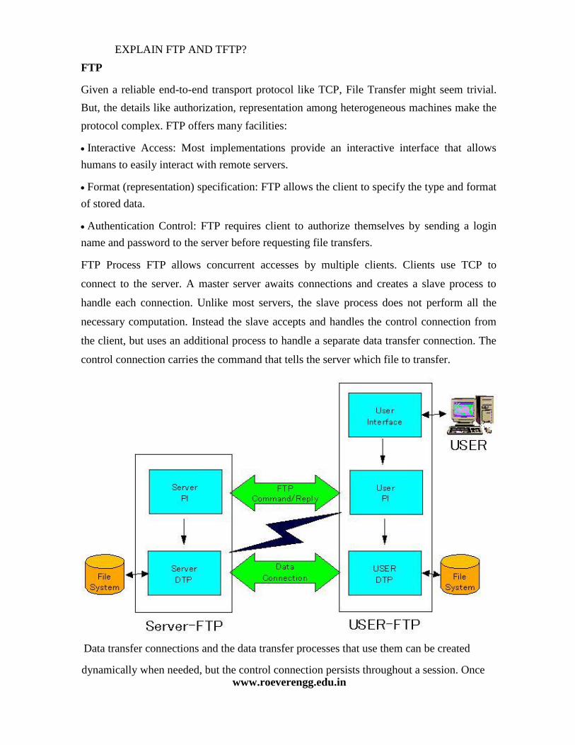
EXPLAIN FTP AND TFTP?
FTP Given a reliable end-to-end transport protocol like TCP, File Transfer might seem trivial.
But, the details like authorization, representation among heterogeneous machines make the
protocol complex. FTP offers many facilities: Interactive Access: Most implementations provide an interactive interface that allows
humans to easily interact with remote servers. Format (representation) specification: FTP allows the client to specify the type and format
of stored data. Authentication Control: FTP requires client to authorize themselves by sending a login
name and password to the server before requesting file transfers. FTP Process FTP allows concurrent accesses by multiple clients. Clients use TCP to
connect to the server. A master server awaits connections and creates a slave process to
handle each connection. Unlike most servers, the slave process does not perform all the
necessary computation. Instead the slave accepts and handles the control connection from
the client, but uses an additional process to handle a separate data transfer connection. The
control connection carries the command that tells the server which file to transfer.
Data transfer connections and the data transfer processes that use them can be created dynamically when needed, but the control connection persists throughout a session. Once
www.roeverengg.edu.in
the control connection disappears, the session is terminated and the software at both ends
terminates all data transfer processes. In addition to passing user commands to the server,
FTP uses the control connection to allow client and server processes to coordinate their use
of dynamically assigned TCP protocol ports and the creation of data transfer processes that
use those ports. Proxy commands - allows one to copy files from any machine to any other arbitrary
machine ie. the machine the files are being copied to need not be the client but any other
machine. Sometimes some special processing can be done which is not part of the
protocol. eg. if a request for copying a file is made by issuing command 'get file_A.gz' and
the zipped file does not exist but the file file A does , then the file is automatically zipped
and sent. Consider what happens when the connection breaks during a FTP session. Two
things may happen, certain FTP servers may again restart from the beginning and whatever
portion of the file had been copied is overwritten. Other FTP servers may ask the client
how much it has already read and it simply continues from that point.
TFTP TFTP stands for Trivial File Transfer Protocol. Many applications do not need the full
functionality of FTP nor can they afford the complexity. TFTP provides an inexpensive
mechanism that does not need complex interactions between the client and the server.
TFTP restricts operations to simple file transfer and does not provide authentication.
Diskless devices have TFTP encoded in read-only memory (ROM) and use it to obtain an
initial memory image when the machine is powered on. The advantage of using TFTP is
that it allows bootstrapping code to use the same underlying TCP/IP protocols. that the
operating system uses once it begins execution. Thus it is possible for a computer to
bootstrap from a server on another physical network. TFTP does not have a reliable stream
transport service. It runs on top of UDP or any other unreliable packet delivery system
using timeout and retransmission to ensure that data arrives. The sending side transmits a
file in fixed size blocks and awaits acknowledgements for each block before sending the
next.
Rules for TFTP
The first packet sent requests file transfer and establishes connection between server and
client. Other specifications are file name and whether it is to be transferred to client or to
the server. Blocks of the file are numbered starting from 1 and each data packet has a
header that specifies the number of blocks it carries and each acknowledgement contains
the number of the block being acknowledged. A block of less than 512 bytes signals end of
file. There can be five types of TFTP packets. The initial packet must use operation codes 1
or 2 specifying either a read request or a write request and also the filename. Once the read
request or write request has been made the server uses the IP address and UDP port number
of the client to identify subsequent operations. Thus data or ack messages do not contain
filename. The final message type is used to report errors. TFTP supports symmetric
retransmission. Each side has a timeout and retransmission. If the side sending data times
out, then it retransmits the last data block. If the receiving side times out it retransmits the
last acknowledgement. This ensures that transfer will not fail after a single packet loss. Problem caused by symmetric retransmission - Sorcerer's Apprentice Bug-When an ack
for a data packet is delayed but not lost then the sender retransmits the same data packet
which the receiver acknowledges. Thus both the acks eventually arrives at the sender and
the sender now transmits the next data packet once corresponding to each ack. Therefore
retransmissions of all the subsequent packets are triggered. Basically the receiver will
acknowledge both copies of this packet and send two acks which causes the sender in turn
to send two copies of the next packet. The cycle continues with each packet being
transmitted twice. TFTP supports multiple file types just like FTP ie. binary and ascii data.
TFTP may also be integrated with email. When the file type is of type mail then the
FILENAME field is to be considered as the name of the mailbox and instead of writing the
mail to a new file it should be appended to it. However this implementation is not
commonly used. Now we look at another very common application EMAIL
DEFINE DIGITAL SIGNATURE?
Digital Signatures Suppose A has to send a message to B. A computes a hash function of the message and
then sends this after encrypting it using its own private key. This constitutes the signature
produced by A. B can now decrypt it, recompute the hash function of the message it has
received and compare the two. Obviously, we would need the hash functions to be such that
the probability of two messages hashing to the same value is extremely low. Also, it should
be difficult to compute a message with the same hash function as another given message.
Otherwise any intruder could replace the message with another that has the same hash value
and leave the signatures intact leading to loss of integrity. So the message along with the
digital signature looks like this : Z + Privatesender ( Hash ( M ) ) Digital Certificates In addition to using the public key we would like to have a guarantee of talking to a known
person. We assume that there is an entity who is entrusted by everyone and whose public
key is known to everybody. This entity gives a certificate to the sender having the sender's
name, some other information and the sender's public key. This whole information is
encrypted in the private key of this trusted entity. A person can decrypt this message using
the public key of the trusted authority. But how can we be sure that the public key of the
authority is correct ? In this respect Digital signatures are like I-Cards. Let us ask ourselves
the question : How safe are we with I-Cards? Consider a situation where you go to the bank
and need to prove your identity. I-Card is used as a proof of your identity. It contains your
signature. How does the bank know you did not make the I-Card yourselves? It needs some
proof of that and in the case of I-Cards they contain a counter signature by the director for
the purpose. Now how does the bank know the signature I claim to be of the director indeed
belongs to him? Probably the director will also have an I-Card with a counter signature of a
higher authority. Thus we will get a chain of signing authorities. Thus in addition to signing
we need to prove that the signatures are genuine and for that purpose we would probably
use multiple I-Cards each carrying a higher level of signature-counter signature pair.

So in order to distribute the public key of this authority we use certificates of higher
authority and so on. Thus we get a tree structure where the each node needs the certificates
of all nodes above it on the path to the root in order to be trusted. But at some level in the
tree the public key needs to be known to everybody and should be trusted by everybody
too. Key Distribution Centre There is a central trusted node called the Key Distribution Center ( KDC ). Every node has
a key which is shared between it and the KDC. Since no one else knows node A's secret
key KA, KDC is sure that the message it received has come from A. When A wants to
communicate with B it could do two things: 1. A sends a message encrypted in it's key KA to the KDC. The KDC then sends a common
key KS to both A and B encrypted in their respective keys KA and KB. A and B can
communicate safely using this key. 2. Otherwise A sends a key KS to KDC saying that it wants to talk to B encrypted in the key
KA. KDC send a message to B saying that A wants to communicate with you using KS. There is a problem with this implementation. It is prone to replay attack. The messages are
in encrypted form and hence would not make sense to an intruder but they may be replayed
to the listener again and again with the listener believing that the messages are from the
correct source. When A send a message KA(M), C can send the same message to B by using
the IP address of A. A solution to be used is to use the key only once. If B sends the first
message KA(A,KS) also along with K(s,M), then again we may have trouble. In case this
happens, B should accept packets only with higher sequence numbers. To prevent this, we
can use: Timestamps which however don't generally work because of the offset in time between
machines. Synchronization over the network becomes a problem. Nonce numbers which are like ticket numbers. B accepts a message only if it has not
seen this nonce number before. In general, 2-way handshakes are always prone to attacks. So we now look at an another
protocol. Needham-Schroeder Authentication Protocol This is like a bug-fix to the KDC scheme to eliminate replay attacks. A 3-way handshake
(using nonce numbers) very similar to the ubiquitous TCP 3-way handshake is used
between communicating parties. A sends a random number RA to KDC. KDC sends back a
ticket to A which has the common key to be used. RA, RB and RA2 are nonce numbers. RA is used by A to communicate with the KDC. On
getting the appropriate reply from the KDC, A starts communicating with B, whence
another nonce number RA2 is used. The first three messages tell B that the message has
come from KDC and it has authenticated A. The second last message authenticates B. The
reply from B contains RB, which is a nonce number generated by B. The last message
authenticates A. The last two messages also remove the possibility of replay attack.
However, the problem with this scheme is that if somehow an intruder gets to know the key
KS ( maybe a year later ), then he can replay the entire thing ( provided he had stored the
packets ). One possible solution can be that the ticket contains a time stamp. We could also
put a condition that A and B should change the key every month or so. To improve upon
the protocol, B should also involve KDC for authentication. We look at one possible
improvement here. which is a different protocol.

Otway-Rees Key Exchange Protocol
In real life all protocols will have time-stamps. This is because we cannot remember all random
numbers generated in the past. We ignore packets with higher time stamps than some limit. So
we only need to remember nonces for this limit. Looking at these protocols, we can say that
designing of protocols is more of an art than science. If there is so much problem in agreeing on
a key then should we not use the same key for a long time. The key can be manually typed
using a telephone or sent through some other media