ROEVER COLLEGE OF ENGINEERING & … Machines Lab 1...Swinburne’s test of DC shunt motor. 8. Speed...
48
Page 1 of 48 ROEVER COLLEGE OF ENGINEERING & TECHNOLOGY Elambalur- Perambalur-621212 DEPARTMENT OF ELECTRICAL AND ELECTRONICS ENGINEERING ELECTRICAL MACHINES LABORATORY 1 Laboratory Observation Book Version - 01 CONTENTS SN Date Experiment Name Remarks 1. Open circuit and load characteristics of separately excited DC shunt generators. 2. Open circuit and load characteristics of self excited DC shunt generators. 3. Load characteristics of DC compound generator with differential and cumulative connection. 4. Load characteristics of DC shunt motor. 5. Load characteristics of DC compound motor. 6. Load characteristics of DC series motor. 7. Swinburne’s test of DC shunt motor. 8. Speed control of DC shunt motor 9. Hopkinson’s test on DC motor-generator set. 10. Load test on single-phase transformer and three phase transformer connections. 11. Open circuit and short circuit tests on single phase transformer. 12. Sumpner’s test on transformers. 13. Separation of no-load losses in single phase transformer. Name: Register Number: III Semester, II Year Academic Year 20 - 20
Transcript of ROEVER COLLEGE OF ENGINEERING & … Machines Lab 1...Swinburne’s test of DC shunt motor. 8. Speed...

Page 1 of 48
ROEVER COLLEGE OF ENGINEERING & TECHNOLOGY Elambalur- Perambalur-621212
DEPARTMENT OF ELECTRICAL AND ELECTRONICS ENGINEERING
ELECTRICAL MACHINES LABORATORY 1
Laboratory Observation Book Version - 01
CONTENTS
SN Date Experiment Name Remarks
1. Open circuit and load characteristics of separately excited DC
shunt generators.
2. Open circuit and load characteristics of self excited DC shunt
generators.
3. Load characteristics of DC compound generator with
differential and cumulative connection.
4. Load characteristics of DC shunt motor.
5. Load characteristics of DC compound motor.
6. Load characteristics of DC series motor.
7. Swinburne’s test of DC shunt motor.
8. Speed control of DC shunt motor
9. Hopkinson’s test on DC motor-generator set.
10. Load test on single-phase transformer and three phase
transformer connections.
11. Open circuit and short circuit tests on single phase
transformer.
12. Sumpner’s test on transformers.
13. Separation of no-load losses in single phase transformer.
Name:
Register Number:
III Semester, II Year
Academic Year 20 - 20

Roever College of Engineering & Technology / Department of EEE Page 2 of 48
SAFETY
1. Some of the experiments involve voltages that could conceivably lead to
serious injury or death. Therefore strict adherence to the following rules will
greatly decrease the probability that accidents will occur. However, no set of
rules can replace basic common sense, and all persons using the laboratory
are encouraged to constantly THINK SAFETY!
2. Always assume all circuits are energized unless you know with certainty that
they are not.
3. Use one hand to make connections.
4. Never work on electrical circuits with wet or moist hands.
5. Do not play with equipment not directly involved in your experiment.
6. When in the lab do not wear clothing or jewelry which could constitute a
health hazard. Shoes, preferably rubber soled ones, must be worn in the lab.
Long hair presents a hazard near moving parts of machinery.
7. It is important for safety reasons for anyone to easily trace out your test circuit
and, therefore do not work on a cluttered bench.
8. Never touch moving parts of machinery.
9. Think out ahead of time the consequences of closing or opening a switch.
10. Never alter an energized circuit unless you are certain of the outcome.
11. If you know or suspect that an accident is about to occur, take immediate
steps to prevent it but do not jeopardize your own safety in so doing.
THINK SAFETY

Roever College of Engineering & Technology / Department of EEE Page 3 of 48
EXP.NO. DATE:
OPEN CIRCUIT AND LOAD CHARACTERISTICS OF SEPARATELY
EXCITED DC SHUNT GENERATORS AIM: To obtain the OCC and load test of the given separately excited DC generator and hence to determine 1. Critical field resistance 2. Critical speed 3. OCC at the specified speed APPARATUS REQUIRRED NAME PLATE DETAILS:
Fuse Rating: 125% of rated current 125*17/100=21.25≈ 20 A
THEORY: A DC generator requires an excitation circuit to generate an induce voltage depending on whether excitation circuit consumes power for the armature of the machine or from separately require power supply. Generators may be classified as self excited or separately excited generators respectively. The induced emf in DC generators is given by the equation PфZN/60A volts. State P,Z,A are constants the above equation are written as Eg= KфN. I f the speed of the generator also maintained constant then Eg = Kф but the flux is directly proportional to the current Hence Eg =K2If.From the above equation it is clear that the induced emf is directly propositional to the field current when speed maintained constant,. The plot between the induced emf and the field current is known as open circuit characteristics of the DC generator. The typical shape of the characteristics is shown in fig. The induced emf when the field current is zero is known as residual voltage. This emf is due to the presence of a small amount of flux detained. In the field poles of the generator called residual flux. Once the OCC is obtained parameters such as critical field resistance, critical speed and the maximum voltage to which the machine can build up can be determined. If required the OCC at a different speeds can also be obtained. .Critical speed is minimum speed below which the generator shunt fails to excite.
PRECAUTIONS: 1. Remove the fuse carriers before wiring and start wiring as per the circuit diagram. 2. Keep the motor field rheostat at minimum resistance position and generator field rheostat at maximum
position 3. The SPST switch is kept open at the time of starting the experiment. 4. Fuse calculations. As the test is a no-load test the required fuse ratings are 20% of motor rated current. 5. Replace the fuse carriers with appropriate fuse wires after the circuit connections are checked by the
staff-in-charge.
Sl.No.
Apparatus Type Range Quantity
1. Voltmeter Digital (0-300)V 2
2. Ammeter Digital (0-20)A 1
3. Ammeter Digital (0-2)A 1
4 Rheostat 1200 ohm/0.8A 1
5. Rheostat 250 ohm/1.5A 1
6 Tachometer Digital 1
Armature Field
Rated Voltage:220Volts Rated Voltage:220Volts Shunt Motor
5hp Rated Current: 17Amps Rated Current:1Amps
Rated Voltage:220Volts Rated Voltage:220Volts Generator
3hp Rated Current: 13Amps Rated Current:0.8Amps
Rated Speed:1500 RPM (Revolution Per Minutes )
Make: Omega

Roever College of Engineering & Technology / Department of EEE Page 4 of 48
CIRCUIT DIAGRAM FOR OPEN CIRCUIT ON SEPARATELY EXCITED DC SHUNT GENERATOR
PROCEDURE 1. The circuit connections are made as per the circuit diagram in the shown figure. 2. Keeping the motor field rheostat in its minimum position generator field maximum position; and the
starter in its OFF position, the main supply is switched ON to the circuit. 3. The motor is started using the three point starter by slowly and carefully moving the starter handle from
its OFF to ON position. 4. The motor to brought to its rated speed by adjusting its rheostat and checked with the help of a
tachometer. 5. With the SPST switch open, the residual voltage is noted. 6. Now the SPST switch is closed and the Generator field Rheostat is varied in step and at each step the
field current (If) and the corresponding induced EMF (Eg) are recorded in the tabular column. This procedure is continued unit generator voltage reaches 120% of its rated value the machine is maintained constant.
7. After the experiment is completed the various rheostats are brought back to their original position in sequence and then main supply is switched off.
LOAD TEST ON SELF EXCITED DC GENERATOR AIM: To conduct the direct load test on the given self excited DC generator to plot.
1. External characteristics(Or load characteristics) 2. Internal characteristics(Or total characteristics)
THEORY: A DC generator works on the principle of Faraday’s Law of Electromagnetic induction, which says that, “Whenever a conductor is moved in magnetic field, an EMF is generated in it”. “The magnitude of induction EMF is directly proportional to the rate of change of flux”. The voltage equation for a DC shunt generator is given; by VL=Eg-IaRa; Under No Load Condition; Since Ia,Is negligibly small, From the above equation, the terminal voltage(VL),Is the no; load induced EMF(Eg), as the load on the generator increases ,
F1
F2
A1
A2
G
(500,
1.2A)
V +
_
(0 –
30
0V
) V
L
MC
+
_
220 V, DC
Supply
DPST
Swi
Tch 1
F1
F2
A1
A2
M
F L A
Three point starter
Fuse
(30
0
, 2A
)
Fuse
A + _ IA (0 – 20 A)
MC
A +
_ (0 - 2 A)
IF
+
_
220 V, DC
Supply
DPST S
Fuse
Fuse

Roever College of Engineering & Technology / Department of EEE Page 5 of 48
the load current and hence the armature current increases due to armature reaction the induced EMF in the armature decreases. Also increased armature current causes increase in IaRa drop. Hence the terminal voltage decreases with increase load. The plot between the terminal voltage (VL) and load current (IL) is known as the external of load characteristics. The plot between the induced EMF (Eg) and the armature current (Ia) is known as the internal or total characteristics. The type of graph of internal and external characteristics is shown in model graph. PRECAUTIONS: (Not to be included in the record) 1. Remove the fuse carriers before wiring and start wiring as per the circuit diagram. 2. Check the positions of the various rheostats as specified below;
*Motor field rheostat is kept at minimum resistance position *Generator field rheostat is kept at maximum resistance position
3. The DPST switch on the load side is kept open at the time of starting the experiment. 4. Fuse calculation. As this is a load test, the required fuse ratings are
120% of the motor rated current for supply side DPST. 120% of the generator rated current for load side DPST.
5. Replace the fuse carriers with appropriate fuse wires after the circuit connections are checked by the staff-in-charge.
CIRCUIT DIAGRAM FOR LOAD TEST ON SEPARATELY EXCITED DC SHUNT GENERATOR
Tabulation for Load Test:
Sl.no field current [If] in Amps
Load voltage [VL] in Volts
Load current [IL] in Amps
Armature Current Ia = IL+If Amps
Armature drop Ia Ra
In volts
Generated emf
[Eg = VL+IaRa] In volts
(0 – 20 A) IL
MC
F1
F2
A1
A2
G
(500,
1.2A)
+
_
DPST
S
wi Tch 2
Fuse
Load
V +
_
(0 –
300
V)
VL
MC
A + _
Var
iab
le
Res
isti
ve lo
ad
5 K
W
Fuse
+
_
220 V, DC
Supply
DPST
S
wi Tch 1
F1
F2
A1
A2
M
F L A
Three point starter
Fuse
(30
0
, 2A
)
Fuse
A + _ (0 – 20 A) Ia
MC
A
+
_ (0 - 2 A)
IF
+
_
220 V, DC
Supply
DPST S
Fuse
Fuse

Roever College of Engineering & Technology / Department of EEE Page 6 of 48
PROCEDURE: 1. The circuit connections are made as per the circuit diagram. 2. Keeping the motor field rheostat in which minimum position, generator field rheostats in maximum
position and the starter in its off position, the main supply is switched ON to the circuit. 3. The motor is started using the 3-point starter by slowly and carefully moving the starter handle from its
OFF to ON position. 4. The motor is brought to its rated speed by adjusting its field rheostat and checked with the help of the
tachometer. 5. With the DPST switch open, the potential divider is slowly varying until generator voltage is equal to its
rated value (220V). The terminal voltage and the field current are noted in the tabular column. 6. The DPST switch on the load side is now closed and the load on the generator is gradually increased in
steps. At each step the speed of the generator is checked and maintained constant at its rated value by adjusting the field rheostat of the motor. After satisfying this condition of each of loading, the terminal voltage(VL), field current(IF) and the load current (IL) are noted down in the tabular column.
7. This procedure is continued until the generator is loaded to 120%of its rated value. 8. Once the experiment is completed the load on the generator is gradually decreased, the various
rheostats are brought back to their original position in sequence and the main supply is switched OFF. PROCEDURE FOR MEASUREMENT OF ARMATURE RESISTANCE: 1. The circuit connections are made as per the circuit diagram. 2. Keeping the lamp load at the OFF position the main supply is switched ON. 3. The load is increased such that the current in the circuit is approximately adjusted to 25%,50% and 75%
of rated current of the generator and at these load conditions the armature voltage (V) and current(I) are noted in the tabular column.
CALCULATION: 1. Determinations of armature resistance(Ra);
The armature winding resistance is calculated using ohms law Ra=Va/Ia for each set of readings and the average of them is calculated. The effective resistance of the armature winding after taking into account the effect of temperature rise and skin effect is 1.2 times the average resistance Ra i.e. Ra(effective)=1.2 Ra(average).
2. To plot the internal characteristics, the armature current and the induced EMF are calculated using the expression, Ia=IL+IF and Eg=VL+IaRa(eff)
3. The plots of VL Vs IL and Eg Vs Ia are drawn to scale in the same graph sheet. Circuit diagram for find the generator armature resistance [Ra]
_
+
220 V, DC
Supply
DPST
Switch
Fuse
A + _
V +
_
(0 – 10 A) I
MC
(0 – 300V) VL
MC
Fuse
(50, 5A) A1
A2
G

Roever College of Engineering & Technology / Department of EEE Page 7 of 48
Procedure for find armature resistance Ra:
1. Connections are given as per circuit diagram 2. Check loading rheostat must be at maximum resistance position. 3. Close the DPST switch and vary the loading rheostat for various values in steps and noted the
corresponding voltmeter and ammeter reading. 4. Open the DPST switch after loading rheostat begins its initial position.
Tabulation for Finding Armature Resistance:
Sl.no Armature voltage Va Armature current I Ra = Va/ Ia
Model graph Open circuit characteristics Internal (Eg Vs Ia) and External (VL Vs IL) characteristics
MODEL CALCULATION:
Ia = IL+ IF Eg=VL + IaRa(eff)
RESULT: The direct load test on the given self-excited DC generator has been conducted and the internal & external characteristics are plotted. Review questions:
1. What is the difference between a separately excited dc generator and shunt generator? 2. If a DC shunt generator fails to build up voltage, what may be the probable reasons? 3. What is SPST? What is its use in this experiment? 4. What is the reason the presence of residual magnetism in the field poles? 5. Why does the terminal voltage decrease as the load current increases?
Eo
If
Field current
[If] in amps
Op
en c
ircu
it v
olt
age
in
Vo
lts
[Eo]
Eo Vs If
Load current [IL] in amps
Armature current [Ia] in amps
Load
vo
ltag
e in
Vo
lts
[VL]
Gen
erat
ed e
mf
in V
olt
s [E
g]
Eg Vs Ia
VL Vs IL
Roever College of Engineering & Technology / Department of EEE Page 8 of 48
EXP.NO. DATE:
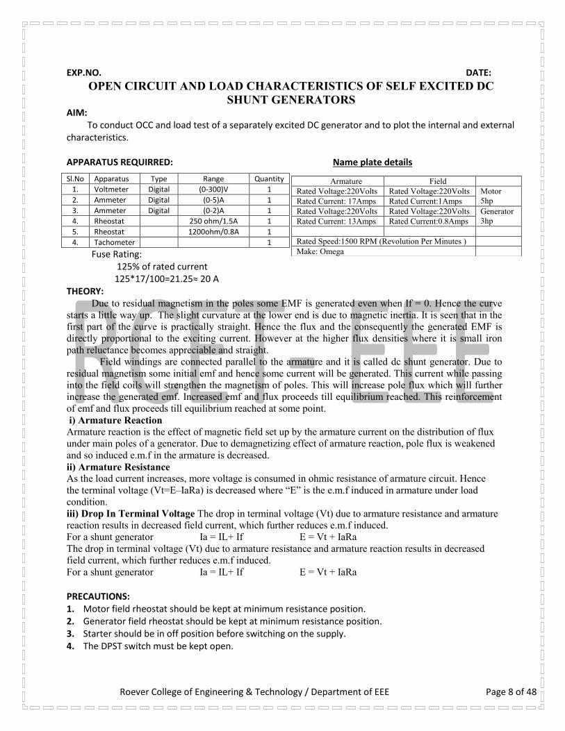
OPEN CIRCUIT AND LOAD CHARACTERISTICS OF SELF EXCITED DC
SHUNT GENERATORS AIM: To conduct OCC and load test of a separately excited DC generator and to plot the internal and external characteristics. APPARATUS REQUIRRED: Name plate details
Fuse Rating: 125% of rated current 125*17/100=21.25≈ 20 A
THEORY: Due to residual magnetism in the poles some EMF is generated even when If = 0. Hence the curve
starts a little way up. The slight curvature at the lower end is due to magnetic inertia. It is seen that in the
first part of the curve is practically straight. Hence the flux and the consequently the generated EMF is
directly proportional to the exciting current. However at the higher flux densities where it is small iron
path reluctance becomes appreciable and straight.
Field windings are connected parallel to the armature and it is called dc shunt generator. Due to
residual magnetism some initial emf and hence some current will be generated. This current while passing
into the field coils will strengthen the magnetism of poles. This will increase pole flux which will further
increase the generated emf. Increased emf and flux proceeds till equilibrium reached. This reinforcement
of emf and flux proceeds till equilibrium reached at some point.
i) Armature Reaction
Armature reaction is the effect of magnetic field set up by the armature current on the distribution of flux
under main poles of a generator. Due to demagnetizing effect of armature reaction, pole flux is weakened
and so induced e.m.f in the armature is decreased.
ii) Armature Resistance
As the load current increases, more voltage is consumed in ohmic resistance of armature circuit. Hence
the terminal voltage (Vt=E–IaRa) is decreased where “E” is the e.m.f induced in armature under load
condition.
iii) Drop In Terminal Voltage The drop in terminal voltage (Vt) due to armature resistance and armature
reaction results in decreased field current, which further reduces e.m.f induced.
For a shunt generator Ia = IL+ If E = Vt + IaRa The drop in terminal voltage (Vt) due to armature resistance and armature reaction results in decreased
field current, which further reduces e.m.f induced.
For a shunt generator Ia = IL+ If E = Vt + IaRa PRECAUTIONS: 1. Motor field rheostat should be kept at minimum resistance position. 2. Generator field rheostat should be kept at minimum resistance position. 3. Starter should be in off position before switching on the supply. 4. The DPST switch must be kept open.
Sl.No Apparatus Type Range Quantity
1. Voltmeter Digital (0-300)V 1
2. Ammeter Digital (0-5)A 1
3. Ammeter Digital (0-2)A 1
4. Rheostat 250 ohm/1.5A 1
5. Rheostat 1200ohm/0.8A 1
4. Tachometer 1
Armature Field
Rated Voltage:220Volts Rated Voltage:220Volts Motor
5hp Rated Current: 17Amps Rated Current:1Amps
Rated Voltage:220Volts Rated Voltage:220Volts Generator
3hp Rated Current: 13Amps Rated Current:0.8Amps
Rated Speed:1500 RPM (Revolution Per Minutes )
Make: Omega

Roever College of Engineering & Technology / Department of EEE Page 9 of 48
CIRCUIT DIAGRAM FOR OPEN CIRCUIT TEST ON SELF EXCITED DC SHUNT GENERATOR
PROCEDURE (OCC TEST) 1. Connections are given as per the circuit diagram. 2. Close the DPST switch. 3. The motor is started with the help of THREE POINT starter. 4. Adjust the motor speed to rated speed by adjusting motor field rheostat when the generator is
disconnected from the load by DPST switch 2. 5. By varying the generator field rheostat gradually, the open circuit voltage [Eo] and corresponding
field current (If) are tabulated up to 125 % of rated voltage of generator. The motor is switched off by using DPST switch 1 after bringing all the rheostats to initial position. CIRCUIT DIAGRAM FOR LOAD TEST ON SELF EXCITED DC SHUNT GENERATOR
PROCEDURE (LOAD TEST) 1. Connections are given as per the circuit diagram 2. The prime mover is started with the help of three point starter and it is made to run at rated speed
when the generator is disconnected from the load by DPST switch 2. 3. By varying the generator field rheostat gradually, the rated voltage [Eg] is obtained. 4. The ammeter and voltmeter readings are observed at no load condition. 5. The ammeter and voltmeter readings are observed for different loads up to the rated current by
closing the DPST switch 2.
(0 – 20 A) IL
MC
F1
F2
A1
A2
G
(5
00
, 1.2
A)
+
_
DPST S
wi Tch 2
Fuse
Load
V +
_
(0 –
30
0V
) V
L
A + _
Var
iab
le
Res
isti
ve lo
ad 5
KW
Fuse
+
_
220 V, DC
Supply
DP S T S
wi Tch 1
F1
F2
A1
A2
M
F L A
Three point starter
Fuse
(30
0
, 1.7
A)
Fuse
A + _ IA (0 – 20 A)
MC
A + _
IF(0 – 2 A)
MC
F1
F2
A1
A2
G
(50
0
, 1.2
A)
V +
_
(0 –
30
0V
) V
L
MC
+
_
220 V, DC
Supply
DPST
S
wi Tch 1
F1
F2
A1
A2
M
F L A
Three point starter
Fuse
(30
0
, 1.7
A)
Fuse
A + _ IA (0 – 20 A)
MC
A + _
(0 – 2 A)
MC

Roever College of Engineering & Technology / Department of EEE Page 10 of 48
6. After tabulating all the readings the load is brought to its initial position. 7. The motor is switched off by using DPST switch 1 after bringing all the rheostats to initial position. GRAPHS: 1. Field current Vs Generated voltage 2. Load current Vs Load voltage Tabulation for Open Circuit Test on Separately Excited D.C Shunt Generator:
Sl.no Open circuit voltage in
Volts [Eo]
Field current
in Amps [If]
Tabulation for Load Test:
Circuit diagram for find the generator armature resistance [Ra]
Procedure for find armature resistance Ra: 1. Connections are given as per circuit diagram 2. Check loading rheostat must be at maximum resistance position. 3. Close the DPST switch and vary the loading rheostat for various values in steps and noted the
corresponding voltmeter and ammeter reading. 4. Open the DPST switch after loading rheostat begins its initial position. To find Armature Resistance Ra:
SL.NO. Armature Current Ia (Amps)
Armature Voltage Va (Volts)
Armature Resistance Ra = Va/Ia (Ohms)
1
2
3
4
Average Ra
Sl.no Armature
current
[Ia] in
Amps
Load
voltage
[VL] in
Volts
Load
current
[IL] in
Amps
Armature
drop
Ia Ra
In volts
Generated
emf [Eg
=
VL+IaRa]
In volts
_
+
220 V, DC Supply
DPST
Switch
Fuse
A + _
V +
_
(0 – 10 A) I
MC
(0 – 300V) VL
MC
Fuse
(50, 5A) A1
A2
G
Roever College of Engineering & Technology / Department of EEE Page 11 of 48
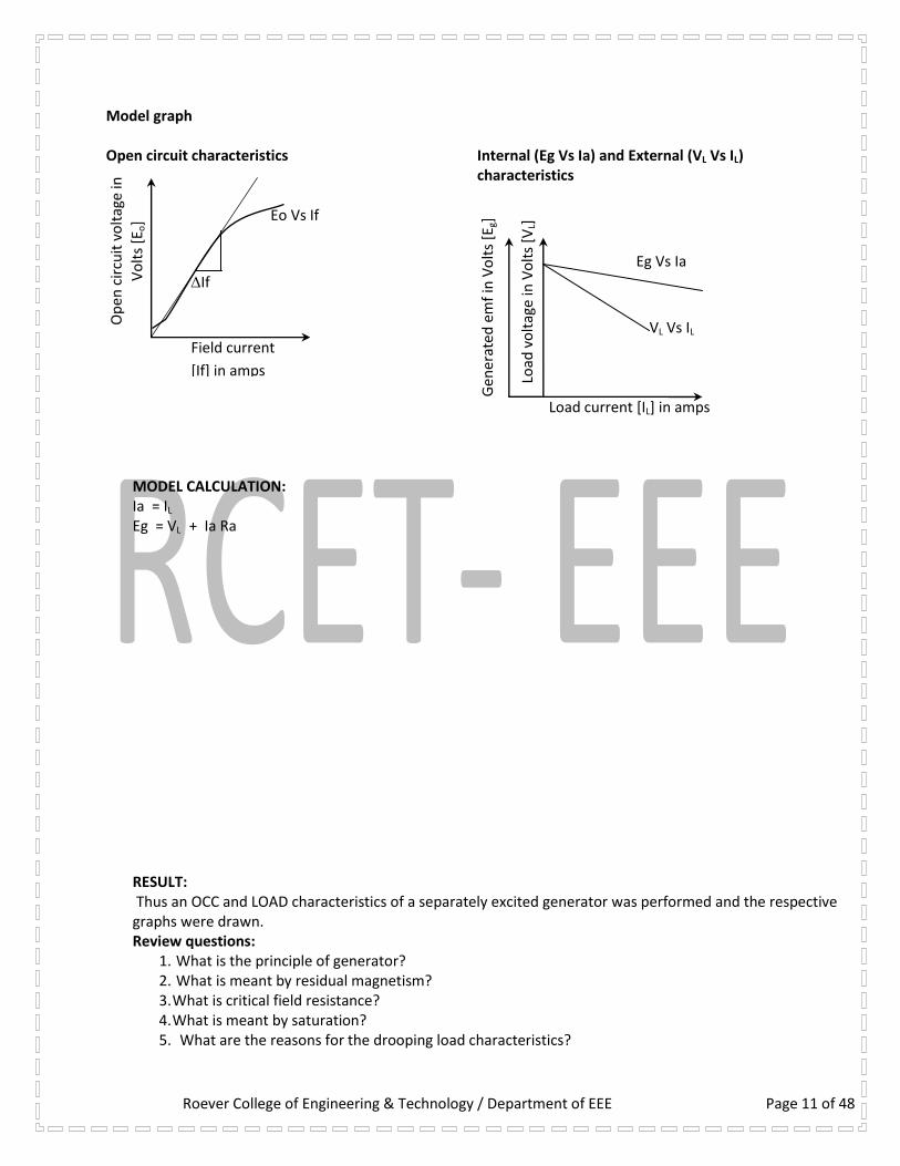
Model graph Open circuit characteristics
Internal (Eg Vs Ia) and External (VL Vs IL) characteristics
MODEL CALCULATION: Ia = IL Eg = VL + Ia Ra RESULT: Thus an OCC and LOAD characteristics of a separately excited generator was performed and the respective graphs were drawn. Review questions:
1. What is the principle of generator? 2. What is meant by residual magnetism? 3. What is critical field resistance? 4. What is meant by saturation? 5. What are the reasons for the drooping load characteristics?
Load current [IL] in amps
Armature current [Ia] in amps
Load
vo
ltag
e in
Vo
lts
[VL]
Gen
erat
ed e
mf
in V
olt
s [E
g]
Eg Vs Ia
VL Vs IL
If
Field current
[If] in amps
Op
en c
ircu
it v
olt
age
in
Vo
lts
[Eo] Eo Vs If

Page 12 of 48
EXP.NO. DATE:
LOAD CHARACTERISTICS OF DC COMPOUND GENERATOR WITH
DIFFERENTIAL AND CUMULATIVE CONNECTION Aim: To conduct load test on DC compound generator and obtain the load characteristic curves
Exercise Obtain the following curves for cumulative, differential and shunt generator
a. IL Vs V for DC cumulative compound generator b. IL Vs V for DC differential compound generator All graphs should be drawn on the same graph sheet
Apparatus Required: Sl.no Name of the component type Range Quantity
1
2
3
4
5
6
Ammeter
Voltmeter
Rheostat
Rheostat
Tachometer
Variable resistive load
Digital
Digital
Wire wound
Wire wound
Digital / Analog
Star connected
0-20 A
0-300 V
300Ω, 1.7 A
300Ω, 1.2 A
-
5 KW
1
1
1
1
1
1
Name plate details:Motor HP
Speed
Type
Field Armature
Fuse rating: No Load: 10 % of rated current (full load current) = Load test: 125 % of rated current (full load current) = CIRCUIT DIAGRAM OF LOAD TEST ON COMPOUND GENERATOR
Precautions:
1. Motor field rheostat should be kept at minimum resistance position 2. Generator side field rheostat should be kept at maximum resistance position 3. Before starting the motor starter should be in off position 4. Initially the generator should be no load. 5. The machine should be run at its rated speed throughout the experiment.
Generator KW
Speed
Type
Field Armature
(0 – 20 A) IL
F1
F2
A1
A2
G
Y1 Y2
(50
0
, 1.2
A)
+
_
DPST
S
wi Tch 2
Fuse
Load
V +
_
(0 –
30
0V
) V
L
MC
A + _ V
aria
ble
Res
isti
ve lo
ad
5 K
W
Fuse
+
_
220 V, DC
Supply
DPST
S
wi Tch 1
F1
F2
A1
A2
M
F L A
Three point starter
Fuse
(30
0
, 1.7
A)
Fuse
IA IL

Roever College of Engineering & Technology / Department of EEE Page 13 of
48
Procedure: 1. Connections are given as per the circuit diagram. 2. The motor is started with the help of a starter. 3. Adjust the motor speed to rated speed using rheostat. 4. Voltage generated due to residual magnetism is noted. 5. The field excitation to the generator is increased in steps and the corresponding generated
voltage is noted. 6. This procedure is continued until the built up voltage is 10 % greater than the rated voltage. 7. Now close the switch and vary the load rheostat note down the current drawn by the load. 8. Again get the motor speed to rated speed by adjusting the field rheostat. 9. Next vary the load and note the armature readings. 10. This procedure is continued until the load draws the rated current of the generator. 11. Now reverse the series field winding connection and repeat the procedure for doing load test and
note down the armature reading. Note:
If generating voltage of generator is increases with increasing of load current, it means generator is running under cumulative mode.
If generating voltage of generator is increases with decreasing of load current, it means generator is running under differential mode.
Tabulation for Cumulative Mode:
Sl.no
Load
voltage in
Volts
Load
current in
Amps
Speed
in
RPM
Tabulation for Differential Mode:
Sl.no
Load
current in
Amps
Load
voltage in
Volts
Speed
in
RPM
Model graph: RESULT: Thus an LOAD characteristic of a compound generator was performed and the respective graphs were drawn. Review questions:
1. What is called as cumulative compound operation? 2. What is meant by differential compound operation? 3. What are functions of commutator? 4. What are the applications of compound generator?
Differential mode
Load
vo
ltag
e (V
L) in
Vo
lts
Load current (IL) in Amps
Cumulative mode
(VL Vs IL)

Roever College of Engineering & Technology / Department of EEE Page 14 of
48
EXP.NO. LOAD CHARACTERISTICS OF DC SHUNT MOTOR DATE:
AIM:
To conduct load test on D.C motor and to obtain performance characteristics
APPARATUS REQUIRED DC SHUNT MOTOR NAME PLATE DETAIL Sl. No. Apparatus Type Range Quantit
y
1. Voltmeter Digital (0-300)V 1
2. Ammeter Digital (0-20)A 1
3. Rheostat 230 ohm/1.5A 1
4. Tachometer Digital 1
Fuse Rating:
125% of rated armature current (12 Amps) 125*12/100=15 A
THEORY:
The shunt motor has a definite no load speed hence it does not run away when load is suddenly
thrown off provided the field circuit remains closed. The drop in speed from no-load to full load is
small hence this motor is usual referred to a constant speed motor.
The efficiency curve is usually of the same shape for all electric motors and generators. The
shape of efficiency curve and the point of maximum efficiency can be very considerable by the
designer, though it is advantageous to have an efficiency curve which is fairly flat. So that there is
little change in efficiency between load and 25% overload and to have the maximum efficiency as
near to the full load as possible.
From the curves it is observed that is certain value of current is required even when output is
zero. The motor input under no-load conditions goes to meet the various losses, occurring within the
machine.
As compared to other motors a shunt motor is said to have a lowest starting torque. But this
should not be taken off mean that is shunt motor is incapable of starting heavy load. Actually it means
that series and compound motor as capable of starting heavy load with les excess of current inputs
over normal values then the shunt motor and the consequently the depreciation on the motor will be
relatively less.
CIRCUIT DIAGRAM FOR LOAD TEST ON DC SHUNT MOTOR
PRECAUTIONS:
1. The motor field rheostat should be kept at minimum resistance position.
2. The motor should be started at no load condition.
3. The motor should be cooled by circulating water throughout the experiment.
4. Starter should be in off position before switching on the supply.
Armature Field
Rated Voltage:220Volts Rated Voltage:220Volts
Rated Current: 12Amps Rated Current:0.6Amps
Rated Speed:1500 RPM (Revolution Per Minutes )
Make: BENN
S1 S2
BRAKE DRUM
+
_
220 V, DC
Supply
D
P
S
T
Swi
tch
(300, 1.7A)
Field
rheostat Z
ZZ
A
AA
M
F L A
Three point starter
Fuse,
15A A + _
V +
_
(0 – 30 A) IL
Digital
MC
(0 – 300V) VL
Digital
IA
IZ

Roever College of Engineering & Technology / Department of EEE Page 15 of
48
5. The DPST switch must be kept open. 6. Before connecting the meters check the polarity and zero error.
PROCEDURE:
1. Connections are given as per the circuit diagram. 2. Observe the precaution and using three-point starter the motor is started to run at the
rated speed by adjusting the field rheostat if necessary. 3. The meter readings are noted at no load condition. 4. By using break drum with spring balance arrangement the motor is loaded and the
corresponding readings are noted up to the rated current. 5. After observation of all the readings the load is released gradually 6. The motor is switched off by using DPST switch.
TABULAR COLUMN FOR LOAD TEST ON DC SHUNT MOTOR
Radius of the brake drum (R) = in m Thickness of the belt (t) = in m
Sl N
o Load
Voltage in Volts
Load current
IL in Amps
Speed in rpm
Spring balance Reading
In kg
Input Power = VL*IL
in Watts
Torque T =
(S1~S2)*9.81*R
in NM
Output Power
= 2лNT/
60 in Watts Ef
fici
ency
in
%
S1 S2 S1S2
MODEL GRAPH (A) Electrical characteristics
(B) Mechanical characteristics
(C) Torque, Speed Vs Load current
in %
T in N-m
Speed in rpm
IL in Amps
N IL T %
Output power in watts
T Vs N
Spee
d (
N)
in r
pm
Torque ( T ) in N-m
Torq
ue
(T)
in N
-m
Spee
d (
N)
in r
pm
IL Vs N
Load current (IL) in Amps
IL Vs T

Page 16 of 48
MODEL CALCULATION:
Input power =VL*IL Watts
Output power = 2лNT/ 60 Watts
Torque T= (S1~S2)*9.81*R N-m, where R is the radius of the brake drum in meter Output power
Efficiency η = x 100
Input power
GRAPHS:
1. Output power Vs efficiency
2. Output power Vs current
3. Output power Vs torque
4. Output power Vs speed
5. Speed Vs torque
RESULT:
Thus the load test on D.C shunt motor was performed and the respective graphs were drawn.
Review questions: 1. Why should the field rheostat be kept in the position of minimum resistance?
2. What is the loading arrangement used in a dc motor?
3. How can the direction of rotation of a DC shunt motor be reversed?
4. What are the mechanical and electrical characteristics of a DC shunt motor?
5. What are the applications of a DC shunt motor?

Roever College of Engineering & Technology / Department of EEE Page 17 of
48
LOAD CHARACTERISTICS OF DC COMPOUND MOTOR Exp no: Date : Aim: To conduct load test on DC compound motor and draw the characteristic curves Exercise
Draw the following characteristic curves for DC compound motor a. Output Vs η% b. Output Vs T c. Output Vs N d. Output Vs IL e. Torque Vs N
Apparatus Required: Sl.no Name of the component type Range Quantity
1
2
3
4
Ammeter
Voltmeter
Rheostat
Tachometer
MC
MC
Wire wound
Digital / Analog
0-15 A
0-300 V
300Ω, 1.7 A
-
1
1
1
1
Name plate details: MOTOR
Fuse rating calculation for field and armature: Load test 125 % of rated current CIRCUIT DIAGRAM FOR LOAD TEST ON DC COMPOUND MOTOR
Formulae Used:
(i) Torque = )2
(81.9)~( 21
tRSS in N-M S1, S2 – spring balance readings in Kg
R- Break drum radius in m (ii) Input power = V x I in Watts
(iii) Output power = 2NT / 60 in Watts N – Speed of the motor in RPM (iv) Percentage of efficiency = (Output power /Input power) x 100.
+
_
220 V, DC
Supply
D
P
S
T
S
w
i
tc
h
F1
F2
A1
A2
M
F L A
Four point starter Fuse
S1 S2
BRAKE DRUM
Y1 Y2 A + _
(0 – 15 A) IL
MC
V +
_
(0 – 300V) VL
MC
N
(300,
1.7A)

Roever College of Engineering & Technology / Department of EEE Page 18 of 48
Precautions 1. Starter should be in off position before switching on the supply. 2. The DPST switch must be kept open. 3. The motor field rheostat must be kept at minimum resistance position 4. There should be no load on the motor at the time of starting. 5. Before connecting the meters check the polarity and zero error. Procedure for DC Compound motor 1. Connections are given as per the circuit diagram. 2. Observe the precaution and using four-point starter the motor is started to run at the rated speed by
adjusting the field rheostat if necessary. 3. The meter readings are noted at no load condition. 4. By using break drum with spring balance arrangement the motor is loaded and the corresponding readings
are noted up to the rated current. 5. After observation of all the readings the load is released gradually 6. The motor is switched off by using DPST switch. TABULATION FOR LOAD TEST ON DC COMPOUND MOTOR Radius of the brake drum (R) = in m Thickness of the belt (t) = in m
Sl
No
Load
Voltage
in Volts
Load
current
I Amps
speed
in rpm
Spring balance
Reading
In kg
Input
Power
in
Watts
Torque
in NM
Output
Power
in
Watts
Efficiency
in %
S1 S2 S1S2
MODEL GRAPH (A) Electrical characteristics
in %
T in N-m
Speed in rpm
IL in Amps
N IL T %
Output power in watts

Roever College of Engineering & Technology / Department of EEE Page 19 of 48
(B) Mechanical characteristics
(C) Torque, Speed Vs Load current
Model calculation: Graph:
Output Vs η%
Output Vs T
Output Vs N
Output Vs IL
Torque Vs N Result:
Thus the load test on D.C compound motor was performed and the respective graphs were drawn.
Review questions: 1. Why 4 point starter used in DC compound motor?
2. What is the loading arrangement used in a dc compound motor?
3. How can the direction of rotation of a DC compound motor be reversed?
4. What are the mechanical and electrical characteristics of a DC compound motor?
5. What are the applications of a DC compound motor?
T Vs N
Spee
d (
N)
in r
pm
Torque ( T ) in N-m
Torq
ue
(T)
in N
-m
Spee
d (
N)
in r
pm
IL Vs N
Load current (IL) in Amps
IL Vs T

Roever College of Engineering & Technology / Department of EEE Page 20 of 48
EXP.NO. LOAD CHARACTERISTICS OF DC SERIES MOTOR DATE: AIM: To conduct load test on D.C series motor and to obtain performance characteristics APPARATUS REQUIRRED DC SERIES MOTOR NAME PLATE DETAIL
Sl.no Apparatus Type Range Quantity
1. Voltmeter Digital (0-300)V 1
2. Ammeter Digital (0-20)A 1
3. Tachometer Digital 1
Fuse Rating: 125% of rated current 125*12/100 =15 A
THEORY: The drop in speed with increased load is much prominent in series motor than in a shunt motor hence a series
motor is not suitable for application requiring a substantially constant speed. For a given current input a starting torque developed by a series motor is greater than that developed by a
shunt motor. Hence series motors are used where huge starting torques is necessary that means for cranes and traction purpose. In addition to huge starting torque there is another unique characteristic of series motor which makes this especially desirable for traction work that means when a load comes on a series motor it response by decreasing its speed and supplies the increased torque with a small increase in current. On the other hand a shunt motor under the same condition would hold its speed nearly constant and would supply the required increased torque with a large increase of input current. PRECAUTIONS:
1. Starter should be in off position before switching on the supply. 2. The motor should be started with some load 3. The motor should be stopped with some load. 4. Before connecting the meters check the polarity and zero error.
PROCEDURE: 1. Connect as per the circuit diagram 2. Close the DPST switch 3. Start the motor using two point starter 4. Note down the reading of voltmeter, ammeter, speed and spring balance reading. 5. Apply load in steps and note down the corresponding reading till the rated current is reached.
CIRCUIT DIAGRAM FOR LOAD TEST ON DC SERIES MOTOR
Formula used
Input power =VL*IL Watts Output power = 2лNT/ 60 watts
Armature Field
Rated Voltage:220Volts Rated Voltage:220Volts
Rated Current: 12Amps Rated Current: 12Amps
Rated Speed:1500 RPM (Revolution Per Minutes )
Make: BENN
S1 S2
BRAKE DRUM
+
_
220 V, DC
Supply
DPST Swi
tch
A
AA
M
L A
Two point starter Fuse, 15A
S SS A + _
(0 – 30 A) IL Digital
V +
_
(0 – 300V) VL Digital
N
Roever College of Engineering & Technology / Department of EEE Page 21 of 48
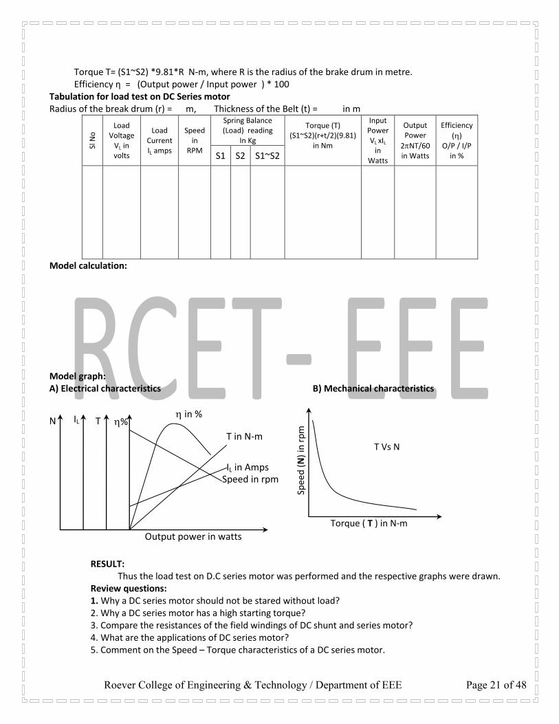
Torque T= (S1~S2) *9.81*R N-m, where R is the radius of the brake drum in metre. Efficiency η = (Output power / Input power ) * 100
Tabulation for load test on DC Series motor Radius of the break drum (r) = m, Thickness of the Belt (t) = in m
Sl N
o Load
Voltage VL in volts
Load Current IL amps
Speed in
RPM
Spring Balance (Load) reading
In Kg
Torque (T) (S1~S2)(r+t/2)(9.81)
in Nm
Input Power VL xIL
in Watts
Output Power
2NT/60 in Watts
Efficiency
() O/P / I/P
in % S1 S2 S1~S2
Model calculation: Model graph: A) Electrical characteristics B) Mechanical characteristics
RESULT: Thus the load test on D.C series motor was performed and the respective graphs were drawn. Review questions: 1. Why a DC series motor should not be stared without load? 2. Why a DC series motor has a high starting torque? 3. Compare the resistances of the field windings of DC shunt and series motor? 4. What are the applications of DC series motor? 5. Comment on the Speed – Torque characteristics of a DC series motor.
T Vs N
Spee
d (
N)
in r
pm
Torque ( T ) in N-m
in %
T in N-m
Speed in rpm IL in Amps
N IL T %
Output power in watts

Roever College of Engineering & Technology / Department of EEE Page 22 of 48
EXP.NO. DATE:
SWINBURNE’S TEST OF DC SHUNT MOTOR AIM: To predetermine the efficiency of a DC shunt machine by conducting the Swinburne’s Test 1. as a motor 2. as a generator NAME PLATE DETAILS: DC SHUNT MOTOR 5 HP Rated Voltage: 230 V Rated Current: 17 A Rated Speeds: 1500 RPM Excitation Voltage: 230 V DC APPARATUS REQUIRED:
SL.NO. APPARATUS RANGE TYPE QUANTITY
1 Ammeter 0 – 10 A MC 1 No.
2. Ammeter 0 – 1/2 A MC 1 No.
3. Voltmeter 0 – 300 V MC 1 No.
4 Voltmeter 0 – 5 V MC 1 No.
4. Rheostat 250 Ω, 1.5 A MC 1 No.
5. Rheostat 1200 Ω, 0.8 A MC 1 No.
6. Tachometer Digital 1 No.
FUSE RATING: Fuse rating = 40 % of rated current = 40/100 * 17 = 6.8 A ≈ 10 A THEORY: In this method the losses are measured separately and from their knowledge efficiency at any desired load can be predetermined. Hence the only running test needed is the no load test. This test is applicable to the machine in which flux is practically constant i.e shunt wound and compound wound machines. The machine is to run as a motor at its rated voltage. The speed is adjusted to rated speed with help of shunt field regulator. The no load current and field current are measured using ammeters. This test is convenient and economical because power required to test a large machine is small i.e. only input power is required. The efficiency can be predetermined at any load because constant losses are known. In this test we are not taking into account the change in iron loss from no load to full load. In this test it is impossible to know that whether commutation would be satisfactory at full load and whether temperature rise would be within specified limits. PRECAUTIONS: 1. The field rheostat must be kept in minimum resistance position. 2. The starter handle must be kept in OFF position before switching ON the supply. 3. The motor must be started at no load condition.

Roever College of Engineering & Technology / Department of EEE Page 23 of 48
PROCEDURE: 1. Connections are made as per the circuit diagram. 2. The supply is switched ON by closing the DPST switch. 3. The field rheostat is adjusted till the motor attains its rated speed. 4. The readings of the ammeters and voltmeter are noted under no load conditions. 5. The rheostat is brought back to the minimum position and the supply is switched OFF. 6. The DC resistance of the armature is determined using a voltmeter and an ammeter.
FORMULA: Constant Losses Wc = VIo – (Io – Ish)2 Ra Watts As a Motor: Input power = VLIL Watts Ia =IL – If Amps Armature Cu loss = Ia2 Ra Watts Total Loss = Wc + Cu loss Watts Output power = Input – Total loss Watts % Efficiency = Output/Input * 100 As a Generator: Ia =IL + If Amps Armature Cu loss = Ia2 Ra Watts Total Loss = Wc + Cu loss Watts Output power = VLIL Watts Input power = Output + Total loss Watts % Efficiency = Output/Input * 100 Formulae Used: Armature resistance [Ra] = 1.6x RDC in ohms Constant loss [WCO] = V IO – Iao
2 Ra in watts
Armature current [Ia] = ILIf in Amps Copper loss [WCU] = Ia
2 Ra in watts
+
_
220 V, DC
Supply
D
P
S
T
S
w
i
tc
h
(300, 1.7A)
Field
rheostat F1
F2
A1
A2
M
F L A
Three point
starter Fuse
A + _
V +
_
(0 – 10 A) I
MC
(0 – 300V) VL
MC
A + _
(0 – 2 A) IF
MC
Fuse
Roever College of Engineering & Technology / Department of EEE Page 24 of 48
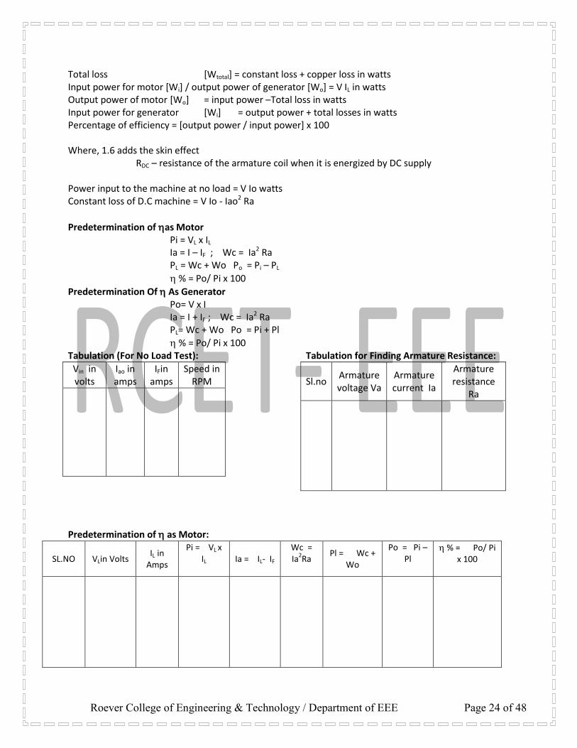
Total loss [Wtotal] = constant loss + copper loss in watts Input power for motor [Wi] / output power of generator [Wo] = V IL in watts Output power of motor [Wo] = input power –Total loss in watts Input power for generator [Wi] = output power + total losses in watts Percentage of efficiency = [output power / input power] x 100 Where, 1.6 adds the skin effect RDC – resistance of the armature coil when it is energized by DC supply Power input to the machine at no load = V Io watts Constant loss of D.C machine = V Io - Iao2 Ra
Predetermination of as Motor Pi = VL x IL Ia = I – IF ; Wc = Ia2 Ra PL = Wc + Wo Po = Pi – PL
% = Po/ Pi x 100
Predetermination Of As Generator Po= V x I Ia = I + IF ; Wc = Ia2 Ra PL= Wc + Wo Po = Pi + Pl
% = Po/ Pi x 100 Tabulation (For No Load Test):
Vin in volts
Iao in amps
IFin amps
Speed in RPM
Tabulation for Finding Armature Resistance:
Sl.no Armature voltage Va
Armature current Ia
Armature resistance
Ra
Predetermination of as Motor:
SL.NO VLin Volts IL in
Amps
Pi = VL x IL
Ia = IL- IF Wc = Ia
2Ra
Pl = Wc + Wo
Po = Pi – Pl
% = Po/ Pi x 100

Roever College of Engineering & Technology / Department of EEE Page 25 of 48
Predetermination of as Generator:
SL.NO V in
Volts I in
Amps
Po = V x I
Ia = I + If
Wc = Ia
2Ra
Pl = Wc + Wo
Pi = Po+ Pl
% = Po/ Pi x 100
Circuit diagram for find the generator armature resistance [Ra]
Procedure for find armature resistance Ra:
1. Connections arte given as per circuit diagram 2. Check loading rheostat must be at maximum resistance position. 3. Close the DPST switch and vary the loading rheostat for various values in steps and noted the
corresponding voltmeter and ammeter reading. 4. Open the DPST switch after loading rheostat begins its initial position.
Tabulation for Finding Armature Resistance:
Sl.no Armature voltage Va Armature current I Ra = Va/ Ia
_
+
220 V, DC
Supply
DPST
Switch
Fuse
A + _
V +
_
(0 – 10 A) I
MC
(0 – 300V) VL
MC
Fuse
(50, 5A) A1
A2
G

Roever College of Engineering & Technology / Department of EEE Page 26 of 48
Model calculation: GRAPHS: 1. Output power Vs efficiency ( as a motor) 2. Output power Vs efficiency ( as a generator)
RESULT: Thus the Swinburne’s test ( no load test) was conducted and the following efficiency were predetermined at different loads: 1. Efficiency as motor 2. Efficiency as generator.
Review questions: 1. What is the purpose of Swinburne’s test? 2. What are the constant losses in a DC machine? 3. What are the assumptions made in Swinburne’s test? 4. Why is the indirect method preferred to the direct loading test? 5. The efficiency of DC machine is generally higher when it works as a generator than when it works as a
motor. Is this statement true or false? Justify your answer with proper reasons. 6. How the motor speed increases when field current reduces? 7. What speed control is suitable for below rated speed? 8. What speed control is suitable for above rated speed?
in %
T in N-m
Speed in rpm IL in Amps
N IL T %
Output power in watts
Roever College of Engineering & Technology / Department of EEE Page 27 of 48
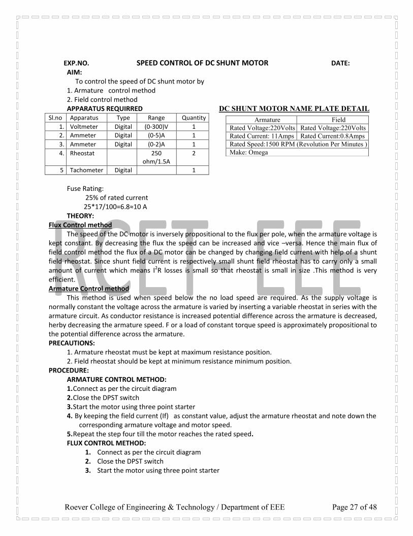
EXP.NO. SPEED CONTROL OF DC SHUNT MOTOR DATE: AIM: To control the speed of DC shunt motor by 1. Armature control method 2. Field control method APPARATUS REQUIRRED DC SHUNT MOTOR NAME PLATE DETAIL
Sl.no Apparatus Type Range Quantity
1. Voltmeter Digital (0-300)V 1
2. Ammeter Digital (0-5)A 1
3. Ammeter Digital (0-2)A 1
4. Rheostat 250 ohm/1.5A
2
5 Tachometer Digital 1
Fuse Rating: 25% of rated current 25*17/100=6.8≈10 A THEORY:
Flux Control method The speed of the DC motor is inversely propositional to the flux per pole, when the armature voltage is kept constant. By decreasing the flux the speed can be increased and vice –versa. Hence the main flux of field control method the flux of a DC motor can be changed by changing field current with help of a shunt field rheostat. Since shunt field current is respectively small shunt field rheostat has to carry only a small amount of current which means I2R losses is small so that rheostat is small in size .This method is very efficient. Armature Control method This method is used when speed below the no load speed are required. As the supply voltage is normally constant the voltage across the armature is varied by inserting a variable rheostat in series with the armature circuit. As conductor resistance is increased potential difference across the armature is decreased, herby decreasing the armature speed. F or a load of constant torque speed is approximately propositional to the potential difference across the armature. PRECAUTIONS:
1. Armature rheostat must be kept at maximum resistance position. 2. Field rheostat should be kept at minimum resistance minimum position.
PROCEDURE: ARMATURE CONTROL METHOD: 1. Connect as per the circuit diagram 2. Close the DPST switch 3. Start the motor using three point starter 4. By keeping the field current (If) as constant value, adjust the armature rheostat and note down the
corresponding armature voltage and motor speed. 5. Repeat the step four till the motor reaches the rated speed. FLUX CONTROL METHOD:
1. Connect as per the circuit diagram 2. Close the DPST switch 3. Start the motor using three point starter
Armature Field
Rated Voltage:220Volts Rated Voltage:220Volts
Rated Current: 11Amps Rated Current:0.8Amps
Rated Speed:1500 RPM (Revolution Per Minutes )
Make: Omega

Roever College of Engineering & Technology / Department of EEE Page 28 of 48
4. By keeping the armature voltage as constant value, adjust the field rheostat and note down the corresponding field current and motor speed.
Circuit Diagram for Speed Control of DC shunt Motor
TABULAR COLUMS for ARMATURE CONTROL METHOD & FIELD CONTROL METHOD
SL.NO.
Field Current If = 0.6 A
Field Current If = 0.5 A
Armature Voltage Va in V
Speed N in RPM
Armature Voltage Va in V
Speed N in RPM
1.
2.
3.
4.
5.
6.
7.
GRAPHS: 1. Field current Vs speed 2. Armature voltage Vs speed RESULT: Thus the speed of DC shunt motor was controlled by 1.Armature control method 2. Field control
method and the respective graphs were drawn. Review questions: 1. How does the speed of a DC shunt motor vary with armature voltage and field current? 2. Compare the resistance of the armature and field winding. 3. What is the importance of speed control of DC motor in industrial application? 4. Which is of the two method of speed control is better and why? 5. Why is the speed of DC shunt motor practically constant under normal load condition?
SL.NO.
Armature Voltage Va = 180 V
Armature Voltage Va = 170 V
Field Current
If in A
Speed N in RPM
Field Current If in A
Speed N in RPM
1.
2.
3.
4.
5.
6.
+
_
220 V, DC
Supply
DPST
Swi
tch
(650, 1A) Field
rheostat
Z
ZZ
A
AA
M
F L A
Three point starter
Fuse
A + _
V +
_
(0 – 10 A) IL Digital
(0 – 300V) VL Digital
A + _
(0 – 2 A) IF Digital
Fuse
(50, 5A)
Field
rheostat
Armature
rheostat
IA
IF

Roever College of Engineering & Technology / Department of EEE Page 29 of 48
EXP.NO. HOPKINSON’S TEST DATE: AIM:
To conduct the Hopkinson’s test on the given pair of DC machines and to obtain the performance curve.
NAME PLATE DETAILS:
Generator: Power : KW Voltage : V Speed : RPM Current : A
Motor: Power : HP Voltage : V Speed : RPM Current : A
APPARATUS REQUUIRED: SL.NO APPARATUS RANGE TYPE QTY
1 Voltmeter 2 Voltmeter 3 Ammeter 4 Ammeter 5 Tachometer 6 SPST knife switch
Fuse Rating: Fuse Rating = 125% of rated current = 125/100 * 17 ≈ 20 A Circuit diagram for HOPKINSON’S TEST THEORY: In this method full load test can be carried out on two shunt machines without wasting their outputs. The two machines are mechanically coupled and adjusted so that one of them runs as a motor and the other runs as a generator. The mechanical output of the motor drives the generator and the electrical output of the generator drives the motor. Due to losses the generator output is not sufficient to drive the motor and vice versa. The motor is started with no load. Then the field of one is weakened and the other is strengthened so that the former runs as motor and the latter as generator.
Initially the SPST switch is kept open. The field is adjusted so that the motor runs at rated speed. The voltage is adjusted by the field regulator until the voltmeter reads zero indicating that the voltage is same in polarity and magnitude as that of main supply. Then the switch is closed to parallel the machines. By adjusting the respective field regulators any load can be thrown on the machine. Generator current I1 can be adjusted to any desired value by increasing the excitation of generator or by reducing the excitation of motor.
3 POINT STARTER SPST
+
D
P
ST
Swi Tch
A1
M
F L A Fuse
25
0
, 1.5
A
_
F1
A2 Fuse
220 V, DC Supply
A1
G
A2
A + _
(0–300V) Vm, MC
V V
25
0
, 1.5
A
F2
(0–300V) Vg, MC
V (0–300V) Vg, MC
_
+
_
+
+
A +
_ A +
_
0-20A, IG
0-20A,
IGF, MC
+ `
0-20A,
IGMF, MC
F1
F2
A + _ 0-20A, IM

Roever College of Engineering & Technology / Department of EEE Page 30 of 48
The power required for this test is very small when compared to the full load power of two machines. As machines are tested under full load conditions the temperature rise and commutation quantities are observed. PRECAUTIONS:
1. The starter handle must be kept in OFF position at the time of switching on supply 2. The field rheostat of the motor must be kept in minimum resistance position. 3. The SPST switch is closed only when the voltmeter connected across the motor and generator shows
zero reading. PROCEDURE:
1. Connections are made as per the circuit diagram. 2. The supply is switched ON by closing the DPST switch. 3. The motor is started using three point starter. 4. The direction of rotation of the motor is checked if it is proper otherwise the field terminals of
the motor are interchanged. 5. The field rheostat of the motor is adjusted till the motor attains its rated speed. 6. The field rheostat of the generator of the generator till the voltmeter connected across the SPST
switch reads zero. 7. The SPST switch is closed. 8. The readings of the ammeter and voltmeter are noted and tabulated.
FORMULAE: 1. Armature Cu loss of generator = (Ifg + Ig)2 Ra Watts 2. Armature Cu loss of motor = (Ig + Im – Ifm)2 Ra Watts 3. Shunt Cu loss of generator = Vg Ifg Watts 4. Shunt Cu loss of motor = Vm Ifm Watts 5. Power drawn from supply = Vm Im Watts 6. Stray loss Wc = VmIm – (Ifg + Ig)2 Ra + (Ig + Im – Ifm)2 Ra + VgIfg + VmIfm Watts 7. Stray loss of single machine = Wc/2 8. Total loss in generator = Wc/2 + (Ifg + Ig)2 Ra + Vg Ifg Watts 9. Total loss in motor = Vm Ifm + (Ig + Im – Ifm)2 Ra + Wc/2 Watts 10. Output of generator = Vg Ig Watts 11. Input of generator = Output + losses 12. Efficiency of generator = output power/input power * 100 % 13. Input to the motor = Vm (Ig + Im) Wattts 14. Output power of motor = Input – losses Watts 15. Efficiency of motor = Output power/Input power *100%
HOPKINSON’S TEST- TABULAR COLUMNS
Motor Generator Armature Cu
Loss of Generator
Armature Cu Loss of Motor
Shunt Cu loss of generator
Vm Volts
Im Amps
Ifm Amps
Vg Volts
Ig Amps
Ifg Amps
(Ig+ Ifg)2 Ra Watts
(Ig+Im- Ifg)2
Ra Watts VgIfg Watts

Roever College of Engineering & Technology / Department of EEE Page 31 of 48
GRAPHS: 1. Output VS Efficiency (of generator) 2. Output VS Efficiency (of motor)
Model calculation
RESULT: Thus the Hopkinson’s test was conducted and the performance curve drawn.
VIVA QUESTIONS:
1. What is the purpose of Hopkinson’s test? 2. What are the advantages of Hopkinson’s test? 3. What are the conditions for conducting the test? 4. Why the adjustments are done in the field rheostat of generator and motor? 5. If the voltmeter across the SPST switch reads zero what does it indicate?
In % of motor
%
Output power in watts
In % of Generator

Roever College of Engineering & Technology / Department of EEE Page 32 of 48
EXP.NO. DATE:
LOAD TEST ON SINGLE-PHASE TRANSFORMER AND THREE PHASE
TRANSFORMER CONNECTIONS AIM: To conduct load test on single phase transformer and to obtain percentage efficiency & regulation. APPARATUS REQUIRRED:
Sl.No Apparatus Type Range Quantity
1. Voltmeter MI (0-300)V 2
2.` Ammeter MI (0-5)A 2
3. Lamp load 3KW/230 V 1
4. 1ф Transformer 1 KVA, 230/230V 1
5. Wattmeter UPF 0-300/5A 2
6. Auto Transformer 230V/0-270 V 1
NAME PLATE DETAILS
Single Phase Transformer Primary Voltage: 230 V Secondary Voltage: 115 V Capacity: 1 KVA Frequency: 50 Hz
Fuse Rating: 125% of rated current 125*4.34 /100 ≈ 5 A THEORY: When the secondary is loaded the secondary current I2 is setup. The magnitude and phase of I2
with respect to V2 is determined by the characteristics of the load. The secondary current sets up its own mmf and hence its own flux ф2 which is in opposition to main primary flux ф which is due to I0 the secondary ampere turns N2*I2 are known as demagnetizing ampere turns .The opposing secondary flux I2 weakens the primary flux ф momentary. Hence primary back Emf E1 tends to be reduced. For a moment V1 gain the upper hand over E1 and hence causes more current to flow in primary.
Let the additional primary current be I21 .It is known as load component of primary current. This current is antiphase with I21 the additional primary mmf N1*I2 sets up its own flux ф21 which is in opposite to ф2 and is equal to its magnitude. Hence the two cancel each other out. So the magnetic effects of secondary current I2 are immediately neutralized by the additional primary current I21.Hence whatever the load conditions be, the net flux passing through core is approximately the same as no-load. PRECAUTIONS: 1. The autotransformer should be kept at minimum voltage position. 2. Before switching off the supply the variac should be brought back to0 minimum voltage position. PROCEDURE: 1. Connect as per the circuit diagram 2. Close the DPST switch 3. Adjust the Auto transformer till the rated voltage is reached 5. Note down the readings of primary voltmeter, ammeter and wattmeter& secondary voltmeter, ammeter and wattmeter 6. Apply load in steps and note down the corresponding reading till the rated current is reached.

Roever College of Engineering & Technology / Department of EEE Page 33 of 48
LOAD TEST ON SINGLE PHASE TRANSFORMER
LOAD TEST ON SINGLE PHASE TRANSFORMER
TABULAR COLUMN
mf1 = mf2 = MODEL CALCULATION:
Output power % Efficiency η = X 100 Input power E0 – V % Regulation = X 100 V
GRAPHS: 1. Output power Vs efficiency 2. Output power Vs % regulation
SL.NO.
Primary Voltage
V1
Primary Current
I1
W1 Sec. Voltage
V2
Sec. Current
I2
W2 Input Power
W1 x mf1
Output Power
W2 x mf2 Effi
cie
ncy
%
R
egu
la
tio
n
%
1
2
3
4
5
6
(0-2A) MI IO1
P
N
150V, 2A, LPF
L M
C V
~ V
~ A
A
C
B
(0-150V) MI
VO1
1, Autotransformer 230V/ (0-270V)
D
P
S
T
S
w
i
t
c
h
230 V, 50Hz, 1,
AC Supply
P1
P2
S1
S2
1, 110/230V, 3VA step up transformer
~ V (0-150V) MI VO2
150V
NL
Roever College of Engineering & Technology / Department of EEE Page 34 of 48
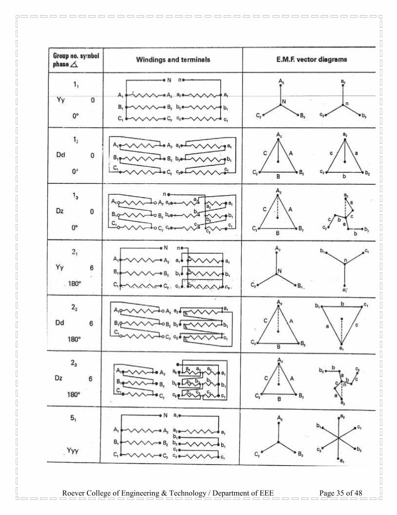
MODES OF CONNECTIONS: 1. Yyo-Normal star (HV)/Normal star (LV) 2. Yyo-Normal star (HV)/Reverse star (LV) 3. Yvl-Normal star (HV)/Normal delta (LV) 4. Ydll-Normal star (HV)/Reverse delta (LV) 5. Ddo-Normal delta (HV)/Reverse delta (LV) 6. D6-Normal delta (HV)/Reverse delta (LV) 7. Dy11-Normal delta (HV)/Normal star (LV) 8. Dy1-Reverse delta (LV)/Normal star (LV). STAR/STAR (OR) Y/Y CONNECTION:
This connection is for high voltage transformer. The phase voltage 1/√3 of line voltage. The ratio of line voltage is 1/3 1 &2 signs is the same as the transformer ratio of each transformer. The phase shift of 30 b/w the phase voltage and line voltage both on primary and secondary side, this connection works only if the load is balanced with the unbalanced load.
The neutral point shift thereby voltage is unequal. The effect of unbalanced load can be illustrated by placing single load between phases of neutral on the secondary side. Another advantage of stabilizing the primary neutral by connecting it to the neutral of the generator is that it eliminates distortion in the secondary phase voltage. DELTA/DELTA CONNECTION:
This connection is for low voltage transformer. The ratio of transformation between primary and secondary line voltage is exactly as same as that of each transformer. There is an angular displacement between primary and secondary voltages. Moreover, there is no internal phase shift between phase and line voltage on the other side. Wye/DELTA (or)Y/A CONNECTIONS:
This connection is at the substation of the transmission line where the voltage is to be stepped down. The primary winding is Y-connected and ground neutral. The relation between secondary and primary line voltage is 1/√3 time’s transformer ratio of each transformer. There is 30 shift between primary and secondary line voltage which means that Y-Delta transformer bank cannot be parallel with either a Y-Y as Delta-Delta bank. Also third harmonic current flows through the delta to provide a sinusoidal flux. DELTA/Wye (or) DELTA/Y CONNECTIONS:
This connection is generally employed when it is necessary to step up the voltage. The neutral of the secondary is grounded for providing three phase 4 wire service. This connection can be used to serve both the 3 phase power equipment and single phase lighting circuit. This connections is not open to the floating neutral and voltage distortion because of the existence of delta connection, allows the path for the third harmonic current. It would be observed that the primary and secondary line voltage and line current are out of phase with the each other by 30 . Because of this 30 shift it is impossible to parallel such a bank with a delta-delta or Y-Y bank of transformer even though the voltage ratios are correctly adjusted. The ratio of secondary of primary voltage is √3 times the transformer ratio of each transformer.
Roever College of Engineering & Technology / Department of EEE Page 35 of 48

Roever College of Engineering & Technology / Department of EEE Page 36 of 48

Roever College of Engineering & Technology / Department of EEE Page 37 of 48
Table 1 shows the combinations that will operate in parallel, and table 2 shows the combinations that will not operate in parallel.
Table 1 – Operative Parallel Connections of Three-Phase Transformers
.
Table 2 – Inoperative Parallel Connections of Three-Phase Transformers
For delta-delta and wye-wye connections, corresponding voltages on the high-voltage and low-voltage sides are in phase. This is known as zero phase (angular) displacement. Since the displacement is the same, these may be paralleled. For delta-wye and wye-delta connections, each low-voltage phase lags its corresponding high-voltage phase by 30 degrees. Since the lag is the same with both transformers, these may be paralleled. A delta-delta, wye-wye transformer, or bank (both with zero degrees displacement) cannot be paralleled with a delta-wye or a wye-delta that has 30 degrees of displacement. This will result in a dangerous short circuit. Wye-wye connected transformers are seldom, if ever, used to supply plant loads or as GSU units, due to the inherent third harmonic problems with this connection. Delta-delta, delta-wye, and wye-delta are used extensively at Reclamation facilities. Some rural electric associations use wye-wye connections that may be supplying reclamation structures in remote areas. There are three methods to negate the third harmonic problems found with wye-wye connections: 1. Primary and secondary neutrals can be connected together and grounded by one common grounding conductor. 2. Primary and secondary neutrals can be grounded individually using two grounding conductors. 3. The neutral of the primary can be connected back to the neutral of the sending transformer by using the
transmission line neutral.
PRECAUTIONS: 1. The DPST switch is closed only if the circuit connections are correct. 2. The variac should be kept in minimum voltage position before switching ON the supply. 3. Before switching OFF the supply, the variac should be brought back to its minimum voltage position. PROCEDURE:
1. Connections are given as per the circuit diagram. 2. The connection was delta-delta connection. 3. 415V was supplied to the primary side.

Roever College of Engineering & Technology / Department of EEE Page 38 of 48
4. One load was supplied to the primary side, readings of ammeter, voltmeter are noted down.
5. Readings are tabulated.
RESULT: Thus the three phase transformer was connected in delta-delta and the voltage current relations were obtained.
Review questions: 1. What are the various types of three phase transformer connections? 2. What is meant by vector grouping? 3. State the relationship line voltage and phase voltage in star connection. 4. What are the different types of three phase transformers? 5. What are the applications of the different types of three phase transformers? 6. What is the principle of a transformer? 7. What are the types of transformer? 8. What are the applications of transformer? 9. Why is the capacity of a transformer specified as KVA and not as KW? 10. What is the condition for maximum efficiency of a transformer and at which load does it occur? 11. Why is the efficiency of a transformer higher than that of motors?
Roever College of Engineering & Technology / Department of EEE Page 39 of 48
EXP.NO. DATE:
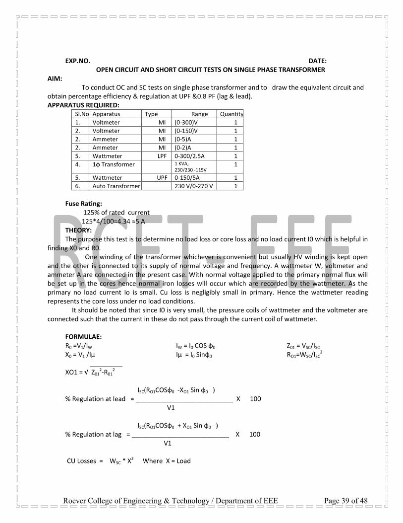
OPEN CIRCUIT AND SHORT CIRCUIT TESTS ON SINGLE PHASE TRANSFORMER AIM:
To conduct OC and SC tests on single phase transformer and to draw the equivalent circuit and obtain percentage efficiency & regulation at UPF &0.8 PF (lag & lead). APPARATUS REQUIRED:
Sl.No Apparatus Type Range Quantity
1. Voltmeter MI (0-300)V 1
2. Voltmeter MI (0-150)V 1
2. Ammeter MI (0-5)A 1
2. Ammeter MI (0-2)A 1
5. Wattmeter LPF 0-300/2.5A 1
4. 1ф Transformer 1 KVA, 230/230 -115V
1
5. Wattmeter UPF 0-150/5A 1
6. Auto Transformer 230 V/0-270 V 1
Fuse Rating: 125% of rated current 125*4/100=4.34 ≈5 A THEORY: The purpose this test is to determine no load loss or core loss and no load current I0 which is helpful in
finding X0 and R0. One winding of the transformer whichever is convenient but usually HV winding is kept open
and the other is connected to its supply of normal voltage and frequency. A wattmeter W, voltmeter and ammeter A are connected in the present case. With normal voltage applied to the primary normal flux will be set up in the cores hence normal iron losses will occur which are recorded by the wattmeter. As the primary no load current Io is small. Cu loss is negligibly small in primary. Hence the wattmeter reading represents the core loss under no load conditions.
It should be noted that since I0 is very small, the pressure coils of wattmeter and the voltmeter are connected such that the current in these do not pass through the current coil of wattmeter.
FORMULAE: R0 =V1/IW X0 = V1 /Iμ
IW = I0 COS ф0 Iμ = I0 Sinф0
Z01 = VSC/ISC RO1=WSC/ISC
2 _________ XO1 = √ Z01
2-R012
ISC(RO1COSф0 -XO1 Sin ф0 ) % Regulation at lead = ___________________________ X 100 V1 ISC(RO1COSф0 + XO1 Sin ф0 ) % Regulation at lag = ___________________________ X 100 V1 CU Losses = WSC * X2 Where X = Load

Roever College of Engineering & Technology / Department of EEE Page 40 of 48
Output power = KVA*1000*X *PF watts Input power = Output power + Losses Output power Efficiency = ____________ X 100 Input power
Fuse calculation for transformer (O.C and S.C test): Primary current IP = KVA rating of the transformer /primary voltage. Secondary current IS =KVA rating of transformer / secondary voltage. O.C test 10 % of rated primary current S.C test 125 % of rated secondary current Formulae Used: Open circuit test:
1. No load power factor ococ
oc
IV
W
)(cos 0
WOC = open circuit power in watts VOC = open circuit voltage in volts IOC = open circuit current in amps
2. No load working component resistance (RO); oOC
OC
OCosI
VR
in ohms
3. No load magnetizing component (XO); oOC
OC
OSinI
VX
in ohms
Short circuit test:
4. Equivalent impedance referred to HV side (Z02); SC
SC
OI
VZ 2 in ohms.
5. Equivalent resistance referred to HV side (R02); 22
SC
SCO
I
WR in ohms
6. Equivalent reactance referred to HV side (X02); 2
2
2
22 OOO RZX in ohms
7. Transformation ratio (K); 1
2
V
VK
8. Equivalent resistance referred to LV side (R01); 2
2
1K
RR O
O in ohms
9. Equivalent reactance referred to LV side (X01); 2
2
1K
XX O
O in ohms
Roever College of Engineering & Technology / Department of EEE Page 41 of 48
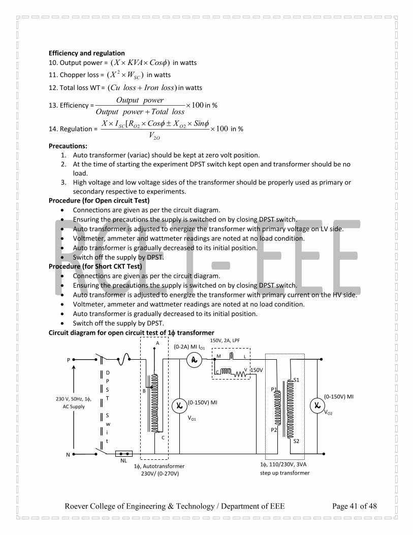
Efficiency and regulation
10. Output power = )( CosKVAX in watts
11. Chopper loss = )( 2
SCWX in watts
12. Total loss WT = )( lossIronlossCu in watts
13. Efficiency = 100 lossTotalpowerOutput
powerOutputin %
14. Regulation = 100[
2
22
O
OOSC
V
SinXCosRIX in %
Precautions: 1. Auto transformer (variac) should be kept at zero volt position. 2. At the time of starting the experiment DPST switch kept open and transformer should be no
load. 3. High voltage and low voltage sides of the transformer should be properly used as primary or
secondary respective to experiments. Procedure (for Open circuit Test)
Connections are given as per the circuit diagram.
Ensuring the precautions the supply is switched on by closing DPST switch.
Auto transformer is adjusted to energize the transformer with primary voltage on LV side.
Voltmeter, ammeter and wattmeter readings are noted at no load condition.
Auto transformer is gradually decreased to its initial position.
Switch off the supply by DPST. Procedure (for Short CKT Test)
Connections are given as per the circuit diagram.
Ensuring the precautions the supply is switched on by closing DPST switch.
Auto transformer is adjusted to energize the transformer with primary current on the HV side.
Voltmeter, ammeter and wattmeter readings are noted at no load condition.
Auto transformer is gradually decreased to its initial position.
Switch off the supply by DPST.
Circuit diagram for open circuit test of 1 transformer
(0-2A) MI IO1
P
N
150V, 2A, LPF
L M
C V
~ V
~ A
A
C
B
(0-150V) MI
VO1
1, Autotransformer 230V/ (0-270V)
D
P
S
T
S
w
i
t
c
h
230 V, 50Hz, 1,
AC Supply
P1
P2
S1
S2
1, 110/230V, 3VA
step up transformer
~ V
(0-150V) MI
VO2
150V
NL

Roever College of Engineering & Technology / Department of EEE Page 42 of 48
Circuit diagram for short circuit test of 1 transformer
Tabulation for OC Test multiplication factor:
Sl. no
Open circuit primary current
(IOC) In Amps
Open circuit primary voltage
(VOC) in Volts
Open circuit power (Woc) in Watts
Open circuit Secondary
voltage in volts Obsolete Actual
Tabulation for SC Test multiplication factor:
Sl. no
Short circuit primary current
(ISC) In Amps
Short circuit primary voltage
(VSC) in Volts
Short circuit power (Wsc) in Watts Short circuit
Secondary Current in Amps Obsolete Actual
(0-20A) MI, IO1
P
N
150V, 20A, UPF
L M
C V
~ V
~ A
A
C
B
(0-150V) MI
VO1
1, Autotransformer 230V/ (0-270V)
D
P
S
T
S
w
i
t
c
h
230 V, 50Hz, 1,
AC Supply
P1
P2
S1
S2
1, 110/230V, 3VA
step up transformer
150V
NL
~ A (0-30A) MI, ISC

Roever College of Engineering & Technology / Department of EEE Page 43 of 48
Predetermination of efficiency: Core (or) Iron loss (Wi) = Watts, KVA rating of Transformer = . Rated Short circuit current = Amps Short Circuit power (WSC) = .
Fraction of load
(X)
Short circuit
current
(ISC X) in Amps
Output power )( CosKVAX in
watts Copper loss
)( 2
SCWX
in watts
Total loss
SCiT WWW
in watts
Efficiency
TWpo
po
/
/
in % 0.2 0.4 0.6 0.8 1
¼
½
¾
1
Tabulation to find regulation: ISC = RO2= XO2= V2O=
Fraction of
load (X)
Value of Cos Value of Sin
% of Regulation
100[
2
22
O
OOSC
V
SinXCosRIX
1 0.8 0.6 0.4 0.2 1 0.8 0.6 0.4 0.2 1 0.8 0.6 0.4 0.2
Lag Lead Lag Lead Lag Lead Lag Lead
¼
½
¾
1
P
N
230 V, 1,
50Hz
AC Supply
Equivalent circuit of 1 transformer
Ro Xo
I2’ RO1’ XO1
Io
ZL
I1
Iw Io

Roever College of Engineering & Technology / Department of EEE Page 44 of 48
Model graph 1) Efficiency 2) Regulation
GRAPHS: 1. % Regulation Vs power factor 2. Output power Vs efficiency
RESULT: Thus the OC & SC tests on single phase transformer were performed and the respective graphs were drawn. Review questions:
1. What is the purpose of OC and SC tests? 2. Why the core is laminated? 3. What is meant by regulation? 4. Define the term transformation ratio? 5. What are the components of no load current?
Short circuit current ISC in Amps
1.0 pf
0.4 pf
0.8 pf
0.6 pf
0.2 pf
Effi
cien
cy in
%
Lagging pf
1.0 pf
0.4 pf
0.8 pf
0.6 pf
0.2 pf
+ ve
Reg
ula
tio
n
Leading pf Unity pf
- ve
Reg
ula
tio
n

Roever College of Engineering & Technology / Department of EEE Page 45 of 48
EXP.NO. DATE: SUMPNER’S TEST ON TRANSFORMERS
AIM: To predetermine the efficiency of the transformer at any desired load and power factor by conducting the Sumpners test. APPARATUS REQUIRED: SL.NO. APPARATUS TYPE RANGE QUANTITY
1. Ammeter 2. Voltmeter 3. Wattmeter 4 Transformer 5. Autotransformer 6. SPST knife switch
FUSE RATING: Fuse rating = KVA* 1000/Rated Voltage = 1000/230 = 4.34 A ≈ 5 A THEORY: This test provides data for finding the regulation, efficiency and heating under load condition and is employed only when two similar transformers are available. One transformer is loaded on the other and both are connected to the supply. The power taken from the supply is that necessary for supplying the losses of both transformers. Primaries of the two transformers are connected in parallel across the same AC supply, with switch S open and the wattmeter W1 reads the core losses for the two transformers. The secondary are connected that their potentials are in opposition to each other. This would be VAB = VCD and A is joined to C with B is joined to D in this case there would be no secondary current flowing around the loop formed by the two secondary. PRECAUTIONS:
1. The variac of the auto transformer should be kept at minimum voltage position. 2. Before switching off the supply the variac of the auto transformer should be brought
back to minimum voltage position. PROCEDURE:
1. Connect as per the circuit diagram. 2. Close the DPST switch. 3. Adjust the variac of the auto transformer connected to transformer 1 to get the rated
voltage. 4. Note down the reading of ammeter, voltmeter & wattmeter of transformer1. 5. Close the SPST switch if the voltmeter connected across the SPST switch reads zero. It not the
interchange the terminals of second transformer secondary to get zero reading at SPST switch.
6. Adjust the variac of the auto transformer connected to transformer 2 to get the rated current.
7. Note down the reading of ammeter, voltmeter & wattmeter of transformer2 8. Bring the auto transformer variac to zero position & switch off the supply.

Roever College of Engineering & Technology / Department of EEE Page 46 of 48
FORMULAE: Core losses Wi=W1/2 Watts Copper losses, Wc=W2/2*X2(Watts) Where, X=percentage of Load Total losses=Wc+Wi Watts Output power=KVA*100*X*p.f Watts Input power=Output power+losses Watts Efficiency=Output/Input*100
SUMPNER’S TEST TABULAR COLUMNS
PREDETERMINATION OF EFFICIENCY AT DIFFERENT LOADS
(i) At Unity Power Factor Load
Current I
Amps
% of full load X
(as decimal fraction)
Core Losses Wi = W1/2
Watts
Copper losses WC=
W2 /2 * X2
Watts
Total Losses Wi+WC
Watts
Output Power
Watts
Input Power
Watts
Efficiency η %
¼ (0.25) ½ (0.5) ¾ (0.75) 1(full load)
TFR.1 Current
I1 A
TFR.2 Current
I2 A
TFR.1 Voltage
V1 V
TFR.2 Voltage
V2
V
TFR.1 W1
Watts
TFR.2 W2
Watts
0 V
230 V
230 V
0 V
Two identical 1, 230/230V, 2KVA transformer
(0-150V) MI, V2
150V, 2A, LPF, W1
L M
C V
(0-150V) MI V1
150V
A (0-2A) MI I1
P
N
~ V
~ A
C
B
1, Autotransformer 1 230V/ (0-270V)
DPST witch 1
NL
230 V, 50Hz,
1, AC Supply
A (0-2A) MI I2
P
N
~ V
~ A
C
B
1, Autotransformer 2 230V/ (0-270V)
DPST Switch 2
NL
230 V, 50Hz, 1, AC Supply
150V, 2A, LPF, W2
L M
C V
(0-150V) MI, VO1
150V
~ V
0 V
0 V 230 V
230 V
SPST
Fuse Fuse
CIRCUIT DIAGRAM OF SUMPNER’S TEST ON TWO IDENTICAL TRANSFORMERS

Roever College of Engineering & Technology / Department of EEE Page 47 of 48
(ii) At 0.8 Power Factor (Lag) Load
Current I
Amps
% of full load X
(as decimal fraction)
Core Losses Wi = W1/2
Watts
Copper losses WC=
W2 /2 * X2
Watts
Total Losses Wi+WC
Watts
Output Power
Watts
Input Power
Watts
Efficiency η %
¼ (0.25) ½ (0.5) ¾ (0.75) 1(full load)
GRAPH: Output power Vs Efficiency at UPF and 0.8 power factor. RESULT: Thus the Sumpner’s test was performed and the efficiency was predetermined and the respective graphs were drawn. VIVA QUESTIONS:-
1. What is the purpose of conducting the Sumpner’s test? 2. What are the losses in a transformer? 3. Why LPF wattmeter is used in OC test? 4. Why UPF wattmeter is used in SC test? 5. What is meant by predetermination of efficiency?

Roever College of Engineering & Technology / Department of EEE Page 48 of 48
SEPARATION OF NO-LOAD LOSSES IN SINGLE PHASE TRANSFORMER