Rock Mechanics Laboratory Tests for Petroleum Applications - Rock mechanics laboratory te… ·...
23
Rock Mechanics Laboratory Tests for Petroleum Applications Rob Marsden Reservoir Geomechanics Advisor Gatwick
Transcript of Rock Mechanics Laboratory Tests for Petroleum Applications - Rock mechanics laboratory te… ·...

Rock Mechanics Laboratory Tests for Petroleum Applications
Rob MarsdenReservoir Geomechanics AdvisorGatwick

Summary• A wide range of well established and proven laboratory tests are available for petroleum rock
mechanics studies. Not only can these provide fundamental rock properties for characterization purposes or for well designs, the more specialist tests can provide information on how formations might behave when they are subjected to complex stress-paths around wellbores or within reservoirs at various stages during the field-life.
• Laboratory studies also provide methods for obtaining data that can not otherwise be derived from log data or history matching. For example, whilst strength properties can only be inferred empirically from log data, they may be determined directly from laboratory measurements. Similarly, whilst logs can provide data on dynamic elastic properties, their static (i.e., mechanical) elastic and non-elastic deformation parameters can only be derived from history matching or laboratory tests. Continuous log data combined with laboratory tests on selected samples can therefore provide complementary tools for use in petroleum geomechanics.
• When coupled with petrophysical studies, the simulation of realistic mechanical loading on a laboratory sample can also significantly enhance the reliability and usefulness of what might otherwise be routine petrophysical analyses.
• Laboratory techniques also exist for obtaining in situ stress data and, since these methods are based on fundamentally different processes to those employed in hydraulic fracturing etc., they provide useful and complementary adjuncts to rig-site methods.
• This presentation describes the type of rock mechanics tests available, including some of the more specialist studies as well as routine measurements. The types of equipment employed are introduced, and the data obtained from such laboratory programmes are explained in the context of their end-use for well engineering and reservoir engineering applications.

Rock Mechanics Tests
….. routinely involve measurements of:• Strength & deformation characteristics• Pore pressure responses under un-drained
loading• Porosity and bulk volume changes• Fluid transport characteristics• Influences of temperature, effective stress path
etc.
and measurements of:• Ultrasonic velocities• AE

Essential Capabilities:• Simulate deviatoric stresses at depth or in
proximity to a wellbore• Measure deformations and bulk/pore volume
changes
Systems typically incorporate :• Triaxial or confining cell• Load or reaction frame• Closed-loop loading, confining & pore pressure
systems• Heating systems (for HT applications)• Devices for measuring deformations, pore volume
changes, flow, ultrasonic velocities

Closed-Loop Controli.e., programmed rate of displacement ∆fp/∆t is selected
actual displacement fa is measureddifference fp-fa feeds back to the system controlsystem responds, correcting fp-fa to zero
Confining pressurecontroller LoggerProgram
fp
Amp fa-fp fa
Hydraulicpower
Servo-valveAmp
fa-fp
t
fp
t
f1 f2
Logger
Triaxialframe & cell
Program
Hydraulicpower
Piston displacement monitored
Pressureintensifier
Axial displacement
LoadSelect
feed-back
Correctingsignal
Correctingsignal
Axial loadcontroller
Cellpressure
Fluid reservoir
2000kN capacity system(configured for triaxial tests)
1600kN capacitydynamic system
Examples of Advanced Test Systems
3000kN capacityHPHT system
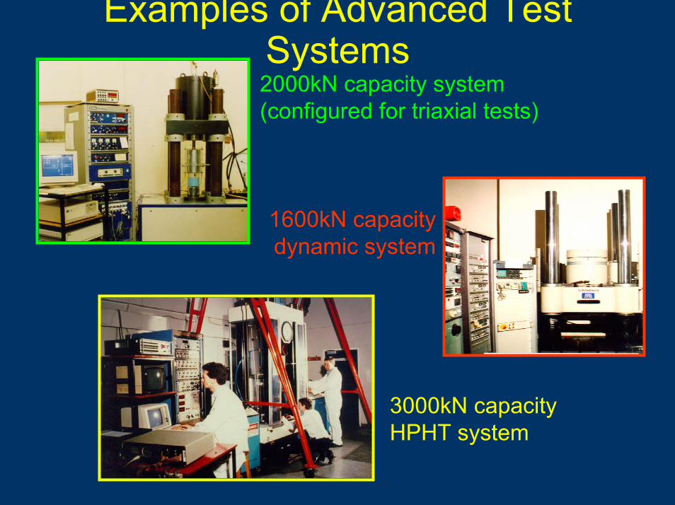
Uniaxial Compression Testing
010
2030
4050
0 2 4 6 8 10 12Axial strain (mstr)
Axi
al s
tress
(MP
a)
01
23
45
Mea
n di
amet
ral s
train
(mst
r)
Axial stress Mean diametral strain
Indirect methods:• Schmidt hammer• Brinell hardness• Penetrometer• Point load
• Static Young’s modulus (E) @ σ3‘ = 0• Static Poisson’s ratio (v) @ σ3‘ = 0• Uniaxial yield strength (σY)• Uniaxial compressive strength (UCS)
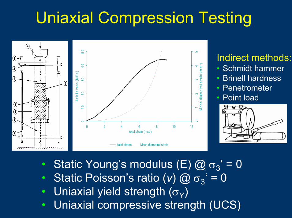
Triaxial Testing
Configuration forcoupled HPHT
Conventional triaxial compression:• Lateral stresses are σ2=σ3• Axial stress σ1 is increased
Triaxial extension:• Lateral stresses are σ1=σ2• Axial stress σ3 is reduced
Data obtained:• Triaxial yield strength (σY)• Peak strength• Residual strength (σR)• Static Young’s modulus (E) at confinement • Static Poisson’s ratio (v) at confinement

Shearstress
Normal stress
Curvedfailure envelope
Axial deviatorstress (σ1-σ3)
Axial strain
Increasingconfinement
Individualtest data
Minor ef fect ive st ress σ3’
Majoref fect ivestress σ1’
Uniaxial compressivestrength UCS
Tensile st rength
Possible states
Impossible state
Triaxial Deformation & Peak Strength Data
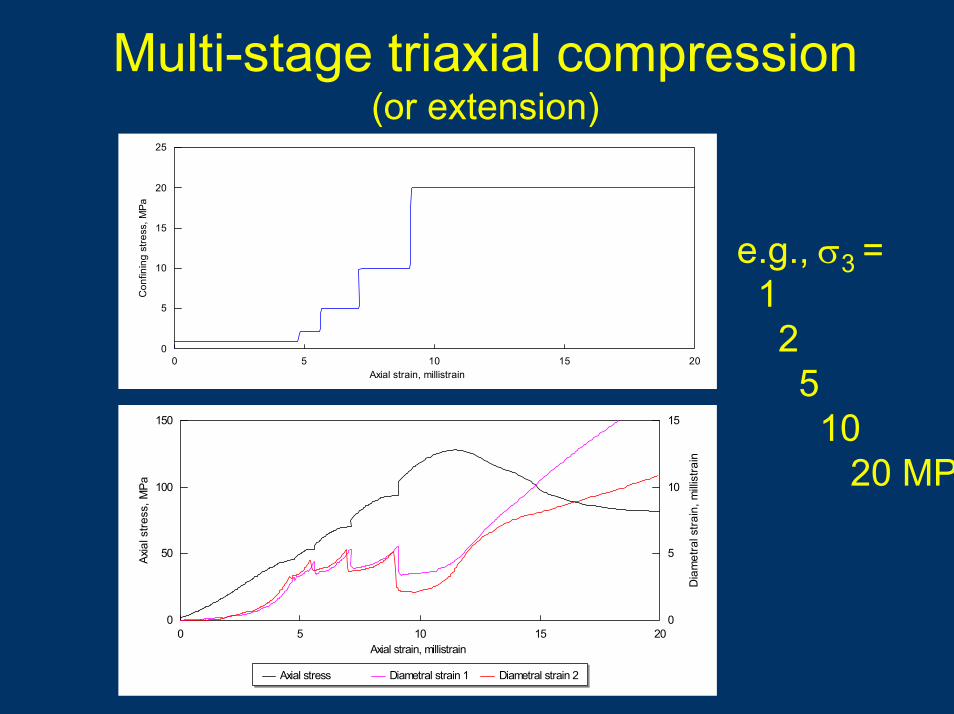
Multi-stage triaxial compression(or extension)
0 5 10 15 200
5
10
15
20
25
Axial strain, millistrain
Con
finin
g st
ress
, MPa
e.g., σ3 =12510
20 MP
0 5 10 15 200
50
100
150
0
5
10
15
Axial strain, millistrain
Axia
l stre
ss, M
Pa
Dia
met
ral s
train
, milli
stra
inAxial stress Diametral strain 1 Diametral strain 2
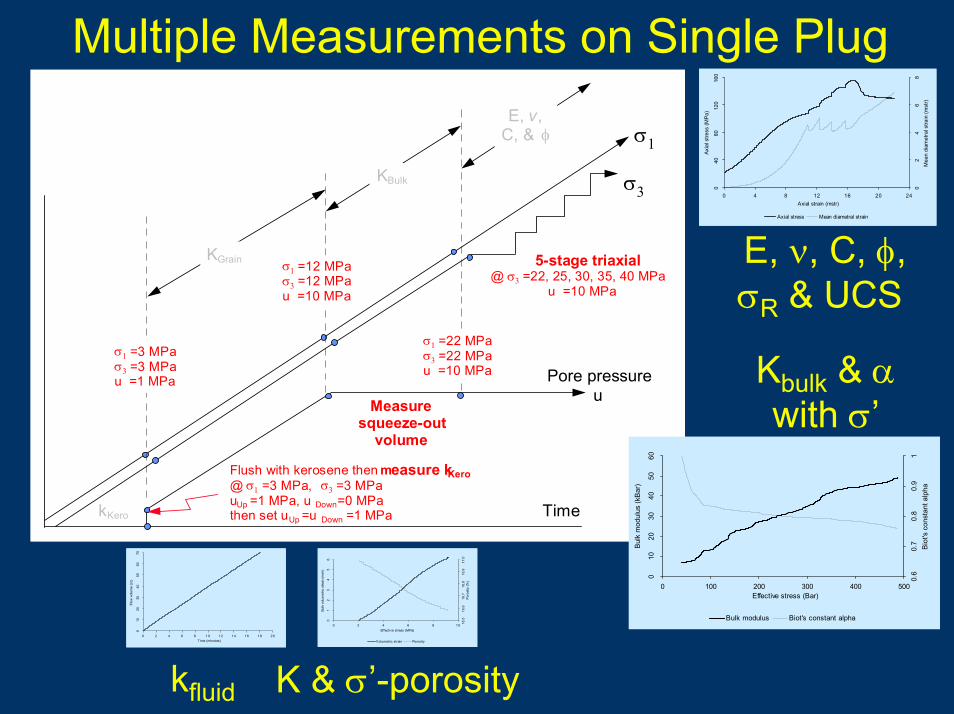
Multiple Measurements on Single Plug
σ1
Time
σ3
KGrain
KBulk
E, v,C, & φ
Pore pressureu
σ1 =3 MPaσ3 =3 MPau =1 MPa
σ1 =12 MPaσ3 =12 MPau =10 MPa
σ1 =22 MPaσ3 =22 MPau =10 MPa
Measuresqueeze-out
volume
5-stage triaxial@ σ3 =22, 25, 30, 35, 40 MPa
u =10 MPa
Flush with kerosene then measure kKero@ σ1 =3 MPa, σ3 =3 MPauUp =1 MPa, u Down=0 MPathen set uUp =u Down =1 MPakKero
01
23
45
6
0 2 4 6 8 10Effective stress (MPa)
Bulk
vol
umet
ric s
train
(mst
r)
16.5
16.6
16.7
16.8
16.9
17.0
Poro
sity
(%)
Volumetric strain Porosity
010
2030
4050
60
0 100 200 300 400 500Effective stress (Bar)
Bul
k m
odul
us (k
Bar
)
0.6
0.7
0.8
0.9
1B
iot's
con
stan
t alp
ha
Bulk modulus Biot's constant alpha
040
8012
016
0
0 4 8 12 16 20 24Axial strain (mstr)
Axi
al s
tress
(MP
a)
02
46
8M
ean
diam
etra
l stra
in (m
str)
Axial stress Mean diametral strain
010
2030
4050
6070
0 2 4 6 8 10 12 14 16 18 20Time (minutes)
Flow
vol
ume
(cc)
E, ν, C, φ,σR & UCS
Kbulk & αwith σ’
kfluid K & σ’-porosity

Stress- & strain-path triaxial tests… stresses/strains replicate a specific burial or engineering condition
q=σ1-σ3 (MPa)
34 36 38 40 420
2
4
6
8
10
12
14Uniaxial compaction
(Ko triaxial)(i.e. axial compaction
with total lateral restraint)
p’ =(σ1+2σ3)/3 - pore pressure (MPa

Conventional Ko Test
0 0.5 1 1.5 2 2.5 330
35
40
45
50
55
• Constant pore pressure• σaxial is increased• σlateral adjusted so εlateral = 0
εaxial (millistrains)
σaxial(MPa)
30 35 40 45 50 5530
32
34
36
38
40σlateral(MPa)
σaxial (MPa)
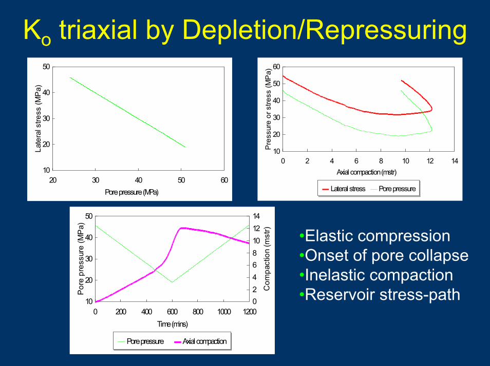
Ko triaxial by Depletion/Repressuring
20 30 40 50 6010
20
30
40
50
Pore pressure (MPa)
Late
ral s
tress
(MP
a)
0 2 4 6 8 10 12 1410
20
30
40
50
60
Axial compaction (mstr)
Pre
ssur
e or
stre
ss (M
Pa)
Lateral stress Pore pressure
0 200 400 600 800 1000 120010
20
30
40
50
02468101214
Time (mins)
Por
e pr
essu
re (M
Pa)
Com
pact
ion
(mst
r)
Pore pressure Axial compaction
•Elastic compression•Onset of pore collapse•Inelastic compaction•Reservoir stress-path

Coupled TestsAll these mechanical measurements can be undertake in conjunction with:• Ultrasonic measurements• Poro-perm (axial and lateral)• Electrical properties• Rel-perm• Cap pressure• Temperature• Fluid interactions (swelling & core-flood)
allowing the investigation of:• Coupled properties and behaviour • Stress-path and effective stress effects

Coupled Ultrasonic/Mechanical(VP, VS1 & VS2, & also transverse transmission)
Triaxialcell
Pulser
Digitaloscilloscope
Switch
Switch
T’ducer
T’ducer
Sleeve
Pre- amp
PC
Printer
Typicallyfrequencyresponse
200kHz-1MHz
VP, VS & dynamic elastic moduli• at confinement• under deviatoric loading,• at varying degrees of saturation etc.

σ1 > σ2 > σ3
Primarily a research tool
True Triaxial Testing
Coupled rock mechanical/petrophysical measurement
Poro-perm Rel-perm Stress-path etc.Ultrasonic (VP, VS1 & VS2) AEStrength Deformation Electrical

Wellbore stability Radial flowCavity completions Fracture treatmentsThermal fractures PerforationsFluid interactions Plasticity corrections
Overburden
Confinement
Porefluid
Wellpressure
TWC Studies
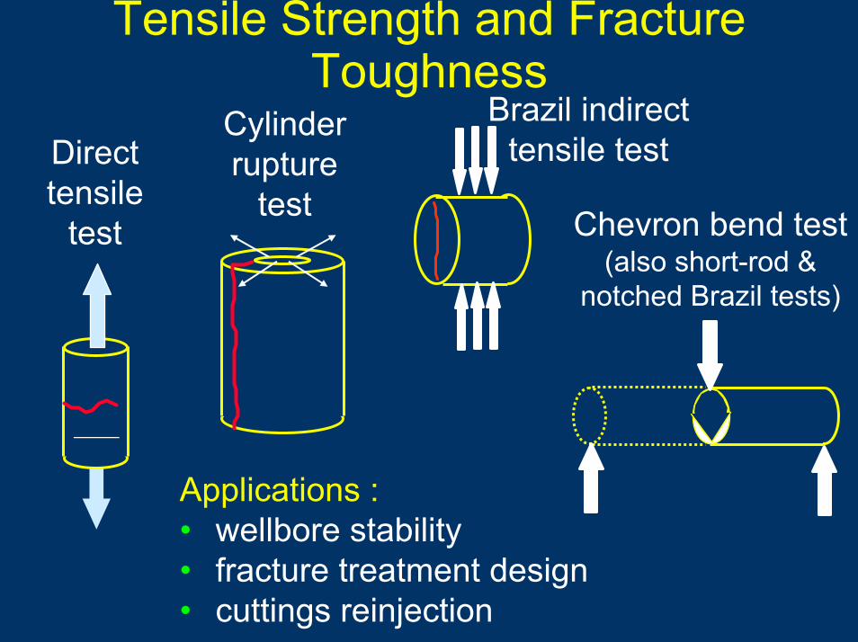
Applications :• wellbore stability • fracture treatment design• cuttings reinjection
Directtensile
test
Brazil indirecttensile test
Cylinderrupture
test Chevron bend test(also short-rod &
notched Brazil tests)
Tensile Strength and Fracture Toughness

Fracture Properties• Stress/pore pressure effects on fracture conductivity• Shear and normal stiffnesses• Shear strength• Residual strength
Franklin shear box
HPHTtriaxial cellwith fluid-flow alonga fracture

CoringElastic recovery +
anelastic deformation
Gauged sample withstrain measuring elements at
0o , 90o , 45o & 135o +ve Z
+ve Y
+ve X1
10
2 3
9
4
5
611
7
8
12
DSA samplewith respect
to original core
Differential Strain Analyses (DSA)for in situ stress determination
In situ coreσA
σB
Confiningpressure
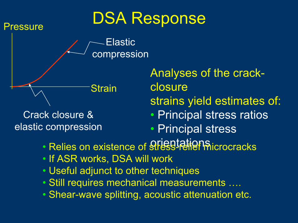
DSA Response
Strain
Crack closure &elastic compression
Elasticcompression
Analyses of the crack-closurestrains yield estimates of:• Principal stress ratios • Principal stress orientations• Relies on existence of stress-relief microcracks
• If ASR works, DSA will work• Useful adjunct to other techniques• Still requires mechanical measurements …. • Shear-wave splitting, acoustic attenuation etc.
Pressure

Round-Up• Experimental measurements are valuable
for all studies, i.e., wellbore to far-field, surface to TD
• Lab measurements provide data that can not otherwise be obtained (i.e., by logs)
• Coupled rock mechanics/petrophysicsstudies supplements + complements + enhances SCAL and log derived data
• Coupled geomechanics and dynamic reservoir simulation means such studies are increasingly needed and are becoming morecommon