Robustness Analysis of a mobile Phone - Dynardo · PDF fileMobile Phone Drop Test Simulation...
14
© 2010 Nokia All Rights Reserved Gerald Grewolls 22-Oct-2010 1 Robustness Evaluation of Mobile Phone Drop Test Simulation Gerald Grewolls Alexander Ptchelintsev This material, including documentation and any related computer programs, is protected by copyright controlled by Nokia. All rights are reserved. Copying, including reproducing, storing, adapting or translating, any or all of this material requires the prior written consent of Nokia. This material also contains confidential information, which may not be disclosed to others without the prior written consent of Nokia.
Transcript of Robustness Analysis of a mobile Phone - Dynardo · PDF fileMobile Phone Drop Test Simulation...
© 2010 Nokia All Rights Reserved Gerald Grewolls 22-Oct-20101
Robustness Evaluation of Mobile Phone Drop Test Simulation
Gerald Grewolls
Alexander Ptchelintsev
This material, including documentation and any related computer programs, is protected by copyright controlled by Nokia. All rights are reserved. Copying, including reproducing, storing, adapting or translating, any or all of this material requires the prior written consent of Nokia. This material also contains confidential information, which may not be disclosed to others without the prior written consent of Nokia.
Contents
• Mechanical Requirements for Mobile Phones
• Challenges in Drop Test Simulation
• Sensitivity & Robustness Study for Varying Drop Orientation
• Step 1: Sensitivity analysis
• Examples for Results
• Next Steps
• Summary
2 © 2010 Nokia All Rights Reserved Gerald Grewolls 22-Oct-2010
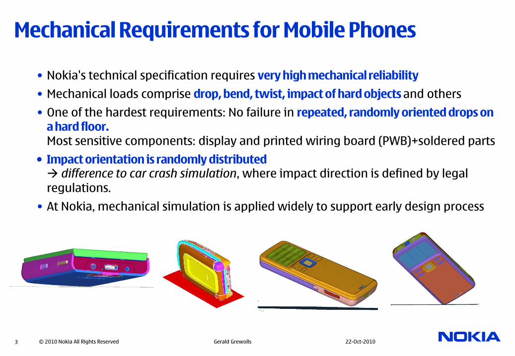
Mechanical Requirements for Mobile Phones
• Nokia's technical specification requires very high mechanical reliability
• Mechanical loads comprise drop, bend, twist, impact of hard objects and others
• One of the hardest requirements: No failure in repeated, randomly oriented drops on a hard floor.Most sensitive components: display and printed wiring board (PWB)+soldered parts
• Impact orientation is randomly distributed difference to car crash simulation, where impact direction is defined by legal
regulations.
• At Nokia, mechanical simulation is applied widely to support early design process
3 © 2010 Nokia All Rights Reserved Gerald Grewolls 22-Oct-2010

Challenges in Drop Test Simulation
• Stress results in components are very sensitive to the drop orientation
• Generally the drop on a corner with 2 or more subsequential impacts ("clattering") leads to maximum stresses
• For different drop orientations strongly non-linear variation of results due to different contact histories which are sensitive to small angle changes
• Geometric and material non-linearities to be considered additionally
4 © 2010 Nokia All Rights Reserved Gerald Grewolls 22-Oct-2010
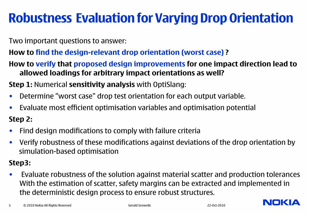
Robustness Evaluation for Varying Drop Orientation
Two important questions to answer:
How to find the design-relevant drop orientation (worst case) ?
How to verify that proposed design improvements for one impact direction lead to
allowed loadings for arbitrary impact orientations as well?
Step 1: Numerical sensitivity analysis with OptiSlang:
• Determine "worst case" drop test orientation for each output variable.
• Evaluate most efficient optimisation variables and optimisation potential
Step 2:
• Find design modifications to comply with failure criteria
• Verify robustness of these modifications against deviations of the drop orientation by
simulation-based optimisation
Step3:
• Evaluate robustness of the solution against material scatter and production tolerances
With the estimation of scatter, safety margins can be extracted and implemented in
the deterministic design process to ensure robust structures.
5 © 2010 Nokia All Rights Reserved Gerald Grewolls 22-Oct-2010
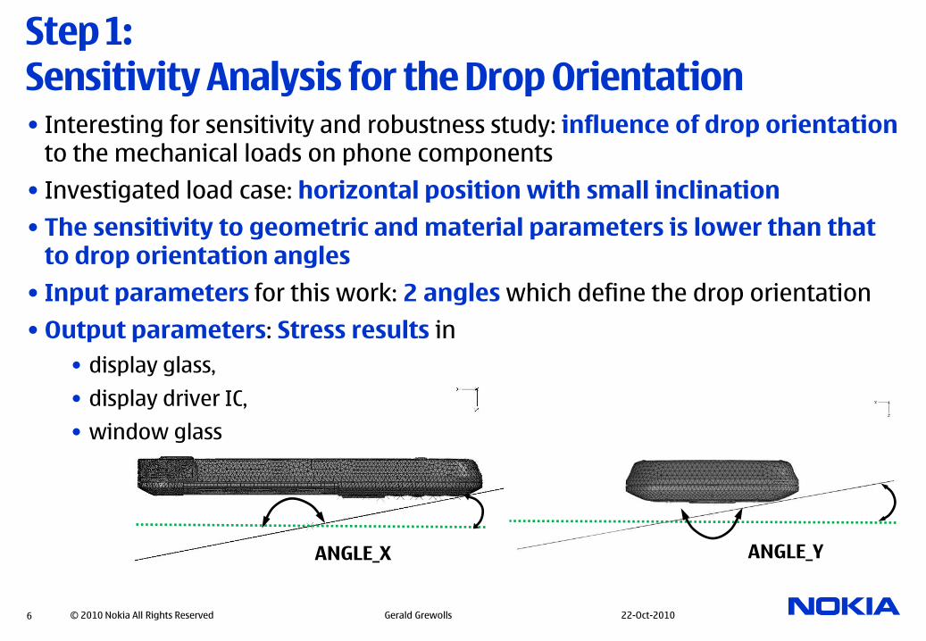
ANGLE_X
Step 1: Sensitivity Analysis for the Drop Orientation• Interesting for sensitivity and robustness study: influence of drop orientation
to the mechanical loads on phone components
• Investigated load case: horizontal position with small inclination
• The sensitivity to geometric and material parameters is lower than that to drop orientation angles
• Input parameters for this work: 2 angles which define the drop orientation
• Output parameters: Stress results in
• display glass,
• display driver IC,
• window glass
6 © 2010 Nokia All Rights Reserved Gerald Grewolls 22-Oct-2010
ANGLE_Y

Examples for Results
7 © 2010 Nokia All Rights Reserved Gerald Grewolls 22-Oct-2010
• Pictures in previous pages were examples for existing products.
• The following results are from a new product which was not yet published – no design pictures can be shown here.
• The results represent a very early development stage where many modifications are ongoing.

Example for Result: Stress at Glass Window Edge
8 © 2010 Nokia All Rights Reserved Gerald Grewolls 22-Oct-2010
Conclusion: Horizontal position (0°,0°) is less critical than impact on corners.
Investigate possible modifications to decrease stress peaks for ANGLE_X=-3°.

Example for Result: Stress in Display Driver IC
9 © 2010 Nokia All Rights Reserved Gerald Grewolls 22-Oct-2010
Conclusion: Extension of angle range is required to identify worst case orientation.

Example for Result: Stress in Display Glass
10 © 2010 Nokia All Rights Reserved Gerald Grewolls 22-Oct-2010
Conclusion: Extension of angle range is required to identify worst case orientation. Investigate possible modifications to decrease stress for orientations around (-4°,-4°).

© 2010 Nokia All Rights Reserved Gerald Grewolls 22-Oct-201011
Traffic Light Plot (new in OptiSlang 3.2.0)
Compare selected output parameters to safety limits (yellow) and failure limits (red).
Due to the random character of the drop orientation also the range [mean value + standard deviation] is a criterion to evaluate the risks to exceed failure limits in drop test.
Conclusions from step 1 (sensitivity analysis)
•The angle range should be increased to capture all critical drop orientations
•Some "worst-case-orientations" were found, these orientations for maximum stress results are hardly to predict on the basis of theory or engineering experience.
•Strongly non-linear character of results, Coefficients of Prognosis are relatively low due to steep result peaks which are randomly distributed. Result animations of the samples with the maximum stress deliver plausible pictures.
12 © 2010 Nokia All Rights Reserved Gerald Grewolls 22-Oct-2010

Next steps (Modification and Robustness Analysis)
•Implement structural modifications to decrease stress levels for worst-case orientations
•Evaluate robustness of the modifications by use of OptiSlang
13 © 2010 Nokia All Rights Reserved Gerald Grewolls 22-Oct-2010
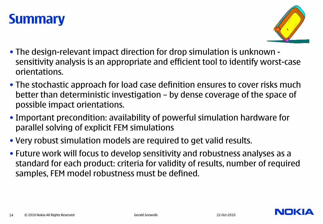
Summary
• The design-relevant impact direction for drop simulation is unknown -sensitivity analysis is an appropriate and efficient tool to identify worst-case orientations.
• The stochastic approach for load case definition ensures to cover risks much better than deterministic investigation – by dense coverage of the space of possible impact orientations.
• Important precondition: availability of powerful simulation hardware for parallel solving of explicit FEM simulations
• Very robust simulation models are required to get valid results.
• Future work will focus to develop sensitivity and robustness analyses as a standard for each product: criteria for validity of results, number of required samples, FEM model robustness must be defined.
14 © 2010 Nokia All Rights Reserved Gerald Grewolls 22-Oct-2010